Download - Circuit switching packet switching

P-88, MIDC Residential zone , Sagarli , Dombivli Gymkhana Road, Dombivli (East)
2013
CIRCUIT SWITCHING AND PACKET SWITCHING
CIRCUIT SWITCHING
NO CONTENTS PAGE
1 SWITCHED COMMUNICATION NETWORKS 4
2 CIRCUIT SWITCHING NETWORK 5
3 USE OF CIRCUIT-SWITCHING NETWORK 64 PUBLIC BRANCH EXCHANGE (PBX) 7
5 CIRCUIT ESTABLISHMENT 8
6 CIRCUIT-SWITCHING CONTENT 10
7 SPACE DIVISION SWITCHING 12
8 TIME DIVISION SWITCHING 13
9 PACKET SWITCHING 14
10 PACKET SWITCHING PRINCIPLE 15
11 SWITCHING TECHNIQUE 1912 PACKET SIZE 21
13 COMPARISON OF CIRCUIT SWITCHING AND PACKET SWITCHING
24
14 X.25 25
15 Frame Relay 28
16 Recommended reading 29

2
CIRCUIT SWITCHING & PACKET SWITCHING

3
What is switched communication Network.Switched communication Network. Introduction:
Communication is typically achieved by transmitting data from source to destination through a network of intermediate switching nodes. A switched network design is typically used to implement LAN’s as well. Switching nodes are not concerned with the content of the data; rather their purpose is to provide a switching facility that wills more the data from node to node until they reach their destination. The device attached to the network may be referred as stations. Stations may be computers, terminals, telephones or other communication devices. In a switched communication network, data entering the network from a station are routed to the destination by being switched from node to node. Nodes are connected to one another is some topology by transmission Link.
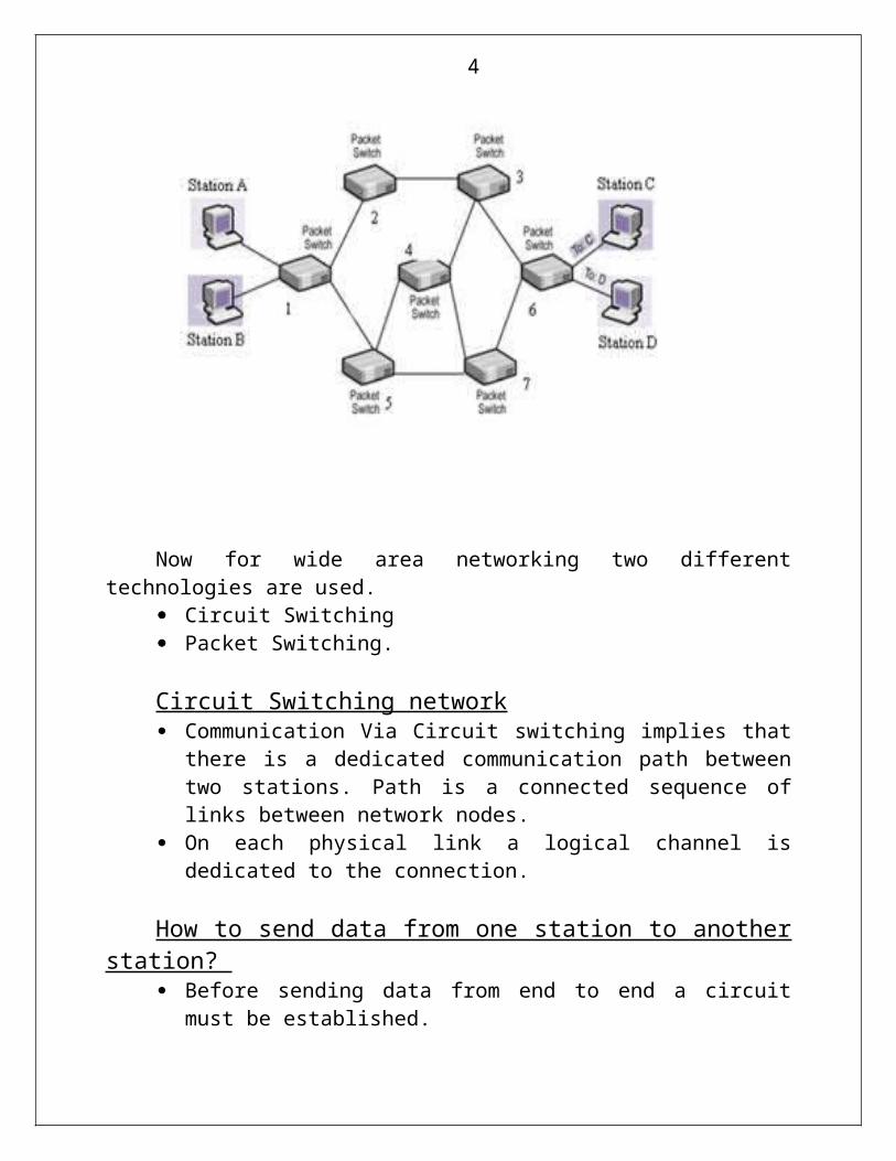
Now for wide area networking two different technologies are used. Circuit Switching Packet Switching.
4
Circuit Switching network Communication Via Circuit switching implies that there is a dedicated
communication path between two stations. Path is a connected sequence of links between network nodes.
On each physical link a logical channel is dedicated to the connection.
How to send data from one station to another station? Before sending data from end to end a circuit must be established. Station A sends a request to node 3 requesting a connection to station C
connection from node B to A is dedicated connection so part of the connection is already exists.
Now node 3 must find the next route leading to C, Based on Routing information and based on measures of availability and perhaps cost node 3 select the link to node 5 and then node 5 allocated the channel to node 6 then the node 6 completes the link with station C.
Data Transfer The transmission may be analog or digital, depending on the nature of
the network As the carriers en to fully integrated digital networks the use ;of digital
transmission for both (Dalvi, 2013) voice and data is becoming the dominant method.
Use of circuit- Switching Networks.

5
Circuit Switching was used to developed to handle voice traffic, but is now also used for data traffic.
Best Example of circuit switching is the public Telephone network. This is a collection of national networks interconnected to form ;the
international services The substantial data traffic is handle Via modem and the analog
telephone signal is converted into digital
Public Branch Exchange (PBX)

6
The well-known application of circuit switching is the private Branch Exchange (PNX) which is used to interconnect the telephone with in a building or office.
Circuit switching is also used in private networks such a network is set up by a corporation or the organization or large organization to interconnect its various sites.
Such system is interconnected by suing at each site interconnected by dedicated leased line obtain from one carriers such as JAT &T
Four generic Architectural component
Subscribers :- The devices that attach to the network. It is still the case that mast
subscriber devices to public telephone networks are telephones.
Subscriber lines The link between the subscriber and the network, it is also known as
subscriber loop or local loop. Almost all local loop connections use twisted- pair wire.
Exchanges:- The switching centers in the network. A switching center that directly supports subscribers is known as an end office. Intermediate switching nodes are used.
Exchanges The switching centers in the network , a switching center that
directly supports subscriber is known as an end office. Intermediate switching nodes are used.
Trunks. Trunks the branches between exchanges. Trunks carry multiple voice frequency circuit using either FDM or synchronous TDM
Circuit Establishment Subscribers connect directly to an end office, which switches traffic
between subscribers and between subscribers and other exchanges.

7
To connect two subscribers attached to the same and office, a circuit is set up between them
To connect two subscribers from different end offices, a circuit between them is consist of a chain of circuit through one or more intermediate office.
The connection between A and B by setting up the connection through the end office.
The connection between B1&B2 is more complex, the connection is established between line B1 and one channel on TDM trunk to intermediate switch
Circuit –Switching Concept.

8
A technology of circuit switching is between operations of a single circuit- switching node.
A network built around a single circuit-switching node consists of a collection of stations attached to a central switching unit.
The central switch establishes a dedicated path betwee3n any two devices that wish to communicate.
The function of the digital switch is to provide a transparent signal path between any pair of attached devices.
The path is transparent in that it appears to the attached pair of devices that there is a direct connection between them. Typically the connection must allow full - duplex transmission.
Task of Control Unit

9
The control performs three general tasks.
First :It establishes connection; this is generally done a demand, that is, at the request of an attached device. To establish the connection, the control unit must handle and acknowledge the request, determine if the intended destination is free, and construct a path through the switch.
Second : The control unit must maintain the connection.
Third : The control unit must tear down the connection, either in response to a request from one of the parties or for its own reasons.
Characteristic of a circuit switching device
Blocking or Non-Blocking Blocking – It is occur when the network is unable to connect two stations because all possible paths between them are already in use.
Non –Blocking network permits all stations to be connected at once and grants all possible connection requests as long as the called party is free.
Space Division Switching

10
1. Space Division Switching was originally developed for the analog or digital realm
2. Space Division switch is one in which the signal paths are physically separated from one another ( divided in space )
3. Each connection requires the establishment of a physical path through the switch that is dedicated solely to the transfer of signals between the two endpoints.
4. The basic building block of the switch is a metallic cross point or semi conductor gate that can be enabled and disabled by a control unit
The number of cross points grows with the square of the number of attached station. This is costly for a large switch.
The loss of a cross point prevents connection between the two devices whose lines intersect at that cross point.
Three- Stage Space Division Switch.The cross points are inefficiently utilized; even when all the attached
devices are active, only a small fraction of the cross points are engaged.

11
To overcome these limitations multiple-stage switches are employed.
This type of arrangement has two advantages over a single-stage crossbar matrix. The number of cross point is reduced, increasing crossbar utilization for
10 stations cross-point is reduced from 100 to 48. There is more than one path through the network to connect two
endpoints increasing reliability.
A multistate network requires a more complex control scheme. To establish a path in single-stage network, it is only necessary to enable a single gate. A single state cross-bar matrix is non-blocking, that is, a path is always
available to connect an input to an output. In Multistage is blocking one, even though output is available and the
second stage path is blocked the connection cannot be done.
We can able to make it non-blocking by increasing the number or size of the intermediate switches, but of course this increase the cost.
TIME DIVISION SWITCHING

12
With the advent of digitalize voice and synchronous time division multiplexing techniques both voice and data can be transmitted Via digital signals.
Instead of relatively dump space division systems, modern digital systems rely on intelligent control of space and time division elements.
Soft Switch Architecture.
i. The latest trend in the development of circuit switching technology is generally referred to as the soft switch.
A soft switch is a general purpose computer running specialized software that turns into smart phone switch
A soft switch can convert a stream of digitized voice bits into packets. This can opens up a number of options for transmission, including the
increasing popular voice over IP (Internet protocol) approach. In any telephone network switch, the most complex element is the
software that controls call processing. The software performs call routing and implements call-processing logic
for hundreds of custom calling features. Typically this software runs on a proprietary processor that is integrated
with public switching Hardware. A more flexible approach is to physically separate the call processing
function from the hardware switching function. In soft switch terminology, the physical switching function is performed
by a media gateway (N/G) and call processing logic resides in a media gate way controller (MGC).
PACKET SWITCHING

13
Packet Switching Principles
i. Circuit switching telecommunications networks was to handle voice traffic.
ii. The key characteristic of circuit switching is network is that resources within the network are dedicated to a particular call
iii. Circuit switching network began to be used increasingly for data connections.
iv. In a circuit-Switching network the connection provides for transmission at a constant data rate. Thus each of the two devices that are connected must transmit and receive at the same data rate as the other. This limits the utility of the networks in interconnecting a variety of host computers and work stations.
v. Packet switching address these problemsa. Data are transmitted in short packets. A typical upper bound on
packet length is 1000 octets. If the source has a longer message to send, the message is broken into a series of packets.
b. Each packet contains a portion of the user’s data plus some control information.
c. The control information at a minimum includes the minimum, includes the information that the network requires to be able to

14
route the packet through the network and deliver it to the intended destination.
At each node packet is received and stored it to the next node. Let us consider simple switching network. Consider a packet to be sent from A station to station C.
1) The packet includes control information that the intended destination is B.
2) The packet is sent from A to node 3 Node 3 stores the packet and determine the next route and queues the packet to go to that link B-4 link
3) When the link is available the packets sends the data from (4 to 5) and finally node 5 to destination B
4) The packets are queued up and transmitted as rapidly as possible over the link.
5) Packets switching network can perform data-rate conversion. Two different data rates can exchange packets because each connects to its node at its proper data rate.
When traffic becomes heavy on a circuit – switching network, some calls are blocked, i.e. the network refuses to accept additional connection request until the load on the network decrease. In jacket switching network, packets are still accepted, but delivery delay increases. Priority can be uses if a node has a number of packets queued for transmission it can transmit the higher priority packet first. These packets will therefore experiences less delay than lower priority packets.
Switching Technique

15
If a station has a message to send through a packet switching network that is of length greater than the maximum packet size, it breaks the message up into packet. These packets are sending one by one into packets. There are two networks are used in contemporary networks they are 1. Datagram 2. Virtual circuit.
Datagram.1. In the Datagram approach each packets is treated independently, with
no reference to packets that have gone before.2. This approach shows a time sequence of snapshots of the progress of
three packets through the network. 3. Each node choose the next node and pockets path taking into account
information received from neighboring nodes on traffic, line failure and soon.
4. So the packet with same destination address do not all follow the same route, and they may drive out of sequence at the exits point
5. In this example, the exits node restores the packet to their original order before delivering them to the destination.
6. In some datagram network it is up to the destination rather than the exit node to do the recording.
7. It is possible for a packet to be destroyed in the network for e.g. if a packet- switching node crashes momentarily all its queued packets may be lost.
8. It is up to either the exit node or the destination to detect the loss of a packet and decide now to recover it.
9. In datagram technique, each packet, treated independently.

16
Figure 1 Packet Switching: Datagram approach

17
Virtual Circuit. 1. In the virtual circuit approach, a preplanned route is established before
any packets are sent. 2. Once the route is established all the packets between a pair of
communicating parties follow the same route through the network. 3. The route is fixed for the duration of the logical connection it is
somewhat similar to a circuit in a circuit switching network and it is referred to a virtual circuit.
4. Each node on the pre established route knows where to direct such packets no routing decisions are required.
5. Each station can have more than one virtual circuit to any other station and can have virtual circuits to more than one station.

18
Main characteristic of the virtual circuit technique is that the route between stations is set up prior to data transfer.
(Note:- It does not mean that this is a dedicated path, as in circuit Switching)
I. A transmitted packet is buffered at circuits may share the use of the line.
II. The difference from the datagram approach is that with virtual circuits, the node need not make a routing decision for each packet. It is made only once for all packets using that virtual circuit.
III. If two stations wish to exchange data over on extended period of time there are certain advantages to virtual circuits. a. First the network may provide services related to the virtual circuit
including sequencing and error control. b. Sequencing means all packets follow she same route, they arrive
in the original order. c. Node 6 can request a retransmission of that packet from node 4 d. Another advantage is that packets should transmit the network
more rapidly with a virtual circuit, it is not necessary to make a routing decision for each packet at each node.
Advantages of Datagram Approach.
i. The call setup phase is avoided If a station wishes to send only one or a few packets datagram delivery will be quicker.
ii. It is more primitive more flexible.

19
Packet Size There is a significant relationship between packet sized and transmission time. 1. There is a virtual circuit from station X through nodes A and and B to
station Y 2. If the entire message is sent as single packet of 43 octets ( 3 octets of
data )then the packet is first transmitted from station X to node a.3. When the entire packet is received at node B, it is then transferred to
station Y. Ignoring switching time, total transmission time is 129 octet-time ( 43 octets × 3 packet transmissions)
Figure 2 Effect of packet size on transmission line
4. Break the message up into two packets, each containing 20 octets of the message and, of course, 3 octets each of header, or control information.

20
5. In this case, node a can begin transmitting the first packet as soon as it has arrived from X, without waiting for second packet. Because of this overlap in transmission, the total transmission time drops to 92 octet-times.
6. By breaking the message up into five packets, each intermediate node can begin transmission even sooner and the savings in time is greater with a total of 77 octet-times for transmission.
7. This process of using more and smaller packet eventually result in increased ,rather than reduced delay ,because each packet contains a fixed amount of header ,and more packets mean more of these headers.
8. The delay are also greater when more packets are handled for a single message .

21
Comparison of Circuit Switching and Packet SwitchingHaving looked at the internal operation of packet switching, we can return to a comparison of this technique with circuit switching.Important issue of performance PerformanceThe transmission of the message across four nodes, from a source station attached to node 1 to the destination attached to the node 4.we are concerned with three types of delay
Propagation delay: The time it takes a signal to propagate from one node to the next .This time is generally negligible, the speed of electromagnetic signals through a wire medium, for example 2×10^8 m/s.
Transmission time: The time it takes for transmitter to send out a block of data .For example, it takes 1s to transmit a 10,000-bit block of data onto a 10-kbps line.
Node delay: The time it takes for a node to perform the necessary processing as it switches data.
Figure 3 Event timing for circuit switching and packet switching

22
In circuit switching, there is a certain amount of delay before the message can be sent.
First ,a call Request signal is sent through the network, to set up a connection to the destination. If the destination station is not busy, a Call Accepted signal returns.
A processing delay is incurred at each node during the call request; this time is spent on each node setting up the route of the connection.
On the return, this processing is not needed because the connection is sent as a single block ,with no notice-able delay at the switching nodes.
Virtual circuit packet switching A virtual circuit is requested using a call request packet, which incurs
a delay at each node. A virtual circuit is accepted with a Call Accept packet. In contrast to
the circuit-switching case, the call acceptance also experiences node delay, even through the virtual circuit route is now established.
This is because the packet is queued at each node and must wait its turn for transmission. Once the circuit is established the message is transmitted in packets.
Packet switching involves some delay at each node in path.worse, this delay is variable and will increase with increased load.
Data packet switching A data packet switching does not require a call setup, for short
message it will be faster than virtual circuit packet switching and perhaps circuit switching.
Each individual datagram is routed independently, the processing for each datagram at each node may be longer than the virtual circuit packets
Virtual circuit switching technique is superior for long messages. Figure 3 is intended only to suggest what the relative techniques Actual performance depends on a host of factors; including the size
of network ,its topology, the pattern of load, and the characteristics of typical exchanges

23
Comparision of Communication Switching Network
Circuit Switching Datagram Packet Switching
Virtual circuit Packet switching
Dedicate transmission path
No dedicate path No dedicate path
Continuous transmission of data
Transmission of packets Transmission of packets
Fast enough for interactive
Fast enough for interactive
Fast enough for interactive
Message are not stored Packets may be stored until delivered
Packets stored until delivered
The path is established for entire conversation
Route established for each packet
Route established for entire conversation
Call setup delay; negligible transmission delay
Packet transmission delay Call setup delay; Packet transmission delay
Busy signal if called party busy
Sender may be notified if packet not delivered
Sender notified of connection denial
Overload may block call setup; no delay for established calls
Overload increases packet delay
Overload may block call setup; increases packet delay
Electromechanical or computerized switching nodes
Small switching nodes Small switching nodes
User responsible for message loss protection
Network may be responsible for individual packets
Network may be responsible for packet sequences
Usually no speed or code conversion
Speed and code conversion
Speed and code conversion
Fixed bandwidth Dynamic use of bandwidth
Dynamic use of bandwidth
No overhead bits after call setup
Overhead bits in each packet
Overhead bits in each packet
Figure 4 Comparison of Communication switching technique

24
X.25One technical aspect of packet-switching networks remains to be examined:
The interface between attached devices and the network. We have seen that a circuit switching network provides a transparent communication path for attached device that makes it appear that the two communication station have direct link.
In packet switching network, the attached station must organize their data into packets for transmission. This requires a certain level of cooperation between the network and the attached stations. The standard used for traditional packet –switching network is X.25.
X.25 is an ITU-T standard that specifies an interface between a host system and a packet –switching network. The functionality of X.25 is specified on three levels:
Physical level Link level Packet level

25
The use of virtual circuitsThe physical level deals with the physical interface between an attached
station (computer, terminal) and the link that attaches that station to the packet-switching node. It makes the use of the physical-level specification in a standard known as X.21
The link level provides for the reliable transfer of data across the physical link, by transmitting the data as a sequence of frames. The link level standard is referred to as LAPB (Link Access Protocol-Balanced).
The packet level provides a virtual circuit service; this service enables any subscriber to the network to set up logical connections, called virtual circuit to other subscribers.
The term virtual circuit refers to the logical connection between two stations through the network. Earlier the term virtual circuit to refer to a special preplanned route through the network between two stations; this could be called an internal virtual circuit. There is one-one relationship between external and internal virtual circuit, there is a logical relationship, or logical channel, established between two stations and all of the data associated with the logical channel are considered as single stream of data between the two stations.
Figure 5 User Data and X.25 Protocol Control Information
The relationship among the level of X.25 includes send and receives sequence numbers. The send sequence number is used to number sequentially all outgoing data packets on a particular virtual circuit. The receive sequence number is an acknowledgement of packets received on that virtual circuit

26
Frame Relay Frame relay is designed to provide a more efficient transmission scheme
than X.25.the standards for frame relay matured earlier than those for ATM,and commercial products also arrived earlier .Accordingly, there is a large installed base of frame relay products. Interest has since shifted to ATM for high-speed data networking.
BackgroundThe traditional approach to packet switching makes use of X.25, which not only determines the user-network interface but also influences the internal design of the network
Call control packets, used for setting up and clearing virtual circuits, are carried on the same channels and same virtual circuit as data packets
Multiplexing of virtual circuits take place at layer 3. Both layer 2 and layer 3 include flow control and error control
mechanisms.The X.25 approach results in considerable overhead. At each hop through the network, the data link control protocol involves the exchange of a data frame and a acknowledgement frame. Furthermore, at each intermediate node, state tables must be maintained for each virtual circuit to deal with the call management and flow control/error control aspects of the X.25 protocol. All the overhead may be justified when there is a significant probability of error on any of the link on the internet Frame relay is designed to eliminate much of the overhead that X.25 imposes on end user system and on the packet-switching network.The key differences between frame relay and the conventional X.25 packet switching services are as follows
Call control signaling, which is information needed to set up and manage a connection, is carried on a separate logical connection from user data. Thus intermediate nodes need not maintain state table or process messages relating to call control on an individual per-connection basis
There is a hop-by-hop flow control and error control. End to end flow control and error control are the responsibility of a higher layer, if they are employed at all.

27
Frame relay protocol Architecture
Figure 6 : Frame Relay User-network Interface protocol Architecture
The fig 6 depicts the protocol architecture to support the frame mode bearer service.we need to consider two separate planes of operation: a control © plane, which is involved in the establishment and termination of logical connections, and a user (u) plane, which is responsible for the transfer of user data between subscribers. Thus, c-plane protocols are between a subscriber and a network, while U-plane protocols are between a subscriber and the network, while U-plane protocols provide end to end functionality.
Control plane The control plane for frame mode bearer services is similar to that for common channel signaling for circuit-switching services, in that a separate logical channel is used for control information. At the data link layer is usedto reliable data link control
User plan e For the actual transfer of information between end users, the user-plane protocol is LAPF (Link Access Procedure for Frame Mode Bearer Services),
Only the core function are used for frame relay .

28
Recommended Reading Data and Computer CommunicationsEighth edition
-By Willian Stallings


