TOC
Design Manual
Chapter 12 - Sidewalks and Bicycle Facilities
Table of Contents
i Revised: 2013 Edition
Table of Contents
Chapter 12 - Sidewalks and Bicycle Facilities
12A Sidewalks
12A-1---------------------------------General Sidewalk Requirements
A. Introduction............................................................................................................. 1
B. Sidewalk Classes.................................................................................................... 1
C. Accessible Sidewalk Design................................................................................... 2
D. Construction Requirements.................................................................................... 2
12A-2---------------------------------Accessible Sidewalk Requirements
A. Introduction............................................................................................................. 1
B. Transition Plan........................................................................................................ 2
C. Definitions.............................................................................................................. 2
D. Applicability........................................................................................................... 3
E. Standards for Accessibility..................................................................................... 6
F. Bus Stop................................................................................................................ 15
G. Accessible Pedestrian Signals.............................................................................. 15
12A-3---------------------------------Protruding Objects
A. Introduction............................................................................................................. 1
B. Protruding Object Locations................................................................................... 1
C. Clearance................................................................................................................ 2
12A-4---------------------------------Pedestrian Facilities During Construction
A. Introduction............................................................................................................. 1
B. Evaluating Pedestrian Needs.................................................................................. 1
C. Facility Options...................................................................................................... 1
D. Barricades, Channelizing Devices, and Signs........................................................ 2
E. Temporary Pedestrian Facilities............................................................................. 2
F. Utility Construction................................................................................................ 2
12B Bicycle Facilities
12B-1---------------------------------Bicycle and Pedestrian Facilities
A. Introduction............................................................................................................. 1
B. Definitions.............................................................................................................. 1
C. Design Process........................................................................................................ 2
12B-2---------------------------------Shared Use Path Design
A. Accessible Shared Use Path Design....................................................................... 1
B. Shared Use Path Categories.................................................................................... 1
C. Shared Use Path Design Elements.......................................................................... 2
D. Intersection Sight Distance..................................................................................... 9
Chapter 12 - Sidewalks and Bicycle Facilities Table of Contents
ii Revised: 2013 Edition
E. Surface.................................................................................................................. 11
F. Crossings at Unpaved Surfaces............................................................................ 11
G. At-grade Railroad Crossing.................................................................................. 12
H. Drainage............................................................................................................... 12
I. Structure Design................................................................................................... 13
J. Pavement Markings.............................................................................................. 13
K. Signing.................................................................................................................. 14
L. Lighting ............................................................................................................... 14
12B-3---------------------------------On-Street Bicycle Facilities
A. General.................................................................................................................... 1
B. Elements of Design................................................................................................. 1
C. Facilities.................................................................................................................. 1
D. Bicycle Guide Signs............................................................................................... 7
E. Railroad Crossings for Bicycles............................................................................. 7
F. Obstruction Markings for Bicycle Lanes................................................................ 7
G. Traffic Signals for Bicycles.................................................................................... 7
H. Bridges and Viaducts for Bicycles......................................................................... 8
I. Traffic Calming and Management of Bicycles....................................................... 8
J. Intake Grates and Manhole Castings for Bicycle Travel........................................ 8
K. Bicycles at Interchanges......................................................................................... 8
L. Bicycles at Roundabouts......................................................................................... 9
12A-1
Design Manual
Chapter 12 - Sidewalks and Bicycle Facilities
12A - Sidewalks
1 Revised: 9/20/2012
SUDAS 2013 Edition
General Sidewalk Requirements
A. Introduction
Sidewalks are an integral component of the transportation system. They provide a designated area,
separated from the roadway, for pedestrians to use for both travel and recreation. Along roadways
where pedestrians are present or anticipated, consideration should be given to constructing sidewalks
on both sides of the road to minimize conflicts between vehicles and pedestrians.
Where sidewalks are provided, they must be constructed so they are accessible to all potential users,
including those with disabilities. Design standards for pedestrian access routes are provided in
Section 12A-2.
B. Sidewalk Classes
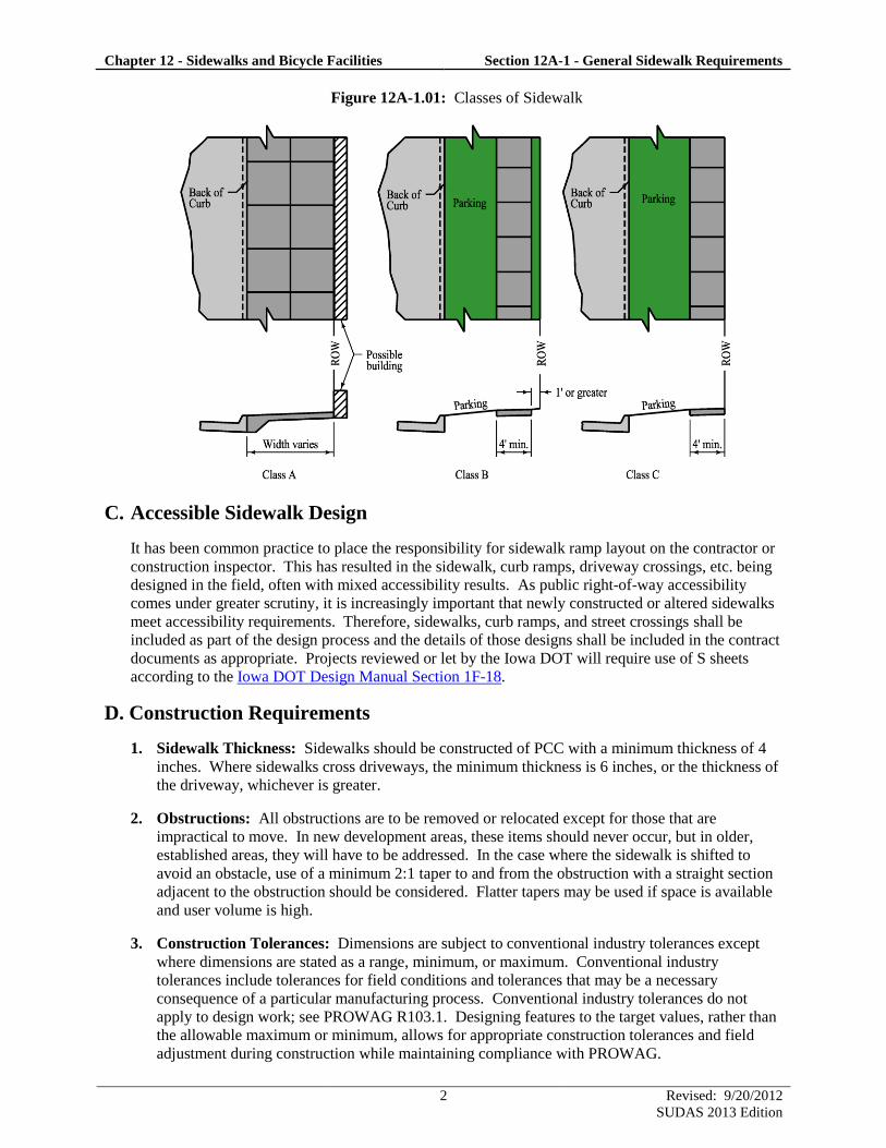
SUDAS identifies three classes of sidewalks, which are described below. Class B and C sidewalks
provide a grass strip between the back of curb and the sidewalk, often referred to as the “parking.”
1. Class A: Class A sidewalks begin at the back of curb and generally extend to the right-of-way
line. These types of sidewalks are typical in downtown areas. Consideration must be given to the
location of street signs, street lighting, utilities, mailboxes, snow storage, and other obstacles
when utilizing Class A sidewalk.
2. Class B: Class B sidewalks are constructed with the back edge of the sidewalk 1 foot or more off
of the right-of-way line.
3. Class C: Class C sidewalks have the back edge of the sidewalk on the right-of-way line.
Chapter 12 - Sidewalks and Bicycle Facilities Section 12A-1 - General Sidewalk Requirements
2 Revised: 9/20/2012
SUDAS 2013 Edition
Figure 12A-1.01: Classes of Sidewalk
C. Accessible Sidewalk Design
It has been common practice to place the responsibility for sidewalk ramp layout on the contractor or
construction inspector. This has resulted in the sidewalk, curb ramps, driveway crossings, etc. being
designed in the field, often with mixed accessibility results. As public right-of-way accessibility
comes under greater scrutiny, it is increasingly important that newly constructed or altered sidewalks
meet accessibility requirements. Therefore, sidewalks, curb ramps, and street crossings shall be
included as part of the design process and the details of those designs shall be included in the contract
documents as appropriate. Projects reviewed or let by the Iowa DOT will require use of S sheets
according to the Iowa DOT Design Manual Section 1F-18.
D. Construction Requirements
1. Sidewalk Thickness: Sidewalks should be constructed of PCC with a minimum thickness of 4
inches. Where sidewalks cross driveways, the minimum thickness is 6 inches, or the thickness of
the driveway, whichever is greater.
2. Obstructions: All obstructions are to be removed or relocated except for those that are
impractical to move. In new development areas, these items should never occur, but in older,
established areas, they will have to be addressed. In the case where the sidewalk is shifted to
avoid an obstacle, use of a minimum 2:1 taper to and from the obstruction with a straight section
adjacent to the obstruction should be considered. Flatter tapers may be used if space is available
and user volume is high.
3. Construction Tolerances: Dimensions are subject to conventional industry tolerances except
where dimensions are stated as a range, minimum, or maximum. Conventional industry
tolerances include tolerances for field conditions and tolerances that may be a necessary
consequence of a particular manufacturing process. Conventional industry tolerances do not
apply to design work; see PROWAG R103.1. Designing features to the target values, rather than
the allowable maximum or minimum, allows for appropriate construction tolerances and field
adjustment during construction while maintaining compliance with PROWAG.
12A-2
Design Manual
Chapter 12 - Sidewalks and Bicycle Facilities
12A - Sidewalks
1 Revised: 8/16/2013
SUDAS 2014 Edition
Accessible Sidewalk Requirements
A. Introduction
SUDAS and Iowa DOT jointly developed this section based on the July 26, 2011 “Proposed
Accessibility Guidelines for Pedestrian Facilities in the Public Right-of-Way.” This section was
developed in accordance with Federal regulations (23 CFR 652 and 28 CFR 35) and is the standard
for use by all governmental entities in the State of Iowa. A local jurisdiction may elect to produce
their own standards; however, these will require review and approval by FHWA and/or the United
States Department of Justice.
Where sidewalks are provided, they must be constructed so they are accessible to all potential users,
including those with disabilities. This section establishes the criteria necessary to make an element
physically accessible to people with disabilities. This section also identifies what features need to be
accessible and then provides the specific measurements, dimensions, and other technical information
needed to make the feature accessible. The requirements of this section were developed based on the
following documents:
1. ADAAG: The “Americans with Disabilities Act Accessibilities Guidelines” (ADAAG) was
written by the US Access Board and adopted by the Department of Justice (DOJ) in 2010. This
document includes a broad range of accessibility guidelines including businesses, restaurants,
public facilities, public transportation, and sidewalks. These standards were originally adopted in
1991 and have been expanded and revised several times.
2. PROWAG: The July 26, 2011 “Proposed Accessibility Guidelines for Pedestrian Facilities in
the Public Right-of-Way” was written by the US Access Board and is also known as the Public
Right-of-Way Accessibility Guidelines or PROWAG. PROWAG provides more specific
information than the ADAAG for transportation facilities within the right-of-way including
pedestrian access routes, signals, and parking facilities. The PROWAG requirements are
currently in the development and adoption process and have not been officially adopted by the
Department of Justice; however, the Federal Highway Administration has issued guidance that
the draft version of the PROWAG “are currently recommended best practices, and can be
considered the state of the practice that could be followed for areas not fully addressed” in the
existing ADAAG requirements.
Due to the widespread acceptance of the PROWAG, and their pending adoption in the future, the
standards of this chapter are based upon the PROWAG requirements. The designer is encouraged
to reference the complete PROWAG document for additional information (www.access-
board.gov). References to the PROWAG in this section are shown in parentheses, e.g. (R302.7).
Buildings and other structures not covered by PROWAG must comply with the applicable
requirements of the ADAAG. For parks, recreational areas, and shared use paths, refer to other
sections within this chapter.
Chapter 12 - Sidewalks and Bicycle Facilities Section 12A-2 - Accessible Sidewalk Requirements
2 Revised: 8/16/2013
SUDAS 2014 Edition
B. Transition Plan
The ADA law passed in 1990 required public entities with more than 50 total employees to develop a
formal transition plan identifying the steps necessary to meet ADA accessibility requirements for all
pedestrian access routes within their jurisdiction by upgrading all noncompliant features.
Recognizing that it would be difficult to upgrade all facilities immediately, the law provided the
opportunity to develop a transition plan for the implementation of these improvements. Covered
entities had until 1992 to complete a transition plan. In addition, any local public agency that is a
recipient of US DOT funds must have a transition plan. For those agencies that have not completed a
transition plan, it is critical that this process be completed. Although the transition plan may cover a
broader scope, this section will only cover requirements within the public right-of-way.
Key elements of a transition plan include the following:
Identifying physical obstacles in the public agency’s facilities that limit the accessibility of its
programs or activities to individuals with disabilities
A detailed description of the methods that will be used to make the facilities accessible
A schedule for taking the steps necessary to upgrade pedestrian access in each year following the
transition plan
Identification of the individual responsible for implementation of the plan
The document: ADA Transition Plans: A Guide to Best Management Practices (NCHRP Project No.
20-7 (232)) provides guidance for the development and update of transition plans. The document also
assists communities in prioritizing required improvements for accessibility.
Public entities not required to have a formal transition plan are required to address noncompliant
pedestrian access routes.
C. Definitions
Accessible: Facilities that comply with the requirements of this section.
Alteration: An alteration is a change that affects or could affect the usability of all or part of a
building or facility. Alterations of streets, roadways, or highways include activities such as
reconstruction, rehabilitation, resurfacing, widening, and projects of similar scale and effect.
Alternate Pedestrian Access Route: A route provided when a pedestrian circulation path is
temporarily closed by construction, alterations, maintenance operations, or other conditions.
Curb Line: A line at the face of the curb that marks the transition between the curb and the gutter,
street, or highway.
Cross Slope: The grade that is perpendicular to the direction of pedestrian travel.
Crosswalk: See pedestrian street crossing.
Curb Ramp: A ramp that cuts through or is built up to the curb. Curb ramps can be perpendicular,
parallel, or a combination of parallel and perpendicular curb ramps.
Detectable Warning: Detectable warnings consist of small, truncated domes built in or applied to a
walking surface that are detectable by cane or underfoot. On pedestrian access routes, detectable
warning surfaces indicate the boundary between a pedestrian route and a vehicular route for
pedestrians who are blind or have low vision.
Chapter 12 - Sidewalks and Bicycle Facilities Section 12A-2 - Accessible Sidewalk Requirements
3 Revised: 8/16/2013
SUDAS 2014 Edition
New Construction: Construction of a roadway where an existing roadway does not currently exist.
Pedestrian Access Route: A continuous and unobstructed path of travel provided for pedestrians
with disabilities within, or coinciding with, a pedestrian circulation path.
Pedestrian Circulation Path: A prepared exterior or interior surface provided for pedestrian travel
in the public right-of-way.
Pedestrian Street Crossing: A marked or unmarked route, providing an accessible path to travel
from one side of the street to the other. Pedestrian street crossings are a component of the pedestrian
access route and/or the pedestrian circulation path.
Running Slope: The grade that is parallel to the direction of pedestrian travel.
PROWAG: The Public Right-of-way Accessibility Guidelines establish the criteria for providing a
feature within the public right-of-way that is physically accessible to those with physical disabilities.
Scope of the Project: Work that can reasonably be completed within the limits of the project. This
is not defined by the written project scope; however, it focuses on whether the alteration project
presents an opportunity to design the altered element, space, or facility in an accessible manner.
Structurally Impracticable: Something that has little likelihood of being accomplished because of
those rare circumstances when the unique characteristics of terrain prevent the incorporation of full
and strict compliance with this section. Applies to new construction only.
Technically Infeasible: With respect to an alteration of an existing facility, something that has little
likelihood of being accomplished because existing structural conditions would require removing or
altering a load-bearing member that is an essential part of the structural frame; or because other
existing physical or site constraints prohibit modification or addition of elements, spaces, or features
that are in full and strict compliance with the requirements of this section. (2010 ADAAG 106.5)
Turning Space: An area at the top or bottom of a curb ramp, providing a space for pedestrians to
stop, rest, or change direction.
D. Applicability
1. New Construction: Newly constructed facilities within the scope of the project shall be made
accessible to persons with disabilities, except when a public agency can demonstrate it is
structurally impracticable to provide full compliance with the requirements of this section.
Structural impracticability is limited to only those rare situations when the unique characteristics
of terrain make it physically impossible to construct facilities that are fully compliant. If full
compliance with this section is structurally impracticable, compliance is required to the extent
that it is not structurally impracticable. [2010 ADAAG 28 CFR 35.151(a)]
2. Alterations: Whenever alterations are made to the pedestrian circulation path, the pedestrian
access route shall be made accessible to the maximum extent feasible within the scope of the
project. If full compliance with this section is technically infeasible, compliance is required to
the extent that it is not technically infeasible. [2010 ADAAG 28 CFR 35.151(b)] Alterations
shall not gap pedestrian circulation paths in order to avoid ADA compliance.
Chapter 12 - Sidewalks and Bicycle Facilities Section 12A-2 - Accessible Sidewalk Requirements
4 Revised: 8/16/2013
SUDAS 2014 Edition
Resurfacing is an alteration that triggers the requirement for curb ramps if it involves work on a
street or roadway spanning from one intersection to another. Examples include, but are not
limited to, the following treatments or their equivalents:
New layer of surface material (asphalt or concrete, including mill and fill)
Reconstruction
Concrete pavement rehabilitation and reconstruction
Open-graded surface course
Microsurfacing and thin lift overlays
Cape seals (slurry seal or microsurfacing over a new chip seal)
In-place asphalt recycling
[DOJ/U.S. DOT Glossary of Terms and DOJ/U.S. DOT Technical Assistance; June 28, 2013]
Where elements are altered or added to existing facilities, but the pedestrian circulation path is
not altered, the pedestrian circulation path is not required to be modified (R202.1). However,
features that are added shall be made accessible to maximum extent feasible. The following are
examples of added features:
Installation of a traffic sign does not require sidewalk improvements; however, the sign
cannot violate the protruding objects requirements.
Installation of a traffic or pedestrian signal does not require sidewalk improvements;
however, the signal must be accessible.
Installation of a bench adjacent to the pedestrian access route would not require sidewalk
improvements, but the bench cannot be placed in a manner that would reduce the sidewalk
width below the minimum requirement.
3. Maintenance: Accessibility improvements are not required for work that is considered
maintenance. Examples of work that would be considered maintenance include, but are not
limited to, the following items.
Painting pavement markings, excluding parking stall delineations
Crack filling and sealing
Surface sealing
Chip seals
Slurry seals
Fog seals
Scrub sealing
Joint crack seals
Joint repairs
Dowel bar retrofit
Spot high-friction treatments
Diamond grinding
Minor street patching (less than 50% of the pedestrian street crossing area)
Curb and gutter repair or patching outside the pedestrian street crossing
Minor sidewalk repair that does not include the turning space and curb ramps
Filling potholes
If a project involves work not included in the list above, or is a combination of several
maintenance items occurring at or near the same time, the agency administering the project is
responsible for determining if the project should be considered maintenance or an alteration. If
either of these two situations is determined to be maintenance, the agency administering the
project must document the reasons for this determination. If the project is defined as
maintenance, federal funding and Farm-to-Market funds cannot be used.
Chapter 12 - Sidewalks and Bicycle Facilities Section 12A-2 - Accessible Sidewalk Requirements
5 Revised: 8/16/2013
SUDAS 2014 Edition
When a maintenance project modifies a crosswalk, installation of curb ramps at the crosswalks is
recommended, if none already exists. The other accessibility improvements of this section are
also recommended, but not required with such projects.
4. Technical Infeasibility: Examples of existing physical or site constraints that may make it
technically infeasible to make an altered facility fully compliant include, but are not limited to,
the following:
Right-of-way availability. Right-of-way acquisition in order to achieve full compliance is not
mandatory, however, it should be considered. Improvements may be limited to the maximum
extent practicable within the existing right-of-way.
Underground structures that cannot be moved without significantly expanding the project
scope.
Adjacent developed facilities, including buildings that would have to be removed or relocated
to achieve accessibility.
Drainage cannot be maintained if the feature is made accessible.
Notable natural or historic features that would have to be altered in a way that lessens their
aesthetic or historic value.
Underlying terrain that would require a significant expansion of the project scope to achieve
accessibility.
Street grades within the crosswalk exceed the pedestrian access route maximum cross slopes,
provided an engineering analysis has concluded that it cannot be done without significantly
expanding the project scope (for example, changing from resurfacing an intersection to
reconstructing that intersection).
5. Safety Issues: When accessibility requirements would cause safety issues, compliance is
required to the maximum extent practicable.
6. Documenting Exceptions: If the project cannot fully meet accessibility requirements because
the accessibility improvements are structurally impracticable, technically infeasible, or safety
issues, a document should be developed to describe how the existing physical or site constraints
or safety issues limit the extent to which the facilities can be made compliant. This document
should identify the specific locations that cannot be made fully compliant and provide specific
reasons why full compliance cannot be achieved. It is recommended that this document be
retained in the project file. For local agency projects administered through Iowa DOT, an
“Accessibility Exceptions Certification” (Form 517118) with supporting documentation shall be
signed by a registered professional engineer or landscape architect licensed in the State of Iowa
and submitted to the Iowa DOT administering office. The certification shall be as prescribed by
Iowa DOT Local Systems I.M. 1.080. For Iowa DOT projects, contact the Office of Design,
Methods Section.
Note: Documenting exceptions does not remove an agency’s responsibility to consider making
accessibility improvements the next time the facility is altered because physical or site constraints
and safety issues may change over time. The determination of exceptions and corresponding
documentation needs to be made each time a facility is altered, based on the existing conditions
and the scope of the proposed project.
7. Reduction in Access: Regardless of whether the additions or alterations involve the
modification of the existing pedestrian circulation path, the resulting work cannot have the result
of reducing the existing level of accessibility below the minimum requirements. For example, the
installation of a bench cannot have the effect of reducing the width of the pedestrian access route
to 3 feet (4 feet is the minimum). Likewise, the construction of an overlay cannot result in a
street cross slope of more than 5%, nor have a lip at the curb ramp that exceeds 1/2 inch.
Chapter 12 - Sidewalks and Bicycle Facilities Section 12A-2 - Accessible Sidewalk Requirements
6 Revised: 8/16/2013
SUDAS 2014 Edition
Pedestrian facilities may be removed if they are being re-routed for safety reasons, or terminated
because they do not connect to a destination or another pedestrian circulation path.
8. Addition of Pedestrian Facilities: If a sidewalk exists on both sides of the street, curb ramps
shall be installed on both sides when the street is altered. PROWAG does not require
construction of pedestrian facilities where none currently exists, although the jurisdiction’s
transition plan may require them.
9. Utility Construction: If the pedestrian circulation path is disturbed during utility construction,
the requirements of this section and Section 12A-4 shall apply.
E. Standards for Accessibility
The following section summarizes the design standards for the elements of an accessible pedestrian
access route. The minimum and maximum values stated are taken from the PROWAG. Target
values are also provided. Designing features to the target values, rather than the allowable maximum
or minimum, allows for appropriate construction tolerances and field adjustment during construction
while maintaining compliance with the PROWAG standards.
1. General Requirements: These requirements apply to all parts of the pedestrian access route.
a. Surfacing: PROWAG requires all surfaces to be firm, stable, and slip resistant (R302.7).
All permanent pedestrian access routes, with the exception of some Type 2 shared use paths
(see Section 12B-2), shall be paved. When crossing granular surfaced facilities, consider
paving wider than the pedestrian access route; see the shared use path section.
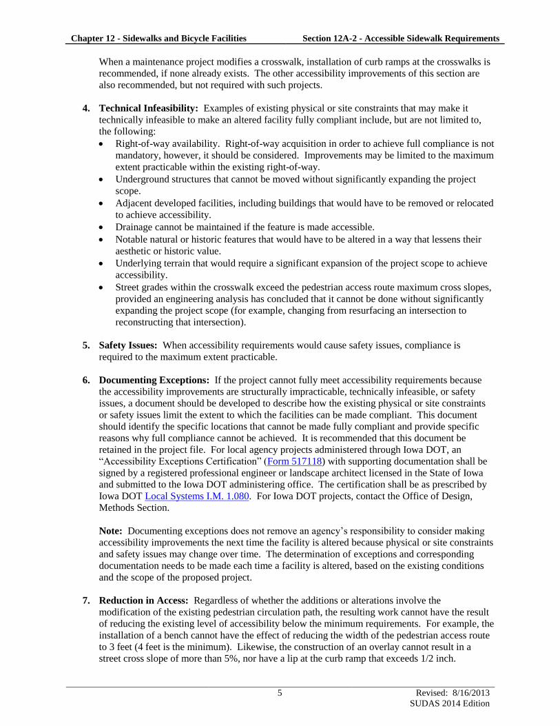
b. Changes in Level: Changes in level, including bumps, utility castings, expansion joints, etc.
shall be a maximum of 1/4 inch without a bevel or up to 1/2 inch with a 2:1 bevel. Where a
bevel is provided, the entire vertical surface of the discontinuity shall be beveled (R302.7.2).
Figure 12A-2.01: Vertical Surface Discontinuities
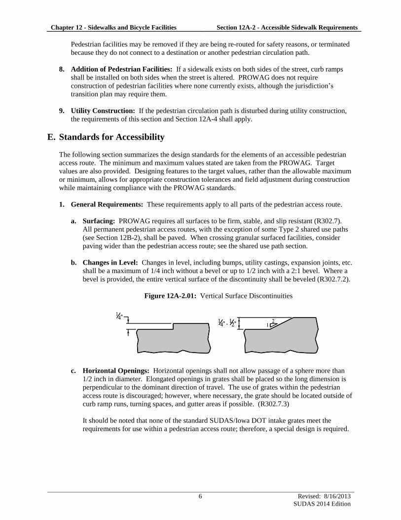
c. Horizontal Openings: Horizontal openings shall not allow passage of a sphere more than
1/2 inch in diameter. Elongated openings in grates shall be placed so the long dimension is
perpendicular to the dominant direction of travel. The use of grates within the pedestrian
access route is discouraged; however, where necessary, the grate should be located outside of
curb ramp runs, turning spaces, and gutter areas if possible. (R302.7.3)
It should be noted that none of the standard SUDAS/Iowa DOT intake grates meet the
requirements for use within a pedestrian access route; therefore, a special design is required.
Chapter 12 - Sidewalks and Bicycle Facilities Section 12A-2 - Accessible Sidewalk Requirements
7 Revised: 8/16/2013
SUDAS 2014 Edition
Figure 12A-2.02: Horizontal Openings
2. Standard Sidewalk: Sidewalks solely serving private residences are not required to follow these
requirements.
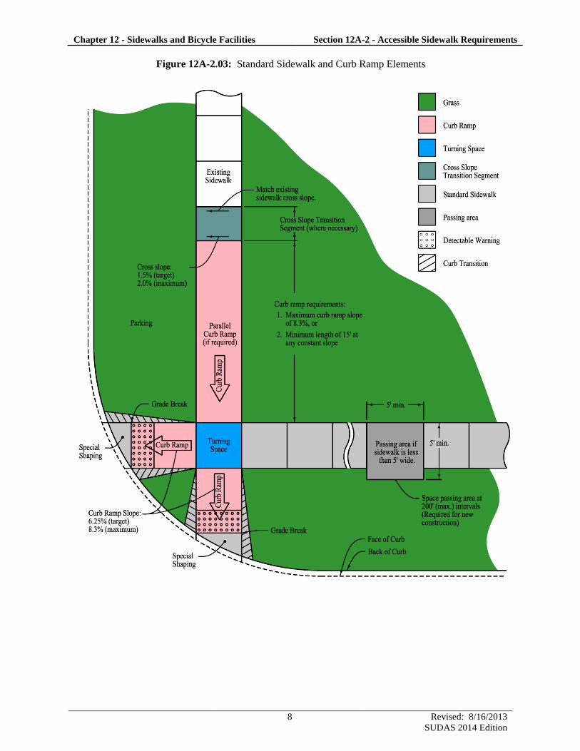
a. Cross Slope: The maximum cross slope is 2.0% with a target value of 1.5% (R302.6).
b. Running Slope: Sidewalks with a running slope of 5% or less are acceptable. However,
where the sidewalk is contained within the street right-of-way, the grade of the sidewalk shall
not exceed the general grade of the adjacent street (R302.5). For design, consider the general
grade of the adjacent street to be within approximately 2% of the profile grade of the street.
c. Width: The minimum width of the pedestrian access route is 4 feet. Five foot sidewalks are
encouraged and may be required by the Jurisdiction. Iowa DOT will design 5 foot sidewalks
unless otherwise requested. (R302.3)
d. Passing Spaces: Where the clear width of the pedestrian access route is less than 5 feet,
passing spaces are required at maximum intervals of 200 feet. The passing space shall be 5
foot minimum by 5 foot minimum. Passing spaces may overlap with the pedestrian access
route. (R302.4). Driveways may be used as passing spaces, as long as the 2.0% maximum
cross slope is not exceeded.
Chapter 12 - Sidewalks and Bicycle Facilities Section 12A-2 - Accessible Sidewalk Requirements
8 Revised: 8/16/2013
SUDAS 2014 Edition
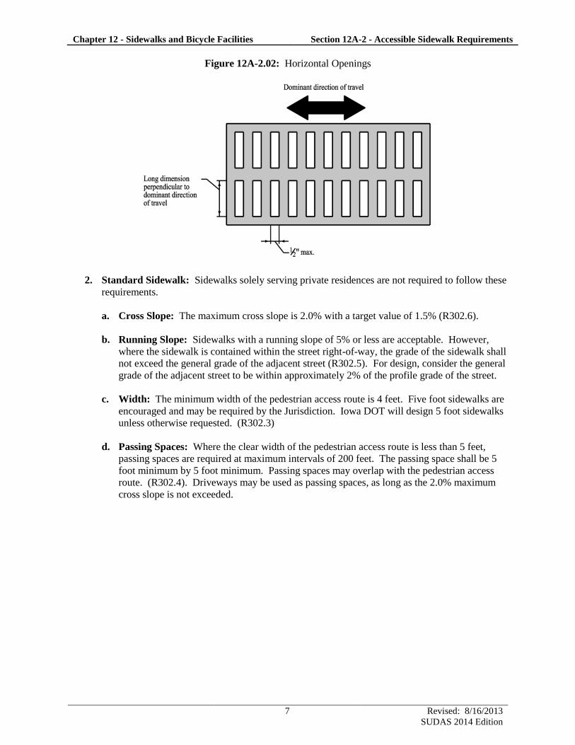
Figure 12A-2.03: Standard Sidewalk and Curb Ramp Elements
Chapter 12 - Sidewalks and Bicycle Facilities Section 12A-2 - Accessible Sidewalk Requirements
9 Revised: 8/16/2013
SUDAS 2014 Edition
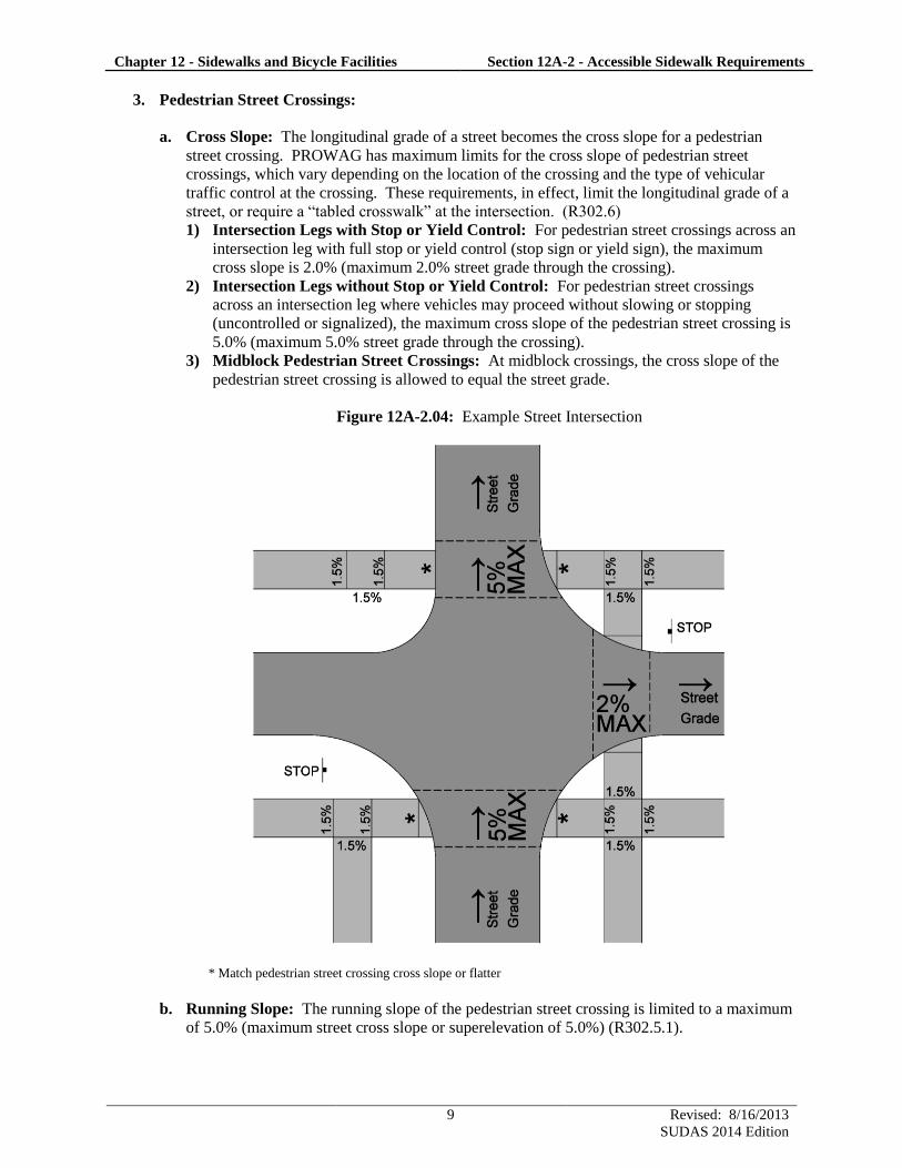
3. Pedestrian Street Crossings:
a. Cross Slope: The longitudinal grade of a street becomes the cross slope for a pedestrian
street crossing. PROWAG has maximum limits for the cross slope of pedestrian street
crossings, which vary depending on the location of the crossing and the type of vehicular
traffic control at the crossing. These requirements, in effect, limit the longitudinal grade of a
street, or require a “tabled crosswalk” at the intersection. (R302.6)
1) Intersection Legs with Stop or Yield Control: For pedestrian street crossings across an
intersection leg with full stop or yield control (stop sign or yield sign), the maximum
cross slope is 2.0% (maximum 2.0% street grade through the crossing).
2) Intersection Legs without Stop or Yield Control: For pedestrian street crossings
across an intersection leg where vehicles may proceed without slowing or stopping
(uncontrolled or signalized), the maximum cross slope of the pedestrian street crossing is
5.0% (maximum 5.0% street grade through the crossing).
3) Midblock Pedestrian Street Crossings: At midblock crossings, the cross slope of the
pedestrian street crossing is allowed to equal the street grade.
Figure 12A-2.04: Example Street Intersection
* Match pedestrian street crossing cross slope or flatter
b. Running Slope: The running slope of the pedestrian street crossing is limited to a maximum
of 5.0% (maximum street cross slope or superelevation of 5.0%) (R302.5.1).
Chapter 12 - Sidewalks and Bicycle Facilities Section 12A-2 - Accessible Sidewalk Requirements
10 Revised: 8/16/2013
SUDAS 2014 Edition
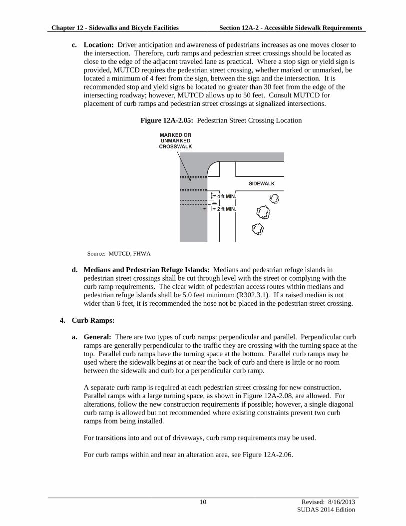
c. Location: Driver anticipation and awareness of pedestrians increases as one moves closer to
the intersection. Therefore, curb ramps and pedestrian street crossings should be located as
close to the edge of the adjacent traveled lane as practical. Where a stop sign or yield sign is
provided, MUTCD requires the pedestrian street crossing, whether marked or unmarked, be
located a minimum of 4 feet from the sign, between the sign and the intersection. It is
recommended stop and yield signs be located no greater than 30 feet from the edge of the
intersecting roadway; however, MUTCD allows up to 50 feet. Consult MUTCD for
placement of curb ramps and pedestrian street crossings at signalized intersections.
Figure 12A-2.05: Pedestrian Street Crossing Location
Source: MUTCD, FHWA
d. Medians and Pedestrian Refuge Islands: Medians and pedestrian refuge islands in
pedestrian street crossings shall be cut through level with the street or complying with the
curb ramp requirements. The clear width of pedestrian access routes within medians and
pedestrian refuge islands shall be 5.0 feet minimum (R302.3.1). If a raised median is not
wider than 6 feet, it is recommended the nose not be placed in the pedestrian street crossing.
4. Curb Ramps:
a. General: There are two types of curb ramps: perpendicular and parallel. Perpendicular curb
ramps are generally perpendicular to the traffic they are crossing with the turning space at the
top. Parallel curb ramps have the turning space at the bottom. Parallel curb ramps may be
used where the sidewalk begins at or near the back of curb and there is little or no room
between the sidewalk and curb for a perpendicular curb ramp.
A separate curb ramp is required at each pedestrian street crossing for new construction.
Parallel ramps with a large turning space, as shown in Figure 12A-2.08, are allowed. For
alterations, follow the new construction requirements if possible; however, a single diagonal
curb ramp is allowed but not recommended where existing constraints prevent two curb
ramps from being installed.
For transitions into and out of driveways, curb ramp requirements may be used.
For curb ramps within and near an alteration area, see Figure 12A-2.06.
Chapter 12 - Sidewalks and Bicycle Facilities Section 12A-2 - Accessible Sidewalk Requirements
11 Revised: 8/16/2013
SUDAS 2014 Edition
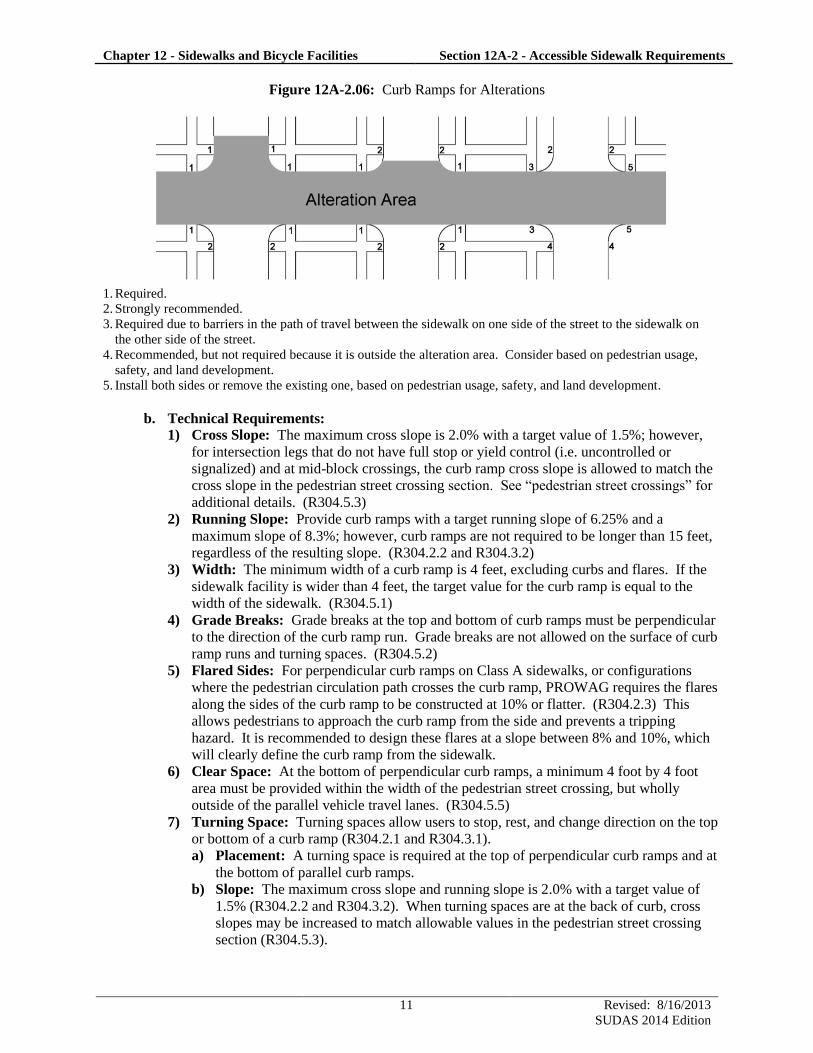
Figure 12A-2.06: Curb Ramps for Alterations
1. Required.
2. Strongly recommended.
3. Required due to barriers in the path of travel between the sidewalk on one side of the street to the sidewalk on
the other side of the street.
4. Recommended, but not required because it is outside the alteration area. Consider based on pedestrian usage,
safety, and land development.
5. Install both sides or remove the existing one, based on pedestrian usage, safety, and land development.
b. Technical Requirements:
1) Cross Slope: The maximum cross slope is 2.0% with a target value of 1.5%; however,
for intersection legs that do not have full stop or yield control (i.e. uncontrolled or
signalized) and at mid-block crossings, the curb ramp cross slope is allowed to match the
cross slope in the pedestrian street crossing section. See “pedestrian street crossings” for
additional details. (R304.5.3)
2) Running Slope: Provide curb ramps with a target running slope of 6.25% and a
maximum slope of 8.3%; however, curb ramps are not required to be longer than 15 feet,
regardless of the resulting slope. (R304.2.2 and R304.3.2)
3) Width: The minimum width of a curb ramp is 4 feet, excluding curbs and flares. If the
sidewalk facility is wider than 4 feet, the target value for the curb ramp is equal to the
width of the sidewalk. (R304.5.1)
4) Grade Breaks: Grade breaks at the top and bottom of curb ramps must be perpendicular
to the direction of the curb ramp run. Grade breaks are not allowed on the surface of curb
ramp runs and turning spaces. (R304.5.2)
5) Flared Sides: For perpendicular curb ramps on Class A sidewalks, or configurations
where the pedestrian circulation path crosses the curb ramp, PROWAG requires the flares
along the sides of the curb ramp to be constructed at 10% or flatter. (R304.2.3) This
allows pedestrians to approach the curb ramp from the side and prevents a tripping
hazard. It is recommended to design these flares at a slope between 8% and 10%, which
will clearly define the curb ramp from the sidewalk.
6) Clear Space: At the bottom of perpendicular curb ramps, a minimum 4 foot by 4 foot
area must be provided within the width of the pedestrian street crossing, but wholly
outside of the parallel vehicle travel lanes. (R304.5.5)
7) Turning Space: Turning spaces allow users to stop, rest, and change direction on the top
or bottom of a curb ramp (R304.2.1 and R304.3.1).
a) Placement: A turning space is required at the top of perpendicular curb ramps and at
the bottom of parallel curb ramps.
b) Slope: The maximum cross slope and running slope is 2.0% with a target value of
1.5% (R304.2.2 and R304.3.2). When turning spaces are at the back of curb, cross
slopes may be increased to match allowable values in the pedestrian street crossing
section (R304.5.3).

Chapter 12 - Sidewalks and Bicycle Facilities Section 12A-2 - Accessible Sidewalk Requirements
12 Revised: 8/16/2013
SUDAS 2014 Edition
c) Size: The turning space shall be a minimum of 4 feet by 4 feet. Where the turning
space is constrained on one or more sides, provide 5 feet in the direction of the
pedestrian street crossing.
8) Special Shaping Area: Transition area between the back of curb and the grade break.
The longest side cannot exceed 5 feet.
Figure 12A-2.07: Curb Ramp Turning Spaces
c. Curb Ramp Design Considerations:
1) Combination Curb Ramps: For many intersection configurations, a perpendicular curb
ramp will not provide enough length to establish the top turning space at the sidewalk
elevation; in these situations, a parallel curb ramp is often required to transition from the
turning space up to the sidewalk elevation. The use of a perpendicular curb ramp from
the curb to the turning space in conjunction with a parallel curb ramp between the turning
space and the sidewalk elevation is referred to as a combination curb ramp. When
transitioning from a turning space to sidewalk elevation on a steep street, it is not
necessary to chase the grade. As noted in the technical requirements above, a parallel
curb ramp is not required to exceed 15 feet in length, regardless of the resulting curb
ramp slope. In practice, the parallel curb ramp should be extended to the next joint
beyond 15 feet.
2) Cross Slope Transition Segment: When connecting to existing construction that is out
of cross slope compliance, the cross slope transition should be completed beyond the
parallel curb ramp or turning space; this recommendation eliminates the need to list this
curb ramp in the transition plan. It is recommended this cross slope transition take place
at 1% per foot or less. Typically, this can be accomplished in a single panel.
3) Parking Slope: In situations where the length of the perpendicular curb ramp is
insufficient to bring the turning space up to sidewalk elevation, consider lowering the
sidewalk and flattening the parking slope.
Chapter 12 - Sidewalks and Bicycle Facilities Section 12A-2 - Accessible Sidewalk Requirements
13 Revised: 8/16/2013
SUDAS 2014 Edition
5. Blended Transitions: A blended transition is allowed but not recommended. Design and
constructability is difficult to meet compliance requirements. In lieu of a blended transition, a
curb ramp or standard sidewalk should be used.
6. Detectable Warnings:
a. General: Detectable warning surfaces are detected underfoot or with a cane by blind and
low vision individuals. The warnings indicate the location of the back of curb. Detectable
warnings also provide a visual queue to pedestrians with low vision and aid in locating the
curb ramp across the street. For these reasons, the detectable warning shall contrast visually
(light on dark or dark on light) from the surrounding paved surfaces (R305.1.3).
b. Location: Detectable warnings shall be installed at all pedestrian street crossings and at-
grade rail crossings (R208.1). Detectable warning surfaces should not be provided at
crossings of residential driveways since the pedestrian right-of-way continues across the
driveway. Where commercial driveways are provided with yield control, stop control, or
traffic signals at the pedestrian access route, detectable warnings should be installed at the
junction between the pedestrian access route and the driveway (Advisory R208.1).
c. Size: Detectable warning surfaces shall extend a minimum of 2 feet in the direction of
pedestrian travel and extend the full width of the curb ramp or pedestrian access route
(R305.1.4).
d. Dome Orientation: On curb ramps, the rows of truncated domes should be aligned
perpendicular to the grade break so pedestrians in wheelchairs can track their wheels between
the domes. On surfaces less than 5% slope, dome orientation is less critical.
e. Parallel Curb Ramps: On parallel curb ramps, detectable warning shall be placed on the
turning space at the back of curb (R305.2.2).
Chapter 12 - Sidewalks and Bicycle Facilities Section 12A-2 - Accessible Sidewalk Requirements
14 Revised: 8/16/2013
SUDAS 2014 Edition
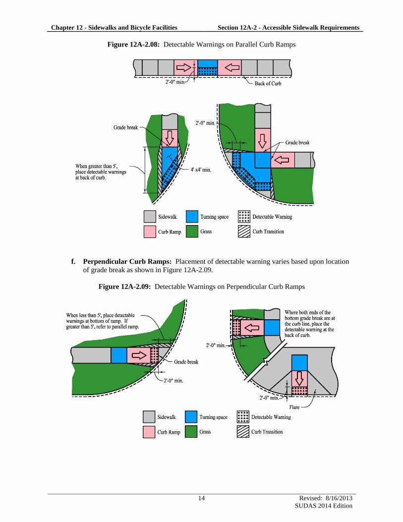
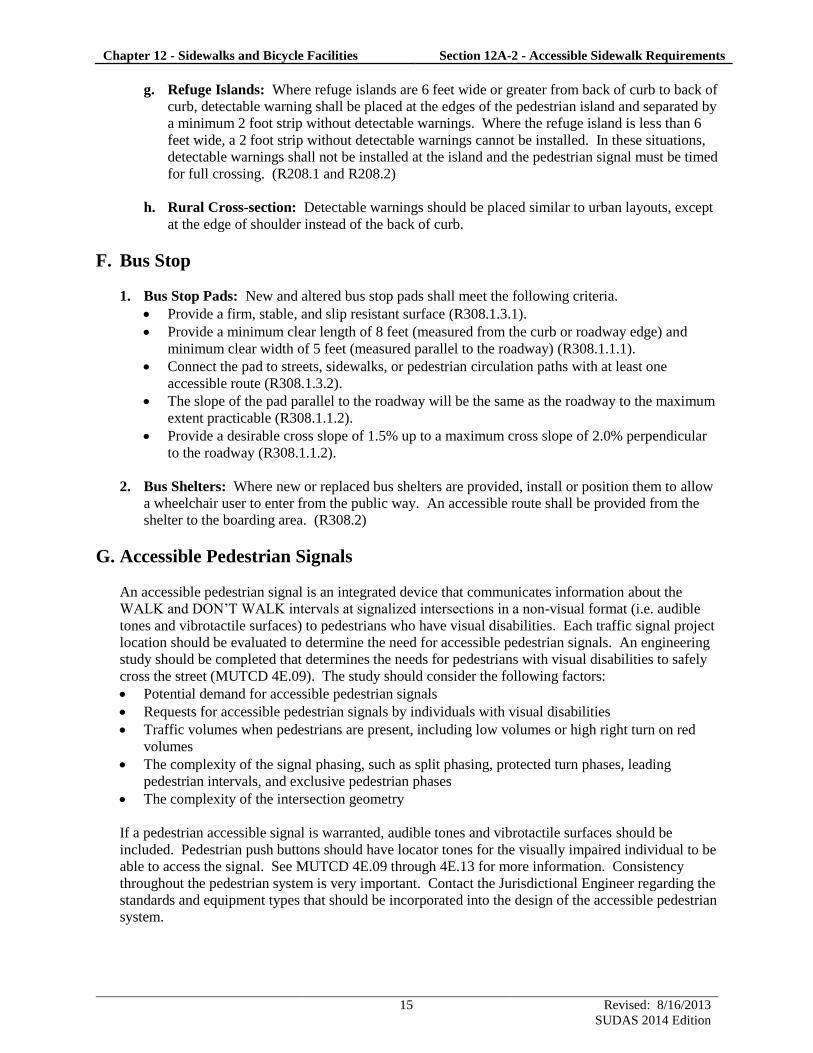
Figure 12A-2.08: Detectable Warnings on Parallel Curb Ramps
f. Perpendicular Curb Ramps: Placement of detectable warning varies based upon location
of grade break as shown in Figure 12A-2.09.
Figure 12A-2.09: Detectable Warnings on Perpendicular Curb Ramps
Chapter 12 - Sidewalks and Bicycle Facilities Section 12A-2 - Accessible Sidewalk Requirements
15 Revised: 8/16/2013
SUDAS 2014 Edition
g. Refuge Islands: Where refuge islands are 6 feet wide or greater from back of curb to back of
curb, detectable warning shall be placed at the edges of the pedestrian island and separated by
a minimum 2 foot strip without detectable warnings. Where the refuge island is less than 6
feet wide, a 2 foot strip without detectable warnings cannot be installed. In these situations,
detectable warnings shall not be installed at the island and the pedestrian signal must be timed
for full crossing. (R208.1 and R208.2)
h. Rural Cross-section: Detectable warnings should be placed similar to urban layouts, except
at the edge of shoulder instead of the back of curb.
F. Bus Stop
1. Bus Stop Pads: New and altered bus stop pads shall meet the following criteria.
Provide a firm, stable, and slip resistant surface (R308.1.3.1).
Provide a minimum clear length of 8 feet (measured from the curb or roadway edge) and
minimum clear width of 5 feet (measured parallel to the roadway) (R308.1.1.1).
Connect the pad to streets, sidewalks, or pedestrian circulation paths with at least one
accessible route (R308.1.3.2).
The slope of the pad parallel to the roadway will be the same as the roadway to the maximum
extent practicable (R308.1.1.2).
Provide a desirable cross slope of 1.5% up to a maximum cross slope of 2.0% perpendicular
to the roadway (R308.1.1.2).
2. Bus Shelters: Where new or replaced bus shelters are provided, install or position them to allow
a wheelchair user to enter from the public way. An accessible route shall be provided from the
shelter to the boarding area. (R308.2)
G. Accessible Pedestrian Signals
An accessible pedestrian signal is an integrated device that communicates information about the
WALK and DON’T WALK intervals at signalized intersections in a non-visual format (i.e. audible
tones and vibrotactile surfaces) to pedestrians who have visual disabilities. Each traffic signal project
location should be evaluated to determine the need for accessible pedestrian signals. An engineering
study should be completed that determines the needs for pedestrians with visual disabilities to safely
cross the street (MUTCD 4E.09). The study should consider the following factors:
Potential demand for accessible pedestrian signals
Requests for accessible pedestrian signals by individuals with visual disabilities
Traffic volumes when pedestrians are present, including low volumes or high right turn on red
volumes
The complexity of the signal phasing, such as split phasing, protected turn phases, leading
pedestrian intervals, and exclusive pedestrian phases
The complexity of the intersection geometry
If a pedestrian accessible signal is warranted, audible tones and vibrotactile surfaces should be
included. Pedestrian push buttons should have locator tones for the visually impaired individual to be
able to access the signal. See MUTCD 4E.09 through 4E.13 for more information. Consistency
throughout the pedestrian system is very important. Contact the Jurisdictional Engineer regarding the
standards and equipment types that should be incorporated into the design of the accessible pedestrian
system.

12A-3
Design Manual
Chapter 12 - Sidewalks and Bicycle Facilities
12A - Sidewalks
1 Revised: 9/20/2012
SUDAS 2013 Edition
Protruding Objects
A. Introduction
This section provides guidance to comply with section R402 of PROWAG. The pedestrian area is
any prepared area available for pedestrians (equivalent to the pedestrian circulation path as defined in
PROWAG). A protruding object is any obstacle that reduces the clearance width and/or the clearance
height within a pedestrian area. The pedestrian area is not limited to the sidewalk or the pedestrian
access route intended by the designer. The pedestrian area includes any areas that may be perceived
as a pedestrian walking space, including adjacent parking lots and paved frontage.
Common protruding objects include:
Signs and Sign poles Trash cans Fire hydrants
Landscaping and branches Transit shelters Parking meters
Utility boxes or poles and their stabilizing wires Bike racks Benches
Mailboxes (public and private) Planters Public Art
B. Protruding Object Locations
1. Outside the Pedestrian Area: A protruding object can result in narrow passing spaces, reduced
access, and injury. Therefore, protruding objects should be placed completely outside of the
pedestrian area whenever possible.
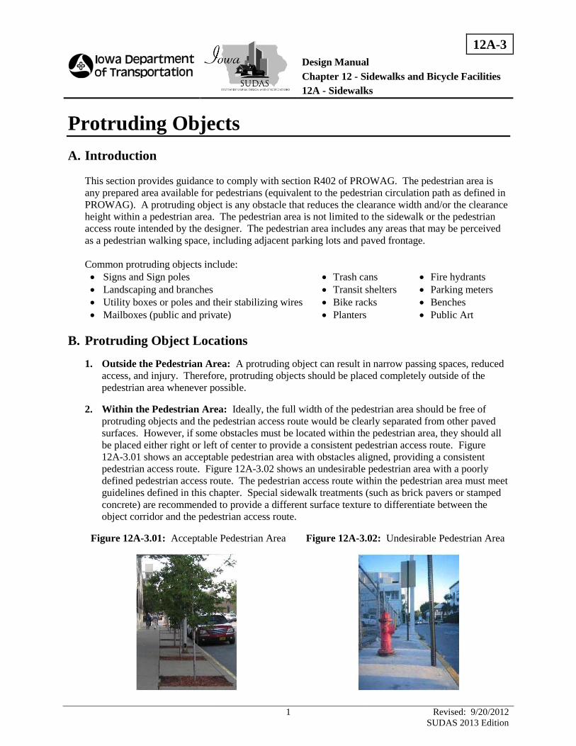
2. Within the Pedestrian Area: Ideally, the full width of the pedestrian area should be free of
protruding objects and the pedestrian access route would be clearly separated from other paved
surfaces. However, if some obstacles must be located within the pedestrian area, they should all
be placed either right or left of center to provide a consistent pedestrian access route. Figure
12A-3.01 shows an acceptable pedestrian area with obstacles aligned, providing a consistent
pedestrian access route. Figure 12A-3.02 shows an undesirable pedestrian area with a poorly
defined pedestrian access route. The pedestrian access route within the pedestrian area must meet
guidelines defined in this chapter. Special sidewalk treatments (such as brick pavers or stamped
concrete) are recommended to provide a different surface texture to differentiate between the
object corridor and the pedestrian access route.
Figure 12A-3.01: Acceptable Pedestrian Area Figure 12A-3.02: Undesirable Pedestrian Area
Chapter 12 - Sidewalks and Bicycle Facilities Section 12A-3 - Protruding Objects
2 Revised: 9/20/2012
SUDAS 2013 Edition
C. Clearance
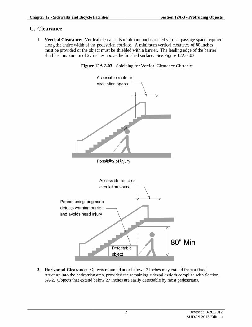
1. Vertical Clearance: Vertical clearance is minimum unobstructed vertical passage space required
along the entire width of the pedestrian corridor. A minimum vertical clearance of 80 inches
must be provided or the object must be shielded with a barrier. The leading edge of the barrier
shall be a maximum of 27 inches above the finished surface. See Figure 12A-3.03.
Figure 12A-3.03: Shielding for Vertical Clearance Obstacles
2. Horizontal Clearance: Objects mounted at or below 27 inches may extend from a fixed
structure into the pedestrian area, provided the remaining sidewalk width complies with Section
8A-2. Objects that extend below 27 inches are easily detectable by most pedestrians.
Chapter 12 - Sidewalks and Bicycle Facilities Section 12A-3 - Protruding Objects
3 Revised: 9/20/2012
SUDAS 2013 Edition
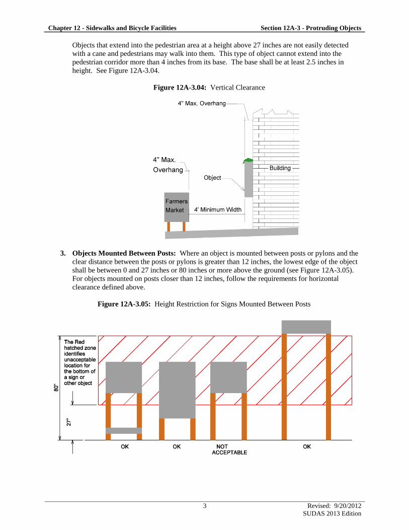
Objects that extend into the pedestrian area at a height above 27 inches are not easily detected
with a cane and pedestrians may walk into them. This type of object cannot extend into the
pedestrian corridor more than 4 inches from its base. The base shall be at least 2.5 inches in
height. See Figure 12A-3.04.
Figure 12A-3.04: Vertical Clearance
3. Objects Mounted Between Posts: Where an object is mounted between posts or pylons and the
clear distance between the posts or pylons is greater than 12 inches, the lowest edge of the object
shall be between 0 and 27 inches or 80 inches or more above the ground (see Figure 12A-3.05).
For objects mounted on posts closer than 12 inches, follow the requirements for horizontal
clearance defined above.
Figure 12A-3.05: Height Restriction for Signs Mounted Between Posts

12A-4
Design Manual
Chapter 12 - Sidewalks and Bicycle Facilities
12A - Sidewalks
1 Revised: 9/20/2012
SUDAS 2013 Edition
Pedestrian Facilities During Construction
A. Introduction
When projects impact pedestrians, it is important for the engineer to develop a temporary traffic
control plan for pedestrians, including those with disabilities. For Iowa DOT projects, see Iowa DOT
Design Manual Section 9A-5 for temporary traffic control plans. The applicable guidelines for the
temporary traffic control plan are the July 26, 2011 “Proposed Accessibility Guidelines for Pedestrian
Facilities in the Public Right-of-Way” (PROWAG) and the Manual on Uniform Traffic Control
Devices (MUTCD).
According to PROWAG, when a pedestrian circulation path is temporarily closed for construction or
maintenance activities, an alternate pedestrian access route complying with sections 6D.01, 6D.02,
and 6G.05 of the MUTCD shall be provided (R205). However, MUTCD (Section 6D.01) also
requires knowledgeable persons to conduct appropriate evaluations or use engineering judgment in
determining temporary traffic controls for pedestrian circulation paths. This section includes
guidance on conducting the evaluation when an alternate pedestrian access route may not be practical.
B. Evaluating Pedestrian Needs
The initial design activity should be to determine the level of the accessibility of the current
pedestrian circulation path within the area of the project and the adjacent areas. The impact to the
pedestrian circulation path, including transit stops, from the construction or maintenance activity
needs to be determined. Develop pedestrian accommodations to provide the best accessibility
practical through all stages of work. Consider obtaining local input through a public meeting or
contact with residents or public officials to see where additional accessibility needs should be
addressed (e.g. senior centers, medical facilities, schools, public facilities, etc.).
Whenever possible, the work should be done in such a manner that does not create a need to detour
pedestrians from existing routes. Pedestrians rarely observe detours and the cost of providing
accessibility and detectability might outweigh the cost of maintaining a continuous route through the
construction zone (MUTCD 6D-01). All methods should be given consideration, including providing
alternate means of traversing the construction zone. If pedestrians are to be directed through the
construction zone, safety as well as accessibility must be addressed. If a pedestrian detour is
developed, it should replicate the accessibility of the existing route.
C. Facility Options
To address the impacts to the pedestrian circulation path, including transit stops, consider the
following:
Develop a temporary traffic control plan to guide the pedestrians through the construction zone.
Close the pedestrian circulation path through the construction zone.
Close the pedestrian circulation path through the construction zone; develop a detour route
consistent with the accessibility features present in the pedestrian circulation path being closed.
Provide alternate means for pedestrians to traverse the construction zone, such as free accessible
shuttles or other forms of assistance.
Chapter 12 - Sidewalks and Bicycle Facilities Section 12A-4 - Pedestrian Facilities During Construction
2 Revised: 9/20/2012
SUDAS 2013 Edition
D. Barricades, Channelizing Devices, and Signs
Pedestrian barricades and channelizing devices shall comply with sections 6F.63, 6F.68, and 6F.71 of
the MUTCD.
1. Barricades: Barricades are used for pedestrian circulation path closures. See Iowa DOT
Specifications Section 2528.
2. Channelizing Devices: The designer should consider the safety of pedestrians and vehicles
when choosing channelizing devices.
a. Type A: Type A devices are redirective barriers designed for highway applications. These
devices are suitable when pedestrians are routed into the travel way and allow for the most
protection for pedestrians from vehicular intrusion.
b. Type B: Type B devices are crashworthy but do not redirect vehicles. These devices are
designed to minimize risks associated with flying debris.
c. Type C: Type C devices include any device that meets ADA requirements for channelizing
pedestrians and may not be crashworthy. These devices are for locations where vehicular
intrusions are unlikely (e.g. closed roads, when there is a separation between pedestrians and
vehicular traffic, or where vehicular traffic is at low speeds).
3. Signs: See Iowa DOT Standard Road Plan TC-601 and TC-602.
E. Temporary Pedestrian Facilities
Temporary pedestrian facilities should comply with the other sections within this chapter to the extent
practical. It is strongly recommended that detour routes be on paved surfaces.
Temporary pedestrian facility surfaces must be firm, stable, and slip resistant. Granular surfacing for
short term, temporary pedestrian facilities is acceptable. The granular surfacing material should be
well graded, such as Class A road stone (Iowa DOT Specifications Section 4196, Gradation No. 8) or
special backfill (Iowa DOT Specifications Section 4196, Gradation No. 30). Maintenance of the
temporary pedestrian facility surface to meet the firm, stable, slip resistant, and minimum width is
required at all times. The temporary pedestrian facility surface must be removed and a permanent
pedestrian facility must be replaced prior to the end of the construction season.
F. Utility Construction
If the pedestrian circulation path is disturbed during utility construction, the requirements of this
section and Section 12A-2 shall apply.
12B-1
Design Manual
Chapter 12 - Sidewalks and Bicycle Facilities
12B - Bicycle Facilities
1 Revised: 9/20/2012
SUDAS 2013 Edition
Bicycle and Pedestrian Facilities
A. Introduction
There are four major categories for bicycle and pedestrian facilities: sidewalks, shared use paths, on-
street, and trails. Sidewalks are an integral component of the transportation system, usually used only
by pedestrians. For information on designing sidewalks, see Section 12A-1 and Section 12A-2.
Shared use paths are also an integral component of the transportation system and use the sidewalk
standards, but must also be designed for bicycle usage. Shared use paths are generally separate from
the street, but in limited instances it may be necessary to utilize an on-street facility.
The word “trail” has conflicting definitions in ADA, AASHTO, program funding, and common
usage. Projects developed around the state and those let through the Iowa DOT are generally shared
use paths as defined by the Access Board, not trails. Facilities with a transportation purpose cannot
use the trail guidelines published by the Access Board, even though they are commonly referred to as
trails. The trail information from the Access Board only applies in parks and other limited locations;
therefore, they are not covered in this manual.
B. Definitions
The following definitions are from the “AASHTO Guide for the Development of Bicycle Facilities”
(or AASHTO Bike Guide).
Bicycle Boulevard: A street segment, or series of contiguous street segments, that has been modified
to accommodate through bicycle traffic and minimize through motor traffic.
Bicycle Facilities: A general term denoting improvements and provisions to accommodate or
encourage bicycling, including parking and storage facilities, and shared roadways not specifically
defined for bicycle use.
Bicycle Lane or Bike Lane: A portion of roadway that has been designated for preferential or
exclusive use by bicyclists by pavement markings and, if used, signs. It is intended for one-way
travel, usually in the same direction as the adjacent traffic lane, unless designed as a contra-flow lane.
Bicycle Route: A roadway or bikeway designated by the jurisdiction having authority, either with a
unique route designation or with BIKE ROUTE signs, along which bicycle guide signs may provide
directional and distance information. Signs that provide directional, distance, and destination
information for bicyclists do not necessarily establish a bicycle route.
Bikeway: A generic term for any road, street, path, or way that in some matter is specifically
designated for bicycle travel, regardless of whether such facilities are designated for the exclusive use
of bicycles or are to be shared with other transportation modes.
Independent Right-of-Way: A general term denoting right-of-way outside the boundary of a
conventional highway.
Chapter 12 - Sidewalks and Bicycle Facilities Section 12B-1 - Bicycle and Pedestrian Facilities
2 Revised: 9/20/2012
SUDAS 2013 Edition
Roundabout: A type of circular intersection that provides yield control to all entering vehicles and
features channelized approaches and geometry to encourage reduced travel speeds through the
circular roadway.
Rumble Strips: A textured or grooved pavement treatment designed to create noise and vibration to
alert motorists of a need to change their path or speed. Longitudinal rumble strips are sometimes
used on or along shoulders or center lines of highways to alert motorists who stray from the
appropriate traveled way. Transverse rumble strips are placed on the roadway surface in the travel
lane, perpendicular to the direction of travel.
Shared Lane: A lane of a traveled way that is open to both bicycle and motor vehicle travel.
Shared Lane Marking: A pavement marking or symbol that indicates an appropriate bicycle
positioning in a shared lane.
Shared Use Path: (From U.S. Department of Transportation, Federal Highway Administration) The
term “shared use path” means a multi-use trail or other path, physically separated from motorized
vehicular traffic by an open space or barrier, either within a highway right-of-way or within an
independent right-of-way, and usable for transportation purposes. Shared use paths may be used by
pedestrians, bicyclists, skaters, equestrians, and other nonmotorized users.
Traveled Way: The portion of the roadway intended for the movement of vehicles, exclusive of
shoulders and any bike lane immediately inside of the shoulder.
C. Design Process
Comprehensive systematic design is necessary to ensure a useful shared use path or on-street bicycle
facility is provided for the public. To do this, the following items need to be addressed.
1. Identification of need of shared use path(s) and/or on-street bicycle system.
2. Determine objective of shared use path(s) and/or on-street bicycle facility.
3. Develop shared use path(s) and/or on-street bicycle facility potential use.
4. Route(s) evaluation, location, and selection:
Adequate access
Directness and convenience
Continuity with shared use path network
Attractiveness of route
Safety and security
Delays along route
Cost of improvements
Shared use of facility
Maintenance
Conflicts with other vehicles
Adequacy of street use
o Grades and geometrics
o Surface obstructions and conditions
o Traffic volumes and speeds
o Truck and bus traffic
o Parking
o Intersection conditions

Chapter 12 - Sidewalks and Bicycle Facilities Section 12B-1 - Bicycle and Pedestrian Facilities
3 Revised: 9/20/2012
SUDAS 2013 Edition
o Signing and pavement markings
o Sight distances
o Clearance (vertical and horizontal)
o Bridge and railroad crossings
5. Choosing an appropriate facility type. (Refer to AASHTO Bike Guide Exhibit 2.3 for more
information in selecting a facility type).
Shared lanes
Paved shoulders
Bike lanes
Bike boulevards
Shared use paths

12B-2
Design Manual
Chapter 12 - Sidewalks and Bicycle Facilities
12B - Bicycle Facilities
1 Revised: 9/20/2012
SUDAS 2013 Edition
Shared Use Path Design
A. Accessible Shared Use Path Design
1. General: Applicable portions from the following draft documents were used to develop this
section.
a. AASHTO Bike Guide: The fourth edition (2012) of the AASHTO “Guide for the
Development of Bicycle Facilities” (or AASHTO Bike Guide). References made to the
AASHTO Bike Guide within this section are shown in parentheses, e.g. (AASHTO 5.2.1).
b. AGODA: The June 20, 2007 Proposed Architectural Barriers Act “Accessibility Guidelines
for Outdoor Developed Areas” (AGODA). This document is primarily used for shared use
paths designed as bicycle facilities.
c. PROWAG: The July 26, 2011 “Proposed Accessibility Guidelines for Pedestrian Facilities
in the Public Right-of-Way,” also known as the Public Right-of-Way Accessibility
Guidelines or PROWAG. This document is primarily used for shared use paths designed as
sidewalks.
2. Documenting Exceptions: If the project cannot fully meet the minimum requirements included
within this section, a document should be developed to describe why the minimum requirements
cannot be met. It is recommended that this document be retained in the project file. For local
agency projects administered through Iowa DOT, a certification with supporting documentation
shall be submitted to the Iowa DOT administering office. The certification shall be as prescribed
by the Iowa DOT and signed by a registered professional engineer or landscape architect licensed
in the State of Iowa. For Iowa DOT projects, contact the Office of Design, Methods Section.
B. Shared Use Path Categories
1. Type 1: A shared use path adjacent or in close proximity to the roadway and functions similar to
a sidewalk. In rural cross-sections, these paths would be at the top of the foreslope. These paths
are generally used for transportation purposes.
2. Type 2: A shared use path similar to Type 3, except they serve as a transportation route to
facilities that fulfill a basic life need, provide access to a program or service, or provide a safe
route for non-drivers.
3. Type 3: A shared use path in independent right-of-way or not in close proximity to the roadway.
Although Type 3 paths may fulfill a transportation function, these paths primarily serve a
recreation and fitness benefit.
One shared use path project may have different combinations of Type 1, Type 2, and/or Type 3
segments, based on location and function. If Federal or State funding is being used on a project, the
funding application should identify where Type 1, Type 2, or Type 3 segments will be used.
Chapter 12 - Sidewalks and Bicycle Facilities Section 12B-2 - Shared Use Path Design
2 Revised: 9/20/2012
SUDAS 2013 Edition
C. Shared Use Path Design Elements
The following considerations should be used as a guide when designing shared use paths.
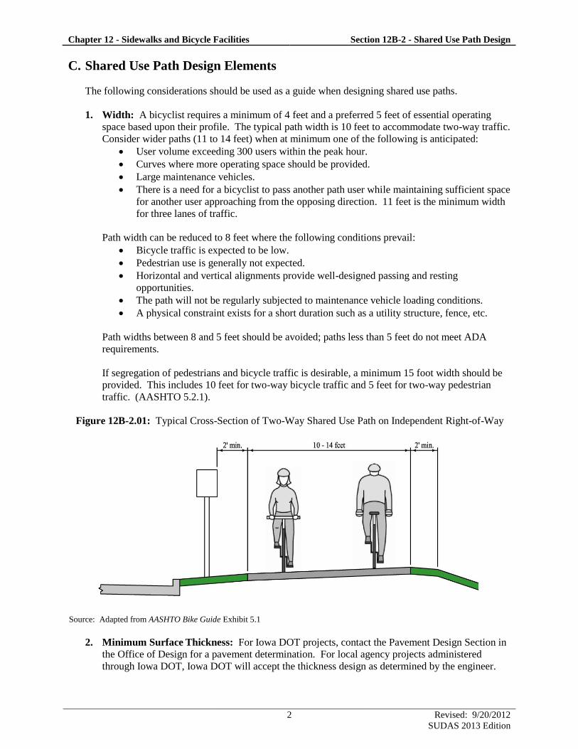
1. Width: A bicyclist requires a minimum of 4 feet and a preferred 5 feet of essential operating
space based upon their profile. The typical path width is 10 feet to accommodate two-way traffic.
Consider wider paths (11 to 14 feet) when at minimum one of the following is anticipated:
User volume exceeding 300 users within the peak hour.
Curves where more operating space should be provided.
Large maintenance vehicles.
There is a need for a bicyclist to pass another path user while maintaining sufficient space
for another user approaching from the opposing direction. 11 feet is the minimum width
for three lanes of traffic.
Path width can be reduced to 8 feet where the following conditions prevail:
Bicycle traffic is expected to be low.
Pedestrian use is generally not expected.
Horizontal and vertical alignments provide well-designed passing and resting
opportunities.
The path will not be regularly subjected to maintenance vehicle loading conditions.
A physical constraint exists for a short duration such as a utility structure, fence, etc.
Path widths between 8 and 5 feet should be avoided; paths less than 5 feet do not meet ADA
requirements.
If segregation of pedestrians and bicycle traffic is desirable, a minimum 15 foot width should be
provided. This includes 10 feet for two-way bicycle traffic and 5 feet for two-way pedestrian
traffic. (AASHTO 5.2.1).
Figure 12B-2.01: Typical Cross-Section of Two-Way Shared Use Path on Independent Right-of-Way
Source: Adapted from AASHTO Bike Guide Exhibit 5.1
2. Minimum Surface Thickness: For Iowa DOT projects, contact the Pavement Design Section in
the Office of Design for a pavement determination. For local agency projects administered
through Iowa DOT, Iowa DOT will accept the thickness design as determined by the engineer.
Chapter 12 - Sidewalks and Bicycle Facilities Section 12B-2 - Shared Use Path Design
3 Revised: 9/20/2012
SUDAS 2013 Edition
For local projects, the pavement depth for both PCC and HMA pavements should have a
minimum of 4 inches and a recommended thickness of 5 inches; if pavement thickness is
proposed to be less than 4 inches, a pavement determination should be completed and
documented.
3. Cross Slope: Shared use paths must have the capabilities to serve people with disabilities.
a. Type 1 and Type 2: Cross slopes shall not exceed the requirements in Section 12A-2.
b. Type 3: A 1.5% cross slope is recommended, but cross slopes should be a minimum of 1%
and shall not exceed 5%. Cross slopes greater than 2% should be sloped to the inside of the
horizontal curve regardless of drainage conditions. On unpaved paths, cross slopes may
increase up to 5% due to the need of draining water off the path. On rare bicycle only
facilities, the path does not need to meet accessibility guidelines and the cross slope can be
between 5% and 8%. Cross slope transition should be comfortable for the user; therefore, a
minimum transition length of 5 feet for each 1% change in cross slope should be used.
4. Separation of Roadway and Path: A separation should be provided between a two-way shared
use path and the adjacent roadway to demonstrate to both the bicyclist and the vehicle driver that
each facility is independent of the other. This is particularly important at night. If the separation
from the face of the curb or the edge of the traveled way to the near edge of the path is less than 5
feet, a barrier or railing is recommended. The barriers or railings need not be of the size and
strength to redirect errant motorists unless a crashworthy barrier is needed due to high speeds and
clear zone requirements. Barriers at other locations serving only as a separation should be the
height of standard guardrail.
If needed, barriers and railings should be used, but since they can create considerable concerns in
urban areas due to aesthetics, visibility, and maintenance problems, it may be necessary to initiate
the documenting exceptions process (Section 12B-2, A, 2). The separation between the face of
the curb and the path should be maximized, but with the presence of the curb, some landscaping
area, and street lighting, the overall objectives of the separation can be satisfied.
5. Lateral and Vertical Clearance: Perhaps the most critical factor in developing safe and
comfortable shared use path facilities is the provision of adequate clearance to a wide variety of
potential obstructions that may be found along a prospective route. Guidelines for lateral and
vertical clearance are particularly important in view of the wide range of riding proficiency that is
found among riders. Clearance consideration must include:
a. Lateral Clearances to Fixed and Movable Obstructions: A 2 foot minimum graded area
with a 6:1 maximum cross slope (i.e., shoulder area) should be provided for clearance from
lateral obstructions such as trees, poles, and bridge abutments measured from the edge of the
pathway. The MUTCD requires a 2 foot minimum clearance to the sign face of post-
mounted signs.
If a barrier or rail is necessary, a minimum of 1 foot lateral offset from the edge of the path is
desirable. Barriers terminating within 2 feet of the edge of the path should be marked with
object markers. It is undesirable to place the pathway in a narrow corridor between 2 fences
for long distances.
A designer may want to consider that a typical ambulance width (including mirrors) is 11
feet.
When minimum clearance cannot be achieved, refer to Section 12A-3 for protruding object
requirements; refer to the AASHTO Bike Guide for mitigation measures, such as pavement
markings, delineation, and signing.
Chapter 12 - Sidewalks and Bicycle Facilities Section 12B-2 - Shared Use Path Design
4 Revised: 9/20/2012
SUDAS 2013 Edition
b. Vertical Clearances to Overhead Obstructions: The minimum vertical clearance is 10
feet. In some situations, such as tunnels and bridge underpasses, the vertical clearance should
be greater than 10 feet in order to accommodate maintenance and emergency vehicles. In
constrained areas, AASHTO allows the vertical clearance to obstructions to be a minimum of
8 feet. (AASHTO 5.2.1).
Refer to Section 12A-3 for legal requirements in low clearance situations.
6. Shoulder Width and Slope: The minimum graded shoulder width is 2 feet. The maximum
shoulder area cross slope is 6:1.
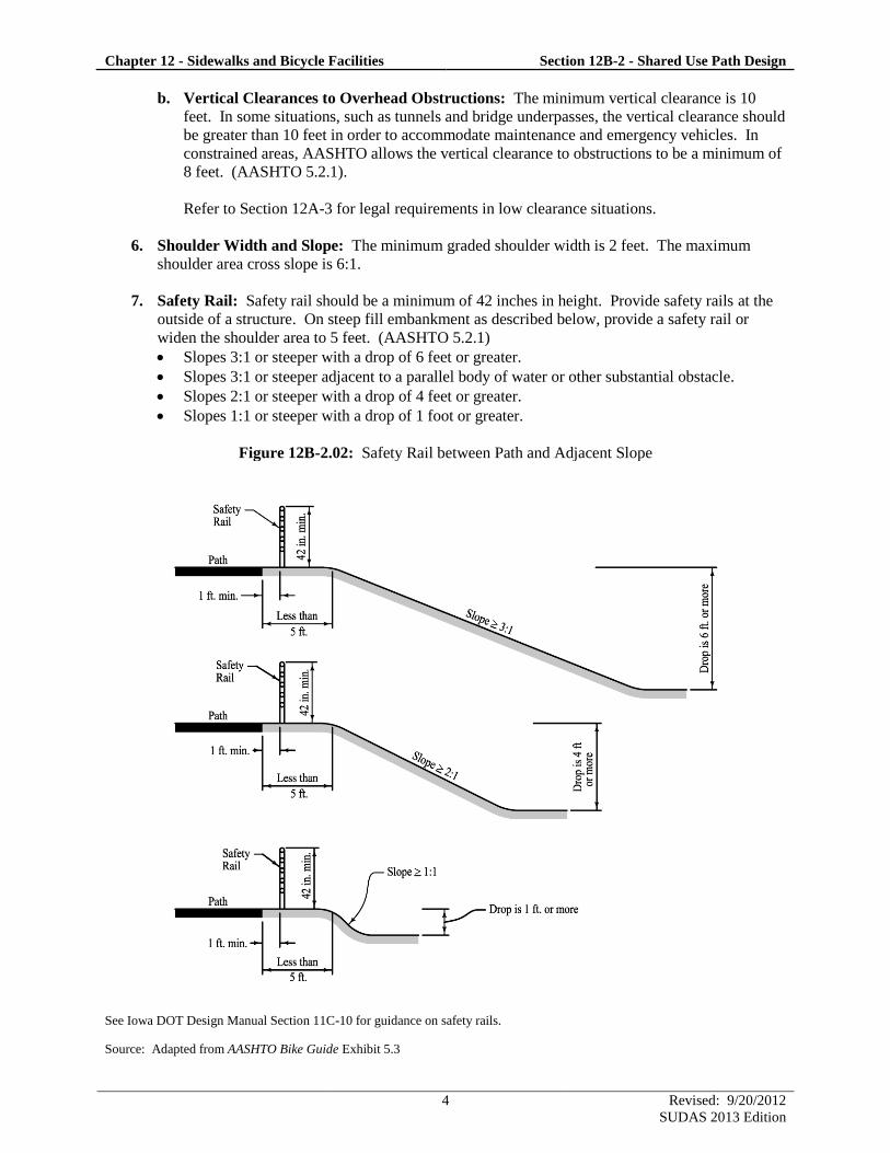
7. Safety Rail: Safety rail should be a minimum of 42 inches in height. Provide safety rails at the
outside of a structure. On steep fill embankment as described below, provide a safety rail or
widen the shoulder area to 5 feet. (AASHTO 5.2.1)
Slopes 3:1 or steeper with a drop of 6 feet or greater.
Slopes 3:1 or steeper adjacent to a parallel body of water or other substantial obstacle.
Slopes 2:1 or steeper with a drop of 4 feet or greater.
Slopes 1:1 or steeper with a drop of 1 foot or greater.
Figure 12B-2.02: Safety Rail between Path and Adjacent Slope
See Iowa DOT Design Manual Section 11C-10 for guidance on safety rails.
Source: Adapted from AASHTO Bike Guide Exhibit 5.3
Chapter 12 - Sidewalks and Bicycle Facilities Section 12B-2 - Shared Use Path Design
5 Revised: 9/20/2012
SUDAS 2013 Edition
8. Design Speed and Alignments:
a. Type 1: Grades shall meet the requirements of Section 12A-2.
b. Type 2: Grades shall be less than or equal to 5% and all other Type 3 requirements should be
met.
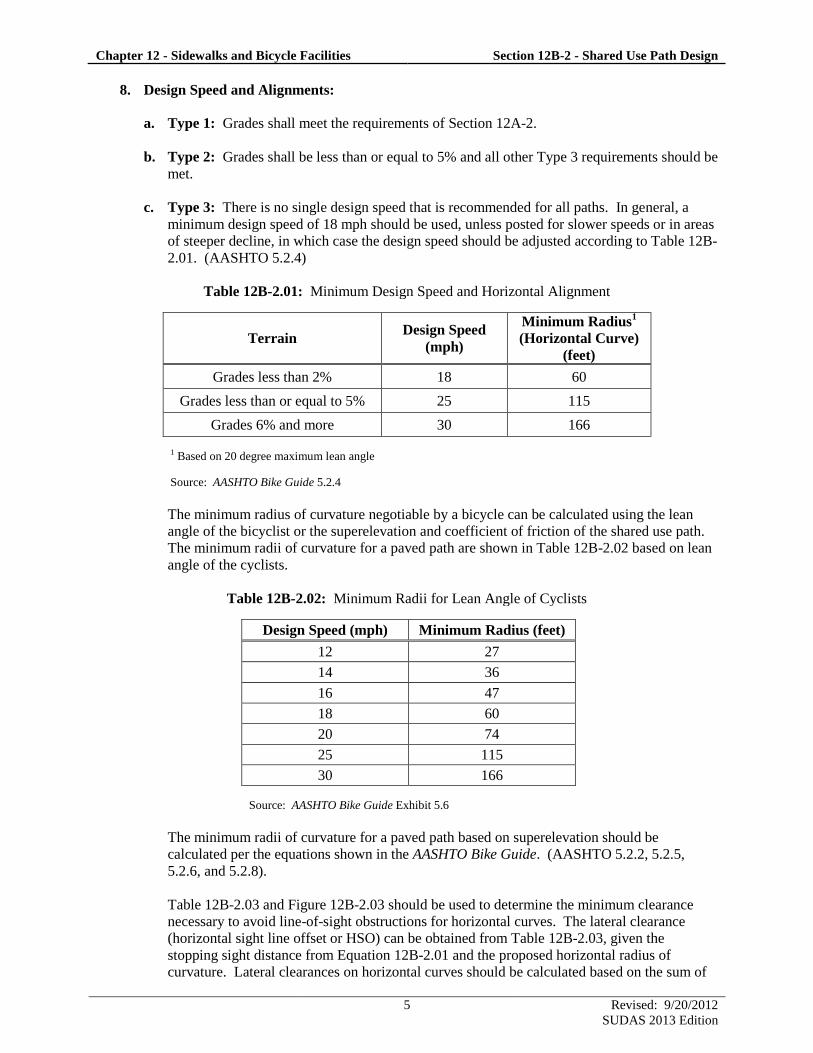
c. Type 3: There is no single design speed that is recommended for all paths. In general, a
minimum design speed of 18 mph should be used, unless posted for slower speeds or in areas
of steeper decline, in which case the design speed should be adjusted according to Table 12B-
2.01. (AASHTO 5.2.4)
Table 12B-2.01: Minimum Design Speed and Horizontal Alignment
Terrain Design Speed
(mph)
Minimum Radius1
(Horizontal Curve)
(feet)
Grades less than 2% 18 60
Grades less than or equal to 5% 25 115
Grades 6% and more 30 166
1 Based on 20 degree maximum lean angle
Source: AASHTO Bike Guide 5.2.4
The minimum radius of curvature negotiable by a bicycle can be calculated using the lean
angle of the bicyclist or the superelevation and coefficient of friction of the shared use path.
The minimum radii of curvature for a paved path are shown in Table 12B-2.02 based on lean
angle of the cyclists.
Table 12B-2.02: Minimum Radii for Lean Angle of Cyclists
Design Speed (mph) Minimum Radius (feet)
12 27
14 36
16 47
18 60
20 74
25 115
30 166
Source: AASHTO Bike Guide Exhibit 5.6
The minimum radii of curvature for a paved path based on superelevation should be
calculated per the equations shown in the AASHTO Bike Guide. (AASHTO 5.2.2, 5.2.5,
5.2.6, and 5.2.8).
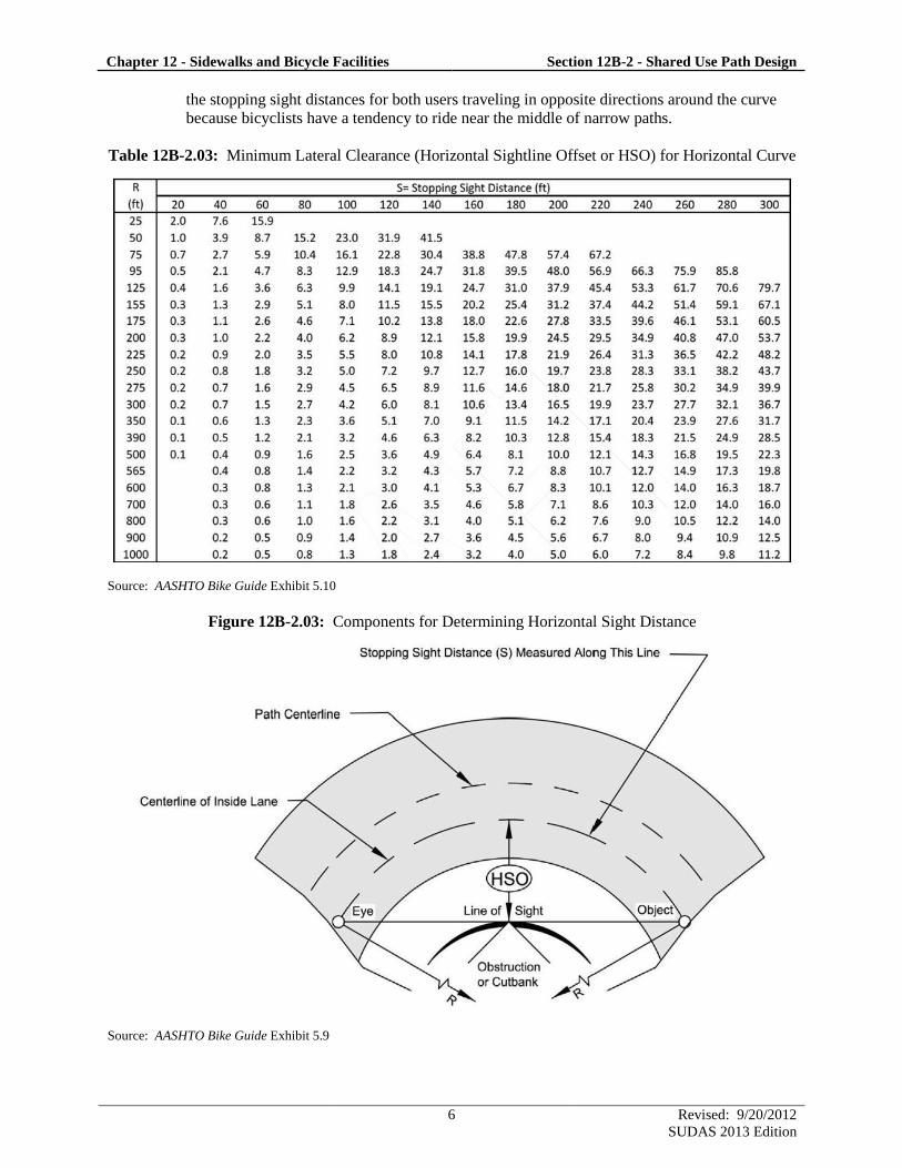
Table 12B-2.03 and Figure 12B-2.03 should be used to determine the minimum clearance
necessary to avoid line-of-sight obstructions for horizontal curves. The lateral clearance
(horizontal sight line offset or HSO) can be obtained from Table 12B-2.03, given the
stopping sight distance from Equation 12B-2.01 and the proposed horizontal radius of
curvature. Lateral clearances on horizontal curves should be calculated based on the sum of
Chapter 12 - Sidewalks and Bicycle Facilities Section 12B-2 - Shared Use Path Design
6 Revised: 9/20/2012
SUDAS 2013 Edition
the stopping sight distances for both users traveling in opposite directions around the curve
because bicyclists have a tendency to ride near the middle of narrow paths.
Table 12B-2.03: Minimum Lateral Clearance (Horizontal Sightline Offset or HSO) for Horizontal Curve
Source: AASHTO Bike Guide Exhibit 5.10
Figure 12B-2.03: Components for Determining Horizontal Sight Distance
Source: AASHTO Bike Guide Exhibit 5.9
Chapter 12 - Sidewalks and Bicycle Facilities Section 12B-2 - Shared Use Path Design
7 Revised: 9/20/2012
SUDAS 2013 Edition
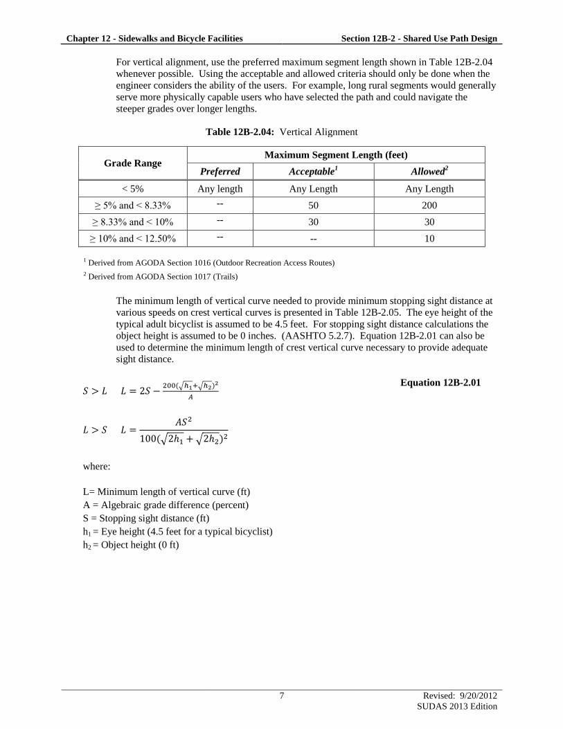
For vertical alignment, use the preferred maximum segment length shown in Table 12B-2.04
whenever possible. Using the acceptable and allowed criteria should only be done when the
engineer considers the ability of the users. For example, long rural segments would generally
serve more physically capable users who have selected the path and could navigate the
steeper grades over longer lengths.
Table 12B-2.04: Vertical Alignment
Grade Range Maximum Segment Length (feet)
Preferred Acceptable1 Allowed
2
< 5% Any length Any Length Any Length
≥ 5% and < 8.33% -- 50 200
≥ 8.33% and < 10% -- 30 30
≥ 10% and < 12.50% -- -- 10
1 Derived from AGODA Section 1016 (Outdoor Recreation Access Routes)
2 Derived from AGODA Section 1017 (Trails)
The minimum length of vertical curve needed to provide minimum stopping sight distance at
various speeds on crest vertical curves is presented in Table 12B-2.05. The eye height of the
typical adult bicyclist is assumed to be 4.5 feet. For stopping sight distance calculations the
object height is assumed to be 0 inches. (AASHTO 5.2.7). Equation 12B-2.01 can also be
used to determine the minimum length of crest vertical curve necessary to provide adequate
sight distance.
√ √
Equation 12B-2.01
√ √
where:
L= Minimum length of vertical curve (ft)
A = Algebraic grade difference (percent)
S = Stopping sight distance (ft)
h1 = Eye height (4.5 feet for a typical bicyclist)
h2 = Object height (0 ft)
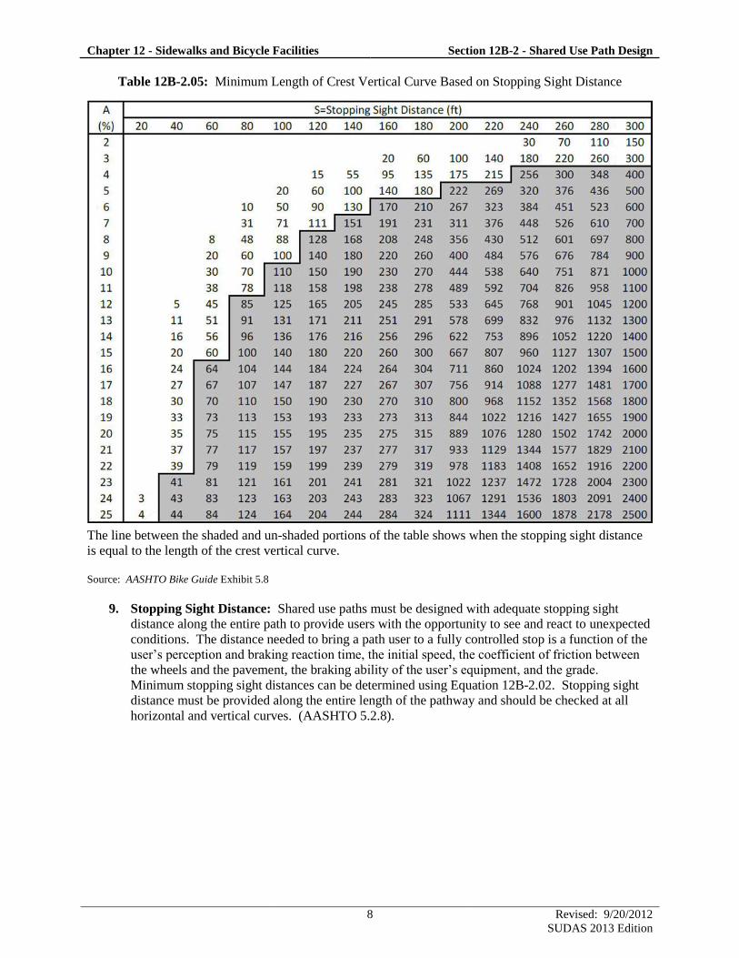
Chapter 12 - Sidewalks and Bicycle Facilities Section 12B-2 - Shared Use Path Design
8 Revised: 9/20/2012
SUDAS 2013 Edition
Table 12B-2.05: Minimum Length of Crest Vertical Curve Based on Stopping Sight Distance
The line between the shaded and un-shaded portions of the table shows when the stopping sight distance
is equal to the length of the crest vertical curve.
Source: AASHTO Bike Guide Exhibit 5.8
9. Stopping Sight Distance: Shared use paths must be designed with adequate stopping sight
distance along the entire path to provide users with the opportunity to see and react to unexpected
conditions. The distance needed to bring a path user to a fully controlled stop is a function of the
user’s perception and braking reaction time, the initial speed, the coefficient of friction between
the wheels and the pavement, the braking ability of the user’s equipment, and the grade.
Minimum stopping sight distances can be determined using Equation 12B-2.02. Stopping sight
distance must be provided along the entire length of the pathway and should be checked at all
horizontal and vertical curves. (AASHTO 5.2.8).
Chapter 12 - Sidewalks and Bicycle Facilities Section 12B-2 - Shared Use Path Design
9 Revised: 9/20/2012
SUDAS 2013 Edition
Equation 12B-2.02
where:
S = Stopping sight distance (ft)
V = Velocity (mph)
f = Coefficient of friction (use 0.16 for a typical bicycle)
G = Grade (ft/ft) (rise/run)
10. Accessibility Requirements: For construction of curb ramps and placement of detectable
warnings, see Section 12A-2 to ensure ADA compliance.
D. Intersection Sight Distance
1. General: Intersection sight distance is a fundamental component in the selection of appropriate
control at a midblock path-roadway intersection. The least restrictive control that is effective
should be used. The line of sight is considered to be 2.3 feet above the path surface.
Roadway approach sight distance and departure sight triangles should be calculated using motor
vehicles, which will control the design criteria. (AASHTO 5.3).
2. Approach Sight Distance: Pathway approach sight distance should be determined by the fastest
path user, typically the adult bicyclist. If yield control is to be used for either the roadway
approach or the path approach, available sight distance adequate for a traveler on the yield
controlled approach to slow, stop, and avoid a traveler on the other approach is required. The
roadway leg (a) of the sight triangle is based on the ability of a bicyclist to reach and cross the
roadway if they do not see a conflict (see Figure 12B-2.04). Similarly, the path leg (b) of the
sight triangle is based on the ability of a motorist to reach and cross the junction if they do not see
a conflict (see Figure 12B-2.04). If sufficient sight distance is unable to be provided by the yield
sight triangle described above, more restrictive control should be implemented.
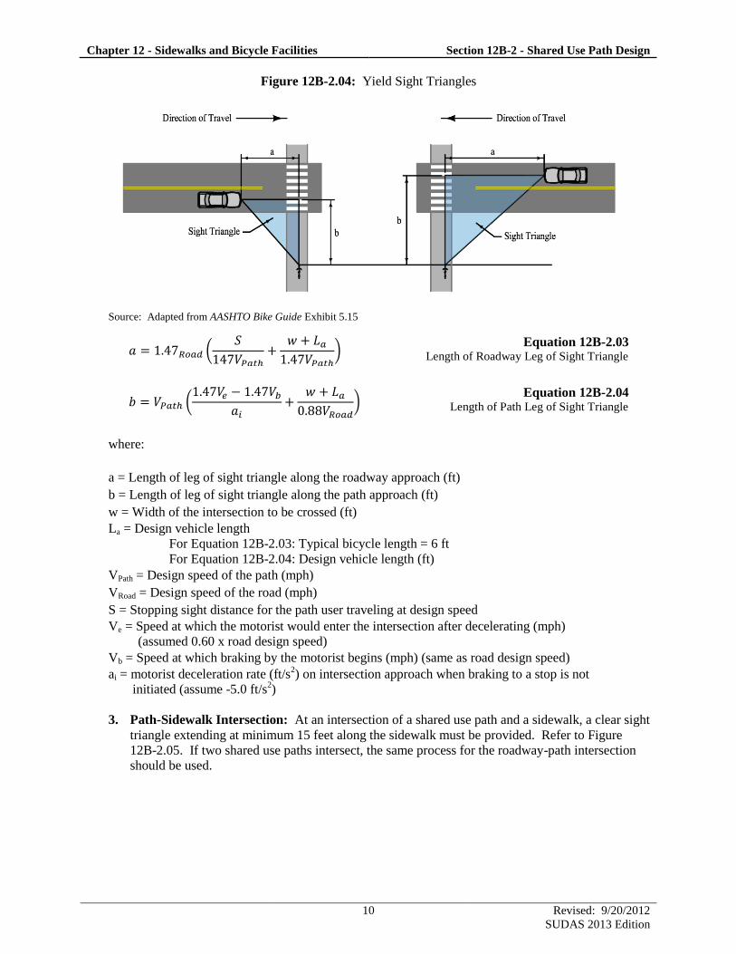
Chapter 12 - Sidewalks and Bicycle Facilities Section 12B-2 - Shared Use Path Design
10 Revised: 9/20/2012
SUDAS 2013 Edition
Figure 12B-2.04: Yield Sight Triangles
Source: Adapted from AASHTO Bike Guide Exhibit 5.15
(
)
Equation 12B-2.03 Length of Roadway Leg of Sight Triangle
(
)
Equation 12B-2.04 Length of Path Leg of Sight Triangle
where:
a = Length of leg of sight triangle along the roadway approach (ft)
b = Length of leg of sight triangle along the path approach (ft)
w = Width of the intersection to be crossed (ft)
La = Design vehicle length
For Equation 12B-2.03: Typical bicycle length = 6 ft
For Equation 12B-2.04: Design vehicle length (ft)
VPath = Design speed of the path (mph)
VRoad = Design speed of the road (mph)
S = Stopping sight distance for the path user traveling at design speed
Ve = Speed at which the motorist would enter the intersection after decelerating (mph)
(assumed 0.60 x road design speed)
Vb = Speed at which braking by the motorist begins (mph) (same as road design speed)
ai = motorist deceleration rate (ft/s2) on intersection approach when braking to a stop is not
initiated (assume -5.0 ft/s2)
3. Path-Sidewalk Intersection: At an intersection of a shared use path and a sidewalk, a clear sight
triangle extending at minimum 15 feet along the sidewalk must be provided. Refer to Figure
12B-2.05. If two shared use paths intersect, the same process for the roadway-path intersection
should be used.
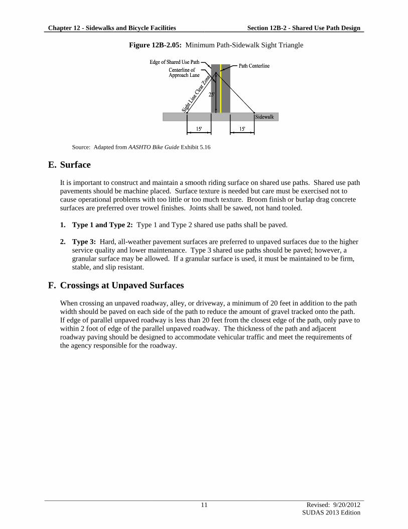
Chapter 12 - Sidewalks and Bicycle Facilities Section 12B-2 - Shared Use Path Design
11 Revised: 9/20/2012
SUDAS 2013 Edition
Figure 12B-2.05: Minimum Path-Sidewalk Sight Triangle
Source: Adapted from AASHTO Bike Guide Exhibit 5.16
E. Surface
It is important to construct and maintain a smooth riding surface on shared use paths. Shared use path
pavements should be machine placed. Surface texture is needed but care must be exercised not to
cause operational problems with too little or too much texture. Broom finish or burlap drag concrete
surfaces are preferred over trowel finishes. Joints shall be sawed, not hand tooled.
1. Type 1 and Type 2: Type 1 and Type 2 shared use paths shall be paved.
2. Type 3: Hard, all-weather pavement surfaces are preferred to unpaved surfaces due to the higher
service quality and lower maintenance. Type 3 shared use paths should be paved; however, a
granular surface may be allowed. If a granular surface is used, it must be maintained to be firm,
stable, and slip resistant.
F. Crossings at Unpaved Surfaces
When crossing an unpaved roadway, alley, or driveway, a minimum of 20 feet in addition to the path
width should be paved on each side of the path to reduce the amount of gravel tracked onto the path.
If edge of parallel unpaved roadway is less than 20 feet from the closest edge of the path, only pave to
within 2 foot of edge of the parallel unpaved roadway. The thickness of the path and adjacent
roadway paving should be designed to accommodate vehicular traffic and meet the requirements of
the agency responsible for the roadway.
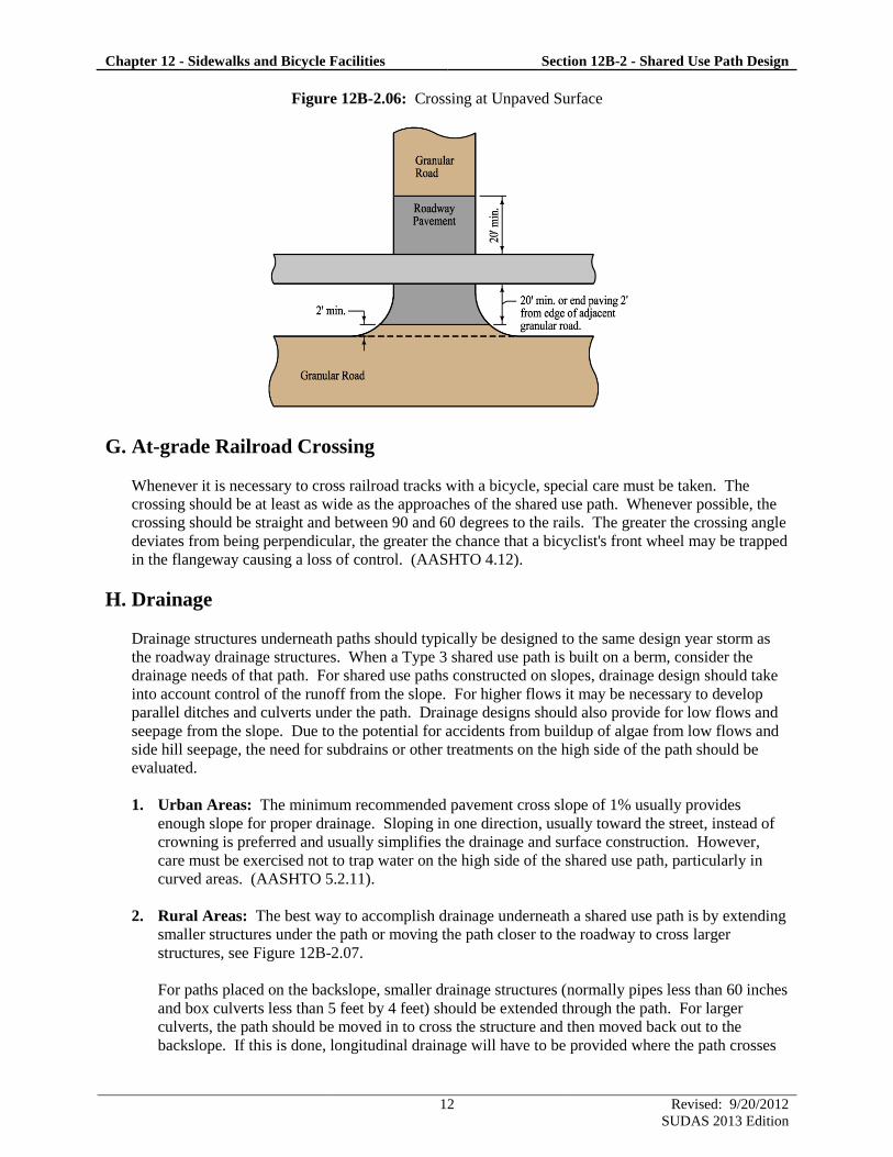
Chapter 12 - Sidewalks and Bicycle Facilities Section 12B-2 - Shared Use Path Design
12 Revised: 9/20/2012
SUDAS 2013 Edition
Figure 12B-2.06: Crossing at Unpaved Surface
G. At-grade Railroad Crossing
Whenever it is necessary to cross railroad tracks with a bicycle, special care must be taken. The
crossing should be at least as wide as the approaches of the shared use path. Whenever possible, the
crossing should be straight and between 90 and 60 degrees to the rails. The greater the crossing angle
deviates from being perpendicular, the greater the chance that a bicyclist's front wheel may be trapped
in the flangeway causing a loss of control. (AASHTO 4.12).
H. Drainage
Drainage structures underneath paths should typically be designed to the same design year storm as
the roadway drainage structures. When a Type 3 shared use path is built on a berm, consider the
drainage needs of that path. For shared use paths constructed on slopes, drainage design should take
into account control of the runoff from the slope. For higher flows it may be necessary to develop
parallel ditches and culverts under the path. Drainage designs should also provide for low flows and
seepage from the slope. Due to the potential for accidents from buildup of algae from low flows and
side hill seepage, the need for subdrains or other treatments on the high side of the path should be
evaluated.
1. Urban Areas: The minimum recommended pavement cross slope of 1% usually provides
enough slope for proper drainage. Sloping in one direction, usually toward the street, instead of
crowning is preferred and usually simplifies the drainage and surface construction. However,
care must be exercised not to trap water on the high side of the shared use path, particularly in
curved areas. (AASHTO 5.2.11).
2. Rural Areas: The best way to accomplish drainage underneath a shared use path is by extending
smaller structures under the path or moving the path closer to the roadway to cross larger
structures, see Figure 12B-2.07.
For paths placed on the backslope, smaller drainage structures (normally pipes less than 60 inches
and box culverts less than 5 feet by 4 feet) should be extended through the path. For larger
culverts, the path should be moved in to cross the structure and then moved back out to the
backslope. If this is done, longitudinal drainage will have to be provided where the path crosses
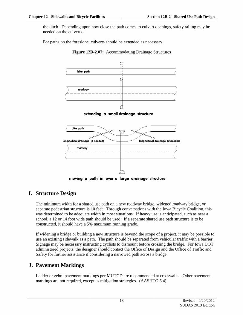
Chapter 12 - Sidewalks and Bicycle Facilities Section 12B-2 - Shared Use Path Design
13 Revised: 9/20/2012
SUDAS 2013 Edition
the ditch. Depending upon how close the path comes to culvert openings, safety railing may be
needed on the culverts.
For paths on the foreslope, culverts should be extended as necessary.
Figure 12B-2.07: Accommodating Drainage Structures
I. Structure Design
The minimum width for a shared use path on a new roadway bridge, widened roadway bridge, or
separate pedestrian structure is 10 feet. Through conversations with the Iowa Bicycle Coalition, this
was determined to be adequate width in most situations. If heavy use is anticipated, such as near a
school, a 12 or 14 foot wide path should be used. If a separate shared use path structure is to be
constructed, it should have a 5% maximum running grade.
If widening a bridge or building a new structure is beyond the scope of a project, it may be possible to
use an existing sidewalk as a path. The path should be separated from vehicular traffic with a barrier.
Signage may be necessary instructing cyclists to dismount before crossing the bridge. For Iowa DOT
administered projects, the designer should contact the Office of Design and the Office of Traffic and
Safety for further assistance if considering a narrowed path across a bridge.
J. Pavement Markings
Ladder or zebra pavement markings per MUTCD are recommended at crosswalks. Other pavement
markings are not required, except as mitigation strategies. (AASHTO 5.4).
Chapter 12 - Sidewalks and Bicycle Facilities Section 12B-2 - Shared Use Path Design
14 Revised: 9/20/2012
SUDAS 2013 Edition
K. Signing
All signs should be retroreflective and conform to the color, legend, and shape requirements
described in the MUTCD. In addition, guide signing, such as to indicate directions, destinations,
distances, route numbers, and names of crossing streets should be used. In general, uniform
application of traffic control devices, as described in the MUTCD, should be used and will tend to
encourage proper bicyclist behavior. (AASHTO 5.4).
L. Lighting
Fixed-source lighting reduces conflicts along shared use paths and at intersections. In addition,
lighting allows the bicyclist to see the shared use path direction, surface conditions, and obstacles.
Lighting for paths is important and may be considered where heavy nighttime riding is expected (e.g.,
paths serving college students or commuters) and at roadway intersections. Lighting should be
considered through underpasses or tunnels and when nighttime security could be a problem. Where
special security problems exist, higher illumination levels may be considered. Light standards (poles)
should meet the recommended horizontal and vertical clearances. (AASHTO 5.2.12).
12B-3
Design Manual
Chapter 12 - Sidewalks and Bicycle Facilities
12B - Bicycle Facilities
1 Revised: 2013 Edition
On-Street Bicycle Facilities
A. General
Cyclists have similar access and mobility needs as other transportation users. However, cyclists must
use their own strength and energy to propel the bicycle, thus a bicyclist is generally slower than other
vehicles that are operating on the roadway. Additionally, cyclists are more vulnerable to injury
during a crash and are of any age group. With these factors in mind, it is imperative that designing
bicycle facilities is done with great care.
The 2012 draft of the “AASHTO Guide for the Development of Bicycle Facilities” (or AASHTO Bike
Guide) was used as a reference for developing this section. References made to the AASHTO Bike
Guide within this section are shown in parentheses, e.g. (AASHTO 4.2).
B. Elements of Design
Since cyclists usually have a higher eye height and are slower than the adjacent traffic, the roadway
design elements for motor vehicles usually meet or exceed the minimum design elements required for
cyclists.
Surface conditions affect cyclists more significantly than motor vehicles. Therefore, when
establishing bicycle lanes and routes, it is important that the roadway surface is in good condition and
is free of potholes, bumps, cracks, loose gravel, etc. If the roadway is not in good bicycle riding
condition, it should be repaired either with resurfacing or reconstruction. Chip-sealed surfaces prove
to create difficult riding conditions. (AASHTO 4.2).
C. Facilities
Except where prohibited, bicycles may be operated on all roadways. The following are the different
types of bicycle facilities that are located on the roadway along with their design criteria.
1. Shared Lanes: Shared lanes already exist on local neighborhoods and city streets. However,
these lanes can include design features that will make the lanes more bicycle friendly. This
includes good pavement quality, adequate sight distance, lower speeds, bicycle-compatible
drainage grates, bridge expansion joints, railroad crossings, etc. (AASHTO 4.3).
a. Major Roads (Wide Curb/Outside Lanes): Lane widths should be 13 to 15 feet wide with
14 foot lanes as preferred. Lane widths of 14 feet and greater allow motorists to pass cyclists
without encroaching into adjacent lanes; however, it is important to note that 15 foot lanes
should be used only on appropriate sections with steep grades or sections where drainage
grates, raised delineators, or on-street parking effectively reduces the usable width. The
gutter should not be included in the measurement as usable width. Lanes 15 feet or wider
could encourage faster vehicular movements or even two vehicles operating side by side in
one lane. (AASHTO 4.3.1).
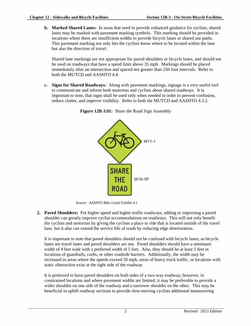
Chapter 12 - Sidewalks and Bicycle Facilities Section 12B-3 - On-Street Bicycle Facilities
2 Revised: 2013 Edition
b. Marked Shared Lanes: In areas that need to provide enhanced guidance for cyclists, shared
lanes may be marked with pavement marking symbols. This marking should be provided in
locations where there are insufficient widths to provide bicycle lanes or shared use paths.
This pavement marking not only lets the cyclists know where to be located within the lane
but also the direction of travel.
Shared lane markings are not appropriate for paved shoulders or bicycle lanes, and should not
be used on roadways that have a speed limit above 35 mph. Markings should be placed
immediately after an intersection and spaced not greater than 250 foot intervals. Refer to
both the MUTCD and AASHTO 4.4.
c. Signs for Shared Roadways: Along with pavement markings, signage is a very useful tool
to communicate and inform both motorists and cyclists about shared roadways. It is
important to note, that signs shall be used only when needed in order to prevent confusion,
reduce clutter, and improve visibility. Refer to both the MUTCD and AASHTO 4.3.2.
Figure 12B-3.01: Share the Road Sign Assembly
Source: AASHTO Bike Guide Exhibit 4.1
2. Paved Shoulders: For higher speed and higher traffic roadways, adding or improving a paved
shoulder can greatly improve cyclist accommodations on roadways. This will not only benefit
the cyclists and motorists by giving the cyclists a place to ride that is located outside of the travel
lane, but it also can extend the service life of roads by reducing edge deterioration.
It is important to note that paved shoulders should not be confused with bicycle lanes, as bicycle
lanes are travel lanes and paved shoulders are not. Paved shoulders should have a minimum
width of 4 feet wide with a preferred width of 5 feet. Also, they should be at least 5 feet in
locations of guardrails, curbs, or other roadside barriers. Additionally, the width may be
increased in areas where the speeds exceed 50 mph, areas of heavy truck traffic, or locations with
static obstruction exist at the right side of the roadway.
It is preferred to have paved shoulders on both sides of a two-way roadway; however, in
constrained locations and where pavement widths are limited, it may be preferable to provide a
wider shoulder on one side of the roadway and a narrower shoulder on the other. This may be
beneficial in uphill roadway sections to provide slow-moving cyclists additional maneuvering
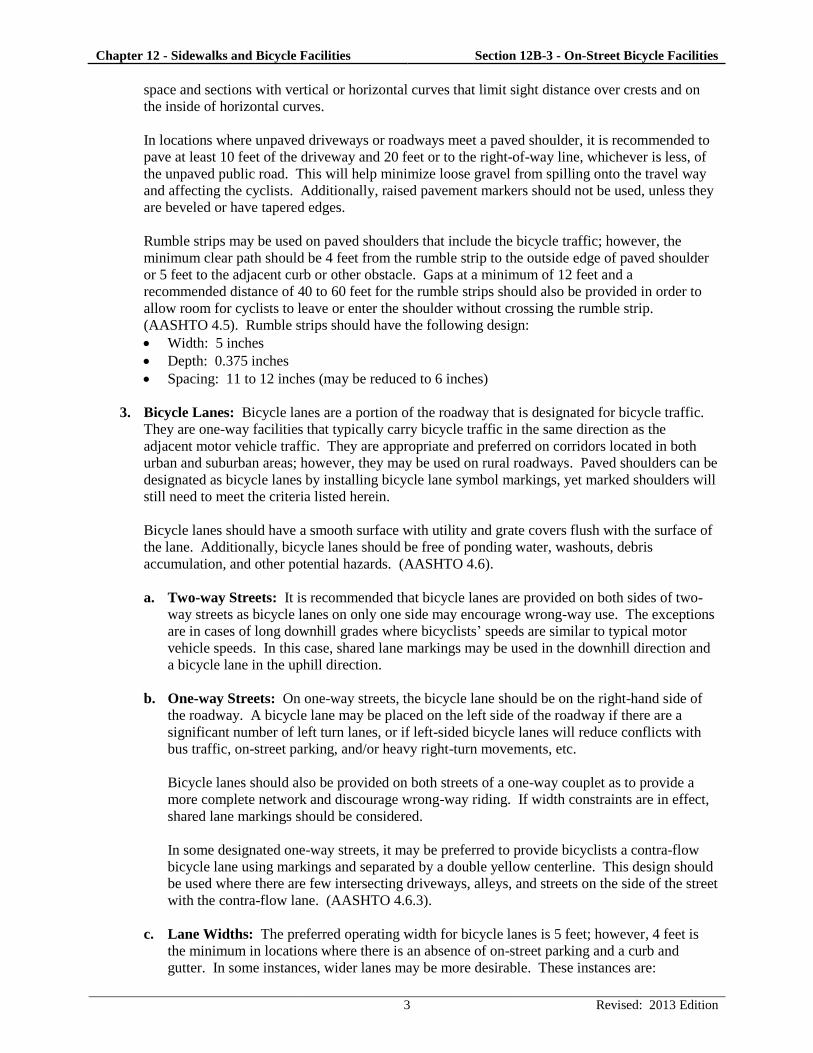
Chapter 12 - Sidewalks and Bicycle Facilities Section 12B-3 - On-Street Bicycle Facilities
3 Revised: 2013 Edition
space and sections with vertical or horizontal curves that limit sight distance over crests and on
the inside of horizontal curves.
In locations where unpaved driveways or roadways meet a paved shoulder, it is recommended to
pave at least 10 feet of the driveway and 20 feet or to the right-of-way line, whichever is less, of
the unpaved public road. This will help minimize loose gravel from spilling onto the travel way
and affecting the cyclists. Additionally, raised pavement markers should not be used, unless they
are beveled or have tapered edges.
Rumble strips may be used on paved shoulders that include the bicycle traffic; however, the
minimum clear path should be 4 feet from the rumble strip to the outside edge of paved shoulder
or 5 feet to the adjacent curb or other obstacle. Gaps at a minimum of 12 feet and a
recommended distance of 40 to 60 feet for the rumble strips should also be provided in order to
allow room for cyclists to leave or enter the shoulder without crossing the rumble strip.
(AASHTO 4.5). Rumble strips should have the following design:
Width: 5 inches
Depth: 0.375 inches
Spacing: 11 to 12 inches (may be reduced to 6 inches)
3. Bicycle Lanes: Bicycle lanes are a portion of the roadway that is designated for bicycle traffic.
They are one-way facilities that typically carry bicycle traffic in the same direction as the
adjacent motor vehicle traffic. They are appropriate and preferred on corridors located in both
urban and suburban areas; however, they may be used on rural roadways. Paved shoulders can be
designated as bicycle lanes by installing bicycle lane symbol markings, yet marked shoulders will
still need to meet the criteria listed herein.
Bicycle lanes should have a smooth surface with utility and grate covers flush with the surface of
the lane. Additionally, bicycle lanes should be free of ponding water, washouts, debris
accumulation, and other potential hazards. (AASHTO 4.6).
a. Two-way Streets: It is recommended that bicycle lanes are provided on both sides of two-
way streets as bicycle lanes on only one side may encourage wrong-way use. The exceptions
are in cases of long downhill grades where bicyclists’ speeds are similar to typical motor
vehicle speeds. In this case, shared lane markings may be used in the downhill direction and
a bicycle lane in the uphill direction.
b. One-way Streets: On one-way streets, the bicycle lane should be on the right-hand side of
the roadway. A bicycle lane may be placed on the left side of the roadway if there are a
significant number of left turn lanes, or if left-sided bicycle lanes will reduce conflicts with
bus traffic, on-street parking, and/or heavy right-turn movements, etc.
Bicycle lanes should also be provided on both streets of a one-way couplet as to provide a
more complete network and discourage wrong-way riding. If width constraints are in effect,
shared lane markings should be considered.
In some designated one-way streets, it may be preferred to provide bicyclists a contra-flow
bicycle lane using markings and separated by a double yellow centerline. This design should
be used where there are few intersecting driveways, alleys, and streets on the side of the street
with the contra-flow lane. (AASHTO 4.6.3).
c. Lane Widths: The preferred operating width for bicycle lanes is 5 feet; however, 4 feet is
the minimum in locations where there is an absence of on-street parking and a curb and
gutter. In some instances, wider lanes may be more desirable. These instances are:
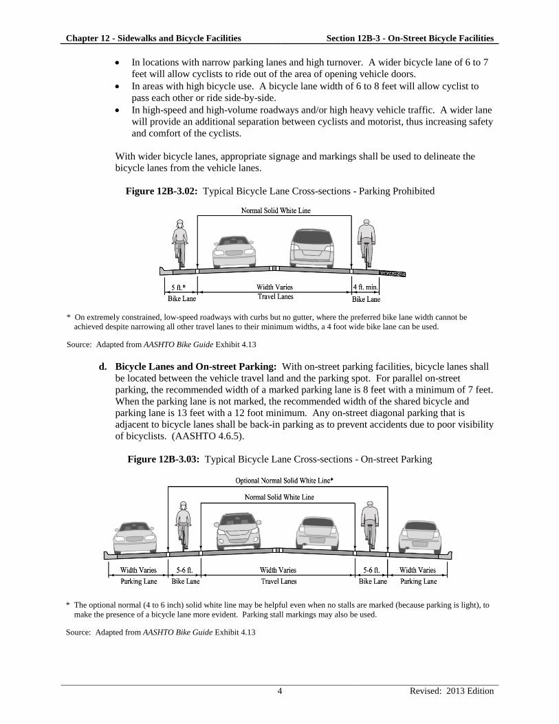
Chapter 12 - Sidewalks and Bicycle Facilities Section 12B-3 - On-Street Bicycle Facilities
4 Revised: 2013 Edition
In locations with narrow parking lanes and high turnover. A wider bicycle lane of 6 to 7
feet will allow cyclists to ride out of the area of opening vehicle doors.
In areas with high bicycle use. A bicycle lane width of 6 to 8 feet will allow cyclist to
pass each other or ride side-by-side.
In high-speed and high-volume roadways and/or high heavy vehicle traffic. A wider lane
will provide an additional separation between cyclists and motorist, thus increasing safety
and comfort of the cyclists.
With wider bicycle lanes, appropriate signage and markings shall be used to delineate the
bicycle lanes from the vehicle lanes.
Figure 12B-3.02: Typical Bicycle Lane Cross-sections - Parking Prohibited
* On extremely constrained, low-speed roadways with curbs but no gutter, where the preferred bike lane width cannot be
achieved despite narrowing all other travel lanes to their minimum widths, a 4 foot wide bike lane can be used.
Source: Adapted from AASHTO Bike Guide Exhibit 4.13
d. Bicycle Lanes and On-street Parking: With on-street parking facilities, bicycle lanes shall
be located between the vehicle travel land and the parking spot. For parallel on-street
parking, the recommended width of a marked parking lane is 8 feet with a minimum of 7 feet.
When the parking lane is not marked, the recommended width of the shared bicycle and
parking lane is 13 feet with a 12 foot minimum. Any on-street diagonal parking that is
adjacent to bicycle lanes shall be back-in parking as to prevent accidents due to poor visibility
of bicyclists. (AASHTO 4.6.5).
Figure 12B-3.03: Typical Bicycle Lane Cross-sections - On-street Parking
* The optional normal (4 to 6 inch) solid white line may be helpful even when no stalls are marked (because parking is light), to
make the presence of a bicycle lane more evident. Parking stall markings may also be used.
Source: Adapted from AASHTO Bike Guide Exhibit 4.13
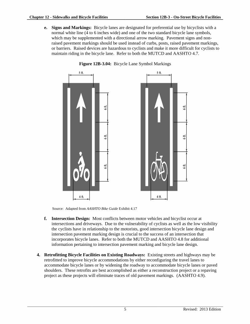
Chapter 12 - Sidewalks and Bicycle Facilities Section 12B-3 - On-Street Bicycle Facilities
5 Revised: 2013 Edition
e. Signs and Markings: Bicycle lanes are designated for preferential use by bicyclists with a
normal white line (4 to 6 inches wide) and one of the two standard bicycle lane symbols,
which may be supplemented with a directional arrow marking. Pavement signs and non-
raised pavement markings should be used instead of curbs, posts, raised pavement markings,
or barriers. Raised devices are hazardous to cyclists and make it more difficult for cyclists to
maintain riding in the bicycle lane. Refer to both the MUTCD and AASHTO 4.7.
Figure 12B-3.04: Bicycle Lane Symbol Markings
Source: Adapted from AASHTO Bike Guide Exhibit 4.17
f. Intersection Design: Most conflicts between motor vehicles and bicyclist occur at
intersections and driveways. Due to the vulnerability of cyclists as well as the low visibility
the cyclists have in relationship to the motorists, good intersection bicycle lane design and
intersection pavement marking design is crucial to the success of an intersection that
incorporates bicycle lanes. Refer to both the MUTCD and AASHTO 4.8 for additional
information pertaining to intersection pavement marking and bicycle lane design.
4. Retrofitting Bicycle Facilities on Existing Roadways: Existing streets and highways may be
retrofitted to improve bicycle accommodations by either reconfiguring the travel lanes to
accommodate bicycle lanes or by widening the roadway to accommodate bicycle lanes or paved
shoulders. These retrofits are best accomplished as either a reconstruction project or a repaving
project as these projects will eliminate traces of old pavement markings. (AASHTO 4.9).
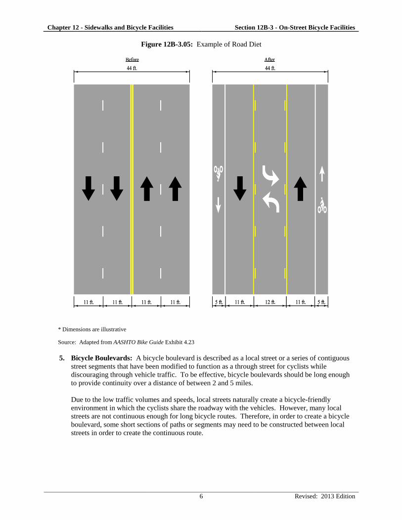
Chapter 12 - Sidewalks and Bicycle Facilities Section 12B-3 - On-Street Bicycle Facilities
6 Revised: 2013 Edition
Figure 12B-3.05: Example of Road Diet
* Dimensions are illustrative
Source: Adapted from AASHTO Bike Guide Exhibit 4.23
5. Bicycle Boulevards: A bicycle boulevard is described as a local street or a series of contiguous
street segments that have been modified to function as a through street for cyclists while
discouraging through vehicle traffic. To be effective, bicycle boulevards should be long enough
to provide continuity over a distance of between 2 and 5 miles.
Due to the low traffic volumes and speeds, local streets naturally create a bicycle-friendly
environment in which the cyclists share the roadway with the vehicles. However, many local
streets are not continuous enough for long bicycle routes. Therefore, in order to create a bicycle
boulevard, some short sections of paths or segments may need to be constructed between local
streets in order to create the continuous route.
Chapter 12 - Sidewalks and Bicycle Facilities Section 12B-3 - On-Street Bicycle Facilities
7 Revised: 2013 Edition
Some design elements that are involved in the design of bicycle boulevards are:
Traffic diverters at key intersections that allow bicycle through traffic but reduce or deny
vehicle traffic
Two-way stop-controlled intersection that give the bicycle boulevard priority
Neighborhood traffic circles or mini-roundabouts
Traffic-calming features
Wayfinding signs to guide bicyclists
Shared lane markings where appropriate
Bicycle-sensitive traffic signals at busy intersections
Median refuges large enough for bicycles
Curb extensions on crossed thoroughfare with on-street parking
It is important to note that before the design of a bicycle boulevards, an investigation of the
proposed boulevards should be performed since many of the design elements listed may already
be in use. (AASHTO 4.10).
D. Bicycle Guide Signs
Guide signs are an important element to all bicycle facilities as they help cyclists navigate to their
destination. There are many guidelines and standards that go along with the type and placement of
guide signs. See both the MUTCD and AASHTO 4.11.
E. Railroad Crossings for Bicycles
Where roadways or shared use paths cross railroad tracks on a diagonal, the designer should take care
in the design of the crossing as to prevent steering difficulties for the cyclists. This includes:
Increasing the skew angle between the tracks and the bike path to 60 degrees or greater so
bicyclists can avoid catching their wheels in the flange of the tracks. This can be accomplished
with reverse curves or with a widened shoulder.
Creating a smooth crossing surface that will last over time and not be slippery when wet.
Minimizing flange openings as much as possible. Under special rail conditions, rubber fillers
products may be used. Contact the railroad company for approval prior to the design and
installation of the fillers.
See both the MUTCD and AASHTO 4.12.1.
F. Obstruction Markings for Bicycle Lanes
The design of bicycle facilities should avoid obstruction and barriers as much as possible. However,
in rare circumstance in which an obstruction or barrier cannot be avoided, signs, reflectors, and
markings should be utilized to alert they cyclists. (AASHTO 4.12.2).
G. Traffic Signals for Bicycles
Traffic signals have traditionally been designed based off the operating characteristics of motor
vehicles. However, at intersections with medium to high bicycle usage that incorporates shared lanes
or bicycle lanes, traffic signal designers should include the characteristics of bicyclists to their traffic
signals. The signal parameters that could be modified to accommodate bicyclists when appropriate
are minimum green interval, all-red interval, and extension time. This information can be found in
AASHTO 4.12.3 and 4.12.4 as well as the latest edition of the “Highway Capacity Manual.”
Chapter 12 - Sidewalks and Bicycle Facilities Section 12B-3 - On-Street Bicycle Facilities
8 Revised: 2013 Edition
H. Bridges and Viaducts for Bicycles
Two considerations should be taken into account before the design of bicycle accommodations with
bridges - the length of the bridge and the design of the approach roadway. If the bridge approach
does not include bicycle accommodations, the bridge can still facilitate use by bicyclists by including
a wide shoulder or bicycle lanes and include paved shoulder, shared lanes, or shared use path as part
of the bridge project. Additionally, if the bridge is continuous and spans over a 1/2 mile in length
with speed of excess of 45 mph, a concrete barrier separated shared use path on both sides of the
bridge should be considered. By allowing paths on both sides of the bridge, wrong-way travel of the
cyclists will be deterred. (AASHTO 4.12.5).
I. Traffic Calming and Management of Bicycles
There are many things that a designer can do to reduce the traffic speed of cyclists and to manage
bicycles effectively. These things include narrowing streets to create a sense of enclosure; adding
vertical deflections such as speed humps, speed tables, speed cushions, and raised sidewalks; adding
curb extension or chokers; adding chicanes; installing traffic circles; and incorporating multi-way
stops. (AASHTO 4.12.6 and 4.12.7).
J. Intake Grates and Manhole Castings for Bicycle Travel
It is important to have intake grate openings run perpendicular to the direction of travel as this will
prevent bicycle wheels from dropping into the gaps and causing crashes. SUDAS Specifications
Figure/Iowa DOT Standard Road Plan SW-603, Type R and Type S, are intake grates that are
appropriate for use on bicycle routes. Where it is not immediately feasible to replace existing grates,
metal straps can be welded across slots perpendicular to the direction of travel at a maximum
longitudinal spacing of 4 inches. Additionally, open-throat intakes can be used instead of grate
intakes in order to eliminate the grate all together. The presence of the depressed throat of the intake
should be taken into account.
Surface grates and manhole castings should be flush with the roadway surface. In the case of
overlays, the grates and castings should be raised to within 1/4 inch of the new surface. If this is not
possible or practical, the pavement must taper into drainage inlets so it does not have an abrupt edge
at the inlet. Take care in the design of the taper of the pavement around inlets and castings so to
avoid “birdbaths” or low spots that are not drainable in the pavement. (AASHTO 4.12.8).
K. Bicycles at Interchanges
When designing bicycle facilities at interchanges, it is important to consider both safety and
convenience for the cyclists. This is best achieved by designing right-angle intersection or single lane
roundabouts at the intersection between the local route and the ramps. These designs promote low
speeds, minimize conflict areas, and increase visibility. Additionally, stop signs or signals are
encouraged for motorists turning from the off ramp to the local route rather than allowing a free-
flowing movement as this will increase the safety of the cyclists.
At complex interchanges that include high-speeds and free-flowing motor vehicle movements, a well
signed and clearly directed grade-separated crossings may be necessary. These grade-separated
facilities should still include good visibility, be convenient, and consist of adequate lighting.
(AASHTO 4.12.9).
Chapter 12 - Sidewalks and Bicycle Facilities Section 12B-3 - On-Street Bicycle Facilities
9 Revised: 2013 Edition
L. Bicycles at Roundabouts
In designing roundabouts for bicycle usage, single lane roundabouts are safer and easier to navigate
for cyclists. Multi-lane roundabouts include too many conflict points due to bicycle
weaving/changing lanes and motorist cutting off cyclists when exiting the roundabout.
In instances of bicycle lanes approaching a roundabout, the bicycle lane should be terminated at least
100 feet from the edge of the entry curve of the roundabout and prior to the crosswalk. Also, prior to
the roundabout and after the termination of the bicycle lane, a tapering of the bicycle lane to the travel
lane should be provided. This is done to achieve the appropriate entry width for the roundabout and
the taper should be 7:1 for a 20 mph design speed or 40 feet for a 5 to 6 foot bicycle lane.
Additionally, the bicycle lane line should be dotted 50 to 200 feet in advance of the taper to
encourage cyclists to merge into traffic.
In rare circumstances, bicyclists should be given the option to merge with traffic prior to the
roundabout or exit onto the adjacent sidewalk via a ramp. These instances include multi-lane
roundabouts, high design speed roundabouts, and/or complex roundabouts. However, in some
jurisdictions, cyclists riding on sidewalks may be prohibited. In designing bicycle ramps prior to a
roundabout, the following criteria should be followed:
Place bicycle ramps at the end of the full width bicycle lane and just before the taper of the
bicycle lane.
Where no bicycle lane is present on the approach to the roundabout, a bicycle ramp should be
placed at least 50 feet prior to the crosswalk at the roundabout.
Bicycle ramps should be placed at a 35 to 45 degree angle to the roadway.
If the ramp is placed outside of the sidewalk, it can have up to a 20% slope; if the ramp is placed
within the sidewalk, it should be designed in a manner to prevent a tripping hazard.
If the ramp is placed outside the sidewalk, a detectable warning device should be placed at the top
of the ramp; if the ramp is placed within the sidewalk, the detectable warning device should be
placed at the bottom of the ramp.
Bike ramps should be placed relatively far from the marked crosswalk as to prevent pedestrians
from mistaking the ramp as a crosswalk.
Bike ramps at the exits of roundabouts should be built with the similar geometry and placement as the
ramps that are designed at roundabout entries. Bike ramps at the exits of roundabouts should be
placed at least 50 feet beyond the crosswalk of the roundabout. Refer to AASHTO 4.12.10 and the
FHWA Roundabout Guide.


