JD0064-00
JD0064-00.Rev2.doc Rev. 2 - Last Printed 5/4/2017 10:40:00 AM
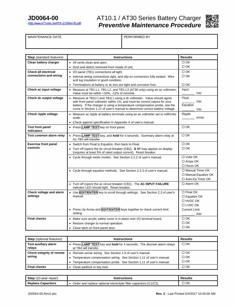
AT10.1 / AT30 Series Battery Charger (http://www.ATSeries.net/PDFs/JD0064-00.pdf) Preventive Maintenance Procedure
MAINTENANCE DATE
PERFORMED BY
Step (standard features) Instructions Results
Clean battery charger All vents clean and open.
Dust and debris removed from inside of unit.
OK
OK
Check all electrical connections and wiring
I/O panel (TB1) connections all tight.
Internal wiring connections tight, and slip-on connectors fully seated. Wire and lug insulation in good condition.
Terminations at battery or dc bus are tight and corrosion free.
OK
OK
OK
Check ac input voltage Measure at TB1-L1, TB1-L2, and TB1-L3 (AT30 only) using an ac voltmeter. Value must be within +10%, -12% of nominal.
Input Vac
Check dc output voltage Measure at TB1(+) and TB1(-) using a dc voltmeter. Value should agree with front panel voltmeter within 1%, and must be correct values for your battery. If the charger is using a temperature compensation probe, see the curve in Section 1.11 of user's manual to determine correct battery voltage.
Float Vdc Equalize
Vdc
Check ripple voltage Measure ac ripple at battery terminals using an ac voltmeter set to milliVolts scale.
Check against specification in Appendix A of user's manual.
Ripple mVac
Test front panel indicators
Press LAMP TEST key on front panel. OK
Test common alarm relay Press LAMP TEST key, and hold for 4 seconds. Summary alarm relay at A1-TB3 will transfer.
OK
Exercise front panel controls
Switch from Float to Equalize, then back to Float.
Turn off (open) the dc circuit breaker (CB2). E 07 may appear on display (requires at least 5% of rated output current). Reset breaker.
OK
OK
Cycle through meter modes. See Section 2.2.2 of user's manual. Volts OK
Amps OK
Hours OK
Cycle through equalize methods. See Section 2.2.3 of user's manual. Manual Timer OK
Manual Equalize OK
Auto-Eq Timer OK
Turn off (open) the ac circuit breaker (CB1). The AC INPUT FAILURE indicator LED should light. Reset breaker.
Alarm OK
Check voltage and alarm settings
Use EDIT/ENTER key to scroll through settings. See Section 2.3 of user's manual.
Press Up Arrow and EDIT/ENTER keys together to check current limit setting
Float OK
Equalize OK
HVDC OK
LVDC OK
Current Limit
Adc
Final checks Make sure acrylic safety cover is in place over I/O terminal board.
Restore charger to normal operation.
Close latch on front panel door.
OK
OK
OK
Step (optional features) Instructions Results
Test auxiliary alarm relays
Press LAMP TEST key and hold for 4 seconds. The discreet alarm relays at TB4 will transfer.
OK
Check integrity of remote wiring
Remote sense wiring. See Section 1.9 of user's manual.
Temperature compensation wiring. See Section 1.11 of user's manual.
Temperature compensation probe. See Section 1.11 of user's manual.
OK
OK
OK
Final checks Close padlock or key lock. OK
Step (10-year repair) Instructions Results
Replace Capacitors Order and replace optional electrolytic filter capacitors (C1/C2). OK


