7/17/2019 An innovative design method for compliant mechanisms combining structural optimisations and designer creativity..pdf
http://slidepdf.com/reader/full/an-innovative-design-method-for-compliant-mechanisms-combining-structural-optimisations 1/31
Journal of Engineering Design
Vol. 20, No. 2, April 2009, 125–154
An innovative design method for compliant mechanisms
combining structural optimisations and designer creativity
Masakazu Kobayashia*, Shinji Nishiwakib, Kazuhiro Izuib and Masataka Yoshimurab
a Department of Information-aided Technology, Toyota Technological Institute, Nagoya City, Japan;b Department of Aeronautics and Astronautics, Kyoto University, Kyoto City, Japan
( Received 9 February 2007; final version received 11 July 2007 )
This paper proposes an innovative, integrated design method for the design of practical and sophisticatedcompliant mechanisms. The approach consists of two optimisation methods, topology and shape optimi-sation, plus a scheme to implement designer input of ideas. In the first step, a designer explores the mostfruitful design concepts for mechanisms that achieve the design specifications, by combining compliantmechanisms created by the topology optimisation with additional mechanisms prepared by the designer.In this first step, a support method based on the visualisation of the designer’s thinking processes assiststhe designer in his or her exploration of new ideas and design concepts. In the second step, the shapeoptimisation yields a detailed optimal shape based on the design concept. The combination of compliantmechanisms with the additional mechanisms enables the creation of devices having increased capabilityor higher performance than would be possible using a single compliant mechanism designed by topol-
ogy optimisation alone. Executing the shape optimisation after initial design concepts have been exploredfacilitates the determination of a detailed optimal shape, and also enables to consider non-linear analy-sis and stress concentration and to make accurate quantitative performance evaluations, which topologyoptimisation cannot provide.
Keywords: optimal design; compliant mechanism; topology optimisation; shape optimisation; designercreativity; creative support system
1. Introduction
In mechanical design, mechanisms consisting of rigid parts linked to moveable joints are oftenused, and in such mechanisms the relative motion of the links is constrained by the joints. Onthe other hand, compliant mechanisms (Howell 2001) utilise a structure’s flexibility to achieve aspecified motion, by deforming the structure elastically, instead of relying on joint movements.Such compliant mechanisms often consist of fewer parts than rigid-link mechanisms, or caneven be monolithic, and, compared with rigid-link mechanisms, have several merits (Howell2001, Ananthasuresh and Kota 1995), such as reduced wear and operation noise, zero backlash,
*Corresponding author. Email: [email protected]
ISSN 0954-4828 print/ISSN 1466-1837 online
7/17/2019 An innovative design method for compliant mechanisms combining structural optimisations and designer creativity..pdf
http://slidepdf.com/reader/full/an-innovative-design-method-for-compliant-mechanisms-combining-structural-optimisations 2/31
126 M. Kobayashi et al.
freedom from lubrication requirements, weight savings, manufacturing advantages, and ease of miniaturisation. Therefore, the use of compliant mechanisms in mechanical products, medicalinstruments and micro-electro mechanical systems (Howell 2001, Larsen et al. 1997) can beexpected to increase.
For such promising compliant mechanisms, many design methods have been developed overthe past few decades, and these canbe classified into the following two types. The first method typeis based on kinematics, where the designer creates a traditional rigid-link mechanism consistingof rigid parts and joints, and then creates a compliant mechanism by converting the joints toflexural parts. Her and Midah (1987) proposed a methodology for obtaining all possible compliantmechanisms from a given rigid body kinematic chain. Howell and Midah (1994) proposed ananalysis and synthesis method using a pseudo-rigid-body model. The advantage of a kinematicsapproach is that the designer can utilise an already well-developed body of knowledge concerningkinematics and rigid-link mechanisms. However, such methods require trial and error processeson the part of the designer, to find the best conversion, and the best traditional mechanism does
not always result in the best compliant mechanism.The second method type is based on topology optimisation (Bendsøe and Kikuchi 1988), where
the designer configures the design domain, boundary conditions and the location and directionof the input and output forces of the target mechanism, and then the topology optimisation isconducted to calculate an optimal shape under these conditions. Sigmund (1997) proposed adesign approach using topology optimisation based on the densitymethod, and Larsen et al. (1996)also proposed a similar design approach. On the other hand, the approach proposed by Nishiwakiet al. (2001) was based on the homogenisation design method. The advantage of a topologyoptimisation-based approach is that knowledge of kinematics is not required and fully optimalconfigurations can be yielded without the designer’s trial and error processes.
Topology optimisation, however, has several inherent problems, such as numerical problemsthat typically result in checkerboards or hinge patterns – numerical difficulties in utilising localphysical quantities, such as stress and displacement during the optimisation process. Topologyoptimisation can also not easily consider large deformations and non-linear analysis, or makedetailed shape decisions,although numerous methods have beendeveloped in an attempt to resolvethese challenges. For the checkerboard pattern problem, methods based on filtering techniques(Sigmund and Petersson 1998, Fujii and Kikuchi 2000, Bourdin 2001) are often used, but suchmethods merely address the symptoms rather than the core difficulty. On the other hand, severalmethods that resolve this problem theoretically have been proposed, such as node-based topologyoptimisation (Matsui and Terada 2004). The appearance of hinges is another numerical obstacle,an outcome of flexibility maximisation when topology optimisation is used for the design of a structure having flexible regions. Hinges must be avoided due to manufacturing infeasibility.To eliminate hinges, Poulsen (2003) proposed a method based on member size control, andYoon et al. (2004) proposed a method using wavelets. To employ local physical quantities, severalmethods (Pereira et al. 2004, Duysinx and Bendsøe 1998) tried various ways of considering stressconstraints, but the direct implementation of stress constraints in compliant mechanism designremains problematic at the present time. To precisely assess the quantitative performance of acompliant mechanism during the optimisation process, non-linear and large deformation analysisisdesirable.Pedersenet al. (2001)and Bruns andTortorelli (2001)proposed topology optimisationmethods that include large deformation analysis, but these methods have unwieldy computationalrequirement, and local solutions with physically meaningless shapes may be presented as optimal
results. Furthermore, there is little difference in the optimal results generated by these methodsthat consider large deformations, and those obtained by methods that do not, if we do not explicitlyd l ith hi hl li ff t h b kli h
7/17/2019 An innovative design method for compliant mechanisms combining structural optimisations and designer creativity..pdf
http://slidepdf.com/reader/full/an-innovative-design-method-for-compliant-mechanisms-combining-structural-optimisations 3/31
Journal of Engineering Design 127
deformation paths. To enable the design of such compliant mechanisms, having increasinglysophisticated functions, a number of design methods have been developed, based on kinematicsand topology optimisation approaches. In the kinematics approach, Midha et al. (2004) proposeda method based on pseudo-rigid-body models and rigid-body mechanism synthesis for function,
path and motion generation. Jensen and Howell (2004) considered several mechanism configura-tions involving slider joints, and facilitated the design of bi-stable compliant mechanisms usingdesigners’ prior knowledge of compliant mechanism configurations. Crane et al. (2004) designeda floating-opposing-arm centrifugal clutch using a pseudo-rigid-body model, manufactured proto-types and tested them. Sönmez (2003) introduced the design of compliant long-dwell mechanisms,including straight flexible beams and flexible arcs. Such mechanisms have two stable positions,an initial position and one where the flexible arc works as a bucking stopper. Methods basedon the kinematics approach can achieve complicated compliant mechanism designs by applyingwell-developed kinematics knowledge, but they also suffer from the problems inherent in thekinematics approach, as described above.
As for methods based on topology optimisation, Ohsaki and Nishiwaki (2005) devel-oped a design method for bi-stable compliant mechanisms utilising snap-through behaviour,based on the ground structure approach, by considering geometrical non-linearity. Saxena andAnanthasuresh (2001) proposed a method for the design compliant mechanisms having a desiredoutput trajectory. They also proposed a method that combines topology optimisation and apseudo rigid-body model (Saxena and Ananthasuresh 2003). Mankame and Ananthasuresh(2004a) proposed a method that makes use of the ground structure approach and regularisedcontact modelling, for the design of contact-aided compliant mechanisms that enable non-smooth functions, such as non-smooth output paths, by exploiting contact between variousparts of the compliant mechanism. They also proposed a design method for electrother-
mal compliant mechanisms (Mankame and Ananthasuresh 2004b). The methods describedabove use topology optimisation based on discrete element approaches, while the followingmethods employ continuum mechanics approaches. Swan and Rahmatalla (2004) proposed acontrol algorithm within a computationally finite deformation analysis framework to designhinge-free and path-following compliant mechanisms. Sekimoto and Noguchi (2001), Brunset al. (2002) and Bruns and Sigmund (2004) focused on load-displacement trajectory andpresented design methods using snap-through effects for compliant mechanisms. The methodpresented by Bruns and Sigmund (2004) consist of three phases. In phase 1, the design spaceis cursory searched to select appropriate design parameters for compliant mechanisms havingdesired function (except snap-through). In phase 2, compliant mechanisms having snap-throughbehaviour are created using design parameters selected by phase 1. In phase 3, a further refine-ment of the compliant mechanisms that strike a balance between the snap-through behaviourand desired function is made, based on phase 2 design. However, all methods based ontopology optimisation are more computationally demanding than traditional methods and thedesign of useful optimal structures remains problematic, so there is a need for more efficientmethods.
To overcome the problems and limitations described above, we develop a new design methodconsisting of two optimisation methods, topology and shape optimisation, plus a scheme to imple-ment designer input of ideas. In this method, topology optimisation that only considers with linearanalysis creates compliant mechanisms, whereas a designer creates additional mechanisms hav-ing specified functions, which existing topology optimisation cannot generate well or efficiently.
Shape optimisation then yields a detailed optimal shape, based on the combination of com-plaint mechanisms with additional combinations by considering stress constraints and non-lineard f ti U i th d th d d i il d ffi i tl t
7/17/2019 An innovative design method for compliant mechanisms combining structural optimisations and designer creativity..pdf
http://slidepdf.com/reader/full/an-innovative-design-method-for-compliant-mechanisms-combining-structural-optimisations 4/31
128 M. Kobayashi et al.
The rest of this paper is organised as follows. Section 1.1 describes the concepts of our methodand Section 2 describes its details. To demonstrate the effectiveness of the proposed method, itis applied to the design of a gripper and clip combination and a compliant gripper with a stopperfunction, as described in Section 3. Finally, Section 4 summarises the results of this paper.
1.1. Concepts of the new design method
To resolve the problems and limitations discussed above, we construct a new design method basedon the following two concepts. The first is to construct a multi-step design method consisting of topology and shape optimisations to inherent in the topology optimisation. Shape optimisationcannot change the topology of the design domain, but can calculate and use various local physicalquantities as design specifications, and consider large deformation and non-linear analysis, whichare difficult to carry out with topology optimisation. In addition to these advantageous character-istics, optimal shapes can be drawn by interpolation functions typified by spline curves, so that
optimal shape output can be readily used in computer-aided design and computer-aided manufac-turing systems. Therefore, the combination of topology and shape optimisation can resolve theproblems of each individual optimisation method and make use of a synergistic interplay. Thesecond concept is the combination of the optimisation methods with a designer’s creative activ-ity. Design methods using optimisation techniques can obtain optimal solutions under specifiedconditions, but cannot create a solution that exceeds the given conditions or transcends optimi-sation techniques. On the other hand, designers are less efficient than optimisation techniqueswhen carrying out certain aspects of the detailed design phase under specified conditions, butthey can create new ideas and concepts that have the potential to break through limitations of current design solutions. Therefore, the combination of an optimum design method with creative
designer activity can benefit from each method’s merits without encountering either’s demerits.In the proposed method, topology optimisation that only considers with linear analysis createsinitial outlines of compliant mechanisms, a designer creates additional initial mechanisms havingspecified functions, which existing topology optimisation cannot generate well or efficiently, andthen, by selecting and combining these initial mechanisms, the designer creates a sophisticatedcompliant mechanism concept that fulfils the design requirements. Note that in our method, thefunctions of the additional mechanisms created by the designer mainly behave in a non-linearmanner, such as the buckling stopper in Example 2, and non-linear output paths. For quite sometime, topology optimisation methods that consider non-linear analysis have been available, butthese require a great deal of computation time. Whether optimal configurations can be obtainedor not strongly depends on the initial conditions, and greyscales that imply intermediate den-sity values and have no physical meaning may be obtained when inappropriate initial conditionsare set. In addition, consideration of buckling phenomenon in topology optimisation is by itsnature numerically unstable and problematic. Therefore, more efficient and practical methods arerequired. Using this method, any desired function can be added to compliant mechanisms, aslong as the designer can create appropriate additional initial mechanisms. This approach requiresthat the shapes of combined mechanisms be fine-tuned in a shape optimisation stage, to ful-fil their designed functions, which is another reason why the design method is conducted intwo-stages. The process of creating initial mechanisms and discovering the best mechanism com-bination requires considerable trial and error, so a support procedure to assist the designer isconstructed.
To design sophisticated mechanisms, our method divides a complex design problem into anassembly of modular components during its procedure, but such division is not the primary focus
f th d Th l t th d i l t (1) t t d i d
7/17/2019 An innovative design method for compliant mechanisms combining structural optimisations and designer creativity..pdf
http://slidepdf.com/reader/full/an-innovative-design-method-for-compliant-mechanisms-combining-structural-optimisations 5/31
Journal of Engineering Design 129
2. Two-step design method combining structural optimisations and designer creativity
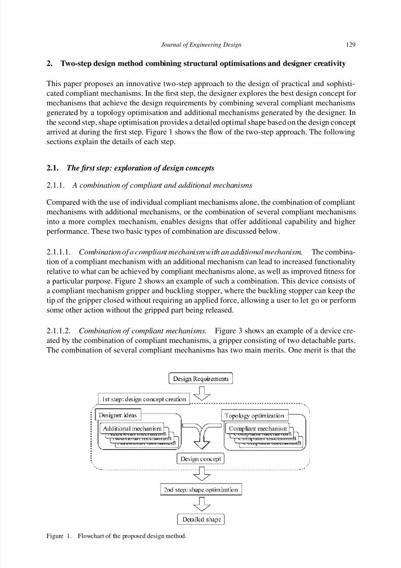
This paper proposes an innovative two-step approach to the design of practical and sophisti-cated compliant mechanisms. In the first step, the designer explores the best design concept formechanisms that achieve the design requirements by combining several compliant mechanismsgenerated by a topology optimisation and additional mechanisms generated by the designer. Inthe second step, shape optimisation provides a detailed optimal shape based on the design conceptarrived at during the first step. Figure 1 shows the flow of the two-step approach. The followingsections explain the details of each step.
2.1. The first step: exploration of design concepts
2.1.1. A combination of compliant and additional mechanisms
Compared with the use of individual compliant mechanisms alone, the combination of compliantmechanisms with additional mechanisms, or the combination of several compliant mechanismsinto a more complex mechanism, enables designs that offer additional capability and higherperformance. These two basic types of combination are discussed below.
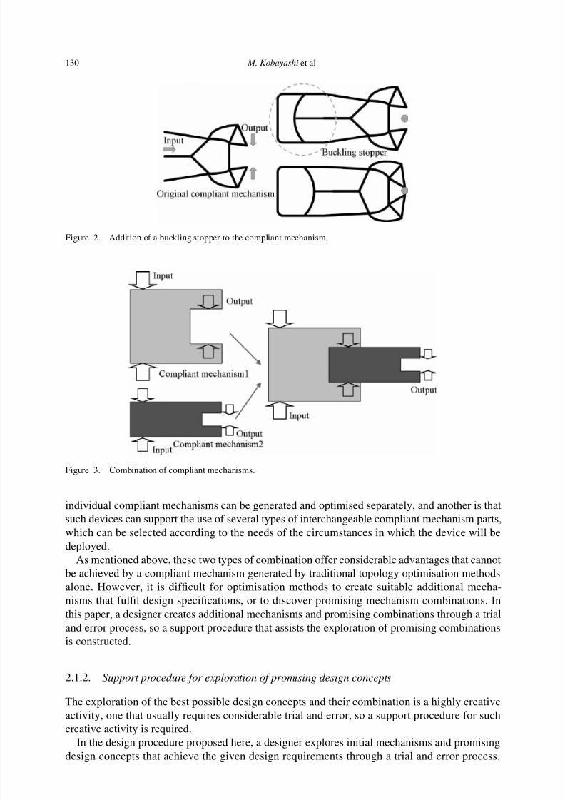
2.1.1.1. Combination of a compliant mechanism with an additional mechanism. The combina-tion of a compliant mechanism with an additional mechanism can lead to increased functionalityrelative to what can be achieved by compliant mechanisms alone, as well as improved fitness fora particular purpose. Figure 2 shows an example of such a combination. This device consists of a compliant mechanism gripper and buckling stopper, where the buckling stopper can keep the
tip of the gripper closed without requiring an applied force, allowing a user to let go or performsome other action without the gripped part being released.
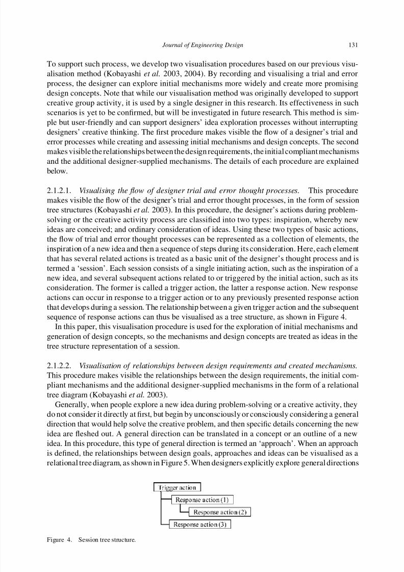
2.1.1.2. Combination of compliant mechanisms. Figure 3 shows an example of a device cre-ated by the combination of compliant mechanisms, a gripper consisting of two detachable parts.The combination of several compliant mechanisms has two main merits. One merit is that the
7/17/2019 An innovative design method for compliant mechanisms combining structural optimisations and designer creativity..pdf
http://slidepdf.com/reader/full/an-innovative-design-method-for-compliant-mechanisms-combining-structural-optimisations 6/31
130 M. Kobayashi et al.
Figure 2. Addition of a buckling stopper to the compliant mechanism.
Figure 3. Combination of compliant mechanisms.
individual compliant mechanisms can be generated and optimised separately, and another is thatsuch devices can support the use of several types of interchangeable compliant mechanism parts,which can be selected according to the needs of the circumstances in which the device will bedeployed.
As mentioned above, these two types of combination offer considerable advantages that cannotbe achieved by a compliant mechanism generated by traditional topology optimisation methodsalone. However, it is difficult for optimisation methods to create suitable additional mecha-nisms that fulfil design specifications, or to discover promising mechanism combinations. Inthis paper, a designer creates additional mechanisms and promising combinations through a trialand error process, so a support procedure that assists the exploration of promising combinationsis constructed.
2.1.2. Support procedure for exploration of promising design concepts
The exploration of the best possible design concepts and their combination is a highly creativeactivity, one that usually requires considerable trial and error, so a support procedure for such
ti ti it i i d
7/17/2019 An innovative design method for compliant mechanisms combining structural optimisations and designer creativity..pdf
http://slidepdf.com/reader/full/an-innovative-design-method-for-compliant-mechanisms-combining-structural-optimisations 7/31
Journal of Engineering Design 131
To support such process, we develop two visualisation procedures based on our previous visu-alisation method (Kobayashi et al. 2003, 2004). By recording and visualising a trial and errorprocess, the designer can explore initial mechanisms more widely and create more promisingdesign concepts. Note that while our visualisation method was originally developed to support
creative group activity, it is used by a single designer in this research. Its effectiveness in suchscenarios is yet to be confirmed, but will be investigated in future research. This method is sim-ple but user-friendly and can support designers’ idea exploration processes without interruptingdesigners’ creative thinking. The first procedure makes visible the flow of a designer’s trial anderror processes while creating and assessing initial mechanisms and design concepts. The secondmakes visiblethe relationshipsbetween the design requirements, the initial compliant mechanismsand the additional designer-supplied mechanisms. The details of each procedure are explainedbelow.
2.1.2.1. Visualising the flow of designer trial and error thought processes. This procedure
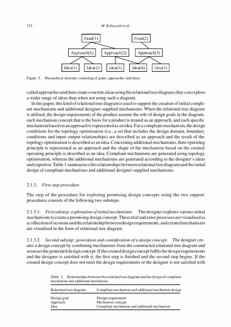
makes visible the flow of the designer’s trial and error thought processes, in the form of sessiontree structures (Kobayashi et al. 2003). In this procedure, the designer’s actions during problem-solving or the creative activity process are classified into two types: inspiration, whereby newideas are conceived; and ordinary consideration of ideas. Using these two types of basic actions,the flow of trial and error thought processes can be represented as a collection of elements, theinspiration of a new idea and then a sequence of steps during its consideration. Here, each elementthat has several related actions is treated as a basic unit of the designer’s thought process and istermed a ‘session’. Each session consists of a single initiating action, such as the inspiration of anew idea, and several subsequent actions related to or triggered by the initial action, such as itsconsideration. The former is called a trigger action, the latter a response action. New response
actions can occur in response to a trigger action or to any previously presented response actionthat develops during a session. The relationship between a given trigger action and the subsequentsequence of response actions can thus be visualised as a tree structure, as shown in Figure 4.
In this paper, this visualisation procedure is used for the exploration of initial mechanisms andgeneration of design concepts, so the mechanisms and design concepts are treated as ideas in thetree structure representation of a session.
2.1.2.2. Visualisation of relationships between design requirements and created mechanisms.
This procedure makes visible the relationships between the design requirements, the initial com-pliant mechanisms and the additional designer-supplied mechanisms in the form of a relationaltree diagram (Kobayashi et al. 2003).
Generally, when people explore a new idea during problem-solving or a creative activity, theydo not consider it directly at first, but begin by unconsciously or consciously considering a generaldirection that would help solve the creative problem, and then specific details concerning the newidea are fleshed out. A general direction can be translated in a concept or an outline of a newidea. In this procedure, this type of general direction is termed an ‘approach’. When an approachis defined, the relationships between design goals, approaches and ideas can be visualised as arelational tree diagram, as shown in Figure 5. When designers explicitly explore general directions
7/17/2019 An innovative design method for compliant mechanisms combining structural optimisations and designer creativity..pdf
http://slidepdf.com/reader/full/an-innovative-design-method-for-compliant-mechanisms-combining-structural-optimisations 8/31
132 M. Kobayashi et al.
Figure 5. Hierarchical structure consisting of goals, approaches and ideas.
called approachesand then create concrete ideas using the relational tree diagram,they can explorea wider range of ideas than when not using such a diagram.
In this paper, this kind of relational tree diagram is used to support the creation of initial compli-ant mechanisms and additional designer-supplied mechanisms. When the relational tree diagram
is utilised, the design requirements of the product assume the role of design goals in the diagram,each mechanism concept that is the basis for a product is treated as an approach, and each specificmechanism basedon an approach is representedas an idea. For a compliant mechanism, the designconditions for the topology optimisation (i.e., a set that includes the design domain, boundaryconditions and input–output relationships) are described as an approach and the result of thetopology optimisation is described as an idea. Concerning additional mechanisms, their operatingprinciple is represented as an approach and the shape of the mechanism based on the createdoperating principle is described as an idea. Compliant mechanisms are generated using topologyoptimisation, whereas the additional mechanisms are generated according to the designer’s ideasand expertise. Table 1 summarises the relationships between relational tree diagram and the initial
design of compliant mechanisms and additional designer-supplied mechanisms.
2.1.3. First-step procedure
The step of the procedure for exploring promising design concepts using the two supportprocedures consists of the following two substeps.
2.1.3.1. First substep: exploration of initial mechanisms. The designer explores various initialmechanisms to create a promising design concept. These trial and error processes are visualised asa collectionof sessions andthe relationship betweendesign requirements, andcreated mechanisms
are visualised in the form of relational tree diagram.
2.1.3.2. Second substep: generation and consideration of a design concept. The designer cre-ates a design concept by combining mechanisms from the constructed relational tree diagram andassesses the generated design concept. If the created design concept fulfils the design requirementsand the designer is satisfied with it, the first step is finished and the second step begins. If thecreated design concept does not meet the design requirements or the designer is not satisfied with
Table 1. Relationships between the relational tree diagram and the design of compliantmechanism and additional mechanism.
Relational tree diagram Compliant mechanism and additional mechanism design
D i l D i i t
7/17/2019 An innovative design method for compliant mechanisms combining structural optimisations and designer creativity..pdf
http://slidepdf.com/reader/full/an-innovative-design-method-for-compliant-mechanisms-combining-structural-optimisations 9/31
Journal of Engineering Design 133
it, the designer returns to the first substep, explores new mechanisms and generates new designconcepts until the outcome is satisfactory.
The processes occurring in the second substep are also visualised as a collection of sessions,which clarifies the assessment processes and helps the designer to explore new mechanisms and
create a promising design concept.
2.1.4. Compliant mechanism design using topology optimisation
Here, we discuss a topology optimisation method for the design of compliant mechanisms. First,the concept of topology optimisation is briefly discussed. Next, the design requirements, thecorrespondingobjectivefunctions,andtheentire optimisation problemare formulated. In addition,the optimisation algorithm is constructed based on the above formulations.
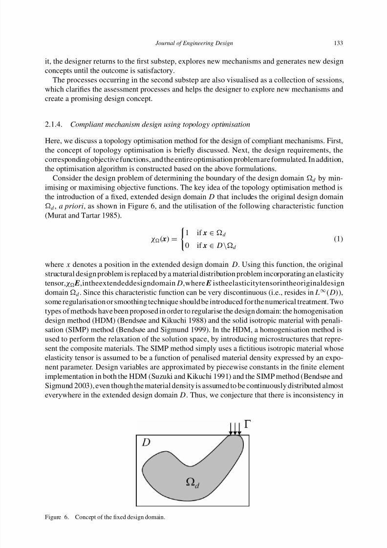
Consider the design problem of determining the boundary of the design domain d by min-imising or maximising objective functions. The key idea of the topology optimisation method isthe introduction of a fixed, extended design domain D that includes the original design domaind , a priori, as shown in Figure 6, and the utilisation of the following characteristic function(Murat and Tartar 1985).
χ( x) =
1 if x ∈ d
0 if x ∈ D\d
(1)
where x denotes a position in the extended design domain D. Using this function, the originalstructural design problem is replaced by a material distribution problem incorporating an elasticitytensor,χ E,intheextendeddesigndomainD,where E istheelasticitytensorintheoriginaldesigndomain d . Since this characteristic function can be very discontinuous (i.e., resides in L∞(D)),some regularisation or smoothing technique shouldbe introduced for the numerical treatment. Twotypes of methods have been proposed in order to regularise the design domain: the homogenisationdesign method (HDM) (Bendsøe and Kikuchi 1988) and the solid isotropic material with penali-sation (SIMP) method (Bendsøe and Sigmund 1999). In the HDM, a homogenisation method isused to perform the relaxation of the solution space, by introducing microstructures that repre-sent the composite materials. The SIMP method simply uses a fictitious isotropic material whoseelasticity tensor is assumed to be a function of penalised material density expressed by an expo-nent parameter. Design variables are approximated by piecewise constants in the finite elementimplementation in both the HDM (Suzuki and Kikuchi 1991) and the SIMP method (Bendsøe and
Sigmund 2003), even though the material density is assumed to be continuously distributed almosteverywhere in the extended design domain D. Thus, we conjecture that there is inconsistency in
7/17/2019 An innovative design method for compliant mechanisms combining structural optimisations and designer creativity..pdf
http://slidepdf.com/reader/full/an-innovative-design-method-for-compliant-mechanisms-combining-structural-optimisations 10/31
134 M. Kobayashi et al.
the procedures (i.e., the assumption of continuous material distributions and the piecewise dis-tribution of design variables), and that the approximation based on a piecewise constant in eachelement is a cause of numerical instability problems, such as checkerboard patterns.
To overcome the above problems, and to maintain procedural consistency, we locate the discre-
tised design variables not at the centre of the elements but at their nodes, and assume continuousmaterial distributions using a continuous interpolation function at each node (Matsui and Terada2004). That is, we approximate the design variable r ( x) as,
r( x) ≈ r h( x) = N r( x) R =
ni=1
N ri ( x)Ri (2)
where h represents the discretised quantity using finite element method, N r is a vector whosecomponents are N ri ( x)(i = 1, . . . , n ), R is a vector of nodal (discrete) design variables Ri(i =
1, . . . , n ), and n is the total number of nodes, which is also the same as the number of design
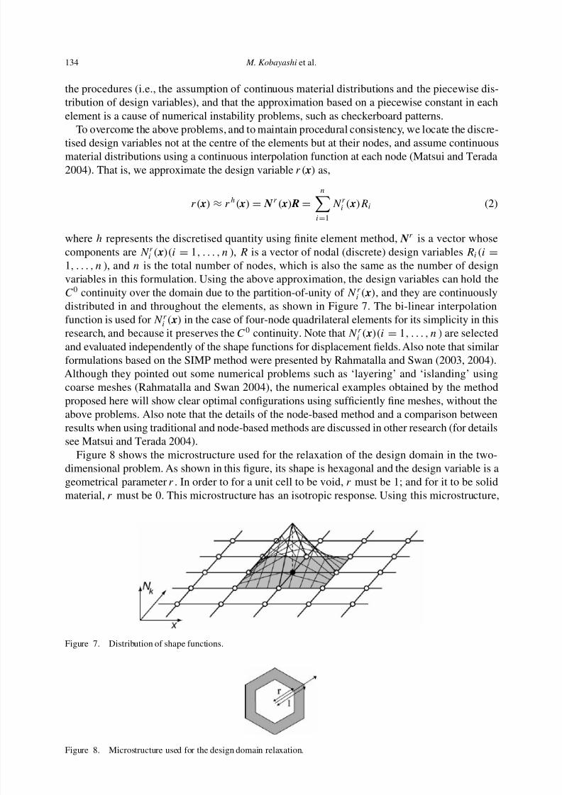
variables in this formulation. Using the above approximation, the design variables can hold theC0 continuity over the domain due to the partition-of-unity of N ri ( x), and they are continuouslydistributed in and throughout the elements, as shown in Figure 7. The bi-linear interpolationfunction is used for N ri ( x) in the case of four-node quadrilateral elements for its simplicity in thisresearch, and because it preserves the C0 continuity. Note that N ri ( x)(i = 1, . . . , n ) are selectedand evaluated independently of the shape functions for displacement fields. Also note that similarformulations based on the SIMP method were presented by Rahmatalla and Swan (2003, 2004).Although they pointed out some numerical problems such as ‘layering’ and ‘islanding’ usingcoarse meshes (Rahmatalla and Swan 2004), the numerical examples obtained by the methodproposed here will show clear optimal configurations using sufficiently fine meshes, without the
above problems. Also note that the details of the node-based method and a comparison betweenresults when using traditional and node-based methods are discussed in other research (for detailssee Matsui and Terada 2004).
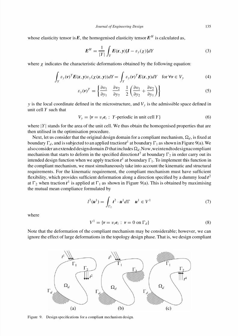
Figure 8 shows the microstructure used for the relaxation of the design domain in the two-dimensional problem. As shown in this figure, its shape is hexagonal and the design variable is ageometrical parameter r . In order to for a unit cell to be void, r must be 1; and for it to be solidmaterial, r must be 0. This microstructure has an isotropic response. Using this microstructure,
Figure 7. Distribution of shape functions.
7/17/2019 An innovative design method for compliant mechanisms combining structural optimisations and designer creativity..pdf
http://slidepdf.com/reader/full/an-innovative-design-method-for-compliant-mechanisms-combining-structural-optimisations 11/31
Journal of Engineering Design 135
whose elasticity tensor is E, the homogenised elasticity tensor EH is calculated as,
EH =1
|Y | Y E( x, y)[ I − εy(χ)]dY (3)
where χ indicates the characteristic deformations obtained by the following equation: Y
εy(v)T E( x, y)εy(χ( x, y))dY =
Y
εy(v)T E( x, y)dY for ∀v ∈ V y (4)
εy(v)T =
∂v1
∂y1
∂v2
∂y2
1
2
∂v1
∂y2+
∂v2
∂y1
(5)
y is the local coordinate defined in the microstructure, and V y is the admissible space defined inunit cell Y such that
V y = {v = viei : Y -periodic in unit cell Y } (6)where |Y | stands for the area of the unit cell. We thus obtain the homogenised properties that arethen utilised in the optimisation procedure.
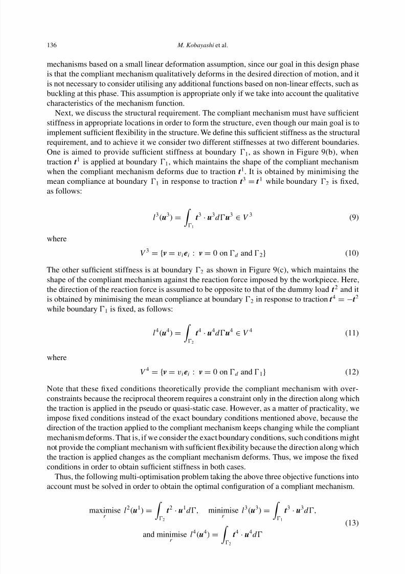
Next, let us consider that the original design domain for a compliant mechanism, d , is fixed atboundary d , and is subjected to an applied traction t1 at boundary 1 as shown in Figure 9(a). Wealsoconsider an extended design domainD that includesd .Now,weintendtodesignacompliantmechanism that starts to deform in the specified direction t2 at boundary 2 in order carry out itsintended design function when we apply traction t1 at boundary 1. To implement this function inthe compliant mechanism, we must simultaneously take into account the kinematic and structuralrequirements. For the kinematic requirement, the compliant mechanism must have sufficient
flexibility, which provides sufficient deformation along a direction specified by a dummy load t2
at 2 when traction t1 is applied at 1 as shown in Figure 9(a). This is obtained by maximisingthe mutual mean compliance formulated by
l2(u1) =
2
t2 · u1d u1 ∈ V 1 (7)
where
V 1 = {v = viei : v = 0 on d } (8)
Note that the deformation of the compliant mechanism may be considerable; however, we can
ignore the effect of large deformations in the topology design phase. That is, we design compliant
7/17/2019 An innovative design method for compliant mechanisms combining structural optimisations and designer creativity..pdf
http://slidepdf.com/reader/full/an-innovative-design-method-for-compliant-mechanisms-combining-structural-optimisations 12/31
136 M. Kobayashi et al.
mechanisms based on a small linear deformation assumption, since our goal in this design phaseis that the compliant mechanism qualitatively deforms in the desired direction of motion, and itis not necessary to consider utilising any additional functions based on non-linear effects, such asbuckling at this phase. This assumption is appropriate only if we take into account the qualitative
characteristics of the mechanism function.Next, we discuss the structural requirement. The compliant mechanism must have sufficient
stiffness in appropriate locations in order to form the structure, even though our main goal is toimplement sufficient flexibility in the structure. We define this sufficient stiffness as the structuralrequirement, and to achieve it we consider two different stiffnesses at two different boundaries.One is aimed to provide sufficient stiffness at boundary 1, as shown in Figure 9(b), whentraction t1 is applied at boundary 1, which maintains the shape of the compliant mechanismwhen the compliant mechanism deforms due to traction t1. It is obtained by minimising themean compliance at boundary 1 in response to traction t3 = t1 while boundary 2 is fixed,as follows:
l3(u3) =
1
t3 · u3du3 ∈ V 3 (9)
where
V 3 = {v = viei : v = 0 on d and 2} (10)
The other sufficient stiffness is at boundary 2 as shown in Figure 9(c), which maintains theshape of the compliant mechanism against the reaction force imposed by the workpiece. Here,the direction of the reaction force is assumed to be opposite to that of the dummy load t2 and it
is obtained by minimising the mean compliance at boundary 2 in response to traction t4
= − t2
while boundary 1 is fixed, as follows:
l4(u4) =
2
t4 · u4du4 ∈ V 4 (11)
where
V 4 = {v = viei : v = 0 on d and 1} (12)
Note that these fixed conditions theoretically provide the compliant mechanism with over-
constraints because the reciprocal theorem requires a constraint only in the direction along whichthe traction is applied in the pseudo or quasi-static case. However, as a matter of practicality, weimpose fixed conditions instead of the exact boundary conditions mentioned above, because thedirection of the traction applied to the compliant mechanism keeps changing while the compliantmechanism deforms. That is, if we consider the exact boundary conditions, such conditions mightnot provide the compliant mechanism with sufficient flexibility because the direction along whichthe traction is applied changes as the compliant mechanism deforms. Thus, we impose the fixedconditions in order to obtain sufficient stiffness in both cases.
Thus, the following multi-optimisation problem taking the above three objective functions intoaccount must be solved in order to obtain the optimal configuration of a compliant mechanism.
maximiser
l2(u1) =
2
t2 · u1d, minimiser
l3(u3) =
1
t3 · u3d,
(13)
7/17/2019 An innovative design method for compliant mechanisms combining structural optimisations and designer creativity..pdf
http://slidepdf.com/reader/full/an-innovative-design-method-for-compliant-mechanisms-combining-structural-optimisations 13/31
Journal of Engineering Design 137
subject to
t3 = t1 (14)
t4 = − t2 (15)
a(u1, v1) = l1(v1) for u1 ∈ V 1 ∀v1 ∈ V 1 (16)
a(u2, v2) = l2(v2) for u1 ∈ V 2 ∀v2 ∈ V 1 (17)
a(u3, v3) = l3(v3) for u3 ∈ V 3 ∀v3 ∈ V 3 (18)
a(u4, v4) = l4(v4) for u4 ∈ V 4 ∀v4 ∈ V 4 (19)
0 ≤ r ≤ 1 (20)
g(r) = d
(1 − r( x)2)d − s = D(1 − r( x)2)d − s ≤ 0 (21)
where
a(u, v) =
d
ε(v)T Eε(u)d (22)
ε(v)T =
∂v1
∂x1
∂v2
∂x2
1
2
∂v1
∂x2+
∂v2
∂x1
(23)
and s is the total volume constraint.In order to incorporate the above three objective functions, the following multi-objective
function is used. See Rahmatalla and Swan (2004) for details.
maximiser f =l2(u1)
w3l3(u3) + w4l4(u4)(24)
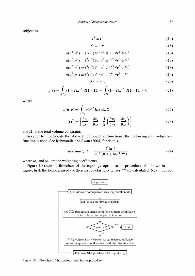
where w3 and w4 are the weighting coefficientsFigure 10 shows a flowchart of the topology optimisation procedure. As shown in this
figure, first, the homogenised coefficients for elasticity tensor EH are calculated. Next, the four
7/17/2019 An innovative design method for compliant mechanisms combining structural optimisations and designer creativity..pdf
http://slidepdf.com/reader/full/an-innovative-design-method-for-compliant-mechanisms-combining-structural-optimisations 14/31
138 M. Kobayashi et al.
equilibrium equations formulated by Equations (16)–(19) are solved using the finite elementmethod. The mutual mean compliance formulated by Equation (7), the mean compliances formu-lated by Equations (9) and (11), the total volume constraint, and the objective function formulatedby Equation (24) are all computed. If the objective function converges, this procedure terminates;
otherwise, the sensitivities of the mutual mean compliance, the mean compliances, the total vol-ume constraint, and the objective function are all computed. The design variables are updatedusing sequential linear programming, and the procedure returns to the first step.
2.1.5. Additional mechanism design
The designer creates all of the additional mechanisms using his or her expertise, experienceand ideas. The detailed shape and behaviour of an additional mechanism are determined byshape optimisation during the second step so that only principles of operation and rough shapessufficient to make initial shape optimisation models during the second step need to be created by
the designer.
2.2. Second step: determination of detailed shape using shape optimisation
In the second step, the detailed shape of the design concept arrived at first step is determinedusing shape optimisation, by considering non-linear analysis, stress constraints and makingaccurate quantitative performance evaluations. The second step consists of four substeps: prepa-ration of an initial shape optimisation model, configuration of the shape optimisation designconditions, execution of the shape optimisation, and assessment of the result of the shapeoptimisation.
2.2.1. Preparation of initial shape optimisation model
To begin the process, the designer manually creates an initial model for shape optimisation,based on the design concept consisting of the topology optimisations and the additional designer-supplied mechanisms. The modelling procedures are different for compliant mechanisms and theadditional designer-supplied mechanisms, so that the designer makes a model of each mecha-nism individually and then combines them into a unified initial shape optimisation model. Theprocedural details will be explained below.
2.2.1.1. Modelling procedures for compliant mechanisms. For stiffness maximisation prob-lems (i.e., the design of rigid structures), several methods that integrate topology and shapeoptimisations have been developed (Bremicker et al. 1991 and Yıldız et al. 2003), and certaincommercial software packages such as TOSCA, OPTISHAPE-TS or a combination of AltairOptiStruct and Hyperstudy provide a similar function. In these methods and software packages,image-processing techniques are used to prepare an initial shape optimisation model by extract-ing results from topology optimisation. However, extraction methods based on image-processingtechniques fail to consider the function or characteristics of structural parts that make up theentire structure, and it is difficult to apply such methods to the design of compliant mecha-nisms, since certain parts of a compliant mechanism must have specific characteristics (i.e.,
appropriate stiffness or flexibility) to achieve the specified compliant mechanism behaviour thatrequires specified structural deformation. Such characteristics must be retained even after the
t ti f th i iti l d l f th t l ti i ti lt F th li
7/17/2019 An innovative design method for compliant mechanisms combining structural optimisations and designer creativity..pdf
http://slidepdf.com/reader/full/an-innovative-design-method-for-compliant-mechanisms-combining-structural-optimisations 15/31
Journal of Engineering Design 139
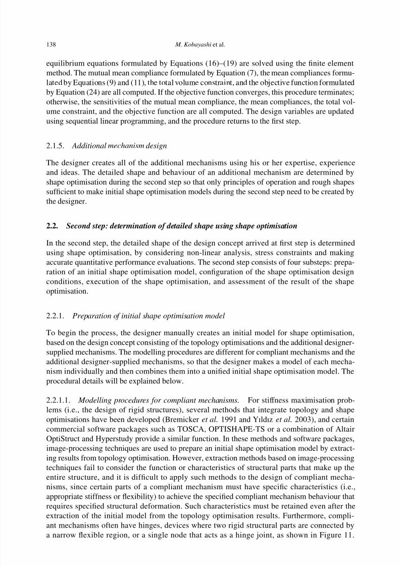
Figure 11. Geometrical features of a compliant mechanism.
Hinges may cause very high stress concentrations that exceed the strength of their materials,so shapes extracted by image-processing techniques are seldom suitable for use as initial shapeoptimisation models. To resolve these problems, a new extraction method is constructed, onethat focuses on the characteristics of certain components of the compliant mechanisms being
developed.From the viewpoint of stiffness and flexibility, two types of components can be identified in
the basic structure of a compliant mechanism, namely hinges and non-flexible masses, as shownin Figure 11. Hinges have high flexibility, whereas non-flexible masses have high stiffness. Thedeformation properties of a given component can be controlled by changing its width, so thewidth of each region in a compliant mechanism is used as a design variable. In addition to thewidth, the positional relationshipsbetween flexible and non-flexible regions affect the deformationproperties, so these positions are alsousedas designvariables.However, the more designvariables,the more difficult it is to reduce the computation time, enable stable convergence during shapeoptimisation, and obtain an appropriate optimal structure, so the designer must carefully consider
the influence that each design variable has on the performance of a compliant mechanism andappropriately allocate design variables or fixed values.
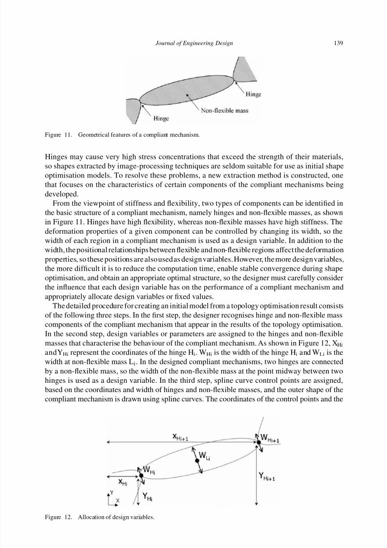
The detailed procedure for creating an initial model from a topology optimisation result consistsof the following three steps. In the first step, the designer recognises hinge and non-flexible masscomponents of the compliant mechanism that appear in the results of the topology optimisation.In the second step, design variables or parameters are assigned to the hinges and non-flexiblemasses that characterise the behaviour of the compliant mechanism. As shown in Figure 12, XHi
andYHi represent the coordinates of the hinge Hi. WHi is the width of the hinge Hi and WLi is thewidth at non-flexible mass Li. In the designed compliant mechanisms, two hinges are connectedby a non-flexible mass, so the width of the non-flexible mass at the point midway between two
hinges is used as a design variable. In the third step, spline curve control points are assigned,based on the coordinates and width of hinges and non-flexible masses, and the outer shape of thecompliant mechanism is drawn using spline curves. The coordinates of the control points and the
7/17/2019 An innovative design method for compliant mechanisms combining structural optimisations and designer creativity..pdf
http://slidepdf.com/reader/full/an-innovative-design-method-for-compliant-mechanisms-combining-structural-optimisations 16/31
140 M. Kobayashi et al.
Figure 13. Allocation of spline curve control points and drawing of an outer shape.
widths of the hinges are also regarded as design variables. The black points shown in Figure 13are examples of control points and the dotted lines are examples of an outer shape drawn in thisfashion.
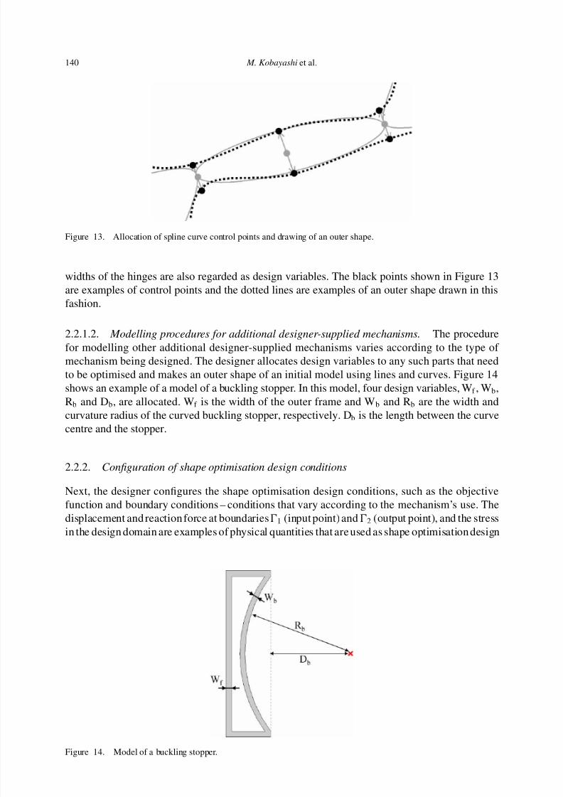
2.2.1.2. Modelling procedures for additional designer-supplied mechanisms. The procedurefor modelling other additional designer-supplied mechanisms varies according to the type of mechanism being designed. The designer allocates design variables to any such parts that needto be optimised and makes an outer shape of an initial model using lines and curves. Figure 14shows an example of a model of a buckling stopper. In this model, four design variables, Wf , Wb,Rb and Db, are allocated. Wf is the width of the outer frame and Wb and Rb are the width and
curvature radius of the curved buckling stopper, respectively. Db is the length between the curvecentre and the stopper.
2.2.2. Configuration of shape optimisation design conditions
Next, the designer configures the shape optimisation design conditions, such as the objectivefunction and boundary conditions – conditions that vary according to the mechanism’s use. Thedisplacement and reaction force at boundaries1 (input point) and2 (output point), and the stressin the design domain are examples of physical quantities that are used as shape optimisation design
7/17/2019 An innovative design method for compliant mechanisms combining structural optimisations and designer creativity..pdf
http://slidepdf.com/reader/full/an-innovative-design-method-for-compliant-mechanisms-combining-structural-optimisations 17/31
Journal of Engineering Design 141
conditions. In this case, the optimisation problem can be formulated as below.
Maximise d out (25)
subject to
σ M ≤ σ allow (26)
F in ≤ F max (27)
where d out is the displacement at boundary 2, σ M is the von Mises stress, σ allow is the allowablestress, F in is the reaction force that is generated by the applied input displacement at 1 and F max
is its upper limit.If the output force at2 is applied to a workpiece, as would be the case for a gripper, 2 receives
a reaction force. Therefore, it is appropriate to treat this reaction force as a spring force with spring
element attached to 2 for the purposes of analysis and optimisation.
2.2.3. Execution of the shape optimisation
Shape optimisation is executed, using the entire initial model under the design conditions. Inorder to strictly analyse various kinds of physical quantities such as displacement, reaction forceand stress, the analysis method used during the shape optimisation must be able to considernon-linear and large deformations. In this paper, ANSYS is used as the structural analysis andshape optimisation software. When using ANSYS, the first-order optimisation method is used asthe optimisation algorithm. This method calculates and makes use of derivative information to
appropriately steer the search direction in design space.
2.2.4. Assessment of the shape optimisation result
When the shape optimisation is finished, the designer assesses the result; if the result fulfilsthe design requirements and the designer is satisfied, all design processes are finished. If theunsatisfactory for any reason, the process returns to the first step, and new, more promising designconcepts are explored.
3. Case study
Todemonstratetheflowoftheproposedprocedure,twoexamplesarepresented.Thefirstaddressesthedesignofacompliantgripperandclipset,whilethesecondfocusesonthedesignofacompliantgripper having a stopper function.
3.1. First example
3.1.1. Design requirements for the first case study
In the first example, a compliant gripper and clip set are designed, with the gripper and clip beingindependent parts, the clip being held by the gripper during manipulation. Since the gripper itself ish d h ld th t h d i t t t i i i t Th i t t t
7/17/2019 An innovative design method for compliant mechanisms combining structural optimisations and designer creativity..pdf
http://slidepdf.com/reader/full/an-innovative-design-method-for-compliant-mechanisms-combining-structural-optimisations 18/31
142 M. Kobayashi et al.
For the clip, the location and direction of the input are also unconstrained, and for the output theclip tip is required to close when released, and open when a suitable input force is applied. Thematerial is ultrahigh molecular weight polyethylene, with a Young’s modulus of 720 MPa andPoisson’s ratio of 0.3. The thickness of each part is 10 mm.
3.1.2. First step
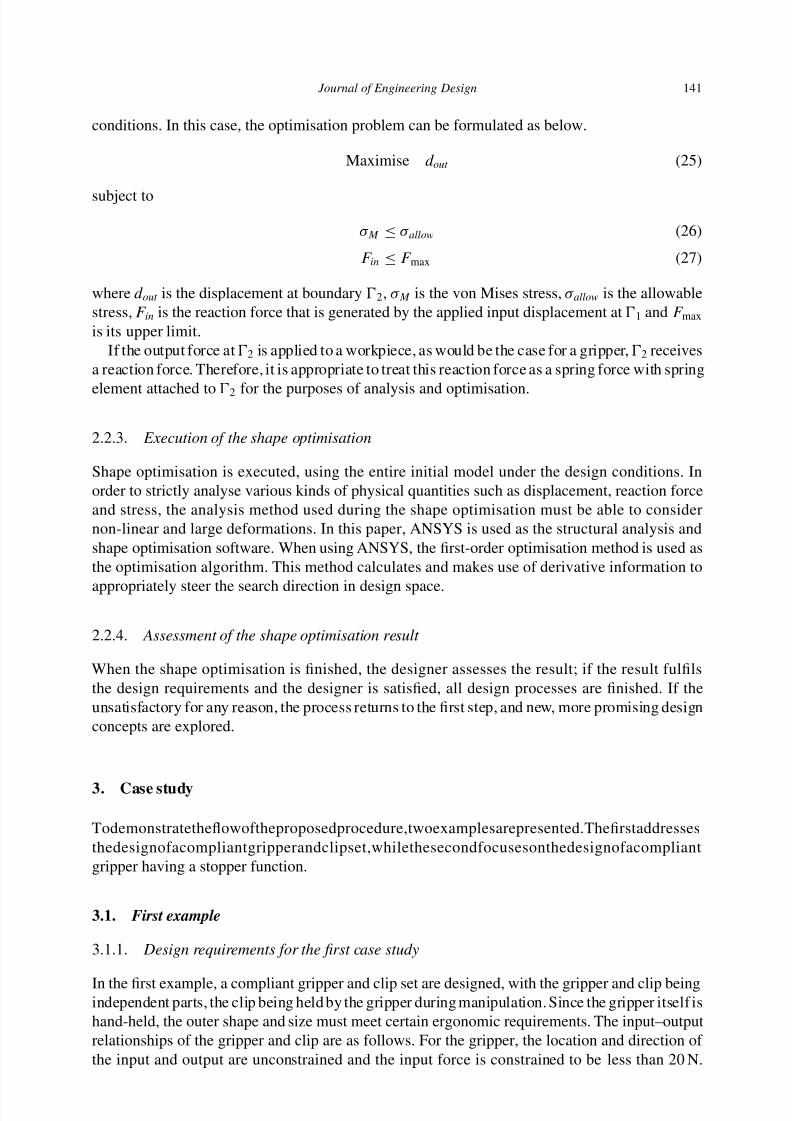
In the first step, compliant mechanisms and additional mechanisms are created and the mostpromising design concept is explored. This step is supported by two visualisation procedures.The relational tree diagram resulting from the first step is shown in Figure 15.
In this example, two approaches are created, one for the gripper and the other for the clip, witheach approach focused on the individual part. Conceptually, the gripper tip closes when a userforcibly squeezes the gripper, as shown in Figure 16(a), and the clip tip closes when the clip isforcibly grasped by the gripper, as shown in Figure 16(b). These concepts are used for the design
Figure 15. Hierarchical structure of the problem.
Figure 16. Two compliant mechanism concepts: (a) concept 1 and (b) concept 2.
7/17/2019 An innovative design method for compliant mechanisms combining structural optimisations and designer creativity..pdf
http://slidepdf.com/reader/full/an-innovative-design-method-for-compliant-mechanisms-combining-structural-optimisations 19/31
Journal of Engineering Design 143
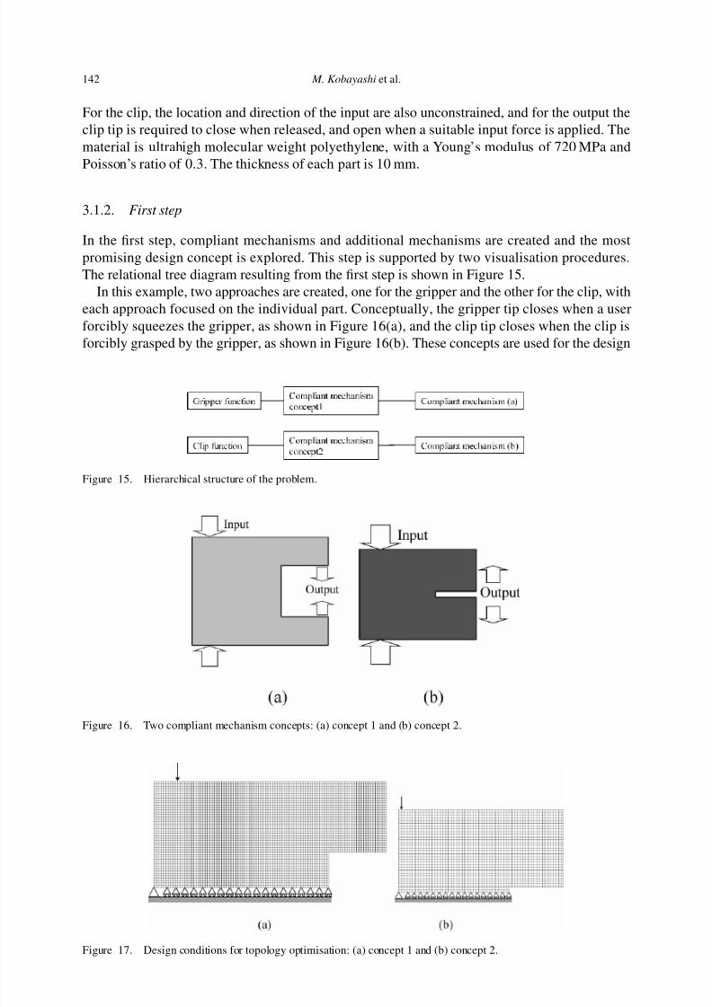
Figure 18. Created mechanisms: (a) a compliant gripper and (b) a compliant clip.
Figure 19. Design concept.
conditions of topology optimisation, as shown in Figure 17(a) and (b). Figures 18(a) and (b) showthe optimal structures of the gripper and the clip resulting from the topology optimisation. Inthis example, we assume symmetrical shapes along a longitudinal axis, so the optimal structureresulting from the topology optimisation only shows the upper half of the mechanism. The designconcept shown in Figure 19 is achieved by combining two compliant mechanisms.
The process of creating the above mechanisms and concepts are recorded as a collection of sessions, but only a portion of the record is shown in Figure 20.
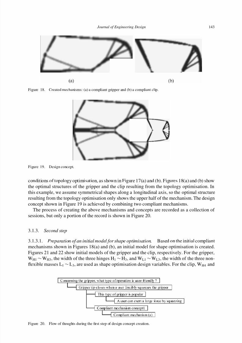
3.1.3. Second step
3.1.3.1. Preparation of an initial model for shape optimisation. Based on the initial compliantmechanisms shown in Figures 18(a) and (b), an initial model for shape optimisation is created.Figures 21 and 22 show initial models of the gripper and the clip, respectively. For the gripper,WH1 ∼ WH3, the width of the three hinges H1 ∼ H3, and WL1 ∼ WL3, the width of the three non-flexible masses L1 ∼ L3, are used as shape optimisation design variables. For the clip, WH4 and
7/17/2019 An innovative design method for compliant mechanisms combining structural optimisations and designer creativity..pdf
http://slidepdf.com/reader/full/an-innovative-design-method-for-compliant-mechanisms-combining-structural-optimisations 20/31
144 M. Kobayashi et al.
Figure 21. The gripper model.
Figure 22. The clip model.
WH5, the width of the two hinges H4 and H3, and WL4 ∼ WL6, the width of the three non-flexiblemasses L1 ∼ L3, are used for the shape optimisation design variables. To represent the constraintsof the clip model used for the topology optimisation, a 0.5-mm segment is added to the lowestedge of the clip model, to fulfil a topology optimisation constraint.
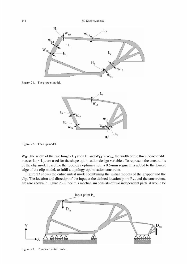
Figure 23 shows the entire initial model combining the initial models of the gripper and theclip. The location and direction of the input at the defined location point Pin, and the constraints,
are also shown in Figure 23. Since this mechanism consists of two independent parts, it would be
7/17/2019 An innovative design method for compliant mechanisms combining structural optimisations and designer creativity..pdf
http://slidepdf.com/reader/full/an-innovative-design-method-for-compliant-mechanisms-combining-structural-optimisations 21/31
Journal of Engineering Design 145
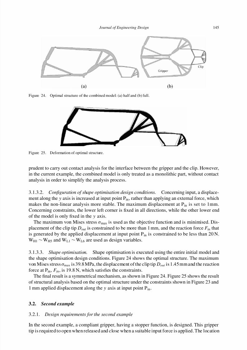
Figure 24. Optimal structure of the combined model: (a) half and (b) full.
Figure 25. Deformation of optimal structure.
prudent to carry out contact analysis for the interface between the gripper and the clip. However,in the current example, the combined model is only treated as a monolithic part, without contactanalysis in order to simplify the analysis process.
3.1.3.2. Configuration of shape optimisation design conditions. Concerning input, a displace-ment along the y axis is increased at input point Pin, rather than applying an external force, whichmakes the non-linear analysis more stable. The maximum displacement at P in is set to 1mm.Concerning constraints, the lower left corner is fixed in all directions, while the other lower endof the model is only fixed in the y axis.
The maximum von Mises stress σ max is used as the objective function and is minimised. Dis-placement of the clip tip Dout is constrained to be more than 1 mm, and the reaction force F in thatis generated by the applied displacement at input point P in is constrained to be less than 20 N.WH1 ∼ WH5 and WL1 ∼ WL6 are used as design variables.
3.1.3.3. Shape optimisation. Shape optimisation is executed using the entire initial model andthe shape optimisation design conditions. Figure 24 shows the optimal structure. The maximumvon Mises stress σ max is 39.8 MPa, the displacement of the clip tip Dout is 1.45 mm and the reactionforce at Pin, F in, is 19.8 N, which satisfies the constraints.
The final result is a symmetrical mechanism, as shown in Figure 24. Figure 25 shows the resultof structural analysis based on the optimal structure under the constraints shown in Figure 23 and1 mm applied displacement along the y axis at input point Pin.
3.2. Second example
3.2.1. Design requirements for the second example
7/17/2019 An innovative design method for compliant mechanisms combining structural optimisations and designer creativity..pdf
http://slidepdf.com/reader/full/an-innovative-design-method-for-compliant-mechanisms-combining-structural-optimisations 22/31
146 M. Kobayashi et al.
and direction of the input forces is unconstrained. The stopper is to function when the grippertip is closed, and keep the tip closed with no applied input force. The outer shape and size of the gripper must meet certain ergonomic requirements, and the material is the same ultra-highmolecular weight polyethylene as in the first example. The thickness of each part is 5 mm, half
the thickness used in the first example.
3.2.2. First step
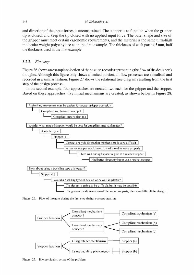
Figure 26 shows an example selection of the session records representing the flow of the designer’sthoughts. Although this figure only shows a limited portion, all flow processes are visualised andrecorded in a similar fashion. Figure 27 shows the relational tree diagram resulting from the firststep of the design process.
In the second example, four approaches are created, two each for the gripper and the stopper.Based on these approaches, five initial mechanisms are created, as shown below in Figure 28.
Figure 26. Flow of thoughts during the first step design concept creation.
7/17/2019 An innovative design method for compliant mechanisms combining structural optimisations and designer creativity..pdf
http://slidepdf.com/reader/full/an-innovative-design-method-for-compliant-mechanisms-combining-structural-optimisations 23/31
Journal of Engineering Design 147
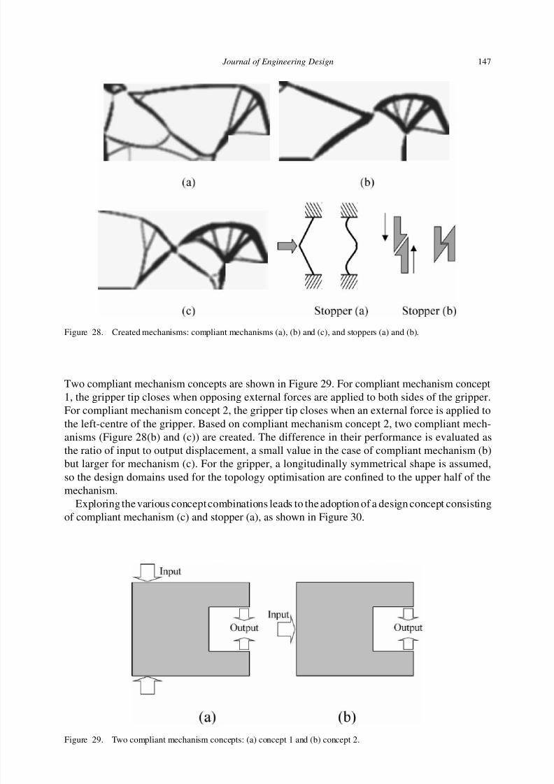
Figure 28. Created mechanisms: compliant mechanisms (a), (b) and (c), and stoppers (a) and (b).
Two compliant mechanism concepts are shown in Figure 29. For compliant mechanism concept1, the gripper tip closes when opposing external forces are applied to both sides of the gripper.
For compliant mechanism concept 2, the gripper tip closes when an external force is applied tothe left-centre of the gripper. Based on compliant mechanism concept 2, two compliant mech-anisms (Figure 28(b) and (c)) are created. The difference in their performance is evaluated asthe ratio of input to output displacement, a small value in the case of compliant mechanism (b)but larger for mechanism (c). For the gripper, a longitudinally symmetrical shape is assumed,so the design domains used for the topology optimisation are confined to the upper half of themechanism.
Exploring the various concept combinations leads to the adoption of a design concept consistingof compliant mechanism (c) and stopper (a), as shown in Figure 30.
7/17/2019 An innovative design method for compliant mechanisms combining structural optimisations and designer creativity..pdf
http://slidepdf.com/reader/full/an-innovative-design-method-for-compliant-mechanisms-combining-structural-optimisations 24/31
148 M. Kobayashi et al.
Figure 30. Design concept.
3.2.3. Second step
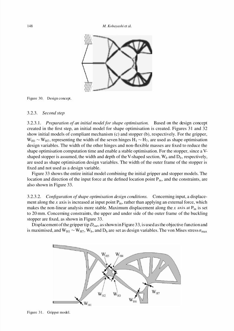
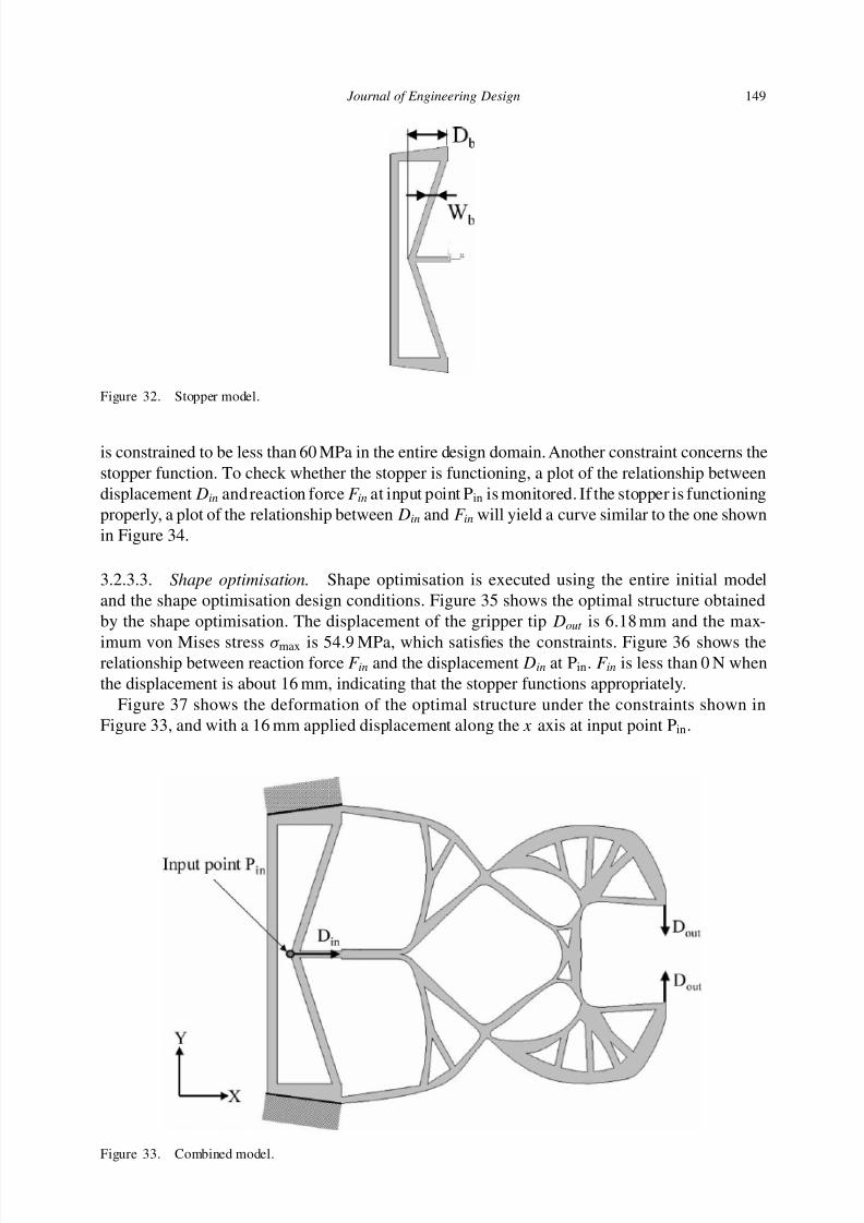
3.2.3.1. Preparation of an initial model for shape optimisation. Based on the design conceptcreated in the first step, an initial model for shape optimisation is created. Figures 31 and 32show initial models of compliant mechanism (c) and stopper (b), respectively. For the gripper,WH1 ∼ WH7, representing the width of the seven hinges H1 ∼ H7, are used as shape optimisationdesign variables. The width of the other hinges and non-flexible masses are fixed to reduce theshape optimisation computation time and enable a stable optimisation. For the stopper, since a V-shaped stopper is assumed, the width and depth of the V-shaped section, Wb and Db, respectively,are used as shape optimisation design variables. The width of the outer frame of the stopper isfixed and not used as a design variable.
Figure 33 shows the entire initial model combining the initial gripper and stopper models. Thelocation and direction of the input force at the defined location point P in, and the constraints, arealso shown in Figure 33.
3.2.3.2. Configuration of shape optimisation design conditions. Concerning input, a displace-ment along the x axis is increased at input point Pin, rather than applying an external force, whichmakes the non-linear analysis more stable. Maximum displacement along the x axis at Pin is setto 20 mm. Concerning constraints, the upper and under side of the outer frame of the bucklingstopper are fixed, as shown in Figure 33.
Displacement of the gripper tipDout , as shown in Figure 33, is used as the objective function and
is maximised, and WH1 ∼ WH7, Wb, and Db are set as design variables. The von Mises stress σ max
7/17/2019 An innovative design method for compliant mechanisms combining structural optimisations and designer creativity..pdf
http://slidepdf.com/reader/full/an-innovative-design-method-for-compliant-mechanisms-combining-structural-optimisations 25/31
Journal of Engineering Design 149
Figure 32. Stopper model.
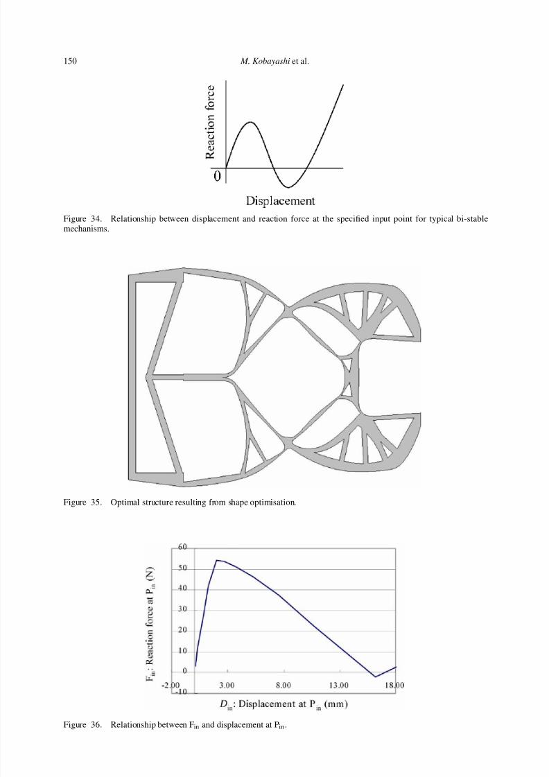
is constrained to be less than 60 MPa in the entire design domain. Another constraint concerns thestopper function. To check whether the stopper is functioning, a plot of the relationship betweendisplacement Din andreaction forceF in at input point Pin is monitored. If the stopper is functioningproperly, a plot of the relationship between Din and F in will yield a curve similar to the one shownin Figure 34.
3.2.3.3. Shape optimisation. Shape optimisation is executed using the entire initial modeland the shape optimisation design conditions. Figure 35 shows the optimal structure obtainedby the shape optimisation. The displacement of the gripper tip Dout is 6.18 mm and the max-
imum von Mises stress σ max is 54.9 MPa, which satisfies the constraints. Figure 36 shows therelationship between reaction force F in and the displacement Din at Pin. F in is less than 0 N whenthe displacement is about 16 mm, indicating that the stopper functions appropriately.
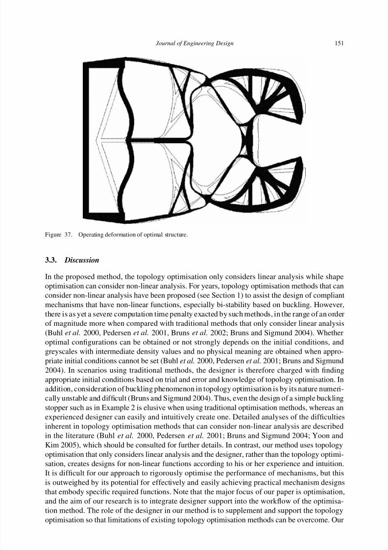
Figure 37 shows the deformation of the optimal structure under the constraints shown inFigure 33, and with a 16 mm applied displacement along the x axis at input point Pin.
7/17/2019 An innovative design method for compliant mechanisms combining structural optimisations and designer creativity..pdf
http://slidepdf.com/reader/full/an-innovative-design-method-for-compliant-mechanisms-combining-structural-optimisations 26/31
150 M. Kobayashi et al.
Figure 34. Relationship between displacement and reaction force at the specified input point for typical bi-stablemechanisms.
Figure 35. Optimal structure resulting from shape optimisation.
7/17/2019 An innovative design method for compliant mechanisms combining structural optimisations and designer creativity..pdf
http://slidepdf.com/reader/full/an-innovative-design-method-for-compliant-mechanisms-combining-structural-optimisations 27/31
Journal of Engineering Design 151
Figure 37. Operating deformation of optimal structure.
3.3. Discussion
In the proposed method, the topology optimisation only considers linear analysis while shape
optimisation can consider non-linear analysis. For years, topology optimisation methods that canconsider non-linear analysis have been proposed (see Section 1) to assist the design of compliantmechanisms that have non-linear functions, especially bi-stability based on buckling. However,there is as yet a severe computation time penalty exacted by such methods, in the range of an orderof magnitude more when compared with traditional methods that only consider linear analysis(Buhl et al. 2000, Pedersen et al. 2001, Bruns et al. 2002; Bruns and Sigmund 2004). Whetheroptimal configurations can be obtained or not strongly depends on the initial conditions, andgreyscales with intermediate density values and no physical meaning are obtained when appro-priate initial conditions cannot be set (Buhl et al. 2000, Pedersen et al. 2001; Bruns and Sigmund2004). In scenarios using traditional methods, the designer is therefore charged with findingappropriate initial conditions based on trial and error and knowledge of topology optimisation. Inaddition, consideration of buckling phenomenon in topology optimisation is by its nature numeri-cally unstable and difficult (Bruns and Sigmund 2004). Thus, even the design of a simple bucklingstopper such as in Example 2 is elusive when using traditional optimisation methods, whereas anexperienced designer can easily and intuitively create one. Detailed analyses of the difficultiesinherent in topology optimisation methods that can consider non-linear analysis are describedin the literature (Buhl et al. 2000, Pedersen et al. 2001; Bruns and Sigmund 2004; Yoon andKim 2005), which should be consulted for further details. In contrast, our method uses topologyoptimisation that only considers linear analysis and the designer, rather than the topology optimi-sation, creates designs for non-linear functions according to his or her experience and intuition.It is difficult for our approach to rigorously optimise the performance of mechanisms, but this
is outweighed by its potential for effectively and easily achieving practical mechanism designsthat embody specific required functions. Note that the major focus of our paper is optimisation,
d th i f h i t i t t d i t i t th kfl f th ti i
7/17/2019 An innovative design method for compliant mechanisms combining structural optimisations and designer creativity..pdf
http://slidepdf.com/reader/full/an-innovative-design-method-for-compliant-mechanisms-combining-structural-optimisations 28/31
152 M. Kobayashi et al.
method also enables the consideration of stress constraints and determination of detailed mecha-nism shapes at the shape optimisation stage, which is another advantage that the proposed methodoffers.
In the first example, a mechanism consisting of two compliant mechanisms (a gripper and a
clip) is designed. When using existing methods in this design problem, the gripper and clip needto be optimised separately, so estimating the load transmission between the two mechanisms andtheir deformation is problematic. In contrast, when using our method, the two mechanisms arecombined into one shape optimisation model and optimised together using shape optimisation.Load transmission between the two mechanisms, and their deformation, can then be estimatedquantitatively and precisely. This is a particular advantage of our method, when multi-part mech-anisms such as a gripper and clip combination need to be designed. The proposed method canalso design mechanisms consisting of more than one compliant mechanism working together tooffer several functions, by introducing a compliant mechanism as one part of another compliantmechanism. Multiple-function devices are rather common at present, such as an electric drill that
can be used to bore holes or turn screws by exchanging a drill bit with a screwdriver bit. Suchversatility is one of the goals that the proposed method seeks to accomplish, by facilitating thedesign of multiple-function compliant mechanisms. However, this advantage is not confirmed inthis example and, since multi-functionality is not the main focus of this research, we only mentionthis as a possible benefit that will be the subject of future research
In the second example, a compliant mechanism having a buckling stopper is designed. Thistype of compliant mechanism can be designed using topology optimisation methods that considernon-linear analysis, but such methods are not practical at this time due to several of the problemsdescribed above.Furthermore, there is little difference in shape andperformance betweenbucklingstoppers created by non-linear topology optimisation and those created by a designer, so an
efficient design method employs a designer to create additional mechanisms having non-linearfunctions that can be added to compliant mechanisms provided by topology optimisation thatonly considers linear responses.
4. Concluding remarks
This paper proposed an innovative two-step approach to the design of practical and sophisticatedcompliant mechanisms. The following points were addressed.
(1) To easily and efficiently create compliant mechanisms having additional functions, beyond
that achievable using traditional topology optimisation alone, this paper proposed a methodthat combines initial compliant mechanisms generated by topology optimisation withadditional mechanisms prepared by the designer.
(2) The process of exploring the most promising combination requires significant designer trialand error, so two support procedures based on visualisation of the design process wereconstructed.
(3) The result of combining initial compliant mechanisms with additional designer-suppliedmechanisms requires further modification before the required function can be met, soshape optimisation is subsequently executed in the second step, using the most promisingcombination achieved in the first step as an initial model. Execution of shape optimisation
alsoenables considerationof stress concentrationand large displacement effects, which wouldbe problematic for traditional topology optimisation alone.(4) To confirm the effectiveness of the proposed method two examples were presented In the
7/17/2019 An innovative design method for compliant mechanisms combining structural optimisations and designer creativity..pdf
http://slidepdf.com/reader/full/an-innovative-design-method-for-compliant-mechanisms-combining-structural-optimisations 29/31
Journal of Engineering Design 153
References
Ananthasuresh, G.K. and Kota, S., 1995. Designing compliant mechanisms. Mechanical Engineering, 117 (11), 93–96.Bendsøe, M.P. and Kikuchi, N., 1988. Generating optimal topologies in structural design using a homogenization method.
Computer Methods in Applied Mechanics and Engineering, 71 (2), 197–224.Bendsøe, M.P. and Sigmund, O., 1999. Material interpolation schemes in topology optimization. Archive of Applied
Mechanics, 69, 635–654.Bendsøe, M.P. and Sigmund, O., 2003. Topology optimization. Theory, methods and applications. Berlin, Heidelberg,
New York: Springer-Verlag.Bourdin, B., 2001. Filters in topology optimization. International Journal for Numerical Methods in Engineering, 50,
2143–2158.Bremicker, M., Chirehdast, M., Kikuchi, M. and Papalambros, P. Y., 1991. Integrated topology and shape optimization in
structural design. Mechanics of Structures and Machines, 19 (4), 551–587.Bruns, T. E. and Tortorelli, D.A., 2001. Topology optimization of non-linear elastic structures and compliant mechanisms.
Computer Methods in Applied Mechanics and Engineering, 190, 3443–3459.Bruns, T.E. and Sigmund, O., 2004. Toward the topology design of mechanisms that exhibit snap-through behavior.
Computer Methods in Applied Mechanics and Engineering, 193, 3973–4000.Bruns, T.E., Sigmund, O. and Tortorelli, D.A., 2002. Numerical methods for the topology optimization of structures that
exhibit snap-through. International Journal for Numerical Methods in Engineering, 55, 1215–1237.Buhl, T., Pedersen, C.B. and Sigmund, O., 2000. Stiffness design of geometrically nonlinear structures using topologyoptimization. Structural and Multidisciplinary Optimization, 19, 93–104.
Crane, N.B., Howell, L.L., Weight, B.L. and Magleby, S.P., 2004. Compliant floating-opposing-arm (FOA) centrifugalclutch. Journal of Mechanical Design, 126, 169–177.
Duysinx, P. and Bendsøe, M.P., 1998. Topology optimization of continuum structures with local stress constraints. International Journal for Numerical Methods in E ngineering, 43, 1453–1478.
Fujii, D. and Kikuchi, N., 2000. Improvement of numerical instabilities in topology optimization using the SLP method.Structural Optimization, 19, 113–121.
Her, I. and Midah, A., 1987. A compliance number concept for compliant mechanisms, and type synthesis. Journal of
Mechanisms, Transmissions, and Automation in Design, 109 (3), 348–355.Howell, L.L., 2001. Compliant mechanisms. New York: John Wiley & Sons, 1.Howell, L.L. and Midha, A., 1994. Method for the design of compliant mechanisms with small-length flexural pivots.
Journal of Mechanical Design, 116, 280–289.
Jensen, B.D. and Howell, L.L., 2004. Bistable configurations of compliant mechanisms modeled using four links andtranslational joints. Journal of Mechanical Design, 126, 657–666.
Kobayashi, K., Yoshimura, M., Nishiwaki, S. and Izui, K., 2003. A method for supporting creative interaction duringcollaborative design processes. In: Proceedings of DETC /CIE 2003, 3–6 September 2003 Chicago. DETC2003-48223.
Kobayashi, K., Yoshimura, M., Nishiwaki, S. and Izui, K., 2004. Collaboration support system based on visualization of communication processes. In: Proceedings of DETC /CIE 2004, 28 September–2 October 2004 Salt Lake City. NewYork: ASME. DETC2004-57785.
Larsen, V.D., Sigmund, O. and Bouwstra, S., 1996. Design and fabrication of compliant micromechanisms and structureswith negative Poisson’s ratio. In: Proceedings of the 9th annual international workshop on micro electro mechanical
systems, 11–15 February 1996. New York: IEEE. San Diego, CA, 365–371.Larsen, U.D., Sigmund, O. and Bouswstra, S., 1997. Design and fabrication of compliant mechanisms and material
structures with negative Poisson’s ratio. Journal of Microelectromechanical Systems, 6, 99–106.Mankame, N.D. and Ananthasuresh, G.K., 2004a. Topology optimization for synthesis of contact-aided compliant
mechanisms using regularized contact modeling. Computers & Structures, 82, 1267–1290.Mankame, N.D. and Ananthasuresh, G.K., 2004b. Topology synthesis of electrothermal compliant mechanisms using line
elements. Structural and Multidisciplinary Optimization, 26, 209–218.MatsuiK. andTeradaK., 2004. Continuous approximation of materialdistribution for topologyoptimization. International
Journal for Numerical Methods in Engineering, 59, 1925–1944.Midha, A., Annamalai, Y. and Kolachalam, S.K., 2004. A compliant mechanism design methodology for coupled and
uncoupled systems, and governing free choice selection considerations. In: Proceedings of DETC /CIE 2004, 28September – 2 October 2004 Salt Lake City. New York: ASME. DETC2004-57579.
Murat, F. and Tartar, L., 1985. Optimality conditions and homogenization. In: A. Mario, L. Modica and S. Spagnolo, eds. Nonlinear variational problems. Boston, MA: Pitman Publishing Program, 1–8.
Nishiwaki, S., Min, S.,Yoo, J. and Kikuchi, N., 2001. Optimal structural design considering flexibility. Computer Methods
in Applied Mechanics and Engineering, 190, 4457–4504.Ohsaki, M. and Nishiwaki, S., 2005. Shape design of pin-jointed multistable compliant mechanisms using snapthrough
behavior. Structural and Multidisciplinary Optimization, 30 (4), 327–334.Pedersen, C.B., Buhl, Y. and Sigmund, O., 2001/Topology synthesis of large-displacement compliant mechanisms. International Journal for Numerical Methods in E ngineering, 50, 2683–2705.
Pereira J T Fancello E A and Barcellos C S 2004 Topology optimization of continuum structures with material
7/17/2019 An innovative design method for compliant mechanisms combining structural optimisations and designer creativity..pdf
http://slidepdf.com/reader/full/an-innovative-design-method-for-compliant-mechanisms-combining-structural-optimisations 30/31
154 M. Kobayashi et al.
Rahmatalla, S. and Swan, C.C., 2003. Form finding of sparse structures with continuum topology optimization. Journal
of Structural Engineering, 129, 1707–1716.Rahmatalla, S. and Swan, C.C., 2004. A Q4/Q4 continuum structural topology optimization implementation. Structural
and Multidisciplinary Optimization, 27, 130–135.Saxena, A. and Ananthasuresh, G.K., 2001. Topology synthesis of compliant mechanisms for nonlinear force-deflection
and curved path specifications. Journal of Mechanical Design, 123, 33–42.Saxena, A. and Ananthasuresh, G.K., 2003. A computational approach to the number of synthesis of linkages. Journal of
Mechanical Design, 125, 110–118.Sekimoto, T. and Noguchi, H., 2001. Homologous topology optimization in large displacement and buckling problems.
JSME International Journal, Series A, 44, 616–622.Sigmund O., 1997. On the design of compliant mechanisms using topology optimization. Mechanics of Structures and
Machines, 25 (4), 495–526.Sigmund, O. and Petersson, J., 1998. Numerical instabilities in topology optimization: a survey on procedures dealing
with checkerboards, mesh-dependencies and local minima. Structural Optimization, 16, 68–75.Sönmez, U., 2003. Introduction to compliant long-dwell mechanism synthesis using buckling arc theory. In: Proceedings
of DETC /CIE 2003, 3–6 September 2003 Chicgo. New York: ASME. DETC2003/DAC-48808.Suzuki, K. and Kikuchi, N., 1991. A homogenization method for shape and topology optimization. Computer Methods
in Applied Mechanics and Engineering, 93, 291–318.Swan, C.C. and Rahmatalla, S.F., 2004. Design and control of path following compliant mechanisms. In: Proceedings of
DETC /CIE 2004, 28 September – 2 October 2004 Salt Lake City. New York: ASME. DETC2004-57441.Yıldız, A.R., Öztürk, N., Kaya, N. and Öztürk F., 2003. Integrated optimal topology design and shape optimization using
neural networks. Structural and Multidisciplinary Optimization, 25, 251–260.Yoon, G.H. and Kim, Y.Y., 2005. Element connectivity parameterization for topology optimization of geometrically
nonlinear structures. International Journal of Solids and Structures, 42, 1983–2009.Yoon, G.H., Kim, Y.Y., Bendsøe, M.P. and Sigmund, O., 2004. Hinge-free topology optimization with embedded
translation-invariant differentiable wavelet shinkage. Structural and Multidisciplinary Optimization, 27, 139–150.

7/17/2019 An innovative design method for compliant mechanisms combining structural optimisations and designer creativity..pdf
http://slidepdf.com/reader/full/an-innovative-design-method-for-compliant-mechanisms-combining-structural-optimisations 31/31


