Advanced Multi level hand gesture controlled Shooter Robot
ABSTRACT
This Project discusses a military/ rescue purposeshooter robot that’s controlled
by multi level hand gestures commands. The structure of the robot has been designed
to maximize the stability.
This project is developed using Embedded Technology. An embedded
system is a combination of computer circuitry and software that is built into a product for
purposes such as control, monitoring and communication without human intervention.
Embedded systems are at the core of every modern electronic product, ranging from
toys to medical equipment to aircraft control systems. Embedded systems span all
aspects of modern life and there are many examples of their use. The uses of
embedded systems are virtually limitless, because every day new products are
introduced to the market that utilizes embedded system in novel ways
Project uses Microchip’s microcontroller IC named Peripheral Interface
Controller (PIC) and Microchip’s ‘Integrated Development Environment’, MPLAB, to
simulate and assemble the written code.
INTRODUCTION
Advanced hand gesture controlled shooter robot is a new robotic technology, which can
be used to control a remote object with the help of hand gesture. The gestures are read
by the help of mems sensor and flux sensor .this reading are transmitted to robot by the
help of zigbee transmitter.In robot it consist of pic 16F877A and pic 16F873A which can
be programmed using MP lab for different values of flux sensor and mems Thus taking
this value robot
COMPONENTS REQUIRED PIC 16F873A PIC 16F877A ULN2003 IC L293D IC MEMS SENSOR FLEX SENSOR ZIGBEEMODULE STEPPER MOTOR(5KG TORQUE) STEPPER MOTOR(1KG TORQUE) DC MOTOR WIRELESS CAMERA
PIC16F877A
This powerful (200 nanosecond instruction execution) yet easy-to-program (only 35 single word instructions) CMOS FLASH-based 8-bit microcontroller packs. The PIC16F877A features 256 bytes of EEPROM data memory, self programming, an ICD, 2 Comparators, 8 channels of 10-bit Analog-to-Digital (A/D) converter, 2 capture/compare/PWM functions, the synchronous serial port can be configured as either 3-wire Serial Peripheral Interface (SPI™) or the 2-wire Inter-Integrated Circuit (I²C™) bus and a Universal Asynchronous Receiver Transmitter (USART). All of these features make it ideal for more advanced level A/D applications in automotive, industrial,appliances and consumer application
PIC16F873A
This powerful (200 nanosecond instruction execution) yet easy-to-program (only 35 single word instructions) CMOS FLASH-based 8-bit microcontroller packs The PIC16F873A features 128 bytes of EEPROM data memory, self programming, an ICD, 2 Comparators, 5 channels of 10-bit Analog-to-Digital (A/D) converter, the synchronous serial port can be configured as either 3-wire Serial Peripheral Interface (SPI™) or the 2-wire Inter-Integrated Circuit (I²C™) bus and a Universal Asynchronous Receiver
Transmitter (USART). All of these features make it ideal for more advanced level A/D applications in automotive, industrial, appliances and consumer applications.
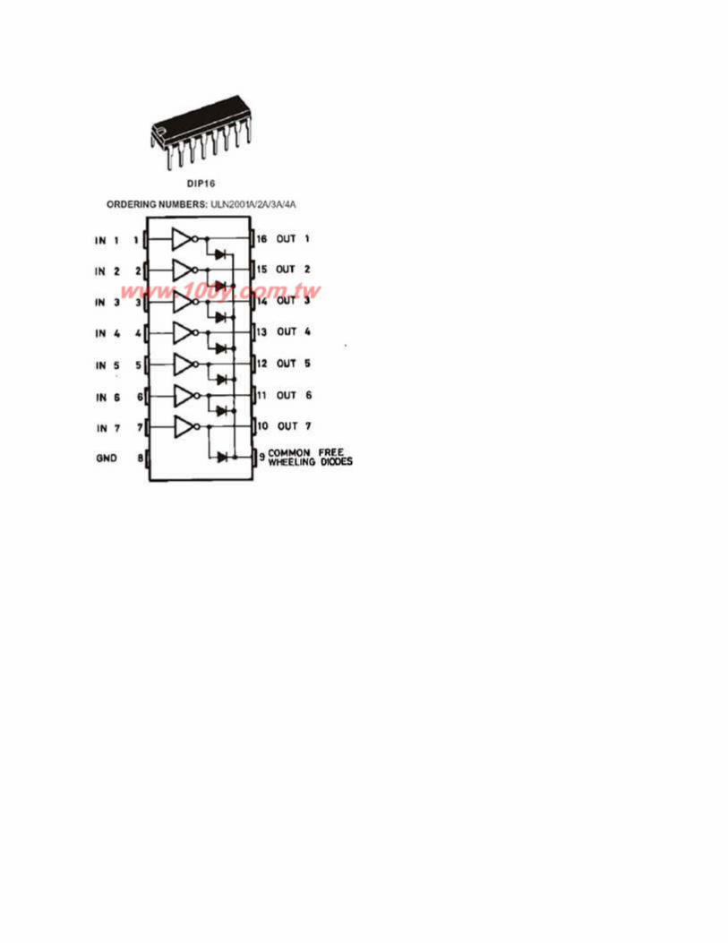
ULN2003A
The ULN2001A, ULN2002A, ULN2003 andULN2004Aare high voltage,high current Darlington arrays each containing seven open collector darling ton pairs with common emitters. Each channelrated at 500mAand can withstand peak currents of 600mA.Suppressiondiodesare included for inductive load driving and the inputs are pinned oppositethe outputs to simplify board layout.
L293D IC
The L293D is a quadruple push-pull 4 channel driver capable of delivering 600 mA (1.2 A peak surge) per channel. The L293D is ideal for controlling the forward/reverse/brake motions of small DC motors controlled by a microcontroller such as a PIC or BASIC Stamp.
The L293D is a high voltage, high current four channel driver designed to accept standard TTL logic levels and drive inductive loads (such as relays solenoids, DC and stepping motors) and switching power transistors. The L293D is suitable for use in switching applications at frequencies up to 5 KHz.
Features Include:
600 mA Output Current Capability Per Driver
Pulsed Current 1.2 A / Driver
Wide Supply Voltage Range: 4.5 V to 36 V
Separate Input-Logic Supply
NE Package Designed for Heat Sinking
Thermal Shutdown & Internal ESD Protection
High-Noise-Immunity Inputs
MEMS SENSOR
Micro-electromechanical systems (MEMS) are Free scale’s enabling technology for
acceleration and pressure sensors. MEMSbasedsensor products provide an
interfacethat can sense, process and/or control the surrounding environment. Free
scale’s MEMS technology provides the following advantages: cost efficiency, low power,
miniaturization, high performance andintegration. Functionality can be integrated onthe
same silicon or in the same package,which reduces the component count and
contributes to overall cost savings.
FLEX SENSORS
Images new bi-directional Bi-Flex Bend Sensor™ is a unique component that changes resistance when bent. An un-flexed sensor has a nominal resistance of 10,000 ohms
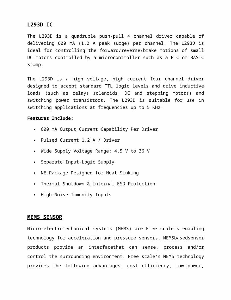
(10 K). As the flex sensor is bent in either direction the resistance gradually decreases. Sensor is also pressure sensitive, and may be used as a force or pressure sensorThe flex sensor operating temperature is -45F to 125F
.
FLEX SENSOR
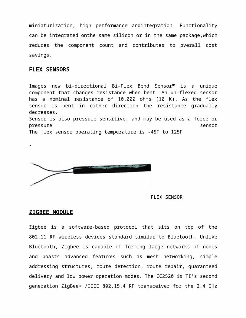
ZIGBEE MODULE
Zigbee is a software-based protocol that sits on top of the 802.11 RF wireless devices
standard similar to Bluetooth. Unlike Bluetooth, Zigbee is capable of forming large
networks of nodes and boasts advanced features such as mesh networking, simple
addressing structures, route detection, route repair, guaranteed delivery and low power
operation modes. The CC2520 is TI's second generation ZigBee® /IEEE 802.15.4 RF
transceiver for the 2.4 GHz unlicensed ISM band. This chip enables industrial grade
applications by offering state-of-the-art selectivity/co-existence, excellent link budget,
operation up to 125°C and low voltage operation.
Zigbee module
Wireless camera
Wireless camera is mainly used to control the device remotely. In order to transmit the
data using rf module. Thus by this we can control the vehicle by viewing the real time
video through the tv.
STEPPER MOTORS AND DC MOTOR
Stepper motors operate differently from DC brush motors, which rotate when voltage is
applied to their terminals. Stepper motors, on the other hand, effectively have multiple
"toothed" electromagnets arranged around a central gear-shaped piece of iron. The
electromagnets are energized by an external control circuit, such as a microcontroller.
To make the motor shaft turn, first, one electromagnet is given power, which makes the
gear's teeth magnetically attracted to the electromagnet's teeth. When the gear's teeth
are aligned to the first electromagnet, they are slightly offset from the next
electromagnet. So when the next electromagnet is turned on and the first is turned off,
the gear rotates slightly to align with the next one, and from there the process is
repeated. Each of those slight rotations is called a "step", with an integer of steps
making a full rotation. In that way, the motor can be turned by a precise angle. A DC
motor is an electric motor that runs on direct current (DC) electricity.
.Brushless DC motors use a rotating permanent
magnet or soft magnetic core in the rotor, and stationary electrical magnets on the
motor housing. A motor controller converts DC to AC. This design is simpler than that of
brushed motors because it eliminates the complication of transferring power from
outside the motor to the spinning rotor. Advantages of brushless motors include long life
span, little or no maintenance, and high efficiency. Disadvantages include high initial
cost, and more complicated motor speed controllers. Some such brushless motors are
sometimes referred to as "synchronous motors" although they have no external power
supply to be synchronized with, as would be the case with normal AC synchronous
motors.
PIC 16F873A
Microcontroller
ZigBee Module
MEMS Sensor
Accelerometer
Flex sensors
PROJECT DESCRIPTION
In this project there are two parts, Multi level hand gesture capture and a
Shooting Robot. The Robot is designed with microcontroller (PIC), Zigbee, Drive &
shooting Mechanisms Sensors laser point and wireless camera. In the hand gesture
captureside there are Microcontroller, accelerometer, flex sensor’s and Zigbee module.
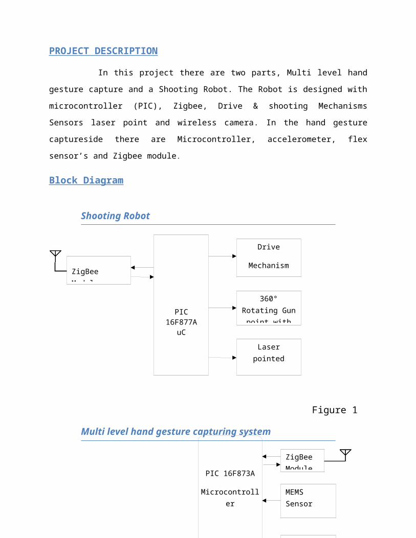
Block Diagram
Shooting Robot
Figure 1
Multi level hand gesture capturing system
Figure 2
PIC 16F877AuC
ZigBee Module
Drive
Mechanism
Laser pointed
Firing mechanism
360° Rotating Gun point with
tilt control
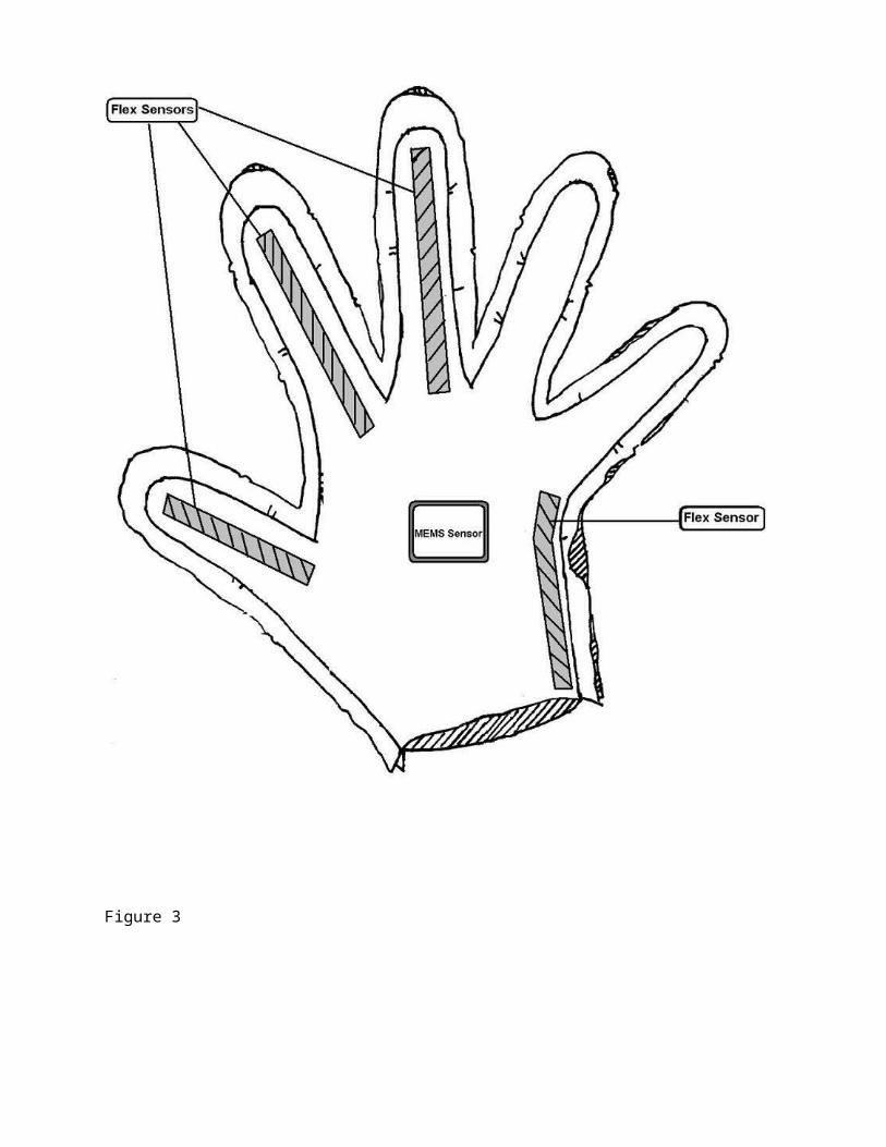
Multi level hand gesture capturing hand glove design
Figure 3

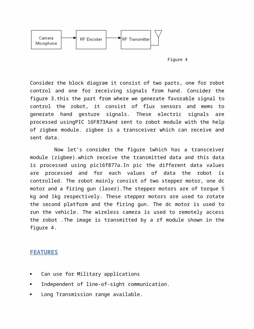
Figure 4
Consider the block diagram it consist of two parts, one for robot control and one for receiving signals from hand. Consider the figure 3.this the part from where we generate favorable signal to control the robot, it consist of flux sensors and mems to generate hand gesture signals. These electric signals are processed usingPIC 16F873Aand sent to robot module with the help of zigbee module. zigbee is a transceiver which can receive and sent data.
Now let’s consider the figure 1which has a transceiver module (zigbee).which receive the transmitted data and this data is processed using pic16f877a.In pic the different data values are processed and for each values of data the robot is controlled. The robot mainly consist of two stepper motor, one dc motor and a firing gun (laser).The stepper motors are of torque 5 kg and 1kg respectively. These stepper motors are used to rotate the second platform and the firing gun. The dc motor is used to run the vehicle. The wireless camera is used to remotely access the robot .The image is transmitted by a rf module shown in the figure 4.
FEATURES
Can use for Military applications
Independent of line-of-sight communication.
Long Transmission range available.
Low power consumption, with battery life.
Robot can control from Multi level hand gesture commands.
Highly reliable.
CIRCUIT DIAGRAM
U 6
P I C 1 6 F 8 7 3 / S O
M C L R / V P P / TH V1
R A 0 / A N 02
R A 1 / A N 13
R A 2 / A N 2 / V R E F -4
R A 3 / A N 3 / V R E F +5
R A 4 / T0 C K I6
R A 5 / S S / A N 47
GN
D8
O S C 1 / C L K I N9
O S C 2 / C L K O U T1 0
R C 0 / T1 O S O / T1 C K I1 1
R C 1 / T1 O S I / C C P 21 2
R C 2 / C C P 11 3
R C 3 / S C K / S C L1 4
R C 4 / S D I / S D A1 5
R C 5 / S D O1 6
R C 6 / TX/ C K1 7
R C 7 / R X/ D T1 8
GN
D19
VDD
20
R B 0 / I N T2 1R B 12 2R B 22 3R B 3 / P G M2 4R B 42 5R B 52 6R B 6 / P G C2 7R B 7 / P G D2 8
C 1 1
2 2 p F
C 1 2
2 2 p F
Y 22 0 M H z
R 1 2
1 k
D 2
L E D
U 5L M 3 1 7
V I N3
ADJ
1
V O U T2
J 8
Battery
1 2
R 1 4
1 k
R 1 3
1 0 k
C 50 . 1 u F
+ C 61 u F
V C C
V C C
R 1 5R
V C C
V C CV C C
J 1 4
ZigBee Module
1
23
4
5
6789 10
2 01 91 81 71 61 51 41 31 21 1
R 1 61 0 k
FLEX SensorJ 1 0
C O N 212
FLEX SensorJ 1 1
C O N 212
FLEX SensorJ 1 2
C O N 212
FLEX SensorJ 1 3
C O N 212
V C C
J 9
M M A 7 6 6 0
12345 6
7891 0C 8
0 . 1 u F+
C 7
1 0 u F
C 1 0
0 . 1 u F+
C 9
1 0 u F
V C CV C C
S D AS C L
S D AS C L
FIGURE: 2.CIRCUIT DIAGRAM OF HAND PART

J 2
S TE P P E R
12345
J 3
S TE P P E R
12345
V C C _ 1 2
V C C _ 1 2
I N 4
L A S E R
I N 3I N 2I N 1
J 5
M O TO R 1
12
R 1
1 k
J 6
M O TO R 2
12
D 1
L E D
C 3
2 2 p F
C 4
2 2 p F
Y 12 0 M H z
R 4 4 . 7 k
V C C
U 3
P I C 1 6 F 8 7 7 A
R A 0 / A N 02
R A 1 / A N 13
R A 2 / A N 2 / V R E F -/ C V R E F4
R A 3 / A N 3 / V R E F +5
R A 4 / T0 C K I / C 1 O U T6
R A 5 / A N 4 / S S / H L V D I N / C 2 O U T7
R A 6 / O S C 2 / C L K O1 4
R A 7 / O S C 1 / C L K I1 3
R B 0 / I N T0 / F L T0 / A N 1 23 3
R B 1 / I N T1 / A N 1 03 4
R B 2 / I N T2 / A N 83 5
R B 3 / A N 9 / C C P 23 6
R B 4 / K B I 0 / A N 1 13 7
R B 5 / K B I 1 / P G M3 8
R B 6 / K B I 2 / P G C3 9
R B 7 / K B I 3 / P G D4 0
R E 0 / R D / A N 58
R E 1 / W R / A N 69
R E 2 / C S / A N 71 0
R E 3 / M C L R / V P P1
VS
S12
VS
S31
R C 0 / T1 O S O / T1 3 C K I1 5
R C 1 / T1 O S I / C C P 21 6
R C 2 / C C P 1 / P 1 A1 7
R C 3 / S C K / S C L1 8
R C 4 / S D I / S D A2 3
R C 5 / S D O2 4
R C 6 / TX/ C K2 5
R C 7 / R X/ D T2 6
R D 0 / P S P 01 9
R D 1 / P S P 12 0
R D 2 / P S P 22 1
R D 3 / P S P 32 2
R D 4 / P S P 42 7
R D 5 / P S P 5 / P 1 B2 8
R D 6 / P S P 6 / P 1 C2 9
R D 7 / P S P 7 / P 1 D3 0
VD
D11
VD
D32
R 6
1 0 k
V C C V C C
J 4
ZigBee Module
1
23
4
5
6789 10
2 01 91 81 71 61 51 41 31 21 1
R 51 0 k
R 7
1 0 k
R 8
1 0 k
R 9
1 0 k
V C C
IN1
IN2
IN3
IN4
U 1L M 3 1 7
V I N3
AD
J1
V O U T2
J 1
Battery
1 2
V C C _ 1 2
R 3
1 k
R 2
1 0 k
C 10 . 1 u F
+ C 21 u F
V C C
U 4
L 2 9 3 D
I N 12
I N 27
I N 31 0
I N 41 5
E N 11
E N 29
O U T13
O U T26
O U T31 1
O U T41 4
GN
D4
GN
D5
GN
D13
GN
D12
V S S1 6
V S8
V C C
V C C _ 1 2
U 2
U L N 2 8 0 3
C O M1 0
GN
D9
I N 11
I N 22
I N 33
I N 44
I N 55
I N 66
I N 77
I N 88
O U T11 8
O U T21 7
O U T31 6
O U T41 5
O U T51 4
O U T61 3
O U T71 2
O U T81 1
V C C _ 1 2
S TE P 1 2S TE P 1 1
S TE P 1 4S TE P 1 3
S TE P 2 3S TE P 2 2S TE P 2 1
S TE P 2 4
S TE P 1 1S TE P 1 2
S TE P 2 2S TE P 2 3
S TE P 1 3S TE P 1 4
S TE P 2 4
S TE P 2 1
Q 1B C 1 0 7
3
2
1
R 1 1
1 K
R 1 01 0 K
V C C
L A S E R
J 7
L A S E R
12
FIGURE 2.1 . CIRCUIT DIAGRAM OF ROBOT PART
ALGORITHM
1. gesture capturing system wait for the start action
2. The robot waits for the command from the hand gesture capturing system.
3. After the START action, commands according to the hand gesture send to the
robot
4. When the robot receive the command, the robot follow the actions
5. Go to step 4.
6. Robot will STOP on the Power ON the Robot
7. Power ON hand gesture capturing system
8. Wireless Camera will transmit the data to system
9. Hand gesture capturing system start reading MEMS sensor
10.Hand gesture capturing system start reading FLEX sensor
11.Hand command from hand gesture capturing system
This is the main steps taking place in the robot function.


