5642 ⟨696⟩ Crystalline Solids / Physical Tests Second Supplement to USP 35–NF 30
each sample. The mean of these values is then calculated. Sample HandlingThe exact requirements will depend on the equipment ca-pability and degree of accuracy needed. The chemical and physical stability of solids may decrease
with decreasing crystallinity. In particular, solids of low crys-tallinity, especially amorphous solids, tend to sorb water va-Isoperibol Solution Calorimetry por from the atmosphere, leading to crystallization and acorresponding gain in crystallinity. For these reasons, anhy-In the isoperibol solution calorimeter, the heat change drous samples whose crystallinity is to be determined mustduring the solution process causes a corresponding change be stored at zero humidity or below critical humidity levelsin temperature of the solvent–solute system (i.e., solution). in sealed chambers containing a desiccant, preferably con-This temperature change is measured by a temperature sen- taining an indicator of effectiveness. If crystallinity–humiditysor, which is wired to an electrical circuit that records an studies are to be carried out, the sample is stored in aelectrical signal corresponding to the temperature change. sealed chamber containing a saturated salt solution to pro-Typically, this temperature change in an electronic form is vide a defined relative humidity.■2S (USP35)measured at precisely defined time intervals to produce
temperature–time data that are collected, analyzed by acomputer, and then plotted. A blank run without additionof the solid solute to the solvent normally shows no discern-ible change in the slope of the temperature–time plot.
For isoperibol solution calorimeters, response is fairlyrapid, but corrections must be made for any heat losses to ⟨711⟩ DISSOLUTIONor heat gains from the bath. Therefore, isoperibol solutioncalorimeters are more advantageous than isothermal solu-tion calorimeters when the solution process is relatively fast.For all measurements of enthalpy of solution using isoper- This general chapter is harmonized with the correspond-ibol solution calorimeters, the choice of solvent is critical. ing texts of the European Pharmacopoeia and/or the JapaneseThe nature and mass of the solvent and the mass of sample Pharmacopoeia. These pharmacopeias have undertaken notallow the total heat change, corresponding to total dissolu- to make any unilateral change to this harmonized chapter.tion of the solid, to proceed to completion within five min Portions of the present general chapter text that are na-under vigorous stirring at a constant rotational speed within tional USP text, and therefore not part of the harmonizedthe range of 400–600 revolutions/min. text, are marked with symbols (✦
✦) to specify this fact.The effective heat capacity of the calorimeter cell and its This test is provided to determine compliance with the
contents is determined for every calorimeter run. This deter- dissolution requirements ✦where stated in the individualmination is accomplished by electrical heating of the con- monograph✦ for dosage forms administered orally. In thistents of the calorimeter cell. The effective heat capacity is general chapter, a dosage unit is defined as 1 tablet or 1determined according to one of two protocols—either by capsule or the amount specified. ✦Of the types of apparatusmaking one determination after ampul breakage or by mak- described herein, use the one specified in the individualing one determination before and a second determination monograph. Where the label states that an article is enteric-after ampul breakage, and then averaging the two results. coated, and where a dissolution or disintegration test thatThe accuracy and reliability of the electrical heating are es- does not specifically state that it is to be applied to delayed-tablished by the accuracy and reliability of the aforemen- release articles is included in the individual monograph, thetioned chemical calibrations. procedure and interpretation given for Delayed-Release Dos-
age Forms is applied unless otherwise specified in the indi-vidual monograph. For hard or soft gelatin capsules and gel-Isothermal Solution Calorimetry atin-coated tablets that do not conform to the Dissolutionspecification, repeat the test as follows. Where water or aIn the isothermal (constant temperature) solution calorim- medium with a pH of less than 6.8 is specified as the Me-eter, the heat change during the solution process is com- dium in the individual monograph, the same Medium speci-pensated for by an equal but opposite energy change, such fied may be used with the addition of purified pepsin thatthat the temperature of the solvent–solute system (i.e., solu- results in an activity of 750,000 Units or less per 1000 mL.tion) remains essentially constant. This equal but opposite For media with a pH of 6.8 or greater, pancreatin can beenergy change is measured and, when its sign is reversed, added to produce not more than 1750 USP Units of prote-provides the enthalpy of solution. For isothermal calorime- ase activity per 1000 mL.ters, response is relatively slow, but the compensation pro-
cess eliminates the effects of heat losses to or heat gainsfrom the bath. Therefore, isothermal calorimeters are more Change to read:advantageous than isoperibol calorimetry when the solutionprocess is relatively slow. USP Reference Standards ⟨11⟩—•• (RB 1-Feb-2012) USP Pred-
nisone Tablets RS.✦
Solution Calorimeter CalibrationChange to read:
To ensure the accuracy of the calorimeter, chemical cali-brations must be performed on a regular basis. For an endo-thermic solution process, the calibration of the calorimeter ischecked by measuring the heat absorbed during the dissolu- APPARATUStion of potassium chloride in distilled water at 298.15 K(25.0°). The established enthalpy change in this endother-mic process is 235.5 J/g (17.56 kJ/mol). For an exothermic
Apparatus 1 (Basket Apparatus)solution process, the calorimeter is checked by measuringthe heat evolved during the dissolution of 5 g/L of
The assembly consists of the following: a vessel, whichtromethamine [tris(hydroxymethyl)aminomethane, THAM]may be covered, made of glass or other inert, transparentin a 0.1 mol/L aqueous hydrochloric acid solution at 298.15
K (25.0°). The established heat for the aforementioned pro-cess is −246.0 J/g (−29.80 kJ/mol).
Official from December 1, 2012Copyright (c) 2012 The United States Pharmacopeial Convention. All rights reserved.
Accessed from 128.83.63.20 by nEwp0rt1 on Tue Jun 05 03:46:33 EDT 2012
Second Supplement to USP 35–NF 30 Physical Tests / ⟨711⟩ Dissolution 5643
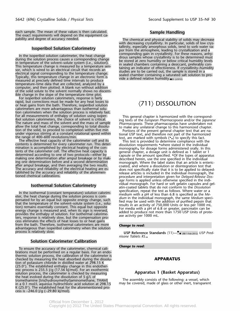
Figure 1. Basket stirring element.
material1; a motor; a metallic drive shaft; and a cylindrical that could affect the results. A speed-regulating device isbasket. The vessel is partially immersed in a suitable water used that allows the shaft rotation speed to be selected andbath of any convenient size or heated by a suitable device maintained at the specified rate ✦given in the individualsuch as a heating jacket. The water bath or heating device monograph✦ within ±4%.permits holding the temperature inside the vessel at Shaft and basket components of the stirring element are37 ± 0.5° during the test and keeping the bath fluid in con- fabricated of stainless steel, type 316, or other inert mate-stant, smooth motion. No part of the assembly, including rial, to the specifications shown in Figure 1. A basket havingthe environment in which the assembly is placed, contrib- a gold coating of about 0.0001 inch (2.5 µm) thick may beutes significant motion, agitation, or vibration beyond that used. A dosage unit is placed in a dry basket at the begin-due to the smoothly rotating stirring element. An apparatus ning of each test. The distance between the inside bottomthat permits observation of the specimen and stirring ele- of the vessel and the bottom of the basket is maintained atment during the test is preferable. The vessel is cylindrical, 25 ± 2 mm during the test.with a hemispherical bottom and ✦with one of the followingdimensions and capacities: for a nominal✦ capacity of 1 L,
Apparatus 2 (Paddle Apparatus)the height is 160 to 210 mm and its inside diameter is 98to 106 mm; ✦for a nominal capacity of 2 L, the height is
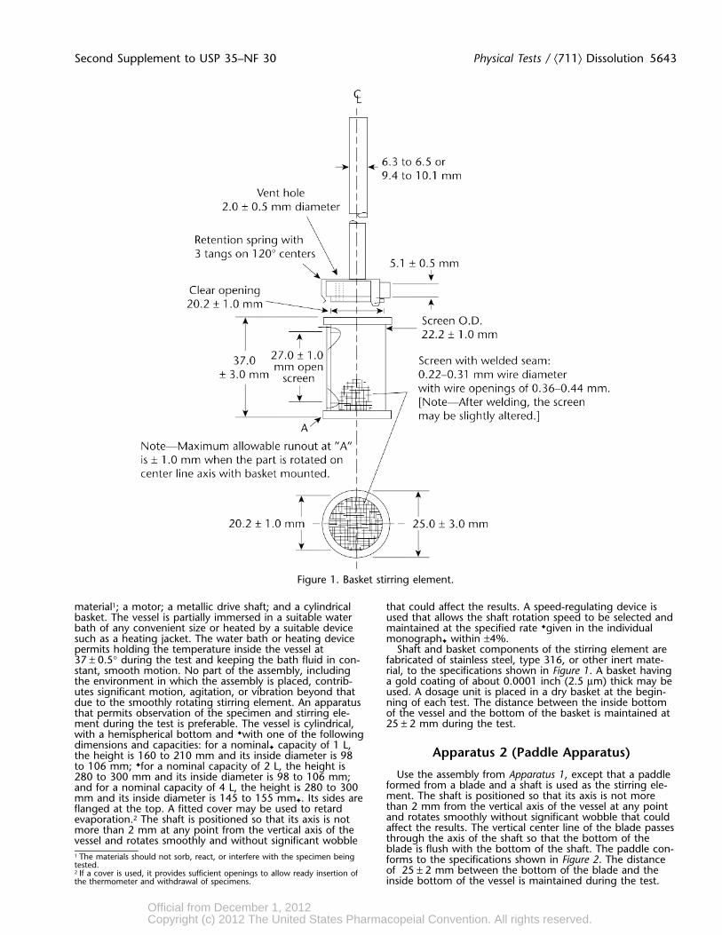
Use the assembly from Apparatus 1, except that a paddle280 to 300 mm and its inside diameter is 98 to 106 mm;formed from a blade and a shaft is used as the stirring ele-and for a nominal capacity of 4 L, the height is 280 to 300ment. The shaft is positioned so that its axis is not moremm and its inside diameter is 145 to 155 mm✦. Its sides arethan 2 mm from the vertical axis of the vessel at any pointflanged at the top. A fitted cover may be used to retardand rotates smoothly without significant wobble that couldevaporation.2 The shaft is positioned so that its axis is notaffect the results. The vertical center line of the blade passesmore than 2 mm at any point from the vertical axis of thethrough the axis of the shaft so that the bottom of thevessel and rotates smoothly and without significant wobbleblade is flush with the bottom of the shaft. The paddle con-
1 The materials should not sorb, react, or interfere with the specimen being forms to the specifications shown in Figure 2. The distancetested. of 25 ± 2 mm between the bottom of the blade and the2 If a cover is used, it provides sufficient openings to allow ready insertion ofthe thermometer and withdrawal of specimens. inside bottom of the vessel is maintained during the test.
Official from December 1, 2012Copyright (c) 2012 The United States Pharmacopeial Convention. All rights reserved.
Accessed from 128.83.63.20 by nEwp0rt1 on Tue Jun 05 03:46:33 EDT 2012
5644 ⟨711⟩ Dissolution / Physical Tests Second Supplement to USP 35–NF 30
The metallic or suitably inert, rigid blade and shaft comprise and screens that are made of suitable nonsorbing anda single entity. A suitable two-part detachable design may nonreactive material and that are designed to fit the topsbe used provided the assembly remains firmly engaged dur- and bottoms of the reciprocating cylinders; and a motoring the test. The paddle blade and shaft may be coated and drive assembly to reciprocate the cylinders vertically in-with a suitable coating so as to make them inert. The dos- side the vessels and, if desired, index the reciprocating cylin-age unit is allowed to sink to the bottom of the vessel ders horizontally to a different row of vessels. The vessels arebefore rotation of the blade is started. A small, loose piece partially immersed in a suitable water bath of any conven-of nonreactive material, such as not more than a few turns ient size that permits holding the temperature at 37 ± 0.5°of wire helix, may be attached to dosage units that would during the test. No part of the assembly, including the envi-otherwise float. An alternative sinker device is shown in Fig- ronment in which the assembly is placed, contributes signifi-ure 2a. Other validated sinker devices may be used. cant motion, agitation, or vibration beyond that due to the
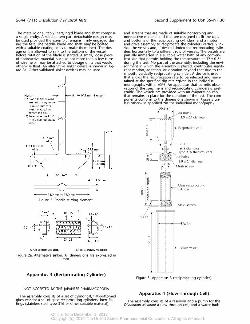
smooth, vertically reciprocating cylinder. A device is usedthat allows the reciprocation rate to be selected and main-tained at the specified dip rate ✦given in the individualmonograph✦ within ±5%. An apparatus that permits obser-vation of the specimens and reciprocating cylinders is pref-erable. The vessels are provided with an evaporation capthat remains in place for the duration of the test. The com-ponents conform to the dimensions shown in Figure 3 un-less otherwise specified ✦in the individual monograph✦.
Figure 2. Paddle stirring element.
Figure 2a. Alternative sinker. All dimensions are expressed inmm.
Apparatus 3 (Reciprocating Cylinder)Figure 3. Apparatus 3 (reciprocating cylinder).
NOT ACCEPTED BY THE JAPANESE PHARMACOPOEIAApparatus 4 (Flow-Through Cell)
The assembly consists of a set of cylindrical, flat-bottomedglass vessels; a set of glass reciprocating cylinders; inert fit- The assembly consists of a reservoir and a pump for thetings (stainless steel type 316 or other suitable material), Dissolution Medium; a flow-through cell; and a water bath
Official from December 1, 2012Copyright (c) 2012 The United States Pharmacopeial Convention. All rights reserved.
Accessed from 128.83.63.20 by nEwp0rt1 on Tue Jun 05 03:46:33 EDT 2012
Second Supplement to USP 35–NF 30 Physical Tests / ⟨711⟩ Dissolution 5645
that maintains the Dissolution Medium at 37 ± 0.5°. Use thespecified cell size ✦as given in the individual monograph✦.
The pump forces the Dissolution Medium upwards throughthe flow-through cell. The pump has a delivery range be-tween 240 and 960 mL per hour, with standard flow ratesof 4, 8, and 16 mL per minute. It must deliver a constantflow (±5% of the nominal flow rate); the flow profile is si-nusoidal with a pulsation of 120 ± 10 pulses per minute. Apump without pulsation may also be used. Dissolution testprocedures using a flow-through cell must be characterizedwith respect to rate and any pulsation.
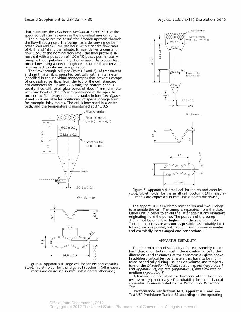
The flow-through cell (see Figures 4 and 5), of transparentand inert material, is mounted vertically with a filter system(specified in the individual monograph) that prevents escapeof undissolved particles from the top of the cell; standardcell diameters are 12 and 22.6 mm; the bottom cone isusually filled with small glass beads of about 1-mm diameterwith one bead of about 5 mm positioned at the apex toprotect the fluid entry tube; and a tablet holder (see Figures4 and 5) is available for positioning of special dosage forms,for example, inlay tablets. The cell is immersed in a waterbath, and the temperature is maintained at 37 ± 0.5°.
Figure 5. Apparatus 4, small cell for tablets and capsules(top), tablet holder for the small cell (bottom). (All measure-
ments are expressed in mm unless noted otherwise.)
The apparatus uses a clamp mechanism and two O-ringsto assemble the cell. The pump is separated from the disso-lution unit in order to shield the latter against any vibrationsoriginating from the pump. The position of the pumpshould not be on a level higher than the reservoir flasks.Tube connections are as short as possible. Use suitably inerttubing, such as polytef, with about 1.6-mm inner diameterand chemically inert flanged-end connections.
APPARATUS SUITABILITY
The determination of suitability of a test assembly to per-form dissolution testing must include conformance to thedimensions and tolerances of the apparatus as given above.In addition, critical test parameters that have to be moni-tored periodically during use include volume and tempera-Figure 4. Apparatus 4, large cell for tablets and capsules ture of the Dissolution Medium, rotation speed (Apparatus 1(top), tablet holder for the large cell (bottom). (All measure- and Apparatus 2), dip rate (Apparatus 3), and flow rate ofments are expressed in mm unless noted otherwise.) medium (Apparatus 4).
Determine the acceptable performance of the dissolutiontest assembly periodically. ✦The suitability for the individualapparatus is demonstrated by the Performance VerificationTest.
Performance Verification Test, Apparatus 1 and 2—Test USP Prednisone Tablets RS according to the operating
Official from December 1, 2012Copyright (c) 2012 The United States Pharmacopeial Convention. All rights reserved.
Accessed from 128.83.63.20 by nEwp0rt1 on Tue Jun 05 03:46:33 EDT 2012
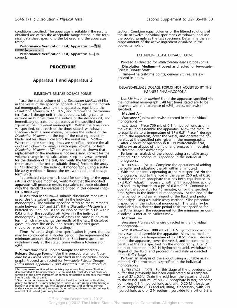
5646 ⟨711⟩ Dissolution / Physical Tests Second Supplement to USP 35–NF 30
conditions specified. The apparatus is suitable if the results section. Combine equal volumes of the filtered solutions ofobtained are within the acceptable range stated in the tech- the six or twelve individual specimens withdrawn, and usenical data sheet specific to the lot used and the apparatus the pooled sample as the test specimen. Determine the av-tested. erage amount of the active ingredient dissolved in the
pooled sample.✦Performance Verification Test, Apparatus 3—•[Tocome.]• (RB 1-Feb-2012)
Performance Verification Test, Apparatus 4—[To EXTENDED-RELEASE DOSAGE FORMScome.]✦
Proceed as directed for Immediate-Release Dosage Forms.Dissolution Medium—Proceed as directed for Immediate-PROCEDURE
Release Dosage Forms.Time—The test-time points, generally three, are ex-
pressed in hours.Apparatus 1 and Apparatus 2
DELAYED-RELEASE DOSAGE FORMS NOT ACCEPTED BY THEJAPANESE PHARMACOPOEIAIMMEDIATE-RELEASE DOSAGE FORMS
Use Method A or Method B and the apparatus specified ✦inPlace the stated volume of the Dissolution Medium (±1%) the individual monograph✦. All test times stated are to bein the vessel of the specified apparatus ✦given in the individ- observed within a tolerance of ±2%, unless otherwiseual monograph✦, assemble the apparatus, equilibrate the specified.Dissolution Medium to 37 ± 0.5°, and remove the thermome-Method A—ter. Place 1 dosage unit in the apparatus, taking care toProcedure ✦(unless otherwise directed in the individualexclude air bubbles from the surface of the dosage unit, and
monograph)✦—immediately operate the apparatus at the specified rate✦given in the individual monograph✦. Within the time inter- ACID STAGE—Place 750 mL of 0.1 N hydrochloric acid inval specified, or at each of the times stated, withdraw a the vessel, and assemble the apparatus. Allow the mediumspecimen from a zone midway between the surface of the to equilibrate to a temperature of 37 ± 0.5°. Place 1 dosageDissolution Medium and the top of the rotating basket or unit in the apparatus, cover the vessel, and operate the ap-blade, not less than 1 cm from the vessel wall. [NOTE— paratus at the specified rate ✦given in the monograph✦.Where multiple sampling times are specified, replace the ali- After 2 hours of operation in 0.1 N hydrochloric acid,quots withdrawn for analysis with equal volumes of fresh withdraw an aliquot of the fluid, and proceed immediatelyDissolution Medium at 37° or, where it can be shown that as directed under Buffer Stage.replacement of the medium is not necessary, correct for the Perform an analysis of the aliquot using a suitable assayvolume change in the calculation. Keep the vessel covered method. ✦The procedure is specified in the individualfor the duration of the test, and verify the temperature of monograph.✦
the mixture under test at suitable times.] Perform the analy- BUFFER STAGE—[NOTE—Complete the operations of addingsis ✦as directed in the individual monograph✦ using a suita- the buffer and adjusting the pH within 5 minutes.]ble assay method.3 Repeat the test with additional dosage With the apparatus operating at the rate specified ✦in theform units. monograph✦, add to the fluid in the vessel 250 mL of 0.20
If automated equipment is used for sampling or the appa- M tribasic sodium phosphate that has been equilibrated toratus is otherwise modified, verification that the modified 37 ± 0.5°. Adjust, if necessary, with 2 N hydrochloric acid orapparatus will produce results equivalent to those obtained 2 N sodium hydroxide to a pH of 6.8 ± 0.05. Continue towith the standard apparatus described in this general chap- operate the apparatus for 45 minutes, or for the specifiedter is necessary. time ✦given in the individual monograph✦. At the end of the
Dissolution Medium—A suitable dissolution medium is time period, withdraw an aliquot of the fluid, and performused. Use the solvent specified ✦in the individual the analysis using a suitable assay method. ✦The proceduremonograph✦. The volume specified refers to measurements is specified in the individual monograph. The test may bemade between 20° and 25°. If the Dissolution Medium is a concluded in a shorter time period than that specified forbuffered solution, adjust the solution so that its pH is within the Buffer Stage if the requirement for the minimum amount0.05 unit of the specified pH ✦given in the individual dissolved is met at an earlier time.✦
monograph✦. [NOTE—Dissolved gases can cause bubbles to Method B—form, which may change the results of the test. If dissolved Procedure ✦(unless otherwise directed in the individualgases influence the dissolution results, dissolved gases monograph)✦—should be removed prior to testing.4]
ACID STAGE—Place 1000 mL of 0.1 N hydrochloric acid inTime—Where a single time specification is given, the test the vessel, and assemble the apparatus. Allow the mediummay be concluded in a shorter period if the requirement for to equilibrate to a temperature of 37 ± 0.5°. Place 1 dosageminimum amount dissolved is met. Specimens are to be unit in the apparatus, cover the vessel, and operate the ap-withdrawn only at the stated times within a tolerance of paratus at the rate specified ✦in the monograph✦. After 2±2%. hours of operation in 0.1 N hydrochloric acid, withdraw an✦Procedure for a Pooled Sample for Immediate- aliquot of the fluid, and proceed immediately as directed
Release Dosage Forms—Use this procedure where Proce- under Buffer Stage.dure for a Pooled Sample is specified in the individual mono- Perform an analysis of the aliquot using a suitable assaygraph. Proceed as directed for Immediate-Release Dosage method. ✦The procedure is specified in the individualForms under Apparatus 1 and Apparatus 2 in the Procedure monograph.✦
3 Test specimens are filtered immediately upon sampling unless filtration is BUFFER STAGE—[NOTE—For this stage of the procedure, usedemonstrated to be unnecessary. Use an inert filter that does not cause ad- buffer that previously has been equilibrated to a tempera-sorption of the active ingredient or contain extractable substances that would ture of 37 ± 0.5°.] Drain the acid from the vessel, and addinterfere with the analysis.4 One method of deaeration is as follows: Heat the medium, while stirring to the vessel 1000 mL of pH 6.8 phosphate buffer, preparedgently, to about 41°, immediately filter under vacuum using a filter having a by mixing 0.1 N hydrochloric acid with 0.20 M tribasic so-porosity of 0.45 µm or less, with vigorous stirring, and continue stirring dium phosphate (3:1) and adjusting, if necessary, with 2 Nunder vacuum for about 5 minutes. Other validated deaeration techniques for
hydrochloric acid or 2 N sodium hydroxide to a pH of 6.8 ±removal of dissolved gases may be used.
Official from December 1, 2012Copyright (c) 2012 The United States Pharmacopeial Convention. All rights reserved.
Accessed from 128.83.63.20 by nEwp0rt1 on Tue Jun 05 03:46:33 EDT 2012

Second Supplement to USP 35–NF 30 Physical Tests / ⟨711⟩ Dissolution 5647
0.05. [NOTE—This may also be accomplished by removing the filter head, and fix the parts together by means of afrom the apparatus the vessel containing the acid and re- suitable clamping device. Introduce by the pump the Disso-placing it with another vessel containing the buffer and lution Medium warmed to 37 ± 0.5° through the bottom oftransferring the dosage unit to the vessel containing the the cell to obtain the flow rate specified ✦in the individualbuffer.] monograph✦ and measured with an accuracy of 5%. Collect
Continue to operate the apparatus for 45 minutes, or for the eluate by fractions at each of the times stated. Performthe specified time ✦given in the individual monograph✦. At the analysis as directed ✦in the individual monograph✦. Re-the end of the time period, withdraw an aliquot of the fluid, peat the test with additional dosage-form units.and perform the analysis using a suitable assay method. Dissolution Medium—Proceed as directed for Immediate-✦The procedure is specified in the individual monograph. Release Dosage Forms under Apparatus 1 and Apparatus 2.The test may be concluded in a shorter time period than Time—Proceed as directed for Immediate-Release Dosagethat specified for the Buffer Stage if the requirement for min- Forms under Apparatus 1 and Apparatus 2.imum amount dissolved is met at an earlier time.✦
EXTENDED-RELEASE DOSAGE FORMSApparatus 3 (Reciprocating Cylinder)Proceed as directed for Immediate-Release Dosage Forms
under Apparatus 4.Dissolution Medium—Proceed as directed for Immediate-NOT ACCEPTED BY THE JAPANESE PHARMACOPOEIA
Release Dosage Forms under Apparatus 4.IMMEDIATE-RELEASE DOSAGE FORMSTime—Proceed as directed for Immediate-Release Dosage
Forms under Apparatus 4.Place the stated volume of the Dissolution Medium in eachvessel of the apparatus, assemble the apparatus, equilibratethe Dissolution Medium to 37 ± 0.5°, and remove the ther-
DELAYED-RELEASE DOSAGE FORMSmometer. Place 1 dosage-form unit in each of the six recip-rocating cylinders, taking care to exclude air bubbles from
Proceed as directed for Delayed-Release Dosage Formsthe surface of each dosage unit, and immediately operateunder Apparatus 1 and Apparatus 2, using the specifiedthe apparatus as specified ✦in the individual monograph✦.media.During the upward and downward stroke, the reciprocating
Time—Proceed as directed for Delayed-Release Dosagecylinder moves through a total distance of 9.9 to 10.1 cm.Forms under Apparatus 1 and Apparatus 2.Within the time interval specified, or at each of the times
stated, raise the reciprocating cylinders and withdraw a por-tion of the solution under test from a zone midway between INTERPRETATIONthe surface of the Dissolution Medium and the bottom ofeach vessel. Perform the analysis as directed ✦in the individ-ual monograph✦. If necessary, repeat the test with addi-tional dosage-form units. Immediate-Release Dosage Forms
Dissolution Medium—Proceed as directed for Immediate-Release Dosage Forms under Apparatus 1 and Apparatus 2. Unless otherwise specified ✦in the individual monograph✦,
Time—Proceed as directed for Immediate-Release Dosage the requirements are met if the quantities of active ingredi-Forms under Apparatus 1 and Apparatus 2. ent dissolved from the dosage units tested conform to Ac-
ceptance Table 1. Continue testing through the three stagesunless the results conform at either S1 or S2. The quantity,
EXTENDED-RELEASE DOSAGE FORMS Q, is the amount of dissolved active ingredient ✦specified inthe individual monograph✦, expressed as a percentage of
Proceed as directed for Immediate-Release Dosage Forms the labeled content of the dosage unit; the 5%, 15%, andunder Apparatus 3. 25% values in Acceptance Table 1 are percentages of the
Dissolution Medium—Proceed as directed for Extended- labeled content so that these values and Q are in the sameRelease Dosage Forms under Apparatus 1 and Apparatus 2. terms.
Time—Proceed as directed for Extended-Release DosageForms under Apparatus 1 and Apparatus 2. Acceptance Table 1
NumberStage Tested Acceptance CriteriaDELAYED-RELEASE DOSAGE FORMS
S1 6 Each unit is not less than Q + 5%.Proceed as directed for Delayed-Release Dosage Forms, Average of 12 units (S1 + S2) is equal to or
Method B under Apparatus 1 and Apparatus 2 using one row greater than Q, and no unit is less than Qof vessels for the acid stage media and the following row of S2 6 − 15%.vessels for the buffer stage media and using the volume of Average of 24 units (S1 + S2 +S3) is equal tomedium specified (usually 300 mL). or greater than Q, not more than 2 units
Time—Proceed as directed for Immediate-Release Dosage are less than Q − 15%, and no unit is lessForms under Apparatus 1 and Apparatus 2. S3 12 than Q − 25%.
✦Immediate-Release Dosage Forms Pooled Sample—Apparatus 4 (Flow-Through Cell) Unless otherwise specified in the individual monograph, therequirements are met if the quantities of active ingredientdissolved from the pooled sample conform to the accompa-nying Acceptance Table for a Pooled Sample. Continue testingIMMEDIATE-RELEASE DOSAGE FORMS through the three stages unless the results conform at eitherS1 or S2. The quantity, Q, is the amount of dissolved activePlace the glass beads into the cell specified ✦in the ingredient specified in the individual monograph, expressedmonograph✦. Place 1 dosage unit on top of the beads or, if as a percentage of the labeled content.specified ✦in the monograph✦, on a wire carrier. Assemble
Official from December 1, 2012Copyright (c) 2012 The United States Pharmacopeial Convention. All rights reserved.
Accessed from 128.83.63.20 by nEwp0rt1 on Tue Jun 05 03:46:33 EDT 2012
5648 ⟨711⟩ Dissolution / Physical Tests Second Supplement to USP 35–NF 30
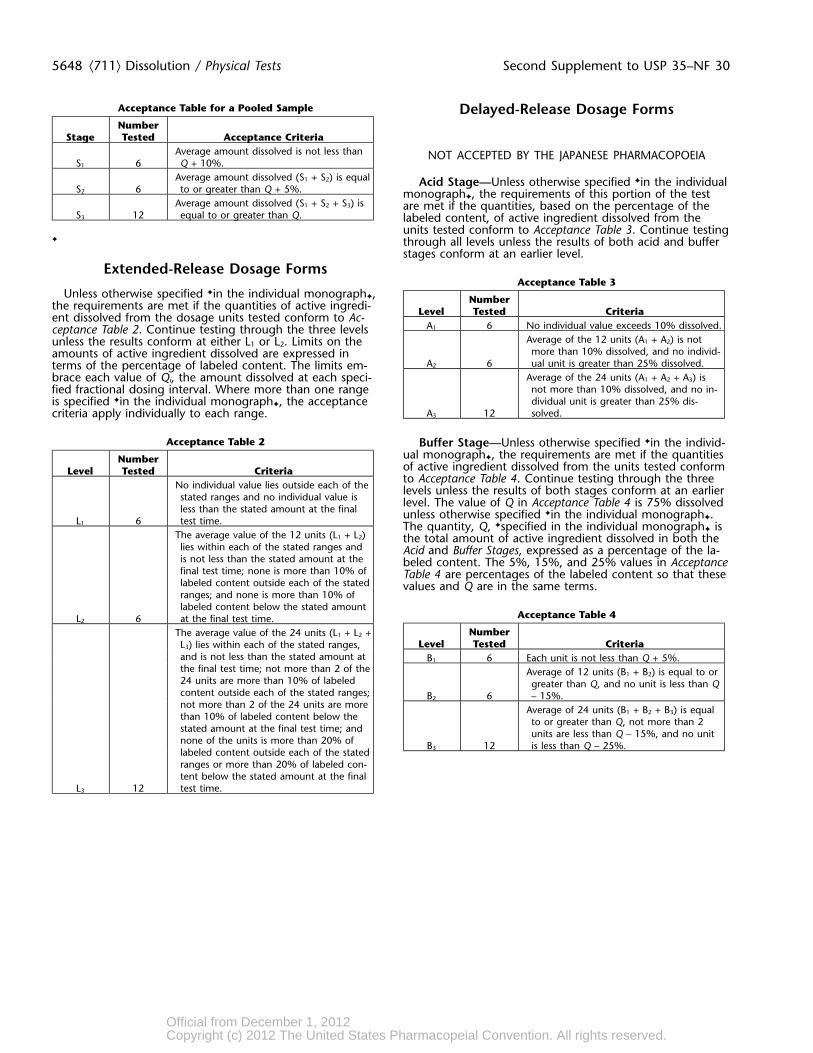
Acceptance Table for a Pooled Sample Delayed-Release Dosage FormsNumber
Stage Tested Acceptance CriteriaAverage amount dissolved is not less than NOT ACCEPTED BY THE JAPANESE PHARMACOPOEIA
S1 6 Q + 10%.Average amount dissolved (S1 + S2) is equal Acid Stage—Unless otherwise specified ✦in the individual
S2 6 to or greater than Q + 5%. monograph✦, the requirements of this portion of the testAverage amount dissolved (S1 + S2 + S3) is are met if the quantities, based on the percentage of the
S3 12 equal to or greater than Q. labeled content, of active ingredient dissolved from theunits tested conform to Acceptance Table 3. Continue testing
✦ through all levels unless the results of both acid and bufferstages conform at an earlier level.
Extended-Release Dosage FormsAcceptance Table 3
Unless otherwise specified ✦in the individual monograph✦, Numberthe requirements are met if the quantities of active ingredi- Level Tested Criteriaent dissolved from the dosage units tested conform to Ac-A1 6 No individual value exceeds 10% dissolved.ceptance Table 2. Continue testing through the three levels
Average of the 12 units (A1 + A2) is notunless the results conform at either L1 or L2. Limits on themore than 10% dissolved, and no individ-amounts of active ingredient dissolved are expressed in
A2 6 ual unit is greater than 25% dissolved.terms of the percentage of labeled content. The limits em-Average of the 24 units (A1 + A2 + A3) isbrace each value of Qi, the amount dissolved at each speci-not more than 10% dissolved, and no in-fied fractional dosing interval. Where more than one rangedividual unit is greater than 25% dis-is specified ✦in the individual monograph✦, the acceptance
A3 12 solved.criteria apply individually to each range.
Acceptance Table 2 Buffer Stage—Unless otherwise specified ✦in the individ-ual monograph✦, the requirements are met if the quantitiesNumberof active ingredient dissolved from the units tested conformLevel Tested Criteriato Acceptance Table 4. Continue testing through the three
No individual value lies outside each of the levels unless the results of both stages conform at an earlierstated ranges and no individual value is level. The value of Q in Acceptance Table 4 is 75% dissolvedless than the stated amount at the final unless otherwise specified ✦in the individual monograph✦.
L1 6 test time. The quantity, Q, ✦specified in the individual monograph✦ isThe average value of the 12 units (L1 + L2) the total amount of active ingredient dissolved in both thelies within each of the stated ranges and Acid and Buffer Stages, expressed as a percentage of the la-is not less than the stated amount at the beled content. The 5%, 15%, and 25% values in Acceptancefinal test time; none is more than 10% of Table 4 are percentages of the labeled content so that theselabeled content outside each of the stated values and Q are in the same terms.ranges; and none is more than 10% oflabeled content below the stated amount
Acceptance Table 4L2 6 at the final test time.NumberThe average value of the 24 units (L1 + L2 +
Level Tested CriteriaL3) lies within each of the stated ranges,and is not less than the stated amount at B1 6 Each unit is not less than Q + 5%.the final test time; not more than 2 of the Average of 12 units (B1 + B2) is equal to or24 units are more than 10% of labeled greater than Q, and no unit is less than Qcontent outside each of the stated ranges; B2 6 – 15%.not more than 2 of the 24 units are more Average of 24 units (B1 + B2 + B3) is equalthan 10% of labeled content below the to or greater than Q, not more than 2stated amount at the final test time; and units are less than Q – 15%, and no unitnone of the units is more than 20% of B3 12 is less than Q – 25%.labeled content outside each of the statedranges or more than 20% of labeled con-tent below the stated amount at the final
L3 12 test time.
Official from December 1, 2012Copyright (c) 2012 The United States Pharmacopeial Convention. All rights reserved.
Accessed from 128.83.63.20 by nEwp0rt1 on Tue Jun 05 03:46:33 EDT 2012
Second Supplement to USP 35–NF 30 Physical Tests / ⟨911⟩ Viscosity 5649
pendent of the shearing stress rate or rate of shear. UnlessChange to read:otherwise directed in the individual monograph, use MethodI.
.
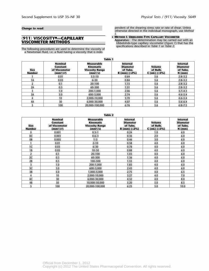
• METHOD I. UBBELOHDE-TYPE CAPILLARY VISCOMETER⟨911⟩ VISCOSITY■—CAPILLARY Apparatus: The determination may be carried out with anVISCOMETER METHODS Ubbelohde-type capillary viscometer (Figure 1) that has thespecifications described in Table 1 or Table 2.
The following procedures are used to determine the viscosity ofa Newtonian fluid, i.e. a fluid having a viscosity that is inde-
Table 1
Nominal Measurable Internal InternalConstant Kinematic Diameter Volume Diameter
Size of Viscometer Viscosity Range of Tube, of Bulb, of Tube,Number (mm2/s2) (mm2/s) R (mm) (±2%) C (mL) (±5%) N (mm)
1 0.01 3.5–10 0.64 5.6 2.8–3.21A 0.03 6–30 0.84 5.6 2.8–3.22 0.1 20–100 1.15 5.6 2.8–3.2
2A 0.3 60–300 1.51 5.6 2.8–3.23 1.0 200–1,000 2.06 5.6 3.7–4.3
3A 3.0 600–3,000 2.74 5.6 4.6–5.44 10 2,000–10,000 3.70 5.6 4.6–5.4
4A 30 6,000–30,000 4.07 5.6 5.6–6.45 100 20,000–100,000 6.76 5.6 6.8–7.5
Table 2
Nominal Measurable Internal InternalConstant Kinematic Diameter Volume Diameter
Size of Viscometer Viscosity Range of Tube, of Bulb, of Tube,Number (mm2/s2) (mm2/s) R (mm) (±2%) C (mL) (±5%) N (mm)
0 0.001 0.3–1 0.24 1.0 6.00C 0.003 0.6–3 0.36 2.0 6.00B 0.005 1–5 0.46 3.0 6.01 0.01 2–10 0.58 4.0 6.0
1C 0.03 6–30 0.78 4.0 6.01B 0.05 10–50 0.88 4.0 6.02 0.1 20–100 1.03 4.0 6.0
2C 0.3 60–300 1.36 4.0 6.02B 0.5 100–500 1.55 4.0 6.03 1.0 200–1,000 1.83 4.0 6.0
3C 3.0 600–3,000 2.43 4.0 6.03B 5.0 1,000–5,000 2.75 4.0 6.54 10 2,000–10,000 3.27 4.0 7.0
4C 30 6,000–30,000 4.32 4.0 8.04B 50 10,000–50,000 5.20 5.0 8.55 100 20,000–100,000 6.25 5.0 10.0
Official from December 1, 2012Copyright (c) 2012 The United States Pharmacopeial Convention. All rights reserved.
Accessed from 128.83.63.20 by nEwp0rt1 on Tue Jun 05 03:46:33 EDT 2012


