Sine-Cosine Interface Box for ComNav 1000, 2000 & 14xx Series Autopilots and
SI-TEX SP-70 & SP-80 Autopilots
Installation Instructions
PN 29030044 V1.0
ComNav Sine-Cosine Interface Box Installation Instructions
Document PN 29030044 V1.0 - 1 -
Welcome Thank you for purchasing a ComNav Marine Sine-Cosine Interface Box!
At ComNav, we are dedicated to reliability & quality in all our products, and proud of our prominence as a leader in the design and manufacture of marine autopilot systems. We promise to do our best to ensure your satisfaction with all your ComNav products.
ComNav Marine Ltd.
General Notice This document, ComNav part number 29030044 Version 1 Revision 0, contains the approved Installation Instructions for the Sine-Cosine Interface Box. Where versions of this document exist in other languages, the English version shall be considered authoritative.
Document History
Revision Date By Description
1R0 06 August 2004 FW First release 1R1 14 November 2008 FW, DTO • Added info for K-INT4, Vector G2/G2B and 14xx/SP-70/80
• Formatted with current template
ComNav Sine-Cosine Interface Box Installation Instructions
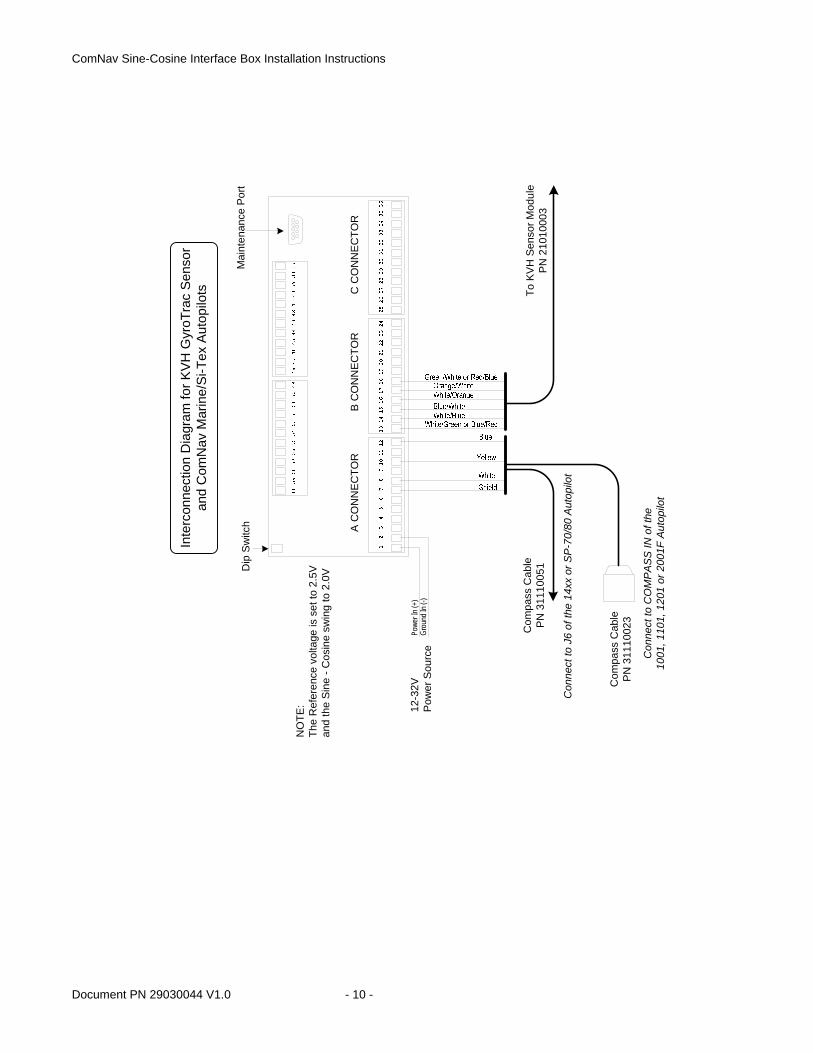
Introduction These Installation Instructions are for the ComNav Sine-Cosine Interface Box, PN 21010004. This document is mainly intended to describe how to connect and configure the current generation of the Interface Box (the K-INT 4) when a ComNav Vector G2/G2B GPS Compass is used for the Heading source of certain ComNav & SI-TEX Autopilot Systems. However, it also includes some historical wiring information, for the two previous generations of the Interface Box (Types K-INT 3 & K-INT 2), and for the KVH GyroTrac Sensor (PN 21010003).
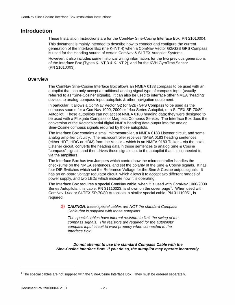
Overview The ComNav Sine-Cosine Interface Box allows an NMEA 0183 compass to be used with an autopilot that can only accept a traditional analog-signal type of compass input (usually referred to as “Sine-Cosine” signals). It can also be used to interface other NMEA “heading” devices to analog-compass-input autopilots & other navigation equipment. In particular, it allows a ComNav Vector G2 (or G2B) GPS Compass to be used as the compass source for a ComNav 1000, 2000 or 14xx Series Autopilot, or a SI-TEX SP-70/80 Autopilot. Those autopilots can not accept NMEA 0183 heading data; they were designed to be used with a Fluxgate Compass or Magnetic Compass Sensor. The Interface Box does the conversion of the Vector’s serial digital NMEA heading data output into the analog Sine-Cosine compass signals required by those autopilots. The Interface Box contains a small microcontroller, a NMEA 0183 Listener circuit, and some analog amplifier circuitry. The microcontroller receives NMEA 0183 heading sentences (either HDT, HDG or HDM) from the Vector – which is an NMEA 0183 Talker – via the box’s Listener circuit, converts the heading data in those sentences to analog Sine & Cosine “compass” signals, and then drives those signals out to the autopilot that it is connected to, via the amplifiers. The Interface Box has two Jumpers which control how the microcontroller handles the checksums on the NMEA sentences, and set the polarity of the Sine & Cosine signals. It has four DIP Switches which set the Reference Voltage for the Sine & Cosine output signals. It has an on-board voltage regulator circuit, which allows it to accept two different ranges of power supply, and two LEDs which indicate how it is operating. The Interface Box requires a special ComNav cable, when it is used with ComNav 1000/2000 Series Autopilots; this cable, PN 31110023, is shown on the cover page1. When used with ComNav 14xx or SI-TEX SP-70/80 Autopilots, a similar special cable, PN 31110051, is required.
CAUTION: these special cables are NOT the standard Compass Cable that is supplied with those autopilots.
The special cables have internal resistors to limit the swing of the compass signals. The resistors are required for the autopilots’ compass input circuit to work properly when connected to the Interface Box.
Do not attempt to use the standard Compass Cable with the Sine-Cosine Interface Box! If you do so, the autopilot may operate incorrectly.
1 The special cables are not supplied with the Sine-Cosine Interface Box. They must be ordered separately.
Document PN 29030044 V1.0 - 2 -
ComNav Sine-Cosine Interface Box Installation Instructions
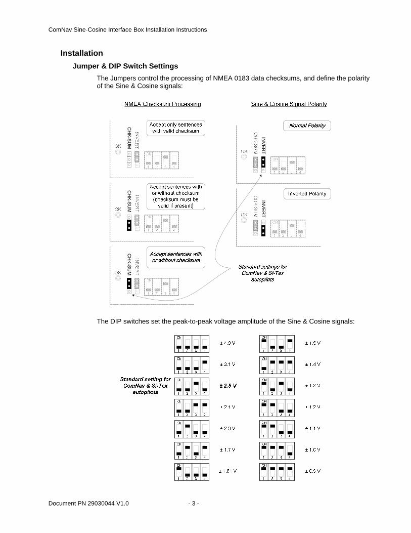
Installation Jumper & DIP Switch Settings
The Jumpers control the processing of NMEA 0183 data checksums, and define the polarity of the Sine & Cosine signals:
CH
K-S
UM
CH
K-S
UM
CH
K-S
UM
INV
ER
TIN
VE
RT
The DIP switches set the peak-to-peak voltage amplitude of the Sine & Cosine signals:
Document PN 29030044 V1.0 - 3 -
ComNav Sine-Cosine Interface Box Installation Instructions
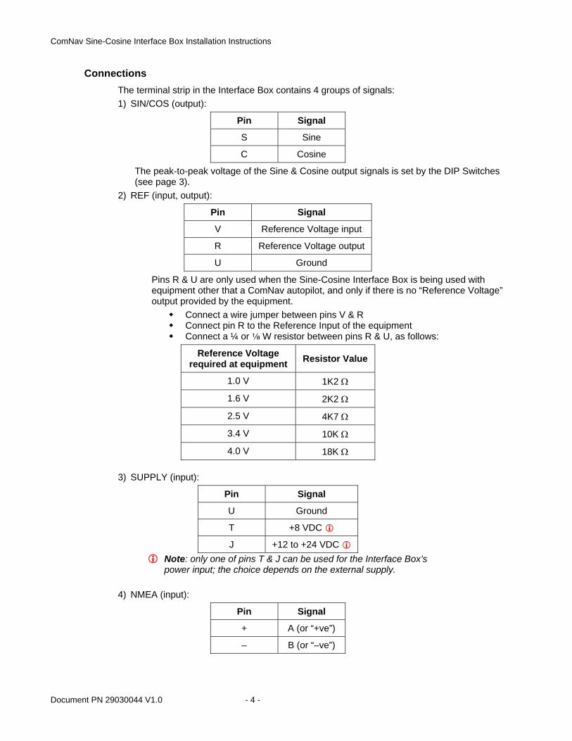
Connections The terminal strip in the Interface Box contains 4 groups of signals: 1) SIN/COS (output):
Pin Signal
S Sine
C Cosine
The peak-to-peak voltage of the Sine & Cosine output signals is set by the DIP Switches (see page 3).
2) REF (input, output):
Pin Signal
V Reference Voltage input
R Reference Voltage output
U Ground
Pins R & U are only used when the Sine-Cosine Interface Box is being used with equipment other that a ComNav autopilot, and only if there is no “Reference Voltage” output provided by the equipment.
Connect a wire jumper between pins V & R Connect pin R to the Reference Input of the equipment Connect a ¼ or c W resistor between pins R & U, as follows:
Reference Voltage required at equipment Resistor Value
1.0 V 1K2 Ω
1.6 V 2K2 Ω
2.5 V 4K7 Ω
3.4 V 10K Ω
4.0 V 18K Ω
3) SUPPLY (input):
Pin Signal
U Ground
T +8 VDC
J +12 to +24 VDC Note: only one of pins T & J can be used for the Interface Box’s
power input; the choice depends on the external supply.
4) NMEA (input):
Pin Signal
+ A (or “+ve”)
– B (or “–ve”)
Document PN 29030044 V1.0 - 4 -
ComNav Sine-Cosine Interface Box Installation Instructions
NMEA Configuration NMEA Data Source
The NMEA data source must be configured to transmit sentences at the NMEA 0183 standard settings: 4800 Baud, 8 bits, no parity, one stop bit. It must transmit the data with at least 100 milliseconds between successive sentences. The data source should be set to transmit only one of the three possible Heading sentences: 1) HDT, if you wish to have the autopilot steer the vessel on Headings in Degrees True 2) HDG, if you wish to have the autopilot steer the vessel on Headings in Degrees Magnetic 3) HDM, if you wish to have the autopilot steer the vessel on Headings in Degrees Magnetic The source’s setting for NMEA checksums must match the setting of the CHK-SUM jumper on the Sine-Cosine Interface Box (see the figure on page 3). For best operation with ComNav or SI-TEX autopilots mentioned earlier, the NMEA data source must output Heading data sentences at no less than a 5 Hz update rate (10 Hz or more is preferable).
Status LEDs The Interface Box has two status LEDs.
– The NMEA LED indicates that data signals are being received on the NMEA + and NMEA – pins.
It does not indicate that those signals are properly formatted, or even that the signal wires are correctly polarized (i.e., as NMEA “A” & “B” signals); it only indicates that there is “signal activity” – i.e., transitions between logical ‘1’ & ‘0’ bit states – on the pair of signal wires.
– The OK LED indicates that the NMEA data signals being received on the NMEA input (+, –) pins are valid: that is, the sentences are correctly formatted, & have checksums according to the CHK-SUM jumper. It also indicates that valid Sine & Cosine signals, corresponding to the heading data values in the received NMEA sentences (HDT, HDG or HDM, as noted above), should be appearing on the box’s Sin & Cosine output pins.
Note: if the Heading sentences being received have Null data (for example, a $GPHDT,,T*xx sentence), the Sine/Cosine output signals will typically remain at the voltages that existed when the Heading sentences last had non-Null data. This condition can occur, for example, in Vector G2/G2B GPS Compasses, during start-up, or during extended periods of loss of GPS satellite signals (see the Vector G2/G2B manual for more information).
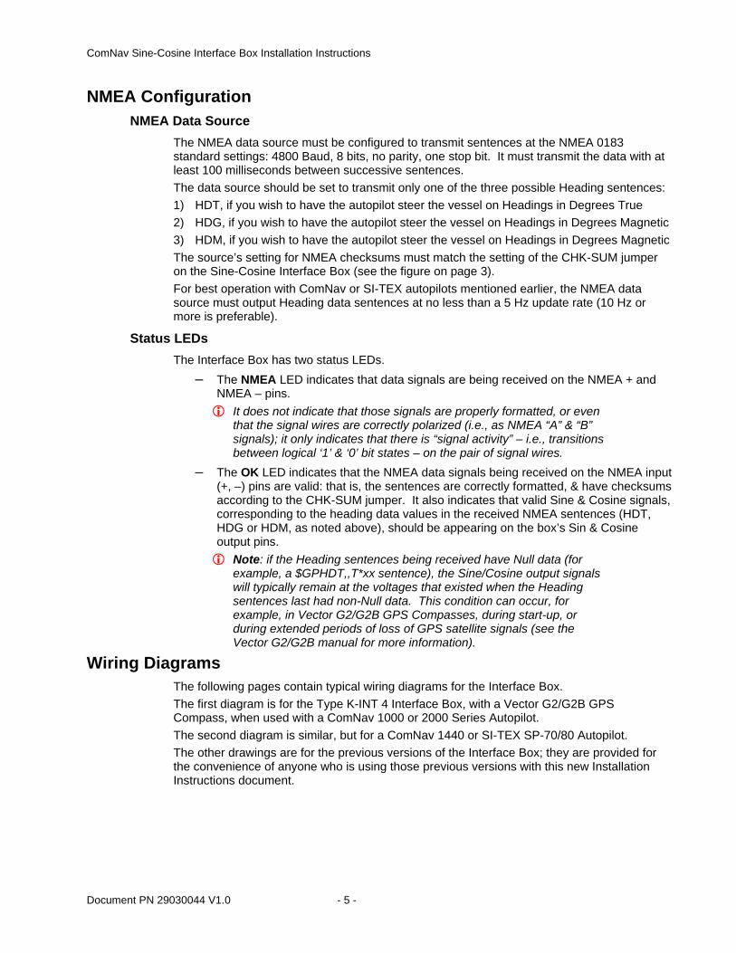
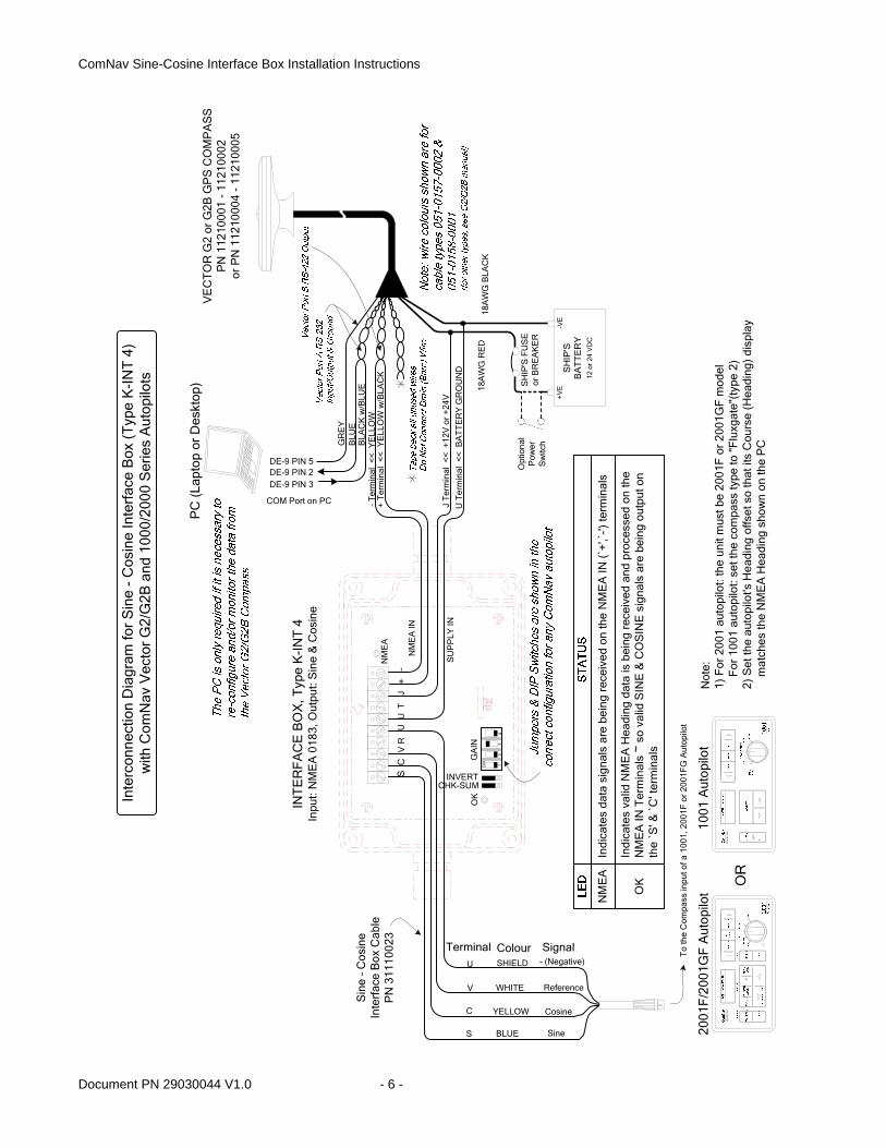
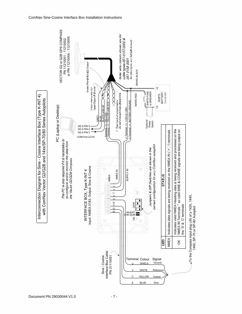
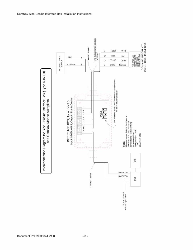
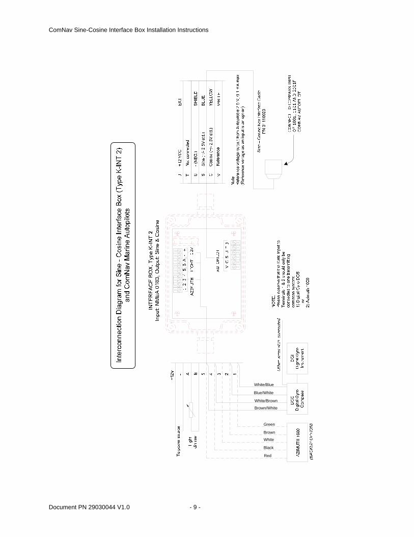
Wiring Diagrams The following pages contain typical wiring diagrams for the Interface Box. The first diagram is for the Type K-INT 4 Interface Box, with a Vector G2/G2B GPS Compass, when used with a ComNav 1000 or 2000 Series Autopilot. The second diagram is similar, but for a ComNav 1440 or SI-TEX SP-70/80 Autopilot. The other drawings are for the previous versions of the Interface Box; they are provided for the convenience of anyone who is using those previous versions with this new Installation Instructions document.
Document PN 29030044 V1.0 - 5 -
ComNav Sine-Cosine Interface Box Installation Instructions
Document PN 29030044 V1.0 - 6 -
BLUE SineS
Cosine
Reference
– (Negative)
WHITE
YELLOW
SHIELD
V
C
U
M A
R I
N E
2001
F/2
001G
F A
utop
ilot
OR
BLA
CK
w/B
LUE
INT
ER
FA
CE
BO
X, T
ype
K-I
NT
4
Inpu
t: N
ME
A 0
183,
Out
put:
Sin
e &
Cos
ine
VS
CU
+J
GA
IN
CHK-SUM
OK
INVERT
NM
EA
–N
ME
A IN
PC
(La
ptop
or
Des
ktop
)
DE-9 PIN 2DE-9 PIN 3
DE-9 PIN 5
GR
EY
BLU
E
Opt
iona
l P
ower
S
witc
h
J T
erm
inal
<<
+12
V o
r +
24V
U T
erm
inal
<<
BA
TT
ER
Y G
RO
UN
D
VE
CT
OR
G2
or G
2B G
PS
CO
MP
AS
SP
N 1
1210
001
-11
2100
02
or P
N 1
1210
004
-11
2100
05
12 o
r 24
VD
C
18A
WG
RE
D
SH
IP'S
FU
SE
or
BR
EA
KE
R
SH
IP'S
BA
TT
ER
Y
+V
E
18A
WG
BLA
CK
-VE
Not
e:1)
For
200
1 au
topi
lot:
the
unit
mus
t be
2001
F o
r 20
01G
F m
odel
F
or 1
001
auto
pilo
t: se
t the
com
pass
type
to "
Flu
xgat
e"(t
ype
2)2)
Set
the
auto
pilo
t's H
eadi
ng o
ffset
so
that
its
Cou
rse
(Hea
ding
) di
spla
y
mat
ches
the
NM
EA
Hea
ding
sho
wn
on th
e P
C
M A
R I
N E
1001
Aut
opilo
t
+ T
erm
inal
<<
YE
LLO
W w
/BLA
CK
– Ter
min
al <
< Y
ELL
OW
Terminal Colour Signal
NM
EA
OK
Indi
cate
s da
ta s
igna
ls a
re b
eing
rec
eive
d on
the
NM
EA
IN (
`+',`
-') te
rmin
als
Indi
cate
s va
lid N
ME
A H
eadi
ng d
ata
is b
eing
rec
eive
d an
d pr
oces
sed
on th
e N
ME
A IN
Ter
min
als
~ s
o va
lid S
INE
& C
OS
INE
sig
nals
are
bei
ng o
utpu
t on
the
`S' &
`C
' ter
min
als
UT
R
SU
PP
LY IN
COM Port on PC1
23
4
ON
Inte
rcon
nect
ion
Dia
gram
for
Sin
e -
Cos
ine
Inte
rfac
e B
ox (
Typ
e K
-IN
T 4
) w
ith C
omN
av V
ecto
r G
2/G
2B a
nd 1
000/
2000
Ser
ies
Aut
opilo
ts
Sin
e – C
osin
eIn
terf
ace
Box
Cab
leP
N 3
1110
023
To
the
Com
pass
inpu
t of a
100
1, 2
001F
or
2001
FG
Aut
opilo
t
ComNav Sine-Cosine Interface Box Installation Instructions
BLUE SineS
Cosine
Reference
Ground
WHITE
YELLOW
SHIELD
V
C
U
INT
ER
FA
CE
BO
X, T
ype
K-I
NT
4
Inpu
t: N
ME
A 0
183,
Out
put:
Sin
e &
Cos
ine
VS
CU
+J
GA
IN
CHK-SUM
OK
INVERT
NM
EA
–N
ME
A IN
PC
(La
ptop
or
Des
ktop
)
DE-9 PIN 2DE-9 PIN 3
DE-9 PIN 5
GR
EY
BLU
E
Opt
iona
l P
ower
S
witc
h
J T
erm
inal
<<
+12
V o
r +
24V
U T
erm
inal
<<
BA
TT
ER
Y G
RO
UN
D
VE
CT
OR
G2
or G
2B G
PS
CO
MP
AS
SP
N 1
1210
001
-11
2100
02
or P
N 1
1210
004
-11
2100
05
12 o
r 24
VD
C
18A
WG
RE
D
SH
IP'S
FU
SE
or
BR
EA
KE
R
SH
IP'S
BA
TT
ER
Y
+V
E
18A
WG
BLA
CK
-VE
+ T
erm
inal
<<
YE
LLO
W w
/BLA
CK
– Ter
min
al <
< Y
ELL
OW
Terminal Colour Signal
NM
EA
OK
Indi
cate
s da
ta s
igna
ls a
re b
eing
rec
eive
d on
the
NM
EA
IN (
`+',`
-') te
rmin
als
Indi
cate
s va
lid N
ME
A H
eadi
ng d
ata
is b
eing
rec
eive
d an
d pr
oces
sed
on th
e N
ME
A IN
Ter
min
als
~ s
o va
lid S
INE
& C
OS
INE
sig
nals
are
bei
ng o
utpu
t on
the
`S' &
`C
' ter
min
als
UT
R
SU
PP
LY IN
COM Port on PC
12
34
ON
Inte
rcon
nect
ion
Dia
gram
for
Sin
e -
Cos
ine
Inte
rfac
e B
ox (
Typ
e K
-IN
T 4
) w
ith C
omN
av V
ecto
r G
2/G
2B a
nd 1
4xx/
SP
-70/
80 S
erie
s A
utop
ilots
Sin
e – C
osin
eIn
terf
ace
Box
Cab
leP
N 3
1110
051
To
the
Com
pass
inpu
t plu
g (J
6) o
f a 1
420,
144
0,
1460
, SP
-70
or S
P-8
0 A
utop
ilot
BLA
CK
w/B
LUE
Document PN 29030044 V1.0 - 7 -
ComNav Sine-Cosine Interface Box Installation Instructions
INTE
RFA
CE
BOX,
Typ
e K-
INT
3In
put:
NM
EA 0
183,
Out
put:
Sine
& C
osin
e
V
C+
S+
U
DG
C
Cosine
Sine
- (NEG.)SHIELD
BLUE
YELLOW
WHITE
DG
I
NMEA TX+
NMEA TX-
+12/24 VDC J Reference
UV
J
U- (NEG)
U1
FRO
M B
ATTE
RY
SU
PPL
Y
TO C
OM
NA
VAU
TOPI
LOT'
SC
OM
PAS
S R
ECE
PTA
CLE
SUPP
LY (1
0-30
V)
DG
C'S
PO
WE
R
Cable
NOT
Sup
plied
Cable
NOT
Sup
plied
Sine
-Cos
ine In
terfac
e Box
Cab
lePN
3111
0023
CO
MN
AV
AU
TOP
ILO
T:20
01F,
100
1, 1
101&
120
1
SWIN
G
DIP
Sw
itche
s ar
e sh
own
in th
e co
rrec
t con
figur
atio
n fo
r any
Com
Nav
aut
opilo
t
12
34
ONTR
2
NO
TE:
Ple
ase
obse
rve
that
the
Dat
a In
put t
o Te
rmin
als
1 &
2 s
houl
d on
ly b
e co
nnec
ted
to o
ne tr
ansm
ittin
g co
mpa
ss s
yste
m:
1) D
igita
l Gyr
o D
GS
o
r2)
Azi
mut
h 10
00
Inte
rcon
nect
ion
Dia
gram
for S
ine
-Cos
ine
Inte
rface
Box
(Typ
e K
-INT
3)
and
Com
Nav
Mar
ine
Aut
opilo
ts
Document PN 29030044 V1.0 - 8 -
ComNav Sine-Cosine Interface Box Installation Instructions
Document PN 29030044 V1.0 - 9 -
Red
Black
Brown
Green
White
White/Brown
Blue/White
Brown/White
White/Blue
ComNav Sine-Cosine Interface Box Installation Instructions
A C
ON
NE
CTO
RB
CO
NN
EC
TOR
C C
ON
NE
CTO
R
To K
VH
Sen
sor M
odul
eP
N 2
1010
003
Powe
r In (
+)Gr
ound
In (-
)12
-32V
Pow
er S
ourc
e
Dip
Sw
itch
Mai
nten
ance
Por
t
NO
TE:
The
Ref
eren
ce v
olta
ge is
set
to 2
.5V
an
d th
e S
ine
-Cos
ine
swin
g to
2.0
V
Con
nect
to C
OM
PA
SS
IN o
f the
10
01, 1
101,
120
1 or
200
1F A
utop
ilot
Inte
rcon
nect
ion
Dia
gram
for K
VH
Gyr
oTra
c S
enso
r an
d C
omN
av M
arin
e/S
i-Tex
Aut
opilo
ts
Com
pass
Cab
leP
N 3
1110
023
Com
pass
Cab
leP
N 3
1110
051
Con
nect
to J
6 of
the
14xx
or S
P-7
0/80
Aut
opilo
t
Document PN 29030044 V1.0 - 10 -
ComNav Sine-Cosine Interface Box Installation Instructions
Document PN 29030044 V1.0 - 11 -
Technical Data Sine-Cosine Interface Box
• Supply Voltage: 8 VDC (Terminal T), or 12 - 24 VDC (Terminal J) • Supply Current: 15mA (without load, 8 VDC) • Power rating: 120mW • Isolation voltage: 5 KV (1 minute, AC) • NMEA Input:
– Compliant to NMEA 0183 protocol – Interface level: RS-422 (also accepts RS-232) – Port settings: 4800 Baud, 8 data bits, no parity,1 stop bit – Talker Load Current: 0.8 mA @ ±2 V, 2.3 mA @ ±6 V – Min. differential voltage: ±2 V – Min. time between sentences: 100 mS
Sine-Cosine Box Interface Cables PN 31000023
• Length: 3 metres (10’) • Connectors: ComNav-standard 7-pin Compass plug to flying wires • Internal resistors: 1 K Ω ¼ W in series in Sine & Cosine wires (Blue, Yellow),
10 K Ω ¼ W in series in Reference wire (White)
PN 31000051 • Length: 3 metres (10’) • Connectors: Flying wires both ends • Internal resistors: 1 K Ω ¼ W in series in Sine & Cosine wires (Blue, Yellow),
10 K Ω ¼ W in series in Reference wire (White)
ComNav Marine Ltd. #15 – 13511 Crestwood Place
Richmond, B.C. Canada V6V 2G1 www.comnavmarine.com
Tel: 604-207-1600 Fax: 604-207-8008


