Download - 21 Anaerobic Processes
Industrial Water Pollution Control
1
21. ANAEROBIC WASTEWATER TREATMENT PROCESSES
21.1 Background
Anaerobic biological treatment is well understood and used frequently as anaerobic digesters
to treat complex organic solid wastes such as primary and secondary wastewater sludges.
However, it has not been used much in the past to treat low strength organic wastewaters
from industrial and domestic applications. Aerobic processes were preferred for treatment of
these wastewater streams because they are easy to operate and can tolerate process
fluctuations. In comparison, anaerobic reactors were assumed to be less stable under
fluctuations, more expensive to install and require long start-up time. This belief was due to
limited knowledge of the process and reactor design.
Now the technology advances have significantly reduced the historical weakness of anaerobic
treatment. With the work of Young and McCarty in the year 1969, application of anaerobic
process for the treatment of industrial and municipal wastewaters has gradually increased in
last three decades. Today the anaerobic treatment has emerged as a practical and economical
alternative to aerobic treatment due to significant advantages over aerobic treatment.
21.2 Anaerobic Degradation of Organic matter
The factors that determine the removal efficiency of biodegradable organic matter are:
1. The nature and composition of the organic matter to be removed
2. Suitability of environmental factors
3. Sludge retention time in the reactor
4. The intensity of mixing, hence contact between bacterial biomass and organic matter.
5. Specific loading of organic matter with respect to bacterial sludge mass, and retention
time.
Factors (1) and (2) are basically dependent on wastewater characteristics, whereas (3) to (5)
are related to the type and design of the treatment system. The transformation of complex
macromolecules of organic matter present in wastewater into biogas requires several groups
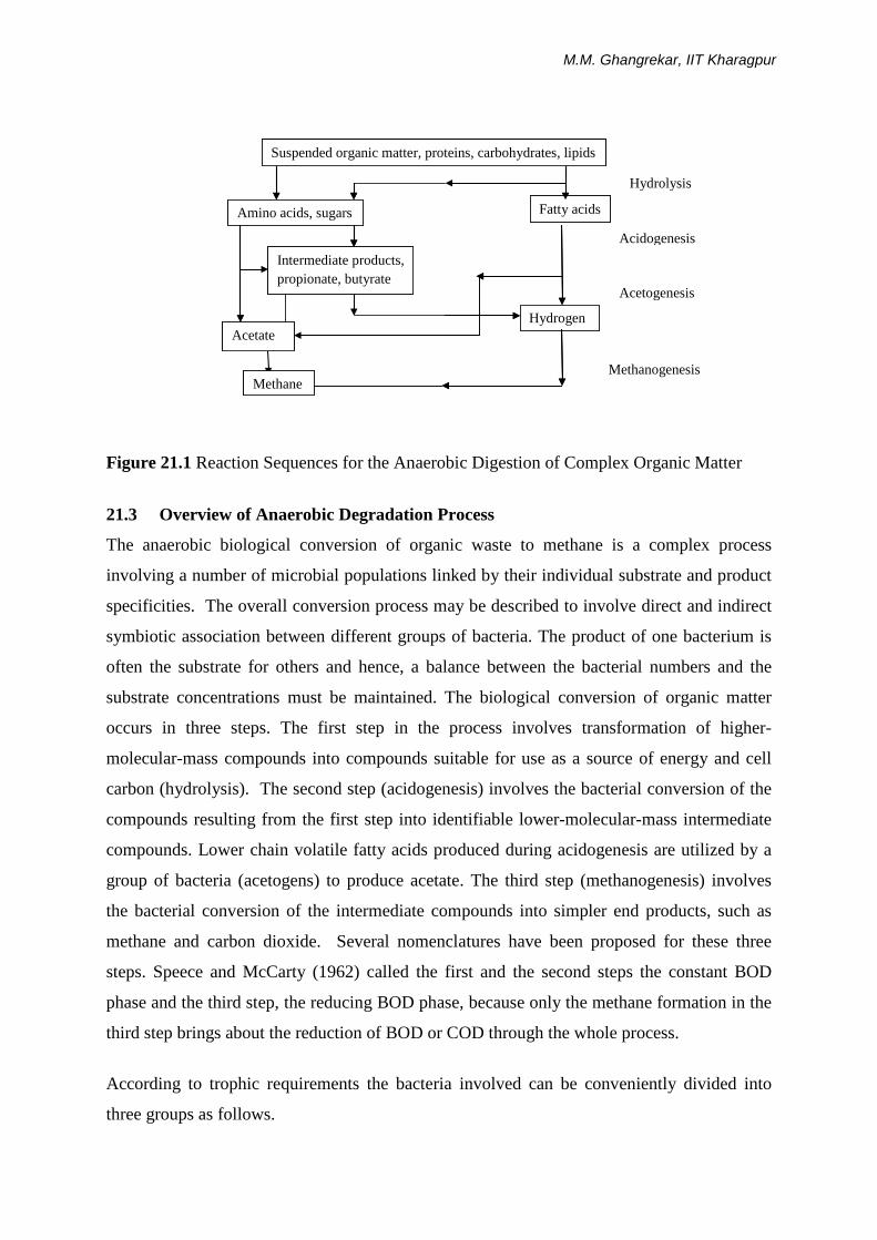
of microorganisms. The reaction sequence of the anaerobic digestion of complex
macromolecules is presented in Figure 21.1 [Gujer and Zehnder, 1983]. Different steps are
necessary for the anaerobic digestion of proteins, carbohydrates, and lipids. Four different
phases can be distinguished in the overall conversion process of organic matter to biogas as
1) Hydrolysis, 2) Acidogenesis, 3) Acetogenesis, and 4) Methanogenesis.
M.M. Ghangrekar, IIT Kharagpur
Figure 21.1 Reaction Sequences for the Anaerobic Digestion of Complex Organic Matter
21.3 Overview of Anaerobic Degradation Process
The anaerobic biological conversion of organic waste to methane is a complex process
involving a number of microbial populations linked by their individual substrate and product
specificities. The overall conversion process may be described to involve direct and indirect
symbiotic association between different groups of bacteria. The product of one bacterium is
often the substrate for others and hence, a balance between the bacterial numbers and the
substrate concentrations must be maintained. The biological conversion of organic matter
occurs in three steps. The first step in the process involves transformation of higher-
molecular-mass compounds into compounds suitable for use as a source of energy and cell
carbon (hydrolysis). The second step (acidogenesis) involves the bacterial conversion of the
compounds resulting from the first step into identifiable lower-molecular-mass intermediate
compounds. Lower chain volatile fatty acids produced during acidogenesis are utilized by a
group of bacteria (acetogens) to produce acetate. The third step (methanogenesis) involves
the bacterial conversion of the intermediate compounds into simpler end products, such as
methane and carbon dioxide. Several nomenclatures have been proposed for these three
steps. Speece and McCarty (1962) called the first and the second steps the constant BOD
phase and the third step, the reducing BOD phase, because only the methane formation in the
third step brings about the reduction of BOD or COD through the whole process.
According to trophic requirements the bacteria involved can be conveniently divided into
three groups as follows.
Suspended organic matter, proteins, carbohydrates, lipids
Amino acids, sugars Fatty acids
Intermediate products, propionate, butyrate
Hydrogen Acetate
Methane
Hydrolysis
Acidogenesis
Acetogenesis
Methanogenesis
Suspended organic matter, proteins, carbohydrates, lipids
Amino acids, sugars Fatty acids
Intermediate products, propionate, butyrate
Hydrogen Acetate
Methane
Hydrolysis
Acidogenesis
Acetogenesis
Methanogenesis
Suspended organic matter, proteins, carbohydrates, lipids

Industrial Water Pollution Control
3
Hydrolytic bacteria - acidogens: These bacteria hydrolyze the substrate (macromolecule)
into short-chain organic acids and other small molecules, which can be taken up and
converted into soluble short-chain organic molecules, e.g., carbohydrates are converted into
low-chain fatty acids, alcohols, hydrogen and carbon dioxide under anaerobic condition.
Strict anaerobes are composed most part of this group of bacteria. The generation time of
these bacteria is 2 to 3 hours. The principle intermediate compounds resulting from
conversion of the substrate during acid fermentation are acetate (CH3COOH), propionate
(CH3CH2COOH), butyrate (CH3CH2CH2COOH), hydrogen gas (H2), carbon dioxide (CO2),
lactate (CH3CHOHCOOH), formate (HCOOH), ethanol (CH3CH2OH), valeric acid
(CH3CH2CH2CH2COOH), isovaleric acid ((CH3)2CHCH2COOH), and caproic acid
(CH3CH2CH2CH2CH2COOH). The distribution of final product depends on the species of
acidogenic bacteria and on the environmental conditions such as pH and temperature.
Obligate Hydrogen Producing Acetogens (OHPA): This group converts compound formed
in the first stage into acetic acid and hydrogen. Low hydrogen pressure favours these
reactions [Harper and Pohland, 1986].
e.g. Propionate CH3CH2COOH + 2H2O → CH3COOH + CO2 + 3H2
ΔGo = 76.1 KJ/mole
Butyrate CH3CH2CH2COOH + 2H2O → 2CH3COOH + 2H2
ΔGo = 48.1 KJ/mole
From the viewpoint of the thermodynamics, a negative value of free energy change is
necessary for any reaction to proceed without input of external energy. This theory apparently
suggests that hydrogen producing acetogenic bacteria cannot obtain energy for growth from
these reactions. However, the value of free energy change in the actual environment
surrounding the bacteria, ΔG', is different from that of ΔGo' and depends on the
concentrations of substrates and products as follows [Harper and Pohland,1986]:
[P1].[P2].... ΔG' = ΔGo' + RTA ln ------------------ ....(1)
[S1].[S2].... Where,
ΔG' = free energy change at pH = 7 (kJ/mol),
ΔGo' = standard free energy change at pH = 7 (kJ/mol),
R = gas constant = 0.082 L.atm/mol.oK,
TA = temperature (oK),

M.M. Ghangrekar, IIT Kharagpur
[P1].[P2]... = product concentration (mol/L or atm), and
[S1].[S2]... = substrate concentration (mol/L or atm).
Only low partial pressure of hydrogen can give negative values of ΔG' in above equations,
because substrate concentration cannot be so high and acetate concentration is not so low in
anaerobic reactors. This shows that extremely low partial pressure of hydrogen is essential for
hydrogen producing acetogenic bacteria although they themselves produce hydrogen.
Experimentally it was found that the hydrogen partial pressure higher than 5 x 10⁻³ atm
ceased the degradation of propionate by hydrogen producing acetogenic bacteria [Hanaki et
al., 1985]. Based on thermodynamics associated with this reactions Harper and Pohland
[1985] indicated that propionic acid oxidation to acetate becomes favourable only at
hydrogen partial pressure below 10-4 atm, while, butyric acid oxidation becomes favourable
at 10-3 atm H2 or below.
Hydrogen utilizing methanogenic bacteria can serve such a thermodynamically favourable
conditions for hydrogen producing acetogenic bacteria in anaerobic reactors, thus, the activity
of hydrogen producing acetogenic bacteria depends on the existence of methanogenic
bacteria. Hydrogen utilizing methanogens receive hydrogen as a substrate from hydrogen
producing acetogenic bacteria. The interrelationship between these two groups of bacteria is
called interspecies hydrogen transfer, which also exists between acidogenic and
methanogenic bacteria. Acidogenic bacteria produce more hydrogen and acetate than
propionate or lactate and obtain more energy under low hydrogen partial pressure which is
kept by methanogenic bacteria. The interspecies hydrogen transfer is favourable but not
essential for acidogenic bacteria, while, it is indispensable for hydrogen producing acetogenic
bacteria.
Methanogenic bacteria - methanogens: These bacteria produce methane. The doubling
time of these bacteria is 2 - 10 days. These are further divided into two groups as:
a) Hydrogen utilisers (lithotrophs)
CO2 + 4H2 → CH4 + 2H2O convert ADP to ATP
b) Acetic acid users (acetotrophs)
CH3COOH → CH4 + CO2 produce 0.25 mole of ATP
The methane producing bacteria are strict anaerobes which are extremely sensitive to changes
in temperature and pH. These bacteria are active in two temperature zones, namely, in the
mesophilic range (30oC - 35oC) and in the thermophilic range (50oC - 60oC). However,

Industrial Water Pollution Control
5
anaerobic processes have been operated at 15oC successfully when sufficient residence time
for these bacteria was provided.
The majority of methanogens in anaerobic wastewater treatment and natural anaerobic
environment utilize hydrogen and single carbon compounds as substrates for methane
production. In addition there are two known genera of methanogens which can utilize the
two-carbon compound, acetic acid. These include species of Methanosarcina and
Methanothrix (Methanosaeta). The Methanothrix species are unable to use hydrogen in
combination with CO2 and these are non-hydrogen-oxidizing acetotrophs (NHOA). In
contrast, Methanosarcina can utilize H2/CO2 as well as acetate, carbon monoxide,
methanol, and methylamines as growth substrates. Due to their ability to use both H2/CO2
and acetate, these bacteria are classified as Hydrogen Oxidizing Acetotrophs (HOA).
Hydrogen-Oxidizing Methanogens (HOM) do not cleave acetate, but utilize H2/CO2 and
formate as substrates [Harper and Pohland, 1986]. The HOA are unique in their capability to
utilize multiple (one and/or two carbon) substrates. This ability affords a higher potential for
survival when competing with sulfur reducing bacteria (SRB) and nitrate reducing bacteria
(NRB) for hydrogen and acetate. At hydrogen partial pressure >10-4 atm, HOA use H2/CO2
in favour of acetate, whereas acetate cleavage by NHOA is unaffected by hydrogen.
NHOA have a much higher affinity for acetate than the HOA. NHOA may outcompete HOA
at acetate concentrations below 50 mg/L, while above 250 mg/L acetate, the HOA are more
competitive [Speece et al., 1983]. As a result of this comparative kinetics Methanothrix
(NHOA) may be found in reactors with lower organic loading. Methanosarcina are more
predominant in low retention time reactors such as in the lower reaches of plug flow
anaerobic filters and in two phase reactor system.
Oxidation of reduced organic products to bicarbonate and acetate also occurs due to NRB and
SRB. Higher organic waste conversion rates may be available through SRB than through
methanogenesis. Moreover, SRB and NRB are not limited to one-and two-carbon substrates,
as are methanogens. However, from process engineering perspective, such an approach has
disadvantages, including the loss of energy available from methane and the production of
hydrogen sulphide or ammonia. Since, sulphide and ammonia are much more soluble than
methane, their dissolved components can contribute significantly to effluent COD [Harper

M.M. Ghangrekar, IIT Kharagpur
and Pohland, 1986]. However, this approach may hold possibilities for reducing propionic
acid and hydrogen, as well as acetic acid in a stressed reactor, in order to more rapidly
reestablish the equilibrium with the existing hydrogen removal system.
21.4 Factors Affecting Anaerobic Digestion
Development of anaerobic process technology is dependent on a better understanding of the
factors that are associated with the stability of the biological processes involved. Process
instability is usually indicated by a rapid increase in the concentration of volatile acids in the
first stage of the reaction. Low pH with a concurrent reduction in methane gas production
indicates the methanogenesis more susceptible to upset. Acclimatization of the microbes to a
substrate may take 3 to 8 weeks. Sufficiently acclimated bacteria show greater stability
towards stress-inducing events such as hydraulic overloads, fluctuations in temperature,
volatile acid and ammonia concentrations, etc. Several environmental factors can affect
anaerobic digestion such as specific growth rate, decay rate, gas production, substrate
utilization, etc. The environmental factors of primary importance are discussed below.
21.4.1 pH, Acidity and Alkalinity
Methanogenic microorganisms are susceptible to the minute changes in the pH values.
Optimum pH range of 6.6 – 7.6 is considered favourable for the methane producing bacteria,
which cannot tolerate the fluctuations. The non-methanogenic bacteria do not exhibit such
strong sensitivity for environmental conditions and are able to function in a range of pH form
5 – 8.5. The pH maintained inside the reactor, due to the process results from the interaction
of the carbon dioxide-bicarbonate buffering system and volatile acids-ammonia formed by
the process. It is necessary to prevent the accumulation of acids to a level, which may
become inhibitory to the methanogenic bacteria. For this, it is important that there should be
sufficient buffering capacity present in the reactor, which may prevent the reactor from
souring. Although, the carbonates and bicarbonates of sodium and calcium are required to be
added to the digesters to provide buffering action, lime (Calcium hydroxide) is most
commonly used for this purpose. Only the unionized volatile acids in the concentration range
of 30 - 60 mg/L are toxic.
21.4.2 Temperature
As in all biological processes, anaerobic processes are affected by temperature. The higher
the temperature, higher is the microbial activity until an optimum temperature is reached. A
Industrial Water Pollution Control
7
further increase of the temperature beyond its optimum value results in steep decrease in
activity. Anaerobic process can take place over a wide range of temperatures (4 – 600C).
Once as effective temperature is established, small fluctuations can result in a process upset.
Although most of the sludge digester are operated in the mesophilic range (30 – 400C),
methanogenesis can occur at temperatures as low as 12 to 150C. The effect of increasing
temperature on biochemical reaction rate in the range of 4 – 250C is profound.
The optimum temperature for growth of anaerobic microorganisms is 350C or greater.
Although anaerobic digesters have been reported to operate at substantially lower
temperatures, such as 200C, anaerobic growth under these temperature conditions is slow
requiring prolonged start-up time and difficulties in operation. In situations where reactor’s
operating temperature is low, start-up will be benefited if initiated at approximately 350C. At
temperature of less than 250C, the digestion rate decreases sharply and conventional
anaerobic reactors in operation at ambient temperatures in cooler climates may require
detention times of as much as 12 weeks for the treatment of sewage sludges.
The majority of industrial digester systems operate in the mesophilic range of 30 – 400C. It is
probable that increase in microbial reaction rates at the elevated temperatures of thermophilic
processes (50 – 600C), and hence decrease in SRT may prove advantageous under some
circumstances. However, lack of stability in thermophilic municipal waste treatment can
occur. Thermophilic digestion is most practical where wastewater stream to be treated is
discharged at an extremely high temperature and the digester is present on site.
In psycrophilic, mesophilic, or thermophilic ranges, uniformity of temperature over the entire
vessel contents is of paramount importance to anaerobic digestion. Temperature change of
even a few degrees can result in a marked upset in microbial metabolism and rapid alterations
in reactions in the reactor and may necessitate several days for the recovery. A consistent
temperature throughout the system can be provided by adequate mixing of the reactor by
paddle, gas sparging, or flow over heat exchangers.
21.4.3 Nutrients
Anaerobic wastewater treatment processes are often used for industrial waste with only minor
amount of nutrients present. This might result in nutrient deficiency, unless additional
nutrients are supplemented. Often the COD/N ratio and COD/N/P ratio is used to described

M.M. Ghangrekar, IIT Kharagpur
the nutrient requirements. Optimum N/P ratio can be considered to be 7. The theoretical
minimum COD/N –ratio is considered to be 350/7. A value around 400/7 is considered
reasonable for high rate anaerobic processes (0.8 – 1.2 kg COD /kg VSS.d). For low rate
processes (<0.5 kg COD /kg VSS.d) the COD/N-ratio has been observed to be increased
dramatically to values of 1000/7 or more [Van den Berg and Lentz, 1980].
Other than nitrogen and phosphorous, trace metals also are essential for anaerobic processes.
The presence of trace metals such as molybdenum, selenium, tungsten and nickel is probably
necessary for the activity of several enzyme systems. When these trace elements are not
present in the wastewater, addition of nickel, cobalt, and molybdenum can increase methane
production and allow greater volumes of wastewater to be effectively treated by decreasing
the reactor residence time.
21.4.4 Inhibitory Substances
Inhibition of the anaerobic digestion process can be mediated to varying degrees by toxic
materials present in the system. These substances may be components of the influent
wastewater or byproducts of the metabolic activities in the digester. Inhibitory toxic
compounds include sulphides, consequential in the processing of waste from sources such as
molasses fermentation, petroleum refining and tanning industries. Volatile acid and other
microbial products can accumulate and inhibit reactor-buffering capacity. Inhibition may
also arise as the consequence of the increased levels of ammonia, alkali, and the alkaline
earth metals, and heavy metals in the system.
Volatile Acids Inhibition: Anaerobic reactor instability is generally evident by a marked and
rapid increase in volatile fatty acids concentrations; this is frequently indicative of the failure
of the methanogenic population due to other environmental disruptions such as shock
loadings, nutrient depletion or infiltration of inhibitory substances. Acetate has been
described as the least toxic of the volatile acids, while propionate has often been implicated
as a major effecter of digester failure.
The inhibition by the volatile acids at acidic pH values can be attributed to the existence of
unionized VFAs in significant quantities in the system. The undissociated nature of these
acids allow them to penetrate the bacterial cell membrane more efficiently than their ionized
counterparts, and once assimilated, induce an intracellular decrease in pH and hence a
decrease in microbial metabolic rate. The resulting VFA concentration in the reactor should
Industrial Water Pollution Control
9
be maintained below 500 mg/L at any point of time and preferably below 200 mg/L for
optimum performance.
Ammonia – Nitrogen Inhibition: Although ammonia is an important buffer in anaerobic
processes, high ammonia concentration can be a major cause of operational failure. In reactor
system that has not previously been acclimated to high ammonia loadings, shock loadings of
high ammonia concentration generally caused rapid production of VFAs such that the
buffering capacity of the system may not be able to compensate for the decrease in pH.
Further depression of alkalinity and reduction of pH may result in reactor failure. Inhibition
is indicated by a decrease in gas production and an increase in volatile acid formation.
Sulphide Inhibition: The sulphate and other oxidized compounds of sulphur are easily
reduced to sulphide under the conditions prevalent in anaerobic digesters. Sulphur-containing
amino acids of protein can also undergo degradation to sulphide. These compounds are of
significance when anaerobic treatment is considered for industrial processes which tend to
produce large quantities of sulphides in their waste stream. These sulphides formed by the
activity of reactor microorganisms may be soluble or insoluble, depending upon their
associated cations. When the salts formed are insoluble, they have negligible effects on
digestion. Iron addition, for example can suppress sulphide inhibition by removing S2- ion
from solution by precipitation.
Desulfovibrio and other sulphate-reducing genera form sulphides from sulphates and some of
the fermentative microorganisms utilize the sulphur containing amino acids to produce
sulphides. Sulphide concentration in excess of 200 mg/L in a digester at 35 0C, with
continuous feeding and mixing, produced severe inhibitory effects including the complete
cessation of gas production [Parkin and Speece, 1983]. All the heavy metals, with the
exception of chromium, form insoluble sulphide salts and thus can be removed from solution
by sulphide present in the system by precipitation. Free sulphide can also be eliminated as
hydrogen sulphide by vigorous gas production.
Heavy Metals Inhibition: The most common agents of inhibition and failure of sewage
sludge digesters are identified to be contaminating heavy metals. Heavy metals in the soluble
state are in general regarded to be of more significance to reactor toxicity than are insoluble
forms. Anaerobic digestion also reduces the valence states of some heavy metals. Both
M.M. Ghangrekar, IIT Kharagpur
copper and iron may be reduced from the trivalent to divalent state. This reduces the quantity
of the precipitating agent, such as sulphide, necessary for the removal of the metal ion from
solution. The heavy metals can be removed from anaerobic systems by adsorption. Those
digesters, such as the CSTR configuration; which are tolerant to the wastes containing high
levels of suspended solids are effective in metal removal, provided sufficient adsorption sites
are present. The metals like copper, chromium, nickel, lead can induce toxicity in the reactor
when present in higher concentration, and acceptable concentration in the wastewater to be
treated differs from metal to metal.
21.5 Merits of Anaerobic Decomposition Process
It has been recognized that the anaerobic treatment is in many ways ideal for wastewater
treatment and has several merits mentioned as below:
• A high degree of waste stabilization;
• A low production of excess biological sludge and this sludge can be directly dried on
sludge drying bed without further treatment due to better dewatering ability;
• Low nutrient requirements, hence anaerobic treatment is attractive for the treatment of
wastewater where external nutrient addition is required;
• No oxygen requirement, hence saving in power required for supply of oxygen in aerobic
methods;
• Production of valuable byproduct, methane gas;
• Organic loading on the system is not limited to oxygen supply hence higher loading rate
as compared to aerobic processes can be applied.
• Less land required as compared to many aerobic process.
• Non-feed conditions for few months do not affect adversely to the system and this makes
it attractive option for seasonal industrial wastewater treatment.
Quantity of biological solids produced in the anaerobic systems per unit weight of organic
material is much less than that in aerobic systems. This is a major advantage of the anaerobic
process as the quantity of sludge for ultimate disposal is reduced. This is a result of
conversion of volatile solids present, to the high energy level end products such as methane,
carbon dioxide and water. Methane has a definite economic value as a fuel, and it is used as
a source of energy for both heat and power in many installations.
Another major advantage is the loading potential. Aerobic processes are restricted in
maximum organic loading rate by the inability to transfer oxygen at the rate sufficient to
Industrial Water Pollution Control
11
satisfy the oxygen demand of the systems. The stabilized sludge from anaerobic process may
be free from strong or foul odours and can be used for land application as ultimate disposal
because the digested sludge contains sufficient nutrients required for plants. Pathogens are
also destroyed to a high degree during the thermophilic anaerobic process. Due to large
retention time and consequent low growth rate, the cell yield is also extremely low; thus,
most of the carbon in the waste is available for methanogenesis and under normal
circumstances the yield of methane would, on an average, be 0.33 – 0.36 m3 per kg COD
utilized at 35oC and atmospheric pressure.
However, anaerobic treatment processes are not largely being implemented, because of many
factors. Anaerobic microorganisms, especially methanogens have slow growth rate. At lower
HRTs, the possibility of washout of biomass is more prominent due to higher upflow
velocity. This makes it difficult to maintain the effective number of useful microorganisms
in the system. To maintain the population of anaerobes, large reactor volume or higher HRTs
with low upflow velocity are required. This may ultimately provide longer SRTs more than
40 days for high rate systems. Thus, provision of larger reactor volume or higher HRTs
ultimately leads to higher capital cost. Low synthesis / reaction rate hence, long start-up
periods and difficulty in recovery from upset conditions are some of the notable
disadvantages. Special attention is therefore required towards controlling the factors that
affect process adversely; importantly among them being environmental factors such as,
temperature, pH, and concentration of toxic substances. Hence, skill supervision is required
for operating anaerobic reactor at optimal performance.
21.6 Anaerobic Waste Treatment Processes
Advantage of anaerobic waste treatment systems as means for recovery of non-conventional
energy is increasingly being recognized worldwide. Anaerobic decomposition is a
biologically mediated process, indigenous to nature, and capable of being simulated for
treating wastes emanating from municipal, agricultural, and industrial activities. Anaerobic
digestion as applied in treatment of sewage sludge and other organic wastes, represents the
controlled application of a process. Although, anaerobic digesters have traditionally been
used for many decades in the stabilization of sewage sludge, their successful and economic
employment for the treatment of liquid wastes is only a recent phenomenon, arising from the
development of new reactor designs. These concepts have led to development of various
reactors, which are capable of retaining a much higher biomass concentration than traditional

M.M. Ghangrekar, IIT Kharagpur
digesters. Making the sludge retention independent of the influent retention time makes this
possible. The technological approaches to allow this condition of independent sludge
retention time can be divided in to the following:
• Attachment of biomass on the media (filters, fluidized systems, and RBC configurations);
• Non-attached biomass concept as suspended growth process (sludge blanket reactors and
contact process with sludge recycling).
It is difficult to evaluate the advantages and disadvantages of each system in relation to other
concepts, as generalizations are not usually valuable in practice. Considerations such as,
purification rates, loading rates, investment cost, energy balance, space requirements,
operational costs, and specific long term experience with certain wastewaters are all
important, but they will be valued differently from industry to industry. Various anaerobic
reactor types in practice are summarized in Table 21.1.
Table 21.1 Basic Types of Reactors used in Anaerobic Process
Type of reactor Synonyms Abbreviations Attached Biomass Fixed Bed Fixed film, filter, submerged filter,
/stationary fixed bed SMAR (Submerged anaerobic reactor)/ ANFIL (upflow anaerobic filter), AUF (Anaerobic upflow filter), ADSR (Anaerobic downflow stationary bed reactor), AF (anaerobic filter), DSFF (downflow stationary fixed film reactor)
Moving Bed Rotting discs, Rotating biological contactor,
AnRBC, RBC
Expanded bed Anaerobic attached film expanded bed
AAFEB
Fluidized bed Anaerobic Fluidized bed reactor, Carrier-assisted contact process
FBBR / IFCR (Immobilized fluidized cells reactor)/ CASBER (Carrier-assisted sludge bed reactor)
Non-attached Biomass Recycled flocks, Sludge blanket, Digester
Contact process, Upflow anaerobic sludge blanket reactor (UASB), Upflow sludge blanket (USB), Clarigester type
UASB, USB
(Reference: Henze and Harremoes, 1983)
In suspended growth systems microbial cultures are freely suspended in the reactors.
Microorganisms are suspended in the wastewater, as a single cell or as their agglomerates.
Industrial Water Pollution Control
13
Various reactor types developed on the principles of suspended growth are discussed
hereunder. The anaerobic contact process essentially involves two phases. A contact phase,
where the raw waste is intimately mixed with a previously developed and available anaerobic
sludge culture in the reactor; and a separation phase, where the active sludge particles are
separated from the treated liquor and recycled to the contact unit. In this process, raw
wastewater is mixed with recycled sludge solids and then digested in a digestion chamber.
After digestion, the mixture is separated in a clarifier (or vacuum flotation unit), and the
supernatant is discharged as effluent. Settled sludge is then recycled to seed the incoming
waste.
The loading rates permissible in an anaerobic waste treatment process are primarily dictated
by the sludge retention in an anaerobic reactor. The maintenance of high Sludge Retention
Time (SRT) has been the major problem in the practical application of the process, especially
for waste with Chemical Oxygen Demand (COD) below about 3000 mg/L. Obviously, a
waste treatment process for low-strength wastes is an economical one if large volume of
waste can be forced through the system in a relatively short time period. For this purpose
process are required in which the biomass retention time can be controlled independently of
the wastewater flow rate. Conventional anaerobic treatment processes of the flow-through
type are therefore inadequate to treat low-strength wastes.
Advances in the understanding of how anaerobic system function, improved understanding of
mixing and mass transfer, and anaerobic reactor design, has led to the evolution of a new
generation of high-rate anaerobic processes e.g. Anaerobic Filters (AF), Anaerobic expanded
/ Fluidized bed rectors, Upflow Anaerobic Sludge Blanket (UASB) Reactor, etc. These
systems have been schematically presented in Figure 21.2 and Figure 21.3.
M.M. Ghangrekar, IIT Kharagpur
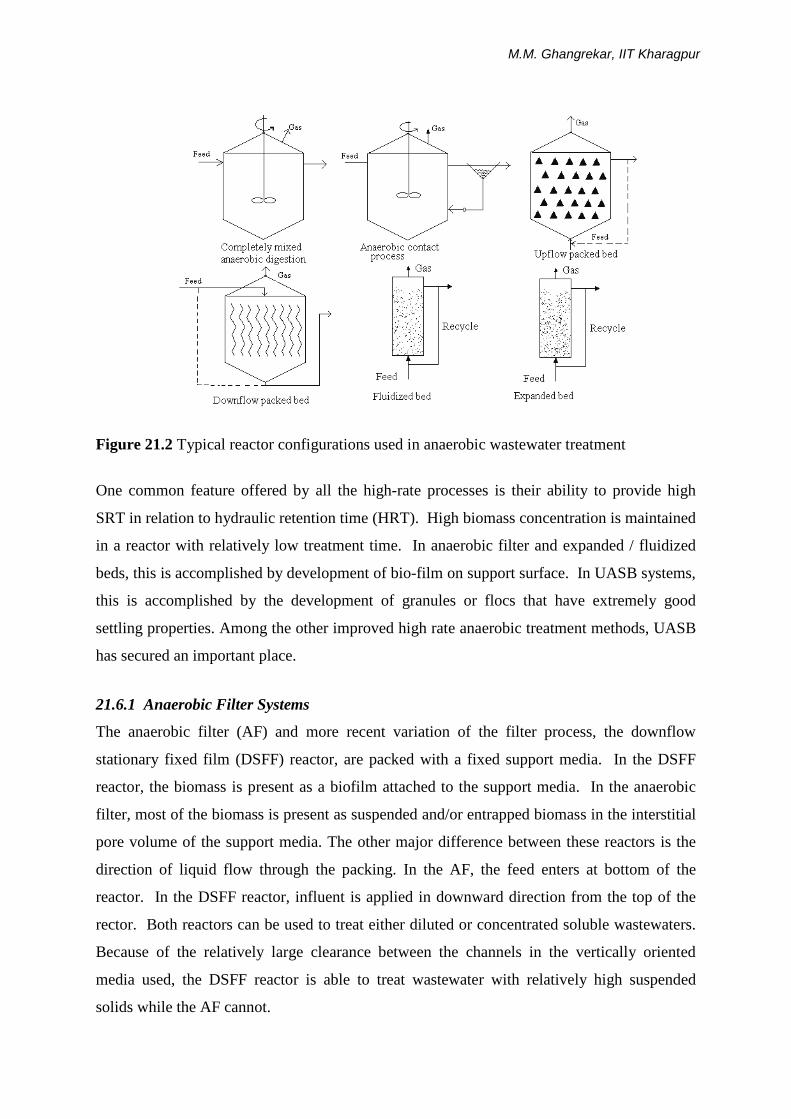
Figure 21.2 Typical reactor configurations used in anaerobic wastewater treatment
One common feature offered by all the high-rate processes is their ability to provide high
SRT in relation to hydraulic retention time (HRT). High biomass concentration is maintained
in a reactor with relatively low treatment time. In anaerobic filter and expanded / fluidized
beds, this is accomplished by development of bio-film on support surface. In UASB systems,
this is accomplished by the development of granules or flocs that have extremely good
settling properties. Among the other improved high rate anaerobic treatment methods, UASB
has secured an important place.
21.6.1 Anaerobic Filter Systems
The anaerobic filter (AF) and more recent variation of the filter process, the downflow
stationary fixed film (DSFF) reactor, are packed with a fixed support media. In the DSFF
reactor, the biomass is present as a biofilm attached to the support media. In the anaerobic
filter, most of the biomass is present as suspended and/or entrapped biomass in the interstitial
pore volume of the support media. The other major difference between these reactors is the
direction of liquid flow through the packing. In the AF, the feed enters at bottom of the
reactor. In the DSFF reactor, influent is applied in downward direction from the top of the
rector. Both reactors can be used to treat either diluted or concentrated soluble wastewaters.
Because of the relatively large clearance between the channels in the vertically oriented
media used, the DSFF reactor is able to treat wastewater with relatively high suspended
solids while the AF cannot.
Industrial Water Pollution Control
15
Because the bacteria are retained on the media and not washed off in the effluent, mean cell
residence times of the order of 100 days can be obtained. Large values of θc can be achieved
with short hydraulic retention times, so the anaerobic filters can be used for the treatment of
low-strength wastewater at ambient temperature. In the AF, most of the biological activity is
due to the biomass in suspension (entrapped) rather than to the attached biofilm. The media
with a high capacity to entrap and prevent washout of the biomass from the reactor is more
important than the specific surface area (surface area to volume ratio) of the media. The
biofilm thickness of 1 to 3 mm has been observed in fixed-bed reactor.
In the DSFF reactor systems, virtually all of the active biomass is attached to the support
media. Different types of support media such as needle punched polyester (NPP) and red
drain tile clay, PVC or glass can be used. For NPP, this attachment is probably associated
with its surface roughness. The leaching of minerals from the clay could potentially
stimulate bacterial activity and adhesion to this media support.
Selection of proper inoculum source is important to obtain rapid reactor start-up and
minimize the time required for the initial biofilm establishment. Usually a bacterial flora
adapted to the target wastewater should be used. In general, the volume of inoculum used
should at least 10% (v/v) to obtained good result. During the start-up period the initial
organic load applied should be maintained at levels less than 0.1 kg COD /kg VSS.d and
HRT greater than 1 day should be maintained to prevent wash out of the inoculated biomass.
Typical organic loading rates generally between 1.0 and 10 kg COD /m3.d can be applied
with 75 – 85 % removal efficiency. The hydraulic retention time is generally kept in the
range of 18 to 24 h, but lower HRT values can also give fairly good removal efficiency
depending on the type of organic matter present in the wastewater.
21.6.2 Expanded Bed Process
In the expanded bed process, the wastewater to be treated is pumped upward through a bed of
appropriate medium (e.g. sand, coal, expanded aggregate, plastic media) on which a
biological growth has been developed. Effluent is recycled to dilute the incoming wastewater
and to provide an adequate flow to maintain the bed in an expanded condition. Biomass
concentrations exceeding 15,000 to 40,000 mg/L can be developed. Since more biomass can
be maintained, the expanded bed process can also be used for the treatment of low strength
M.M. Ghangrekar, IIT Kharagpur
wastewater, such as municipal sewage, at very short hydraulic retention times. Organic
loading in the range of 5 to 10 kg COD / m3.d can be applied with COD removal efficiency of
80 to 85 %. The hydraulic retention time generally will be in the range of 5 to 10 hours.
21.6.3 Anaerobic Contact Process
The essential feature of the anaerobic contact process is that the washout of the active
anaerobic bacterial mass from the reactor is controlled by a sludge separation and recycles
system. The major problem in the practical application of the contact process has always been
the separation (and concentration) of the sludge from the effluent solution. For this purpose
several methods have been used or were recommended for use, e.g. plain sedimentation,
settling combined with chemical flocculation, with vacuum degasification, floatation and
centrifugation. A basic idea underlying the contact process is that it is considered necessary
to thoroughly mix the digester contents e.g., by gas recirculation, sludge recirculation, or
continuous or intermittent mechanical agitation. This is generally used for concentrated
wastewater treatment such as distillery wastewater.
21.6.4 Upflow Anaerobic Sludge Blanket (UASB) Reactor
It is somewhat modified version of the contact process, based on an upward movement of the
liquid waste through a dense blanket of anaerobic sludge. No inert medium is provided in
these systems. The biomass growth takes place on the fine sludge particles, which then
develop as sludge granules of high specific gravity.
The reactor can be divided in three parts (Figure 21.3), sludge bed, sludge blanket and three
phase separator (gas-liquid-solid, GLS separator) provided at the top of the reactor. The
sludge bed consists of high concentration of active anaerobic bacteria (40 – 100 g/L) and it
occupies about 40 to 60% of reactor volume. Majority of organic matter degradation (> 95%)
takes place in this zone. The sludge consists of biologically formed granules or thick
flocculent sludge. Treatment occurs as the wastewater comes in contact with the granules
and/or thick flocculent sludge. The gases produced causes internal mixing in the reactor.
Some of the gas produced within the sludge bed gets attached to the biological granules. The
free gas and the particles with the attached gas rise to the top of the reactor. On the top of
sludge bed and below GLS separator, thin concentration of sludge is maintained, which is
called as sludge blanket. This zone occupies 15 to 25% of reactor volume. Maintaining
sludge blanket zone is important to dilute and further treat the wastewater stream that has
bypassed the sludge bed portion following the rising biogas. The GLS separator occupies

Industrial Water Pollution Control
17
about 20 to 30% of the reactor volume. The particles that raise to the liquid surface strike the
bottom of the degassing baffles, which causes the attached gas bubbles to be released. The
degassed granules typically drop back to the surface of the sludge bed. The free gas and gas
released from the granules is captured in the gas collection domes located at the top of the
reactor. Liquid containing some residual solids and biological granules passes into a settling
chamber, where the residual solids are separated from the liquid. The separated solids fall
back through the baffle system to the top of the sludge blanket.
Figure 21.3 Upflow Anaerobic Sludge Blanket Reactor
The granular biomass from the existing UASB reactor can be used as inoculum material to
start-up new UASB reactor. When such material is not available, non-granular material such
as anaerobic digested sludge, waste activated sludge and cow dung manure can be used as
inoculum. Granular sludge can be developed using non-granular material for inoculation.
Although, there are reports of wastewaters containing high-suspended solids being
successfully treated in UASB reactors without primary sedimentation, the separation of
suspended solids is still suggested, especially for reactors having non-granular configuration.
Pretreatment such as sedimentation, neutralization of wastewater is normally desirable in
treating waste in UASB reactor. Organic loading in the range of 1-20 kg COD /m3.d can be
applied with removal efficiency of 75 to 85 % and HRT of 4 to 24 h.

M.M. Ghangrekar, IIT Kharagpur
21.6.5 Modification of the Anaerobic Process
The efficient removal of organic matter from sewage can be accomplished by using
conventional UASB reactor at mesophilic temperature i.e. temperature exceeding about 20 oC. For suitability of anaerobic process for wastewater treatment at lower temperature and for
low strength wastewater some modification in reactor is necessary. It is possible to give
treatment at lower temperature and at low strength with certain modification in conventional
UASB reactor. The modification like Expanded Granular Sludge Bed (EGSB) reactor and
UASB hybrid reactors are discussed below.
21.6.5.1 The EGSB reactor
The sludge present inside the UASB reactor can be either flocculent or granular form. The
sludge in granular form (size 1 – 5 mm) exhibit distinct advantages over flocculent sludge
form. The granular form of sludge offers maximum microorganism to space ratio due to high
density, it has high settling velocity, high methanogenic activity, and excellent mechanical
strength. The granular sludge form develops mainly on soluble type of wastewaters. The
formation of the granules is mainly dependent on operating conditions inside rector and the
characteristics of the wastewater to be treated [Ghangrekar et.al., 1996]. So far, granulation
has not been reported in any of the existing full-scale UASB reactor treating sewage.
Granulation of biomass is reported in the laboratory scale and pilot scale UASB reactor when
appropriate mixing conditions are maintained in the reactor [Bhunia and Ghangrekar, 2010].
In all cases, although flocculent sludge configuration is reported while treating raw sewage,
excellent BOD and TSS removal efficiencies can be achieved.
In EGSB reactor very high upflow velocity is maintained to keep sludge bed biomass in
expanded form. It was reported that, the EGSB reactor was efficient in removal of the soluble
organic matter even at low temperature [Handel and Lettinga, 1994]. This can be attributed
to the intensive contact between the incoming organic matter and sludge granules as a result
of high upflow velocity (6-12 m/h), against less than 1 m/h in conventional UASB reactor.
The EGSB reactors are useful for treatment of wastewater, particularly at low temperature
and relatively low strength wastewater, when the production rate of biogas and consequently
the mixing intensity induced by it are relatively low. Under these conditions the higher
kinetic energy content of the influent and extended height of the expanded granular bed
contribute to better performance compared with conventional UASB reactors. The EGSB
reactor is inadequate for removal of particulate organic matter due to high upflow liquid
velocity used.

Industrial Water Pollution Control
19
21.6.5.2 UASB hybrid reactor
In this reactor instead of GLS separator a filter or plate settler is provided at the top of UASB
reactor. Improved reactor performance can be obtained with this modification with improved
sludge retention in the reactor. This reactor is taller than the UASB reactor.
21.6.5.3 Anaerobic baffle reactor
This reactor consists of 3 to 5 chambers and wastewater is allowed to flow upward direction
in each compartment or upflow and downflow mode in alternate compartments. This reactor
can give reliable treatment efficiency particularly for the treatment of low strength
wastewater containing particulate organic matter.
21.7 Application of UASB Reactor for Wastewater Treatment
21.7.1 Suitable Wastewater Characteristics
Granulation of biomass is indicative of successful operation of UASB reactor. Although,
acceptable efficiency from the reactor can be obtained when sludge is in flocculent form,
existence of granulation sludge configuration offers distinct advantages. The composition of
wastewater plays an important role in granulation process. Substrates that support granulation
are carbohydrates or proteins mainly in soluble, and possibly in colloidal form. Industrial
wastewaters from sugar industry, breweries, apple juice, yeast factory, and grape wine satisfy
this criterion and give granulation in UASB reactor.
For wastewater containing mainly proteins, granulation proceeds satisfactory; but problems
may arise from foaming and protein precipitation under conditions of overloading or low pH
less than 6.0 [Souza, 1986]. More importantly, they release ammonia upon degradation,
which may exert an inhibition effect on microbial activities. High SS concentration in
influent can adversely affect granulation and performance of the reactor. The influent SS
concentration shall be less than 1 g/L and SS to COD ratio shall be less than 0.5 for
successful operation of the reactor [Souza, 1986].
For wastewater that contains substrates, which do not yield hydrogen in the fermentation
process (short chain fatty acids), granulation will not takes place. No granulation in the
UASB reactor was reported for acetate only as substrate. For the waste where H2 generated
is preferentially utilized by other organisms such as sulphate reducers, granulation is limited
M.M. Ghangrekar, IIT Kharagpur
because of reduced amount of H2 available to the hydrogenotrophic methanogens e.g., paper
pulping waste. However, the granular yield does not reduce to zero even when SO4
supplementation is in excess [Russo and Dold, 1989].
Typical industries where UASB reactors are reported to be most successful for wastewater
treatment are beet sugar, cane sugar, starch, breweries, dairy, tannery, food processing
industries and paper and pulp. This process is also proved to be feasible for the treatment of
domestic wastewater. The feasibility of this process has already been proved for this
wastewater in wide COD range, from 500 to above 10,000 mg/L. The treatment is feasible
under both mesophilic and thermophilic conditions but temperature above 15 0C is essential
for proper treatment [Bogte et. al., 1993]. When wastewater is mostly in biodegradable form
and COD is in the range of 1000 to 5000 mg/L, efficiency of COD removal of 85 to 90% can
easily be achieved, with short HRT of 6 to 12 h. When the wastewater is complex, or COD is
lower or higher than the above mentioned range, COD removal efficiency of 60 to 80 % can
still be achieved. Once, the proper start-up of the reactor is achieved with generation of good
quality of granular sludge, having good settling characteristics and activity, very high
Organic Loading Rates (OLR) greater than 20 kg COD/m3.d can be applied.
21.7.2 Modes of Operation
UASB reactor is successful for industries listed earlier, where the wastewater coming out of
the industry is being continuously treated. It is also successful for wastewater treatment when
mode of operation is intermittent. For example, in the case of dairy wastewater treatment, the
wastewater is generated only for few hours a day, and not continuously. The process is
reported to perform well even under such intermittent mode of operation. Also, this has been
experienced that [Ghangrekar, 1997] the intermittent operation is useful during initial days of
operation to overcome problem of sludge buoying due to poor quality of inoculum used. In
case where excessive volatile acids production occurs in UASB reactor, reducing pH lower
than 6.5, intermittent mode of operation could be resorted to reduce volatile acids
concentration and increase pH in the reactor.
UASB reactor is also applicable for the treatment of wastewater from the industries, which
are seasonal in origin, like food processing industries. Once, the primary start-up of the
reactor is over, with development of good quality of granular sludge, the shutdown of the
reactor is possible when the season is over. The reactor put into operation in new season takes
very less time (1 to 2 weeks) for this secondary start-up, to restore its COD removal

Industrial Water Pollution Control
21
efficiency [Ghangrekar, 1997]. For short duration of shut down less than a month reactor can
capture its original COD removal efficiency within a week.
21.7.3 Treatment Flow Sheet
The typical units required for UASB type wastewater treatment plant are as follows:
1. Screening,
2. Grit removal (Optional),
3. Skimming Tank,
4. Pumping,
5. UASB reactor,
6. Gas collection system,
7. Post-treatment such as aerobic processes or settling tank, depending on the disposal
mode of effluent, and
8. Sludge drying beds.
The provision of screens and grit chamber is necessary for the treatment of municipal
wastewater as required in conventional wastewater treatment plants. For certain industrial
wastewaters provision of screens and grit chamber may not be necessary. When the
wastewater contains floating matter such as, oil, grease, soap, pieces of cork and wood,
vegetable debris and fruit skins, it is advantageous to have a skimming tank to remove these
materials. The presence of oil and grease, if gets adsorbed on the sludge surface, can hinder
transport of metabolites and mass transfer, ultimately causing reduction in process efficiency.
This may be accomplished in a separate tank or can be combined with primary sedimentation
when wastewater also has high suspended solids of inorganic origin.
After the primary treatment, it is required to provide pumping unit to pump the wastewater in
upward direction in UASB reactor. Location at which topography of the site suits for
utilization of gravity head, choosing appropriate site for UASB reactor may not require
pumping. The separate gas collection system can be provided if the gas produced is desired
to use for combustion or power generation. Generally, the production of gas in UASB
reactor is in the range of 0.25 to 0.35 m3 CH4/kg COD removed. The utilization of biogas for
power generation is economical for larger treatment plants.
M.M. Ghangrekar, IIT Kharagpur
21.7.4 Post Treatment
The UASB reactor is an efficient process for removal of organic material and suspended
solids from sewage or industrial effluents. Particularly, this process is more attractive for
treatment of sewage in warm climate. However, the UASB reactor can hardly remove
macronutrients (nitrogen and phosphorous), and pathogenic microorganisms are only
partially removed. Hence, depending on the final disposal of the effluent quality, post-
treatment may be required for removal of suspended solids, organic matter, nutrients, and
pathogens present in the raw wastewaters.
After UASB reactor, some form of post treatment is generally desirable depending upon
source of effluent discharge. UASB reactor can hardly remove any nitrogen from the
wastewater. Hence, effluent from UASB reactor is suitable for irrigation purposes. UASB
reactor when followed by post treatment such as aeration and/or sedimentation could
conveniently achieve irrigation standards. The aeration can be obtained to the effluent
flowing through a channel to an irrigation area. Where, the treatment efficiency is adequate
to meet the discharge standards, further treatment such as, aeration is only necessary to
destroy anaerobicity. In such cases simple cascade type aerator can serve the purpose. In
some cases where treatment efficiency is meeting the discharge standards for organic matter
but the effluent is high in suspended solids, the use of secondary settling tank becomes
essential.
When stricter effluent standards have to be met (as for river discharge) some better form of
post-treatment may become necessary. The use of aerobic biological treatment is generally
preferred for this polishing treatment. The aerobic process such as, biotowers, conventional
activated sludge process, or extended aeration can be employed as a second stage treatment.
Where the effluent from UASB reactor is expected to be high in nutrient such as nitrogen and
phosphorous, the post treatment need to be designed for removal of these nutrients to meet
discharge standards for surface water. Shallow oxidation ponds can also be used after UASB
reactor for complete treatment of wastewater.
21.8 Design Procedure for UASB Reactor The UASB reactor can be designed as circular or rectangular. Modular design can be
preferred when the volume of reactor exceeds about 400 m3. It is necessary to select proper
range of operating parameters for design, such as OLR, SLR, superficial liquid upflow velocity

Industrial Water Pollution Control
23
(referred as liquid upflow velocity), and HRT. The literature recommendations for all these
parameters and design procedure to account these recommendations are given below.
21.8.1 Organic Concentration and Loading
For COD concentration in the range 2 to 5 g/L, the performance of the reactor depends upon
the loading rate and is independent of influent substrate concentration. For COD
concentration greater than 5 g/L, it is recommended to dilute the wastewater to about 2 g
COD/ L during primary start-up of the reactor. Once, the primary start-up of the reactor is
over with granulation of sludge, loading rates can be increased in steps to bring the actual
COD concentration of the wastewater. The loading above 1 - 2 kg COD/ m3.d is essential for
proper functioning of the reactor. For primary start-up the optimal loading rates for getting
high COD removal efficiency (about 90%) within short start-up time, coupled with generation
of good quality granular sludge, are OLR between 2.0 and 3.6 kg COD/ m3.d and SLR between
0.15 and 0.25 kg COD/ kg VSS.d (Ghangrekar et al., 1996). The OLR to be used for design of
UASB reactor for different temperature is provided by Lettinga and Hulshoff (1991). In
general, for temperature between 15 and 350C, the reactor can be designed for loading
between 1.5 to 18 kg COD/ m3.d. Lower OLR should be preferred for low temperature and
higher OLR can be adopted for high temperature.
For sewage treatment, the design of reactor at higher loading rate is not possible due to
limitations of upflow velocity, and maximum loading of about 2 to 3 kg COD/m3.d can be
adopted for design. Similarly, for high strength wastewater, such as distillery, satisfying
minimum velocity criteria and maximum HRT limit is difficult. Therefore, categorization of
wastewater based on COD concentration is necessary for generalizing the design procedure
of UASB reactor to meet the recommended operating conditions to the maximum extent.
Thus, the COD concentration of the wastewater is suitably divided in four categories. It has
been proposed to adopt loading conditions as recommended in the Table 21.2, for design of
UASB reactor depending on the average COD concentration of the raw wastewater. These
loading rates recommended are suitable for temperature about 30oC. For higher temperature,
the loading rates can be slightly increased and for low temperature these design loading rates
can be reduced.

M.M. Ghangrekar, IIT Kharagpur
Table 21.2 Recommended loading range for design of UASB reactor based on COD concentration at average flow
Category of wastewater
COD concentration,
mg/L
OLR, Kg COD/
m3.d
SLR, Kg COD/ kg VSS.d
HRT, Hours
Liquid Upflow
Velocity, m/h
Expected Efficiency,
% Low strength Up to 750 1.0 - 3.0 0.1 - 0.3 6 – 18 0.25 – 0.7 70 –75 Medium strength 750 – 3000 2.0 – 5.0 0.2 – 0.5 6 – 24 0.25 – 0.7 80 – 90 High strength 3000 – 10,000 5.0 – 10.0 0.2 – 0.6 6 – 24 0.15 – 0.7 75 – 85 Very high strength > 10,000 5.0 – 15.0 0.2 – 1.0 > 24 --- 65 – 75 (Source: Ghangrekar et al., 2003) 21.8.2 Reactor Volume
Based on the higher suitable value of OLR, for given COD concentration, the volume of
reactor required is to be worked out as:
Volume = (Flow Rate x COD concentration) / OLR …..…. (2)
For the suitable SLR values for that COD range (Table 21.2), the volume of sludge required
can be worked out considering the average concentration of VSS between 25 and 35 g/L for
medium and high strength wastewater, and 15 to 25 g/L for low strength wastewater. This
volume of sludge should be less than 50% of the reactor volume, worked out based on OLR,
to avoid overloading of the reactor with respect to SLR. If the volume is not meeting the
requirements, the OLR can be reduced to increase the volume. The volume of the reactor is
thus, finalized to meet both the requirements. For this volume, the HRT should not be
allowed to be less than 6 h for any type of wastewater and generally, it should be less than 18
h to reduce volume and hence, cost of the reactor. For very high strength of the wastewater,
COD greater than 10,000 mg/L, it may not be possible to meet this requirement, hence, under
such situation the HRT may be allowed to exceed even 24 h and as high as 200 h.
21.8.3 Superficial Liquid Upflow Velocity
Higher upflow velocities, favors better selective process for the sludge and improve mixing in
the reactor. However, at very high upflow velocity, greater than 1.0 to 1.5 m/h, the inoculum
may get washed out during start-up or during normal operation granules may get
disintegrated, and the resulting fragments can easily wash out of the reactor. The maximum
liquid upflow velocity allowed in design should not exceed 1.2 – 1.5 m/h. Upflow velocities
as 0.25 to 0.8 m/h are favorable for granule growth and accumulation, during normal
operation of the reactor and maximum upflow velocity up to 1.5 m/h at peak flow conditions
for short duration can be used in design.
Industrial Water Pollution Control
25
21.8.4 Reactor Height and Area
The reactor should be as tall as possible to reduce plan area and to reduce cost of land, GLS
device, and influent distribution arrangement. The height should be sufficient to provide enough
sludge bed height to avoid channelling and to keep liquid upflow velocity within maximum
permissible limits. In order to minimise channelling the minimum height of the sludge bed
should be about 1.5 to 2.5 m. For this reason, the minimum height of the reactor should be
restricted to 4.0 m, to conveniently accommodate sludge bed, sludge blanket and GLS separator.
The maximum height of the reactor can be about 8 m. The height of the reactor adopted in
practice is usually between 4.5 and 8 m and 6 m is the typical height used for UASB reactors.
While designing, initially suitable height of the reactor (about 6m) can be chosen, and
superficial liquid upflow velocity is to be worked out as height/ HRT. It is recommended to
adopt upflow velocity of 0.7 m/h at average flow and 1.0 m/h to 1.2 m/h at peak flow.
Accordingly, if the upflow velocity exceeds the maximum limits height of the reactor can be
reduced in steps up to minimum of 4 to 4.5 m. If this is not possible in the applicable range
of height, HRT shall be modified and fresh reactor volume and OLR shall be worked out. For
low strength wastewater, the maximum liquid upflow velocity becomes limiting and for very
high strength wastewater very low velocity (less than 0.1 m/h) is required while designing the
UASB reactor. Under certain situations, the revised OLR may be less than the initial OLR
recommended. It is advisable to allow lowering of OLR in such situations to control upflow
velocity in the reactor for proper performance of the reactor.
After these iterations for volume and height, the plan area can be worked out and suitable
dimensions of the reactor can be adopted. Generally, the maximum diameter or side length of
single reactor should be kept less than 20 m. Before finalizing the dimensions of the reactors,
it is necessary to consider the dimensions required for GLS separator, because to
accommodate the GLS separator meeting all requirements, it may be necessary to alter height
and plan area of the reactor.
21.8.5 Gas-Liquid-Solid (GLS) Separator
In order to achieve highest possible sludge hold-up under operational conditions, it is
necessary to equip the UASB reactor with a GLS separator device. The main objective of

M.M. Ghangrekar, IIT Kharagpur
this design is to facilitate the sludge return without help of any external energy and control
device. The guidelines for shapes and design of GLS separator are given by Lettinga and
Hulshoff (1991). The GLS should be designed to meet the requirements such as, provision of
enough gas-water interface inside the gas dome, sufficient settling area outside the dome to
control surface overflow rate; and sufficient aperture opening at bottom to avoid turbulence
due to high inlet velocity of liquid in the settler, and to allow proper return of solid back to
the reactor. Due attention has to be paid to the geometry of the unit and its hydraulics, to
ensure proper working of the GLS separator.
Design of GLS separator: The shape of the GLS device considered in design is presented in
Figure 21.4. The gas-water interface inside the dome is considered at the depth ∆h from top
of the dome. In the beginning, the height of GLS separator can be considered as 25% of the
total reactor height. For estimating initially the number of domes required the angle of dome
with horizontal can be assumed as 45o, and base width of dome (Wb) can be calculated as
2(h+∆h)/ tan θ. The ∆h is to be calculated as (Wt/2) tan θ, and initially the top width (Wt) can
be considered as 0.2 to 0.3 m. The number of domes required for given diameter (or width for
rectangular reactor) can be calculated by dividing width or diameter by WB, and rounding
this number. Where, WB=Wb+Wa, and Wa can be considered as 0.2 m initially. After
deciding the number of domes, the flow rate shared by each dome, is to be estimated in
proportion to the base area of each dome, including aperture width, to the total area of the
reactor. Aperture width at bottom of gas dome: The area of aperture (Ap) required can be computed
based on the maximum inlet velocity of liquid to be allowed. This area can be estimated as
flow rate per dome for rectangular reactor (or central dome in case of circular) divided by
maximum velocity to be allowed. The maximum inlet velocity of 3 m/h is safe for medium
and high strength wastewater and for low strength wastewater lower inlet velocity should be
preferred. The width of aperture (Wa) is to be calculated as aperture area divided by length
(or in case of circular reactor by diameter) of the reactor. It is recommended to use minimum
aperture width of 0.2 m and if the width required is greater than 0.5 m, then increase the
number of dome by one and repeat earlier steps till it is less than 0.5 m.

Industrial Water Pollution Control
27
Figure 21.4. Details of the Gas-Liquid-Solid (GLS) Separator
Width at gas-water interface: The gas production expected in the reactor can be estimated
based on the OLR selected for the design and expected COD removal efficiency in the range
70 to 90 percent. The methane production can be estimated as 0.35 m3 /kg COD removed at
ambient temperature and methane content of 70% in biogas. From this gas production the
biogas collection per dome is to be worked out in proportion with percentage of area covered
by the dome. The biogas loading at gas-water interface can be calculated as gas collection
per dome divided by product of top width of gas collector (Wt) and length of the gas collector
dome. The loading of biogas at gas-water interface should be kept less than 80 m3 gas/ m2.d
(about 3 m/h) (Ghangrekar et al., 2003). Initially the top width can be assumed as 0.3 m and
for this width if the biogas loading is less than 3.0 m/h then adopt 0.3 m as top width. If the
biogas loading is greater than 3.0 m/h, calculate the top width required. Generally, top width
of 0.3 to 0.7 m can be adopted in design with maximum of 1.0 m. When even with maximum
top width, if biogas loading is greater than 3.0 m/h reduce the height of GLS separation
device to 20% and repeat the earlier steps of GLS separator design, with fresh number of
domes. Even with reduction in height of GLS separator if these checks are not satisfying,
provide additional layer of gas collector dome. When two or more layer of gas collectors are
used the height of each layer can be 15 to 20% of the overall reactor height, with minimum
height of each layer as 1.2 m and maximum up to 1.5 to 2.0 m. The fresh biogas collection
per dome is to be worked out and further steps are repeated until all design conditions are
satisfied.
Check for Surface overflow rate: The width of the water surface (Ws) available for settling
of solids for each gas dome, at top of the reactor, can be calculated as difference of base
width of dome (WB = Wb + Wa) and Wt. The corresponding surface overflow rate is
calculated as hydraulic flow rate per dome divided by product of length (or diameter) and
Ws. It is recommended that the surface overflow rate for effective settling of solids back to

M.M. Ghangrekar, IIT Kharagpur
the reactor should be less than 20 m3/m2.d at average flow and should be less than 36 m3/m2.d
under peak flow conditions. If the calculated surface overflow rate is meeting these criteria
the design of the GLS separator is final. When it is exceeding the limits recommended, it is
advisable to reduce the height of the reactor, thus, for same volume of the reactor more plan
area will be available. When the height of the reactor is reduced all earlier steps for design of
GLS separator should be repeated to satisfy all design criterions. The minimum height of the
reactor should be restricted to 4.0 m (preferably 4.5 m). Once, all the design criteria are
satisfied the angle of inclination of the gas collector dome with horizontal (θ) can be
calculated as θ = tan-1[ 2h/ (Wb – Wt)].
Baffle of sufficient overlap (0.1 to 0.2 m) should be provided below the gas collector in order
to avoid entry of biogas in the settling compartment. The diameter of the gas exhaust pipes
should be sufficient to guarantee easy removal of the biogas from the gas collection cap,
particularly in case of foaming. Generally, lower reactor height is required for UASB reactor
treating sewage. Under certain situation, particularly for very low strength of wastewater,
even with reduction of height to the minimum may not meet all design requirements. In such
cases the OLR adopted for design can be reduced to provide greater volume of the reactor
and hence more plan area to meet the entire design criterion. 21.8.6 Effluent Collection System
The effluent has to leave the UASB reactor via number of launders distributed over entire
area discharging to main launder provided at periphery of the reactor. The effluent launders
can be designed in such a way that the weir loading (m3/m.d) should not exceed the design
criteria of secondary settling tank (i.e.185 m3/m.d). The width of the launders may be
minimum 0.20 m to facilitate maintenance. The depth of the launder can be worked out as
open channel flow. Additional depth of 0.10 to 0.15 m shall be provided to facilitate free
flow. On both sides of the launders ‘V’ notches shall be used. When effluent launders are
provided with scum baffles, the ‘V’ notches will be protected from clogging as the baffles
retain the floating materials. A scum layer may form at the top of reactor and sludge
accumulation can occur in the launder hence, periodical cleaning of launders and removal of
scum should be carried out.
21.8.7 Design of Feed Inlet System
It is important to establish optimum contact between the sludge available inside the reactor
Industrial Water Pollution Control
29
and wastewater admitted, and to avoid channeling of the wastewater through sludge bed.
Hence, proper design of inlet distribution system is necessary. Depending on topography,
pumping arrangement, and likelihood blocking of inlet pipes, one could provide either (i)
gravity feed from top (preferred for wastewater with high suspended fraction), or (ii) pumped
feed from bottom through manifold and laterals (preferred in case of soluble industrial
wastewaters). The rough guidelines for the number of feed inlet points required in UASB
reactor is presented by Lettinga and Hulshoff (1991) for different concentration of the sludge
inside the reactor and applicable loading rates. In general, the area to be served by each feed
inlet point should be between 1 and 3 m2. Lower area per inlet point (1 m2) is to be adopted
for reactor designed for OLR of about 1 kg COD/m3.d, and higher area (2 to 3 m2) per inlet
point can be provided to the reactor designed for OLR greater than 2 kg COD/m3.d. Apart
from the number of feed inlet points, the minimum and maximum outflow velocity through
the nozzles should also be given due consideration while designing. This outflow velocity
through nozzles can be kept between 0.5 and 4.0 m/s. The equation of ‘condition for
maximum power transfer through nozzle’ can be used for working out nozzle or inlet pipes
diameter. The clogging of the nozzles may represent serious problem resulting in uneven
distribution of the wastewater over reactor bottom, particularly when treating partially soluble
wastewater. Hence, arrangements should be made for cleaning or flushing the inlet system.
21.8.8 Other Requirements
It is necessary to keep provision for removal of excess sludge from the reactor. Although, the
excess sludge is wasted from about middle height of the reactor, it is also necessary to make
arrangement at bottom of the reactor. In addition, 5 to 6 numbers of valves should be
provided over reactor height to facilitate sampling of the sludge. For treating high strength
wastewater it is recommended to apply effluent recycle, in order to dilute COD concentration
and to improve contact between sludge and wastewater. For treating wastewater with COD
concentration greater than 4 - 5 g/L, it is recommended to apply dilution during start-up, for
proper granulation of sludge inside UASB reactor. Auxiliary equipment has to be installed
for addition of essential nutrients, and alkalinity for control of pH of the influent. The other
equipments to be provided are for measurement of pH, temperature, influent flow rate, and
gas production rate.

M.M. Ghangrekar, IIT Kharagpur
Example: 1
Design an UASB reactor for treatment of 4 MLD sewage having BOD of 200 mg/L and COD
of 500 mg/L. The average minimum temperature of wastewater in winter is about 20 oC and
maximum temperature in summer is 35 oC. The wastewater contains 80 mg/L sulphate.
Solution
Reactor Volume (V)
Range for HRT is 6 to 18 h
V = Q x HRT
Provide HRT of 8 h
V = 4 x 103 x x 8
= 1333.33 m3
Check for OLR
Range for OLR = 1 to 3 kg COD/ m3.day
OLR =
=
= 1.5 kg COD/ m3.day
Check for SLR
Range for SLR = 0.1 to 0.3 kg COD/kg VSS/day
SLR =
Volume occupied by sludge bed should be about 50% of reactor volume
Assume VSS in reactor sludge = 25 g/l
SLR =
= 0.12 kg COD/kg VSS.day
Check for MCRT
Range for MCRT = 40 - 100 days
Industrial Water Pollution Control
31
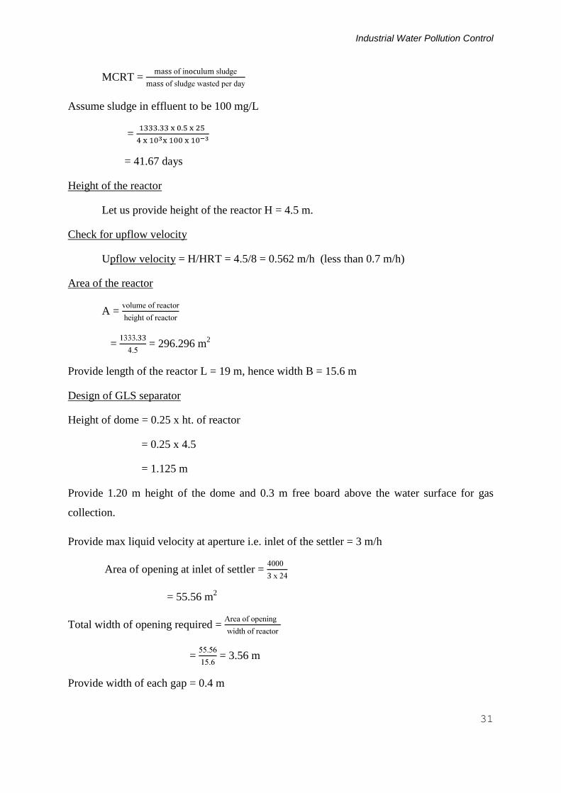
MCRT =
Assume sludge in effluent to be 100 mg/L
=
= 41.67 days
Height of the reactor
Let us provide height of the reactor H = 4.5 m.
Check for upflow velocity
Upflow velocity = H/HRT = 4.5/8 = 0.562 m/h (less than 0.7 m/h)
Area of the reactor
A =
= = 296.296 m2
Provide length of the reactor L = 19 m, hence width B = 15.6 m
Design of GLS separator
Height of dome = 0.25 x ht. of reactor
= 0.25 x 4.5
= 1.125 m
Provide 1.20 m height of the dome and 0.3 m free board above the water surface for gas
collection.
Provide max liquid velocity at aperture i.e. inlet of the settler = 3 m/h
Area of opening at inlet of settler =
= 55.56 m2
Total width of opening required =
= = 3.56 m
Provide width of each gap = 0.4 m
M.M. Ghangrekar, IIT Kharagpur
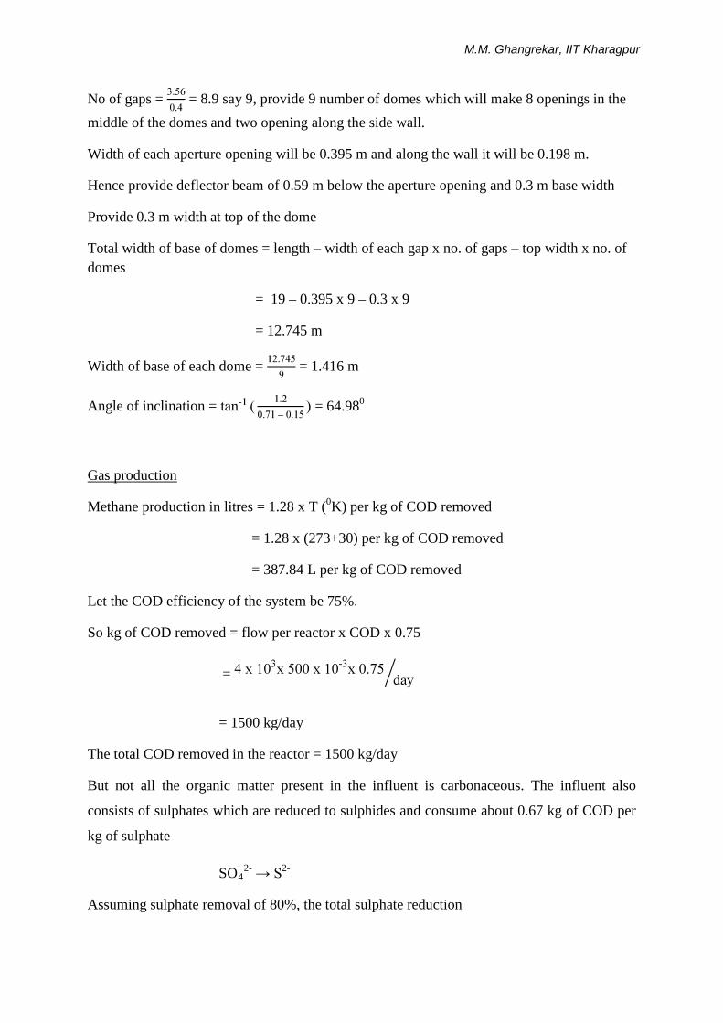
No of gaps = = 8.9 say 9, provide 9 number of domes which will make 8 openings in the middle of the domes and two opening along the side wall.
Width of each aperture opening will be 0.395 m and along the wall it will be 0.198 m.
Hence provide deflector beam of 0.59 m below the aperture opening and 0.3 m base width
Provide 0.3 m width at top of the dome
Total width of base of domes = length – width of each gap x no. of gaps – top width x no. of domes
= 19 – 0.395 x 9 – 0.3 x 9
= 12.745 m
Width of base of each dome = = 1.416 m
Angle of inclination = -–
= 64.980
Gas production
Methane production in litres = 1.28 x T (0K) per kg of COD removed
= 1.28 x (273+30) per kg of COD removed
= 387.84 L per kg of COD removed
Let the COD efficiency of the system be 75%.
So kg of COD removed = flow per reactor x COD x 0.75
= -
= 1500 kg/day
The total COD removed in the reactor = 1500 kg/day
But not all the organic matter present in the influent is carbonaceous. The influent also
consists of sulphates which are reduced to sulphides and consume about 0.67 kg of COD per
kg of sulphate
SO42- → S2-
Assuming sulphate removal of 80%, the total sulphate reduction
Industrial Water Pollution Control
33
= 0.8 x 4000 x 80 x 10-3
= 256 kg/day
COD consumed in sulphate reduction = 256 x 0.67 = 171.52 kg/day
Hence COD available for methane production = 1500 – 171.52 = 1328.48 kg/day
Also some portion of biogas will remain in soluble form in the reactor effluent due to high
partial pressure of biogas inside the reactor. Typically about 16 mg/L of methane will be lost
along with the effluent.
Methane that can be collected = 1328.48 x 0.38 – 4000 x 16 x 10-3 = 440.822 m3/day
Also gas collection efficiency of the domes will be about 85 to 90%, hence actually methane
collected at 85% efficiency will be = 374.69 m3/day
Check for biogas loading at gas-water interface
Total biogas produced assuming methane content to be 70% = = 721 m3/day.
Max gas loading rate = 3 m3/m2/h
Area required =
=
= 10 m2
Total top width =
= = 0.64 m. Hence, the width required for each dome = 0.07 m which is less
than 0.3 m provided.
Check for surface overflow rate (SOR)
Width available in the settling compartment i.e. outside the domes
= (19 – 0.3*9) = 16.3
Hence, SOR = 4000/(16.3*15.6) = 15.73 m3/m2.d (Less than 20 m3/m2.d )
Questions
1. Explain the reaction sequence involved in the anaerobic treatment of wastewater.

M.M. Ghangrekar, IIT Kharagpur
2. Describe different types of bacteria and their role in anaerobic degradation of organic
matter to final end product.
3. Discuss the factors that can affect the anaerobic reactor performance adversely.
4. Describe advantages and disadvantages of anaerobic treatment of liquid waste.
5. Describe different types of reactors used for anaerobic treatment of wastewaters.
6. What is high rate anaerobic process? Name different high rate anaerobic reactors.
7. Explain different types of filters used in anaerobic treatment.
8. With the help of schematic explain UASB reactor and its working.
9. What is GLS separator? What are the design guidelines for GLS separator?
10. Describe advantages of sludge granulation in UASB reactor.
11. Why post treatment is necessary for anaerobic reactor effluents? What post treatment
you will recommend after treatment of sewage in UASB reactor?
12. Describe organic loading rates used for design of UASB reactor. How reactor height
is important for proper functioning of UASB reactor?
13. Design a UASB reactor for treatment of 2 MLD of sewage having COD of 500 mg/L
and BOD of 250 mg/L. Make suitable assumptions for the design.
Answer
Q. 13.
Assume HRT = 8 hr Volume required = 666.67 m3; provide 2 reactors of height of 5.6 m and L x W = 10 x 6 m.


