Company XData Processing UnitSoftware Design Specification
SOFTWARE DESIGN SPECIFICATIONFOR THE
INSTRUMENT XDATA PROCESSING UNIT
FOR THECOMPANY X GAMMA RAY DETECTOR EXPLORER
Document No. DPUSDS-01Rev 2 Chg 0
SEPTEMBER 2001
Project No. XXXXX
DPUSDS-01Rev 2 Chg 0
Page ii

Company XData Processing UnitSoftware Design Specification
SOFTWARE DESIGN SPECIFICATIONFOR THE
INSTRUMENT XDATA PROCESSING UNIT
FOR THECOMPANY X GAMMA RAY DETECTOR EXPLORER
Document No. DPUSDS-01Rev 2 Chg 0
SEPTEMBER 2001
SwRI Project No. XXXX
DPUSDS-01Rev 2 Chg 0
Page iii

Company XData Processing UnitSoftware Design Specification
REVISION NOTICE
Version Identifier Date of Issue Summary of Changes
Rev 0 Chg 0 November 2, 2000 Initial issue containing the architectural-level design representing the Preliminary Design Specification.
Rev 1 Chg 0 February 19, 2001 Initial issue of the complete design, incorporating updates to the architectural design and adding detailed designs for most of the computer software components (CSCs). This is a non-signature version baselined for the DPU Software Design Review (SDR) held on February 21, 2001.
Rev 2 Chg 0 October 2, 2001 Incorporates changes resulting from the SDR, and contains completed designs for those CSCs which were not finished prior to the SDR. In addition, the following design change ECRs are incorporated:eeprm-38: DPU has xMB of EEPROM instead of yMB ssi-40: Changes to SSI hardware design affect driveradc-56: ICU power bus voltage missing from SCM Spectis-60: Changes to TIS from INSTRUMENT X SDRtis-61: TIS_TIME structure is padded by compilerccm-63 – Add HK value for SSI/DCI state machine statustmali-65 – Remove timeout error on tmaliWait()tmali-67 – In correct reporting of queue sizetmali-78 – Frame depth would not be set in Idle modessi-84 – Names of ioctl() commands conflict with DCIedac-94 – Disable SCM EDAC if excessive interrupt
This document contains information that is as complete as possible. Where final numerical values or specification references are not available, best estimates are given and noted TBR (To Be Reviewed). Items which are not yet defined are noted TBD (To Be Determined). The following table summarizes the TBD/TBR items in this revision of the document, and supplements the revision notice above.
Section Description
2.0 The signature status of referenced document 1143-EI-S22904, Spacecraft to Payload Telecommand Interface Control Document was unknown as of the date of this document.
2.0 The document identification number and release status of the Company X On-Board Operational Messaging Interface Control Document was unknown as of the date of this document.
2.0 The release status of Rev 1 Chg 1 of the SCM specification is TBR.
5.16.1.2 The definition of the epoch of the clock message received from the spacecraft is TBD.
DPUSDS-01Rev 2 Chg 0
Page iv

Company XData Processing UnitSoftware Design Specification
TABLE OF CONTENTS
1. Scope............................................................................................................................................................ 11.1 System Overview..................................................................................................................................... 11.2 Document Overview................................................................................................................................. 11.3 Relationship to Other Plans...................................................................................................................... 3
2. Referenced Documents................................................................................................................................. 43. Abbreviations................................................................................................................................................ 74. Software Architecture................................................................................................................................... 9
4.1 Software Design Layers............................................................................................................................ 94.2 Software Components............................................................................................................................. 104.3 Application Software Design Overview..................................................................................................114.4 Execution Model.................................................................................................................................... 124.5 Interrupt Service Routines...................................................................................................................... 164.6 Memory Map.......................................................................................................................................... 184.7 Development Platform............................................................................................................................ 18
5. Software Component Specifications............................................................................................................195.1 Bootstrap CSC........................................................................................................................................ 195.2 Operating System CSC........................................................................................................................... 285.3 Built-In Test CSC................................................................................................................................... 405.4 Error Detection and Correction CSC.......................................................................................................435.5 1553 Driver CSC.................................................................................................................................... 435.6 Generic VME Driver CSC...................................................................................................................... 435.7 Analog to Digital Converter Driver CSC................................................................................................445.8 Synchronous Serial Interface Driver CSC...............................................................................................475.9 Data Capture Interface Driver CSC......................................................................................................... 525.10 EEPROM Driver CSC........................................................................................................................ 565.11 EEPROM File System CSC............................................................................................................... 565.12 Command and Control CSC............................................................................................................... 575.13 Telescope Module Access Library and Interface CSC........................................................................725.14 SCU Interface CSC............................................................................................................................ 835.15 Data Compression CSC...................................................................................................................... 945.16 Time Synchronization CSC................................................................................................................ 995.17 Reserved.......................................................................................................................................... 1035.18 Instrument Control Unit Interface CSC............................................................................................1045.19 Data Processing Algorithm CSC......................................................................................................110
6. Data Dictionary......................................................................................................................................... 120
DPUSDS-01Rev 2 Chg 0
Page v

Company XData Processing UnitSoftware Design Specification
LIST OF TABLES
Table 1. DPU FSW Task Priorities...................................................................................................................... 14Table 2. DPU Interrupt Service Routines............................................................................................................. 17Table 3. Bootstrap CSC Reserved Registers........................................................................................................ 24Table 4. Operating System CSC COTS components............................................................................................28Table 5. Operating System CSC Configurations..................................................................................................28Table 6. Operating System CSC Default Configuration Options..........................................................................29Table 7. DPU Software Module Identifiers.......................................................................................................... 36Table 8. ADC Driver CSC – List of ADC Values................................................................................................44Table 9. ADC Driver CSC Error Numbers...........................................................................................................46Table 10. SSI Driver CSC Device Names............................................................................................................ 48Table 11. SSI Driver CSC ioctl() Commands......................................................................................................49Table 12. SSI Driver CSC Global Data................................................................................................................50Table 13. SSI Driver CSC Error Numbers...........................................................................................................50Table 14. DCI Driver CSC Device Names........................................................................................................... 52Table 15. DCI Driver CSC ioctl() Commands.....................................................................................................53Table 16. DCI Driver CSC Error Numbers..........................................................................................................55Table 17. EEPRM Driver CSC Constants............................................................................................................56Table 18. Hard-Coded DPU Bootup Defaults......................................................................................................58Table 19. DPU Housekeeping Packets................................................................................................................. 60Table 20. DPU Commands.................................................................................................................................. 62Table 21. CCM CSC Global Data........................................................................................................................ 68Table 22. CCM CSC Error Numbers................................................................................................................... 70Table 23. TMALICSC Housekeeping.................................................................................................................. 75Table 24. TMALI CSC Global Data.................................................................................................................... 81Table 25. TMALI CSC Error Numbers................................................................................................................82Table 26. SCUI CSC Global Data....................................................................................................................... 91Table 27. SCUI CSC Error Numbers................................................................................................................... 92Table 28. DCX CSC Global Data........................................................................................................................ 97Table 29. DCX CSC Error Numbers.................................................................................................................... 97Table 30. TIS CSC Global Data........................................................................................................................ 102Table 31. TIS CSC Error Numbers.................................................................................................................... 103Table 32. ICUI CSC Global Data...................................................................................................................... 108Table 33. ICUI CSC Error Numbers.................................................................................................................. 108Table 34. DPA CSC Global Data....................................................................................................................... 118Table 35. DPA CSC Error Numbers................................................................................................................... 119Table 36. Data Dictionary................................................................................................................................. 120
DPUSDS-01Rev 2 Chg 0
Page vi

Company XData Processing UnitSoftware Design Specification
LIST OF FIGURES
Figure 1. DPU Flight Software Layered Architecture............................................................................................9Figure 2. DPU FSW Application Design Diagram...............................................................................................11Figure 3. DPU State Transition Diagram............................................................................................................. 12Figure 4. Task Timing Diagram - One Second Snapshot......................................................................................15Figure 5. Task Timing Diagram - 30 Second Snapshot........................................................................................16Figure 6. Operating System Memory Map........................................................................................................... 18Figure 7. Bootstrap CSC, Flow Chart, Boot Sequence 1......................................................................................20Figure 8. Bootstrap CSC, Flow Chart, Boot Sequence 1 (Continued)...................................................................21Figure 9. Bootstrap CSC, Flow Chart, Boot Sequence 2......................................................................................22Figure 10. Bootstrap CSC, Flow Chart, Bootstrap Monitor Sequence..................................................................23Figure 11. Built-In Tests CSC, Flow Chart, bitPart1() and bitPart2()..................................................................40Figure 12. Built-In Tests CSC, Flow Chart, bitMemOk/bitMemOk32()................................................................41Figure 13. SSI Driver CSC, Call Structure...........................................................................................................47Figure 14. DCI Driver CSC, Call Structure......................................................................................................... 52Figure 15. CCM CSC, Structure Chart, ccmInit().................................................................................................58Figure 16. CCM CSC, Structure Chart, ccmCtrlTask().........................................................................................59Figure 17. CCM CSC, Structure Chart, ccmPerProcess().....................................................................................61Figure 18. CCM CSC, Structure Chart, ccmDefProcess()....................................................................................62Figure 19. CCM CSC, Structure Chart, ccmCmdEnq()........................................................................................64Figure 20. CCM CSC, Structure Chart, ccmCmdTask().......................................................................................65Figure 21. TMALI CSC Normal Event Data Flow...............................................................................................73Figure 22. SCUI CSC, Structure Chart, scuiTask()..............................................................................................84Figure 23. SCUI CSC, Structure Chart, scuiEnq()...............................................................................................85Figure 24. SCUI CSC, Data Package to STPDU Conversion...............................................................................86Figure 25. SCU Interface CSC, Structure Chart, scuiConvertToSTPDU()............................................................87Figure 26. SCU Interface CSC, Flowchart, scuiSTPDUFill()...............................................................................88Figure 27. DCX CSC, Structure Chart, dcxTask()................................................................................................95Figure 28. ICUI CSC, Structure Chart, icuiEnq()................................................................................................105Figure 29. ICUI CSC, Flowchart, icuiEnq().......................................................................................................105Figure 30. ICUI CSC, Structure Chart, icuiCommandReceiveISR()....................................................................106
DPUSDS-01Rev 2 Chg 0
Page vii

Company XData Processing UnitSoftware Design Specification
1. SCOPEThis document specifies the software design for the Company X INSTRUMENT X Data Processing Unit (DPU) Flight Software (FSW). This document specifies a design for the implementation of the software requirements as defined in document DPUSRS-01, Software Requirements Specification for the Instrument X for the Company X Gamma Ray Detector Explorer.
1.1 System OverviewThe Company X observatory is the next in a series of Y medium-class explorer (MIDEX) satellites and is the first-of-its-kind observatory for multi-wavelength transient astronomy. The goal of the Company X mission is to determine the origin of Gamma-Ray Detectors (GRDs) and to exploit data from these detectors to probe the early universe. Company X instrumentation will exploit newly discovered GRD afterglow characteristics to make a comprehensive study of approximately 1000 detectors over its planned three-year mission. Company X will determine the origin of GRDs, reveal how GRD blast waves interact with surroundings, and identify different classes of detectors and associated physical processes. To accomplish these mission goals, Company X employs three semi-autonomous science instruments. The Detector Alert Telescope (DAT) is a wide-angle x -ray telescope that detects GRDs. On detection, the spacecraft slews in the direction of the GRD, bringing it into the view of two narrow-field telescopes for higher-resolution multi-wavelength observation. The narrow-field telescopes are the X-Ray Telescope (XRT), and the Instrument x (INSTRUMENT X).The INSTRUMENT X makes the Company X observatory a complete multi-wavelength facility. Co-aligned with the other instruments, INSTRUMENT X provides simultaneous coverage over a C x C field. The INSTRUMENT X is a powerful complement to the other instruments because of its X capabilities and the absence of atmospheric extinction, diffraction, and background. Since INSTRUMENT X has photon-counting detectors that retain individual photon positions and timing information, it operates in a mode more similar to typical x-ray telescopes than typical optical telescopes. INSTRUMENT X consists of two separate processing units. The Instrument Control Unit (ICU) controls commanding of the telescope. The Data Processing Unit (DPU) handles data collection, processing, and formatting.
The DPU communicates with the ICU through the Synchronous Serial Interface (SSI), and receives raw photon position and timing data from detector electronics through the serial Data Capture Interface (DCI). Because the amount of raw event data that can be collected exceeds the INSTRUMENT X telemetry allocation, the DPU employs histogramming and lossless data compression to reduce the size of its data products. The DPU formats data as Consultative Committee for Space Data Systems (CCSDS) Source Packets, and forwards telemetry to the Spacecraft Control Unit (SCU) through a MIL-STD-1553 (1553) interface. The DPU maintains a local copy of the spacecraft clock to timestamp the telemetry.
1.2 Document OverviewThis Software Design Specification (SDS) describes the structure of the DPU FSW and is intended for use by the software development team. This document specifies the design of the assumes that the reader is familiar with document DPUSDP-01, Software Development Plan for the INSTRUMENT X DPU, and with document DPUSRS-01, Software Requirements Specification for the INSTRUMENT X DPU. The following sections comprise the remainder of this document:
Referenced Documents, Abbreviations, Software Architecture, Software Component Specifications, Data Dictionary, and Appendices.
DPUSDS-01Rev 2 Chg 0
Page 1

Company XData Processing UnitSoftware Design Specification
The Data Dictionary defines abstract data types and data structures for the DPU FSW which are referred to in diagrams and in narrative. In addition to these DPU-unique data types, reference will also be made to basic C language data types and to abstract data types defined by VxWorks® documentation. The definitions for these data types are not repeated in the Data Dictionary. The Data Dictionary contained in this document represents an implementation-specific version of that presented in the SRS. Differences between the Data Dictionary provided in the SRS and the one provided here include:
New data elements identified at design time have been defined in this Data Dictionary. Data elements previously identified in the SRS are repeated in this Data Dictionary, accompanied by implementation details not relevant at requirements definition time. In some cases, names of data elements defined in the SRS have been changed in order to conform to the coding convention.
1.2.1 Document Assumptions and ConventionsThe following sections describe various notations and conventions which are used in this document.
1.2.1.1 Document NumbersThis specification references a number of documents by document number. Not all of those documents have associated document numbers. In those cases, a document number is created for use in this document only, and is annotated in the Referenced Documents section as “for reference in the document only”.
1.2.1.2 Design Method and NotationThe software design notations used in this document are based on the conventions of Structured Analysis and Design. These include Data Flow Diagrams, Flow Charts, and Structure Charts. The following references describe the notation for these diagrams in greater detail.XXXThe notation in this document may vary slightly from published notations. One area in which there is variation is in the labeling of “data couples” on structure charts. In the standard notation, data couples are represented as an unfilled, filled, or partially filled data coupled symbol (O), labeled with the data type or name of the data item being passed. However, the O symbol tends to clutter the diagram without adding much added information. Therefore, structure charts in this document use the following convention:
Parameters passed into a module appear on the left of the call line. Parameters passed back to the calling module appear on the right of the call line. Parameters which are passed in and then modified by the called module appear on both sides of the call line.
1.2.1.3 Consultative Committee for Space Data Systems ConventionsTwo terms, segmented and grouped, exist to describe a collection of CCSDS Source Packets that combine to form a larger single CCSDS Source Packet. This document uses the term segmented whenever referring to these packets. Refer to documents CCSDS 701.0-B-2 and CCSDS 102.0-B-4.
1.2.1.4 Programming LanguageThe document assumes computer software components (CSCs) are implemented in the ANSI C programming language, with the exception of portions of the Bootstrap which are written in PowerPC assembler. Unless otherwise specified, all data and code fragments are shown using the ANSI C notation.
DPUSDS-01Rev 2 Chg 0
Page 2

Company XData Processing UnitSoftware Design Specification
1.2.1.5 Font ConventionsFonts in this document use the following conventions.
This specification contains a Data Dictionary in Section which defines abstract data types for the DPU FSW. References to data types in this specification which are defined in the Data Dictionary are shown in the following font: DATA_ELEMENT. Function names references in sentences will be shown in the following font: functionName(). Source code segments will be shown in the following font: srcCodeSegments.
Parameters to functions will be shown surrounded by angle brackets: <parameter>.
1.3 Relationship to Other PlansThis specification is established in the document DPUSDP-01, Software Development Plan for the INSTRUMENT X DPU. This document specifies the design for development of the DPU FSW, and is driven by the requirements in document DPUSRS-01, Software Requirements Specification for the INSTRUMENT X DPU. The detailed requirements for each CSC are maintained in an electronic spreadsheet to facilitate requirements traceability. Traceability from the design to the requirements is provided in that electronic spreadsheet. Once the detailed designs are complete, a copy of that spreadsheet will be attached to this document as an appendix.
DPUSDS-01Rev 2 Chg 0
Page 3

Company XData Processing UnitSoftware Design Specification
2. REFERENCED DOCUMENTSThe following documents, of the exact issue shown, were referenced as indicated during the development of this SDS. The applicability statement associated with each document reference indicates Superceding if the referenced document supersedes this document in the event of a conflict.
Document ID: DPUICD-01Originator: Company XIssue: Rev 1 Chg 0 (JUNE 2001)Title: Interface Control Document for the ICU/DPU Protocol for the Instrument x.Applicability: Specifies the message-level protocol for DPU/ICU interface. Superseding.
Document ID: DPUSDP-01Originator: Company XIssue: Rev 1 Chg 0 (NOVEMBER 2000)Title: Software Development Plan for the Instrument x Data Processing Unit for the Company
X Gamma Ray Detector Explorer.Applicability: Establishes and identifies this document, and describes the design process used to
produce it.
Document ID: DPUSRS-01Originator: Company XIssue: Rev 1 Chg 0 (APRIL 2001)Title: Software Requirements Specification for the Data Processing Unit for the Company X
Gamma Ray Detector Explorer.Applicability: Specifies the requirements for DPU FSW. Superseding.
Document ID: SCMSPEC-01 (formerly 036911400)Originator: Company XIssue: Rev 1 Chg 1 (MAY 2001) (TBR)Title: Company X Specification for the Company X Communication/Memory Module.Applicability: Specifies the interface to the DPU SCM hardware. Superseding.
Document ID: 1143-EI-S19121Originator: Company YIssue: Rev – (25 AUGUST 2000)Title: Company X 1553 Bus Protocol Interface Control Document.Applicability: Specifies the instrument-generic interface between the remote terminal (RT)
Instruments and the Spacecraft from which software requirements in this document are derived. Superceding.
Document ID: 1143-EI-S22904Originator: Company YIssue: Rev – (06 JUNE 2001) (TBR – not signed)Title: Spacecraft to Payload Telecommand Interface Control DocumentApplicability: Defines the various messages which will be transmitted between the Spacecraft and the
various Instruments.
Document ID: CIDPSDS-01Originator: Company XIssue: Rev 0 Chg 1 (August 1998)Title: Software Design Specification for the Central Instrument Data Processor for the
Instrument Yr for Magnetopause-to-Aurora Global ExplorationApplicability: Specifies the original design of the reuse CSCs from the Instrument W project.
DPUSDS-01Rev 2 Chg 0
Page 4

Company XData Processing UnitSoftware Design Specification
Document ID: 7384-BSPS-01Originator: Company XIssue: Rev 0 Chg 0 (February 1997)Title: Bootstrap Monitor Protocol Specification for Space Station Furnace Facility Control
Units.Applicability: Specifies the Bootstrap Monitor interface for the Bootstrap reuse component.
Document ID: CCSDS 102.0-B-4Originator: Company AIssue: Blue Book (November 1995)Title: Packet TelemetryApplicability: Specifies the CCSDS standard format for Version 1 Source Packets which is referenced
by this document.
Document ID: CCSDS 701.0-B-2Originator: Company AIssue: Blue Book (November 1992)Title: Advanced Orbiting Systems, Networks, and Data Links: Architectural SpecificationApplicability: Specifies the CCSDS standard formats for CCSDS source packets are referenced by this
document.
Document ID: DOC-12067-ZD-00Originator: Company BIssue: March 1997Title: VxWorks® Programmer’s Guide 5.3.1Applicability: Describes VxWorks® real time operating system (RTOS) on which the DPU FSW
executes.
Document ID: DOC-12068-ZD-00Originator: Company BIssue: February 1997Title: VxWorks® Reference Manual 5.3.1Applicability: Describes VxWorks® library functions which are referenced in the design of the DPU
FSW.
Document ID: TBDOriginator: Company CIssue: Version 0.0 (May 30, 2001) (TBR)Title: Company X Onboard Operational Messaging Interface DocumentApplicability: Defines the messages to be transmitted by the Detector Alert Telescope (DAT) and
Figure of Merit (FoM), and which describes the concept of operations for the Company X observatory.
Document ID: POWER-ARCH (for reference in the document only)Originator: Company DIssue: Version 1.53 (July 22, 1991)Title: POWER Processor ArchitectureApplicability: Contains the procedure for accessing the RSC-VME processor board Real-Time Clock.
Document ID: XMM-OM/Originator: University AIssue: 0004.03 (1991)Title: DPU Processing for XMM/OM – Tracking and Compression AlgorithmApplicability: Describes the data compression and science algorithms used on the XMM-OM mission,
which are being reused in the DPU FSW design.
DPUSDS-01Rev 2 Chg 0
Page 5

Company XData Processing UnitSoftware Design Specification
3. ABBREVIATIONSsecs MicrosecondsAOS Advanced Orbital SystemsDAT Detector Alert TelescopeBIT Built-In TestC&DH Command and Data Handling SystemCCSDS Consultative Committee for Space Data SystemsCIDP Central Instrument Data ProcessorCOTS Commercial Off-The-ShelfCPU Central Processing UnitCSC Computer Software ComponentCSCI Computer Software Configuration ItemCTS Clear-To-SendDMA Direct Memory AccessdosFs Disk Operating System FilesystemDPU Data Processing UnitDRAM Dynamic Random Access MemoryEDAC Error Detection And CorrectionEEPROM Electrically Erasable Programmable Read-Only MemoryFSW Flight SoftwareGRD Gamma Ray DetectorGSE Ground Support EquipmentGSW Ground SoftwareI/O Input/OutputICD Interface Control DocumentICU Instrument Control UnitKb Kilo-bits (1024 bits)kbps Kilo-bits per secondKB Kilo-bytes (1024 bytes)mbps Mega-bits per secondMB Mega-bytes (1,048,576 bytes)MET Mission Elapsed Timemsecs MillisecondsOFP Operational Flight ProgramPROM Programmable Read-Only MemoryRBI RSC Bus InterfaceRCPUM RAD6000 CPU ModuleRSC Rios Single ChipRT Remote Terminal; (1553 term for a science instrument on the 1553 bus)SCM Company X Communications ModuleSCU Spacecraft Control UnitSDP Software Development PlanSRS Software Requirements SpecificationSVP Software Verification Procedures
DPUSDS-01Rev 2 Chg 0
Page 6

Company XData Processing UnitSoftware Design Specification
XRT X-Ray Telescope
DPUSDS-01Rev 2 Chg 0
Page 7

Company XData Processing UnitSoftware Design Specification
4. SOFTWARE ARCHITECTUREThe following sections specify the architectural design of the INSTRUMENT X DPU FSW. The architectural design consists of
an overview of the software layers, a list of the CSCs comprising the DPU FSW, an overall application design diagram, a description of the execution model and operating states, a top-level memory map, and a description of the development platform, language, and compiler.
This document assumes that the reader is familiar with document DPUSRS-01, Software Requirements Specification for the INSTRUMENT X DPU. Refer to Section 4 of that document for an overview of the operational concepts, goals, and constraints of the DPU FSW.
4.1 Software Design LayersThe design of the DPU FSW is modular and layered. Modularity provides for data hiding, helps facilitate software reuse, and supports incremental testing. The DPU FSW consists of two layers: the System Software layer and the Application Software layer. The Application Software layer consists of the Application Framework Software and the Science Data Processing Software. The System Software layer hides the details of the hardware interfaces from the Application Software layer. The Application Framework Software implements application-level data protocols on top of the lower-level device drivers contained in the System Software Layer. The Science Data Processing Software retrieves data from, and transmits data to the Application Framework Software via an application programming interface (API). The architecture of the DPU FSW is illustrated in Figure 1.
Figure 1. DPU Flight Software Layered Architecture
DPUSDS-01Rev 2 Chg 0
Page 8

Company XData Processing UnitSoftware Design Specification
4.2 Software ComponentsThe DPU FSW is composed of two Computer Software Configuration Items (CSCIs):
DPUFSW-01 – DPU System Software DPUFSW-02 – DPU Application Software
Each of these CSCIs is composed of computer software components (CSCs). The SDP and SRS contain lists of CSCs which comprise the DPU FSW. However, additional CSCs are typically identified at design time which are not identified nor relevant during the requirements analysis phase. Therefore, the list of CSCs in the following sections describe some CSCs not included in the list in the SDP or SRS.Many of these CSCs are components being reused from the Central Instrument Data Processor (CIDP) on the imager for INSTRUMENT Y project. The original design for these CSCs are described in document CIDPSDS-01, Software Design Specification for the INSTRUMENT Y CIDP.
4.2.1 System Software CSCIThe Bootstrap is a PROM-resident program which performs a basic hardware built-in-test, loads the DPU FSW from EEPROM, and provides a simple RS-232-based monitor useful during development for examining memory and for downloading programs.The Operating System (RTOS) CSC provides a real-time, multi-tasking environment. The Operating System is a COTS product, identified as VxWorks 5.3, kernel version WIND 2.5. The Operating System CSC is supplemented with a library of miscellaneous project-specific system utilities.The Built-In Tests (BIT) CSC provides a set of functions to perform and record the results of memory and interface tests on the hardware modules included in the DPU.The Error Detection and Correction (EDAC) CSC provides a set of functions to facilitate the tracking, handling, and recording of memory errors.The MIL-STD-1553B Driver (1553) CSC provides an application interface to the MIL-STD-1553B data bus hardware on the SCM.The Generic VME (GVME) Driver provides a library of utility routines useful in accessing the memory and register residing in the VME memory space.The Analog-To-Digital Converter (ADC) Driver provides an application interface to the analog-to-digital converter hardware on the SCM.The Synchronous Serial Interface Driver (SSI) CSC provides an application interface to the SSI interface hardware on the SCM.The Data Capture Interface (DCI) Driver provides an application interface to the DCI interface hardware on the SCM.The EEPROM Interface Driver (EEPRM) CSC provides an application interface to the EEPROM on the Company X Communication/Memory Module (SCM).The EEPROM File System (EEFS) CSC provides a file system which is media-compatible with MS-DOS. The file system facilitates dynamic loading of application programs using the VxWorks loader, as well as storage for any data files which are needed by the application program.
4.2.2 Application Software CSCIThe Command and Control (CCM) CSC is an application program that performs the core control functions for the DPU. This CSC initializes the DPU FSW, establishes and maintains the current system state, dispatches commands received from the ICU and the Spacecraft, collects housekeeping telemetry, schedules periodic processing tasks such as heartbeats, monitors the execution of other DPU FSW tasks, handles memory loads and dumps, and is responsible for overall error handling.
DPUSDS-01Rev 2 Chg 0
Page 9

Company XData Processing UnitSoftware Design Specification
The Telescope Module Access Library and Interface (TMALI) CSC is an application program that handles the transfer of raw events from the DCI interface via the DCI driver, and makes these events available to the Data Processing Algorithms CSC.The Spacecraft Control Unit Interface (SCUI) CSC is an application program which manages communications with the SCU over the 1553 interface at the application data protocol level.The Data Compression Algorithm (DCX) CSC is an application program that compresses the science and engineering data products produced by the Data Processing Algorithm CSC.The Time Synchronization (TIS) CSC is an application program which maintains time synchronization with the spacecraft clock, and which provides access to the DPU clock via an API.The Instrument Control Unit Interface (ICUI) CSC is an application program that manages communications with the ICU over the SSI interface at the application data protocol level.The Data Processing Algorithms (DPA) CSC is an application program that receives and processes INSTRUMENT X detector events, and produces science and engineering data products.
4.3 Application Software Design OverviewThe following diagram illustrates the overall application software design and the interrelationships between the various application layer CSCs. The Time Synchronization CSC is not shown to avoid cluttering the diagram.
SpacecraftInterface CSC
InstrumentControl Unit
Interface CSC
Data CompressionCSC
Data ProcessingAlgorithms CSC
Telescope ModuleInterface CSC
DetectorEvents
DetectorEvents
FIFO
DetectorEvents
Science andEngineering
Data
CompressedData
HousekeepingData
TelemetryPackets
TelecommandPackets 1
Command andControl CSC
Time MsgMemory
Load
DPUCommands
TelecommandPackets
State ofHealth
TelemetryPackets
Control andStatusReturn
Control andStatusReturn
Control andStatusReturn
Science & Housekeeping Flow
Command & State of Health Flow
Internal Control & Status Flow
Reuse New
Figure 2. DPU FSW Application Design Diagram
DPUSDS-01Rev 2 Chg 0
Page 10

Company XData Processing UnitSoftware Design Specification
4.4 Execution ModelThe DPU FSW executes on top of a real-time operating system, VxWorks™. The DPU FSW is both multi-tasking and interrupt-driven and consists of multiple prioritized tasks. Tasks are triggered in one of four ways:
by semaphore wake-up given by an interrupt service routine (ISR), by semaphore wake-up given by another software task, by scheduler wake-up due to a higher priority task becoming ready, or due to a higher priority task being blocked on some event allowing a lower priority task to run.
The following sections describe the DPU FSW startup sequence, operational states, and the tasks comprising the DPU FSW.
4.4.1 Startup SequenceThe DPU FSW is booted using PROM-resident bootstrap software. The bootstrap software performs a basic set of built-in tests, then copies the DPU FSW from EEPROM to DRAM and executes it. In flight, there are two methods which can trigger the DPU FSW to boot:
power-on (cold boot), or watchdog reset (warm boot, commanded reboot).
On flight, a power cycle can only be effected by the SCU. A watchdog reset could be induced by the DPU FSW due to a detected, unrecoverable error, or it could occur as a by-product of the FSW entering a state in which it fails to strobe the watchdog timer. On boot, the bootstrap tests and clears DRAM, and then proceeds to load the DPU FSW from EEPROM and executes it. The DPU FSW then loads configuration information from EEPROM (which establishes various operational defaults) and spawns the various DPU FSW tasks.
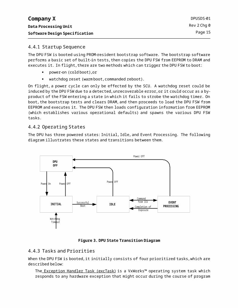
4.4.2 Operating StatesThe DPU has three powered states: Initial, Idle, and Event Processing. The following diagram illustrates these states and transitions between them.
INITIAL IDLESuccessfulBoot
Commandfrom ICU
DPUOFF
Power OnPower Off
WatchdogTimeout
Power Off
Completion of Exposure
Power Off
EVENTPROCESSING
Figure 3. DPU State Transition Diagram
DPUSDS-01Rev 2 Chg 0
Page 11

Company XData Processing UnitSoftware Design Specification
4.4.3 Tasks and PrioritiesWhen the DPU FSW is booted, it initially consists of four prioritized tasks, which are described below:
The Exception Handler Task (excTask) is a VxWorks™ operating system task which responds to any hardware exception that might occur during the course of program execution. If an exception occurs, the Exception Handler suspends the offending task. The Exception Handler is customized such that if an unrecoverable exception occurs, it will attempt to record the cause of the exception to EEPROM and reboot the DPU by disabling the watchdog strobe. Conditions which could trigger an exception include a multiple-bit memory error or a data storage error.The Command and Control Task (ccmCtrlTask) is an Application Framework Software task which is responsible for spawning the remaining DPU FSW tasks and initializing the DPU FSW. After spawning the other FSW tasks, the Command and Control Task then remains active to perform the remaining periodic processing tasks such as housekeeping collection and overall DPU FSW monitoring. In addition, it facilitates memory loads and dumps, and serves as the central point for error reporting.The Log Task (logTask) is a VxWorks™ operating system task which is used to log program output during software development and ground integration and test (I&T). The task is left in the flight build in order to avoid different builds for ground testing vs. on orbit operations. The task sits idle during on orbit operations.The Shell Task (shell) is a VxWorks™ operating system task which provides a command-line interface to the DPU FSW during software development and ground I&T. The task is left in the flight build in order to avoid different builds for ground testing vs. on orbit operations. The task normally sits idle during on orbit operations. However, it is possible to invoke the shell on orbit by way of a special ground command in the event it is necessary to diagnose an off-nominal condition or to install a software patch.
Following startup, the Command and Control Task spawns the remaining DPU FSW tasks, which are described below:
The Command Dispatch Task (ccmCmdTask) is an Application Framework Software task which is responsible for dispatching commands which arrive from the ICU or the SCU. Commands are executed directly by this task by calling the applicable CSC function. Commands which consume more than 10 milliseconds to execute must be executed in a deferred fashion by a task associated with the applicable CSC (e.g. memory dumps, mode commands, etc.).The SCU Interface Task (scuiDPTask) receives telemetry data from other tasks, converts them to CCSDS Version 1 Source Packets, forms Company X Telemetry Protocol Data Units (STPDUs) from the Source Packets, and transmits the STPDUs to the SCU via the MIL-STD-1553B Interface.The Telescope Module Event Transfer Task (tmaliTask) is an Application Framework Software task which is responsible for transferring data from the DCI ping/pong buffers to the TMALI data buffer in response to a DCI frame limit or data timeout interrupt.The Data Compression Task (dcxTask) receives telemetry data from other tasks, uses a lossless data compression algorithm to compress the data, and then enqueues the data to the SCU Interface Task.The Data Processing Algorithms Tasks (dpaIMTask and dpaEPTask) process incoming detector events according to the commanded mode, create data products, and enqueue those data products to the Data Compression Task (if compression is enabled) or to the SCU Interface Task.The Error Detection and Correction Memory Scrubber Task (edacTask) cycles through the text and data segments of the DPU to trigger the correction of single-bit errors which may have occurred, in order to help prevent the occurrence of uncorrectable multiple-bit errors.
DPUSDS-01Rev 2 Chg 0
Page 12

Company XData Processing UnitSoftware Design Specification
The priority scheme for the DPU FSW tasks is shown in the following table, along with an indication of how each task is awakened. The priority number listed in the table represents relative (rather than absolute) priority, with a lower number indicating a higher priority.
Table 1. DPU FSW Task Priorities
Task NameRel. Task Priority Priority Rationale
Task Awakened On/Expected Frequency
excTask 1 This task must be the highest priority task since it is the exception handler for the operating system.
Trigger: Exception
Frequency: Nominally idle
ccmCmdTask 2 This task is responsible for dispatching commands received from the ICU or the SCU. Commands arrive via interrupt, and are enqueued into a FIFO managed by this task. This task priority is higher than other tasks in order to ensure that commands are executed as quickly as possible after receipt, and so that if another task goes awry that the DPU can be effectively commanded..
Trigger: Semaphore given in an ISR following arrival of command from the ICU or SCU.
Frequency: Asynchronous
scuiTask 3 This task handles end-to-end communication with the S/C. The S/C wakes this task up nominally every 111 ms. This task must run when scheduled in order to prevent data loss due to overrunning its buffer and in order to help ensure synchronization is maintained with the spacecraft.
Trigger: Semaphore given in an ISR following write to “Done” Subaddress by the SCU.
Frequency: x Hz
tmaliTask 4 This task transfers events from the DCI shared memory to the event queue contained in the RAD6000 DRAM.
Trigger: Semaphore given in an ISR in response to a DCI ping/pong or data timeout interrupt.
Frequency: x Hz during an observation
ccmCtrlTask 5 On bootup, this task initializes the DPU FSW on bootup and spawns other tasks. Once completed, the task then handles periodic processing (such as watchdog strobing, sending the heartbeat to the ICU) and collection of housekeeping. This task also handles memory dumps. This task awakens on a periodic basis and must be higher than the data processing algorithm (DPA) tasks since the DPA tasks could starve this task.
Trigger: Semaphore following arrival of the clock message from the SCU.
Frequency: x Hz
edacTask 6 The edacTask scrubs memory looking for SBEs and MBEs. This task may safely run at this relatively high priority because it is self-limiting. If set a priority lower than the DPA tasks, the edacTask could get starved. The spawn options for this task are set such that it consumes a very small portion of the total CPU time.
Trigger: Task delay timer
Frequency: x Hz
dpaIMTask 7 The dpaIMTask is responsible for performing drift correction, and creating data products which include Instrument Ys and the Parameterized Finding Chart. This task must be allowed to complete its work prior to resuming event processing and so is set at a higher priority than the event processor task.
Trigger: Availability of data for processing.
Frequency: x Hz if tracking
dpaEPTask 8 dpaEPTask is responsible for reading data from the TMALI event buffer, applying Instrument Y and Event filters, accumulating Instrument Y histograms, and writing events to the DCX FIFO. This task is set at a lower priority because it could potentially consume all available CPU cycles.
Trigger: Availability of events for processing.
Frequency: Data and mode dependent; nominal x Hz during observations
dcxTask 9 This task is responsible for compressing data and forwarding it to scuiTask. The priority for this task was assigned a low value to ensure that it consumes any CPU time remaining after the DPA tasks have completed event processing.
Trigger: Availability of data for compression.
Frequency: Data and mode dependent; nominal 10Hz during science observations
DPUSDS-01Rev 2 Chg 0
Page 13

Company XData Processing UnitSoftware Design Specification
Table 1. DPU FSW Task Priorities
Task NameRel. Task Priority Priority Rationale
Task Awakened On/Expected Frequency
shellTask 10 This task executes shell commands which are entered via the serial interface during ground I&T, or via special ground command on orbit. The priority of this task is set low to avoid any possibility of the task consuming the CPU for some reason. Because the command handler task (ccmCmdTask) are higher priority than other tasks, commands can be issued to suspend any rogue tasks if necessary to facilitate the execution of a shell command even with such a lower priority for the shellTask.
Trigger: Execution of a shell command.
Frequency: Nominally idle
logTask 11 This task is idle on orbit. Trigger: Execution of a logMsg() output.
Frequency: Idle
The following timing diagram represents a one second snapshot of time and provides a detailed look at the multi-tasking activity performed by the DPU FSW. In this illustration, the DPU is in the middle of the “10 second filter fan” phase of a GRD observation. The dotted lines connecting the tmaliTask instantiations to the dpaEPTask instantiations illustrate that the dpaEPTask is awakened as a result of new events being transferred into the queue and made available for processing by the tmaliTask.
dpaIMTask
ccmCmdTask
scuiTask
tmaliTask
dpaEPTask
dcxTask
2 msec
12 msec
6.5 msec
ccmPPTask
10 msec
Figure 4. Task Timing Diagram - One Second Snapshot
DPUSDS-01Rev 2 Chg 0
Page 14

Company XData Processing UnitSoftware Design Specification
The following timing diagram represents a second snapshot of time and provides a higher-level look the multi-tasking activity performed by the DPU FSW. In this illustration, the DPU is in the middle of the “100 (or 1000) second filter fan” phase of a GRD observation.
dpaIMTask
dpaEPTask
dcxTask
ccmPPTask
Figure 5. Task Timing Diagram - 30 Second Snapshot
4.5 Interrupt Service RoutinesThe DPU has five types of external (VME) interrupts:
MIL-STD-1553 Interface Interrupts, DCI Interface Interrupts, SSI Interface Interrupts, Memory EDAC Interrupt, and Ethernet Interrupt (ground use only).
The DPU responds to interrupts via an interrupt service routine (ISR). VME interrupts are prioritized; however the DPU does not allow nested interrupts, and so any interrupts which occur while servicing another interrupt will pend until the current ISR has returned. The following table lists each ISR, which VME interrupt it corresponds to, and what action the ISR takes in response to the interrupt. The interrupts are listed in priority order, with the highest priority interrupt listed first (a higher interrupt request (IRQ) number indicates a higher priority). For clarity, the table includes the response of the DPU to a RAD6000 DRAM memory error exception along with the IRQ 7 ISR, even though a RAD6000 EDAC exception is not technically an external interrupt.
DPUSDS-01Rev 2 Chg 0
Page 15

Company XData Processing UnitSoftware Design Specification
Table 2. DPU Interrupt Service Routines
Interface and VME IRQ
Interrupt Service Routine
Cause(s) Response(s)
Memory EDAC
IRQ 7
Memory Error Interrupt ISR
EDAC error in RAD6000 DRAM Address of error and error counter captured for housekeeping.
Single bit errors are scrubbed.
Multiple bit errors result in EDAC HK being written to EEPROM and the DPU reboots.
EDAC error in PROM or EEPROM Address of error and error counter captured for housekeeping.
Single bit errors are scrubbed.
Multiple bit errors are reported in HK for ground intervention.
MIL-STD-1553
IRQ 6
Spacecraft Command Response ISR
Clock Message arrival from the SCU New time written to hardware latch register.
UT Delta saved in static memory.
Semaphore given to awaken Periodic Processing Task.
ACS Message arrival from the SCU ACS Message copied to science data (transient phase only).
DPU Command arrival from the SCU Command enqueued into CCM Command Dispatch Task.
Obs. Message arrival from the SCU Messages discarded/ignored.
Telemetry “Done” ISR
SCU has completed reading prior ST_PDU and has written acknowledgement to the “Done” subaddress.
Semaphore given to awaken the SCU Interface Task.
SSI Interface
IRQ 5
ICU Command Response ISR
DPU Command arrival from the ICU Command enqueued into CCM Command Dispatch Task.
DCI Interface
IRQ 4
DCI Event Transfer ISR
DCI ping/pong buffer reaches its frame limit
Semaphore given to awaken the TMALI Event Transfer Task.
DCI ping/pong buffer has stale events waiting.
Semaphore given to awaken the TMALI Event Transfer Task.
DCI Error ISR
The DPU FSW has failed to finish transferring the prior event data set and re-arm the ping/pong prior to another frame limit.
Housekeeping error counter is incremented.
Error recovery flag is set for handling by the TMALI Event Transfer Task.
Semaphore given to awaken the TMALI Event Transfer Task.
IRQ 3 Unused
Ethernet Interface
IRQ 2Ethernet Driver
Ground use only.
IRQ 1 Unused
DPUSDS-01Rev 2 Chg 0
Page 16

Company XData Processing UnitSoftware Design Specification
4.6 Memory MapThe memory map for the RAD6000 DRAM is shown in the figure below. For additional detail refer to document DOC-12067-ZD-00, VxWorks® Programmer’s Guide 5.3.1.
Data Segment
Interrupt Vector Table
Page Frame Tableand
Hash Allocation Table
Text Segment
COLD_MEM_SIZEWARM_MEM_SIZE sysMemTop
Figure 6. Operating System Memory Map
The memory map for the SCM-resident EEPROM is provided in Appendix B of document DPUSRS-01, Software Requirements Specification for the INSTRUMENT X DPU. The memory map for the various VME interface devices is provided in document 036911400
4.7 Development PlatformThe DPU FSW will be implemented in the ANSI C programming language, with some PowerPC assembly used in the Bootstrap and to implement the VME data transfer in the DCI Driver. The host (development) platform and operating system is Sun/Solaris™ from Sun Microsystems, Inc. The target platform is the RAD6000 processor which has a POWER (PowerPC-like) architecture, and executes the VxWorks™ 5.3.1 real-time operating system. The cross compiler and debugger is MULTI/C/C++ 1.8.9 from Green Hills Software, Inc. Refer to document DPUSDP-01, Software Development Plan, for additional detail regarding the development toolset and environment.
DPUSDS-01Rev 2 Chg 0
Page 17

Company XData Processing UnitSoftware Design Specification
5. SOFTWARE COMPONENT SPECIFICATIONSThe following sections describe the detailed design for each of the DPU FSW CSCs.
5.1 Bootstrap CSCThe Bootstrap CSC is a Level 1 reuse component from the SSFF and INSTRUMENT Y projects. The design of the INSTRUMENT Y Bootstrap is described in document CIDPSDS-01. The Bootstrap for the Company X DPU will be nearly identical to that used on the INSTRUMENT Y CIDP and SCU, with the exception of minor hardware interface differences:
The interface to the hardware watchdog timer is different on the Company X DPU versus that used on the INSTRUMENT Y CIDP/SCU. The interface to the mission elapsed time (MET) clock is different on the Company X DPU versus that used on the INSTRUMENT Y CIDP/SCU. The INSTRUMENT Y bootstrap was able to discern a cold (power-on) boot from a warm (watchdog reset) boot by examining the value of the MET clock, which did not reset to zero on a warm boot. The Company X DPU MET clock resets to zero on both a cold and warm boot, and so there is no distinction in the Company X bootstrap.
The detailed design for these changes in the Bootstrap CSC is shown in the following flow charts.Figure 7 and Figure 8 show the initial boot sequence, identified as Boot Sequence 1. This processing takes place when the Bootstrap executes from Programmable Read-Only Memory (PROM). Boot Sequence 1 is composed primarily of 4 steps as follows.First, in this sequence, EEPROM is updated. Then, CPU BIT and a portion of DRAM BIT is performed. Next, DRAM is cleared. Lastly, Boot Sequence 2 is copied to DRAM and executed.Figure 9 shows the second boot sequence, identified as Boot Sequence 2. During this sequence, the rest of DRAM is tested if skipBit is not set. Load parameters are put into registers r13, r14, r15 and r16. DRAM is cleared up to memSize. Lastly, either the DPU-RTOS or the Bootstrap Monitor is loaded and executed according to the load parameters.Figure 10 shows the Bootstrap Monitor processing. The user interface to the Bootstrap Monitor is described in document 7384-BSPS-01.
DPUSDS-01Rev 2 Chg 0
Page 18
Company XData Processing UnitSoftware Design Specification
Figure 7. Bootstrap CSC, Flow Chart, Boot Sequence 1
DPUSDS-01Rev 2 Chg 0
Page 19

Company XData Processing UnitSoftware Design Specification
Figure 8. Bootstrap CSC, Flow Chart, Boot Sequence 1 (Continued)
DPUSDS-01Rev 2 Chg 0
Page 20

Company XData Processing UnitSoftware Design Specification
Figure 9. Bootstrap CSC, Flow Chart, Boot Sequence 2
DPUSDS-01Rev 2 Chg 0
Page 21

Company XData Processing UnitSoftware Design Specification
Figure 10. Bootstrap CSC, Flow Chart, Bootstrap Monitor Sequence
DPUSDS-01Rev 2 Chg 0
Page 22

Company XData Processing UnitSoftware Design Specification
5.1.1.1 Reserved RegistersReserved registers facilitate passing data between portions of the Bootstrap. These are described in the following table.
Table 3. Bootstrap CSC Reserved Registers
Register Description
General Purpose Register 13 Start of Program in EEPROM
General Purpose Register 14 End of Program in EEPROM
General Purpose Register 15 Copy Point in DRAM
General Purpose Register 16 Entry Point in DRAM
General Purpose Register 17 MEM_SIZE
General Purpose Register 18 Load Program Indicator
General Purpose Register 19 GPR Test Failed Indicator
General Purpose Register 20 Ram Test 1 Failed Indicator
General Purpose Register 21 System Block Base Address
Segment Register 0 DRAM access
Segment Register 1 Scratch (ISRs)
Segment Register 2 Scratch (ISRs)
Segment Register 3 VME Bus 32-Bit access
Segment Register 4 SRR0 from last interrupt
Segment Register 5 SRR1 from last interrupt
Segment Register 6 DAR from last interrupt
Segment Register 7 DSISR from last interrupt
Segment Register 9 Bootstrap Monitor Configurable
Segment Register 10 VME Bus 8-bit access
Segment Register 11 VME Bus 32-Bit access
Segment Register 12 VME Bus 16-Bit access
Segment Register 13 External Interrupt Control Registers access
Segment Register 14 Input/Output Channel Controller access
Segment Register 15 SUROM access
Condition Register bit 13 Autoboot Indicator
0: No AutoBoot1: AutoBoot
Condition Register bit 14 Lockup Bit
Values:
0: Do not exit the Bootstrap Monitor1: Exit the Bootstrap Monitopr if the timeout expires
Condition Register bit 15 Boot Configuration Index
0: BC01: BC1
Condition Register bit 16 Decrementer Interrupt Indicator
Values:
0: Decrementer Interrupt has not occurred1: Decrementer Interrupt has occurred
DPUSDS-01Rev 2 Chg 0
Page 23

Company XData Processing UnitSoftware Design Specification
Table 3. Bootstrap CSC Reserved Registers
Register Description
Condition Register bit 17 SBE Indicator
Values:
0: No SBEs have occurred1: An SBE has occurred
Condition Register bit 18 Skip Built-In Tests
Values:
0: Perform BIT1: Skip BIT
Condition Register bit 19 Program Load
Values:
0: Do not load program1: Load program according to registers GPR 13, GPR 14, GPR 15, and GPR 16
Condition Register bit 20 Warm Boot Indicator
Values:
0: Boot is Power/On1: Boot is a VME Reset (Reboot)
Condition Register bit 21 System Block Checksum Failed
Values:
0: The System Block checksum is valid1: The System Block is corrupt or checksum is not valid
Condition Register bit 22 CPU Test Failed Indicator
Values:
0: The CPU test passed1: The CPU test failed
Condition Register bit 23 RAM Test 1 Failed Indicator
Values:
0: The RAM Test 1 passed1: The RAM Test 1 failed
Condition Register bit 24 RAM Test 2 Failed Indicator
Values:
0: The RAM Test 2 passed1: The RAM Test 2 failed
Condition Register bit 25 Machine Check Interrupt Indicator
Values:
0: A Machine Check Interrupt has not occurred1: A Machine Check Interrupt has occurred
Condition Register bit 26 Data Storage Interrupt Indicator
Values:
0: A Data Storage Interrupt has not occurred1: A Data Storage Interrupt has occurred
Condition Register bit 27 Instruction Storage Interrupt Indicator
Values:
0: A Instruction Storage Interrupt has not occurred1: A Instruction Storage Interrupt has occurred
DPUSDS-01Rev 2 Chg 0
Page 24

Company XData Processing UnitSoftware Design Specification
Table 3. Bootstrap CSC Reserved Registers
Register Description
Condition Register bit 28 External Interrupt Indicator
Values:
0: A External Interrupt has not occurred1: A External Interrupt has occurred
Condition Register bit 29 Alignment Interrupt Indicator
Values:
0: An Alignment Interrupt has not occurred1: An Alignment Interrupt has occurred
Condition Register bit 30 Program Interrupt Indicator
Values:
0: A Program Interrupt has not occurred1: A Program Interrupt has occurred
Condition Register bit 31 Floating-Point Unavailable Interrupt Indicator
Values:
0: A Data Storage Interrupt has not occurred1: A Data Storage Interrupt has occurred
5.1.2 Stage 1 Built-In TestThere are two stages of Built-In Tests (BIT) for the DPU. The Stage 1 BIT is included in the Bootstrap program and consists of Central Processing Unit (CPU) BIT, and Dynamic Random Access Memory (DRAM) BIT. The Stage 2 BIT is executed after the operating system is booted and is not part of the Bootstrap program.
5.1.2.1 CPU BITThe CPU BIT consists of a series of tests designed to test each of the functional units of the processor. These include test for the Branch-Unit, the Fixed-Point Unit, the Floating-Point Unit, the Interrupt-Unit, and the Timer Unit. Each of these tests consists of executing a few selected instructions from the this functional unit.The General Purpose Registers (GPR), the Segment Registers (SR), the Counter Register (CTR), and the Condition Register are tested for stuck-bits as part of the Branch-Unit test. This is done by writing a 1’s pattern (verified by reading it back) and then writing a 0’s pattern (verified by reading it back).
5.1.2.2 DRAM BITPart of the memory is tested in Boot Sequence 1, and part of the memory is tested during Boot Sequence 2. During Boot Sequence 1, X KB of DRAM is tested before the Bootstrap is copied to this area. During Boot Sequence 2, the remaining memory is tested in ? KB blocks.The DRAM BIT first writes the address of each word in a block to that word in the block. Then the test flushes the cache and reads back the entire block. If a single-bit error occurs on the read-back, the location is read again. If another single-bit error occurs, the test assumes a hard error and marks the whole block bad. If a multiple-bit error occurs, the whole block is marked bad. If the value read back does not match the address, the whole block is marked bad. This same process is repeated with the one’s complement of the address.The Bootstrap stores the results of the DRAM BIT in EEPROM as a series of x consecutive y-bit words. Each bit in a result word represents the result of testing a X KB block of DRAM. These bits are mapped to DRAM by proceeding from least-significant bit (LSb) to most-significant bit (MSb) as the addresses of the memory blocks increase. A set bit indicates that a block of DRAM has failed. A clear bit indicates that a block of DRAM has passed the test.
DPUSDS-01Rev 2 Chg 0
Page 25

Company XData Processing UnitSoftware Design Specification
5.1.3 Hardware InterfacesThe DPU-BOOTSTRAP must interface directly with the EEPROM on the Company X Communication Module. The DPU-BOOTSTRAP accesses EEPROM as X-bit words only. The specific timing requirements of the EEPROM are satisfied in one of three ways:
the timing requirements are met by inserting specific wait loops (typical), the timing requirements are met by use of the EEPROM Driver (DOWNLOAD command), and the timing requirements are met implicitly by the amount of time which will be required to execute
the intervening instructions regardless of the CPU speed setting (DRAM test logic).
5.1.4 Error RecoveryThis section describes the error recovery mechanisms of the DPU-BOOTSTRAP.
5.1.4.1 Hardware ExceptionsThe Bootstrap ignores any hardware exceptions that might occur while it is running. If an exception occurs, the Bootstrap simply resumes execution with the next instruction following the one at which the exception occurred.
5.1.4.2 Bootstrap MonitorThe Bootstrap Monitor checks entered commands for syntax and number of arguments, and displays an error message to the RS-232 interface if an invalid command or argument is entered. A complete listing of these messages is given in document BSPS-01.
DPUSDS-01Rev 2 Chg 0
Page 26

Company XData Processing UnitSoftware Design Specification
5.2 Operating System CSCThe Operating System CSC, DPU-RTOS, provides a real-time, multi-tasking environment. The Operating System CSC is a COTS product, identified as VxWorks 5.3.1, kernel version WIND 2.5. The Operating System CSC is supplemented with a library of miscellaneous project-specific system utilities. The following sections list and describe the modifications to the COTS configuration files, as well as the design of added custom utilities.
5.2.1 Product IdentificationVxWorks® consists of the following COTS components:
Table 4. Operating System CSC COTS components
Product Name ES Product VxWorks®: Solaris/RAD 6000
Release 5.3.1 (Tornado 1.0.1 FCS 2)
Part Number 100-8044-1C-30
Serial Number
License Number 105078
Vendor
5.2.2 Operating System ConfigurationsThe DPU includes two configurations of the DPU-RTOS. These are described in the following table.
Table 5. Operating System CSC Configurations
Identifier Boot Parameters Description
DPU-BC0 Location: cmmBase32 + 0x400014
Instrument Y Size: less than 512 KB
Boot Configuration 0
Complete FSW build in compressed format.Hardware-strapped read-only without external write-enable plug.
DPU-BC1 Location: cmmBase32 + 0x480000
Instrument Y Size: less than 512 KB
Boot Configuration 1
Provides backup copy of the FSW.Writeable to facilitate new software load on-orbit.Intended to be identical to DPU-BC0 at launch.
DPUSDS-01Rev 2 Chg 0
Page 27

Company XData Processing UnitSoftware Design Specification
5.2.3 Operating System ModificationsThe following sections describe changes made to COTS source files.
5.2.3.1 Select of VxWorks® Configuration DefaultsWhen the VxWorks® operating system is compiled, certain options can be included or excluded from the boot Instrument Y.
Source File(s) Affected:$WIND_BASE/target/config/all/configAll.h
Description of Changes:The set of default build options is based on the value of various constants (#defines) in the VxWorks® header file configAll.h. Modifications to the default options provided in the VxWorks® BSP (configAll.h file revision 06v,09jun97,sj) are described in the following table. For completeness, constants which control inclusion of project-specific device drivers and application modules are also shown here.
Table 6. Operating System CSC Default Configuration Options
Option Description
VxWorks Options Added:INCLUDE_DOSFS MS-DOS Compatible File System
INCLUDE_DRAMX Include fatal DRAM Exclusion
INCLUDE_LOADER VxWorks® Linking Loader
INCLUDE_PROTECT_TEXT Text segment write-protection
INCLUDE_PROTECT_VEC_TABLE Vector table write-protection
INCLUDE_RAMDRV VxWorks® Ram Disk Driver
INCLUDE_SHELL Include VxWorks® shell
INCLUDE_UNLOADER VxWorks® Object Module Unloader
Company X-Added Options Added:INCLUDE_1553_DRV Initialize MIL-STD-1553B Driver
INCLUDE_ADC_DRV Initialize Analog/Digital Converter Driver
INCLUDE_BIT Initialize Built-In Tests CSC
INCLUDE_CCM Spawn Command and Control Task
INCLUDE_DCI_DRV Initialize Data Capture Driver
INCLUDE_EDAC Initialize Error Detection and Correction CSC
INCLUDE_EEPRM_DRV Initialize EEPROM Interface Driver
INCLUDE_EEPRM_FS Initialize EEPROM File System
INCLUDE_SSI_DRV Initialize Synchronous Serial Interface Driver
INCLUDE_SYSSUP Include sysLib supplemental functions.
VxWorks Options Removed:INCLUDE_BOOTP
INCLUDE_BSP_SOCKET
INCLUDE_ENV_VARS
INCLUDE_FTP_SERVER
DPUSDS-01Rev 2 Chg 0
Page 28

Company XData Processing UnitSoftware Design Specification
Table 6. Operating System CSC Default Configuration Options
Option Description
INCLUDE_GCC_FP
INCLUDE_MEM_MGR_FULL
INCLUDE_NET_INIT
INCLUDE_NET_SHOW
INCLUDE_NETWORK
INCLUDE_PIPES
INCLUDE_PROXY_CLIENT
INCLUDE_SELECT
INCLUDE_SEM_COUNTING
INCLUDE_SIGNALS
INCLUDE_TASK_HOOKS
INCLUDE_TASK_VARS
INCLUDE_TFTP_CLIENT
INCLUDE_TIMEX
INCLUDE_WATCHDOGS
INCLUDE_WDB
5.2.3.2 Create Compressed VxWorks® Instrument YIn order to conserve EEPROM memory space and ensure that the boot Instrument Y fits within a single EEPROM memory bank, the VxWorks® boot Instrument Ys are compressed. The Instrument Y produced is capable of decompressing itself in DRAM. The make file provided with VxWorks® does not provide the necessary make target to produce a compressed RAM-resident Instrument Y with a built-in symbol table.
Source File(s) Affected:$WIND_BASE/target/config/rscvme/Makefile$WIND_BASE/target/config/rscvme/ramInit.s
Description of Changes:A new target, vxWorks.st_ram.bin, is included in the VxWorks® Makefile. This target produces a compressed RAM Instrument Y containing a symbol table, and is capable of decompressing itself in DRAM. The new file ramInit.s contains assembly language instructions which allow the Instrument Y to decompress itself in DRAM, and is compiled and linked into the compressed target.
5.2.3.3 Link and Initialize Project-Specific Device Drivers and Application ProgramsProject-specific device drivers and application modules must be statically linked into the VxWorks® boot Instrument Y and initialized. Application program tasks must be spawned when the operating system boots.
Source File(s) Affected:$WIND_BASE/target/config/rscvme/Makefile$WIND_BASE/target/config/all/usrConfig.c
Description of Changes:Device drivers and application modules are linked into the Instrument Y by adding references to the respective object files to the MACH_EXTRAS variable in the VxWorks® Makefile.
DPUSDS-01Rev 2 Chg 0
Page 29

Company XData Processing UnitSoftware Design Specification
The usrRoot() function in usrConfig.c is the last function to be called by the operating system during initialization. This function is modified to execute the BIT, initialize device drivers, and spawn the top-level application program task(s). These initialization code segments are surrounded by #ifdef…#endif directives in order that they can be conveniently included or excluded by changing the value of the corresponding constant. Flight defaults for these constants are set in the configAll.h file (see Section 5.2.3.1). Temporary alteration of these defaults is typically done in $WIND_BASE/target/config/rscvme/config.h.
5.2.3.4 Unmask VME Interrupts and Disallow Nested InterruptsThe device drivers do not automatically unmask VME interrupts at the processor. This must be done separately since some VME interrupts may share an IRQ level.
Source File(s) Affected:$WIND_BASE/target/config/all/usrConfig.c$WIND_BASE/target/config/rscvme/sysLib.c$WIND_BASE/target/config/rscvme/config.h
Description of Changes:The sysHwInit2() function is modified to clear any pending external interrupts, and then to enable all used external interrupts, as follows:
*CMM_ICR(7) = 0;*CMM_ICR(6) = 0;*CMM_ICR(5) = 0;*CMM_ICR(4) = 0;*CMM_ICR(3) = 0;*CMM_ICR(2) = 0;*CMM_ICR(1) = 0;sysIntEnable(SCM_IRQ_EDAC); /* IRQ 7 */sysIntEnable(SCM_IRQ_1553_J1); /* IRQ 6 */sysIntEnable(SCM_IRQ_SSI); /* IRQ 5 */sysIntEnable(SCM_IRQ_DCI); /* IRQ 4 */
A call to sysHwInit2() is then inserted into the usrRoot() function.Finally, nested interrupt capability should be disabled since allowing for nested interrupts was not considered in the design of this FSW. This is done by verifying that SYS_INT_MASK_0 and SYS_INT_MASK_1 are both defined to 0xffffffff in config.h.
5.2.3.5 Setup Segment RegistersIn order to access VME space as memory-mapped I/O, segment registers must be setup in VxWorks®.
Source File(s) Affected:$WIND_BASE/target/src/drv/vme/rscVme.c$WIND_BASE/target/h/arch/ppc/rsc.h,$WIND_BASE/target/config/rscvme/sysLib.c
Description of Changes:Modifications to four source files set up both D16 and D32 access to the VME bus. As delivered, the VxWorks ®
Board Support Package (BSP) supports only one data access mode. The syntax of the function sysVmePioSetup() in rscVme.c is extended to allow the specification of two dataWidth parameters. The sysBusToLocalAdrs() function which maps a segment register into an address is replaced by two functions sys16BusToLocalAdrs() and sys32BusToLocalAdrs() since two segment registers are required.
DPUSDS-01Rev 2 Chg 0
Page 30

Company XData Processing UnitSoftware Design Specification
The new syntax for sysVmePioSetup() in rscVme.c isSTATUS sysVmePioSetup
(int adrsSpace,int dataWidth1,int dataWidth2)
The syntax for sys16BusToLocalAdrs() and sys32BusToLocalAdrs() are as follows:STATUS sys16BusToLocalAdrs
(int adrsSpace,char * busAdrs,char ** pLocalAdrs)
STATUS sys32BusToLocalAdrs(int adrsSpace,char * busAdrs,char ** pLocalAdrs)
Segment Register 11 selects D32 access. Segment Register 12 selects D16 access. To setup the segment registers sysVmePioSetup() is called from the function sysHwInit() in sysLib.c. The call is the following:sysVmePioSetup(VME_AM_EXT_SUP_DATA, VME_LIM16, VME_LIM32);Two segment registers must be defined in rsc.h.#define SR_PIO 0xC#define SR_PIO_AUX 0xB
5.2.3.6 Install Exception HandlersThe appropriate action to take to an exception must be configured by installing a project-specific exception handler.
Source File(s) Affected:$WIND_BASE/target/config/rscvme/sysLib.c$WIND_BASE/target/src/Company X/sysLibSup.c$WIND_BASE/target/h/Company X/sysLibSup.h$WIND_BASE/target/config/all/usrConfig.c
Description of Changes:In the diagnostic mode of operation, the RSC processor generates external interrupts for memory single-bit errors (SBEs), multiple-bit errors (MBEs), and address exceptions. The RSCVME Board Support Package of VxWorks
does not directly support access to these interrupts. Some custom routines must be provided to access the Memory Error Interrupt. These functions are described below, and are contained in sysLibSup.c.void sysMemErrInt(void)This routine is a default interrupt handler and is installed into element five (5) of the system interrupt table (sysIntBlTbl[5]) in sysLib.c.
DPUSDS-01Rev 2 Chg 0
Page 31

Company XData Processing UnitSoftware Design Specification
STATUS sysMemErrConnect(FUNCPTR func,int arg)
This routine installs a hook routine for the Memory Error Interrupt. The hook routine will be called from the interrupt context. This function returns OK always.STATUS sysMemErrDisable(void)STATUS sysMemErrEnable(void)These routines mask and unmask the Memory Error Interrupt, and return OK always.The RSC processor also generates an external interrupt for the Power Fail Interrupt. The RSCVME Board Support Package of VxWorks does not directly support access to this interrupt. Some custom routines must be provided to access this interrupt. These functions are described below, and are contained in sysLibSup.c.void sysPowFailInt(void)This routine is a default interrupt handler and is installed into element six (6) of the system interrupt table (sysIntBlTbl[6]) in sysLib.c.STATUS sysPowFailConnect
(FUNCPTR func,int arg)
This routine installs a hook routine for the Power Failure Interrupt. The hook routine will be called from the interrupt context. This function returns OK always.STATUS sysPowFailDisable(void)STATUS sysPowFailEnable(void)These routines mask and unmask the Power Fail Interrupt, and return OK always.Certain conditions can cause the VxWorks exception handler to reboot the DPU. These conditions include a Data Storage Interrupt from within an interrupt context, a Multiple-Bit Error (MBE), and a deferred-work queue overrun. Under these circumstances, interrupting devices on the Company X Communication/Memory Module must be stopped prior to jumping back to the Bootstrap. This can be done by installing a hook routine to perform the cleanup in sysHwInit() using the function rebootHookAdd(). However, to avoid the need to cleanup interrupts, an exception handler is installed which forces a watchdog reset, which will effectively clean up the pending interrupt problem. The exception hook saves the contents of the Exception Stack Frame to EEPROM and waits for a watchdog timeout. The following call is added to the usrRoot() function in usrConfig.c:
excHookAdd((FUNCPTR) edacExcHook);
DPUSDS-01Rev 2 Chg 0
Page 32

Company XData Processing UnitSoftware Design Specification
5.2.3.7 Exclude Failed DRAMThe Bootstrap performs a memory test before loading the operating system. The results of this test are stored in the EEPROM. The DPU-RTOS uses the results of the memory test to exclude memory segments with bit errors from the system memory pool.
Source File(s) Affected:$WIND_BASE/target/config/all/usrConfig.c$WIND_BASE/target/src/Company X/dramLib.c$WIND_BASE/target/h/Company X/dramLib.h
Description of Changes:The Bootstrap constructs a bit map which effectively implements a list of failed memory blocks during the bootstrap built-in test. A set of functions have been created to utilize this bit map to exclude failed memory blocks from the VxWorks® system memory pool. The system memory pool is used by VxWorks ® to allocate memory dynamically. In addition, a linked list of good memory segments is created for use by the EDAC Memory Scrubber. These functions are called from the usrInit() and usrRoot() functions in usrConfig.c. The dramInit() function must be called prior to kernelInit() in usrInit(). The dramBuildMemPool() function is called just prior to initialization of filesystems and drivers in usrRoot().
5.2.3.8 Write-Protect Text Segment and Interrupt Vector TableIn order to prevent a rogue software task from inadvertently overwriting the flight software, the area of memory containing the flight software and interrupt vector table is write protected at bootup.
Source File(s) Affected:$WIND_BASE/target/config/all/configAll.h$WIND_BASE/target/config/all/dataSegPad.c$WIND_BASE/target/config/rscvme/sysLib.c$WIND_BASE/target/src/Company X/rscmmuSup.c$WIND_BASE/target/h/Company X/rscmmuSupA.s
Description of Changes:The pages containing the text segment of DPU-RTOS and the Interrupt Vector Table (IVT) are write protected by using the rscSetPageProtect() function provided by the VxWorks® Board Support Package (BSP). These functions are included into the VxWorks® build by asserted INCLUDE_PROTECT_TEXT and INCLUDE_PROTECT_VEC_TABLE in configAll.h (see Section 5.2.3.1). Calls to these functions are placed in the sysHwInit() function contained in sysLib.c, as follows:
#ifdef INCLUDE_PROTECT_TEXTfor ( pMem = (char *) RAM_LOW_ADRS; pMem < sysTextEndAdrs (); pMem += VM_PAGE_SIZE) { rscSetPageProtect (pMem, PAGE_READ_ONLY); }#endif /* INCLUDE_PROTECT_TEXT */
DPUSDS-01Rev 2 Chg 0
Page 33

Company XData Processing UnitSoftware Design Specification
#ifdef INCLUDE_PROTECT_VEC_TABLEfor ( pMem = (char *) IVT_ADRS; pMem < (char *) END_IVT_ADRS; pMem += VM_PAGE_SIZE ) { rscSetPageProtect (pMem, PAGE_READ_ONLY); }#endif /* INCLUDE_PROTECT_VEC_TABLE */
The constants IVT_ADRS And END_IVT_ADRS are added to the file config.h as follows:#define IVT_ADRS 0x00000000#define END_IVT_ADRS 0x00002000
Since a VxWorks® build cannot be assumed to end on a memory page boundary, a NULL memory page is added to the beginning of the data segment to ensure that a page first page of the data segment does not overlap a protected text segment. VxWorks provides this in the file dataSegPad.c, but does so only if INCLUDE_MMU_FULL is defined, which it is not in this configuration since a separate MMU module must be purchased for this option to be valid. Therefore, an additional #ifdef case is added to dataSegPad.c so that the extra text segment is added when INCLUDE_PROTECT_TEXT is defined:
#ifdef INCLUDE_PROTECT_TEXTchar dataSegPad [VM_PAGE_SIZE] = {1};#endif
VxWorks does not provide a mechanism to determine the state of the page protection flags set in the Page Frame Table (PFT). A custom routine must provide access to these. This routine, rscGetPageProtect(), is described below and is contained in rscmmuSup.c.int rscGetPageProtect
(char * adrs)
This routine gets the value of the page protection flags for a memory address. It returns PAGE_READ_ONLY, PAGE_READ_WRITE, or ERROR.In order to access the page protection flags, the Storage Description Registers, SDR0 and SDR1, must be accessed to determine the origins of the Hash Allocation Table (HAT) and the Page Frame Table (PFT). The hash algorithm for virtual address translation is described in POWER-ARCH, Section 6.3. Access functions for SDR0 and SDR1 are described below, and are contain in rscmmuSupA.s.int rscGetSDR0(void)int rscGetSDR1(void)
DPUSDS-01Rev 2 Chg 0
Page 34

Company XData Processing UnitSoftware Design Specification
5.2.3.9 Install Project-Specific Module Error IdentifiersIn order to provide a mechanism by which error numbers can be unique across device drivers and applications, each error number must contain a unique module identifier in the most significant word of the error number. These module identifiers are defined in a VxWorks® header file.
Source File(s) Affected:$WIND_BASE)/target/h/vwModNum.h
Description of Changes:The error numbers for the various device drivers and application modules are shown in the following table:
Table 7. DPU Software Module Identifiers
Module (CSC) Module Identifier
M_m1553Drv 0x1001
M_eeprmLib 0x1003
M_ssi 0x1004
M_dci 0x1005
M_eefsLib 0x1008
M_edacLib 0x100A
M_bitLib 0x100B
M_dramLib 0x100C
M_rscmmuSup 0x100D
M_adc 0x100E
M_ccm 0x1801
M_scui 0x1802
M_icui 0x1803
M_tmali 0x1804
M_dcx 0x1805
M_dpa 0x1806
M_tis 0x1807
5.2.4 Operating System ExtensionsRoutines available for use by system drivers and various applications software are kept in an extension library which is part of the DPU System Software CSCI. The following sections describe these extensions.
5.2.4.1 Data Transfer LibraryIn order to transfer data more efficiently across the VME bus, a data transfer library is provided. The library consists of a function which utilizes the move multiple and store multiple instructions to decrease VME data transfer time. This library is called the “blt” library, which is short for “block transfer library”, even though the library does not technically implement VME block transfers. The function(s) which comprise this library are described in the following sections, and are contained in the source file $WIND_BASE/target/src/Company X/bltALib.s.
DPUSDS-01Rev 2 Chg 0
Page 35

Company XData Processing UnitSoftware Design Specification
5.2.4.1.1 blt() – Transfer data using move multiple
SynopsisSTATUS blt
(char * source,char * destination,UINT32 numBytes)
DescriptionThis function uses the move multiple instruction to more efficiently transfer large amounts of data between memory areas.
ReturnsThe number of bytes transferred, or ERROR if there was a problem.
5.2.4.2 Checksum LibraryA number of checksum algorithms are required by various system and application software modules. In order to avoid duplication of code, the various checksum algorithms are encapsulated into a checksum library. The function(s) which comprise this library are described in the following sections, and are contained in the source files $WIND_BASE/target/src/Company X/checksumA.s and $WIND_BASE/target/src/Company X/checksumExtra.c.
5.2.4.2.1 chks8In16() – Compute an 8-bit additive checksum stored in 16-bits
SynopsisUINT16 chks8In16 – should be CHKS_16 and these types defined in Company X.h
(UINT8 *startAddrs,UINT32 numBytes)
DescriptionThis function performs a checksum on a specified memory range. The checksum is performed as an 8-bit additive checksum, but the accumulated value is stored in a 16-bit variable.
ReturnsThe checksum obtained on the given memory area.
5.2.4.2.2 chks8Compute() – Compute an 8-bit XOR checksum
SynopsisUINT8 chks8Compute
(char * startAddrs,int numBytes)
DescriptionThis function performs a checksum on a specified memory range. The checksum is performed as an bit XOR.
DPUSDS-01Rev 2 Chg 0
Page 36

Company XData Processing UnitSoftware Design Specification
ReturnsThe checksum obtained on the given memory area.
5.2.4.2.3 chks32Compute() – Compute an X bit additive checksum
SynopsisUINT32 chks32Compute – Compute X bit additive checksum
(char * startAddrs,int numBytes)
DescriptionThis function performs a checksum on a specified memory range. The checksum is performed as a 32-bit additive checksum.
ReturnsThe checksum obtained on the given memory area.
5.2.4.3 Watchdog LibraryThe DPU contains a hardware watchdog which must be strobed periodically in order to prevent a DPU reboot. The function to strobe the watchdog is described in the following section, and is contained in the source file $WIND_BASE/target/src/Company X/watchdog.c.
5.2.4.3.1 wdogStrobe() – Strobe the system watchdog
Synopsisvoid wdogStrobe(void)
DescriptionThis function strobes the system watchdog to prevent a watchdog reset
ReturnsN/A
5.2.4.4 Real-Time Clock InterfaceThe Real-Time Clock (RTC) Registers of the RAD6000 are special-purpose registers not normally accessible to C language programs. Some assembler wrapper functions provide access to these. The function(s) which comprise this library are described in the following sections, and are contained in the source file $WIND_BASE/target/src/Company X/rtcLibA.s.
DPUSDS-01Rev 2 Chg 0
Page 37

Company XData Processing UnitSoftware Design Specification
5.2.4.4.1 rtcGet() - Get the value of the RTC
Synopsisvoid rtcGet
(UINT32 * rtcu,UINT32 * rtcl)
DescriptionThis routine gets the value of the Real-Time Clock (RTC) Registers and places the results in variables rtcu and rtcl.
ReturnsN/A
5.2.4.4.2 rtcSet() – Set the value of the RTC
Synopsisvoid rtcSet
(UINT32 rtcu,UINT32 rtcl)
DescriptionThis routine sets the value of the RTC Registers.
ReturnsN/A
5.2.5 Hardware InterfacesVxWorks interfaces directly with the RAD6000 CPU Module hardware in the Board Support Package (BSP). Since these interfaces have been handled by the COTS product, they are not discussed here.
5.2.6 Error RecoveryExcept for the modification described in Sections 5.2.3.6, no further modifications to the existing task error-handling mechanisms are required.VxWorks uses a global mechanism for returning status codes when errors occur. This is accomplished by using the task variable, errno (stored in the task control block). Most VxWorks functions return a STATUS value. This value can either be OK or ERROR. If a function returns ERROR, then the errno variable must indicate a specific error code. For further details on the VxWorks error-handling, please refer to Section 3.3.7 of the VxWorks Programmer’s Guide.
DPUSDS-01Rev 2 Chg 0
Page 38

Company XData Processing UnitSoftware Design Specification
5.3 Built-In Test CSCThe Built-In Test (BIT) CSC is a Level 2 reuse component from the SSFF and INSTRUMENT Y projects. The detailed design of the BIT CSC follows.The Built-In Tests CSC, identified DPU-BIT, performs the Stage 2 Built-In Tests (BIT). The Stage 2 BIT includes a test of the SCM EDAC circuit, a checksum test on SCM PROM, a MIL-STD-1553B internal BIT, and a memory test of the DCI Data Buffers.The results of the BIT are recorded in the SYS_CNFG_AREA in EEPROM and are also maintained in DRAM. If an error occurs in one of the functions performing the BIT, the test result will be reported as a failure in the test itself.
Figure 11. Built-In Tests CSC, Flow Chart, bitPart1() and bitPart2()
DPUSDS-01Rev 2 Chg 0
Page 39

Company XData Processing UnitSoftware Design Specification
Start
pMem = startAdrs
Generate test patternfrom address pMem
write pattern to pMem
pMem += 2
Is pMem <stopAdrs?
Yes pMem = startAdrs
Is pMem <stopAdrs?
Yes
No
Does value ataddress pMemmatch pattern?
Generate test patternfrom address pMem
No
pMem += 2
Yes
return = OK
return = ERRORNo
Exit
Figure 12. Built-In Tests CSC, Flow Chart, bitMemOk/bitMemOk32()
5.3.1 InitializationThe DPU-BIT should be initialized every time the DPU boots. The startup task, usrRoot() should call bitPart1() before initializing the device drivers and bitPart2() after initializing EDAC and the device drivers.
DPUSDS-01Rev 2 Chg 0
Page 40

Company XData Processing UnitSoftware Design Specification
5.3.2 External Program InterfacesThis section contains prototype-level descriptions of those functions which can be called from other CSCs.. The functions are listed in alphabetical order.
5.3.2.1 bitHkGet() - Report BIT Housekeeping Information
Synopsisvoid bitHkGet
(BIT_HK * bitHk)
DescriptionThis routine copies the BIT Results into bitHk for inclusion in the DPU Housekeeping.
ReturnsN/A
5.3.2.2 bitPart1() - Run first part of DPU-BIT.
SynopsisSTATUS bitPart1
(void)
DescriptionPerforms the device SRAM tests, which must be done before the drivers are initialized.
ReturnsOK if successful, ERROR otherwise.
5.3.2.3 bitPart2() - Run second part of DPU-BIT.
SynopsisSTATUS bitPart2
(void)
DescriptionPerforms the SCM EDAC test, PROM checksum test, and device loopback tests for those devices which support it.
ReturnsOK if successful, ERROR otherwise.
DPUSDS-01Rev 2 Chg 0
Page 41
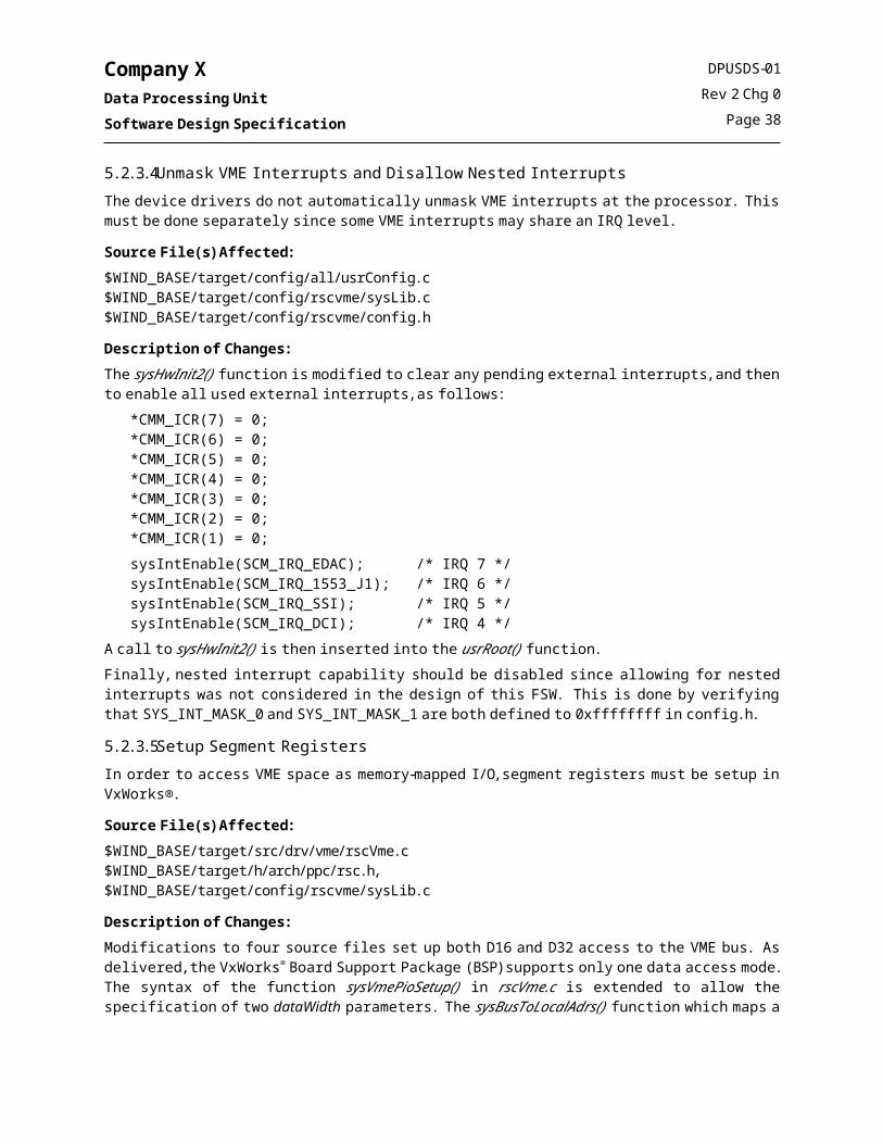
Company XData Processing UnitSoftware Design Specification
5.3.2.4 bitRead() - Restore previous BIT results from EEPROM into housekeeping structure.
SynopsisSTATUS bitRead
(UINT32 * pBitResults)
DescriptionReads the BIT results from the location pointed to by pBitResults (which is assumed to be in EEPROM) into the BIT results data structure in DRAM.
ReturnsOK if successful, ERROR otherwise.
5.4 Error Detection and Correction CSCThe Error Detection and Correction (EDAC) CSC is a Level 1 reuse component from the SSFF and INSTRUMENT Y projects. The EDAC CSC consists of a set of Interrupt Service Routines (ISRs) and a Memory Scrubber Task. The design of the INSTRUMENT Y EDAC CSC is described in document CIDPSDS-01.The only design change was to add logic to check for excessive external (SCM) EDAC interrupts. Refer to ECR 15-EDAC-94.
5.5 1553 Driver CSCThe MIL-STD-1553B (1553) Driver CSC is a Level 1 reuse component from the SSFF and INSTRUMENT Y projects. The 1553 Driver is compatible with the UTMC SMMIT™ controller on the SCM. The design of the 1553 Driver CSC is described in document CIDPSDS-01. No design changes are anticipated for this CSC.
5.6 Generic VME Driver CSCThe Generic VME (GVME) Driver CSC is a Level 1 reuse component from the INSTRUMENT Y project. The GVME Driver provides a set of convenience routines which are useful when accessing registers and memory in the VME memory space. The design of the 1553 Driver CSC is described in document CIDPSDS-01. No design changes are anticipated for this CSC.
DPUSDS-01Rev 2 Chg 0
Page 42

Company XData Processing UnitSoftware Design Specification
5.7 Analog to Digital Converter Driver CSCThe Analog to Digital Converter (ADC) Driver CSC is a new driver which controls and retrieves data from the ADC hardware. The key elements of the ADC driver include:
A list (array of ADC_LIST_ENTRY) which maintains the setup information and current value (ADC_VALUE) for each of the 24 ADC values. An API function, adcUpdateNext(), which causes a single ADC_VALUE to be updated every other call to the driver. A value is updated every other call since each value requires a multiplexer settle time as well as an ADC conversion time. In order to keep the driver simple, the responsibility for implementing the correct settle time and conversion time rests with the application. An API function, adcGet(), which returns a copy of the current list of ADC_VALUEs.
5.7.1 InitializationThe driver is initialized by invoking the initialization function adcInit(). The function initializes the ADC_LIST_ENTRY array, sets up convenience pointers to the ADC hardware registers, and sets up the ADC multiplexer for the first conversion (otherwise the very first ADC value requires three calls to adcUpdateNext()). The ADC Driver can be re-initialized, which will result in the values in the ADC_LIST_ENTRY array being reset to their default values.The ADC_VALUEs are A-bit data items; however the hardware contains a B-bit A/D. The upper bits are used to indicate invalid or suspect values as follows:
At initialization, the MSbit of each of the ADC_VALUEs is set (0x8000). If a conversion fails (i.e. the driver reads the analog value and determines that the conversion has not yet completed), the second MSbit.
5.7.2 Performing Analog-to-Digital ConversionsThe ADC Driver maintains an array of ADC_LIST_ENTRY data structures which contain the hardware multiplexer setup information for each of the x analog inputs, and the current value (ADC_VALUE) of each analog input. To update a single value in the list, an application must call the update function adcUpdateNext(). The ADC hardware only has a single A/D channel, and so to perform an A/D conversion the hardware requires a multiplexer setup and corresponding settle time, as well as the normal A/D conversion time. Therefore, it takes two calls to adcUpdateNext() to update a single value in the list. To keep the driver simple and to avoid embedding hard waits in the driver, the application is required to implement the setup and conversion time by spacing successive calls to the adcUpdateNext() function appropriately. Refer to document y, SCM Specification for the worst-case mux settle and conversion times.
5.7.3 Retrieving ADC Current ValuesAn application can retrieve the current list of ADC_VALUEs by calling the adcGet() function. This function copies the ADC_VALUEs into an array provided (via pointer) by the calling application. The list of ADC_VALUEs is provided in the following table.
Table 8. ADC Driver CSC – List of ADC Values
# Description # Description
0 +5 V Reference 12 Thermistor 05 (Not Connected)
1 -5 V Reference 13 Thermistor 06 (ICU CPU)
2 Analog Input from J1 Pin 3 External Connector 14 Thermistor 07 (ICU Interface)
3 -12 V (scaled by 0.417) 15 Thermistor 08 (Not Connected)
DPUSDS-01Rev 2 Chg 0
Page 43

Company XData Processing UnitSoftware Design Specification
Table 8. ADC Driver CSC – List of ADC Values
# Description # Description
4 +12 V (scaled by 0.417) 16 Thermistor 09 (Not Connected)
5 +5 V (DPU) 17 Thermistor 10 (Not Connected)
6 +5 V (ICU) 18 Thermistor 11 (Not Connected)
7 Ground 19 Thermistor 12 (Not Connected)
8 Thermistor 01 (Not Connected) 20 +55 deg C Reference
9 Thermistor 02 (Power Supply B) 21 +25 deg C Reference
10 Thermistor 03 (Power Supply A) 22 -5 deg C Reference
11 Thermistor 04 (SCM Summit Chip) 23 -35 deg C Reference
5.7.4 ADC Driver FunctionsThe ADC Driver CSC is a non-standard device driver (i.e is not integrated with the VxWorks™ standard I/O system). The driver functions are listed in alphabetical order.
5.7.4.1 adcGet() – Get the current list of ADC_VALUEs
SynopsisSTATUS adcGet
(ADC_VALUE *adcBuf,UINT16 *muxReg,UINT16 *dataReg)
DescriptionReturns a copy of the array containing the current values for each of the ADC_VALUEs.
ReturnsOK, or ERROR if the driver has not been installed.
5.7.4.2 adcInit() – Initialize the ADC Driver
SynopsisSTATUS adcInit
(UINT32 baseAdrs)
DescriptionThe function initializes the ADC_LIST_ENTRY array, sets up convenience pointers to the ADC hardware registers, and sets up the ADC multiplexer for the first conversion (otherwise the very first ADC value requires three calls to adcUpdateNext()). The ADC Driver can be re-initialized, which will result in the values in the ADC_LIST_ENTRY array being reset to their default values.
ReturnsOK, or ERROR if a base address was not provided.
DPUSDS-01Rev 2 Chg 0
Page 44

Company XData Processing UnitSoftware Design Specification
5.7.4.3 adcUpdateNext() – Update the next entry in the array of ADC_VALUEs
SynopsisSTATUS adcUpdateNext (void)
DescriptionUpdates the next entry in the array of ADC_VALUEs. The function must be called twice to update a single value. “Even” calls read the result of the prior conversion and setup the multiplexer for the next value. “Odd”calls start the conversion setup in the previous call.
ReturnsOK, or ERROR if the driver has not been installed or if the conversion has not completed.
5.7.5 ADC Driver Error NumbersThe ADC Driver CSC error numbers are listed in the following table. The driver communicates errors by setting the global variable errno.
Table 9. ADC Driver CSC Error Numbers
Error Number Description
S_adc_CONV_FAIL An ADC conversion failed to complete, or the application failed to wait a sufficient amount of time between calls.
S_adc_INIT_NOBASE A base address was not provided to the initialization function. Initialization failed.
S_adc_NOT_INSTALLED A driver API function was called before the driver was initialized.
DPUSDS-01Rev 2 Chg 0
Page 45

Company XData Processing UnitSoftware Design Specification
5.8 Synchronous Serial Interface Driver CSCThe Synchronous Serial Interface (SSI) Driver CSC is a new driver which provides an application layer interface to the SSI hardware. The SSI Driver CSC is implemented on top of the VxWorks™ tyLib library to manage its ring buffers. The driver features a standard I/O interface which utilizes an extended ioctl() command set to support unique SSI hardware attributes. This driver is patterned after the older VxWorks® 5.2 serial driver architecture rather than the newer Tornado serial driver architecture due to the lack of programmer control over I/O in the newer Tornado driver architecture.
5.8.1 Standard I/O InterfaceThe following figure illustrates the relationship between the VxWorks® I/O System, tyLib, and SSI Driver CSC.
Figure 13. SSI Driver CSC, Call Structure
The meaning of the standard primitives are described in the following sections.
DPUSDS-01Rev 2 Chg 0
Page 46
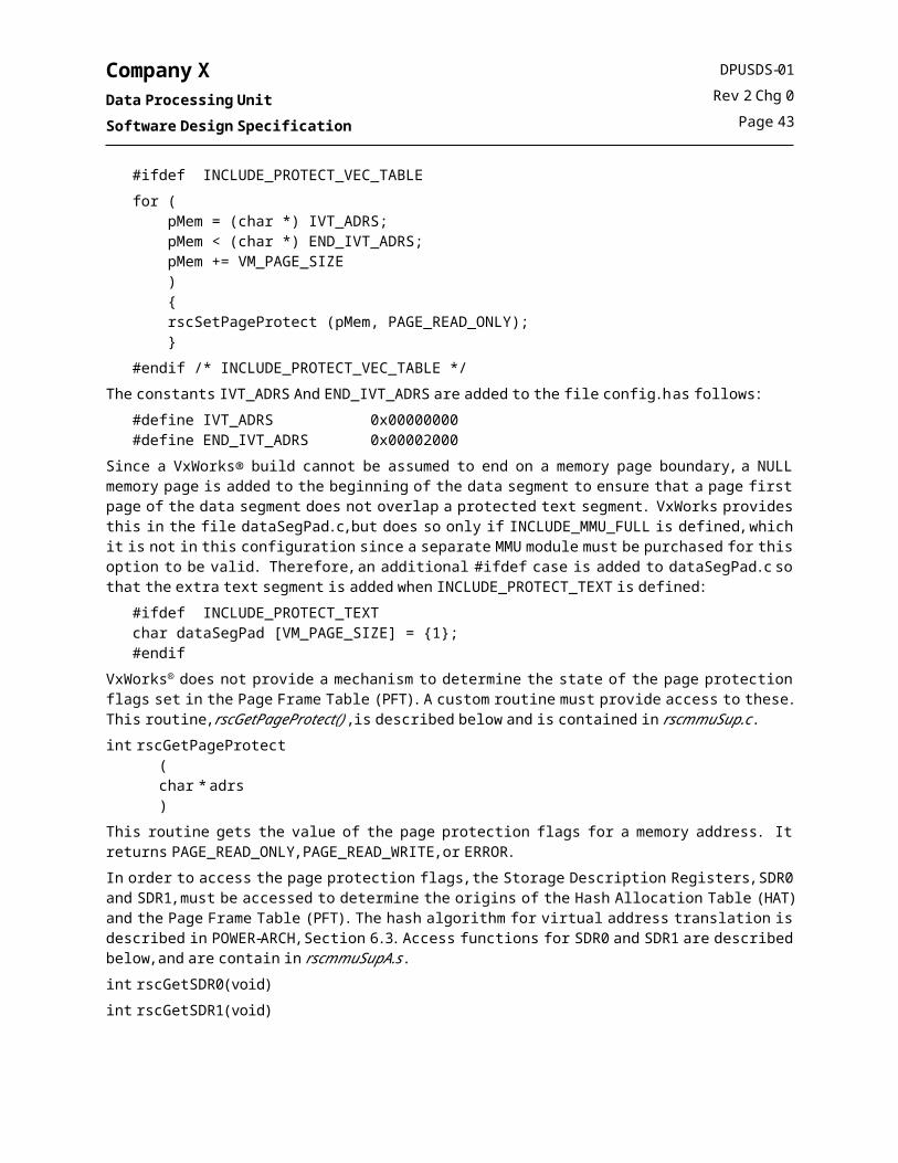
Company XData Processing UnitSoftware Design Specification
5.8.1.1 open(), creat()The open(), and creat() primitives return a unique file descriptor which is used to access the SSI port on the Company X Communications Module. Once the port has been opened by a running task, it cannot be opened by another running task. The driver will return an ERROR if an application tries to open a port that has already been opened.By default, open initializes the driver with no messaging mode set for either Rx or Tx. The internal semaphore used to block calling applications is initialized to WAIT_FOREVER, and all event counters are set to zero. The device name for accessing the SSI ports is shown in the following table.
Table 10. SSI Driver CSC Device Names
Device Name SSI Port
“/ssi1” Serial 1
The mode and flags parameters are ignored by the driver.
Error NumbersS_objLib_OBJ_UNAVAILABLE - A semaphore timeout occurred.
5.8.1.2 close()The close primitive releases access to the port.
5.8.1.3 read()The read() primitive does not block. The read() primitive is implemented by simply passing its parameters to the tyLib function tyRead().The size of the Rx ring buffer is specified in the call to ssiDevCreate() as part of the device instantiation.This routine returns either the number of bytes read, or ERROR.Error NumbersS_ssi_WRT_ODD_ERROR – write() was called with an odd maxBytes parameter. Only an even number of bytes may be written to the interface.
5.8.1.4 write()The write primitive does not block. The write() primitive is managed by the tyLib function, tyWrite() when the driver is not in BGTX Message Mode. The size of the Tx ring buffer is specified in the call to ssiDevCreate() as part of the device instantiation.This routine returns either the number of bytes written, or ERROR.
Error NumbersS_ssi_WRT_ODD_ERROR – write() was called with an odd maxBytes parameter. Only an even number of bytes may be written to the interface.The FIOBAUDRATE command is ignored.
DPUSDS-01Rev 2 Chg 0
Page 47

Company XData Processing UnitSoftware Design Specification
5.8.1.5 ioctl() CommandsThe following table lists and describes the SSI ioctl() commands.
Table 11. SSI Driver CSC ioctl() Commands
Command Arg parameter Description
FIOSSIBGREGGET N/A Get the Interblock gap register contents
FIOSSIBGREGSET UINT8 Set the Interblock gap in increments of 50 us.
FIOSSIBGRXHOOKADD VOIDFUNCPTR Installs callback to application level function on the Read Interblock gap interrupt.
FIOSSIBGTXHOOKADD VOIDFUNCPTR Installs callback to application level function on the BGTX interrupt.
FIOSSIBGTXMSGENABLE BOOL Enables Interblock Gap Transmit Message Mode. In transmit message mode, the BGTX interrupt is used to synchronize the sending of messages. The maxBytes parameter passed to write() is saved on a special queue, and only that many bytes are transmitted until the next Interblock Gap Transmit Interrupt. Driver Tx related queues are flushed when this routine is called. Byte Counters are reset to their initial state.
FIOSSIDRVSTATCLR N/A Clears internal Driver status information except for Read and Transmit Message modes and their related mode information.
FIOSSIDRVSTATGET SSI_STAT Returns information about SSI driver: Hook addresses, BG modes, # Recv Errs, #interrupts.
FIOSSIERRHOOKADD VOIDFUNCPTR Installs a hook to respond to an error interrupt.
FIOSSIIEMASKSET UINT16 Sets Interrupt enable bits in the control register to the passed bit pattern. Protects all other bits in the control register.
FIOSSIINTENABLE BOOL SSI h/w interrupt enabled or disabled depending on argument. TRUE=enable, FALSE=disable.
FIOSSISTATREGGET UIN16 * Returns the current SSI Status register contents.
FIOSSIRXENABLE BOOL Enable/Disable the ability for the SSI to receive data.
FIOSSIRXRESET N/A Flushes the hardware receiver FIFO.
FIOSSISSIRESET N/A Resets SSI hardware to POWER on state.
FIOSSITXNOW N/A Transmit data waiting in hardware transmitter FIFO.
FIOSSITXRESET N/A Flushes the hardware transmitter FIFO.
Any other value of the command parameter is passed to the tyIoctl() function of tyLib. The following calls supported by tyLib apply to this device:
FIOFLUSH FIOGETNAME FIOISATTY FIORBUFSET FIORFLUSH FIOWBUFSET FIOWFLUSH
All other default tyLib ioctl functions are not supported by this driver. They will be intercepted by ssiIoctl and ERROR will be returned.
DPUSDS-01Rev 2 Chg 0
Page 48

Company XData Processing UnitSoftware Design Specification
5.8.2 Transmit Message Mode (FIOSSIBGTXMSGENABLE) and Inter-Block Gap interruptsThe SSI Driver CSC supports a message mode to facilitate application level communication. This mode uses the Inter-Block Gap interrupt generated by the hardware to synchronize message transmission. When in a messaging mode, the driver enables an internal Byte Count queue provides a synchronization mechanism for sending messages. This Byte Count queue is updated with the message size as Inter-Block Gap interrupts are received. The Transmit Message Mode uses the BGTX interrupt, the Tx FIFO Empty Interrupt, the write() call, and an internal Byte Count queue to synchronize the transmission of messages over SSI. In this mode, the maxBytes parameter passed to write() is enqueued to the Byte Count queue. When a period of time equal to or greater than the Interblock Gap time has expired, the BGTX interrupt will be asserted. At this time, the driver will respond and initiate a new transfer by setting a Byte Transfer Limit for this block and enabling the Tx FIFO Empty Interrupt. The Byte Transfer Limit corresponds to the entry on the Byte Count queue. When all bytes in the current block have been sent up to the Byte Transfer Limit, the Tx FIFO ISR will disable itself and reset the Byte Transfer Limit to zero.An application may use this mode by calling write() with a buffer pointer and maxBytes in order to transfer a message of a particular length.
5.8.3 Hardware InterfacesThe SSI Driver CSC accesses each of the registers on the Company X Communications module using D16 VME access.
5.8.4 InitializationThe SSI Driver CSC is initialized by calling the function ssiDrv() from the startup task usrRoot().
Table 12. SSI Driver CSC Global Data
Global Name Data Type Description Scope Create Read Write
SsiWritingFifo BOOL Flag variable used to prevent race conditions between a calling task and an interrupt when writing data to the transmit FIFO.
Local X X X
SsiRxByteCount UINT32 Used to count incoming bytes on a interblock gap delimited command.
Local X X X
5.8.5 SSI Error NumbersThe SSI Driver CSC error numbers are listed in the following table.
Table 13. SSI Driver CSC Error Numbers
Error Number Description
S_ssi_DRIVER_INSTALLED Driver already Installed
S_ssi_DRV_INSTALL_ERROR Failed internal call to iosDrvInstall
S_ssi_FUNC_NOTSUPPORTED Ioctl function not supported
S_ssi_INT_CONNECT_ERROR Failed internal call to intConnect
S_ssi_IOS_DEV_ADD_ERROR Failed internal call to iosDevAdd
S_ssi_MALLOC_ERROR Cannot Allocate Memory
S_ssi_MODE_ERROR Operation requested is invalid under the current driver mode
DPUSDS-01Rev 2 Chg 0
Page 49

Company XData Processing UnitSoftware Design Specification
Table 13. SSI Driver CSC Error Numbers
Error Number Description
S_ssi_NULLPTR Null pointer passed as arg to ioctl call.
S_ssi_ORUN_BGTX_BCOUNT_Q Overrun of Internal Transmit Byte Count Queue
S_ssi_ORUN_BGTX_DATA_Q Overrun of Data Transmit Queue
S_ssi_SEM_CREATE_ERROR Failed to create needed Semaphore
S_ssi_SEM_TIMEOUT Semaphore has timed out
S_ssi_TYDEV_INIT_ERROR Failed internal call to TyDevInit
S_ssi_WRT_ODD_ERROR An attempt was made to write an odd number of bytes to the device.
DPUSDS-01Rev 2 Chg 0
Page 50

Company XData Processing UnitSoftware Design Specification
5.9 Data Capture Interface Driver CSCThe Data Capture Interface (DCI) Driver CSC is a new driver which provides a standard VxWorks™ driver interface to the DCI hardware. The driver features two modes: a test mode and a normal mode.
5.9.1 Standard I/O InterfaceThe following figure illustrates the relationship between the VxWorks® I/O System and DCI Driver CSC.
Figure 14. DCI Driver CSC, Call Structure
The meaning of the standard primitives are described in the following sections.
5.9.1.1 open(), creat()
The open(), and creat() primitives returns a unique file descriptor which is used to access a single DCI port on the Company X Communications Module. Once the port has been opened by a running task, it cannot be opened by another running task. The driver will return an ERROR if an application tries to open a port that has already been opened.By default, open() initializes the driver in NORMAL mode. An ioctl call may be issued to force into TEST mode.The device name for accessing the DCI ports is shown in the following table.
Table 14. DCI Driver CSC Device Names
Device Name Hardware Mapping“/dci1” SCM DCI H/W interface
The mode and flags parameters are ignored by the driver’s open() call. The driver’s mode is toggled between normal and test through ioctl.
5.9.1.2 close()The close primitive releases access to the port.
DPUSDS-01Rev 2 Chg 0
Page 51

Company XData Processing UnitSoftware Design Specification
5.9.1.3 read()The read() primitive does not block. A read is performed on the active portion of the H/W ping pong buffer using the RAD 6000 move-multiple instruction, referred to here after as a “block move”. For optimum performance, the block move is implemented in assembler. The number of bytes read is returned to the caller. See table 5.9.4 for a description of error codes associated with this routine.
5.9.1.4 write()The write primitive does not block. The buffer passed to write is written directly to the active portion of the ping pong buffer by the driver. This primitive is valid only in TEST mode. The write call will set errno to S_dci_MODE_ERROR and return ERROR if the driver is in NORMAL mode. In TEST mode, the driver returns the number of bytes written. See table 5.9.4 for a description of additional error codes associated with this routine.
5.9.1.5 ioctl()The ioctl() entry point controls all interface configuration. Different commands may be available depending on whether the driver is in NORMAL or TEST mode. The following table lists and describes the DCI ioctl() commands.
Table 15. DCI Driver CSC ioctl() Commands
Command Arg parameter Return Value Valid Mode Description
FIOACQENABLE BOOL Int BOTH Sets the hardware acquisition bit
FIOAPINGRGET N/A UINT32 BOTH Gets the current word address of the last write location in Ping Memory
FIOAPONGRGET N/A UINT32 BOTH Gets the current word address of the last write location in Pong Memory.
FIOBITARR BOOL Int BOTHForces DCI to arrange event data bits according to the pre-defined scheme as outlined in document 1400 section 4.3.2.4.1.1.
FIOERRHOOKADD VOIDFUNCPTR Int BOTHInstalls callback for the Error Interrupt; Hook is passed the UINT16 value from the status register as its only argument.
FIOFRMHOOKADD VOIDFUNCPTR Int BOTHInstalls callback for Frame Limit Interrupt; Hook is passed the UINT16 value from the status register as its only argument.
FIOIEMASKSET UINT16 Int BOTH Sets Interrupt enable bits in the control register to the passed bit pattern.
FIOINTENABLE BOOL Int BOTH Enables the VME Slave interruptor.
FIOISMASKSET UINT16 Int BOTH Sets Interrupt status bits in the control register to the passed bit pattern.
FIOMODEGET N/A Int BOTH Returns mode. Possible values = DCI_MODE_TEST or DCI_MODE_NORMAL.
FIOMODESET Int Int BOTH Sets mode to either DCI_MODE_TEST or DCI_MODE_NORMAL.
FIONREAD N/A Int BOTH
Returns the number of bytes waiting to be read from the current read location. Automatically determines whether PING or PONG is selected for reading, and returns the number of bytes waiting to be read from the selected read buffer.
FIOPPARM N/A Int BOTH Arms hardware to swap Ping Pong buffer when Ready.
DPUSDS-01Rev 2 Chg 0
Page 52

Company XData Processing UnitSoftware Design Specification
Table 15. DCI Driver CSC ioctl() Commands
Command Arg parameter Return Value Valid Mode Description
FIOPPCLR N/A Int TEST
Clears all data from currently selected Ping Pong buffer. Either = DCI_PONG or DCI_PING. Resets the APONG or APING to zero by forcing a swap. Therefore, if PING is active when executed, this command will reset APONG and visa versa.
FIOPPDEPTHGET N/A UINT16 BOTHNumber of frames, max 64, to be read into currently selected Ping Pong buffer before interrupting.
FIOPPDEPTHSET UINT16 Int BOTHNumber of frames, max 64, to be read into currently selected Ping Pong buffer before interrupting.
FIOPPSEL Int Int TEST Select either DCI_PING or DCI_PONG.
FIOREADRESET N/A Int BOTH Resets the read offset to 0. The driver maintains a read offset within the buffer.
FIOREGSTATGET Void UINT16 BOTH Returns the bit pattern currently residing in the DCI H/W status register.
FIORESET Void Int BOTH Resets the DCI hardware to the power on state.
FIOTOHOOKADD VOIDFUNCPTR Int BOTHInstalls callback for the Timeout Interrupt; Hook is passed the UINT16 value from the status register as its only argument.
FIOTORGET N/A UINT16 BOTH Returns the value of the Time Out register.
FIOTORSET UINT16 Int BOTH
Writes the passed value to the Time Out register. The value represents the number of DCI clock ticks (1 ms each) to wait after the last word is received before interrupting.
FIOWINENABLE BOOL Int BOTHEnables hardware filtering on the event stream according to the clipping region parameters passed through FIOXYWINSET.
FIOXYWINGET XY_HW_WIN * Int BOTH Gets the filter description for the event clipping region.
FIOXYWINSET XY_HW_WIN * Int BOTH Sets the filter description for the event clipping region.
Any other value of the command parameter causes errno to be set to S_dci_IOCTL_UNDEF and ERROR to be returned.
5.9.2 Hardware InterfacesThe DCI Driver CSC accesses each of the registers on the Company X Communications module using D16 VME access mode. Reads from DCI memory are performed in VME D32 mode via a special assembly language routine which uses the lwm/stm instructions to minimize the transfer time.
5.9.3 InitializationThe DCI Driver CSC is initialized by calling the functions dciDrv() and dciDevCreate() from the startup task usrRoot().
DPUSDS-01Rev 2 Chg 0
Page 53

Company XData Processing UnitSoftware Design Specification
5.9.4 DCI Error NumbersThe error numbers produced by the DCI Driver CSC are listed in the following table.
Table 16. DCI Driver CSC Error Numbers
Error Number Description
S_dci_ALIGN_ERROR Read or Write passed unaligned memory address. Returned by read() and write().
S_dci_CLOSE_ERROR Failed to properly close the device. Returned by close().
S_dci_DRIVER_INSTALLED Driver already Installed. Returned by dciDrv().
S_dci_DRV_INSTALL_ERROR Failed internal call to iosDrvInstall(). Returned by dciDevCreate().
S_dci_INSTANCE_OPEN This device instance is already open. Returned by open().
S_dci_INT_CONNECT_ERROR Failed internal call to intConnect. Returned by dciDevCreate().
S_dci_IOCTL_UNDEF Ioctl function not understood. Returned by ioctl().
S_dci_IOS_DEV_ADD_ERROR Failed internal call to iosDevAdd(). Returned by dciDevCreate().
S_dci_LIMIT_VIOLATION Read or Write attempted past physical memory limits. Returned by read() and write().
S_dci_MALLOC_ERROR Cannot Allocate Memory. Returned by dciDevCreate().
S_dci_MODE_DENY Operation requested is invalid under the current driver mode. Returned by write() and ioctl().
S_dci_MODE_ERROR Mode requested is not valid. Returned by ioctl().
S_dci_NULLPTR Null pointer was passed in as arg. Returned by ioctl().
S_dci_PP_INVALID An invalid PP buffer was requested. Returned by ioctl().
S_dci_SEM_CREATE_ERROR Failed to create needed Semaphore. Returned by dciDevCreate().
S_dci_SEM_TIMEOUT Semaphore has timed out
DPUSDS-01Rev 2 Chg 0
Page 54

Company XData Processing UnitSoftware Design Specification
5.10 EEPROM Driver CSCThe EEPROM Driver (EEPRM) CSC is a Level 1 reuse component from the SSFF and INSTRUMENT Y projects. The EEPROM Driver CSC provides an API to the EEPROM on the SCM. The design of the INSTRUMENT Y EEPROM Driver is described in document CIDPSDS-01. The EEPROM Driver for the Company X DPU will be nearly identical to that used on the INSTRUMENT Y CIDP and SCU, with the exception of changes driven by hardware differences. The design changes impact only constant #defines within the included header files. These changes are listed below:
Table 17. EEPRM Driver CSC Constants
Symbolic Name (#define) File Original Value New Value
EEPROM_UB eeprm.h 0x800000 0x700000
SYSTEM_BLOCK_1 eeprm.h 63 0x2F
SYSTEM_BLOCK_2 eeprm.h 63 0x2F
DPU_CNFG_START_ADDR eeprm.h N/A (new constant) 0x0058
WARM_SKIP_BIT eeprm.h 0x0038 COLD_SKIP_BIT
WARM_MEM_SIZE eeprm.h 0x040C COLD_MEM_SIZE
CVT_START_ADDR eeprm.h 0x040C Deleted
5.11 EEPROM File System CSCThe EEPROM File System (EEFS) CSC is a Level 1 reuse component from the INSTRUMENT Y project. The EEFS CSC provides an MS-DOS compatible file system on the SCM EEPROM. The File System is created by using the dosFs File System included in VxWorks® with a standard VxWorks® block driver. The design of the INSTRUMENT Y EEFS CSC is described in document CIDPSDS-01. No design changes are anticipated for this CSC.
DPUSDS-01Rev 2 Chg 0
Page 55

Company XData Processing UnitSoftware Design Specification
5.12 Command and Control CSCThe Command and Control (CCM) CSC is a Level 2 reuse component from the INSTRUMENT Y project. The Command and Control CSC includes the following components:
A Control Task, ccmCtrlTask(), which initializes the DPU FSW and spawns other tasks at bootup, schedules the production of DPU housekeeping data packets, monitors the execution of other tasks, and schedules the execution of other periodic tasks such as the heartbeat message and the watchdog strobe; and A Command Dispatch Task, ccmCmdTask(), which receives and dispatches real-time commands received from the SCU or the ICU.
Major data structures include: A Static Data table that keeps track of the operational state. Data included in this table includes housekeeping production rates, CCM specific flags, and the number of commands executed. A Command Queue into which commands are placed when they arrive, via interrupt, from the ICU or the SCU. An Error/Event Queue which accumulates error and event codes which are reported by the DPU FSW. These error and event codes are removed from the queue and placed into a telemetry packet at a given interval and included in DPU housekeeping data.
5.12.1 Structural DesignThis section contains the detailed structural diagrams which describe the design of this CSC.
5.12.1.1 Flight Software InitializationThe Command and Control CSC is initialized by spawning the CCM Control Task, ccmCtrlTask(), from the operating system startup task, usrRoot(). After the task is spawned it calls a function, ccmInit(), which creates the error/event queue, instantiates needed semaphores and installs various ISRs. Finally, it spawns the remaining tasks which comprise the DPU FSW.
DPUSDS-01Rev 2 Chg 0
Page 56
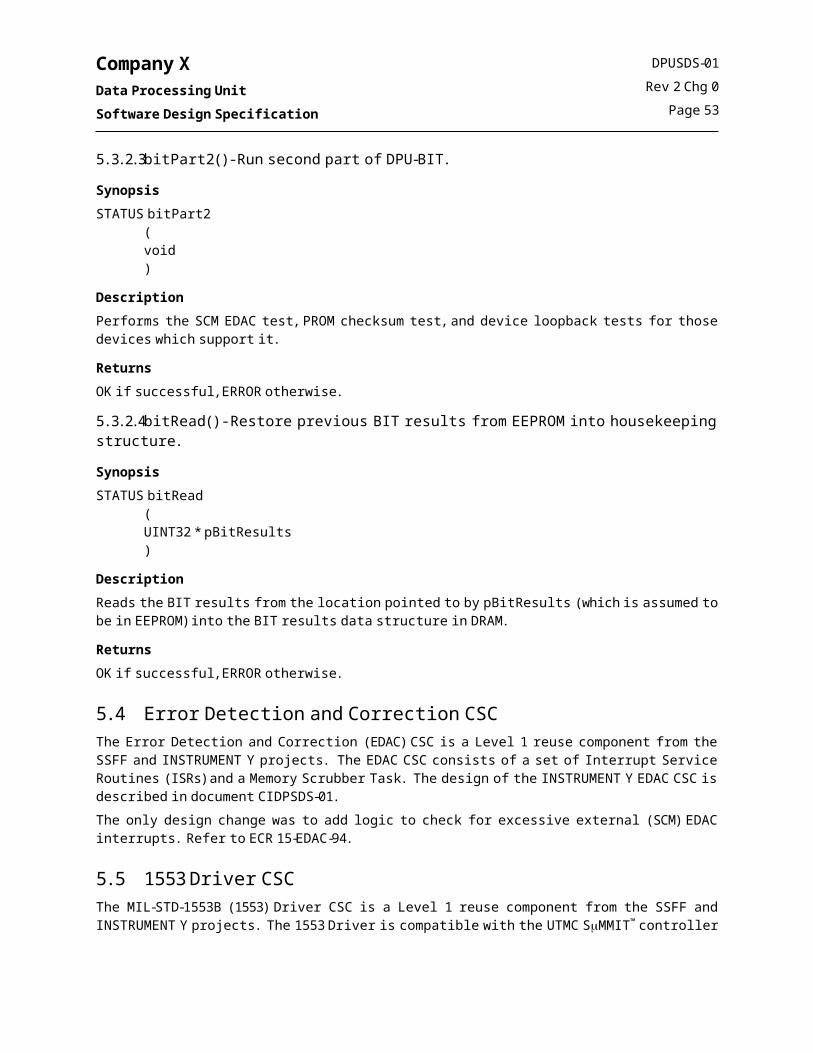
Company XData Processing UnitSoftware Design Specification
A structure chart illustrating the initialization function, ccmInit(), is shown in the following figure.
ccmInit
tisInit
ccmErrorQueueCreate
STATUS
STATUS
UINT32 cpuSpeed
semBCreate
SEM_IDccmSemWakeUp
ccmHkInit
ccmTaskSpawn
STATUS
BOOL primary1PPSBOOL autoSync
ccmGetBootDefaults
DPU_CNFG_PARMS *
DPU_CNFG_PARMS *
ccmSysBlkVerify
STATUS
eeprmRead
DPU_CNFG_PARMS *
sysSetBoardSpeed
icuiInit
ccmCmdLengthInit
Figure 15. CCM CSC, Structure Chart, ccmInit()
When the CCM Control Task starts up, it reads DPU configuration startup defaults from the SYSTEM_CONFIG_AREA in EEPROM. If the SYSTEM_CONFIG_AREA checksum is bad, hard-coded defaults are used as described in the following table. The CCM Control Task initializes the remaining CSCs by calling the applicable initialization function, or if the CSC has an associated task, by spawning the task using the VxWorks® function, taskSpawn(). When the CCM Control Task initializes a CSC, it passes the startup defaults read from EEPROM as parameters to the task initialization function.
Table 18. Hard-Coded DPU Bootup Defaults
Startup Parameter Default Value Startup Parameter Default Value
DPU_CTRL_STATUS 0x118 EDAC_MODULUS 0x2000 (double words)
SCU_POLL_RATE 9 (Hz) EDAC_DELAY 6 (ticks)
SCU_BUFFER_RATE 7664 (Bits/poll) DPA_PARM1 0
SCU_LOW_BUFFER_SIZE 23068672 (22 MB) DPA_PARM2 0
SCU_HIGH_BUFFER_SIZE 10240 (10 KB) DPA_PARM3 0
TMALI_PP_LIMIT 10 DPA_PARM4 0
TMALI_TIMEOUT 125 msec DPA_PARM5 0
TMALI_BUFFER_SIZE 15728640 (15 MB) DPA_PARM6 0
DCX_BUFFER_SIZE 46137344 (44 MB) CPU_SPEED 4
DPUSDS-01Rev 2 Chg 0
Page 57

Company XData Processing UnitSoftware Design Specification
In addition to its task initialization activities, ccmInit(), also initializes the command length verification table by calling ccmCmdLengthInit(). The command processor uses the created table to verify expected command lengths for newly received commands.
5.12.1.2 Control and MonitoringAs described above, the CCM Control Task initializes the DPU FSW. It is the responsibility of the CCM Control Task to establish a successful boot. It does so by blocking on temporary semaphores, each with a 5 second timeout, after spawning the SCU Interface Task and the CCM Command Task. If both of these tasks report a successful initialization by giving the semaphore, the CCM Control Task toggles the BC_INDEX parameter in EEPROM to indicate a successful boot. If either task does not report a successful initialization, the CCM Control Task disables the watchdog strobe to effect a reboot of the DPU. The rationale for selecting the successful initialization of these two tasks as the definition of a successful boot is that the DPU FSW requires these tasks, as a minimum, to establish ground contact and provide commandability.Once this initialization is complete, the task blocks on a binary semaphore which is given by the SCUI Command ISR upon arrival of the 1 Hz Clock Message. In the event a Clock Message does not arrive, the semaphore will time out after 1.5 seconds. The CCM Control Task remains alive to create and transmit DPU housekeeping at the appropriate intervals, perform various periodic processing tasks, and to process memory dump commands. Each of these activities will be described and illustrated in more detail in the following sections.A structure chart illustrating the CCM Control Task function, ccmCtrlTask(), is shown in the following figure. Software modules for each of the major activities performed by the ccmCtrlTask() are shown. The final call to ccmErrEnq() is performed in order that if an error occurs in an interrupt service routine, a global variable is set to the value of the errno which is then enqueued into the Error/Event Queue as part of this task’s normal processing.
Figure 16. CCM CSC, Structure Chart, ccmCtrlTask()
DPUSDS-01Rev 2 Chg 0
Page 58

Company XData Processing UnitSoftware Design Specification
5.12.1.2.1 HousekeepingThe DPU produces eight types of housekeeping packets which are listed in the following table. The structure and content of each of the housekeeping packets is shown in the tables in Appendix A.
Table 19. DPU Housekeeping Packets
Packet Name Packet APID Frequency Packet Description
Startup Config Packet 0x240(Realtime)
0x2A0(Stored)
Once at bootup
Contains startup configuration data. Generated and transmitted following DPU bootup only. The DPU can be commanded to resend the startup packet.
The original copy of this packet goes down the realtime link only at system boot. Resent packets may commanded to go down either the realtime or TDRSS link.
Startup BEV Packet 0x242(Realtime)
0x2A2(TDRSS)
Once at bootup
Contains built-in-test results and the last recorded exception vector (BEV). Generated and transmitted following DPU bootup only. The DPU can be commanded to resend the startup packet (both the Startup Config and Startup BEV Packets are resent).
The original copy of this packet goes down the realtime link only at system boot. Resent packets may commanded to go down either the realtime or TDRSS link.
High Rate Packet 0x244(Realtime)
0x2A4(TDRSS)
Z secs Contains regular housekeeping values which change regularly.
The DPU can be commanded to copy housekeeping information to TDRSS.
Low Rate Packet 0x248
(Realtime)
0x2A8(TDRSS)
S mins Contains regular housekeeping values which change at a low rate or which are not expected to change at all.
The DPU can be commanded to copy housekeeping information to TDRSS.
Error/Event Packet 0x24E(Realtime)
0x2AE(TDRSS)
Error/event Contains up to 50 error/event codes. Generated only when an error or event is reported by the DPU FSW. The DPU will queue up error/event codes and report up to 50 of them every 10 seconds if any are present on the error/event queue.
The DPU can be commanded to copy housekeeping information to TDRSS.
Command Echo Packet 0x24C(Realtime)
0x2AC(TDRSS)
Command execution
Contains a single command packet. Generated only when enabled and when a command has been received by the DPU FSW.
The DPU can be commanded to copy housekeeping information to TDRSS.
Memory Dump Packet 0x25D(Realtime)
0x2BD(TDRSS)
0x35D(Stored)
Response to memory dump
command
Contains the contents of a commanded section of memory. Generated in response to a memory dump command.
The DPU can be commanded to dump memory to a realtime packet, TDRSS, or a stored packet.
Block Dump Packet 0x25B(Realtime)
0x2BB(TDRSS)
0x35B(Stored)
Response to EEPROM filesystem
block dump command
Generated in response to a command to dump a block from the EEPROM Filesystem.
The DPU can be commanded to dump memory to a realtime packet, TDRSS, or a stored packet.
DPUSDS-01Rev 2 Chg 0
Page 59

Company XData Processing UnitSoftware Design Specification
5.12.1.2.2 DPU Monitoring and Periodic ProcessingEvery time the CCM Control executes, it calls ccmPerProcess() to handle periodic processing responsibilities. Such responsibilities include analog to digital conversion updates, DPU task monitoring, ICU heartbeat message production, and watchdog strobe. A structure chart for the ccmPerProcess() function is shown in the following figure.
ccmPerProcess
icuiHBSend ccmWdStrobeccmHealthChk
STATUS
ICUI_HBEAT_MSG
ccmRebootadcUpdateNext()
Figure 17. CCM CSC, Structure Chart, ccmPerProcess()
The ccmHealthChk() function, called by ccmPerProcess() verifies the execution of other tasks by monitoring the amount of time that has elapsed since each task last reported. Other tasks report their execution to the CCM Control Task by calling the function, ccmTaskReport(), providing their task index. Each task has an expected execution frequency, and if a task does not execute as expected, an error is reported in DPU housekeeping. If the Command Dispatch Task fails to report for an extended period, the DPU will execute a reboot, since it is impossible to command the DPU if this task is not executing, otherwise it will strobe the watchdog.
5.12.1.2.3 Memory Dump HandlingIn addition to its other activities, the CCM Control Task also handles memory dump commands. In the event of a data dump command, the CCM Control Task will break the dump into manageable pieces and dump a small portion at a time, each time the task is awakened. The purpose of this “deferred” activity is to prevent a large dump from consuming available CPU time by keeping the high-priority CCM Command Dispatch Task busy for an extended period. A structure chart for the deferred processing handler, ccmDefProcess(), is shown in the following figure.
DPUSDS-01Rev 2 Chg 0
Page 60

Company XData Processing UnitSoftware Design Specification
Figure 18. CCM CSC, Structure Chart, ccmDefProcess()
The format of the dump packets is provided with the Housekeeping Packet definitions in Appendix A.
5.12.1.3 Command HandlingThe following table summarizes the commands which the DPU will accept. The DPU accepts commands via two interfaces – from the Spacecraft via the MIL-STD-1553 interface, and from the ICU via the SSI interface. Any of the DPU commands can be sent from the SCU or the ICU. The source for a command from the DPU is one of the following:
ICU – command is generated and sent by the ICU via the SSI. SCU – command is generated and sent by the SCU via the 1553. G-ICU – command is generated on the ground and sent to the DPU via the ICU/SSI. G-SCU – command is generated on the ground and sent to the DPU via the SCU/1553.
The table indicates the nominal source for each command.Detailed formats for each command are provided in Appendix B.
Table 20. DPU Commands
Command MnemonicNominal Source Description Code
D_DCX_Q_PURGE ICU Purges the data compression queue – see DPUICD-01. 0x40
D_DPA_DCX_ENABLE G-ICU Enable/disable data compression 0x10
D_DPA_MODE ICU Sets the current science mode – see DPUICD-01. 0x05
D_DPA_MODE_ABORT ICU Stop the current science mode – see DPUICD-01. 0x0A
D_DPA_MODE_STOP ICU Stop the current science mode – see DPUICD-01. 0x06
DPUSDS-01Rev 2 Chg 0
Page 61

Company XData Processing UnitSoftware Design Specification
Table 20. DPU Commands
Command MnemonicNominal Source Description Code
D_DPA_RES_CMDS G-ICU As of yet unrealized DPA commands. CCM acts as a bent-pipe command forwarding entity.
0xC0 – 0xDF
D_DPA_XRT_POS ICU Update the current XRT Position and window – see DPUICD-01.
0x09
D_HK_CECHO_ENABLE G-ICU Enable/disable command echo. 0x11
D_HK_P_CPY_TDRSS SCU Copy the HK packets down TDRSS 0x37
D_HK_RATES_SET G-ICU Set rate at which high rate housekeeping packet is generated.
0x12
D_HK_START_SEND G-ICU Resend the startup housekeeping packet 0x14
D_MEM_BLK_DNLD G-SCU Download data from DPU EEFS 0x1A
D_MEM_CHKS_32 G-SCU Compute a 32-bit additive checksum over given DPU memory range
0x15
D_MEM_DAT_CNCL G-SCU Cancel an upload 0x19
D_MEM_DAT_DNLD G-SCU Download data from DPU memory 0x16
D_MEM_DAT_POKE G-SCU Poke up to X bytes (TBbR) into DPU memory 0x17
D_MEM_DAT_UPLD G-SCU Upload data to DPU memory 0x18
D_MEM_BLK_DNLD G-SCU Download EEFS Block 0x1A
D_MEM_DISK_INIT G-SCU Initialize EEFS Disk 0x43
D_SCUI_ACS_MSG SCU Standard ACS message. 0x01
D_SCUI_CLK_MSG SCU Standard Clock message. 0x02
D_SCUI_Q_PURGE ICU Purges the low priority output telemetry queue – see DPUICD-01.
0x41
D_SCUI_RATES_SET G-ICU Set rate at which the Spacecraft polls the DPU for telemetry. 0x21
D_SYS_NOOP SCU Test NULL command 0x24
D_SYS_REBOOT ICU/G-ICU Reboot the DPU 0x42
D_SYS_SHELL G-ICU Execute a shell command 0x28
D_SYS_EXC_CLEAR G-ICU Clear EEPROM Exception information 0x44
D_SYS_TASK_PTY G-ICU Alter a task’s priority 0x25
D_SYS_TASK_RESM G-ICU Resume a suspended task 0x26
D_SYS_TASK_SUSP G-ICU Suspend a task 0x27
D_TIS_1PPS_SELECT G-ICU Select primary/alternate a PPS signal 0x30
D_TIS_SYNC_ENABLE SCU Enable/disable automatic clock synchronization with Spacecraft
0x31
D_TIS_TIME_SET SCU Manually jam given time into DPU clock 0x32
D_TMALI_DEPTH_SET G-ICU Set the ping/pong frame depth in the DCI hardware 0x33
D_TMALI_TO_SET G-ICU Set the data timeout in the DCI hardware 0x34
DPUSDS-01Rev 2 Chg 0
Page 62

Company XData Processing UnitSoftware Design Specification
When a command arrives from the SCU (via the 1553 interface) or the ICU (via the SSI interface), the respective ISR will enqueue the command packet into a Command Queue, and then give the semaphore to awaken the ccmCmdTask(). Since it is possible for the DPU to send a command to itself, commands may arrive at interrupt context or task context. Therefore the CCM maintains two queues – one for interrupt context which is not semaphore protected, and one for task context which is semaphore protected. A structure chart for ccmCmdEnq() is shown in the following figure.
Figure 19. CCM CSC, Structure Chart, ccmCmdEnq()
Commands are dequeued from the Command Queue and executed by the Command Dispatch Task, ccmCmdTask(). This task blocks on a semaphore which is given by ccmCmdEnq(). The ccmCmdTask() wakes on the semaphore and calls ccmCmdProcess() to process waiting commands. The ccmCmdProcess() function subsequently retrieves waiting commands from the Command Queue and invokes ccmCmdDispatch() to verify the expected length of the command and execute it. If command echo is enabled, ccmCmdDispatch() will call ccmHkMkCmdEcho() to blindly echo the command back to the ground. Counts for both rejected and executed commands are maintained. If the command sent to ccmCmdEnq() is either a 1 Hz Clock Time message or an Attitude message from the spacecraft, the command will not be forwarded to the Command Queue, but instead will be executed directly while still in interrupt context. Attitude messages are forwarded to dpaCommandSend(), while the 1 Hz Clock Time message’s parameters are passed to tisTimeSync() in order to synchronize the current time. Any other non DPU or spacecraft observatory messages are quietly discarded without reporting an error.In order to guarantee that ccmCmdTask() task reports in with the CCM Control Task periodically in absence of a ground command, the semaphore has a timeout value of 20 seconds. If the semaphore times out, the task will verify no commands are on the Command Queue, and then report in to the CCM Control Task by calling ccmTaskReport().
DPUSDS-01Rev 2 Chg 0
Page 63
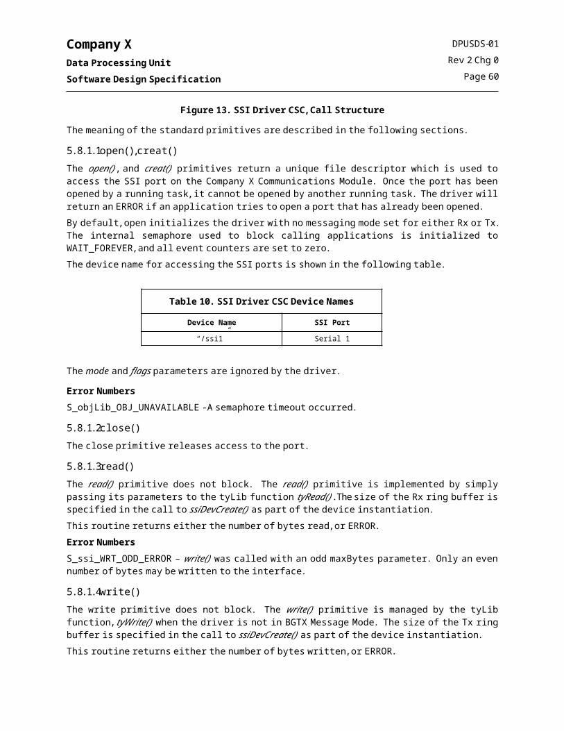
Company XData Processing UnitSoftware Design Specification
A structure chart for the ccmCmdTask() shown in the following figure.
ccmCmdTask
semTake ccmCmdProcess
SEM_IDccmCmdTaskSem STATUS
ccmTaskReport
TASK_ID
rngBufGet ccmCmdDispatch
RING_IDccmTaskCmdQ
or ccmISRCmdQCCM_CMD_HDR
DPU_CMD
rngBufGet
RING_IDccmTaskCmdQ
or ccmISRCmdQ
UINT16ccmCmdData[]
scuiEnq
DPU_CMD
ccmCmdInit
ccmCmdLenVerify
DPU_CMD STATUS STATUS
Figure 20. CCM CSC, Structure Chart, ccmCmdTask()
5.12.1.4 Memory Upload and Download HandlingThere are two ways to upload data to the DPU:
Memory Poke (D_MEM_DAT_POKE command), or Memory Upload (D_MEM_DAT_UPLD command).
The memory poke command is used when a small (<=Z bytes) of data need to be poked into a DPU memory location. The Z byte limitation is derived from the Company X command length constraint.When larger amounts of memory must be uploaded to the DPU, such as in the case of a software patch or full software upload, the regular memory upload is used. Memory uploads are accomplished by sending a series of individual D_MEM_DAT_UPLD commands, resulting in a single “virtual” upload. CCSDS-like sequence (grouping) flags are employed to allow the DPU FSW to accept up to a maximum of 65535 bytes in a single “virtual” upload. The data contained in each D_MEM_DAT_UPLD command is stored in a temporary DRAM buffer until all of the sequence numbers in the entire upload have been successfully received. When the DPU FSW receives the last command in the series, the FSW will verify that all sequence numbers have been received,
DPUSDS-01Rev 2 Chg 0
Page 64

Company XData Processing UnitSoftware Design Specification
verify the end-end upload checksum, and then write the entire temporary buffer to the target location specified in the first upload command.If more than 65535 bytes need to be uploaded, the upload file must be broken up into multiple smaller files, each less than or equal to 65535 bytes, and then each of the virtual uploads should be sent in series. Because of the sequence numbers, the DPU FSW can receive individual upload commands out of sequence. There is no time limit for the accomplishment of a single virtual upload, and so a long upload can continue across ground contacts. If an upload is in progress, the last sequence number can be sent to the DPU FSW and it will report the list of missing sequence numbers via event number S_ccm_MISSING_SEQNO. If an upload is in progress and needs to be cancelled, it can be discarded by issuing the D_MEM_DAT_CNCL command.Data can be upload to several types of locations, including
DRAM EEPROM hardware registers, and EEPROM filesystem.
The same command, D_MEM_DAT_UPLD, is used to upload data to all of these destinations. The parameters provided in the initial D_MEM_DAT_UPLD command specify the target location. If the destination is the EEPROM filesystem, a “block number” is provided in lieu of a memory address , which is used by the DPU FSW to formulate a filename of the form eefs1:DPU_blk.##, where ## is the block number. In this case, once the entirety of the uploaded data is received by the DPU FSW, the uploaded data is then written to that file in the EEPROM filesystem. If a file already exists with that name, it is overwritten. The EEPROM filesystem can be reinitialized using the command D_MEM_DISK_INIT.The command D_MEM_BLK_DNLD is used to download data from a file contained in the EEPROM filesystem. As in the upload command, only the block number need be provided, and the entire contents of the filename formed from the block number will be downloaded. To download data from any location other than the EEPROM filesystem, the command D_MEM_DAT_DNLD is used. As described previously, downloads handled in a deferred fashion to avoid consuming excessive CPU time. A single “virtual” download will appear on the ground as a series of download packets, the contents of which must be extracted and concatenated in order to recreated the original data sequence.
5.12.1.5 Error Collection and ReportingThe DPU-CCM CSC provides a centralized error reporting interface, ccmErrEnq(), that other FSW tasks use to report errors. Each time it wakes, ccmTask() checks to see if it is time to form an error/event packet for transmission to the ground. If so, ccmTask() calls ccmHkMkError() to actually create the packet and forward it to DPU-SCUI for transmission to the ground.The ccmErrEnq() function tracks the last error reported and its frequency of occurrence. Once an error code has been reported it becomes the previously reported error code maintained by ccmErrEnq(). A repetition count is then incremented for each subsequent, consecutively reported, identical instance of this previously reported error. If this error code is reported more than once in one high-rate housekeeping reporting period, then a special error, S_ccm_ERR_REPEAT is enqueued with the repetition count for the error encoded in the least significant byte. This mechanism effectively reduces the potential for housekeeping telemetry to become flooded with a single repeated error. The S_ccm_ERR_REPEAT error encodes the count of the last repeated error in its low order byte. If a new error is reported as discussed above, ccmErrEnq() will enqueue a S_ccm_ERR_REPEAT for any previously repeated error, along with the newly reported error. In order to keep the original error codes and their repeated counts together in the same error packet, ccmMkHkErr(), enqueues a special error code, S_ccm_ERRQ_FLUSH, as a special signal to ccmErrEnq() that it needs to clear its error tracking mechanism and enqueue any repeated error counts associated with a particular error.In order to insure that error counts are not lost due to rollover, ccmErrEnq(), checks to insure that the count for a given error has not gone above 250 in one high rate housekeeping reporting period. If the error count exceeds 250
DPUSDS-01Rev 2 Chg 0
Page 65

Company XData Processing UnitSoftware Design Specification
for a particular reporting period, ccmErrEnq() will enqueue S_ccm_ERR_REPEAT error with the current error count and will clear its error tracking mechanism.The ccmErrEnq() may also be called from Interrupt context. In interrupt context, the mutual exclusion mechanism implemented on the Error Queue cannot be used since it is illegal to take a semaphore in an interrupt context. To circumvent this limitation, the global variable ccmISRerror is set with the appropriate error code. The error will be queued the next time ccmTask() runs. Due to the manner in which errors are handled in interrupt context, it is possible to loose errors if more than one error occurs in interrupt context before ccmTask() executes; the previous error will be overwritten by the new error.At boot time, no error queue exists because it has yet to be created. Errors that occur in this early stage of error reporting are assigned directly to the global task variable errno. The reader may refer to the VxWorks® Programmer’s Guide, section 2.3.7 for more information on errno. If errno is set after the error queues are created, it is queued to the Error Queue by calling ccmErrEnq().
5.12.2 Public FunctionsThis section contains prototype-level descriptions of functions that can be called from other CSCs. The functions are listed in alphabetical order.
5.12.2.1 ccmCmdEnq() – Enqueue a command for execution
Synopsisvoid ccmCmdEnq
(DPU_CMD *pDpuCmd)
DescriptionThis routine is called by the MIL-STD-1553 Command ISR and the SSI Interface ISR any time a command arrives from the SCU or the ICU, to enqueue the command and to wakeup the CCM Command Dispatch Task so that the command can be executed.
ReturnsN/A - errors will be reported via ccmErrEnq().
5.12.2.2 ccmErrEnq() – Enqueue an event/error code
Synopsisvoid ccmErrEnq(ERRNO)
DescriptionThis routine is called by any CSC in order to report an error or event that should be included in DPU housekeeping. If this routine is called from interrupt context a static global variable, ccmISRError, is set so that the error can be enqueued later (see ccmCtrlTask()). This is done since the error/event queue is semaphore-protected and a semaphore cannot be taken in an ISR. The error queue semaphore has priority inversion set to reduce conflicts between multiple callers should a priority inversion situation arise.This routine also replaces frequently occuring errors with a special repeat error code. The repeat error code is a special error code that follows a normally reported error code to indicate that the normally reported error code previously reported has occurred more than once in the last high rate reporting period.
ReturnsN/A
DPUSDS-01Rev 2 Chg 0
Page 66

Company XData Processing UnitSoftware Design Specification
5.12.2.3 ccmTaskReport() – Report task execution to CCM
Synopsisvoid ccmTaskReport
(UINT32 taskId)
DescriptionThis routine is called by each DPU FSW task to report that the task has executed, so that the ccmCtrlTask() can assess the health of the DPU FSW execution.
ReturnsN/A - errors will be reported via ccmErrEnq().
5.12.2.4 ccmWakeUp() – Wake up the CCM Control Task
Synopsisvoid ccmWakeUp()
DescriptionThis routine is called by the MIL-STD-1553 Command ISR at 1 Hz (arrival of the Clock Message) to wakeup the CCM Control Task, which blocks on a semaphore after completing its processing.
ReturnsN/A - errors will be reported via ccmErrEnq().
5.12.3 Global DataThe following table lists the global data items which are accessed by this CSC, indicates whether the item is created, read, and/or written by this CSC, and defines the variable’s intended usage scope (Global=system-wide global, CSC=CSC-wide global). Scope as used in the table refers to the variables intended or logical scope. Variables which are global only to facilitate ground testing or potential on-board diagnostics are not listed here. The data types listed in the table are described in detail in the Data Dictionary.
Table 21. CCM CSC Global Data
Global Name Data Type Description Scope Create Read Write
ccmClockTicks int Clock Ticks in a second. Used to compute clock ticks for task execution timing.
CSC X X X
ccmCmdLength UINT16[] Used to hold expected length for a given command. Used by the command dispatcher to validate commands based on length
CSC X X X
ccmCmdTaskRun BOOL Condition variable used to continue/terminate ccmCmdTask execution.
Global X X X
ccmCounter UINT32 Counter used to control periodic processing via modulo # of ccmCtrlTask iterations.
CSC X X X
ccmCtrlTaskTimeout int CCM task semaphore timeout, set based on ccmClockTicks
CSC X X X
DPUSDS-01Rev 2 Chg 0
Page 67

Company XData Processing UnitSoftware Design Specification
Table 21. CCM CSC Global Data
Global Name Data Type Description Scope Create Read Write
ccmDCXHk DCX_HK Used to keep a static copy of DCX housekeeping information to be used in the formation of both high rate and low rate housekeeping packets
CSC X X X
ccmDPAHk DPA_HK Used to keep a static copy of DPA housekeeping information to be used in the formation of both high rate and low rate housekeeping packets
CSC X X X
ccmEventErrors UINT16 Counter used to handle the special cases involved in reporting the number of event errors to the ICU.
CSC X X X
ccmPacketERR CCM_ERR_PACKET Used to keep a static copy of Error information for the formation of Error/Event Packets.
CSC X X X
ccmPacketHR CCM_HR_PACKET Used by the housekeeping processor to form High Rate Housekeeping
CSC X X X
ccmPacketLR CCM_LR_PACKET Used by the housekeeping processor to form Low Rate Housekeeping
CSC X X X
ccmPacketSU_BEV DPU_SU_BEV_PACKET
Used by the housekeeping processor to form Startup Built in test and Exception Vector Packets.
CSC X X X
ccmPacketSU_CNFG DPU_SU_CNFG_PACKET
Used by the housekeeping processor to form Startup Configuration Packets
CSC X X X
ccmRebootFlag BOOL Used to stop the watchdog strobe in case of a fatal error. Effectively forces a reboot of the system.
CSC X X X
ccmSCUIHk SCUI_HK Used to keep a static copy of SCUI housekeeping information to be used in the formation of both high rate and low rate housekeeping packets
Local X X X
ccmSemCmdSpawn SEM_ID Used by ccmCmdTask to notify ccmCtrlTask that it has initialized successfully.
Global X X X
ccmSemScuiSpawn SEM_ID Used by SCUI to notify ccmCtrlTask that it has initialized successfully.
Global X X
ccmStaticData CCM_STATIC_DATA Used to hold Data items and control flags used exclusively by CCM.
CSC X X X
ccmTaskId int [] Array of spawned task Ids. CSC X X X
ccmTaskRun BOOL Condition variable used to continue/termine ccmCtrlTask execution.
Global X X X
ccmTMALIHk TMALI_HK Used to keep a static copy of TMALI housekeeping information to be used in the formation of both high rate and low rate housekeeping packets
CSC X X X
sysIntMask1 UINT32 Used to disable nested interrupts Global X
sysIntMask0 UINT32 Used to disable nested interrupts Global X
DPUSDS-01Rev 2 Chg 0
Page 68

Company XData Processing UnitSoftware Design Specification
5.12.4 Error NumbersThe error conditions which are detected by this CSC are shown in the following table. The error numbers are defined in the CSC’s public header file. The table below indicates what values, if any, are encoded in the low order byte of the error. The following values are used: FC = Function code of the command. TI = Task Index. CP = The placement of the call in source code. GC = Generic count
Table 22. CCM CSC Error Numbers
Error Number Description Encoding
S_ccm_BAD_FCODE Bad command function code, command unknown FC
S_ccm_BAD_PARM Bad command parameter N/A
S_ccm_BUF_CPY_ERR Memory to memory copy, checksum, or address validation failed. FC
S_ccm_CMD_FAIL Command Failed FC
S_ccm_CMD_IN_PROG Command in progress CP
S_ccm_CMD_LENGTH Command did not pass length verification by command dispatcher. FC
S_ccm_CMD_LOST Command lost due to semaphore conflict. FC
S_ccm_CMD_NULL An invalid command pointer was sent to the command dispatcher. N/A
S_ccm_DEF_DNLD_DONE Deferred processing of a download has finished N/A
S_ccm_DEF_UPLD_DONE Deferred processing of an upload has finished N/A
S_ccm_DEF_XFER Deferred command has finished (GC = Instrument Id; compatibility field) GC
S_ccm_DNLD_FILE_ERROR Error during block download N/A
S_ccm_EE_ACCESS Error occurred while reading from EEPROM CP
S_ccm_EEFS_OPEN_ERROR Error opening EEFS device. FC
S_ccm_ERR_REPEAT Last error repeated n times (GC = n times last error repeated) GC
S_ccm_ERRQ_FLUSH Flush the Error Queue. N/A
S_ccm_HK_DEST_ERR Bad Housekeeping destination specified N/A
S_ccm_ICUI_MSG_LOST ICUI Message lost because interface was busy. (GC = Message MsgID nybble) GC
S_ccm_INIT_NOMEM Error allocating memory for queue N/A
S_ccm_INIT_SEM Error Creating Initialization confirmation or queue mutex Semaphore CP
S_ccm_MISSING_SEQNO Missing sequence number (memory upload) (GC = sequence number) GC
S_ccm_ORUN_ERR_Q Error queue was overrun. More errors occurred than could be enqueued. The last error received was discarded.
N/A
S_ccm_ORUN_ERR_Q Error queue has been overrun N/A
S_ccm_ORUN_FIFO_0 FIFO 0 was overrun. Too many commands were received from the SCU within the last 100 msec interval. The last command received was discarded.
N/A
S_ccm_ORUN_FIFO_0 Interrupt level command queue has been overrun N/A
S_ccm_ORUN_FIFO_1 FIFO 1 was overrun. Too many commands were generated by running tasks. The last command received was discarded.
N/A
S_ccm_ORUN_FIFO_1 Task level command queue has been overrun N/A
S_ccm_ORUN_RDY_Q The DPU Ready Queue was overrun. A command was discarded. N/A
S_ccm_REJECT_SEQNO Rejected sequence number (memory upload) (GC = sequence number) GC
DPUSDS-01Rev 2 Chg 0
Page 69

Company XData Processing UnitSoftware Design Specification
Table 22. CCM CSC Error Numbers
Error Number Description Encoding
S_ccm_SCUI_ENQ_ERR CCM was unable to queue requested data to SCUI for transmission to the spacecraft.
CP
S_ccm_SEM_TIMEOUT Semaphore timed out waiting for external event CP
S_ccm_SEM_WAKE Error has been returned from semTake N/A
S_ccm_SPAWN_{TASK} The TASK failed to spawn TI
S_ccm_SYS_BLK_BAD Unable to verify integrity of system block N/A
S_ccm_TASK_HUNG_{TASK} Task Hung TI
S_ccm_TASK_ID_BAD CCM issued a task related system call with a bad task ID. N/A
S_ccm_UPLD_BAD_BYTECNT Bad upload length, or byte count detected N/A
S_ccm_UPLD_BAD_CHKS Error computing checksum on uploaded data N/A
S_ccm_UPLD_BAD_GROUP Bad grouping flags set N/A
S_ccm_UPLD_BAD_SEQNO Bad sequence number set N/A
S_ccm_UPLD_BAD_TOTAL Total data received doesn’t equal total data expected N/A
S_ccm_UPLD_CANCEL Upload canceled N/A
S_ccm_UPLD_FILE_ERROR Error creating memory file to hold upload information N/A
S_ccm_UPLD_IN_PROG Upload already in progress (GC = Block number) GC
S_ccm_XFER_FILE_ERROR Error during file transfer N/A
DPUSDS-01Rev 2 Chg 0
Page 70

Company XData Processing UnitSoftware Design Specification
5.13 Telescope Module Access Library and Interface CSCThe Telescope Module Access Library and Interface (TMALI) CSC manages the detector event queue and provides an API for the retrieval of detector events from that queue to the data processing algorithms.The TMALI CSC includes the following components:
A queue, TMALI_EVENT_QUEUE, implemented using a ring buffer, which contains the detector events which have been received over the data capture interface from the DCI Driver, but which have not yet been retrieved by the DPA CSC; An API which facilitates the retrieval of detector events from the queue by the DPA CSC. The API consists of the tmaliNextEvent() and tmaliWait() functions. An set of API functions used by the DPA CSC to configure the DCI interface, including tmaliBitArrangementSet(), tmaliDciFrameDepthGet(), tmaliDciFrameDepthSet(), tmaliDciWindowSet(), tmaliDataTimeoutSet(), and tmaliDataTimeoutGet(). An API housekeeping function, tmaliHkGet(), which gathers CSC housekeeping data at the request of the Command and Control Task. The task tmaliTask() and an ISR tmaliTransferToQueueISR() work together via a semaphore to synchronize the transfer of data from the DCI to the queue An error handling ISR, tmaliDciErrorReportedISR(), is installed as a hook routine to the DCI Driver, and is used to keep track of the number of errors reported by the DCI driver.
The detailed design for the TMALI CSC is provided in the following sections.
5.13.1 Structural DesignThis section contains the detailed structural diagrams which describe the design of this CSC.
5.13.1.1 Normal Data Exchange SequenceThe TMALI CSC serves as an intermediate manager of EVENT data supplied by the DCI Driver CSC and eventually delivered to the DPA CSC. The TMALI CSC waits for notification from the DCI CSC that a frame limit (or data timeout) has been reached in the Ping-Pong buffer indicating the EVENT data is ready to be served to TMALI. TMALI reads all EVENT data from the DCI and notifies the DCI that it can swap Ping-Pong buffers when ready. TMALI gives a semaphore to unblock the tmaliWait() call from the DPA.The DPA CSC calls tmaliWait() to determine how many EVENTs are waiting to be read. When tmaliWait() returns with a number greater than zero, the DPA calls tmaliNextEvent() for each EVENT to be collected. The following figure shows the normal flow of EVENT data between the DCI, TMALI, and DPA CSCs.
DPUSDS-01Rev 2 Chg 0
Page 71

Company XData Processing UnitSoftware Design Specification
DPA TMALI DCItmaliWait()
Blocks until EVENTs are available.
Frame Limit Reached.tmaliTransferToQueueISR()
Semaphore is given to awaken task that readsall EVENTs from the current Ping or Pong DCI buffer.
FIOPPARM()
Give semaphore to unblock tmaliWait().
Call tmaliNextEvent()
DPA continues to calltmaliNextEvent() until all
EVENTs have been collected.
Next EVENT in queue.
Num EVENTs in TMALI queue
Time
Figure 21. TMALI CSC Normal Event Data Flow
5.13.1.2 InitializationThe TMALI CSC is initialized by spawning the tmaliTask() with the startup default parameters. This task will allocate memory for the TMALI_EVENT_QUEUE, install DCI ISRs, initialize static variables and data structures, and then enter an end-less loop in which it transfers the data from the DCI to the TMALI queue, throttled by the semaphore semDciWait.
5.13.1.3 Data Transfer to QueueDuring initialization, the TMALI CSC installs an ISR hook routine, tmaliTransferToQueueISR(), into the DCI Driver which is invoked when:
the DCI interface reaches the programmed frame limit in the Ping-Pong buffer, or the DCI interface detects a data receipt timeout.
When the tmaliTransferToQueueISR() ISR is invoked, it gives a semaphore to awaken tmaliTask() that will transfer data to the queue over the VME bus. The tmaliTask() uses the read() function in the DCI Driver, which implements a data transfer using a high speed assembly language routine. Because the TMALI ring buffer is implemented as an array, the tmaliTask() function must first examine the TMALI_EVENT_QUEUE to determine whether the data resident in the DCI buffer can be retrieved using a single read() call, or whether two calls are required in order to correctly handle the wrap-around case at the end of the ring buffer. In addition, the tmaliTask() function must perform an error check to verify that there is sufficient space to receive the data available in the Ping-Pong buffer. If there is insufficient space for the complete set of frames, the entire contents of the readable Ping-Pong buffer are discarded and the error S_TMALI_QUEUE_FULL is reported using ‘ccmErrEnq’ mechanism. Such discarded data constitutes an integral number of CCD frames, since the DCI hardware design ensures that Ping-Pong transitions occur at CCD frame boundaries. This policy of discarding the
DPUSDS-01Rev 2 Chg 0
Page 72

Company XData Processing UnitSoftware Design Specification
newer data supports the scientific viewpoint that events collected right after a detector have more scientific value than events collected later.Once the events in the Ping-Pong buffer have been completely transferred to the TMALI_EVENT_QUEUE, the tamliTask() function must re-arm the hardware to swap the Ping-Pong buffer when ready. In the event that TMALI does not finish transferring the data from the ping buffer before the pong buffer is full, the DCI Driver will issue an error interrupt, invoking the tmaliDciErrorReportedISR(). In response, the tmaliDciErrorReportedISR() will set an error flag so that the tmaliTask() can recover. The tmaliDciErrorReportedISR() also gives the semDciWait semaphore to awaken the tmaliTask() even though it is likely already awake, since it is possible that the tmaliTask() has just completed transfer of the data at the time the error occurs. The error will also be counted in TMALI_HK. The DCI hardware will discard events until the tmaliTask() function completes the prior transfer, recognizes the error flag, and in response manually forces a Ping-Pong swap and re-enables data acquisition. This guarantees that only complete frames end up in the Ping-Pong buffer and will be considered for processing. In normal operation this error should not occur as the TMALI task should be fast enough to retrieve data from the DCI Ping-Pong buffer. When events can’t be handled fast enough the problem should result in an TMALI queue full condition which is reported as an S_TMALI_QUEUE_FULL error using the ccmErrEnq() mechanism.
5.13.1.4 Event Retrieval From QueueEvents are retrieved from the TMALI_EVENT_QUEUE by the DPA CSC via an API consisting of two functions: tmaliWait() and tmaliNextEvent(). For efficiency, the following API usage points are relevant:
The DPA CSC will “inline” the tmaliNextEvent() function in order to avoid a function call for each event, The DPA CSC will place each event received into a register, and complete the processing for a given event while resident in a register before retrieving the next event, and The tmaliNextEvent() function performs no error checking in order to maximize the efficiency of the function. Therefore, the DPA CSC must keep track of the number of events retrieved versus the number provided in return from tmaliWait().
5.13.1.5 Ring buffer data structureThe CSC maintains a FIFO implemented as a ring buffer to temporarily store the data received from the DCI before it is processed. The ring buffer uses two pointers called pIn and pOut to keep track of the data in the buffer. The pointers were defined such that reading from the buffer is the simplest operation and only a single compare is needed to verify if the buffer is empty. The buffer only stores Events so the pointers point to these four byte entities. As the DCI specifies all data in bytes, sizes have to be converted before reading data. The pIn and pOut pointers are defined as follows:
pIn - last location filled with data pOut - last empty location
This definition results in the following: administration is simple but one location is wasted in the buffer full situation, the pIn pointer is one less
that the pOut pointer, buffer empty when the pIn pointer and the pOut pointer are equal.
A separate pointer indicates the end of the buffer: pEnd. This pointer points to the last available location in the buffer. Before advancing either pointer it should be verified whether the pointer points to the last location, in that case the pointer is reset to the start of the buffer, pointed to by pBuf, otherwise it can just be incremented
DPUSDS-01Rev 2 Chg 0
Page 73

Company XData Processing UnitSoftware Design Specification
5.13.1.6 DCI Configuration SettingsThe following sections describe how to use the TMALI CSC to affect the DCI hardware configuration settings.
5.13.1.6.1 Setting DCI Bit ArrangementThe bit arrangement of the DCI control/status register can be set via tmaliBitArrangementSet().
5.13.1.6.2 Setting Hardware WindowingThe hardware windowing function of the DCI can be activated and controlled via tmaliDciWindowSet(). This function activates the hardware windowing function and transfers the specified window parameters to the DCI driver.
5.13.1.6.3 Setting Frame Depth in DCIThe following information must be considered when setting the frame depth.
Max data transfer rate
Max events per frame
Max bytes per frame
Max time per frame
The optimum frame depth will be determined with benchmark testing. The default frame depth is 10 frames. Given the above data, it will take approximately 24 msec to read 10 maximum-sized frames at the maximum data transfer rate.
5.13.1.6.4 Setting Data Timeout in DCIDuring nominal operation, frames arrive approximately every 11 msecs. The DCI hardware will generate an interrupt if event data has been received in one of the Ping-Pong buffers, and a configurable amount of time has passed during which no additional events have been received. A data timeout interrupt is not an error, but rather typically indicates that the current exposure has been completed. The data timeout interrupt allows the TMALI CSC to retrieve the “trailing” events from the DCI Ping-Pong buffer. The function tmaliDciTimeoutSet() provides an API to the DCI Driver to allow the timeout setting to be altered.
DPUSDS-01Rev 2 Chg 0
Page 74

Company XData Processing UnitSoftware Design Specification
5.13.1.7 HousekeepingThe TMALI CSC collects housekeeping data that can be retrieved via a call to tmaliHkGet(). TMALI CSC housekeeping is returned via the TMALI_HK data structure.
Table 23. TMALI CSC Housekeeping
Data Type Variable Name Description
UINT32 QueueStartAddr Start address of TMALI queue
UINT32 QueueSize Size of TMALI queue in bytes (each event takes X bytes).
UINT32 QueueDepth Current depth of TMALI queue in bytes
UINT32 NumDciErrors Number of DCI data errors reported since last call to tmaliHkGet()
UINT32 NumDciTimeOuts Number of timeout errors reported since the last call to tmaliHkGet()
UINT32 NumEventsLost Number of events lost due to a full TMALI queue since last call to tmaliHkGet()
UINT32 NumReportsLost Number of times data transfer to queue reports resulted in discarding data due to insufficient buffer space, reported since last call to tmaliHkGet()
4 bytes DciWindow Current DCI hardware window specification, specified as x-min, x-max, ymin and y-max
UINT16 DciFrameLimit Current DCI frame limit (1-64)
UINT16 DciTimeout Current DCI timeout value in milliseconds
UINT16 DciCSR Current DCI Control Status register value, specification see DCI description
5.13.2 Public FunctionsThis section contains prototype-level descriptions of those functions which can be called from other CSCs. The functions are listed in alphabetical order.
5.13.2.1 tmaliBitArrangementSet() - Set bit arrangement used by DCI.
Synopsisvoid tmaliBitArrangementSet
(BOOL bSpecialArrangement)
DescriptionThis routine provides a means to set the bit arrangement used by the DCI. When bSpecialArrangement is TRUE, the DCI is set to special bit arrangement mode, otherwise the default mode of no rearrangement is set.The bit arrangement is discussed in document 036911400, section 4.3.2.4.1.1.
ReturnsNone, possible errors (S_TMALI_NOT_STARTED and S_TMALI_DCI_ERR) are reported through the ‘ccmErrEnq’ mechanism.
DPUSDS-01Rev 2 Chg 0
Page 75

Company XData Processing UnitSoftware Design Specification
5.13.2.2 tmaliDciFrameDepthGet() – Gets Ping-Pong frame depth in DCI.
SynopsisSTATUS tmaliDciFrameDepthGet()
(UINT16 *pNumFrames)
DescriptionThis function gets the frame depth of the Ping-Pong buffers used by the DCI CSC. The frame depth determines how many frames are read into the selected Ping-Pong buffer before interrupting. The initial value for the frame depth setting is determined by the parameter provided when stating the tmaliTask. The returned value is the current active value, this may differ from the last commanded value as the commanded value only takes effect when data is transferred from the hardware Ping-Pong buffer to the TMALI queue (in response to a frame or timeout interrupt, see section 5.13.2.3).
ReturnsOK, or ERROR and an error code (S_TMALI_NOT_STARTED or S_TMALI_NULLPTR) is reported through the ‘ccmErrEnq’ mechanism.
5.13.2.3 tmaliDciFrameDepthSet() - Sets Ping-Pong frame depth in DCI.
SynopsisUINT16 tmaliDciFrameDepthSet
(UINT16 NumFrames)
DescriptionThis function sets the frame depth of the Ping-Pong buffers used by the DCI CSC. The frame depth determines how many frames are read into the selected Ping-Pong buffer before interrupting. The initial value for the frame depth setting is determined by the parameter provided when starting the tmaliTask. The maximum value to which the frame depth can be commanded is 64 frames, an attempt to command the frame depth to a value larger than this maximum will result in setting the timeout to the default value of V frames.The actual setting of the frame depth could be delayed by a small amount of time if there is activity on the DCI bus, and is typically changed when the DCI has just reported a frame level reached or timeout condition. This minimizes the chance of changing the setting while the hardware is close to detecting a frame event. Changing the frame depth while the DCI CSC is processing data could cause unpredictable results. When a new ‘tmaliDciFrameDepthSet’ command is send before the previous setting has been activated the new request will overwrite the previous request and the DCI will be commanded to the new value at the first available opportunity.
ReturnsThe frame depth (number of frames) set in the DCI register or zero if the framedepth could not be changed (e.g. TMALI not initialized). In case of a failure an error code (S_TMALI_NOT_STARTED, S_TMALI_DEFAULT_USED, S_TMALI_SEM_ERROR or S_TMALI_DEPTH_LOST) is reported through the ‘ccmErrEnq’ mechanism.
DPUSDS-01Rev 2 Chg 0
Page 76

Company XData Processing UnitSoftware Design Specification
5.13.2.4 tmaliDciTimeoutGet() – Get the DCI data timeout.
SynopsisSTATUS tmaliDCITimeoutGet
(UINT16 * timeoutMsecs /* Timeout value in milliseconds */)
DescriptionThis routine provides a means to get the current data timeout value used by the DCI. The returned value is the current timeout in milliseconds.
The timeout is discussed in document 036911400, section 4.3.2.4.1.3.
ReturnsOK or ERROR, in which case an error code (S_TMALI_NOT_STARTED or S_TMALI_NULLPTR) is reported using the ‘ccmErrEnc’ mechanism.
5.13.2.5 tmaliDciTimeoutSet() - Set the DCI data timeout.
SynopsisUINT16 tmaliDCITimeoutSet
(UINT16 timeoutMsecs /* New timeout value in milliseconds */)
DescriptionThis routine provides a means to set the data timeout used by the DCI, the value requested indicates the timeout in milliseconds. The initial value for the frame depth setting is determined by the parameter provided when starting the tmaliTask. The maximum value to which the timeout can be commanded is X seconds, an attempt to set the timeout to a number larger than this maximum will result in setting the timeout to the default value of X milliseconds.The timeout is discussed in document 1400, section 4.3.2.4.1.3.
ReturnsThe frame depth (number of frames) set in the DCI register or zero if the framedepth could not be changed (e.g. TMALI not initialized). In case of a failure an error code (S_TMALI_NOT_STARTED or S_TMALi_DEFAULT_USED) is reported through the ‘ccmErrEnq’ mechanism.
DPUSDS-01Rev 2 Chg 0
Page 77

Company XData Processing UnitSoftware Design Specification
5.13.2.6 tmaliDciWindowSet() – Set and activate the DCI hardware windowing function
SynopsisSTATUS tmaliDciWindowSet
(UINT16 xmin,UINT16 xmax,UINT16 ymin,UINT16 ymax)
DescriptionThis routine provides a means to set DCI windowing parameters used by the DCI data acquisition. Before commanding the DCI driver to change the DCI hardware windowing parameters the window specification is verified. If the setting is incorrect the function returns an error and the hardware windowing function is not activated.The function both sets the requested hardware window specification and activates the hardware windowing function.
ReturnsOK or ERROR, if the setting of the requested window failed or when an incorrect window was specified an error code (S_TMALI_NOT_STARTED, S_TMALI_WINDOW_ERROR or S_TMALI_DCI_ERROR) is reported through the ‘ccmErrEnq’ mechanism.
5.13.2.7 tmaliHkGet() - Gets housekeeping data.
SynopsisSTATUS tmaliHkGet
(TMALI_HK *pTmaliHousekeeping)
DescriptionThis routine gets housekeeping data stored for the TMALI CSC including some DCI parameters and resets the tmali internal counters to zero. When the caller supplied pointer to a TMALI_HK structure is NIL no data is returned but the tmali internal counters are still reset to zero.Two of the four error counters are updated within an ISR context, this requires a task switch safe implementation of these counters. Within VxWorks this could be solved using a counting semaphore. In the TMALI CSC design a faster method was used by using a free running error counter and a careful update of the reported number of errors, using an extra temporary variable. As the increment and assignment of the 32 bit unsigned integers themselves are ‘atomic’ operations the resulting counters are task safe and no error events are lost. This means that the sum of the errors reported by the tmaliHkGet() function is equal to the total numbers of errors that occurred, no error reports are lost due to the update of the internal structures.The returned DCI parameters are fetched from the DCI hardware using appropriate DCI driver calls, this means that the same restrictions as described in section 5.13.2.2 hold for the returned ‘framedepth’ value.
ReturnsOK or ERROR; in case of a failure an error code (S_TMALI_NOT_STARTED) is reported through the ‘ccmErrEnq’ mechanism.
DPUSDS-01Rev 2 Chg 0
Page 78

Company XData Processing UnitSoftware Design Specification
5.13.2.8 tmaliNextEvent() – Returns an EVENT
SynopsisEVENT tmaliNextEvent
(void)
DescriptionThis function returns the next EVENT in the queue to the caller. The caller should store the value returned by this function in a variable defined locally within the scope of the function from which it is called. If the return value is stored as described above, the EVENT value is stored in a RAD6000 register rather than memory. Processing is therefore much faster since register accesses on the RAD6000 are much faster than memory accesses.A compilation option ‘TMALI_NOCHECKS’ is provided for the disabling of buffer empty checks. This results in slightly faster code but should only be used when the application using this function is known to make proper calls to the function. If the TMALI module is compiled with the ‘TMALI_NOCHECKS’ option an improper call to the tmaliNextEvent function (calling it when no data is available in the TMALI buffer) will compromise the TMALI buffer data structure.The queue structure and the related pointers are described in the local ‘tmaliP.h’ header file. As only the write pointer (pOut) is manipulated here and the operations on the 32 bit pointers themselves are 'atomic' no mutual exclusion problem can occur.
Returns32-bit value corresponding to an EVENT or partial timestamp (two successive 32-bit values are required to form a complete timestamp). If error checking is not disabled and the application attempts to read from the buffer while it is empty a special event will be returned: ‘TMALI_NO_EVENT’ as defined in the tmali header file.
5.13.2.9 tmaliTask() - tmali initialization and data transfer task
Synopsisvoid tmaliTask
(UINT32 QueueSize,UINT16 FrameDepth,UINT16 DataTimeout)
DescriptionThis task initializes the TMALI CSC and then continues to read data from the DCI and store it in the TMALI buffer each time the DCI driver signals that data is available in the Ping-Pong buffer. The availability of data in the DCI Ping-Pong buffer is signaled to the tmaliTask using a semaphore. Unless a fatal error is detected during initialization this task will never terminate.The specified 3 parameters specify the size of the TMALI queue and the initial parameters for the DCI, if the specified values are outside the allowed range default values will be used.The specified QueueSize is the allocated buffersize (in 4 byte EVENTS), the ring buffer is full when ‘QueueSize-1’ EVENTS are stored in the buffer (see section 5.13.1.5).
ReturnsNone; if fatal errors are detected during the initialization of the task, the task will terminate after reporting an error code (S_TMALI_NO_MEM or S_TMALI_DCI_INIT_ERR) using the ‘ccmErrEnq’ mechanism. If non-fatal error are detected during initialization or errors are detected during execution of this task an appropriate
DPUSDS-01Rev 2 Chg 0
Page 79

Company XData Processing UnitSoftware Design Specification
error code (S_TMALI_DEFAULT_USED, S_TMALI_SEM_ERR or S_TMALI_DCI_ERR) will be reported using the ‘ccmErrEnq’ mechanism.
5.13.2.10 tmaliWait() – Wait for availability of events on the TMALI queue
SynopsisINT32 tmaliWait
(int TicksToWait /* maximum number of kernel-ticks to wait until data becomes available */)
DescriptionWhen no data is available in the TMALI queue this routine blocks on a semaphore awaiting availability of events on the TMALI queue as indicated by the ISR. When data is already available on the TMALI queue, or the semaphore is taken, the number of events on the TMALI queue is determined and returned to the caller. The parameter ‘TickstoWait’ specifies the maximum time which the function can wait until data becomes available in kernel-ticks. The parameter may be set to a symbolic value ‘FOREVER’ which causes the function only to return when data is available. When the function is called with a timeout value and no data becomes avialable within that period the function will return zero (events available).If the tmali task has not been initialized the function returns an error.
ReturnsNumber of events available in the TMALI queue. In case of an error the value zero is returned and an error code (S_TMALI_NOT_STARTED or S_TMALI_SEM_ERROR) is reported using the ‘ccmErrEnq’ mechanism.
5.13.3 Global DataThe following table lists the global data items which are accessed by this CSC, indicates whether the item is created, read, and/or written by this CSC, and defines the variable’s intended usage scope (Global=system-wide global, CSC=CSC-wide global). Scope as used in the table refers to the variables intended or logical scope. Variables which are global only to facilitate ground testing or potential on-board diagnostics are not listed here. The data types listed in the table are described in detail in the Data Dictionary.
Table 24. TMALI CSC Global Data
Global Name Data Type Description Scope Create Read Write
semDciWait SEM_ID tmaliTask wait for DCI to signal data available
CSC X X X
semDataWait SEM_ID DPA wait for event data available (tmaliWait())
CSC X X X
semAdmin SEM_ID Mutex for frame depth update CSC X X X
tmaliHK TMALI_HK Internal static HK values and last reported counter values
CSC X X X
tmaliQueue TMALI_BUF Administrative structure describing current queue state; see section 5.13.1.5
CSC X X X
frameDepthNew int Temporary store for new value for the frame depth setting
CSC X X X
nfdDCI int DCI file descriptor; unique, only tmali CSC has access to the DCI driver, this is also used internally to indicate that the TMALI task has been initialized
CSC X X X
DPUSDS-01Rev 2 Chg 0
Page 80
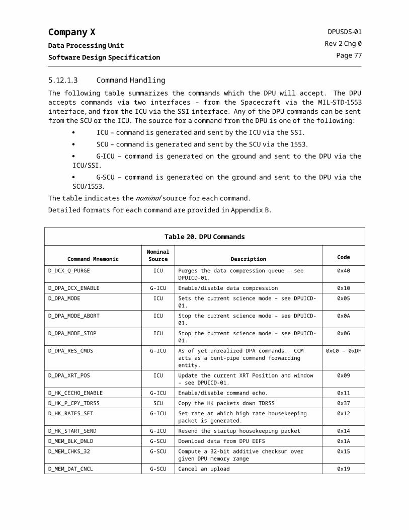
Company XData Processing UnitSoftware Design Specification
Table 24. TMALI CSC Global Data
Global Name Data Type Description Scope Create Read Write
numDciErrors UINT32 Running counters for error counts. CSC X X X
numDciTimeOuts UINT32 CSC X X X
numEventsLost UINT32 CSC X X X
numReportsLost UINT32 CSC X X X
ErrFlag BOOL Set to indicate that an error occurred reported by the DCI driver, used to ensure that error processing is postponed until data has been processed.
CSC X X X
dataFlag BOOL Set after data is received (from the DCI), cleared after data processing has completed.
CSC X X X
5.13.4 Error NumbersThe error conditions which are detected by this CSC are shown in the following table. The error numbers are defined in the CSC’s public header file. Some of the error numbers are used in various places in the tmali code, sequence numbers are used to distinguish between the different locations.
Table 25. TMALI CSC Error Numbers
Error Number Description
S_TMALI_DCI_ERR A DCI driver call was not completed successfully
S_TMALI_DCI_INIT_ERR The DCI port failed to open or initialize.
S_TMALI_DEFAULT_USED A call was made to the tmaliFrameDepthSet() function or the tmaliTask() was started with incorrect frame depth or buffer size parameters, the parameter was replaced by a defined default value.
S_TMALI_DEPTH_LOST A frame depth change request was not completed before a new frame depth change request was made, the initial request is lost and the new frame depth request becomes the current requested value.
S_TMALI_NO_DATA_AVAIL There was no data in the event queue when tmaliNextEvent() was called.
S_TMALI_NO_MEM TMALI failed to allocate the memory needed for the event queue.
S_TMALI_NOT_STARTED A call is made to one of the tmali API functions without first starting the tmaliTask() and thereby initializing the internal data structures.
S_TMALI_NULLPTR TMALI was passed a null pointer value.
S_TMALI_QUEUE_FULL The TMALI event queue is full – data has been lost.
S_TMALI_SEM_ERR Unexpected/unrecoverable semaphore error was reported by VxWorks
S_TMALI_WINDOW_ERROR A call was made to the tmaliDciWindowSet() function with incorrect window specification parameters.
DPUSDS-01Rev 2 Chg 0
Page 81

Company XData Processing UnitSoftware Design Specification
5.14 SCU Interface CSCThe SCU Interface (SCUI) CSC is a Level 3 reuse component from the INSTRUMENT Y project. The SCUI CSC is primarily responsible for implementing the application protocol with the SCU as defined in documents 1143-EI-S19121 and 1143-EI-S22904. The SCUI CSC provides CCSDS packetization services and manages the interface between the DPU and the SCU.The SCUI CSC includes the following components:
SCU Interface Task, scuiTask(), which accumulates Data Packages, converts them to CCSDS Version 1 Source Packets, forms Company X Telemetry Protocol Data Units (ST_PDUs) from the Source Packets, and transmits the ST_PDUs to the SCU via the MIL-STD-1553B Interface. The task also outputs messages to the “RT-RT” subaddress if one is awaiting on the input queue.
SCU Telemetry Enqueue function, scuiEnq(), which is an API by which other tasks provide telemetry data packages to the scuiTask() for processing.
SCU Observatory Message Enqueue function, scuiObsMsgSend(), which is an API by which other tasks provide command messages to the scuiTask() for transmission to the SCU and/or other Instruments (referred to in the 1553 ICD at “RT-RT Commands”.
SCU Interface Telemetry Done ISR, scuiTlmDoneISR(), which informs the DPU that the SCU has completed reading the prior ST_PDU, and gives a semaphore to awaken the scuiTask() to create and post a new ST_PDU.
SCU Interface Command Reader ISR, scuiReadCmdISR(), which receives Telecommands from the SCU and forwards them to the Command and Control Task for processing.
SCU Interface Housekeeping Function, scuiHkGet(), which gathers SCU Interface housekeeping data at the request of the Command and Control Task.
This CSC performs rate-buffering of the downlink telemetry to the SCU according to a commandable parameter. The rate at which the SCU polls the DPU is also commandable. The CSC installs an ISR to collect telecommands from the SCU via the MIL-STD-1553B Interface.
5.14.1 Structural DesignThis section contains the detailed structural diagrams which describe the design of this CSC.
5.14.1.1 InitializationThe SCUI CSC is initialized when the scuiTask() is spawned by the CCM CSC. Initialization parameters which are passed into the scuiTask() include: Poll Rate – rate at which the S/C will poll the DPU for telemetry. The rate is specified in Hz, and has a
default of X Hz based on the INSTRUMENT X-DPU poll rate in the Company X 1553 ICD. Buffer Rate – value used to rate buffer data to the S/C. The rate is specified in bits per telemetry poll, and has
a default of 7664 which is equal to one STPDU per poll (*** bytes per STPDU times V bits/byte). This default value effectively disables rate buffering.
Size of Low Priority Queue – size in bytes of the low priority telemetry queue. If the amount requested cannot be allocated, the buffer will be allocated at ½ the amount of memory contained in the largest free memory block.
Size of High Priority Queue – size in bytes of the high priority telemetry queue. If the amount requested cannot be allocated, the buffer will be allocated at ½ the amount of memory contained in the largest free memory block.
A structure chart for the scuiTask() function is shown in the following figure. The task invokes the initialization function scuiInit() which sets an instance variable, allocates ring buffers and semaphores for the Low and High Priority Telemetry Queues, initializes a buffer and semaphore for pending “RT-RT” command messages, creates
DPUSDS-01Rev 2 Chg 0
Page 82

Company XData Processing UnitSoftware Design Specification
the scuiTask() wakeup semaphore, initializes internal data structures, opens and initializes file descriptors for each of the required MIL-STD-1553 subaddresses and installs ISRs. When the CCM CSC spawns the scuiTask(), it will block on a semaphore (ccmSemScuiSpawn) awaiting SCUI initialization. Once initialization is complete, the SCUI CSC will signal successful initialization by giving the semaphore, and then write an empty STPDU to the 1553 shared memory.
scuiTask
scuiInit
scuiConvertToSTPDUscuiWritesemTake
SEM_IDscuiSemWakeUp
STATUS
semGive
SEM_IDccmSemScuiSpawn
scuiWrite
ccmTaskReport
scuiPurge
Figure 22. SCUI CSC, Structure Chart, scuiTask()
5.14.1.2 Transmitting Telemetry to the SpacecraftThe SCUI CSC receives telemetry as input Data Packages via queues populated by other tasks—the Science Data Processing Task, the Data Compression Task, and the Command and Control Task. The SCUI CSC has a High Priority Queue and a Low Priority Queue. The two queues are implemented in an identical manner with the exception that the scuiTask() gives processing preference to the High Priority Queue. The purpose of the High Priority Queue is to provide a means by which the Parameterized Finding Chart and DPU housekeeping can be transmitted to the SCU ahead of the potentially large amounts of buffered science data.
5.14.1.2.1 Telemetry Input to the SCUI CSCEach queue is implemented as a First-In First-Out (FIFO) buffer using the VxWorks® ring buffer library, rngLib. The calling application provides, via scuiEnq(), the data APID and processing information, a pointer to any tertiary header data (so-called since CCSDS packets already have a secondary header) and the length of that header data, and finally a pointer to the telemetry data itself and its length. The scuiEnq() function then enqueues a Data Package onto the appropriate queue as indicated in the PKG_CTRL field. Data Package identification and processing information is placed in a SCUI_ENTRY data structure, which is placed on the queue first, followed by the tertiary header (if present), followed by the telemetry data itself, and optionally followed by a trailing checksum (as indicated by the PKG_CTRL field) which is computed by scuiEnq(). The purpose of allowing the
DPUSDS-01Rev 2 Chg 0
Page 83

Company XData Processing UnitSoftware Design Specification
calling application to provide a separate pointer to tertiary header data is to eliminate the need for the caller to first copy the tertiary header data and the telemetry data to a separate single buffer prior to calling scuiEnq(), thus saving on memory copies. A structure chart for scuiEnq() is shown in the following figure.
scuiEnq
RING_IDSCUI_ENTRY *
sizeof(SCUI_ENTRY)
ccmErrEnq
ERRNO
semTake
SEM_ID
STATUS
STATUS
PKG_IDPKG_CTRL
UINT16 hdrLenchar *pHdrDataUINT16 pkgLenchar *pPkgData
rngBufPutrngBufPut rngBufPut rngBufPut
semGive
RING_IDchar *pHdrData
hdrLen
RING_IDchar *pPkgData
pkgLen
RING_IDchar * &cksum
sizeof(CHKS_16)
SEM_ID
Figure 23. SCUI CSC, Structure Chart, scuiEnq()
DPUSDS-01Rev 2 Chg 0
Page 84

Company XData Processing UnitSoftware Design Specification
5.14.1.2.2 Telemetry Output to the Spacecraft 1553 BusThe SCUI CSC reads the Data Packages from the queues and transforms them into CCSDS Version 1 Source Packets. These Source Packets are then packed into the STPDU for transmission to the SCU. This processing is performed by scuiConvertToSTPDU(). A structure chart for this function is provided in Figure 25. The STPDU, prefixed with a Transfer Request Counter (TRC), is then written to fifteen sequential 1553 subaddresses (as described in the Company X 1553 ICD) by the function scuiWrite(). The following figure illustrates the creation of a STPDU from the incoming Data Packages.
Pac
kage
IDP
acka
ge C
ontro
lB
yte
Cou
nt
Dat
a Pa
ckag
e
Raw
Dat
a &
Che
cksu
m
scuiHeaderBufferPackage ID Package Control Package Length
scuiDataBufferRaw Data
Incoming Data Packages
Source Packet Header TemplateVersion Number (3 bits)
Type Indicator (1 bit)Packet Secondary Header Flag (1 bit)Application Process Identifier (11 bits)
Grouping Flags (2 bits)Source Sequence Count (14 bits)
Packet Data Length (16 bits)Packet Secondary Header (6 bytes)
STPDU - 960 bytes
STPDU Transfer Request Counter2 bytes
STPDU Free Byte Slots958 bytes
Incoming Data Packages
Pending
Requests
Multiple D
ataP
ackages
Zero filled variable number oftrailing bytes
Packing Rules
Figure 24. SCUI CSC, Data Package to STPDU Conversion
DPUSDS-01Rev 2 Chg 0
Page 85

Company XData Processing UnitSoftware Design Specification
Figure 25. SCU Interface CSC, Structure Chart, scuiConvertToSTPDU()
The scuiConvertToSTPDU() function creates a complete STPDU for transmission each time the function is executed. The function calls scuiSTPDUFill() twice, once to populate the STPDU with data from the high priority queue, and then if space remains in the STPDU, it will attempt to populate the remaining space with data from the low priority queue. A flow chart for scuiSTPDUFill() is provided in Figure 26.The SCU, which is a MIL-STD-1553 Bus Controller (BC), periodically reads the STPDU contained in the fifteen telemetry subaddresses, and then writes to the “telemetry done” subaddress. When the “telemetry done” subaddress is written, the scuiTlmDoneISR() is called which gives a semaphore to awaken the scuiTask(). The software provides fault tolerance by automatically awaking after approximately two polling periods. This timeout is automatically adjusted any time the SCU Poll Rate value is changed by command.
DPUSDS-01Rev 2 Chg 0
Page 86

Company XData Processing UnitSoftware Design Specification
Figure 26. SCU Interface CSC, Flowchart, scuiSTPDUFill()
5.14.1.3 Receiving Commands from the SpacecraftThe DPU/SCU interface specifies that commands for the DPU will be transmitted from the SCU to the DPU on a separate MIL-STD-1553 subaddress. The SCU Interface Command Reader ISR, scuiCmdReadISR(). consists of an ISR installed on a specific MIL-STD-1553 subaddress corresponding to the command subaddress for the INSTRUMENT X DPU. This ISR is installed at initialization by scuiInit(). Upon interrupt, the scuiCmdReadISR() reads a single telecommand from the 1553 bus, checks the length and checksum, and then forwards valid commands to the Command and Control CSC for dispatch via ccmCmdEnq(). Errors are reported by incrementing an invalid command counter.
5.14.1.4 Sending Command Messages to the SpacecraftThe Instrument/SCU interface provides a mechanism by which an Instrument can transmit a message to the SCU or another Instrument via the SCU, formatted as a CCSDS Telecommand Packet. In this document, these messages are referred to as observatory messages. The scuiObsMsgSend() function provides an API by which an observatory message can be transmitted to the SCU via the 1553 bus. This function has an interface similar to scuiEnq(), except that this function attempts to write the message to the RT-RT subaddress immediately. If the SCU has not read the prior message yet, the prior message is removed from the 1553 shared memory and replaced with the new message, and an error (S_scui_OBSMSG_LOST) is enqueued to note that the prior message may not have been received by the S/C.
DPUSDS-01Rev 2 Chg 0
Page 87

Company XData Processing UnitSoftware Design Specification
Note: The Company X 1553 ICD does not specify a time, relative to any scheduled event, at which the SCU will read the RT-RT subaddress. Therefore, it is possible for the BC to read the RT-RT subaddress at the same time the DPU (which is the RT) is writing to the shared memory corresponding to that subaddress, resulting in a “collision”. The results of such a “collision” could be one or both of the following:
The BC reads a corrupted message containing an updated TRC but only a partially updated command packet.
The BC reads the RT-RT message but due to the collision the RT 1553 controller does not “see” the BC do it.
The SCUI CSC has been designed to avoid this problem as follows: when writing messages to the 1553 shared memory, the message is first written with an old TRC value, and then re-written with the new TRC value.
5.14.2 Public FunctionsThis section contains prototype-level descriptions of those functions which can be called from other CSCs. The functions are listed in alphabetical order.
5.14.2.1 scuiEnq() - Places data package in a queue
SynopsisSTATUS scuiEnq
(PKG_ID pkgID, PKG_CTRL pkgCtrl, UINT16 hdrLen,char *pHdrData,UINT16 pkgLenchar *pPkgData)
DescriptionThis routine places the given data in either the Low or High Priority Queue depending on the PKG_CTRL parameter. The PKG_CTRL parameter also controls whether or not the eventual CCSDS Source Packet can be segmented, and whether a trailing checksum should be computed.
ReturnsOK, or ERROR if the package is too large, the queue is full, or the mutual exclusion semaphore times out. Errors are reported directly to ccmErrEnq(), which also sets the errno global variable.
5.14.2.2 scuiHkGet() - Returns housekeeping data on the SCU Interface
Synopsisvoid scuiHkGet
(SCUI_HK *pHkBuf)
DescriptionThe routine gathers SCU CSC housekeeping data and returns a copy of it in the given buffer.
ReturnsN/A. Errors are reported directly to ccmErrEnq().
DPUSDS-01Rev 2 Chg 0
Page 88

Company XData Processing UnitSoftware Design Specification
5.14.2.3 scuiObsMsgSend() – Sends an observatory message to the SCU via 1553
SynopsisSTATUS scuiObsMsgSend
(PKG_ID pkgID,UINT8 fnCode,UINT16 cmdLen,char *pCmdData,int timeout)
DescriptionThe routine formats the given data into a CCSDS Telecommand Packet and writes it to the 1553 bus shared memory for transmission to the SCU. If a message is already pending in the 1553 shared memory, the pending messages will be replaced in 1553 shared memory with the new message, and an error will be reported.
ReturnsOK, or ERROR if the semaphore times out, the message has an incorrect length, or a shared memory write error occurs. Errors are reported directly to ccmErrEnq(), which also sets the errno global variable.
5.14.2.4 scuiRateSet() – Sets the SCU Poll Rate and SCU Buffer Rate to the given values
SynopsisSTATUS scuiRateSet
(UINT32 newPollRate,UINT32 newBufferRate)
DescriptionSets the poll rate and buffer rate to the given values. If the values are out of range, the prior values are retained and an error is reported. The scuiTask() semaphore timeout (scuiTaskTimeout) is automatically adjusted based on the given poll rate, by setting the timeout to approximately ½ the poll rate (not that the timeout is expressed in clock ticks, and so the resolution is low and only approximates ½ of the poll rate).
ReturnsOK, or ERROR if the values are out of range. Errors are reported directly to ccmErrEnq(), which also sets the errno global variable.
DPUSDS-01Rev 2 Chg 0
Page 89

Company XData Processing UnitSoftware Design Specification
5.14.2.5 scuiTask() - Entry point to the SCU Task
Synopsisvoid scuiTask
(UINT32 pollRate,UINT32 bufferRate,UINT32 lowPBufSize,UINT32 highPBufSize)
DescriptionThis routine is spawned by the Command and Control Task to initialize and execute the SCU Interface Data Processor Task. This task initializes the SCUI CSC and then enters an “infinite” loop to process telemetry and produce STPDUs. Once initialized, the task is awakened by a semaphore given when the SCU writes the “telemetry done” subaddress.
ReturnsNominally does not return. However, a convenience variable named scuiTaskRun can be set to FALSE to cause the task to exit and cleanup allocated resources.
5.14.3 Global DataThe following table lists the global data items which are accessed by this CSC, indicates whether the item is created, read, and/or written by this CSC, and defines the variable’s intended usage scope (Global=system-wide global, CSC=CSC-wide global). Scope as used in the table refers to the variables intended or logical scope. Variables which are global only to facilitate ground testing or potential on-board diagnostics are not listed here. The data types listed in the table are described in detail in the Data Dictionary.
Table 26. SCUI CSC Global Data
Global Name Data Type Description Scope Create Read Write
ccmSemScuiSpawn SEM_ID Used to confirm successful spawn of the SCUI task at startup.
Global X
scui1553_FD int [] Array of 1553 subaddress file descriptors.
CSC X X X
scuiClockTicks int Used to contain the system clock tick value to avoid repeated system calls.
CSC X X X
scuiEnqTimeout int Timeout value used in scuiEnq. CSC X X X
scuiHighPQueue SCUI_QUEUE SCUI high priority telemetry queue. CSC X X X
scuiLowPQueue SCUI_QUEUE SCUI low priority telemetry queue. CSC X X X
scuiObsMsgPendBuf UINT8 [] Buffer used to form up an RT-RT message.
CSC X X X
scuiStaticData SCUI_STATIC_DATA Static state data maintained and used by the SCUI CSC.
CSC X X X
DPUSDS-01Rev 2 Chg 0
Page 90

Company XData Processing UnitSoftware Design Specification
Table 26. SCUI CSC Global Data
Global Name Data Type Description Scope Create Read Write
scuiTaskTimeout int Value which controls timeout on the SCUI task. Is recalculated when the S/C polling rate is changed by command.
CSC X X X
5.14.4 Error ConditionsThe error conditions which are detected by the SCUI CSC are shown in the following table. These are reported in the DPU Housekeeping by making a call to the error-reporting function, ccmErrEnq().
Table 27. SCUI CSC Error Numbers
Error Number Description
S_scui_BAD_QUEUE The SCUI queue is corrupt and will be purged.
S_scui_BUFFER_RATE The new buffer rate is out of range – unchanged.
S_scui_CMD_CHKS A command received from the S/C had a bad checksum and was discarded. LSB contains the function code.
S_scui_CMD_LEN A command received from the S/C was not a multiple of 16-bit words and was discarded. LSB contains the function code.
S_scui_ENQ_TIMEOUT A Data Package could not be enqueued due to semaphore timeout.
S_scui_INIT_LOMEM The full buffer size could not be allocated – allocated ½ of available space. LSB contains location in code of error.
S_scui_INIT_NOMEM The SCU Interface failed to initialize when trying to allocate memory-bound resources. LSB contains location in code of error.
S_scui_INIT_PRIOR The SCU Interface was previously initialized.
S_scui_NULL_HK A NULL pointer was passed to the scuiHkGet() function.
S_scui_OBSMSG_LEN An outgoing observatory message was rejected since its length was not a multiple of 16-bit words. LSB contains the function code.
S_scui_OBSMSG_LOST An outgoing observatory message was purged from the 1553 shared memory since it was not read by the S/C in the expected timeframe.
S_scui_OBSMSG_TIMEOUT An outgoing observatory message was discarded due to a semaphore timeout.
S_scui_PKG_TOO_LARGE A task attempted to enqueue a Data Package larger than the maximum CCSDS packet size of C less secondary header size of 6 bytes.
S_scui_PKT_SEGMENTED A packet had to be segmented since it would not fit in a single STPDU.
S_scui_PKG_EMPTY A zero-length package was presented to scuiEnq() and discarded.
S_scui_POLL_RATE The new poll rate is out of range – unchanged.
S_scui_PURGE_TIMEOUT A semaphore timeout occurred while attempting to purge the SCUI queues. Queues were purged anyway.
S_scui_QUEUE_FULL The Data Package queue is full. LSB contains the queue ID (Low Priority Queue is 0, High Priority Queue is 1)
S_scui_QUEUE_PURGED The SCUI low priority queue has been purged.
S_scui_TASK_TIMEOUT The scuiTask was not awakened as expected at the expected interval.
S_scui_UNREAD_SA The indicated sub-address was not read by the SCU during the last poll period. LSB contains subaddress number.
S_scui_WRITE_ERROR An error occurred when writing data to the 1553 interface. LSB contains subaddress number.
DPUSDS-01Rev 2 Chg 0
Page 91

Company XData Processing UnitSoftware Design Specification
5.15 Data Compression CSCThe Data Compression (DCX) CSC was projected to be a Level 2 reuse component from the INSTRUMENT Y project at planning time. However, an alternate algorithm used on the XMM-OM project was benchmarked against the INSTRUMENT Y algorithm, and based on those benchmarks the XMM-OM algorithm was selected instead. As a result, the DCX CSC is now classified as a Level 3 reuse component, and will consist of some compression queue management code reused from INSTRUMENT Y, with compression algorithm code reused from XMM-OM.The Data Compression CSC consists of a Data Compression Task, dcxTask(), which accepts Data Packages from the DPA CSC via the dcxEnq() function, compresses them using the Variable Block Tiered Word Length (VBTWL) algorithm, and provides the compressed Data Package to the SCU Interface Data Processor Task
5.15.1 Structural DesignThe following sections describe the structural design of the Data Compression CSC.
5.15.1.1 InitializationThe DCX CSC is initialized when the dcxTask() is spawned by the CCM CSC. During initialization, the DCX CSC creates a compression queue to contain data packages which are pending compression. Access to the compression queue is protected by a mutual exclusion semaphore. The size of the compression queue is controlled by an initialization parameters which is passed into the dcxTask(). If the amount of memory requested cannot be allocated, initialization of the DCX CSC will fail.A structure chart for the dcxTask() function is shown in the following figure. The task invokes the initialization function dcxInit() which sets an instance variable, allocates the compression queue and mutual exclusion semaphore, creates the dcxTask() wakeup (data availability) semaphore, and initializes internal data structures. Once initialization is complete, the task enters an “infinite” loop to process data on the compression queue until the queue is empty or until pre-empted by another task. The task initially blocks on a binary “wakeup” semaphore which is given anytime new data is placed on the compression queue. If the compression queue is emptied, the task will again block on the semaphore until more data is available.
DPUSDS-01Rev 2 Chg 0
Page 92

Company XData Processing UnitSoftware Design Specification
Figure 27. DCX CSC, Structure Chart, dcxTask()
5.15.1.2 Data ProcessingThe DCX CSC is a task which receives data packages from other tasks, compresses the data using the VBTWL algorithm, and then forwards the compressed data package to the SCUI CSC.Data requiring compression is received via the dcxEnq() function, which has an API definition which matches the scuiEnq() API. The DCX CSC handles the PKG_CTRL flags as described below:
PKG_COMPRESS – this flag is set to indicate if the package is actually compressed. PKG_PRIORITY_HIGH – this flag is ignored by the DCX CSC but is forwarded to the SCUI CSC. PKG_SEGMENT – this flag is ignored by the DCX CSC but is forwarded to the SCUI CSC. PKG_CHECKSUM – if set, the dcxEnq() function will compute a checksum which is appended to the data, and then the flag is negated. The checksum will be compressed with the rest of the data, so that when the data is decompressed on the ground, the checksum can be recomputed and compared to provide a good indication of whether the decompressed copy of the data matches the original data set.
When the DCX CSC compresses a data package, the given APID is incremented by one. If the compressed copy of data is larger than original data set, the original data set will be forwarded to the SCUI CSC, an event S_dcx_UNC_USED is enqueued to ccmErrEnq(), and the APID is not incremented. In this way, the ground systems can discern compressed packets from non-compressed packets.
DPUSDS-01Rev 2 Chg 0
Page 93

Company XData Processing UnitSoftware Design Specification
5.15.1.3 Compression AlgorithmThe VBTWL algorithm is implemented in a set of C-language functions provided by UNIVERSITY A as a reuse item from the XMM-OM mission. The algorithm is described in document XMM-OM; therefore the design of the compression algorithm code itself is outside the scope of this document. Rather, the design of the code which “wraps” the algorithmic code is specified. The entry point to the compression algorithm is the function vbtwl(). This function is called directly by the Data Compression Task. The entry point for the Data Compression Task is the function dcxTask(). A structure chart for the Data Compression Task is shown in the following figure.
5.15.2 Public FunctionsThis section contains prototype-level descriptions of those functions which can be called from other CSCs. The functions are listed in alphabetical order.
5.15.2.1 dcxEnq() - Places data package in a queue
SynopsisSTATUS dcxEnq
(PKG_ID pkgID, PKG_CTRL pkgCtrl, UINT16 hdrLen,char *pHdrData,UINT16 pkgLenchar *pPkgData)
DescriptionThis routine places the given data in the data compression queue.
ReturnsOK, or ERROR if the package is too large, the queue is full, or the mutual exclusion semaphore times out. Errors are reported directly to ccmErrEnq(), which also sets the errno global variable.
5.15.2.2 dcxHkGet() – Return current housekeeping values
Synopsisvoid dcxHkGet
(DCX_HK *dcxHk)
DescriptionThis routine retrieves the current values for the DCX CSC housekeeping values and copies them into the given data structure. Counter values are reset to zero.
ReturnsN/A
DPUSDS-01Rev 2 Chg 0
Page 94

Company XData Processing UnitSoftware Design Specification
5.15.2.3 dcxTask() - Entry point to the Data Compression Task
Synopsisvoid dcxTask
(UINT32 dcxQueueSize /* Size of compression queue in bytes */)
DescriptionThis routine is spawned by the Command and Control Task to initialize and execute the DCX Data Compression Task. On startup, the task allocates the commanded amount of memory for the data compression queue, and creates the task semaphore.
ReturnsDoes not return.
5.15.3 Global DataThe following table lists the global data items which are accessed by this CSC, indicates whether the item is created, read, and/or written by this CSC, and defines the variable’s intended usage scope (Global=system-wide global, CSC=CSC-wide global). Scope as used in the table refers to the variables intended or logical scope. Variables which are global only to facilitate ground testing or potential on-board diagnostics are not listed here. The data types listed in the table are described in detail in the Data Dictionary.
Table 28. DCX CSC Global Data
Global Name Data Type Description Scope Create Read Write
dcxDPBuffer RING_ID Data compression data queue. CSC X X X
dcxDPBufferSem SEM_ID Data compression queue mutual exclusion semaphore.
CSC X X X
dcxHkBuffer DCX_HK Structure containing current HK values for retrieval at next HK poll.
CSC X X X
dcxPurgeFlag BOOL Set when the DCX queues should be purged, either in response to a command or as an error recovery action.
CSC X X X
dcxSemDataRdy SEM_ID Data compression task wakeup semaphore indicating data is available on the queue.
CSC X X X
5.15.4 Error NumbersThe error conditions which are detected by this CSC are shown in the following table. The error numbers are defined in the CSC’s public header file.
Table 29. DCX CSC Error Numbers
Error Number Description
S_dcx_ENQ_TIMEOUT A Data Package could not be enqueued due to semaphore timeout.
S_dcx_INIT_NOMEM The DCX CSC failed to initialize when trying to allocate memory-bound resources. LSB contains location in code of error.
DPUSDS-01Rev 2 Chg 0
Page 95

Company XData Processing UnitSoftware Design Specification
Table 29. DCX CSC Error Numbers
Error Number Description
S_dcx_INIT_PRIOR The DCX Interface was previously initialized.
S_dcx_NULL_HK A NULL pointer was passed to the dcxHkGet() function.
S_dcx_PKG_TOO_LARGE A task attempted to enqueue a Data Package larger than the maximum CCSDS packet size of 65536 less secondary header size of 6 bytes.
S_dcx_PURGE_TIMEOUT A semaphore timeout occurred while attempting to purge the DCX queues. Queues were purged anyway.
S_dcx_QUEUE_FULL The Data Package queue is full. LSB contains the queue ID (Low Priority Queue is 0, High Priority Queue is 1)
S_dcx_UNC_USED The non-compressed copy of the data was forwarded to SCUI since the compressed version of the data was larger than the original data set.
DPUSDS-01Rev 2 Chg 0
Page 96

Company XData Processing UnitSoftware Design Specification
5.16 Time Synchronization CSCThe Time Synchronization (TIS) CSC is a new component which provides services to maintain time synchronization between the DPU and the spacecraft, and which provides an API for retrieval of the current system time.
5.16.1 Structural DesignThe TIS CSC provides a library of functions to
initialize the DPU clock hardware at startup, maintain synchronization of the DPU clock with the Spacecraft clock, provide a function for use by other applications to retrieve the current values of the DPU clock and the UT Delta, and provide functions for use by the CCM command dispatcher to alter the configuration of the clock interface.
5.16.1.1 InitializationThe TIS CSC is initialized by calling the tisInit() function. The TIS CSC does not have an associated operating system task. The TIS CSC will initialize the DPU hardware to perform or not perform automatic time synchronization with the spacecraft as indicated by an initialization parameter passed to the tisInit() function. There are two 1 PPS signals between the DPU and the Spacecraft (a primary and alternate); the TIS CSC will select the active 1 PPS signal according to the parameter passed to the tisInit() function.
5.16.1.2 Time SynchronizationThe interface with the spacecraft as described in document 1143-EI-S19121 specifies that the spacecraft will provide a Clock Message to each Instrument at a 1 Hz rate. The Clock Message contains both two values: a value representing the current spacecraft time, and a value representing the delta from the spacecraft time and the Univeral Time (UT), based on an epoch of TBD. The time contained in the Clock Message is specified to be valid on the rising edge of the next 1PPS signal. When the DPU receives the Clock Message, the 1553 ISR calls the tisTimeSync() function, forwarding the data portion of the clock message to the TIS CSC via the TIS_CLK_MSG data structure.. The tisTimeSync() function will immediately copy the spacecraft clock value to the DPU clock hardware registers. The DPU hardware is designed to latch in the new time on the rising edge of the next 1 PPS signal (the act of writing a new time to the hardware registers “arms” the latch function in the hardware). Once the new time is latched, the hardware automatically disables the time latch function to avoid the potential of latching in an old time at the next 1 PPS signal.The UT Delta contained in the Clock Message is copied to a local static variable so that it can be provided to an application on request. To provide for mutual exclusion, the TIS CSC is designed to discard an incoming UT Delta if one or more applications are currently retrieving (copying) the prior UT Delta. A local static variable, tisUtDeltaCapture, is used to provide this mutual exclusion. A semaphore is not used since it the Clock Message is processed at interrupt context, and it is not valid for an ISR to take a semaphore. The static variable is effective since the variable is set by an application and tested by the ISR (i.e., there is no test-and-set). A more complicated mutual exclusion scheme is not warranted, since if a UT Delta is discarded a new UT Delta will be received within one second. In the unlikely event a UT Delta is discarded, an event message is enqueued to ccmErrEnq() for informational purposes.
DPUSDS-01Rev 2 Chg 0
Page 97

Company XData Processing UnitSoftware Design Specification
5.16.1.3 Time RetrievalThe DPU maintains a local copy of the spacecraft clock and current UT Delta in order that the DPU FSW can timestamp data products and packets. The TIS CSC provides a function, tisTimeGet(), which retrieves a copy of both the current DPU clock value and the most recent UT Delta value. Time is communicated among DPU FSW applications via the TIS_TIME data structure.
NOTE:THE TIS_TIME STRUCTURE CONTAINS A U-BIT COARSE TIME AND A 16-BIT FINE TIME.
HOWEVER, IF COPYING THE TIS_TIME STRUCTURE INTO ANOTHER STRUCTURE, USE THE CONSTANT TIS_TIME_SIZE, RATHER THAN sizeof(TIS_TIME), SINCE THE TIS_TIME STRUCTURE IS
PADDED TO EIGHT BYTES BY THE COMPILER.
5.16.1.4 Time Interface ConfigurationThe DPU hardware provides two configuration options to the software:
selection of the active A PPS signal, and the option to manually jam a value into the clock registers without the A PPS signal.
The TIS CSC provides three functions for use by the CCM command dispatcher to control these values: tis1ppsSet() – select active A PPS signal, tisSyncModeSet() – set whether manual clock jamming is enabled, and tisTimeSet() – manually jam a value into the DPU clock.
The TIS CSC utilizes the “manual jam” bit in the DCI CSR to indicate whether automatic time synchronization is enabled or disabled. If automatic time synchronization is enabled, and a command is issued to manually jam the DPU clock, the command will be rejected - see tisTimeSet().The bits to control the behavior of the DPU clock hardware were included in the DCI interface control/status register (CSR). This presents some opportunity for a mutual exclusion problem in the event these configuration settings are altered after startup. However, once initialized, both configuration settings are not expected to be altered. If they are, the DPU should be put into a mode whereby the DCI interface is quiescent.
5.16.2 Public FunctionsThis section contains prototype-level descriptions of those functions which can be called from other CSCs. The functions are listed in alphabetical order.
5.16.2.1 tis1ppsSet()
SynopsisSTATUS tis1ppsSet
(UINT32 which1PPS
DescriptionSelects the active A PPS signal according to the passed parameter.THIS FUNCTION ALTERS THE VALUE OF THE DCI CSR AND SHOULD NOT BE INVOKED WHEN DCI INTERRUPTS ARE ACTIVE.
ReturnsERROR if the commanded A PPS cannot be selected; OK otherwise.
DPUSDS-01Rev 2 Chg 0
Page 98

Company XData Processing UnitSoftware Design Specification
5.16.2.2 tisInit()
SynopsisSTATUS tisInit
(UINT32 which1PPS,BOOL autoSync)
DescriptionInitializes the TIS CSC by initializing the hardware register convenience pointers and selecting the commanded 1PPS signal, and enables or disables automatic time synchronization with the S/C according to the passed parameter.THIS FUNCTION ALTERS THE VALUE OF THE DCI CSR AND SHOULD NOT BE INVOKED WHEN DCI INTERRUPTS ARE ACTIVE.
ReturnsERROR if the commanded A PPS cannot be selected; OK otherwise.
5.16.2.3 tisSyncModeSet()
SynopsisSTATUS tisSyncModeSet
(BOOL autoSync)
DescriptionOperationally, the DPU uses the Jam bit in the DCI CSR to indicate whether the DPU is actively syncing its clock with the spacecraft or not. This function sets the Jam bit if autoSync is FALSE, and negates the Jam bit otherwise.THIS FUNCTION ALTERS THE VALUE OF THE DCI CSR AND SHOULD NOT BE INVOKED WHEN DCI INTERRUPTS ARE ACTIVE.
ReturnsERROR if the commanded A PPS cannot be selected; OK otherwise.
DPUSDS-01Rev 2 Chg 0
Page 99

Company XData Processing UnitSoftware Design Specification
5.16.2.4 tisTimeGet()
SynopsisSTATUS tisTimeGet
(TIS_TIME *sc_timeTIS_TIME *ut_delta)
DescriptionThis routine returns a copy of the local copy of the spacecraft time maintained in the DPU hardware, and the UT Delta from the most recent Clock Message which is maintained in a static variable. The caller may pass in NULL for either parameter. If NULL is passed for both parameters, the function performs no action and returns OK.
ReturnsOK.
5.16.2.5 tisTimeSet()
SynopsisSTATUS tisTimeSet
(TIS_TIME *sc_timeTIS_TIME *ut_delta)
DescriptionThis routine manually sets the values of the spacecraft time maintained in the DPU hardware, and the UT Delta maintained in a static variable, to the given values.
ReturnsERROR if the Jam bit is currently set in the DCI CSR, indicating that automatic time synchronization is enabled; OK otherwise.
5.16.2.6 tisTimeSync()
Synopsisvoid tisTimeSync
(TIS_CLK_MSG *clk_msg)
DescriptionThis routine extracts the current spacecraft time from the clock message and writes in to the hardware clock registers to be latched by the hardware at the next 1PPS signal, and maintains a copy of the UT Delta provided in the clock message. If the UT Delta is currently being copied by an application, the UT Delta from the current message is discarded and an event is enqueued to ccmErrEnq(). If automatic time synchronization is disabled, this routine returns with no action taken.THIS ROUTINE IS INVOKED AT INTERRUPT CONTEXT.
ReturnsN/A
DPUSDS-01Rev 2 Chg 0
Page 100

Company XData Processing UnitSoftware Design Specification
5.16.3 Global DataThe following table lists the global data items which are accessed by this CSC, indicates whether the item is created, read, and/or written by this CSC, and defines the variable’s intended usage scope (Global=system-wide global, CSC=CSC-wide global). Scope as used in the table refers to the variables intended or logical scope. Variables which are global only to facilitate ground testing or potential on-board diagnostics are not listed here. The data types listed in the table are described in detail in the Data Dictionary.
Table 30. TIS CSC Global Data
Global Name Data Type Description Scope Create Read Write
dciCsrReg UINT16 * Pointer to the DCI control/status register.
CSC X X X
scmSecsHiscmSecsLoscmSubSec
UINT16 * Pointer to the hardware timer registers.
CSC X X X
tisUtDelta TIS_TIME Holds the current UT Delta from the most recent Spacecraft Clock Message.
CSC X X X
tisUtDeltaCapture UINT32 Increments when an application begins copying the UT Delta value and decrements when an application has completed the copy.
CSC X X X
5.16.4 Error NumbersThe error conditions which are detected by this CSC are shown in the following table. The error numbers are defined in the CSC’s public header file.
Table 31. TIS CSC Error Numbers
Error/Event Number Description
S_tis_AUTO_MET_ENABLED Attemped to manually affect the value of the DPU clock when automatic time synchronization is enabled.
S_tis_BIT_FAIL Failed to set a bit in a hardware register.
S_tis_UTD_INUSE A new Spacecraft Clock Message arrived while an application was copying the UT Delta (information only).
5.17 ReservedThis section inserted in order to maintain section number synchronization with the SRS.
DPUSDS-01Rev 2 Chg 0
Page 101

Company XData Processing UnitSoftware Design Specification
5.18 Instrument Control Unit Interface CSCThe Instrument Control Unit Interface (ICUI) CSC is a new component that provides support for application-level communication with the INSTRUMENT X ICU. The ICUI CSC is primarily responsible for implementing the application protocol with the ICU as defined in document DPUICD-01. In order to meet these objectives, ICUI provides:
An ICU Interface Message Send Function, icuiEnq(), which provides an API by which other CSCs can send messages to the ICU. An ICU Interface Command Reader ISR, icuiCmdReceiveISR(), which receives Telecommands from the ICU and forwards them to the Command and Control Task for processing. An ICU Interface Housekeeping Function, icuiHkGet(), which gathers ICU Interface housekeeping data at the request of the Command and Control Task.
Communication, in the context of this design, is classified as either a message or a command. A message is defined as any communication entity sent from any DPU FSW task to the ICU FSW. A command is defined as any communication entity sent by the ICU FSW to the DPU FSW. These terms will be used in the remainder of this design section to distinguish directional communication between the ICU and DPU.
5.18.1 Structural DesignThe following sections illustrate and describe the design of the ICUI CSC.
5.18.1.1 InitializationThe ICUI CSC is initialized by calling icuiInit(). The icuiInit() function opens the SSI interface port to the ICU, installs the transmit and receive ISRs, and enables Transmit Message Mode in the SSI Driver CSC. The icuiInit() function is called by the CCM Control Task at bootup.
5.18.1.2 Sending Messages to the ICUIn order to send messages to the ICU, the DPU FSW tasks call icuiEnq(). The calling application passes the function code of the message to be sent, as well as a pointer to a data structure containing the message parameters associated with the given function code. The icuiEnq() function formats the message according to the ICU/DPU ICD using icuiMsgFormat(), and then writes the message to SSI Driver transmitter buffer by calling the driver write() function. A mutual exclusion semaphore, icuiSemWrite, protects the SSI Driver from being written by multiple tasks simultaneously. A timeout parameter lets the caller control how long it is willing to block on this semaphore if there is an access conflict. A structure chart for icuiEnq() is provided in the Figure 28.Some special processing and checking is required in this function to handle the transmission of the ACK/NAK message. When a command arrives from the ICU, the icuiCmdReceiveISR() will verify the message checksum and then send an ACK/NAK message to the ICU. It is possible that an application is in the midst of sending a message to the ICU at the time a command interrupt occurs. However, since it is not possible for an ISR to take a semaphore, an additional mechanism is required in order to provide mutual exclusion between a task an the ISR. To accommodate this problem, the icuiEnq() function first determines whether it is being invoked from interrupt context. If so, it then tests the value of a static variable, icuiEnqBusy. If the variable is set, the function will save the given ACK/NAK message parameters in static variables and return. If the variable is not set, the function will continue as normal (avoiding the semTake() and semGive() calls). In normal execution, the icuiEnqBusy variable is set on entry and negated on exit, after which the static variables containing the ACK/NAK message parameters will be checked to determine whether an ACK/NAK is pending. A flowchart describing the processing performed by icuiEnq() is provided in Figure 29.
DPUSDS-01Rev 2 Chg 0
Page 102

Company XData Processing UnitSoftware Design Specification
icuiEnq()
icuiMsgFormat() write()
ICUI_MSG *inBuf
STATUSsemTake() semGive()
SEM_ID
STATUSFN_CODE
UINT16 *outBuf
UINT16 *outBuf
STATUS
STATUSSEM_ID
Figure 28. ICUI CSC, Structure Chart, icuiEnq()
icuiMsgSend()
intContext()
icuiEnqBusy
icuiAckPending =TRUE
Save messageparameters
ISR Return
icuiEnqBusy =TRUE
Formatmessage
write()message
intContext()? icuiEnqBusy =FALSE
icuiAckPending
icuiAckPending =FALSE
semTake(icuiSemWrite)
icuiAckPending
Yes
Yes
No
Yes
No
No
No
Yes
Yes
Task ReturnNo
Figure 29. ICUI CSC, Flowchart, icuiEnq()
DPUSDS-01Rev 2 Chg 0
Page 103

Company XData Processing UnitSoftware Design Specification
Note in the flowchart that it is theoretically possible that an ACK/NAK could be pending when another command arrives from the ICU requiring another ACK/NAK. This should not occur, since by protocol the ICU should not send a second command until the first is acknowledged. However, if it were to occur, the function logic is such that the second command acknowledgement will be ignored, in which case the ICU will resend the command in accordance with the ICU/DPU protocol.
5.18.1.3 Receiving Commands from the ICUThe interface to the ICU is via a synchronous serial interface (SSI) bus, which utilizes an inter-block gap (IBG) to delineate complete messages from one another. The DPU hardware produces an interrupt when it detects an IBG, and the SSI Driver provides a mechanism by which an application can install an interrupt hook routine to respond to an IBG interrupt. Upon initialization, the ICUI CSC installs a hook routine into the SSI Driver called icuiCommandReceiveISR(), which verifies the checksum of an incoming command, transmits an ACK/NAK message to the ICU, and then enqueues the command for later processing by calling ccmCmdEnq(). A structure chart for the icuiCommandReceiveISR() function is shown in the following figure.
icuiCmdReceiveISR()
icuiEnq() ccmCmdEnq()
ICUI_MSG *msgParms
STATUS
FN_CODE
int timeout STATUS
chks8In16()
int
UINT8 * UINT16
ccmErrEnq()
ERRNO
Figure 30. ICUI CSC, Structure Chart, icuiCommandReceiveISR()
DPUSDS-01Rev 2 Chg 0
Page 104

Company XData Processing UnitSoftware Design Specification
5.18.2 Public FunctionsThis section contains prototypes of those functions that can be called from other CSCs. The functions are listed in alphabetical order.
5.18.2.1 icuiEnq()
SynopsisSTATUS icuiEnq
(FN_CODE functionCode,ICUI_MSG *msgParms,int timeout )
DescriptionThis routine is used to format messages for transmission to the ICU and to place those messages on the SSI Driver Transmitter Queue. The functionCode parameter is used to create the CCSDS Packet APID and the Message Identifier (refer to document DPUICD-01). A mutual exclusion semaphore, icuiSemWrite, protects the SSI Driver from being written by multiple tasks simultaneously. The timeout parameter lets the caller control how long it is willing to block on this semaphore if there is an access conflict.This routine may be called at interrupt context to transmit an ACK/NAK message. In that case, the semaphore is not taken since it is not valid to take a semaphore at interrupt context. Refer to discussion of the design to accommodate the ACK/NAK message.
ReturnsThis routine returns OK if the message is sent properly. If there is a problem sending the message, this routine returns ERROR and sets errno to one of the following values (see error table for detailed error descriptions):S_ssi_<ANY_SSI_ERROR>S_icui_Q_ORUNS_icui_SEM_TIMEOUTS_icui_NULL_POINTER
5.18.2.2 icuiHkGet()
SynopsisSTATUS icuiHkGet
(ICUI_HK *pHk)
DescriptionThis routines populates a ICUI_HK structure with the current housekeeping information.
ReturnsThis routine returns OK, or ERROR and sets errno if the passed parameter is NULL. The following error codes may be returned in errno (see error table for detailed error descriptions): S_icui_NULL_POINTER
DPUSDS-01Rev 2 Chg 0
Page 105

Company XData Processing UnitSoftware Design Specification
5.18.2.3 icuiInit()
SynopsisSTATUS icuiInit
(char * ssiName)
DescriptionThis routine initializes the interface to the ICU. This routine opens SSI Driver port, installs the SSI interface interrupt callbacks, and enables Transmit Message Mode in the SSI Driver.
ReturnsUpon successful initialization, this routine returns the file descriptor (ssi_fd) for DPU-SSI to the caller. If this routine cannot open or otherwise initialize DPU-SSI, or fails to properly set up the interface, it will return ERROR and set errno to one of the following:S_ssi_<ANY_ERROR>S_icui_SEM_CREATES_icui_NULL_POINTER
5.18.3 Global DataThe following table lists the global data items which are accessed by this CSC, indicates whether the item is created, read, and/or written by this CSC, and defines the variable’s intended usage scope (Global=system-wide global, CSC=CSC-wide global). Scope as used in the table refers to the variables intended or logical scope. Variables which are global only to facilitate ground testing or potential on-board diagnostics are not listed here. The data types listed in the table are described in detail in the Data Dictionary.
Table 32. ICUI CSC Global Data
Name Data Type Description Scope Create Read Write
icuiSSIFdCreated BOOL Indicates whether the SSI file descriptor has been created.
CSC X X X
icuiSSIfd Int Contains the SSI file descriptor. CSC x X
icuiMsgBuffer UINT16 Array[31] Buffer in which a message to the ICU is built up.
CSC X X X
5.18.4 Error NumbersThe error conditions which are detected by this CSC are shown in the following table. The error numbers are defined in the CSC’s public header file.
Table 33. ICUI CSC Error Numbers
Error Number Description
S_icui_CMD_BYTE_MISMATCH The command bytes reported available from SSI in fact couldn’t all be read.
S_icui_CMD_TOOBIG A command was received from SSI that was larger than allowed by the protocol.
S_icui_NO_DATA There is no data waiting on the queue requested, or data not yet available for function.
S_icui_NOT_INIT The ICUI module has not yet been initialized.
S_icui_NULL_POINTER A Null pointer was passed as a parameter when not allowed.
DPUSDS-01Rev 2 Chg 0
Page 106

Company XData Processing UnitSoftware Design Specification
Table 33. ICUI CSC Error Numbers
Error Number Description
S_icui_ODD_REQ A request was made to queue an odd amount of data. Only an even number of bytes may be transferred across the interface.
S_icui_PROTO_LEN_ERROR An enqueue of a message was attempted, but was unsuccessful because the caller specified a size that was out of range under the protocol governing this interface.
S_icui_Q_ORUN A queue has been overrun. Not able to enqueue requested data.
S_icui_SEM_CREATE A semaphore could not be created.
S_icui_SEM_TIMEOUT A semaphore has timed out; Most likely because the SSI Transmit queue was being written by another task.
S_ssi_<ANY ERROR> Any given SSI Error, if not handled by the ICUI CSC will be “bubbled” up to the caller. See the SSI Driver section for more information pertaining to these errors.
DPUSDS-01Rev 2 Chg 0
Page 107

Company XData Processing UnitSoftware Design Specification
5.19 Data Processing Algorithm CSCThe Data Processing Algorithm (DPA) CSC is a level 3 reuse component from XMM-OM which receives and processes INSTRUMENT X detector events, and produces science and engineering data products. The DPA CSC includes the following components:
Event Processor Task – communicates with the ICU, creates event list data products, creates Tracking Instrument Ys in the Ping/Pong buffers, creates the Finding Chart, performs the Engineering Modes, generates housekeeping data, creates the Event Frame, Ping and Pong buffers, and provides a task heartbeat to the CCM task. Instrument Y Processor Task – creates histogrammed Instrument Ys, performs Tracking (choose guide stars, drift correction, shift-and-add), creates the Reference, Accumulation, and Data Product buffers, and provides a task heartbeat to the CCM task. Event Frame buffer – holds time-tagged detector events before being compressed and sent to the spacecraft. Instrument Y buffers –
o Ping and Pong hold the X-second tracking Instrument Ys that are shifted and added to the Accumulation Instrument Y during tracking.
o Reference holds the initial X-second exposure that the guide stars are chosen from.
o Accumulation holds the final drift corrected Instrument Y.
o Data Product holds the final Instrument Y that will be compressed and sent to the spacecraft.
Algorithms –
o Choose Guide Stars scans the bright stars in the reference frame, chooses guide stars and sets up tracking windows around the guide stars.
o Drift Correction calculates the drift offset and roll of a just-completed tracking frame relative to the reference frame.
o Create Finding Chart will use the above Choose Guide Stars Algorithm to find the brightest stars in the finding chart Instrument Y then creates a list of the brightest stars and their intensities.
o Derive Channel Boundaries calculates a set of channel boundaries (18 numbers - 9X, 9Y) which are used by the centroiding software in the Blue Processing Electronics (BPE) in the Telescope Module.
5.19.1 Structural DesignThis section contains the detailed structural diagrams which describe the design of this CSC.
5.19.1.1 InitializationThe DPA CSC is initialized by spawning the tasks dpaEventTask() and dpaInstrument YTask(). After the tasks are spawned they create the needed memory buffers. The dpaEventTask() then enters the Idle state waiting for a Mode command from the ICU. The dpaInstrument YTask also enters the Idle state waiting to process either the Ping or Pong buffer. The default setting for compression (on or off) is retrieved from EEPROM.
5.19.1.2 Event ProcessingThe Event Processor Task, after receiving a Mode command from the ICU, configures the DPU DCI hardware, responds to the ICU with a Mode Ready message then receives detector events by calling functions tmaliWait()
DPUSDS-01Rev 2 Chg 0
Page 108

Company XData Processing UnitSoftware Design Specification
and tmaliNextEvent(). The Event Processor Task will collect detector events for the time period specified in the Mode command then issue a Mode Complete message to the ICU. After issuing the Mode Complete message, the Event Processor Task will enter the Idle state.If the Mode command is Event Mode, the detector events are spatially filtered to the event window specified in the Mode command then put into an event list in the Event Frame buffer. Once the Event Frame Buffer fills (4MB), or 5 seconds elapses, a PROD_EVENT data product will be produced and enqueued for transmission to the spacecraft.If the Mode command is Instrument Y Mode, the detector events are spatially filtered to the Instrument Y window specified in the Mode command then the corresponding pixel in the Ping or Pong buffer is incremented. If specified in the Mode command, pixels will be binned at AxA or BxB. Also, if specified in the Mode command, a tracking frame data product will be produced for every Ping/Pong tracking frame.Instrument Y and Event Mode may be commanded simultaneously in the Mode command.If the ICU sends an XRT Position command, the Instrument Y mode and Event Mode windows will be resized to match the new window sizes in the command. The Event Processor Task is also responsible for creating the Finding Chart. The Create Finding Chart Algorithm will use the Choose Guide Stars Algorithm to find the brightest stars in the finding chart Instrument Y. The parameterized finding chart will be created by listing the X & Y detector location of each star along with a CxC pixel matrix around the star location of the intensities.The Event Processor Task will create the necessary housekeeping for the DPA.The Event Processor Task also performs the following Engineering Modes:
5.19.1.2.1 Full-Frame (FF) Engineering ModeThe purpose of Full-Frame Engineering Mode is to monitor the health of the detector to locate hot spots and dead pixels.Detector events produced in Full Frame High Resolution detector format are received and histogrammed for a commanded integration time. The entire Instrument Y is transmitted to the ground. This mode can use high resolution (all pixels) or low resolution imaging (BxB , DxD pixel binning).
5.19.1.2.2 Raw Event List (RE) Engineering ModeThe purpose of Raw Event List Engineering Mode is to diagnose problems with the detector.Detector events produced in a given detector mode are collected over a commanded integration time and transmitted to the ground as a list of raw events.
5.19.1.2.3 Channel Boundary (CB) Engineering ModeThe purpose of Channel Boundary Mode is to derive the optimum channel boundary settings from a flat field.Detector events produced in the M,N detector mode are collected and histogrammed for a commanded integration time. The “pseudo Instrument Y” is transmitted to the ground. Channel boundaries are derived from the Instrument Y and transmitted to the ICU and the ground. Channel boundaries are sent by the ICU to the BPE and used in the detector event centroiding process
5.19.1.2.4 Centroiding Confirmation (CC) Engineering ModeThe purpose of Centroiding Confirmation Engineering Mode is to determine the validity of derived channel boundaries.Detector events are collected and histogrammed for a commanded integration time. The full field is divided into 8x8 sub-Instrument Ys, each of ExEcentroided (by 8) pixels. These sub-Instrument Ys are then modulo binned to
DPUSDS-01Rev 2 Chg 0
Page 109
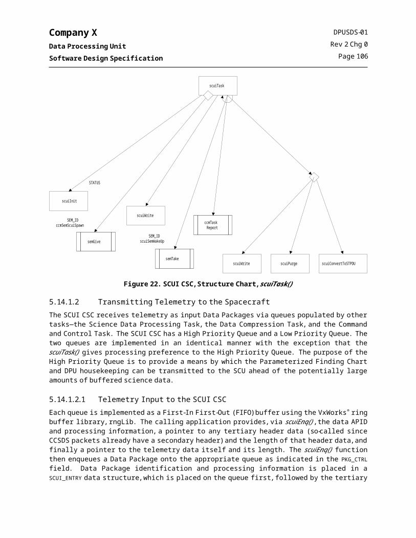
Company XData Processing UnitSoftware Design Specification
produce a set of 8x8 pixels pseudo-Instrument Ys. The Instrument Ys are column (y axis) ordered, as are the pixels within them. These pseudo Instrument Ys are transmitted to the ground.
5.19.1.2.5 Intensifier Characteristics (IC) Engineering ModeThe purpose of Intensifier Characteristics Engineering Mode is to assess detector health and performance.Detector events produced in Full Frame High Resolution detector format are collected and histogrammed for a commanded integration time to produce a pulse-height histogram.
Figure 26. DPA CSC, Structure Chart, dpaEPTask()
DPUSDS-01Rev 2 Chg 0
Page 110
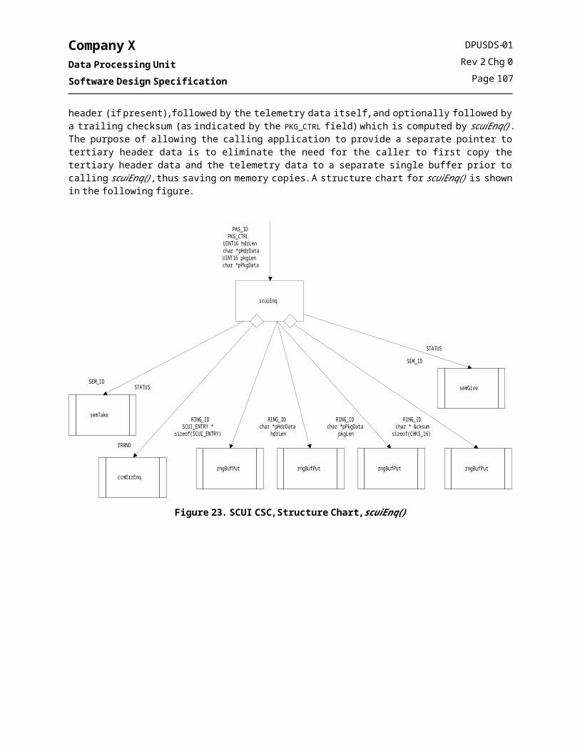
Company XData Processing UnitSoftware Design Specification
Figure 27. DPA CSC, Structure Chart, dpaEngineering()
Figure 28. DPA CSC, Structure Chart, dpaFindingChart()
5.19.1.3 Instrument Y ProcessingThe Instrument Y Processor Task will perform tracking by breaking the exposure up into 10-second sub-exposures which are shifted and added into a final histogrammed Instrument Y. Tracking is performed by choosing guide stars from the first 10-second Instrument Y of an exposure. Then in each subsequent Instrument Y, these guide stars are found and the drift is determined by comparing the two Instrument Ys. The Instrument Y is then shifted by the determined drift and added to the previous Instrument Ys in the accumulation buffer.
DPUSDS-01Rev 2 Chg 0
Page 111

Company XData Processing UnitSoftware Design Specification
An exposure starts by allowing the Event Processor task to complete the first Csecond tracking Instrument Y in the Ping buffer. This first tracking Instrument Y is copied to the reference frame buffer. The Choose Guide Stars function is called which tries to find guide stars in the reference frame. Bright sources in the reference frame are scanned and analyzed. The analysis gives a number of “quality” indicators for the bright sources. Based on these quality indicators and other global considerations such as star crowdedness, a number of guide stars, nominally 10, are selected. These star positions are saved for subsequent tracking. Based on the user-supplied/requested window configuration and the selected guide stars, window/memory management code configures memory windows and science windows around the guide stars to store acquired raw data. While tracking, the memory windows are shifted while obeying particular memory window restrictions. Those restrictions are: 1) that memory windows’ bottom left corner (BLC) coordinates are multiples of A and B that memory window sizes also are multiples of 16. These restrictions are imposed due to the requirements of event centroiding.After the guide stars are chosen, the Drift Correction algorithm looks at each subsequent Ping or Pong tracking frame. It calculates the drift offset and roll of a just-completed tracking frame relative to the reference frame. This is done by first calculating the position of the guide stars in the tracking frame. Then a maximum likelihood solution is found by comparing the positions of the guide stars calculated in the tracking frame with their position in the reference frame. Once the translation offset has been calculated, the tracking frame is shifted by the translation offset and added to the accumulation frame, which contains the previously accumulated tracking frames.At the end of an exposure, the Instrument Y in the accumulation buffer is transferred to the Instrument Y data product buffer one horizontal line at a time, starting at the top of the Instrument Y to form a PROD_INSTRUMENT Y data product. This ‘rasterized’ Instrument Y in the Instrument Y data product buffer will be enqueued for transmission to the spacecraft.
Figure 29. DPA CSC, Structure Chart, dpaIPTask()
DPUSDS-01Rev 2 Chg 0
Page 112

Company XData Processing UnitSoftware Design Specification
5.19.1.4 ACS Message ProcessingThe SCUI task will send the ACS message to the DPA by calling the function dpaACSReceive(). Because the SCUI task will be calling dpaACSReceive() from an ISR, dpaACSReceive() must return quickly. If commanded by the ICU in the Mode command, the ACS message will be saved along with the event data product. To return quickly, dpaACSReceive() will place the ACS message in a data queue then return. The Event Processor Task will remove the ACS messages from the queue and send them to the spacecraft.
Figure 30. DPA CSC, Structure Chart, dpaACSReceive()
5.19.2 Public FunctionsThis section contains prototype-level descriptions of those functions which can be called from other CSCs. The functions are listed in alphabetical order.
5.19.2.1 dpaModeCmd() – receive the Mode command from the ICU.
Synopsisvoid dpaModeCmd
(DPA_MODE_CMD *dpaModeCmd)
DescriptionThis routine provides a means for the CCM task to send a Mode command from the ICU to the DPA software. The Mode command shall be used to command the DPU into a particular science or engineering event processing mode. The mode shall become effective after the DPU has sent the Mode Ready message to the ICU.
ReturnsNone.
DPUSDS-01Rev 2 Chg 0
Page 113

Company XData Processing UnitSoftware Design Specification
5.19.2.2 dpaStopModeCmd() – receive the Stop Mode command from the ICU.
Synopsisvoid dpaStopModeCmd
(DPA_ICU_CMD *dpaStopModeCmd)
DescriptionThis routine provides a means for the CCM task to send the Stop Mode command from the ICU to the DPA software. The Stop Mode command shall be used to command the DPU to immediately stop processing events, complete the current data product, purge events from the DPU hardware, and enter Idle Mode. The data product will include the actual exposure time and the number of frames. In response to this command, the DPU shall issue a Mode Complete command to the ICU after finishing the before-mentioned tasks.
ReturnsNone.
5.19.2.3 dpaPurgCmpQueCmd() – receive the Purge Compression Queue command from the ICU.
Synopsisvoid dpaPurgCmpQueCmd
(DPA_ICU_CMD *dpaPurgCompQueCmd)
DescriptionThis routine provides a means for the CCM task to send a Purge Compression Queue command from the ICU to the DPA software. The Purge Compression Queue command shall be used to command the DPU to delete all data currently in the data compression queue.
ReturnsNone.
5.19.2.4 dpaPurgSciQueCmd() – receive the Purge Science Queue command from the ICU.
Synopsisvoid dpaPurgSciQueCmd
(DPA_ICU_CMD *dpaPurgSciQueCmd)
DescriptionThis routine provides a means for the CCM task to send a Purge Science Queue command from the ICU to the DPA software. The Purge Science Queue command shall be used to command the DPU to delete all data currently in the science telemetry output queue (i.e., data pending transmission to the spacecraft).
ReturnsNone.
DPUSDS-01Rev 2 Chg 0
Page 114

Company XData Processing UnitSoftware Design Specification
5.19.2.5 dpaXRTPosition() – receive the XRT position command from the ICU.
Synopsisvoid dpaXRTPosition
(DPA_XRT_POSITION_CMD *dpaXRTPositionCmd)
DescriptionThis routine provides a means for the CCM task to send the XRT Position command from the ICU to the DPA software. The XRT Position command shall be used to command the DPU to update the position and window parameters that it uses to spatially filter event data.
ReturnsNone.
5.19.2.6 dpaACSReceive() – receive the spacecraft’s ACS message.
Synopsisvoid dpaACSReceive
(ACS_MESSAGE *dpa_acs_message)
DescriptionThis routine provides a means for the SCUI task to send the spacecraft’s ACS message the DPA software. Note: THIS FUNCTION IS CALLED BY AN ISR AND MUST RETURN QUICKLY.
ReturnsErrors are reported to ccmErrEnq().
5.19.2.7 dpaHkGet() – send housekeeping.
Synopsisvoid dpaHkGet
(DPA_HK *dpa_hk)
DescriptionThis routine provides a means for the CCM task to get the housekeeping info from the DPA software. The CCM task will call this function and pass a pointer to the location that DPA is to store its housekeeping.
ReturnsNone.
DPUSDS-01Rev 2 Chg 0
Page 115

Company XData Processing UnitSoftware Design Specification
5.19.2.8 dpaDCXEnable() – report to DPA CSC whether data compression is on or off.
Synopsisvoid dpaDCXEnable
(BOOL)
DescriptionThis routine provides a means for the CCM to report to the DPA CSC whether to send data to the compression queue or directly to the spacecraft interface queue. After receiving a ground command to turn compression on or off, this function is called by the ccmCmdTask to inform the DPA whether to compress its data or not. This function will set the global variable dpa_dcx_on TRUE if compression is enabled and FALSE if not. Dpa_dcx_on will be used by the DPA to determine whether to send data to dcxEnq() or scuiEnq().
ReturnsNone.
5.19.2.9 dpaEPTask() – the DPA event processing task.
Synopsisvoid dpaEPTask
(void)
DescriptionThis routine is spawned by the Command and Control Task to initialize and execute the DPA Event Processing Task.
ReturnsDoes not return.
5.19.2.10 dpaIPTask() – the DPA Instrument Y processing task.
Synopsisvoid dpaIPTask
(void)
DescriptionThis routine is spawned by the Command and Control Task to initialize and execute the DPA Instrument Y Processing Task.
ReturnsDoes not return.
DPUSDS-01Rev 2 Chg 0
Page 116

Company XData Processing UnitSoftware Design Specification
5.19.3 Global DataThe following table lists the global data items which are accessed by this CSC, indicates whether the item is created, read, and/or written by this CSC, and defines the variable’s intended usage scope (Global=system-wide global, CSC=CSC-wide global). Scope as used in the table refers to the variables intended or logical scope. Variables which are global only to facilitate ground testing or potential on-board diagnostics are not listed here. The data types listed in the table are described in detail in the Data Dictionary.
Table 34. DPA CSC Global Data
Global Name Data Type Description Scope Create Read Write
dpa_dcx_on BOOL Indicates whether to compress data products or not.
Compress data = 1, Don’t compress data = 0
CSC X X X
dpa_Instrument Y_accum
UINT16 Global X X X
dpa_Instrument Y_ping
UINT16 Global X X X
dpa_Instrument Y_pong
UINT16 Global X X X
dpa_Instrument Y_ref UINT16 Global X X X
dpa_Instrument Y_telem
UINT16 Global X X X
5.19.4 Error NumbersThe error conditions which are detected by this CSC are shown in the following table. The error numbers are defined in the CSC’s public header file.
Table 35. DPA CSC Error Numbers
Error Number Description
S_dpa_ACCUM_MALLOC
S_dpa_DCI_ERROR_BITS1
S_dpa_DCI_ERROR_BITS2
S_dpa_DCI_SINGLE_TIME
S_dpa_EVENT_SEND
S_dpa_INSTRUMENT Y_PAR
S_dpa_INSTRUMENT Y_SEND1
S_dpa_INSTRUMENT Y_SEND2
S_dpa_INVALID_CMD_ID
S_dpa_INVALID_PP_STATE
S_dpa_INVALID_STATE1
S_dpa_INVALID_STATE2
S_dpa_INVALID_STATE3
S_dpa_MSGQ_ID
S_dpa_MSGQ_ISR
DPUSDS-01Rev 2 Chg 0
Page 117

Company XData Processing UnitSoftware Design Specification
Table 35. DPA CSC Error Numbers
Error Number Description
S_dpa_MSGQ_MEMORY
S_dpa_MSGQ_UNKNOWN
S_dpa_PING_MALLOC
S_dpa_PONG_MALLOC
S_dpa_PROD_MALLOC
S_dpa_REF_MALLOC
S_dpa_SCUI_ERROR1
S_dpa_SCUI_ERROR2
S_dpa_UNEXPECTED_ABORT
S_dpa_UNEXPECTED_MODE
S_dpa_UNEXPECTED_STOP
DPUSDS-01Rev 2 Chg 0
Page 118

Company XData Processing UnitSoftware Design Specification
6. DATA DICTIONARYThis section describes the abstract data types for the DPU FSW. The names of some items in this Data Dictionary match items in the Data Dictionary contained in the DPU SRS, document DPUSRS-01, but most do not because:
the SRS addresses interfaces at a higher, conceptual level whereas the design addresses interfaces the detailed implementation level, and the SDP specifies a set of coding conventions which require each abstract data type associated with a particular CSC, begin with an abbreviation of the name of that CSC.
The items in this dictionary include detail on the actual C language data types used. Composites are shown as C language structs. The Scope field indicates whether the data type is Private to the indicated module, or Public to other CSCs in the DPU FSW. Enumerations are typically shown as some integer form, followed by the constants which represent the valid values for the enumeration, except in cases where the C enumeration type is adequate to implement the data type. Abstract data types defined by VxWorks® are not reproduced in this table.
Table 36. Data Dictionary
Name Scope Type Definition Description
ACS_MESSAGE Global Typedef struct ACS_MESSAGE
{
} ACS_MESSAGE
Attitude CCSDS Telecommand Format
ADC_LIST_ENTRY Local typedef struct{UINT16 setupValue;ADC_VALUE *dataValue;} ADC_LIST_ENTRY;
Entries in the array of ADC values and multiplexer setup information maintained by the ADC Driver.
ADC_VALUE Global typedef UINT16 ADC_VALUE;
#define ADC_INVALID_VALUE 0x8000
#define ADC_SUSP_VALUE 0x4000
Type definition for the A/D values returned by the hardware. Only 12 bits are valid, with upper bits used to indicate invalid or suspect values as shown.
DPUSDS-01Rev 2 Chg 0
Page 119

Company XData Processing UnitSoftware Design Specification
Table 36. Data Dictionary
Name Scope Type Definition Description
CCM_CMD_PARMS Local Typedef union
{DPU_CMD_DATA rawData;C_SCUI_RATE scuiParms;C_HK_PERIODS hkPer;BOOL cmdEchoCtrl;BOOL hkTDRSSCopyCtrl;UINT16 tmaliSetting;UINT32 tis1PPS;UINT32 tisASCtrl;char shellCmd[52];UINT32 taskIdx;C_SYS_TASK_PTY taskIdx;C_SYS_MEM_CHKS32 memChks32;C_PCK_MEM_DAT_DNLD memDatDnld;C_NPCK_MEM_BLK_DNLD memBlkDnld;C_NPCK_MEM_DAT_UPLD1 memDatUpld1;C_NPCK_MEM_DAT_UPLD2 memDatUpld2;C_NPCK_MEM_DAT_POKE memDatPoke;
}
Union provided to map the data field in a CCM_DPU_CMD to actual command parameters used by specific commands.
CCM_DPU_CMD Local typedef struct{CCSCS_PRIMARY pktHdr;UINT8 pktType;UINT8 pktFcode;CCM_CMD_PARMS pktData;}
Structure provided to store and cast data coming from the command queue into a usable form with specific fields for correct parsing.
CCM_FIFO_ELT Local
(CCM)
typedef struct{DPU_CMD cmd}
Basic unit to be handled on ccm command queues.
CCM_FSM_STATUS Local
(CCM)
typedef UINT32
Bits:15 DCI Time Stamp FSM14 DCI Sync FSM (always 1)13 DCI Timeout FSM12 DCI Write FSM11 Zero Detection FSM10 1PPS FSM4 SSI Read Receive FSM3 SSI Receive FSM2 SSI Transmit/Write FSM1 SSI Transmit FSM0 ADC FSM
Composite memory area whose bits encode the operational status of the SCM State machines. If any of the bits listed to the left are zero when reported in the DPU Housekeeping, then something has gone wrong with the FSM that the bit encodes.
DPUSDS-01Rev 2 Chg 0
Page 120

Company XData Processing UnitSoftware Design Specification
Table 36. Data Dictionary
Name Scope Type Definition Description
CCM_STATIC_DATA Global
(CCM)
typedef struct{BOOL cmdEchoEnbl;BOOL hkSUSent;BOOL hkCopyTDRSS;UINT32 hkHRPeriod;UINT32 hkLRPeriod;UINT32 ccmTotNumErrs;UINT16 ccmTotalCmdCount;UINT16 ccmTotalCmdReject; UINT16 ccmDumpID;UINT8 ccmLastExecCmd;UINT8 ccmLastRejectCmd;} CCM_STATIC_DATA
Type definition for a control and management structure used by CCM to hold static data items needed to control CSC execution, special telemetry routes for large memory dumps, and housekeeping production.
CCSDS_PRIMARY Global typedef struct CCSDS_PRIMARY{UINT16 pktId;UINT16 pktSeqCtrl;UINT16 pktLen;} CCSDS_PRIMARY;
CCSDS Version 1 Source Packet Header structure.
CHKS_16 Global typedef UINT16 CHKS_16 16-bit checksum
CHKS_32 Global typedef UINT32 CHKS_32 32-bit checksum
CHKS_8 Global typedef UINT8 CHKS_8 8-bit checksum
DCI_CSR Local Register
Bits:
0: Arm Swap Enable1: Force Swap2: Acquisition Enable3: Pong Read4: Error INTR Enable5: Timeout INTR Enable6: Frame Limit INTR Enable7: Time Jam Enable8: Bit Arrangement 9: Error INTR Status10: One PPS Alternate11: Window Enable12: Test Select13: Timeout INTR Status14: Frame Limit INTR Status15: RESET ARM
DCI Register
DPUSDS-01Rev 2 Chg 0
Page 121

Company XData Processing UnitSoftware Design Specification
Table 36. Data Dictionary
Name Scope Type Definition Description
DCI_DEV Local typedef struct DCI_DEV{/* VxWorks OS device header */
DEV_HDR devHdr;
/* Physical Hardware Addresses */
UINT16 * pDciCSR;UINT16 * pDciSR; UINT16 * pDciTOR; UINT16 * pDciFRMLIMR; UINT16 * pDciAPINGHIR; UINT16 * pDciAPINGLOR; UINT16 * pDciAPONGHIR; UINT16 * pDciAPONGLOR; UINT16 * pDciRSTDR; UINT16 * pDciXWINR; UINT16 * pDciYWINR; UINT32 * pDciPPBuffer; /* Interrupt Slave interface */ int dciIntIRQ; UINT16 *pDciSCM_IMR; UINT16 *pDciSCM_IVR; UINT16 dciIntEnable; /* Internal Driver Variables */ SEM_ID dciSemDevLock; int dciMode; UINT32 dciTimerShadow;
/* User Hooks */
VOIDFUNCPTR dciErrISR; VOIDFUNCPTR dciFrmISR; VOIDFUNCPTR dciToISR; } DCI_DEV;
Descriptor block for the DCI hardware interface driver.
DCI_XY_HW_WIN Local Typedef struct DCI_XY_HW_WIN {
UINT8 x_max;UINT8 x_min;UINT8 y_max;UINT8 y_min;
} DCI_XY_HW_WIN
DCI hardware windowing settings
DCX_HK Global typedef struct{UINT32 queueDepth;UINT32 bytesCompressed;UINT32 avgCompRatio;} DCX_HK;
DCX CSC housekeeping data structure
DPUSDS-01Rev 2 Chg 0
Page 122
Company XData Processing UnitSoftware Design Specification
Table 36. Data Dictionary
Name Scope Type Definition Description
DPU_CNFG_PARMS Local
(CCM)
typedef struct{DPU_CTRL_STATUS
dpu_ctrl_word;UINT32 scu_poll_rate;UINT32 scu_buffer_rate;UINT32 scu_buffer_size;UINT32 tmali_pp_limit;UINT32 tmali_buffer_size;UINT32 dcx_buffer_size;} DPU_CNFG_PARMS;
DPU bootup default values structure.
DPU_CTRL_STATUS Local
(CCM)
Typedef UINT32 DPU_CTRL_STATUS;
#define TIS_SYNC_ENABLE 0x8#define DCX_ENABLE 0x10#define TIS_ALTERNATE_1PPS 0x100
Control word which selects the bootup value for various binary settings in the DPU.
ERRNO Global typedef UINT32 ERRNO
Bits:31-16: Module Number15-8: Error Number7-0: Error Supplemental Data
Error number
EVENT Global typedef UINT32 EVENT; Detector event data type.
FIFO_ID Local
(CCM)
Typedef UINT8 FIFO_ID The ID number for a ccm command queue
ICUI_HK Global typedef struct{UINT32 hkNMsgSent;UINT32 hkNMsgErrs;struct SSI_STAT ssiStatus;} ICUI_HK;
ICUI CSC housekeeping data structure
ICUI_MSG_HDR Local typedef struct {struct CCSDS_PRIMARY msgHdrCCSDS;TIS_TIME msgTime;} ICUI_MSG_HDR;
Format of message header for messages sent to ICU.
PKG Global typdef UINT16 PKG; This type is intended to be used as a pointer to the data buffer containing science or housekeeping data. Packets are required to be multiples of 16-bit entities.
PKG_CTRL Global typedef UINT8 PKG_CTRL;
#define PKG_COMPRESS 0x01/* Data is compressed */
#define PKG_PRIORITY_HIGH 0x02/* Data is high priority */
#define PKG_SEGMENT 0x04/* Data may be segmented */
#define PKG_CKSUM 0x08/* Package already has cksum */
Bit word used to control packetization and routing of data packages.
PKG_ID Global typedef UINT16 PKG_ID; Field used to create CCSDS Packet APID.
DPUSDS-01Rev 2 Chg 0
Page 123

Company XData Processing UnitSoftware Design Specification
Table 36. Data Dictionary
Name Scope Type Definition Description
SCUI_ENTRY Local typedef struct SCUI_ENTRY{PKG_ID pkgID;PKG_CTRL pkgCrtl;UINT16 pkgLen} SCUI_ENTRY;
Data structure which is enqueued into the SCUI data package queue to contain routing and processing information.
SCUI_HK Global typedef struct SCUI_HK{UINT32 currPollRate;UINT32 currBufferRate;UINT32 actLowPBufSize; UINT32 actHighPBufSize; UINT32 lowPBufDepth;UINT32 highPBufDepth;UINT32 bytesSent;UINT32 stpduSent;UINT32 cmdsReceived;UINT32 cmdsRejected;} SCUI_HK;
SCUI CSC housekeeping data structure.
SCUI_QUEUE Local typedef struct SCUI_QUEUE{RING_ID dataBuf;SEM_ID dataBufSem;SCUI_ENTRY inProcessEntry;UINT16 pkgBytesLeft;UINT8 id;} SCUI_QUEUE;
Structure to contain all the various data associated with the low/high priority SCUI queues.
SCUI_STATIC_DATA Local typedef struct{UINT32 bitBank;UINT32 tlmTRCValue;UINT32 cmdTRCValue;UINT32 currPollRate;UINT32 currBufferRate;UINT32 actLowPBufSize; UINT32 actHighPBufSize; UINT32 bytesSent;UINT32 stpduSent;UINT32 cmdsReceived;UINT32 cmdsRejected;UINT32 cmdsReceivedLastRptd; UINT32 cmdsRejectedLastRptd; BOOL purgeFlag;} SCUI_STATIC_DATA;
Structure to contain static information needed by the SCUI CSC.
DPUSDS-01Rev 2 Chg 0
Page 124

Company XData Processing UnitSoftware Design Specification
Table 36. Data Dictionary
Name Scope Type Definition Description
SSI_CSR Local Register
Bits:
0: Receive Enable1: Transmit Command2: Transmit Reset3: Receive Reset4: BGTX INTR Enable5: Error INTR Enable6: BGRX INTR Enable7: N/A8: Transmitter Empty9: Transmitter Full10: Receiver Empty11: Receiver Full12: BGTX INTR Status13: Error INTR Status14: BGRX INTR Status15: RESET
SSI Command Status Register
SSI_DEV Local Typedef struct SSI_DEV{TY_DEV ssi_tydev;
/* Byte Count Queues */ RING_ID ssiRngTxBCountID; /* Hardware Registers */ UINT16 *pSsiTxReg; UINT16 *pSsiRxReg; UINT16 *pSsiCSR; UINT16 *pSsiSR;
UINT16 *pSsiIBR; UINT16 *pSsiRSTSR;
/* Interrupt Slave interface */ int ssiIntIRQ; UINT16 *pSsiSCM_IMR; UINT16 ssiIntEnable; UINT16 *pSsiSCM_IVR; SEM_ID ssiSemMutex;SEM_ID ssiSemTxLock; struct SSI_STAT ssiStat;
} SSI_DEV;
Descriptor block for the SSI hardware interface driver.
DPUSDS-01Rev 2 Chg 0
Page 125

Company XData Processing UnitSoftware Design Specification
Table 36. Data Dictionary
Name Scope Type Definition Description
SSI_STAT Local Typedef struct SSI_STAT{/* Driver Mode */ BOOLstatBGTXMode; /* Byte Counters */ UINT32 statTxByteCount; UINT32 statRxTotByteCount; UINT32 statTxByteLimit;
UINT32 statRxTotByteCount; /* Event Counters */ UINT32 statNRxErrs;
UINT32 statNTxErrs;
UINT32 statNBGRXIntr; UINT32 statNBGTXIntr; UINT32 statNErrIntr; /* Hook addresses */ VOIDFUNCPTR statCbIbgRx; VOIDFUNCPTR statCbIbgTx; VOIDFUNCPTR statCbErr; } SSI_STAT;
SSI Driver status structure.
TIS_CLK_MSG Global typedef struct{UINT32 sc_sec;UINT32 utd_sec;UINT16 utd_subsec;} TIS_CLK_MSG;
Data portion of the Clock Message transmitted by the Spacecraft.
TIS_TIME Global Typedef struct{UINT32 tis_sec;UINT16 tis_ssec;} TIS_TIME;
Data structure used to communicate time between applications.
TMALI_EVENT_QUEUE Local typedef struct {EVENT *pToBuf,EVENT *pFromBuf,int bufSize,EVENT *pEventBuf} TMALI_EVENT_QUEUE;
Data structure which contains pointers to the ring buffer which implements the TMALI detector event queue.
TMALI_HK Global struct {TMALI_EVENT_QUEUE *tmali_queue,UINT32 queue_size,UINT32 queue_depth,UINT16 frame_depth,UINT16 data_timeout,UINT16 frame_orun_err_cnt,UINT16 swap_arm_err_cnt,UINT16 dci_status} TMALI_HK;
TMALI housekeeping data structure.
DPUSDS-01Rev 2 Chg 0
Page 126

Company XData Processing UnitSoftware Design Specification
DPUSDS-01Rev 2 Chg 0
Page 127

Company XData Processing UnitSoftware Design Specification
APPENDIX ADPU HOUSEKEEPING PACKET
DEFINITIONS
The paper copy of this document should have printouts of spreadsheet worksheets for each of theDPU Housekeeping Packets.
If viewed electronically, refer to file dpu_hk.xls, which should accompany this file.
DPUSDS-01Rev 2 Chg 0
Page A-1

Company XData Processing UnitSoftware Design Specification
APPENDIX BDPU COMMAND
DEFINITIONS
DPUSDS-01Rev 2 Chg 0
Page B-1
Company XData Processing UnitSoftware Design Specification
Purge Data Compression QueueMnemonic D_DCX_Q_PURGE
Command Information
Purges the data compression queue – see DPUICD-01
Nominal Source
ICU
Function Code 0x40
Command ParametersByte Parameter Description
0 No parameters
DPA Data Compression ControlMnemonic D_DPA_DCX_ENABLE
Command Information
Enable/Disable data compression
Nominal Source
G-ICU
Function Code 0x10
Command ParametersByte Parameter Description Parameter Values Range Units
0 Enable/Disable Control 0x00 = Disable0xFF = Enable
0x00 OR0xFF
BOOLEAN
Set the DPA Processing ModeMnemonic D_DPA_MODE
Command Information
Sets the current science mode – see DPUICD-1
Nominal Source
ICU
Function Code 0x05
Command ParametersByte Parameter Description
0-39 ICU MODE Parameters – see DPUICD-01
Abort the Current DPA Processing Mode
Mnemonic D_DPA_MODE_ABORT
Command Information
Forcefully abort the current science mode – see DPUICD-1
Nominal Source
ICU
Function Code 0x0A
Command ParametersByte Parameter Description
0 No Parameters
DPUSDS-01Rev 2 Chg 0
Page B-2

Company XData Processing UnitSoftware Design Specification
Stop the Current DPA Processing Mode
Mnemonic D_DPA_MODE_STOP
Command Information
Stop the current science mode – see DPUICD-1
Nominal Source
ICU
Function Code 0x06
Command ParametersByte Parameter Description
0 No Parameters
DPA Reserved Command Range
Mnemonic D_DPA_RES_CMDS
Command Information
Reserved command function code range for as of yet unrealized DPA commands. CCM Acts as a bent pipe command forwarding entity for these commands.
Nominal Source
G-ICU
Function Code 0xC0 – 0xDF
Command ParametersByte Parameter Description
0 Parameters are not checked. Parameters are defined by DPA.
Update DPA XRT position used by DPAMnemonic D_DPA_XRT_POS
Command Information
Update the current XRT Position and window – see DPUICD-01 for more information.
Nominal Source
ICU
Function Code 0x09
Command ParametersByte Parameter Description Parameter Values Range Units
0-1 UINT16 X location Range 0x0000 – 0x07FF Pixels
2-3 UINT16 Y location Range 0x0000 – 0x07FF Pixels
4-5 UINT16 X width Range 0x0000 – 0x07FF Pixels
6-7 UINT16 Y width Range 0x0000 – 0x07FF Pixels
DPUSDS-01Rev 2 Chg 0
Page B-3

Company XData Processing UnitSoftware Design Specification
Command Echo Housekeeping Control
Mnemonic D_HK_CECHO_ENABLE
Command Information
Enable or Disable Housekeeping Command Echo packet production
Nominal Source
G-ICU
Function Code 0x11
Command ParametersByte Parameter Description Parameter Values Range Units
0-3 UINT32 Enable/Disable Control
0x00000000 =Disable0xFFFFFFFF=Enable
0x00000000 OR0xFFFFFFFF
BOOLEAN
Copy Telemetry to TDRSS
Mnemonic D_HK_P_CPY_TDRSS
Command Information
Copy the HK packets down TDRSS
Nominal Source
SCU
Function Code 0x37
Command ParametersByte Parameter Description Parameter Values Range Units
0-3 UINT32 Enable/Disable Control
0x00000000 =Disable0xFFFFFFFF=Enable
0x00000000 OR0xFFFFFFFF
BOOLEAN
Set Housekeeping Packet Formation PeriodsMnemonic D_HK_RATES_SET
Command Information
Set the DPU rate of production for both High Rate and Low Rate Housekeeping packets. Rates are set as a time period interval.
The Low rate housekeeping period must be larger than the high rate housekeeping period. The high rate period must be less than or equal to the period set for the Heartbeat message to the ICU—currently X sec.
Nominal Source
G-ICU
Function Code 0x12
Command ParametersByte Parameter Description Parameter Values Range Units
0-3 UINT32 High Rate Period Range 0x00000000 – 0x0000000A Seconds
3-7 UINT32 Low Rate Period Range 0x0000000A – 0xFFFFFFFF Seconds
DPUSDS-01Rev 2 Chg 0
Page B-4

Company XData Processing UnitSoftware Design Specification
Send the Startup Housekeeping Packet
Mnemonic D_HK_START_SEND
Command Information
Resend the Startup housekeping packets. Packets are created at boot time. This command causes these packets to be resent.
Nominal Source
G-ICU
Function Code 0x14
Command ParametersByte Parameter Description
0 No Parameters
DPU Block Download
Mnemonic D_MEM_BLK_DNLD
Command Information
Read blocks of data from the DPU EEFS
Nominal Source
G-SCU
Function Code 0x1A
Command ParametersByte Parameter Description Parameter Values Range Units
0 UINT8 Reserved N/A N/A N/A
1 UINT8 Block ID Range 0x01 – 0x06 N/A
2-3 UINT16 Max Packet Size Range 0x00CD – 0x03A5 Bytes
4-5 UINT16 Path 0x0001= Stored0x0002= Real Time0x0003= TDRSS
N/A N/A
DPU EEPROM Filesystem Initialization
Mnemonic D_MEM_DISK_INIT
Command Information
Initialize disk EEFS
Nominal Source
G-SCU
Function Code 0x43
Command ParametersByte Parameter Description Parameter Values Range Units
0 N/A N/A N/A N/A
DPUSDS-01Rev 2 Chg 0
Page B-5

Company XData Processing UnitSoftware Design Specification
Compute a Checksum
Mnemonic D_MEM_CHKS_32
Command Information
Compute a 32-bit additive checksum over given DPU memory range
Nominal Source
G-SCU
Function Code 0x15
Command ParametersByte Parameter Description Parameter Values Range Units
0-3 UINT32 Address Start Range 0x00000000 – 0xFFFFFFFF Address
4-7 UINT32 Number of Bytes Range 0x00000000 – 0xFFFFFFFF Bytes
8-11 UINT32 Checksum Address
Range 0x00000000 – 0xFFFFFFFF Address
Cancel an Upload
Mnemonic D_MEM_DAT_CNCL
Command Information
Cancels an upload in progress.
Nominal Source
G-SCU
Function Code 0x19
Command ParametersByte Parameter Description Parameter Values Range Units
0 No parameters
Download Data from DPU Memory
Mnemonic D_MEM_DAT_DNLD
Command Information
Download data from DPU Memory. Science data collection may have to be halted if the requested size of the transfer is large.
Nominal Source
G-SCU
Function Code 0x16
Command ParametersByte Parameter Description Parameter Values Range Units
0-3 UINT32 Start Address Range 0x00000000 – 0xFFFFFFFF Address
4-5 UINT16 Byte Count Range 0x0000 – 0xFFFF Bytes
6-7 UINT16 Max Packet Size Range 0x00CD – 0x03A5 Bytes
8-9 UINT16 Path 0x0001 = Stored0x0002 = Real Time0x0003 = TDRSS
N/A N/A
DPUSDS-01Rev 2 Chg 0
Page B-6

Company XData Processing UnitSoftware Design Specification
Memory Poke Command
Mnemonic D_MEM_DAT_POKE
Command Information
Poke up to 43 bytes into DPU Memory
Nominal Source
G-SCU
Function Code 0x17
Command ParametersByte Parameter Description Parameter Values Range Units
0-3 UINT32 Reserved N/A N/A N/A
4-7 UINT32 Start Address Range 0x00000000 – 0xFFFFFFFF N/A
8 UINT8 Number of Bytes Range 0x00 – 0x2B Bytes
9-51 43 bytes of Data N/A N/A N/A
Memory Upload Command
Mnemonic D_MEM_DAT_UPLD
Command Information
The purpose of this command is to upload data to the DPU. This command is distinguished from the Memory Poke Commands in that it is used to upload larger amounts of data. Because of this larger amount of data, a sequence of Upload Commands are usually necessary to upload the data, and the data to be uploaded is typically contained in a file rather than as a direct command parameter. The DPU must determine data width and memory space by the address itself. The Upload Command is used for three purposes:
to upload data to one of the DPU memories, to upload data into one of the Instrument Data Blocks stored in the DPU
EEPROM filesystem, and to upload a software object file to the DPU EEPROM filesystem.
Nominal Source
G-SCU
Function Code 0x18
Command Parameters – This command takes two different
Byte Parameter Description Parameter Values Range Units
0-1 UINT16 Grouping Flags (2-bits) and Sequence Number (14-bits)
Seq Range
Grouping Flags: 01b = FIRST00b = CONT10b = LAST11b = SHORT
0x0000 – 0x3FFF (Sequence Count) N/A
2 UINT8 Reserved1 0 0x00 – 0x00 N/A
3 UINT8 Block ID Range 0x00 – 0x06 (0x00 = Raw Data) N/A
4-51 Data_1 – Data_48 N/A N/A N/A
DPUSDS-01Rev 2 Chg 0
Page B-7

Company XData Processing UnitSoftware Design Specification
Spacecraft Control ACS Message
Mnemonic D_SCUI_ACS_MSG
Command Information
Command carrying position information to instruments.
Dispatched in Interrupt context.
Nominal Source
SCU
Function Code 0x01
Command ParametersByte Parameter Description Parameter Values Range Units
0-3 UINT32 UTC Seconds Range 0x00000000 – 0xFFFFFFFF Seconds
4-5 UINT16 UTC Sub Seconds
Range 0x0000 – 0xFFFF Sub Seconds
6-7 UINT16 FILL N/A N/A N/A
8-11 UINT32 Observation Number
Observation SEG 8-bitsTarget ID 24-bits
Range 0x00000000 – 0xFFFFFFFF N/A
12-15 UINT32 Target ID (0x0 when not tracking a FoM requested target)
Range 0x00000000 – 0xFFFFFFFF N/A
16-23 (64-bit IEEE 754) Right Ascension (RA) of S/C
Range IEEE 754 specified Degrees J2000 Coord
24-31 (64-bit IEEE 754) Declination (DEC) of S/C
Range IEEE 754 specified DegreesJ2000 Coord
32-39 (64-bit IEEE 754) Roll of S/C (ROLL)
Range IEEE 754 specified DegreesJ2000 Coord
40-43 (32-bit IEEE 754) Latitude Range IEEE 754 specified Degrees
44-47 (32-bit IEEE 754) Longitude
Range IEEE 754 specified Degrees
48-51 (32-bit IEEE 754) Altitude Range IEEE 754 specified Meters
52-55 (32-bit IEEE 754) Bus Volltage
Range 0x00000000 – 0xFFFFFFFF Volts
56 UINT8 In SAA Flag 1=In SAA0=Not in SAA
1 or 0 BOOLEAN
57 UINT8 Is Settled, within 3 arcmin of target
1=Settled0=Not Settled
1 or 0 BOOLEAN
58 UINT8 In Safe mode 1=In Safe mode0=Not in Safe mode
1 or 0 BOOLEAN
DPUSDS-01Rev 2 Chg 0
Page B-8

Company XData Processing UnitSoftware Design Specification
Spacecraft Clock Command
Mnemonic D_SCUI_CLK_MSG
Command Information
This telecommand is sent to each instrument 900 to 500 ms before the next 1PPS signal is asserted.
This telecommand is dispatched in interrupt context.
Nominal Source
SCU
Function Code 0x02
Command Parameters Byte Parameter Description Parameter Values Range Units
0-3 UINT32 SCLK seconds value at the next 1PPS
Range 0x00000000 – 0xFFFFFFFF Seconds
4-7 INT32 Delta Seconds; delta is the difference between S/C Clock and UTC time
Range -2147483648 – 2147483647 Seconds
8-9 UINT16 Delta Sub Seconds; delta is the difference between S/C Clock and UTC Time
Range 0x0000 – 0xFFFF Sub Seconds
Set the SCUI Operational Rates
Mnemonic D_SCUI_RATES_SET
Command Information
Sets the expected spacecraft poll rate. Also sets the telemetry bit buffering rate to enforce.
Nominal Source
G-ICU
Function Code 0x21
Command ParametersByte Parameter Description Parameter Values Range Units
0-3 UINT32 Poll Rate Range 0x00000001 – 0x0000002B Hz
4-7 UINT32 Bit Buffer Rate Range 0x0000009A – 0x0005D8E0 bits/poll
Purge the SCUI Queue
Mnemonic D_SCUI_Q_PURGE
Command Information
Purge the SCUI Telemetry queue – see DPUICD-01
Nominal Source
ICU
Function Code 0x41
Command ParametersByte Parameter Description Parameter Values Range Units
0 No parameters
DPUSDS-01Rev 2 Chg 0
Page B-9

Company XData Processing UnitSoftware Design Specification
NOOP Command
Mnemonic D_SYS_NOOP
Command Information
Do nothing command used to test command path
Nominal Source
SCU
Function Code 0x24
Command ParametersByte Parameter Description Parameter Values Range Units
0 No parameters
Reboot DPU
Mnemonic D_SYS_REBOOT
Command Information
Reboot the DPU
Nominal Source
ICU/G-ICU
Function Code 0x42
Command ParametersByte Parameter Description Parameter Values Range Units
0 No parameters
Change a Task’s Priority
Mnemonic D_SYS_TASK_PTY
Command Information
Change a tasks priority
Nominal Source
G-ICU
Function Code 0x25
Command ParametersByte Parameter Description Parameter Values Range Units
0-3 UINT32 Task Number Range 0x00000000 – 0x0000000A N/A
4-5 UINT16 Task Priority Range 0x0000 – 0x00FF N/A
Resume Suspended Task
Mnemonic D_SYS_TASK_RESM
Command Information
Resume a suspended task
Nominal Source
G-ICU
Function Code 0x26
Command ParametersByte Parameter Description Parameter Values Range Units
0-3 UINT32 Task Number Range 0x00000000 – 0x0000000A N/A
DPUSDS-01Rev 2 Chg 0
Page B-10

Company XData Processing UnitSoftware Design Specification
Suspend Task
Mnemonic D_SYS_TASK_SUSP
Command Information
Suspend a task
Nominal Source
G-ICU
Function Code 0x27
Command ParametersByte Parameter Description Parameter Values Range Units
0-3 UINT32 Task Number Range 0x00000000 – 0x0000000A N/A
Execute a Shell Command
Mnemonic D_SYS_SHELL
Command Information
Issue a VxWorks Shell Command
Nominal Source
G-ICU
Function Code 0x28
Command ParametersByte Parameter Description Parameter Values Range Units
0-51 SHELL COMMAND N/A N/A N/A
Clear EEPROM Exception Information
Mnemonic D_SYS_EXC_CLEAR
Command Information
Clear Exception information from EDAC’s runtime exception table. Alternatively, exception values can be cleared from EEPROM and the EDAC interrupt can be enabled/disabled.
Nominal Source
G-ICU
Function Code 0x44
Command ParametersByte Parameter Description Parameter Values Range Units
0-3 UINT32 Clear EEPROM 0 = False1 = True
N/A BOOLEAN
4-7 UINT32 EDAC Enable 0 = Enable1 = Disable
N/A BOOLEAN
DPUSDS-01Rev 2 Chg 0
Page B-11

Company XData Processing UnitSoftware Design Specification
Select Time Synchronization 1PPS Source
Mnemonic D_TIS_1PPS_SELECT
Command Information
Select which 1PPS Source to use for TIS sychronization
Nominal Source
G-ICU
Function Code 0x30
Command ParametersByte Parameter Description Parameter Values Range Units
0-3 UINT32 which 1PPS 1=Primary 0=Alternate
N/A N/A
Control Automatic Clock Synchronization with spacecraft
Mnemonic D_TIS_SYNC_ENABLE
Command Information
Enable or Disable automatic clock synchronization with spacecraft
Nominal Source
SCU
Function Code 0x31
Command ParametersByte Parameter Description Parameter Values Range Units
0-3 UINT32 Enable/Disable 1=Enable 0=Disable
N/A BOOLEAN
Manually Jam the given time into DPU Clock
Mnemonic D_TIS_TIME_SET
Command Information
Manually jam the given time
Nominal Source
SCU
Function Code 0x32
Command ParametersByte Parameter Description Parameter Values Range Units
0-3 UINT32 Time Seconds Range 0x00000000 – 0xFFFFFFFF Seconds
4-5 UINT16 Time Sub Seconds
Range 0x0000 – 0xFFFF Sub Seconds
6-9 UINT32 Delta Seconds Range 0x00000000 – 0xFFFFFFFF Seconds
10-11 UINT16 Delta Sub Seconds
Range 0x0000 – 0xFFFF Sub Seconds
DPUSDS-01Rev 2 Chg 0
Page B-12

Company XData Processing UnitSoftware Design Specification
Set the TMALI Frame Limit
Mnemonic D_TMALI_DEPTH_SET
Command Information
Set the ping/pong or Frame Limit used by the DCI to trigger new data availability for TMALI
Nominal Source
G-ICU
Function Code 0x33
Command ParametersByte Parameter Description Parameter Values Range Units
0-1 UINT16 Depth Set Range 0x0001 – 0x0040 TMALI
Frames
Set the TMALI Timeout for DCI
Mnemonic D_TMALI_TO_SET
Command Information
Set the inactivity timer on the DCI hardware. The inactivity timer will expire if no new data has been received in this time period.
Nominal Source
SCU
Function Code G-ICU
Command ParametersByte Parameter Description Parameter Values Range Units
0-1 UINT16 Timeout Range 0x0000 – 0xFFFF Milliseconds
DPUSDS-01Rev 2 Chg 0
Page B-13


