download sae paper 2012-01-0700
TRANSCRIPT

ABSTRACTIn meeting the stringent emission norms with internal enginemeasures, the design of the piston bowl and the nozzleconfiguration perform a defining role. Through 3D CFDsimulations, this article shall parametrically investigate theinfluence of piston bowl geometry and nozzle characteristicson the performance of the combustion system. Aftervalidation of the 3D simulation model with experimentalresults, a Design of Experiment (DoE) method shall beapplied to analyze a matrix of piston bowls with parametricvariations in geometry. Further, the influence of the nozzlecone angle, hydraulic flow rate, number of holes and theircombination shall be determined using systematic parametervariations with selected piston bowl designs. Theperformance of the various hardware configurations would beevaluated based on the exhaust emissions and fuelconsumption values. The combustion system underconsideration is the Advanced Heavy Duty CombustionSystem (AHDCS) developed by FEV, which employs anarrow cone angle and a deeper piston bowl. Very high railpressures and highly cooled Exhaust Gas Recirculation(EGR) strategy shall be used to exploit the full potential ofthe combustion system. An understanding of thephenomenological behavior of the spray-bowl interactionbased on this parametric analysis would lay the groundworkfor further optimization of the combustion system.
INTRODUCTIONDiesel engines are undergoing a continuous process ofdevelopment to meet the increasingly stringent emission
legislations. The measures being taken to meet the legislativelimits are broadly divided into two groups, namely, internalmeasures and external measures. Internal measures directlyaffect the engine-out pollutants, while external measures areconcerned with the after-treatment of the exhaust gases. Thecombustion chamber geometry and the nozzle configurationsignificantly influence combustion and, thereby, the emissionformation and fuel consumption. Thus, they representimportant parameters for engine performance and the in-cylinder emission control strategy. They take on greatersignificance in the case of heavy duty engines, which have atraditionally low cylinder head swirl, with the mixturegeneration largely driven by the fuel spray jet and thecombustion chamber geometry. Hence, a detailedunderstanding of the influence of the piston bowl geometryand the nozzle parameters, as well as their combination, isnecessary to enable greater control of emission formation.Different piston bowl concepts have been proposed andimplemented over the years for high speed direct injectiondiesel engines /1/. Some prominent examples are the squarebowl chamber, the deep bowl design, the reentrant bowl andthe step bowl /1/. Similarly, the nozzle parameters, namely,the number of holes, hydraulic flow rate and the cone anglefall under the scope of optimization for engine development.Additionally, the start of injection has been included in theoptimization process, the importance of which has been re-iterated in recent publications /2, 3, 4/
A substantial amount of research has been performed in thepast in the field of combustion layout optimization. Most ofthe research takes into account the piston bowl geometry and
Parametric Analysis of Piston Bowl Geometry andInjection Nozzle Configuration using 3D CFD andDoE
2012-01-0700Published
04/16/2012
Vinod Karthik RajamaniFEV GmbH
Sascha Schoenfeld and Avnish DhongdeVKA, RWTH Aachen University
Copyright © 2012 SAE International
doi:10.4271/2012-01-0700
Gratis copy for Vinod RajamaniCopyright 2012 SAE International
E-mailing, copying and internet posting are prohibitedDownloaded Thursday, March 15, 2012 10:55:11 AM
nozzle cone angle. However, the nozzle parameters, holediameter and number of holes have not been included /5, 6, 7,8, 9/. Also, the analysis of a number of selected piston bowlgeometries have been considered without, however,parameterization of the profile /3//5//10//11/. A model-basedapproach has also been implemented for the purpose ofcombustion chamber optimization, with the use of GeneticAlgorithms (GA) /2//3//7//11/. To a large extent, in researchwhich includes the investigation of nozzle parameters, limitedfocus has been given to piston bowl shape /12/ Usually, thefocus of research is minimization of emissions from theengine. Also the achievement of a particular emission levelhas not been the objective /2//3//5//6//7/. Therefore, theviability of the different measures in real life applicationstowards fulfillment of emission norms is not clearlyunderstood. De Risi et al /7/ have extensively investigateddifferent combustion concepts using variation of piston bowlgeometry and injection cone angle. However, theoptimization been carried out for passenger car dieselengines, whose layout is not directly transferable to heavyduty diesel applications.
In this paper, the piston bowl geometry was parameterizedand analyzed, along with the nozzle geometry. A systematicapproach was adopted for the investigations, through acombination of 3D CFD simulations and the statisticaloptimization method, Design of Experiment (DoE). The 3DCFD simulations were performed using the code KIVA-3V.The ability of DoE in modeling influences of parameters overa large range with sufficient accuracy, while reducingcomputation time and effort has been demonstrated /13//14/.The statistical modeling and optimization were done with theaid of FEV's in-house program ProCal /15/. The combustionsystem chosen for the analysis is FEV's AHDCS /8//16//17/,described later in this work. The geometric parameters of thepiston bowl chosen for the analysis were the piston bowldiameter and the arc radius of the bowl. The nozzleparameters chosen were the number of holes, hydraulic flowrate (HFR) and cone angle. In addition, the start of injection(SOI) and nozzle tip protrusion (NTP) were varied to widenthe scope for optimization for the combustion system. Inaddition, a variety of thermodynamic and emissions relatedparameters were incorporated in the analysis. While theprimarily goal of the paper was the parametric analysis of thepiston bowl and nozzle geometry, the entire work scope wastargeted at combustion system optimization, in order tosatisfy the Tier 4 final NOx limits (0.4 g/kWh) for off-roadheavy duty diesel engines. To this end, high injectionpressures of 3000 bar were applied, along with high boostpressures and highly cooled EGR rates, in excess of 45% atrated power. The potential of such ultra-high injectionpressures in reduction of particulate matter emissions and fuelconsumption has been established on both, a single cylinderengine as well as a multi-cylinder engine /18//19/.
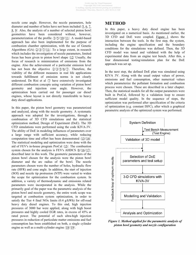
METHODIn this paper, a heavy duty diesel engine has beeninvestigated on a numerical basis. As mentioned earlier, the3D CFD and DoE were coupled. Figure 1 shows theinteraction between the tools. In the first step, the system,including the engine specification and the boundaryconditions for the simulations was defined. Then, the 3DCFD model was tuned and validated with the help ofexperimental data from an engine test bench. After this, afour dimensional testing/simulation plan for the DoEapproach was set up.
In the next step, the defined DoE plan was simulated usingKIVA 3V. Along with the usual output values of power,emissions and fuel consumption, other numerical valueswhich parameterize the pollutant formation and combustionprocess were chosen. These are described in a later chapter.Then, the statistical models for all the output parameters werebuilt in ProCal, followed by a validation loop to ensuresufficient model quality. In the sequence of steps, theoptimization was performed after specification of the criteriaof optimization (e.g. constant ISFC), after which a graphicalparametric analysis of the optimized system was performed.
Figure 1. Method applied for the parametric analysis ofpiston bowl geometry and nozzle configuration
Gratis copy for Vinod RajamaniCopyright 2012 SAE International
E-mailing, copying and internet posting are prohibitedDownloaded Thursday, March 15, 2012 10:55:11 AM
Based on the results of this DoE, two piston bowls werechosen for a more detailed full factorial optimization processof nozzle parameters, in order to satisfy Tier 4 final NOxlimits at acceptable particulate matter (PM) emission levelsand fuel consumption (FC). The parameters chosen were theNTP, HFR per nozzle hole and number of nozzle holes.
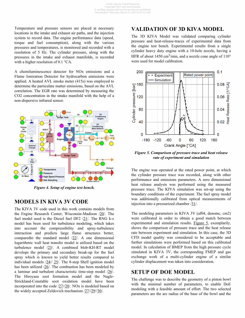
COMBUSTION CONCEPT AND TESTAPPARATUSThe combustion system used for the purpose of this analysisis FEV's Advanced Heavy Duty Combustion System(AHDCS). Compared to conventional combustion systems,AHDCS employs a narrower cone angle targeting deep intopiston bowl. The piston bowl design, without a re-entrant lip,is relatively simple with a more open shape. The narrow coneangle ensures the unidirectional flow of the fuel from near thecenter of the bowl outwards towards the cylinder head andliner. The main advantage of the AHDCS lies in reducedNOx emissions, resulting from the reduced air entrainment atthe beginning of combustion. Conversely, for a given NOxemission level, the SOI can be advanced or the EGR ratereduced, in comparison to a conventional combustion system.The combustion systems are compared schematically inFigure 2 /8/.
Figure 2. Concept comparison between AHDCS andconventional combustion
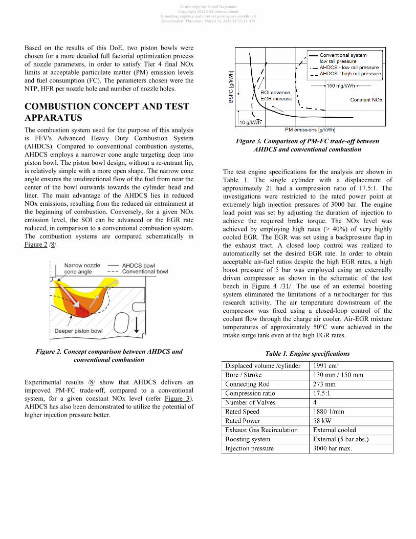
Experimental results /8/ show that AHDCS delivers animproved PM-FC trade-off, compared to a conventionalsystem, for a given constant NOx level (refer Figure 3).AHDCS has also been demonstrated to utilize the potential ofhigher injection pressure better.
Figure 3. Comparison of PM-FC trade-off betweenAHDCS and conventional combustion
The test engine specifications for the analysis are shown inTable 1. The single cylinder with a displacement ofapproximately 21 had a compression ratio of 17.5:1. Theinvestigations were restricted to the rated power point atextremely high injection pressures of 3000 bar. The engineload point was set by adjusting the duration of injection toachieve the required brake torque. The NOx level wasachieved by employing high rates (> 40%) of very highlycooled EGR. The EGR was set using a backpressure flap inthe exhaust tract. A closed loop control was realized toautomatically set the desired EGR rate. In order to obtainacceptable air-fuel ratios despite the high EGR rates, a highboost pressure of 5 bar was employed using an externallydriven compressor as shown in the schematic of the testbench in Figure 4 /31/. The use of an external boostingsystem eliminated the limitations of a turbocharger for thisresearch activity. The air temperature downstream of thecompressor was fixed using a closed-loop control of thecoolant flow through the charge air cooler. Air-EGR mixturetemperatures of approximately 50°C were achieved in theintake surge tank even at the high EGR rates.
Table 1. Engine specifications
Gratis copy for Vinod RajamaniCopyright 2012 SAE International
E-mailing, copying and internet posting are prohibitedDownloaded Thursday, March 15, 2012 10:55:11 AM
Temperature and pressure sensors are placed at necessarylocations in the intake and exhaust air paths, and the injectionsystem to record data. The engine performance data (speed,torque and fuel consumption), along with the variouspressures and temperatures, is monitored and recorded with aresolution of 5 Hz. The cylinder pressure, along with thepressures in the intake and exhaust manifolds, is recordedwith a higher resolution of 0.1 °CA.
A chemiluminescence detector for NOx emissions and aFlame Ionization Detector for hydrocarbon emissions wereapplied. A heated AVL smoke meter (415s) was employed todetermine the particulate matter emissions, based on the AVLcorrelation. The EGR rate was determined by measuring theCO2 concentration in the intake manifold with the help of anon-dispersive infrared sensor.
Figure 4. Setup of engine test bench.
MODELS IN KIVA 3V CODEThe KIVA 3V code used in this work contains models fromthe Engine Research Center, Wisconsin-Madison /20/. Thefuel model used is the Diesel fuel DF2 /21/. The RNG k-εmodel has been used for turbulence modeling, which takesinto account the compressibility and spray-turbulenceinteraction and predicts large flame structures better,comparedto the standard model /22/. A one dimensionallogarithmic wall heat transfer model is utilised based on theturbulence model /23/. A combined blob-KH-RT modeldevelops the primary and secondary break-up for the fuelspray which is known to yield better results compared toindividual models /24// 25/. The 8-step Shell ignition modelhas been utilized /26/. The combustion has been modeled bya laminar and turbulent characteristic time-step model /26/.The Hiroyasu soot formation model and the Nagle-Strickland-Constable soot oxidation model have beenincorporated into the code /27//28/. NOx is modeled based onthe widely accepted Zeldovich mechanism /27//29//30/.
VALIDATION OF 3D KIVA MODELThe 3D KIVA Model was validated comparing cylinderpressure and heat-release-traces of experimental data fromthe engine test bench. Experimental results from a singlecylinder heavy duty engine with a 10-hole nozzle, having aHFR of about 1450 cm3/min, and a nozzle cone angle of 110°were used for model calibration.
Figure 5. Comparison of pressure trace and heat releaserate of experiment and simulation
The engine was operated at the rated power point, at whichthe cylinder pressure trace was recorded, along with otherperformance and emissions parameters. A zero dimensionalheat release analysis was performed using the measuredpressure trace. The KIVA simulation was set-up using theboundary conditions of the experiment. The fuel spray modelwas additionally calibrated from optical measurements ofinjection into a pressurized chamber /31/.
The modeling parameters in KIVA 3V (af04, denomc, cm2)were calibrated in order to obtain a good match betweenexperimental and simulation results. Figure 5, exemplarily,shows the comparison of pressure trace and the heat releaserate between experiment and simulation. In this case, the 3DCFD model quality was considered to be acceptable andfurther simulations were performed based on this calibratedmodel. In calculation of BMEP from the high pressure cyclesimulated in KIVA 3V, the corresponding FMEP and gasexchange work of a multi-cylinder engine of a similarcylinder displacement was taken into consideration.
SETUP OF DOE MODELThe challenge was to describe the geometry of a piston bowlwith the minimal number of parameters, to enable DoEmodeling with a feasible amount of effort. The two selectedparameters are the arc radius of the base of the bowl and the
Gratis copy for Vinod RajamaniCopyright 2012 SAE International
E-mailing, copying and internet posting are prohibitedDownloaded Thursday, March 15, 2012 10:55:11 AM
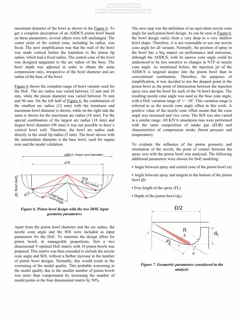
maximum diameter of the bowl as shown in the Figure 6. Toget a complete description of an AHDCS piston bowl basedon these parameters, several others were left unchanged. Thecenter point of the central cone, including its radius, wasfixed. The next simplification was that the wall of the bowlwas made vertical before the transition to the piston lipradius, which had a fixed radius. The central cone of the bowlwas designed tangential to the arc radius of the base. Thebowl depth was adjusted in order to obtain the samecompression ratio, irrespective of the bowl diameter and arcradius of the base of the bowl.
Figure 6 shows the complete range of bowl variants used forthe DoE. The arc radius was varied between 12 mm and 18mm, while the piston diameter was varied between 76 mmand 96 mm. On the left half of Figure 6, the combination ofthe smallest arc radius (12 mm) with the minimum andmaximum bowl diameter is shown, while on the right side thesame is shown for the maximum arc radius (18 mm). For thespecial combination of the largest arc radius (18 mm) andlargest bowl diameter (96 mm) it was not possible to have avertical bowl wall. Therefore, the bowl arc radius endsdirectly in the small lip radius (2 mm). The bowl shown withthe intermediate diameter is the base bowl, used for enginetests and the model validation.
Figure 6. Piston bowl design with the two DOE inputgeometry parameters
Apart from the piston bowl diameter and the arc radius, thenozzle cone angle and the SOI were included as inputparameters for the DoE. To maintain the design effort forpiston bowls in manageable proportions, first a twodimensional V-optimal DoE matrix with 16 piston bowls wasprepared. This matrix was then extended to include the nozzlecone angle and SOI, without a further increase in the numberof piston bowl designs. Normally, this would result in theworsening of the model quality. This probable worsening inthe model quality due to the smaller number of piston bowlswas more than compensated by increasing the number ofmodel points in the four dimensional matrix by 50%.
The next step was the definition of an equivalent nozzle coneangle for each piston bowl design. As can be seen in Figure 6,the bowl design varies from a very deep to a very shallowbowl shape. Therefore, it is not reasonable to use one nozzlecone angle for all variants. Normally, the position of spray inthe bowl has a big impact on performance and emissions,although the AHDCS, with its narrow cone angle could beunderstood to be less sensitive to changes in NTP or nozzlecone angle. As mentioned before, the injection jet of theAHDCS is targeted deeper into the piston bowl than inconventional combustion. Therefore, for purposes ofsimplification, it was decided to use the deepest point in thepiston bowl as the point of intersection between the injectionspray axis and the bowl for each of the 16 bowl designs. Theresulting nozzle cone angle was used as the base cone angle,with a DoE variation range of +/− 10°. This variation range isreferred to as the nozzle cone angle offset in this work. Apositive value of the nozzle cone offset meant that the coneangle was increased and vice versa. The SOI was also variedin a similar range. All KIVA simulation runs were performedwith the same composition of intake gas (EGR) andcharacteristics of compression stroke (boost pressure andtemperature).
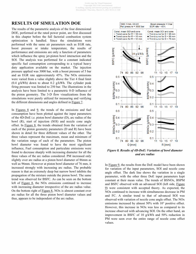
To evaluate the influence of the piston geometry andorientation of the nozzle, the point of contact between thespray axis with the piston bowl was analyzed. The followingadditional parameters were chosen for DoE modeling:
• Angle between spray and central cone of the piston bowl (α)
• Angle between spray and tangent to the bottom of the pistonbowl (β)
• Free length of the spray (FL)
• Depth of the piston bowl (db)
Figure 7. Geometric parameters considered in theanalysis
Gratis copy for Vinod RajamaniCopyright 2012 SAE International
E-mailing, copying and internet posting are prohibitedDownloaded Thursday, March 15, 2012 10:55:11 AM
RESULTS OF SIMULATION DOEThe results of the parametric analysis of the four dimensionalDOE, performed at the rated power point, are first discussedin this chapter before the full factorial combustion systemoptimization is handled. Since the simulations wereperformed with the same air parameters such as EGR rate,boost pressure or intake temperature, the results ofperformance and emissions are only a function of parameterswhich influence the spray jet-piston bowl interaction and theSOI. The analysis was performed for a constant indicatedspecific fuel consumption corresponding to a typical heavyduty application available on the market. The injectionpressure applied was 3000 bar, with a boost pressure of 5 barand an EGR rate approximately 45%. The NOx emissionswere varied from a value slightly above the Tier 4 final limit(0.4 g/kWh) down to about 0.2 g/kWh. The cylinder peakfiring pressure was limited to 250 bar. The illustrations in theanalysis have been limited to a parametric 0-D influence ofthe piston geometry. The 3-D flow visualizations from thesimulations were purely utilized for measuring and verifyingthe different dimensions and angles defined in Figure 7.
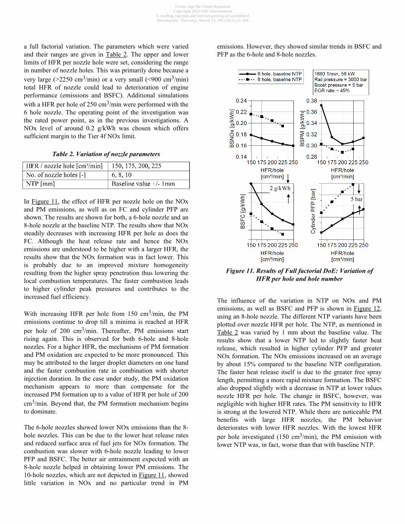
In Figures 8 and 9, the trends of the emissions and fuelconsumption have been plotted against the input parametersof the 4D-DoE i.e. piston bowl diameter (D), arc radius of thebowl (R), start of injection (SOI) and nozzle cone angleoffset. In Figure 8, the trends obtained from the variation ofeach of the piston geometry parameters (D and R) have beenshown in detail for three different values of the other. Thethree values represent the maximum, mean and minimum ofthe variation range of each of the parameters. The pistonbowl diameter was found to have the most significantinfluence, Fuel consumption and particulate emissions werefound to decrease sharply with increasing diameter for all thethree values of the arc radius considered. PM increased onlyslightly over arc radius at a piston bowl diameter of 86mm aswell as 96mm. However at piston bowl diameter of 76 mm, itincreased strongly with increasing arc radius. The probablereason is that an extremely deep but narrow bowl inhibits thepropagation of the mixture outside the piston bowl. The sametrend was observed for BSFC. As can be seen on the bottomleft of Figure 8, the NOx emissions continued to increasewith increasing diameter irrespective of the arc radius value.On the bottom right of Figure 8, NOx is almost constant overarc radius for all the three piston bowl diameter values andthus, appears to be independent of the arc radius.
Figure 8. Results of 4D-DoE: Variation of bowl diameterand arc radius
In Figure 9, the results from the DoE model have been shownfor variation of the input parameters, SOI and nozzle coneangle offset. The dark line shows the variation in a singleparameter, with the other three DoE input parameters keptconstant at their mean value. The trends of BSNOx, BSPMand BSFC observed with an advanced SOI (left side, Figure9) were consistent with accepted theory. As expected, theNOx continued to increase with simultaneous decrease in PMand FC. A similar trend to that of advanced SOI wasobserved with variation of nozzle cone angle offset. The NOxemissions increased by almost 50% with 10° positive offset.However, this increase in NOx was less as compared to itsincrease observed with advancing SOI. On the other hand, animprovement in BSFC of 10 g/kWh and 50% reduction inPM were seen over the entire range of nozzle cone offsetvalues.
Gratis copy for Vinod RajamaniCopyright 2012 SAE International
E-mailing, copying and internet posting are prohibitedDownloaded Thursday, March 15, 2012 10:55:11 AM

Figure 9. Results of 4D-DoE: Variation of SOI andnozzle cone offset
In Figure 10, the influence of the additional parameters viz. α,β, FL and db on both NOx and PM emissions are shown.With an increasing angle between the spray and the centralcone of the piston bowl, α, the NOx emission tends to reduce.Starting from an α value of approximately 1.5°, the NOxemission drops from well above 0.4 g/kWh to nearly 0.3g/kWh at an α of 6°. Further increase in α results in a furtherreduction in NOx at a lower rate. The PM emissionmarginally reduces with an α increase up to about 6°, afterwhich it rises slightly. Overall, the sensitivity of PM to α isrelatively low. Similarly, the correlation between PM and theangle between the spray and the tangent to the bottom of thepiston bowl, β, is also relatively low. On the other hand, NOxtends to steadily increase with incremental values of β.Beyond a value of about 45° for β, NOx begins to increaserapidly. Since β is also the complement of semi cone angle ofthe nozzle, it can be inferred that a semi cone angle nozzleless than 45° is not practical, with regard to NOx emission forthe given engine application. Higher values of spray free
length, FL, have a small but positive influence on PM. Adeeper piston bowl results in both, higher NOx and PMemissions. They increase by more than 50% when the bowlwidth, db, is increased from nearly 16 mm to 21 mm.
Figure 10. Influence of piston geometry on NOx and PMemissions
Moreover, the DoE model was used to make an optimizationof piston bowl design. Several optimization runs withdifferent weightings on targets as ISFC, NOx and PM wereperformed. The DoE model indicates that the largest bowldiameter, in combination with an arc radius of about 13 mmis useful for low soot-emission and fuel consumption. One ofthe 16 bowl designs, used, in the DoE modeling stage, with adiameter of 96 mm and an arc radius of 13.2 mm fitted thisdescription. Therefore, 3D CFD simulations were performedto validate the DoE model with this optimized piston bowland a satisfactory model quality was established. This pistonbowl was used as feedback to optimize the combustionsystem through the full factorial set of simulations.
RESULTS OF FULL FACTORIALCOMBUSTION OPTIMIZATIONIn order to investigate the effects of nozzle parameters, a fullfactorial design was chosen. As explained in the previouschapter, an optimized piston bowl (R = 13.2 mm, D = 96mm), obtained from the results of the four dimensional DoEwas applied for the combustion system optimization thesecond DoE. This DoE was performed in three dimensions as
Gratis copy for Vinod RajamaniCopyright 2012 SAE International
E-mailing, copying and internet posting are prohibitedDownloaded Thursday, March 15, 2012 10:55:11 AM
a full factorial variation. The parameters which were variedand their ranges are given in Table 2. The upper and lowerlimits of HFR per nozzle hole were set, considering the rangein number of nozzle holes. This was primarily done because avery large (>2250 cm3/min) or a very small (<900 cm3/min)total HFR of nozzle could lead to deterioration of engineperformance (emissions and BSFC). Additional simulationswith a HFR per hole of 250 cm3/min were performed with the6 hole nozzle. The operating point of the investigation wasthe rated power point, as in the previous investigations. ANOx level of around 0.2 g/kWh was chosen which offerssufficient margin to the Tier 4f NOx limit.
Table 2. Variation of nozzle parameters
In Figure 11, the effect of HFR per nozzle hole on the NOxand PM emissions, as well as on FC and cylinder PFP areshown. The results are shown for both, a 6-hole nozzle and an8-hole nozzle at the baseline NTP. The results show that NOxsteadily decreases with increasing HFR per hole as does theFC. Although the heat release rate and hence the NOxemissions are understood to be higher with a larger HFR, theresults show that the NOx formation was in fact lower. Thisis probably due to an improved mixture homogeneityresulting from the higher spray penetration thus lowering thelocal combustion temperatures. The faster combustion leadsto higher cylinder peak pressures and contributes to theincreased fuel efficiency.
With increasing HFR per hole from 150 cm3/min, the PMemissions continue to drop till a minima is reached at HFRper hole of 200 cm3/min. Thereafter, PM emissions startrising again. This is observed for both 6-hole and 8-holenozzles. For a higher HFR, the mechanisms of PM formationand PM oxidation are expected to be more pronounced. Thismay be attributed to the larger droplet diameters on one handand the faster combustion rate in combination with shorterinjection duration. In the case under study, the PM oxidationmechanism appears to more than compensate for theincreased PM formation up to a value of HFR per hole of 200cm3/min. Beyond that, the PM formation mechanism beginsto dominate.
The 6-hole nozzles showed lower NOx emissions than the 8-hole nozzles. This can be due to the lower heat release ratesand reduced surface area of fuel jets for NOx formation. Thecombustion was slower with 6-hole nozzle leading to lowerPFP and BSFC. The better air entrainment expected with an8-hole nozzle helped in obtaining lower PM emissions. The10-hole nozzles, which are not depicted in Figure 11, showedlittle variation in NOx and no particular trend in PM
emissions. However, they showed similar trends in BSFC andPFP as the 6-hole and 8-hole nozzles.
Figure 11. Results of Full factorial DoE: Variation ofHFR per hole and hole number
The influence of the variation in NTP on NOx and PMemissions, as well as BSFC and PFP is shown in Figure 12,using an 8-hole nozzle. The different NTP variants have beenplotted over nozzle HFR per hole. The NTP, as mentioned inTable 2 was varied by 1 mm about the baseline value. Theresults show that a lower NTP led to slightly faster heatrelease, which resulted in higher cylinder PFP and greaterNOx formation. The NOx emissions increased on an averageby about 15% compared to the baseline NTP configuration.The faster heat release itself is due to the greater free spraylength, permitting a more rapid mixture formation. The BSFCalso dropped slightly with a decrease in NTP at lower valuesnozzle HFR per hole. The change in BSFC, however, wasnegligible with higher HFR rates. The PM sensitivity to HFRis strong at the lowered NTP. While there are noticeable PMbenefits with large HFR nozzles, the PM behaviordeteriorates with lower HFR nozzles. With the lowest HFRper hole investigated (150 cm3/min), the PM emission withlower NTP was, in fact, worse than that with baseline NTP.
Gratis copy for Vinod RajamaniCopyright 2012 SAE International
E-mailing, copying and internet posting are prohibitedDownloaded Thursday, March 15, 2012 10:55:11 AM
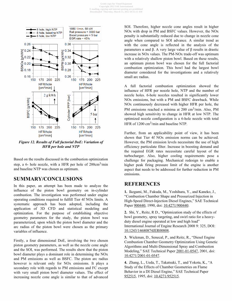
Figure 12. Results of Full factorial DoE: Variation ofHFR per hole and NTP
Based on the results discussed in the combustion optimizationstep, a 6- hole nozzle, with a HFR per hole of 200cm3/minand baseline NTP was chosen as optimum.
SUMMARY/CONCLUSIONSIn this paper, an attempt has been made to analyze theinfluence of the piston bowl geometry on in-cylindercombustion. The investigation was performed under engineoperating conditions required to fulfill Tier 4f NOx limits. Asystematic approach has been adopted, including theapplication of 3D CFD and statistical modeling andoptimization. For the purpose of establishing objectivegeometry parameters for the study, the piston bowl wasparameterized, upon which the piston bowl diameter and thearc radius of the piston bowl were chosen as the primaryvariables of influence.
Firstly, a four dimensional DoE, involving the two chosenpiston geometry parameters, as well as the nozzle cone angleand the SOI, was performed. The results show that the pistonbowl diameter plays a dominant role in determining the NOxand PM emissions as well as BSFC. The piston arc radiushowever is relevant only for NOx emissions. It plays asecondary role with regards to PM emissions and FC exceptwith very small piston bowl diameter values. The effect ofincreasing nozzle cone angle is similar to that of advanced
SOI. Therefore, higher nozzle cone angles result in higherNOx with drop in PM and BSFC values. However, the NOxpenalty is substantially reduced due to change in nozzle coneangle when compared to SOI advance. A similar trend aswith the cone angle is reflected in the analysis of theparameters α and β. A very large value of β results in drasticincrease in NOx values. The PM-NOx trade-off was optimumwith a relatively shallow piston bowl. Based on these results,an optimum piston bowl was chosen for the full factorialcombustion optimization. This bowl had the largest bowldiameter considered for the investigations and a relativelysmall arc radius.
A full factorial combustion optimization showed theinfluence of HFR per nozzle hole, NTP and the number ofnozzle holes. 6-hole nozzles resulted in significantly lowerNOx emissions, but with a PM and BSFC drawback. WhileNOx continuously decreased with higher HFR per hole, thePM emissions reached a minima at 200 cm3/min. Also, PMshowed high sensitivity to change in HFR at low NTP. Theoptimized nozzle configuration is a 6-hole nozzle with totalHFR of 1200 cm3/min and baseline NTP.
Further, from an applicability point of view, it has beenshown that Tier 4f NOx emission norms can be achieved.However, the PM emission levels necessitate the use of highefficiency particulate filter. Increase in boosting demand andthe required EGR rates necessitate careful layout of theturbocharger. Also, higher cooling requirements pose achallenge for packaging. Mechanical redesign to enable ahigher peak firing pressure limit of the engine is anotheraspect that needs to be addressed for further reduction in PMemissions.
REFERENCES1. Ikegami, M., Fukuda, M., Yoshihara, Y., and Kaneko, J.,“Combustion Chamber Shape and Pressurized Injection inHigh-Speed Direct-Injection Diesel Engines,” SAE TechnicalPaper 900440, 1990, doi: 10.4271/900440.
2. Shi, Y., Reitz, R D., “Optimization study of the effects ofbowl geometry, spray targeting, and swirl ratio for a heavy-duty diesel engine operated at low and high load”International Journal of Engine Research 2008 9: 325, DOI:10.1243/14680874JER00808.
3. Wickman, D., Senecal, P., and Reitz, R., “Diesel EngineCombustion Chamber Geometry Optimization Using GeneticAlgorithms and Multi-Dimensional Spray and CombustionModeling,” SAE Technical Paper 2001-01-0547, 2001, doi:10.4271/2001-01-0547.
4. Zhang, L., Ueda, T., Takatsuki, T., and Yokota, K., “AStudy of the Effects of Chamber Geometries on FlameBehavior in a DI Diesel Engine,” SAE Technical Paper952515, 1995, doi: 10.4271/952515.
Gratis copy for Vinod RajamaniCopyright 2012 SAE International
E-mailing, copying and internet posting are prohibitedDownloaded Thursday, March 15, 2012 10:55:11 AM
5. Lim, J. and Min, K., “The Effects of Spray Angle andPiston Bowl Shape on Diesel Engine Soot Emissions Using3-D CFD Simulation,” SAE Technical Paper 2005-01-2117,2005, doi:10.4271/2005-01-2117.
6. Hajireza, S., Regner, G., Christie, A., Egert, M. et al.,“Application of CFD Modeling in Combustion BowlAssessment of Diesel Engines Using DoE Methodology,”SAE Technical Paper 2006-01-3330, 2006, doi:10.4271/2006-01-3330.
7. de Risi, A., Donateo, T., and Laforgia, D., “Optimizationof the Combustion Chamber of Direct Injection DieselEngines,” SAE Technical Paper 2003-01-1064, 2003, doi:10.4271/2003-01-1064.
8. Herrmann, Ludger Ruhkamp, Körfer, Thomas, Pischinger,Stefan, Schönfeld, Sascha, “Possibilities for Optimization ofInjection Parameters to Improve Engine Performance ofHeavy Duty and Industrial Engines”, 11. Tagung “DerArbeitsprozess Des Verbrennungsmotors” 20./21. September2007
9. Richards, K., Subramaniam, M., Reitz, R., Lai, M. et al.,“Modeling the Effects of EGR and Injection Pressure onEmissions in a High-Speed Direct-Injection Diesel Engine,”SAE Technical Paper 2001-01-1004, 2001, doi:10.4271/2001-01-1004.
10. Zhu, Y., Zhao, H., Melas, D., and Ladommatos, N.,“Computational Study of the Effects of the Re-entrant LipShape and Toroidal Radii of Piston Bowl on a HSDI DieselEngine's Performance and Emissions,” SAE Technical Paper2004-01-0118, 2004, doi:10.4271/2004-01-0118.
11. Shi, Y. and Reitz, R., “Assessment of OptimizationMethodologies to Study the Effects of Bowl Geometry, SprayTargeting and Swirl Ratio for a Heavy-Duty Diesel EngineOperated at High-Load,” SAE Int. J. Engines 1(1):537-557,2009, doi:10.4271/2008-01-0949.
12. Su, T., Patterson, M., Reitz, R., and Farrell, P.,“Experimental and Numerical Studies of High PressureMultiple Injection Sprays,” SAE Technical Paper 960861,1996, doi: 10.4271/960861.
13. Besson, M., Hilaire, N., Lahjaily, H., and Gastaldi, P.,“Diesel combustion study at full load using CFD and Designof Experiments,” SAE Technical Paper 2003-01-1858, 2003,doi:10.4271/2003-01-1858.
14. O'Connor, J., White, C., and Charnley, M., “OptimisingCFD Predictions of Diesel Engine Combustion andEmissions Using Design of Experiments: Comparison WithEngine Measurements,” SAE Technical Paper 982458, 1998,doi: 10.4271/982458.
15. http://www.fev.com/data/documents/Spectrum_40_E_web.pdf
16. Körfer, Hermann, Ruhkamp, Schönfeld, Rajamani,Ehrly, Schönfeld, Hermann, Joyce, Nakagawa, Uchiyama,
Takeuchi: Combustion system strategy for emissionsreduction with ultra-high injection pressure for heavy dutyengines, 2010, Munich/Germany.
17. Pfeifer, Krüger, Grütering, Hermann, Schönfeld,Pischinger: NOx reduction measures on HD Diesel Engines,12. Aachener Kolloqium, 2003, Aachen/Germany.
18. Ishizuka et al, “Further Innovations for Diesel FuelInjection Systems: Closed-loop Control of Fuel Quantity by i-ART & Ultra High Injection Pressure”, 19th AachenerKolloqium 2010.
19. Ruhkamp, L, Herrmann, O et al “Further Options forDiesel Engine Improvements by Increased Injection Pressureup to 3000 bar”, 20th Aachener Kolloqium 2011.
20. Amsden, A.A.: KIVA-3V, RELEASE 2, Improvementsto KIVA-3V, Los Alamos National Laboratory ReportLA-13608-MS, 1999
21. Amsden, Anthony A., “KIVA-3: A KIVA Program withBlock-Structured Mesh for Complex Geometries”,LA-12503-MS, UC-361, March 1993.
22. Chiodi, M., An Innovative 3D-CFD-Approach towardsVirtual Development of Internal Combustion Engines, DOI:10.1007/978-3-8348-8131-1_1, © Vieweg+Teubner Verlag |Springer Fachmedien Wiesbaden GmbH 2011.
23. Reitz, R., “Assessment of Wall Heat Transfer Models forPremixed-Charge Engine Combustion Computations,” SAETechnical Paper 910267, 1991, doi:10.4271/910267.
24. Lee, Chang Sik et al, “An experimental and numericalstudy on fuel atomization characteristics of high-pressurediesel injection sprays”, Fuel 81 (2002) 2417-2423
25. Su, T., Patterson, M., Reitz, R., and Farrell, P.,“Experimental and Numerical Studies of High PressureMultiple Injection Sprays,” SAE Technical Paper 960861,1996, doi: 10.4271/960861.
26. Ricart, L., Xin, J., Bower, G., and Reitz, R., “In-CylinderMeasurement and Modeling of Liquid Fuel Spray Penetrationin a Heavy-Duty Diesel Engine,” SAE Technical Paper971591, 1997, doi: 10.4271/971591.
27. Heywood, J., “Internal Combustion EnginesFundamentals”, McGraw - Hill, 1988.
28. Han, Z., Uludogan, A., Hampson, G., and Reitz, R.,“Mechanism of Soot and NOx Emission Reduction UsingMultiple-injection in a Diesel Engine,” SAE Technical Paper960633, 1996, doi: 10.4271/960633.
29. Pischinger, S., Lecture notes, “Internal CombustionEngines I & II”, 3rd edition, RWTH-Aachen 2007
30. Miller, R., Davis, G., Lavoie, G., Newman, C. et al., “ASuper-Extended Zel'dovich Mechanism for Nox Modelingand Engine Calibration,” SAE Technical Paper 980781, 1998,doi: 10.4271/980781.
Gratis copy for Vinod RajamaniCopyright 2012 SAE International
E-mailing, copying and internet posting are prohibitedDownloaded Thursday, March 15, 2012 10:55:11 AM

31. Rajamani, Vinod, PhD Dissertation in progress, RWTHAachen University
CONTACT INFORMATIONVinod RajamaniFEV GmbHNeuenhofstrasse 18152078 [email protected]: +492415689809
ACKNOWLEDGMENTSThe authors would like to thank Mr. Job von Rango for hishelp and advice on DoE modeling.
DEFINITIONS/ABBREVIATIONS3D CFD
Three Dimensional Computational Fluid Dynamics
°CADegrees Crank Angle
αAngle between spray axis and central cone of piston
AHDCSAdvanced Heavy Duty Combustion System
βAngle between spray and tangent to the bottom of thepiston bowl
BMEPBrake Mean Effective Pressure
BSFCBrake Specific Fuel Consumption
BSNOxBrake Specific NOx
BSPMBrake Specific Particulate Matter emissions
dbDepth of piston bowl
DoEDesign of Experiments
EGRExhaust Gas Recirculation
FCFuel Consumption
FLFree Length of injection spray
FMEPFriction Mean Effective Pressure
HFRHydraulic Flow Rate of injection nozzle
HRRHeat Release Rate
ISFCIndicated Specific Fuel Consumption
λRelative air-fuel ratio
NOxNitrogen Oxide
NTPNozzle Tip Protrusion
PFPPeak Firing Pressure
PMParticulate Matter
SOCStart Of Combustion
SOIStart Of Injection
Gratis copy for Vinod RajamaniCopyright 2012 SAE International
E-mailing, copying and internet posting are prohibitedDownloaded Thursday, March 15, 2012 10:55:11 AM

The Engineering Meetings Board has approved this paper for publication. It hassuccessfully completed SAE's peer review process under the supervision of the sessionorganizer. This process requires a minimum of three (3) reviews by industry experts.
All rights reserved. No part of this publication may be reproduced, stored in aretrieval system, or transmitted, in any form or by any means, electronic, mechanical,photocopying, recording, or otherwise, without the prior written permission of SAE.
ISSN 0148-7191
Positions and opinions advanced in this paper are those of the author(s) and notnecessarily those of SAE. The author is solely responsible for the content of the paper.
SAE Customer Service:Tel: 877-606-7323 (inside USA and Canada)Tel: 724-776-4970 (outside USA)Fax: 724-776-0790Email: [email protected] Web Address: http://www.sae.orgPrinted in USA
Gratis copy for Vinod RajamaniCopyright 2012 SAE International
E-mailing, copying and internet posting are prohibitedDownloaded Thursday, March 15, 2012 10:55:11 AM