double tuned series hybrid active power filter … · for power quality improvement in distribution...
TRANSCRIPT

U.P.B. Sci. Bull., Series C, Vol. 79, Iss. 1, 2017 ISSN 2286-3540
DOUBLE TUNED SERIES HYBRID ACTIVE POWER FILTER
FOR POWER QUALITY IMPROVEMENT IN DISTRIBUTION
SYSTEM UNDER NON LINEAR LOAD CONDITIONS
Kumar Reddy CHEEPATI1, Sardar ALI2, Surya Kalavathi MUNAGALA3
The term power quality usually refers to voltage quality rather current
quality. Maintaining voltage quality is the responsibility of utilities and maintaining
current quality is the responsibility of the consumers connected to different loads.
The harmonic current due to the nonlinear loads flows through the system
impedance that causes disturbance to the voltage waveform. In this proposed
research, a series hybrid active power filter was designed to eliminate both current
and voltage harmonics. To eliminate current harmonics a double tuned filter was
designed and for elimination of voltage harmonics, series active filter was designed.
MATLAB simulation results validate that series hybrid active power filter can
eliminate both voltage and current harmonics in an effective manner as compared to
earlier techniques.
Keywords: Double Tuned Filter, Harmonics, Series Active Filter, Nonlinear
Load, Voltage Quality
1. Introduction
Concern about the power quality is increasing day by day as power system
becoming more complex and it is difficult to deliver good quality of power to
large loads. Power quality is one of the popular topics in the power industry since
the late 1980’s [1]. As per IEEE Recommendations for Power Quality standard
(IEEE Std 1159-2009), the Power quality is termed as “powering and grounding
sensitive load equipment in such a way that it is suitable for working of the
equipment [2]”. There are so many power quality issues like voltage sag, swell,
interruptions, transients, noise, voltage fluctuations, under voltage, over voltage,
DC offset, harmonics, inter harmonics, sub harmonics etc. Harmonics are the
integral multiples of fundamental frequency which causes due to the nonlinear
loads like power electronic devices, saturation devices, arc furnaces etc.
Harmonics are classified into positive sequence, negative sequence and zero
sequence components. Based on symmetry harmonics are classified as even and 1 Assist. Prof. & Research Scholar at JNTUK, Dept. of EEE, SVEC, Tirupathi, A.P, India, e-mail:
[email protected] 2 Prof., Dept. of EEE, RITS, Chevella, RR(Dt), Hyderabad, Telangana, A.P, India, e-mail:
[email protected] 3 Prof., Dept. of EEE, JNTU, Hyderabad, Telangana, A.P, India, e-mail: [email protected]

246 Kumar Reddy Cheepati, Sardar Ali, Surya Kalavathi Munagala
odd harmonics. Even harmonics cancels each other due to the symmetry of the
waveform. Odd Harmonics are classified into positive sequence, negative
sequence and zero sequence components. The positive sequence harmonics rotates
in the same direction as original balanced fundamental power supply. The order of
positive sequence harmonics is 1,7,13 etc., the negative sequence harmonics rotate
in the direction opposite to the original balanced fundamental power supply. The
order of negative sequence harmonics is 5, 11, 17 etc., the zero sequence
harmonics does not have any phase displacement and rotation. The order of zero
sequence harmonics are odd multiples of third harmonic frequency i.e 3,9,15 etc.
Many advances in power quality improvement has been taken place but most of
the techniques concentrated only on the elimination of current harmonics than
voltage harmonics. Voltage harmonics are one of the important power quality
issues which should be maintained purely sinusoidal to improve the power quality
at the utility side. Higher order current harmonics causes more distortion in
voltage wave form than lower order current harmonics. Current distortion mainly
caused due to the nonlinear loads but voltage distortion caused by the current
distortion and also by many other reasons like shunt capacitor switching,
resonance condition etc., reducing current harmonics does not mean that reducing
voltage harmonics in proportion to that. In general power quality refers to the
voltage quality since, maintaining voltage quality is very important for the utility
to meet the customer expectations. In this proposed research a double tuned shunt
passive filter was designed to reduce the current harmonics and series active
powers filter with instantaneous (or) p-q control technique was used to improve
the voltage waveform at the terminals of the supplying load. So, it must be
compulsory to solve the harmonic problems caused by that non-linear equipment
which are already installed at various locations. This proposed research paper is
divided into six chapters, Chapter-1 deals with introduction, Chapter-2 deals with
the block diagram of series hybrid active power filter, Chapter-3 deals with
mathematical model of double tuned shunt passive filter, Chapter-4 deals with the
design of series active power filter, Chapter-5 deals with results and discussions,
Chapter-6 deals with conclusions.
2. Topology of series hybrid active power filter
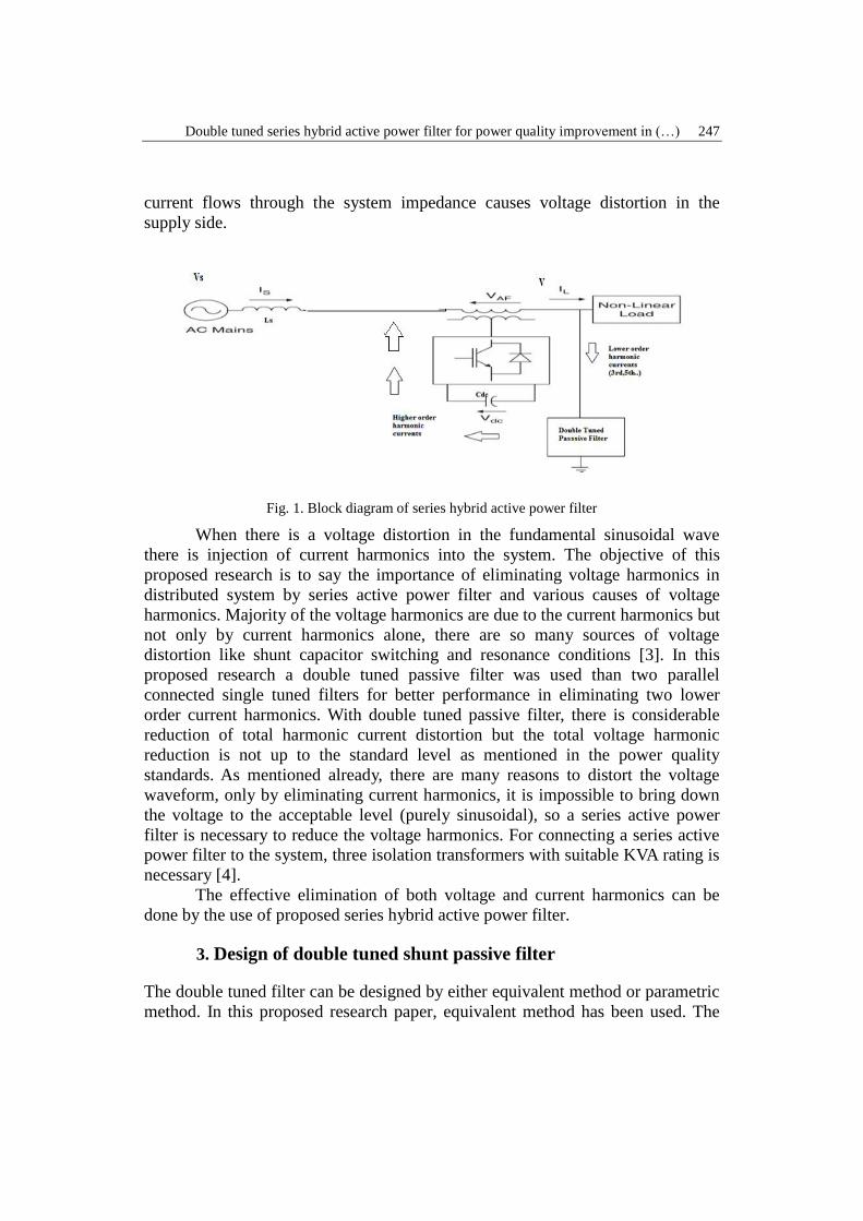
Fig. 1 shows the block diagram of series hybrid active filter. It consists of
a source which is connected to a nonlinear load (like bridge rectifiers, adjustable
speed drives, arc furnaces etc.), a double tuned shunt passive filter connected in
shunt with the system and a series active power filter with p-q control technique is
connected through coupling transformer. When a nonlinear load is connected to
the supply, it draws a non-sinusoidal current from the supply. This non-linear
Double tuned series hybrid active power filter for power quality improvement in (…) 247
current flows through the system impedance causes voltage distortion in the
supply side.
Fig. 1. Block diagram of series hybrid active power filter
When there is a voltage distortion in the fundamental sinusoidal wave
there is injection of current harmonics into the system. The objective of this
proposed research is to say the importance of eliminating voltage harmonics in
distributed system by series active power filter and various causes of voltage
harmonics. Majority of the voltage harmonics are due to the current harmonics but
not only by current harmonics alone, there are so many sources of voltage
distortion like shunt capacitor switching and resonance conditions [3]. In this
proposed research a double tuned passive filter was used than two parallel
connected single tuned filters for better performance in eliminating two lower
order current harmonics. With double tuned passive filter, there is considerable
reduction of total harmonic current distortion but the total voltage harmonic
reduction is not up to the standard level as mentioned in the power quality
standards. As mentioned already, there are many reasons to distort the voltage
waveform, only by eliminating current harmonics, it is impossible to bring down
the voltage to the acceptable level (purely sinusoidal), so a series active power
filter is necessary to reduce the voltage harmonics. For connecting a series active
power filter to the system, three isolation transformers with suitable KVA rating is
necessary [4].
The effective elimination of both voltage and current harmonics can be
done by the use of proposed series hybrid active power filter.
3. Design of double tuned shunt passive filter
The double tuned filter can be designed by either equivalent method or parametric
method. In this proposed research paper, equivalent method has been used. The

248 Kumar Reddy Cheepati, Sardar Ali, Surya Kalavathi Munagala
conventional double tuned filter is as shown in Fig. 2. It is having a series
resonant and shunt resonant circuit [3].
Fig. 2. Double tuned passive filter & equivalent single tuned passive filters
It can filter two lower order (3rd, 5th, 7th etc.) harmonics with a single circuit
whereas for single tuned, it requires two separate parallel circuits. The series
circuit gives series resonant frequency ( sw ) and parallel circuit gives parallel
resonant frequency ( pw ). These two resonance frequencies can filter two
dominant lower order current harmonics from the power system with single
circuit. Double tuned passive filter gives better performance when compared to
the two single tuned passive filters [4]. In this proposed research, by using
parameters of two single tuned filters, the double tuned filter was designed. At
resonant frequencies, the reactance of inductor is equal to the reactance of a
capacitor. The double tuned passive power filter provides low impedance path to
the two lower order current harmonics [4].
The impedance versus frequency curve is given by Fig. 3
Fig. 3. Characteristics of double tuned filter
3.1 Design Procedure:
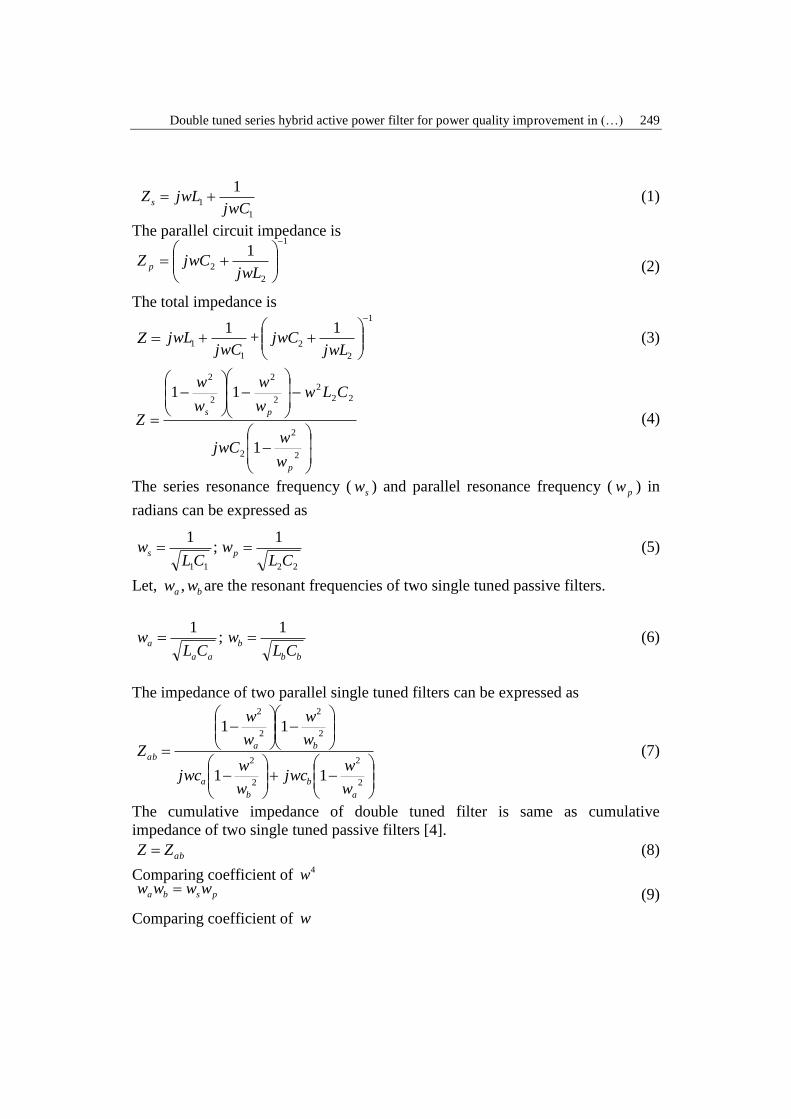
The series circuit impedance is
Double tuned series hybrid active power filter for power quality improvement in (…) 249
1
1
1
jwCjwLZ s (1)
The parallel circuit impedance is 1
2
2
1
jwLjwCZ p (2)
The total impedance is
Z1
1
1
jwCjwL +
1
2
2
1
jwLjwC (3)
2
2
2
22
2
2
2
2
2
1
11
p
ps
w
wjwC
CLww
w
w
w
Z (4)
The series resonance frequency ( sw ) and parallel resonance frequency ( pw ) in
radians can be expressed as
;1
11CLws
22
1
CLwp (5)
Let, ba ww , are the resonant frequencies of two single tuned passive filters.
;1
aa
aCL
w bb
bCL
w1
(6)
The impedance of two parallel single tuned filters can be expressed as
2
2
2
2
2
2
2
2
11
11
a
b
b
a
ba
ab
w
wjwc
w
wjwc
w
w
w
w
Z (7)
The cumulative impedance of double tuned filter is same as cumulative
impedance of two single tuned passive filters [4].
abZZ (8)
Comparing coefficient of 4w psba wwww (9)
Comparing coefficient of w

250 Kumar Reddy Cheepati, Sardar Ali, Surya Kalavathi Munagala
ba CCC 1 (10)
Comparing coefficient of 3w
2122
111
pb
a
a
bw
Cw
Cw
C (11)
The parameter L1 is given by
221
1
bbaa wCwCL
(12)
The series resonance frequency sw and parallel resonance frequency pw of
double tuned filter can be obtained by
11
1
CLws (13)
s
bap
w
www (14)
Since, aw is the zero of double tuned filter impedance, so Z ( aw ) =0. The
equation to solve L2 is
011 12
2
2
2
2
2
CLw
w
w
w
w
p
a
s
a (15)
The above equation can be simplified to get 2L
2
1
2
2
2
2
2
11
a
p
a
s
a
wC
w
w
w
w
L
(16)
The value of 2C can be obtained by
2
2
2
1
pwLC (17)
Hence, all the parameters needed for double tuned filter ),,,( 2211 CLCL can be
calculated from the parameters of two parallel connected single tuned
filters ),,,( bbaa CLCL .
This double tuned passive power filter can provide better performance in
eliminating lower order current harmonics than two single tuned passive filters.
The size of double tuned passive filter is less as compared to single tuned passive
filter and also the reactive power requirement is less [4]. Hence double tuned
passive filter is the best choice for eliminating lower order current harmonics.

Double tuned series hybrid active power filter for power quality improvement in (…) 251
4. Design of series active power filter
The Series active power filter shown in Fig. 4 is as like as the shunt
active power filter, except three isolation transformers and it is able to reduce
harmonics in the source voltages and the voltages applied to the load should be
purely sinusoidal (reducing voltage harmonics) [5]. The series active filter
consists of a voltage-source inverter (input side capacitor and outputside inductor)
and requires three single-phase isolation transformers with suitable kVA rating .
The series active filter is not useful to eliminate current harmonics but it provides
high-impedance to the current harmonics from non-linear load. In this proposed
research, the ultimate aim is to supply the purely sisnusoidal voltages ( cba VVV ,, )
to the different loads connected to the same supply.
Fig. 4. Series active power filter
4.1 Instantaneous power (p-q) theory:
The scientist Akagi et al. in 1983 have derived and proposed the " Theory
of the Instantaneous Reactive Power in a-b-c Circuits", also known as
instantaneous power theory , or p-q theory [5]. The p-q theory works on
instantaneous values in a-b-c power systems without or with neutral wire. It is
useful for both steady-state and transient operations and also it is useful for
improvement of source voltage and current waveforms [5].The p-q theory
involves an algebraic transformation (Clarke transformation) of the voltages and
currents in the a-b-c coordinates to the α - β - 0 coordinates [6] , the calculations
are given by
cs
bs
as
V
V
V
V
V
V
.
2
3
2
30
2
1
2
11
2
1
2
1
2
1
3
20
(18)

252 Kumar Reddy Cheepati, Sardar Ali, Surya Kalavathi Munagala
i
i
i0
2
3
2
30
2
1
2
11
2
1
2
1
2
1
3
2.
c
b
a
i
i
i
(19)
The zero-sequence instantaneous real power is given by:
000 iVp (20)
The instantaneous real power in coordinates is given by
iViVp (21)
The instantaneous imaginary power in coordinates is given by
iViVq (22)
The p and q in the form of coordinates of voltages and currents is given
by
i
i
VV
VV
q
p. (23)
0p average quantity of the instantaneous zero-sequence real power which
corresponds to the energy per unit time which is coming from the source to the
load via the 00 & iV [6].
~
0p changed quantity of the instantaneous zero-sequence real power which
means that the energy per unit time that is exchanged among the source and the
load via the zero-sequence values. The zero-sequence power avaible in three-
phase systems with only neutral wire. In order to have zero sequence components,
the systems must have unbalanced voltages and currents and/or 3rd harmonics in
both voltage and current of at least any of one phase [7]. The power flow
diagram is shown in Fig. 5 indicates the flow of various power quantities such as
p average quantity of the instantaneous real power which corresponds to the
energy per unit time which is coming from the source to the load, via the a-b-c
coordinates, in a balanced way i.e only positive sequence [8].
~
p changed quantity of the instantaneous real power which is the energy per
time unity that is circulating between the source and the load, via the a-b-c
coordinates [9].

Double tuned series hybrid active power filter for power quality improvement in (…) 253
q instantaneous reactive power which belongs to the power that is circulated
between the lines(L-L) of the load [11]. This component does not involves any
circulation or exchange of energy between the source and the load, but it is
indication of the availability of unwanted currents circulate between the phases.
For a balanced sinusoidal voltage supply and a balanced load, with or without
harmonics, q (the mean value of the instantaneous imaginary power) is equal to
the conventional reactive power [10].
Fig. 5. Power flow diagram
The instantaneous theory is one of the best method that can be used in the
control of series active filters. The important features of p-q theory are:
- it is inbuilt a three-phase theory;
-iIt is applicable to any a-b-c system like balanced, unbalanced and with or
without harmonics for source voltage and current waveforms) [11];
- it works on instantaneous powers, gives an excellent stedy state and dynamic
response and also it can be applied to variable non-linear loads [12];
- the calculations are very simple (it only requires algebraic equations that must
be incorporated using standard processors);
- it permits two control strategies: constant instantaneous supply power and
sinusoidal supply current [13].
In this proposed research constant instantaneous supply power theroy was used.
4.2 p-q Theroy applied to series active power filters:
Instantaneous p-q control theory was applied to the voltage series active
power filter to eliminate voltage harmonics in distributed power system under
non-linear conditions. Filter series allows to eliminate voltage harmonics of
supply points where voltage is non-sinusoidal and to supply the user with
sinusoidal voltage. The p-q technique is divided into three stages as shown in Fig.
6. The first stage is the sensing of essential voltage and current signals with
power transformers and current transformers to gather exact power system
information [14]. The second stage involves deriving compensating commands in
terms of current or voltage levels based on filter configuration and control
methods [14]. The third stage of control used to derive the necessary gating
signals for the MOSFET or IGBT of the active filter using hysteresis control
techniques [15]. The instantaneous p-q theory has been used for deriving the
254 Kumar Reddy Cheepati, Sardar Ali, Surya Kalavathi Munagala
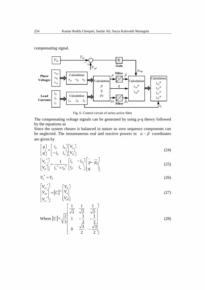
compensating signal.
Fig. 6. Control circuit of series active filter
The compensating voltage signals can be generated by using p-q theory followed
by the equations as
Since the system chosen is balanced in nature so zero sequence components can
be neglected. The instantaneous real and reactive powers in coordinates
are given by
V
V
ii
ii
q
p. (24)
22*
*1
iiV
V
ii
ii
q
pp 0
~
(25)
0
*
0 VV (26)
1
*
*
*
C
V
V
V
cc
cb
ca
V
V
V0
(27)
Where C =
2
3
2
30
2
1
2
11
2
1
2
1
2
1
3
2 (28)

Double tuned series hybrid active power filter for power quality improvement in (…) 255
5. Results and discussion
5.1 Without filter
When the power system is connected to a non-linear load, there is a
generation of harmonics, which disturb the source voltage and current waveforms.
The harmonic disturbance in voltage and current waveform is expressed in terms
of Total Harmonic Distortion (THD). The THD of source voltage and source
current without having any power filter is given in Fig. 8 & 10 and corresponding
waveforms are shown in Fig. 7 & 9.
Fig. 7. Source voltage
Fig. 8. THD of source voltage
Fig. 9. Source current
Fig. 10. THD of source current
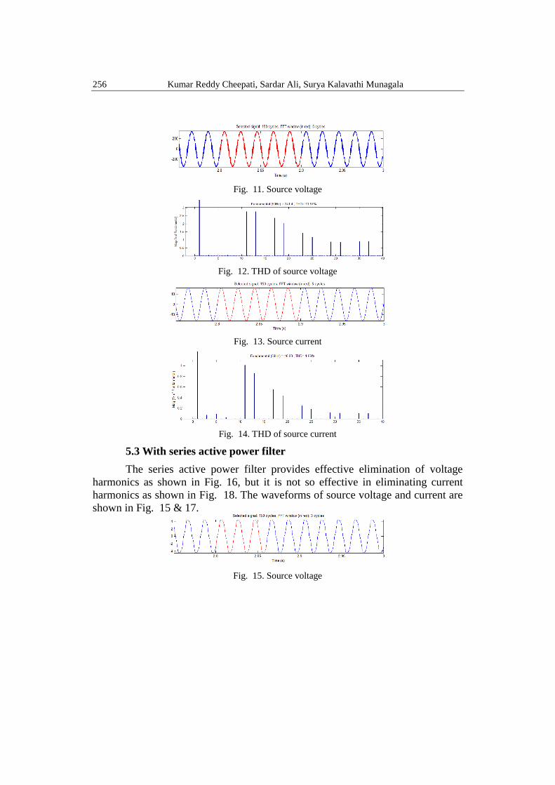
5.2 With double tuned passive filter
The double tuned filter provides effective elimination of lower order
current harmonics than higher order current harmonics and also it eliminates some
voltage harmonics as shown in Fig. 12 & 14 and corresponding waveforms are
shown in Fig. 11 & 13.
256 Kumar Reddy Cheepati, Sardar Ali, Surya Kalavathi Munagala
Fig. 11. Source voltage
Fig. 12. THD of source voltage
Fig. 13. Source current
Fig. 14. THD of source current
5.3 With series active power filter
The series active power filter provides effective elimination of voltage
harmonics as shown in Fig. 16, but it is not so effective in eliminating current
harmonics as shown in Fig. 18. The waveforms of source voltage and current are
shown in Fig. 15 & 17.
Fig. 15. Source voltage

Double tuned series hybrid active power filter for power quality improvement in (…) 257
Fig. 16. THD of source voltage
Fig. 17. Source current
Fig. 18. THD of source current
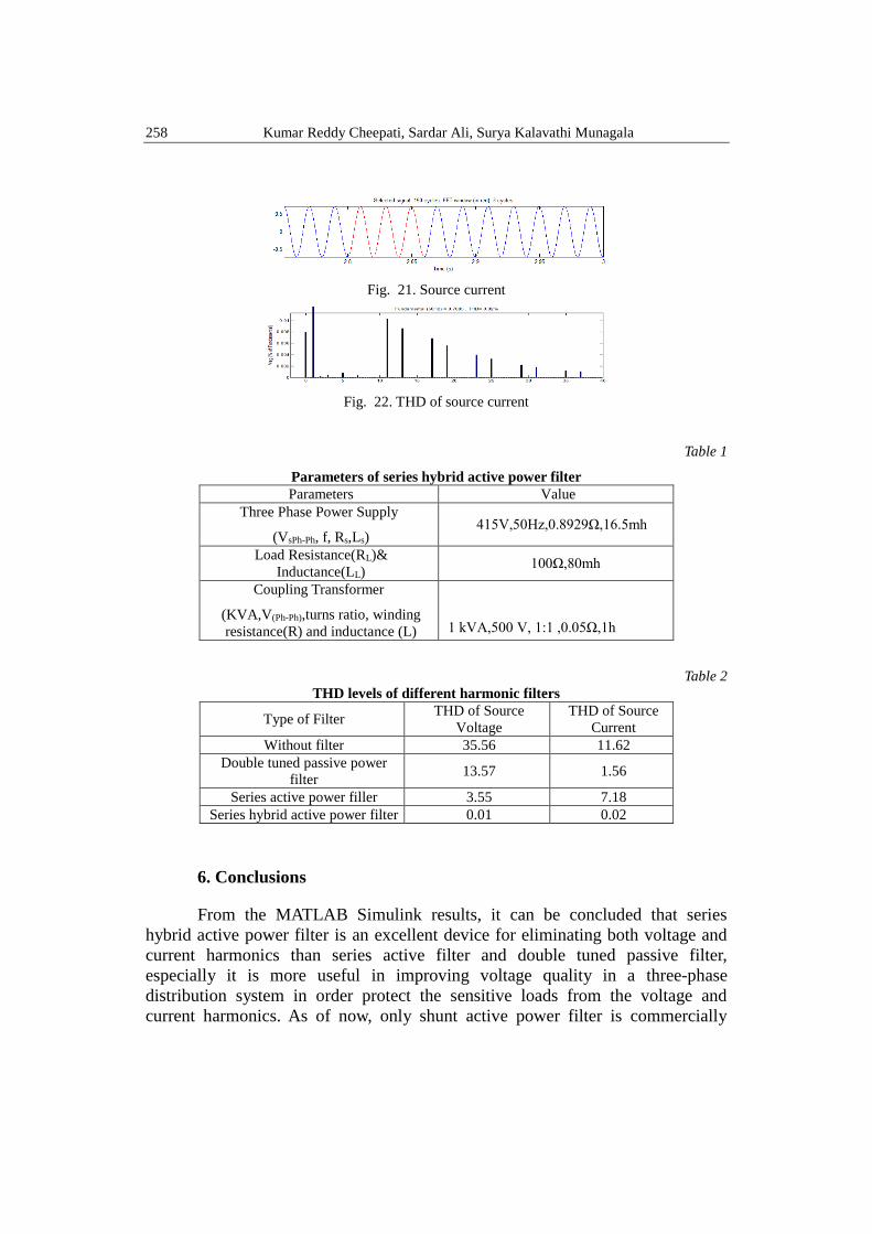
5.4 With series hybrid active power filter
Series hybrid active power filter provides effective elimination of both
voltage and current harmonics as compared to series active and double tuned
passive filter alone as shown in Fig. 20 & 22 and corresponding waveforms are
shown in Fig. 19 & 21.
Fig. 19. Source voltage
Fig. 20. THD of source voltage
258 Kumar Reddy Cheepati, Sardar Ali, Surya Kalavathi Munagala
Fig. 21. Source current
Fig. 22. THD of source current
Table 1
Parameters of series hybrid active power filter Parameters Value
Three Phase Power Supply
(VsPh-Ph, f, Rs,Ls) 415V,50Hz,0.8929Ω,16.5mh
Load Resistance(RL)&
Inductance(LL) 100Ω,80mh
Coupling Transformer
(KVA,V(Ph-Ph),turns ratio, winding
resistance(R) and inductance (L)
1 kVA,500 V, 1:1 ,0.05Ω,1h
Table 2
THD levels of different harmonic filters
Type of Filter THD of Source
Voltage
THD of Source
Current
Without filter 35.56 11.62
Double tuned passive power
filter 13.57 1.56
Series active power filler 3.55 7.18
Series hybrid active power filter 0.01 0.02
6. Conclusions
From the MATLAB Simulink results, it can be concluded that series
hybrid active power filter is an excellent device for eliminating both voltage and
current harmonics than series active filter and double tuned passive filter,
especially it is more useful in improving voltage quality in a three-phase
distribution system in order protect the sensitive loads from the voltage and
current harmonics. As of now, only shunt active power filter is commercially

Double tuned series hybrid active power filter for power quality improvement in (…) 259
available in the market so, there is future research scope on developing hardware
model of a series hybrid active power filter. Instantaneous power theory (p-q) can
be applied to eliminate current and voltage harmonics for balanced, unbalanced
and transient conditions. The performance of series hybrid active power filter for
higher voltage rating can be improved by implementing multi-level inverter with
suitable control strategy.
R E F E R E N C E S
[1] H. Akagi, Y. Kanazawa, A. Nabae, Generalized Theory of the Instantaneous Reactive Power
in Three-Phase Circuits, IPEC'83 - Int. Power Electronics Conf., Tokyo, Japan, , pp. 1375-
1386, 1983.
[2] H. Akagi, Y. Kanazawa, A. Nabae, Instanataneous Reactive Power Compensator
Comprising Switching Devices without Energy Storage Compenents”, IEEE Trans.
Industry Applic., vol. 20, May/June ,1984.
[3] HE Yi-hong, SU Heng “A New Method of Designing Double –tuned Filter” Proceedings of
the 2nd international conference on computer science and electronics engineering ICCSEE,
2013.
[4] Xiao Yao. Algorithm for the Parameters of Double Tuned Filter[J]. USA: IEEE, 1: 154-157,
1998.
[5] H. Akagi, “New trends in active filters for power conditioning”, IEEE Trans. on Ind. Appl.,
Vol. 32, No. 6, pp. 1312-1322, 1996.
[6] João Afonso, Carlos Couto, Júlio Martins” Active Filters with Control Based on the p-q
Theory” IEEE Industrial Electronics Society Newsletter vol. 47, no. 3, Sept., ISSN: 0746-
1240, pp. 5-10, 2000.
[7] Bhim Singh, Kamal Al-Haddad and Ambrish Chandra, "A Review of Active Filters for
Power Quality Improvement" IEEE Trans. Ind. Applicat., vol. 46, NO.5 pp. 960-971,
October, 1999.
[8] Roger C. Dugan, Mark, F. McGranaghan, Surya Santoso and H.Wayne Beaty "Electrical
Power Systems Quality" Tata Mcgrw-hill 3rd edition.
[9] M. El-Habrouk, M.K. Darwish and P. Mehta, “Active power filters: a review”, IEE Proc.
EPA, Vol. 147, No. 5, pp. 403-413, 2000.
[10] S. Rechka, E. Ngandui, J.Xu and P. Sicard, “A comparative study of harmonic detection
algorithms for active filter and hybrid active filers”, IEEE Power Elec. Specialist Conf., pp.
357-363, 2002.
[11] H. Akagi and A. Nabae, “The p-q theory in three-phase systems under non-sinusoidal
conditions”, European Transaction on Electric Power, Vol. 3, pp. 27-31, 1993.
[12] Kumar Reddy Cheepati, Sardar Ali, and M. Surya Kalavathi. "Implementation of Shunt
Hybrid Active Filter (SHAF) For Power Quality Improvement with Fuzzy Logic Controller
to Mitigate Current Harmonics." IJEEE, Vol.7, Issue:02, pp.1-10, 2015.
[13] S Kothuru, J Kothuru, Kumar Reddy.CH “Reduction of Harmonics in 3-Phase, 3-Wire System
by the Use of Shunt active filter” International Conference on Circuit, Power and
Computing Technologies [ICCPCT], 2014.
[14] Kumar Reddy Cheepati and T.Nageswara Prasad “Performance Comparison of Short Term

260 Kumar Reddy Cheepati, Sardar Ali, Surya Kalavathi Munagala
Load Forecasting Techniques” International Journal of Grid and Distributed Computing
Vol. 9, No. 4, pp.287-302, 2016.
[15] Kumar Reddy Cheepati, Sardar Ali, and M. Surya Kalavathi. "Performance Analysis of
Double Tuned Passive Filter for Power Quality." International Journal of Control Theory
and Applications, Vol. 9, Issue:07, pp.3295-3305, 2016.