domain-specific modeling environments by gregory … · domain-specific modeling environments by...
TRANSCRIPT
METAMODELING – RAPID DESIGN AND EVOLUTION OF
DOMAIN-SPECIFIC MODELING ENVIRONMENTS
By
Gregory G. Nordstrom
Dissertation
Submitted to the Faculty of the
Graduate School of Vanderbilt University
in partial fulfillment of the requirements
for the degree of
DOCTOR OF PHILOSOPHY
in
Electrical Engineering
May, 1999
Nashville, Tennessee
Approved: Date:
________________________________________________ ____________________
________________________________________________ ____________________
________________________________________________ ____________________
________________________________________________ ____________________
________________________________________________ ____________________

Copyright by Gregory Gustaf Nordstrom 1999
All Rights Reserved
iii
To Victoria,
A wife of noble character who can find? She is worth far more than rubies.Proverbs 31:10 (NIV)
and
Christopher, Steven, and Michael
Like arrows in the hands of a warrior are sons born in one's youth.Blessed is the man whose quiver is full of them!
Psalm 124:4-5 (NIV)

iv
ACKNOWLEDGEMENTS
An undertaking such as this cannot be completed alone, and I would like to
acknowledge and thank the many persons who helped me in this work. First and foremost
is my wife, Vikki. She has supported me through thick and thin for more years than either
of us likes to admit, and this endeavor was no different. I simply cannot find words to
adequately express my complete and utter awe at her talents, commitment to service, and
capacity for love. I thank God for her every single day.
Special thanks go to the members of my dissertation committee, and especially
the committee chairman, Dr. Janos Sztipanovits. The outstanding mentoring and
leadership provided to me by Dr. Sztipanovits, along with his technical understanding,
insight, encouragement, integrity, and love of discovery and investigation have worked to
build in me the determination, devotion, and confidence to make this research effort a
success. Köszönöm.
I also received large amounts of technical direction, advise, and encouragement
from the members of Vanderbilt's Institute for Software Integrated Systems. My thanks to
each and every member, but especially to Dr. Gabor Karsai, Dr. Akos Ledeczi, and Mr.
Richard "Bubba" Davis for their outstanding contributions to this research. Clearly, none
of this would have been possible without them.
Finally, thanks for the support and sponsorship given by the Defense Advanced
Research Projects Agency, Information Technology Office, Evolutionary Design of
Complex Software program (under Dr. John Salasin), contract #F30602-96-2-0227.
v
TABLE OF CONTENTS
Page
ACKNOWLEDGEMENTS............................................................................................ iv
LIST OF FIGURES......................................................................................................viii
LIST OF TABLES ..........................................................................................................x
LIST OF ABBREVIATIONS.........................................................................................xi
Chapter
I. INTRODUCTION...............................................................................................1
II. BACKGROUND.................................................................................................6
Model Integrated Program Synthesis.................................................................6Metamodeling Concepts ...................................................................................8
Modeling Syntax, Semantics, and Presentation...........................................10Model Composition, Validation, and Translation .......................................14Constraint Management .............................................................................20
Literature Review of Metamodeling Languages ..............................................22Aesop and Armani .....................................................................................23Architecture Meta-Language......................................................................27CASE Data Interchange Format .................................................................30A Denotational Framework for Comparing Models ....................................33EXPRESS..................................................................................................35Model Description Language .....................................................................38Meta Object Facility...................................................................................41Formal Methods.........................................................................................44Unified Modeling Language.......................................................................47Summary of Metamodeling Languages ......................................................50
Preliminary Work ...........................................................................................51OMT/Specware-Based Metamodeling........................................................51A GME/MCL Metamodeling Environment ................................................62Analysis and Lessons Learned....................................................................67
III. UML/GME METAMODELING........................................................................70
vi
Modeling Environment Resources ..................................................................70Model Creation and Visualization ..............................................................71Model Composition....................................................................................73Constraint Management .............................................................................75Persistent Storage.......................................................................................76Semantic Translation..................................................................................77
Syntactic and Semantic Mapping ....................................................................77UML Class Diagrams.................................................................................78GME Object Representation.......................................................................84
Metamodeling Process ....................................................................................88Discussion .................................................................................................... 100
IV. UML/GME METAMODELING ENVIRONMENT ........................................ 101
Metamodel Translation ................................................................................. 104
V. CASE STUDY ................................................................................................ 107
Representational Metamodels ....................................................................... 107ACME ..................................................................................................... 107Meta-Metamodel...................................................................................... 113UML/GME Meta-Metamodel and UML Meta-Metamodel Comparison ... 115
VI. RESULTS AND FUTURE WORK.................................................................. 120
Analysis of the UML/GME Metamodeling Environment .............................. 120Capabilities .............................................................................................. 121Limitations and Restrictions..................................................................... 122
Recommendations for Future UML/GME Metamodeling Research............... 124MCL Expression "Helper"........................................................................ 124Additional MCL Operations..................................................................... 125Additional Constraint Synthesis ............................................................... 125Model/Atomic Part Synthesis ................................................................... 125UML Diagram Partitioning ...................................................................... 126
Appendices
A. MODELING ......................................................................................................... 127
B. FORMAL METHODS .......................................................................................... 138
C. META-INTERPRETER ALGORITHM ................................................................ 143

vii
D. THE UML/GME META-METAMODEL.............................................................. 147
REFERENCES ........................................................................................................... 154
viii
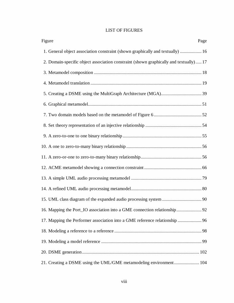
LIST OF FIGURES
Figure Page
1. General object association constraint (shown graphically and textually) .................. 16
2. Domain-specific object association constraint (shown graphically and textually) ..... 17
3. Metamodel composition .......................................................................................... 18
4. Metamodel translation ............................................................................................. 19
5. Creating a DSME using the MultiGraph Architecture (MGA).................................. 39
6. Graphical metamodel............................................................................................... 51
7. Two domain models based on the metamodel of Figure 6 ........................................ 52
8. Set theory representation of an injective relationship ............................................... 54
9. A zero-to-one to one binary relationship .................................................................. 55
10. A one to zero-to-many binary relationship ............................................................... 56
11. A zero-or-one to zero-to-many binary relationship................................................... 56
12. ACME metamodel showing a connection constraint ................................................ 66
13. A simple UML audio processing metamodel ........................................................... 79
14. A refined UML audio processing metamodel........................................................... 80
15. UML class diagram of the expanded audio processing system ................................. 90
16. Mapping the Port_IO association into a GME connection relationship ..................... 92
17. Mapping the Performer association into a GME reference relationship .................... 96
18. Modeling a reference to a reference ......................................................................... 98
19. Modeling a model reference .................................................................................... 99
20. DSME generation .................................................................................................. 102
21. Creating a DSME using the UML/GME metamodeling environment..................... 104
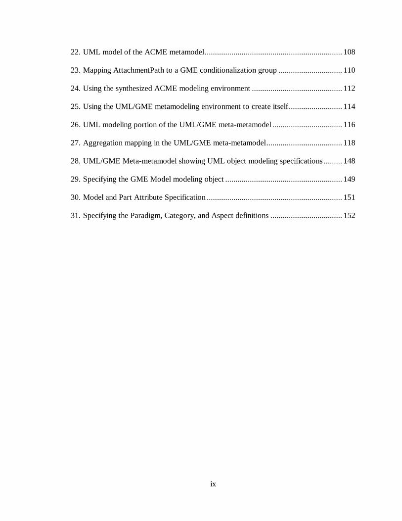
ix
22. UML model of the ACME metamodel................................................................... 108
23. Mapping AttachmentPath to a GME conditionalization group ............................... 110
24. Using the synthesized ACME modeling environment ............................................ 112
25. Using the UML/GME metamodeling environment to create itself .......................... 114
26. UML modeling portion of the UML/GME meta-metamodel .................................. 116
27. Aggregation mapping in the UML/GME meta-metamodel..................................... 118
28. UML/GME Meta-metamodel showing UML object modeling specifications ......... 148
29. Specifying the GME Model modeling object ......................................................... 149
30. Model and Part Attribute Specification .................................................................. 151
31. Specifying the Paradigm, Category, and Aspect definitions ................................... 152
x
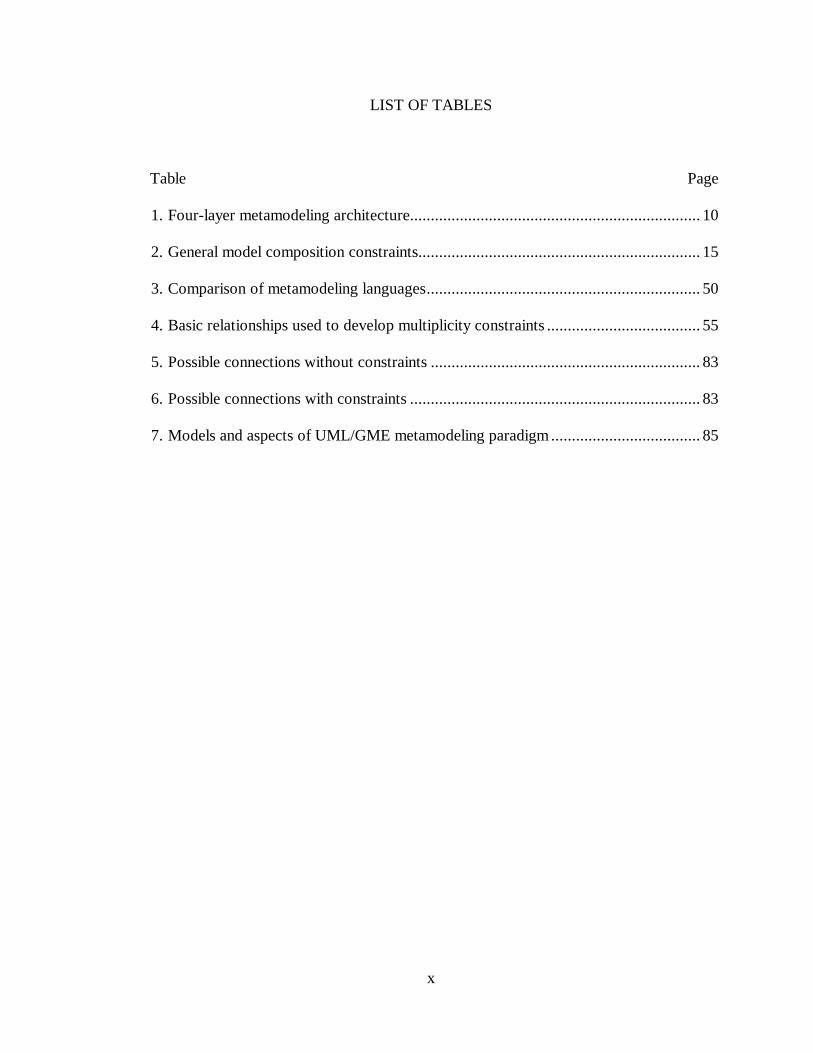
LIST OF TABLES
Table Page
1. Four-layer metamodeling architecture...................................................................... 10
2. General model composition constraints.................................................................... 15
3. Comparison of metamodeling languages.................................................................. 50
4. Basic relationships used to develop multiplicity constraints ..................................... 55
5. Possible connections without constraints ................................................................. 83
6. Possible connections with constraints ...................................................................... 83
7. Models and aspects of UML/GME metamodeling paradigm .................................... 85
xi
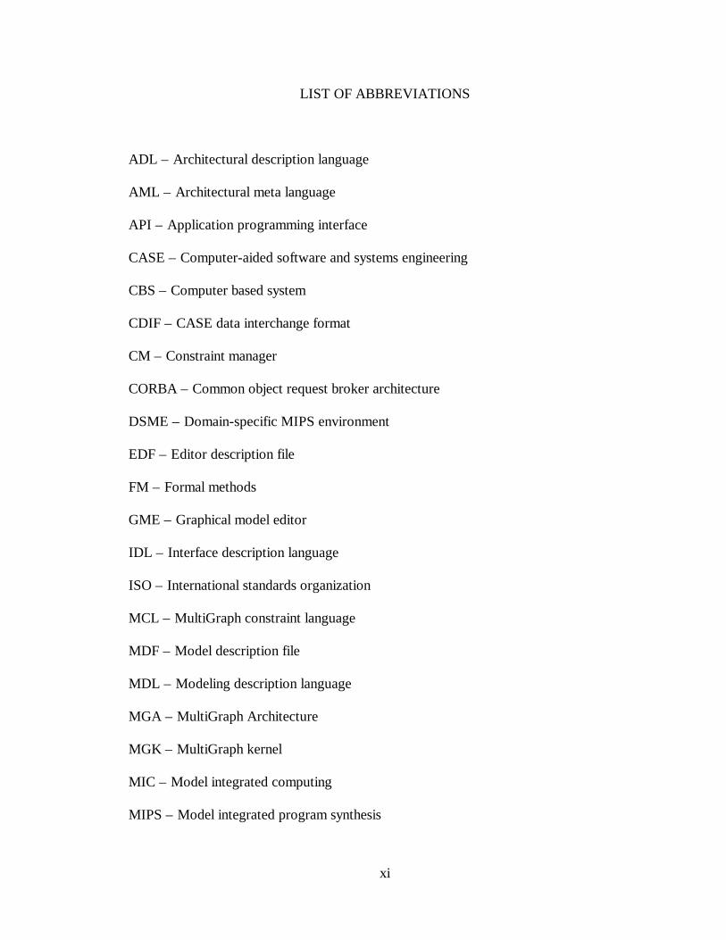
LIST OF ABBREVIATIONS
ADL – Architectural description language
AML – Architectural meta language
API – Application programming interface
CASE – Computer-aided software and systems engineering
CBS – Computer based system
CDIF – CASE data interchange format
CM – Constraint manager
CORBA – Common object request broker architecture
DSME – Domain-specific MIPS environment
EDF – Editor description file
FM – Formal methods
GME – Graphical model editor
IDL – Interface description language
ISO – International standards organization
MCL – MultiGraph constraint language
MDF – Model description file
MDL – Modeling description language
MGA – MultiGraph Architecture
MGK – MultiGraph kernel
MIC – Model integrated computing
MIPS – Model integrated program synthesis
xii
MODL – Meta-object definition language
MOF – Meta object facility
OCL – Object constraint language
OMT – Object modeling technique
POSIX – Portable operating system interface
SDAI – Standard data access interface
STEP – Standard for product data exchange
UML – Unified modeling language
VHDL – VHSIC hardware description language
VHSIC – Very high speed integrated circuit
1
CHAPTER I
INTRODUCTION
Large computer-based systems (CBSs), where functional, performance, and
reliability requirements demand the tight integration of physical processes and
information processing, are among the most significant technological developments of
the past 20 years [1]. CBSs operate in ever-changing environments, and throughout a
CBS system’s life cycle, changes in mission requirements, personnel, hardware, support
systems, etc., all drive changes to the CBS. Rapid reconfiguration via software has long
been seen as a potential means to effect rapid change in such systems. Examples of such
environments include process control and monitoring; real-time diagnostics and analysis;
information distribution and management; surety of high consequence, high assurance
systems; and fault detection, isolation, and recovery.
Due to the extremely complex nature of large-scale, mission-critical systems,
software modification involves a large amount of risk. The magnitude of this risk is
proportional to the size of the system, not to the size of the change. Small modifications
in one area can cause large and unforeseen changes in others. Because such risk is always
present, it must be managed. To effectively manage such risk, the entire system must be
designed to evolve. Key factors in this evolution are:
• Requirements capture: A method to state the system’s requirements and design in
concise and unambiguous terms.
2
• Program synthesis: The ability to automatically transform requirements and design
information into application software.
• Application evolution: A method to safely and efficiently evolve the software over
time as application requirements change.
• Design environment evolution: A method to ensure the design environment can
correctly model domain-specific systems as domain requirements change.
An emerging technology that enables such evolution is model integrated computing
(MIC). MIC allows designers to create models of domain-specific systems, validate these
models, and perform various computational transformations on the models.
One approach to MIC is model-integrated program synthesis (MIPS). In MIPS,
models are created that capture various aspects of a domain-specific system's desired
behavior. Model interpreters are used to translate these models for use in the system's
execution environment, either as stand-alone applications or in conjunction with code
libraries and some form of middleware (e.g. CORBA, the MultiGraph kernel (MGK),
POSIX, etc.) When changes in the overall system require new application programs, the
models are updated to reflect these changes, and the applications are regenerated
automatically from the models.
The MultiGraph Architecture (MGA), under development at Vanderbilt University,
is a toolset for creating domain-specific MIPS environments. Although the MGA
provides a means for quickly and accurately evolving domain-specific applications, such
capability is generally not enough to keep pace with large changes in systems
requirements. Throughout the lifetime of a system, particularly a large-scale system,
requirements often change in ways that force the entire design environment to change.
3
For example, if a domain-specific MIPS environment (DSME) exists for modeling a
chemical plant and generating executable code for use on the plant's monitoring and
analysis computers, what happens when new equipment is later added to the plant –
equipment that was not in use or was unheard of at the time the DSME was created? In
all likelihood, the existing DSME would not be able to model new configurations of the
plant. In a case such as this, the entire DSME would have to be rebuilt so that new
equipment could be incorporated into existing and future plant models.
Clearly, these DSMEs must be updated as changes in the domain arise. Currently,
DSMEs are handcrafted, and rebuilding a DSME can be a long and costly process. What
is needed is a way to automatically generate the DSME. One approach is to model the
DSME itself – to "model the modeling environment" in a manner similar to modeling a
particular domain-specific application. (In fact, a DSME is a domain-specific application,
where the domain is the set of all possible MIPS environments). Just as domain-specific
models are used to generate domain-specific applications, by adding a metaprogramming
interface to a MIPS environment, the MIPS environment can be used to generate various
DSMEs. Such a MIPS environment is called a metamodeling environment. Because
models created using a metamodeling environment describe other modeling systems, they
are called metamodels. Metamodels are formalized descriptions of the objects,
relationships, and behavior required in a particular DSME. It can be seen that this
approach to DSME design and evolution is similar to that of evolving domain-specific
applications using DSMEs – just "up one level" in the design hierarchy.
4
The MGA has been in use for almost 10 years, and has provided the tools necessary
to create a wide variety of DSMEs. Currently, however, the MGA supports only a
rudimentary metaprogrammable interface. Therefore, my thesis is:
It is possible to specify, synthesize, and evolve domain-specific modeling
environments by designing and incorporating a complete meta-programming layer
into the MGA, thereby reducing the risk of large-scale computer-based system
development.
This dissertation presents the concepts behind, and a methodology for, creating
such a metaprogramming layer and incorporating it into the MGA. The background
section discusses metamodeling concepts and challenges, develops a taxonomy of
metamodeling language criteria, and presents the results of a metamodeling languages
literature review, including an analysis of each language based on the previously
developed criteria. The background section concludes by presenting preliminary
metamodeling research performed in preparation for this dissertation.
Next the various modeling environment resources are discussed, such as the
facilities for creating, visualizing, and composing metamodels. Constraint management
and persistent storage are also discussed, and a general strategy is developed for mapping
UML-based metamodeling specifications to the MultiGraph graphical modeling
environment. The complete metamodeling process is presented, and the prototype
UML/GME metamodeling environment is presented and discussed.
Following this discussion, a case study is conducted to demonstrate how the
metamodeling tool is used to specify and synthesize various domain-specific modeling

5
environments. The results of the case study are analyzed to determine the capabilities and
usability of the metamodeling environment, as well as to identify any limitations and
restrictions imposed on the metamodeler by the system. Finally, recommendations for
future enhancements to the UML/GME metamodeling system are presented.
6
CHAPTER II
BACKGROUND
This section provides the proper context for the UML/GME metamodeling
discussion that follows in Chapter III. A more detailed review and discussion of
modeling, model-integrated computing, and model-integrated program synthesis is
provided in Appendix A.
Model Integrated Program Synthesis
Modeling is the process of creating an abstract representation of a system, and as
such, becomes a key strategy in the system design process. The artifacts of the modeling
process are models – abstractions of the original system. The most important feature of a
model is its ability to reduce the complexity of a design. To aid designers in creating
models of hardware and software systems, various modeling languages and systems have
been created. For such modeling systems to be successful, they must be specific enough
to enable designers to represent the key elements of various designs, without unduly
constraining the designer, while remaining general enough to allow a fairly wide variety
of models to be created.
Modeling languages exist for many domains, serving many purposes. Some
modeling languages are more suited to the task of hardware and software modeling that
others. This dissertation concentrates on languages designed to model CBSs. The
functional, performance, and reliability requirements of CBSs demand tight integration of
physical systems with information systems [2]. When modeling such systems, it is
7
important that these requirements be captured in a unified set of models. Only with a
unified model set can each aspect of the system's overall behavior (i.e. the functional,
performance, and reliability aspects) be examined as a "separate but integrated" part of
the overall CBS. As discussed in Appendix A, there are several criteria for choosing a
CBS modeling language. These include:
• the ability to model general engineering entities and relationships,
• acceptance of the language as a standard,
• support for a variety of modeling techniques (e.g. state-charts, petri-nets, etc.)
• model composition and reuse capability,
• modeling language extensibility,
• support for an automated design environment,
• the ability to conduct formal analysis and simulation of models,
• the ability to assign semantic meaning to models,
• transformation of structural and behavioral models into executable models, and
• metalanguage support.
Of particular importance is support for a metalanguage – the basis of
metamodeling.
Model-integrated computing (MIC) is a methodology for synthesizing
applications from domain-specific models. MIC allows designers to create multi-aspect
models of domain-specific systems, validate these models, and perform various
computational transformations on the models. One approach to MIC is model-integrated
program synthesis (MIPS).
8
MIPS is a method that allows experts in a particular domain to create integrated
sets of multi-aspect models representing all or part of various domain-specific systems.
These models can then be transformed for use in the system's execution environment,
either as stand-alone applications, or in conjunction with code libraries and some form of
middleware (e.g. CORBA, the MultiGraph kernel (MGK), POSIX, etc.) As application
requirements change over time, the models are updated and new applications are
synthesized, thus allowing for safe and efficient application evolution.
A MIPS environment operates according to a modeling paradigm – a set of
requirements that governs how any system in a particular domain is to be modeled. These
modeling requirements specify the types of entities and relationships that can be
modeled; how best to model them; entity and/or relationship attributes; the number and
types of views or aspects necessary to logically and efficiently partition the design space;
how semantic information to is to be captured by, and later extracted from, the models;
any analysis requirements; and, in the case of executable models, run-time requirements.
Once a modeling paradigm has been established, the MIPS environment itself can
be built. A MIPS environment consists of three main components: (1) a domain-aware
model builder used to create and modify models of domain-specific systems, (2) the
models themselves, and (3) one or more model interpreters used to extract and translate
semantic knowledge from the models. See Appendix A for a detailed description of each
of these components.
Metamodeling Concepts
More and more, the prefix meta is being attached to words that describe various
modeling and data representation activities. For example, a literature search on the
9
keyword "metamodel" will yield many references to "meta" methods and terms such as
metamodeling, metadata, metarelation, metaassociation, metaattribute, metaclass,
metaobject, metaCASE, etc. Unfortunately, the term “meta” is not applied consistently,
causing considerable confusion among researchers. Therefore, in the context of this
dissertation, the following definitions apply:
• Model: An abstract representation of a CBS.
• Modeling Environment: A system, based on a modeling paradigm, for creating,
analyzing, and translating domain-specific models.
• Metamodel: A model that formally defines the syntax and semantics of a particular
domain-specific modeling environment.
• Metamodeling Environment: A tool-based framework for creating, validating, and
translating metamodels.
• Meta-metamodel: A model that formally defines the syntax and semantics of a given
metamodeling environment.
To better compare and contrast metamodeling approaches and methodologies, a
taxonomy of metamodeling language characteristics is necessary. Such a taxonomy is
best developed by examining fundamental metamodeling concepts.
In a very real sense, modeling and metamodeling are identical activities – the
difference being one of interpretation. Models are abstract representations of real-world
systems or processes. When the process being modeled is the process of creating other
models, the modeling activity is correctly termed metamodeling. Therefore, concepts that
apply to modeling also apply to metamodeling. This logic can be extended to the process
10
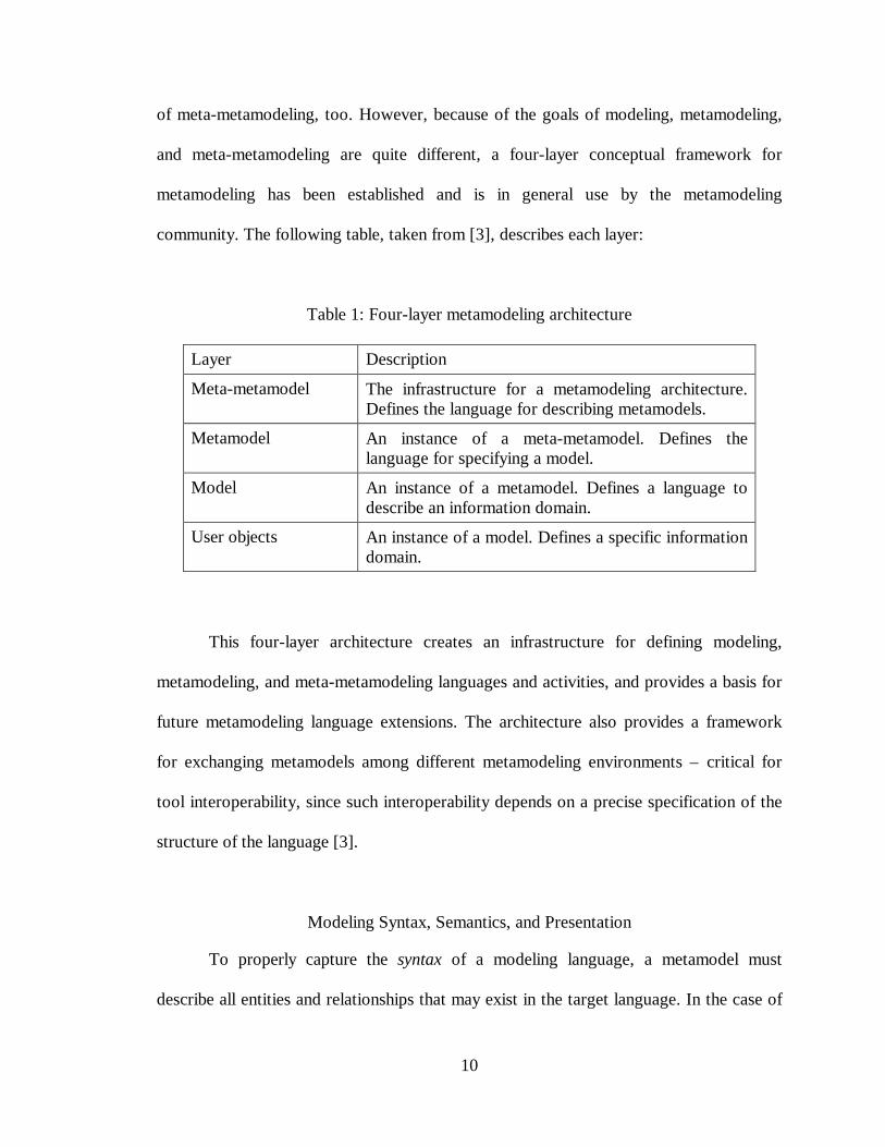
of meta-metamodeling, too. However, because of the goals of modeling, metamodeling,
and meta-metamodeling are quite different, a four-layer conceptual framework for
metamodeling has been established and is in general use by the metamodeling
community. The following table, taken from [3], describes each layer:
Table 1: Four-layer metamodeling architecture
Layer Description
Meta-metamodel The infrastructure for a metamodeling architecture.Defines the language for describing metamodels.
Metamodel An instance of a meta-metamodel. Defines thelanguage for specifying a model.
Model An instance of a metamodel. Defines a language todescribe an information domain.
User objects An instance of a model. Defines a specific informationdomain.
This four-layer architecture creates an infrastructure for defining modeling,
metamodeling, and meta-metamodeling languages and activities, and provides a basis for
future metamodeling language extensions. The architecture also provides a framework
for exchanging metamodels among different metamodeling environments – critical for
tool interoperability, since such interoperability depends on a precise specification of the
structure of the language [3].
Modeling Syntax, Semantics, and Presentation
To properly capture the syntax of a modeling language, a metamodel must
describe all entities and relationships that may exist in the target language. In the case of
11
a multi-aspect modeling language, the metamodel must clearly define a partitioning of
these entities and relationships across all aspects of the modeling language. This is
especially important in the case of graphical modeling languages. As discussed in [3],
when specifying graphical modeling languages, an abstract syntax – a language syntax
devoid of implementation details – is first specified. Then a concrete syntax is defined as
a mapping of the graphical notation onto the abstract syntax. In a graphical metamodel,
the syntax is modeled as a collection of modeling object types, along with the
relationships allowed between those object types and any attributes associated with the
objects.
In addition to specifying the syntax of modeling language, semantics must also be
specified in a metamodel. For example, consider a DSME for embedded processor
modeling. A metamodel describing such an environment would likely include processor
and sensor entities, and a connectedTo relationship specifying how sensors are related to
processors. Furthermore, the number of individual processors and sensors that participate
in the connectedTo relationship must also be specified, so the metamodel would need a
multiplicity specification for the connectedTo relationship. Depending on the particular
types of processors and sensors, such a metamodel might specify that one sensor can be
connected to at most three processors, or that one processor can be connected to no more
than five sensors.
It is necessary to distinguish among two types of semantics – static and dynamic.
Static semantics refer to the well-formedness of constructs in the modeled language, and
are specified as invariant conditions that must hold for any model created using the
modeling language. Dynamic semantics, however, refer to the interpretation of a given
12
set of modeling constructs in the context of the model instances themselves. Only the
static semantics may be specified in a metamodel, since the metamodel has no way of
knowing a priori what meaning to associate with particular instances (i.e. particular
models) created using the language. Distinguishing between static and dynamic
semantics is best illustrated by an example.
Consider a MIPS environment used to model the behavior of real-time scheduling
systems. A metamodel description of such a MIPS environment would necessarily define
objects and relationships such as tasks, events, and schedules. The static semantics
expressed in the metamodel would include constraints that must be maintained to ensure
a given model is valid. Scheduler models that violate any of these constraints are, by
definition, invalid models. Some possible constraints, stated using standard English,
might be:
• "Task duration must be specified"
• "Schedules can hold a maximum of 10 tasks"
Such constraints represent the static semantics of the modeling language, and can
be defined in the metamodel. However, the following constraints represent dynamic
semantics, and as such, cannot be represented as metamodel constraints:
• "All tasks must meet their execution deadlines"
• "Scheduling queues must never overflow"
The metamodel can define what it means for a task to have a duration associated
with it, and can specify that such "meaning" must be satisfied in any model that includes
13
tasks. If the modeler fails to provide a value for task duration, the model is considered
invalid. However, the metamodel cannot specify the enforcement of a specification
concerning task schedulability, since schedulability is a function of, among other things,
certain run-time factors – factors that the metamodel has no a priori knowledge of.
Another consideration in any metamodeling language is the form of these
invariant constraint statements. Constraints must be stated in such a way as to be precise
and analyzable, so that before any modeling language or modeling environment is
synthesized from a metamodel, it can be shown (i.e. proved) that the metamodel itself
does, in fact, properly specify a set of constraints (constraints that properly define the
static semantics of the modeling language in question). Therefore, the static semantics
should be specified in a mathematical language. An ideal candidate is any first- or higher-
order predicate calculus, since the invariants can take the form of Boolean expressions
that must be satisfied by any model created using the target modeling language. Such
expressions can be tested using a proof checker before the metamodel is used to generate
a modeling language.
In a metamodel, it is important to separate form from function when describing the
target modeling language. Language implementation details (i.e. the "form"), while
necessary to implement the target MIPS environment, need not, and arguably should not,
be included in a metamodel. Implementation details do not add meaning to the simple
and precise syntactic and semantic modeling language specifications (the "function"), and
will, oftentimes, obscure the specification and make metamodel interpretation more
difficult.
14
As stated earlier, making modeling (and metamodeling) tools interoperable
requires that metamodels be exchanged among various metamodeling tool suites. This
requires that the structure of any language – its syntax and semantics – be precisely
specified by the metamodel, even if other aspects, such as implementation details, are
not. Therefore, the metamodeling environment must be able to accept metamodels
specified in a variety of metalanguages, or those metalanguages must be translatable to a
metalanguage that the metamodeling environment understands. This again underscores
the need to separate the implementation details from the language specification itself.
Model Composition, Validation, and Translation
The field of engineering contains many domains, such as process control, digital
signal processing, and information management. While each domain deals with
inherently different notions, certain modeling concepts can be applied to many, if not all,
engineering domains. For example, hierarchy is used in many engineering disciplines to
represent concepts such as information hiding, abstraction, and object inheritance.
Another example is the concept of module interconnection [4], where clearly
defined interfaces are specified between modules, and modules connect to one another
across these interfaces. Modules may contain one or more ports (i.e. specific connection
points) used when making connections to other modules. There are specific rules
governing the use of these ports, such as:
• Input ports can connect to output ports
• Output ports can connect to input ports
• Output ports can not connect to other output ports
15
These module interconnection rules represent constraints that apply whenever
module interconnection is used as a means of modeling component interaction. They
apply whenever module interconnection is used, regardless of which particular
engineering domain the system being modeled belongs to.
The goal is to represent such modeling concepts abstractly as generalized model
composition constraints, and place these representations in a repository or library. The
metamodeler can then access these library objects and compose a metamodel by
combining the constraints in ways dictated by the modeling paradigm. Such an approach
allows quick and accurate construction of metamodels – assuming, of course, that each
constraint has been validated a priori, and that the act of combining or composing
constraints does not negate the individual validations (or that re-validation of the
composed specification can be easily accomplished).
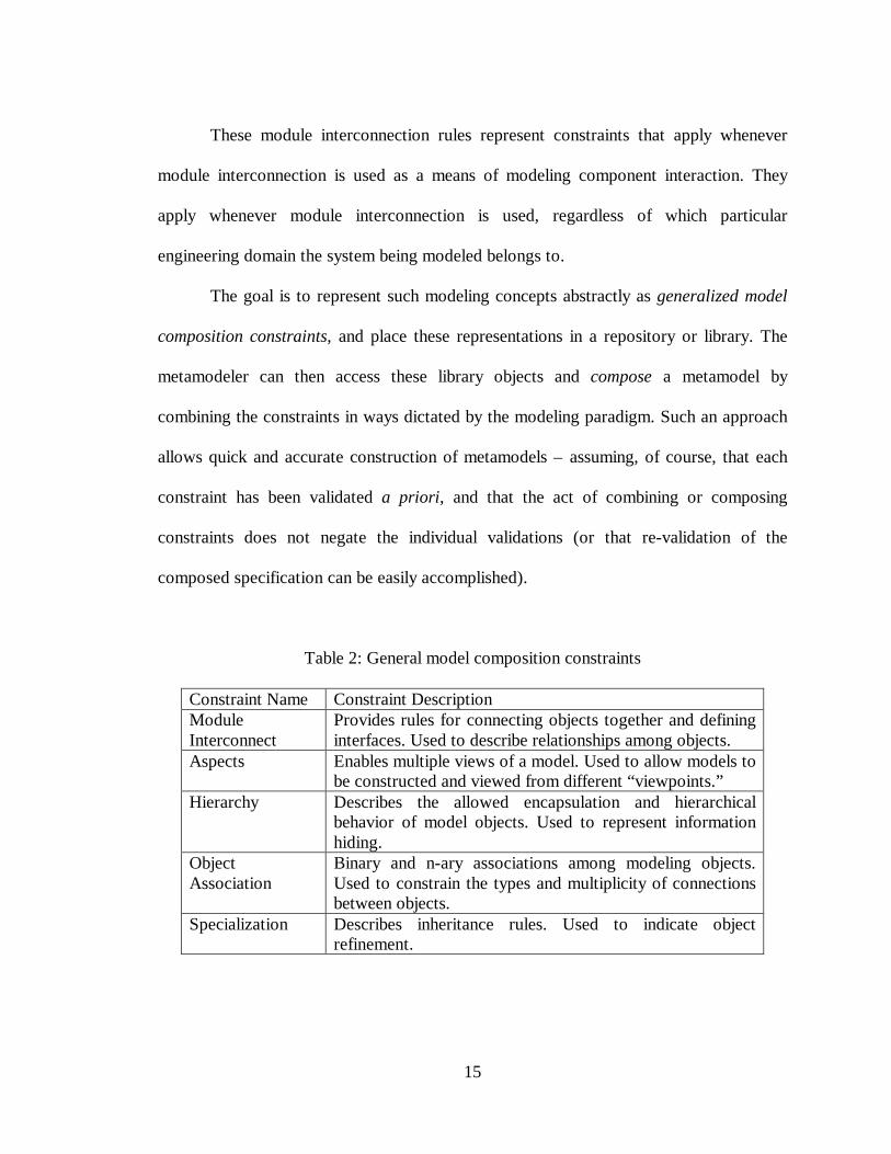
Table 2: General model composition constraints
Constraint Name Constraint DescriptionModuleInterconnect
Provides rules for connecting objects together and defininginterfaces. Used to describe relationships among objects.
Aspects Enables multiple views of a model. Used to allow models tobe constructed and viewed from different “viewpoints.”
Hierarchy Describes the allowed encapsulation and hierarchicalbehavior of model objects. Used to represent informationhiding.
ObjectAssociation
Binary and n-ary associations among modeling objects.Used to constrain the types and multiplicity of connectionsbetween objects.
Specialization Describes inheritance rules. Used to indicate objectrefinement.
16
Table 2 describes several general model composition constraints. Not all domains
need every constraint available in the library. For example, a simple process control
modeling language may not require hierarchical behavior. For this reason, when creating
domain-specific modeling languages, concepts specific to the domain must be known a
priori and must be used to guide the selection of constraints from the library.
Because of the general nature of the constraints listed in Table 2, they are
“family-specific” (e.g. engineering-specific) but not domain-specific. Before they can be
used in a domain-specific metamodel, they must be tailored for the domain. One
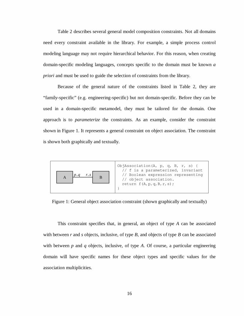
approach is to parameterize the constraints. As an example, consider the constraint
shown in Figure 1. It represents a general constraint on object association. The constraint
is shown both graphically and textually.
A Bp..q r..s
ObjAssociation(A, p, q, B, r, s) { // f is a parameterized, invariant // Boolean expression representing // object association. return f(A,p,q,B,r,s);}
Figure 1: General object association constraint (shown graphically and textually)
This constraint specifies that, in general, an object of type A can be associated
with between r and s objects, inclusive, of type B, and objects of type B can be associated
with between p and q objects, inclusive, of type A. Of course, a particular engineering
domain will have specific names for these object types and specific values for the
association multiplicities.
17
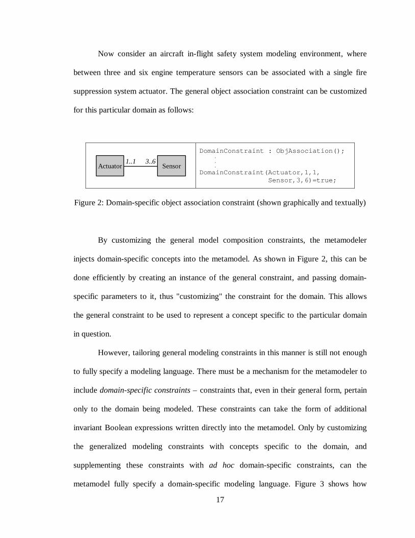
Now consider an aircraft in-flight safety system modeling environment, where
between three and six engine temperature sensors can be associated with a single fire
suppression system actuator. The general object association constraint can be customized
for this particular domain as follows:
Actuator Sensor1..1 3..6
DomainConstraint : ObjAssociation(); . . .
DomainConstraint(Actuator,1,1, Sensor,3,6)=true;
Figure 2: Domain-specific object association constraint (shown graphically and textually)
By customizing the general model composition constraints, the metamodeler
injects domain-specific concepts into the metamodel. As shown in Figure 2, this can be
done efficiently by creating an instance of the general constraint, and passing domain-
specific parameters to it, thus "customizing" the constraint for the domain. This allows
the general constraint to be used to represent a concept specific to the particular domain
in question.
However, tailoring general modeling constraints in this manner is still not enough
to fully specify a modeling language. There must be a mechanism for the metamodeler to
include domain-specific constraints – constraints that, even in their general form, pertain
only to the domain being modeled. These constraints can take the form of additional
invariant Boolean expressions written directly into the metamodel. Only by customizing
the generalized modeling constraints with concepts specific to the domain, and
supplementing these constraints with ad hoc domain-specific constraints, can the
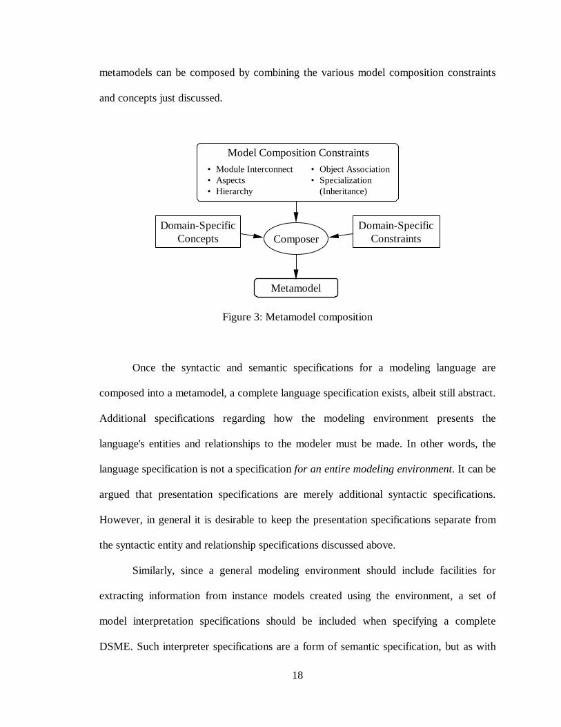
metamodel fully specify a domain-specific modeling language. Figure 3 shows how
18
metamodels can be composed by combining the various model composition constraints
and concepts just discussed.
ComposerDomain-Specific
ConstraintsDomain-Specific
Concepts
Metamodel
• Module Interconnect• Aspects• Hierarchy
• Object Association• Specialization
(Inheritance)
Model Composition Constraints
Figure 3: Metamodel composition
Once the syntactic and semantic specifications for a modeling language are
composed into a metamodel, a complete language specification exists, albeit still abstract.
Additional specifications regarding how the modeling environment presents the
language's entities and relationships to the modeler must be made. In other words, the
language specification is not a specification for an entire modeling environment. It can be
argued that presentation specifications are merely additional syntactic specifications.
However, in general it is desirable to keep the presentation specifications separate from
the syntactic entity and relationship specifications discussed above.
Similarly, since a general modeling environment should include facilities for
extracting information from instance models created using the environment, a set of
model interpretation specifications should be included when specifying a complete
DSME. Such interpreter specifications are a form of semantic specification, but as with
19
the presentation specifications, it is better to develop and maintain interpreter
specifications separately from the semantic specifications already discussed.
In summary, four types of specifications – syntactic, presentation, semantic, and
interpretation – must exist in a metamodel, and are necessary and sufficient to completely
specify a domain specific modeling environment. For the remainder of this dissertation,
the term metamodel will refer to this "complete" definition of a metamodel.
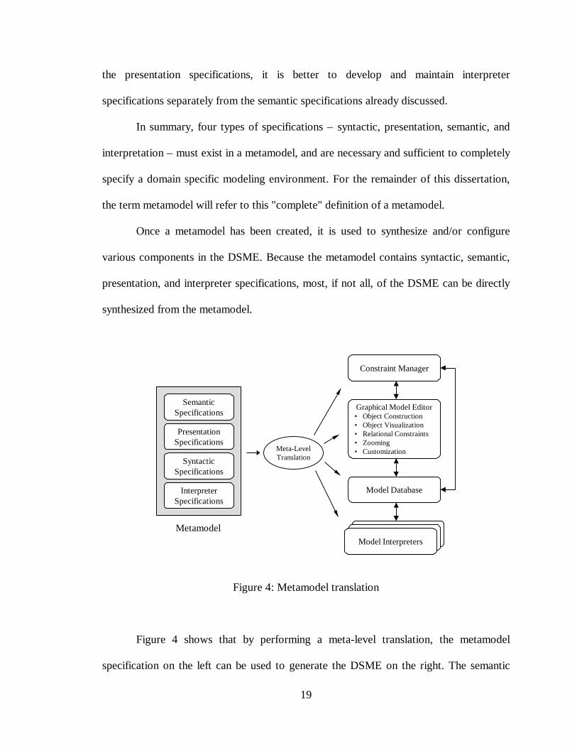
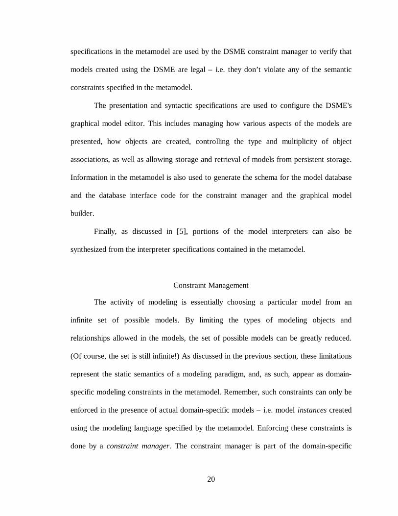
Once a metamodel has been created, it is used to synthesize and/or configure
various components in the DSME. Because the metamodel contains syntactic, semantic,
presentation, and interpreter specifications, most, if not all, of the DSME can be directly
synthesized from the metamodel.
SemanticSpecifications
SyntacticSpecifications
InterpreterSpecifications
Constraint Manager
Graphical Model Editor• Object Construction• Object Visualization• Relational Constraints• Zooming• Customization
Model Database
Model Interpreters
PresentationSpecifications
Metamodel
Meta-LevelTranslation
Figure 4: Metamodel translation
Figure 4 shows that by performing a meta-level translation, the metamodel
specification on the left can be used to generate the DSME on the right. The semantic
20
specifications in the metamodel are used by the DSME constraint manager to verify that
models created using the DSME are legal – i.e. they don’t violate any of the semantic
constraints specified in the metamodel.
The presentation and syntactic specifications are used to configure the DSME's
graphical model editor. This includes managing how various aspects of the models are
presented, how objects are created, controlling the type and multiplicity of object
associations, as well as allowing storage and retrieval of models from persistent storage.
Information in the metamodel is also used to generate the schema for the model database
and the database interface code for the constraint manager and the graphical model
builder.
Finally, as discussed in [5], portions of the model interpreters can also be
synthesized from the interpreter specifications contained in the metamodel.
Constraint Management
The activity of modeling is essentially choosing a particular model from an
infinite set of possible models. By limiting the types of modeling objects and
relationships allowed in the models, the set of possible models can be greatly reduced.
(Of course, the set is still infinite!) As discussed in the previous section, these limitations
represent the static semantics of a modeling paradigm, and, as such, appear as domain-
specific modeling constraints in the metamodel. Remember, such constraints can only be
enforced in the presence of actual domain-specific models – i.e. model instances created
using the modeling language specified by the metamodel. Enforcing these constraints is
done by a constraint manager. The constraint manager is part of the domain-specific
21
modeling environment. It provides various queues to the modeler according to the static
semantics described in the metamodel.
As an example of constraint management, consider an audio signal processing
modeling paradigm. The metamodel specifies the following types of objects:
microphones, preamps, power amps, and loudspeakers. Microphones contain one output
port, preamps and power amps each contain a single input and output port, and a
loudspeaker contains a single input port. The metamodel also specifies the following
relationships among the types: a microphone’s output port may be connected to the input
ports of any number of preamps, a preamp output port may connect to any number of
power amp input ports, and a power amp output port may connect to one or more
loudspeaker input ports. Such syntactic model construction rules can be easily enforced
in the graphical model editor – the graphical editor simply won’t allow any objects or
relationships not specified in the metamodel to exist. However, suppose a domain-
specific constraint is included in the metamodel stating that the output of every power
amp must be connected to something (a very important real-world consideration).
Although such a constraint can easily be stated in the metamodel (for example, by
including an invariant expression stating that the size of the set of objects connected to
the output of any power amp be greater than zero), such a constraint can only be checked
once a specific model exists. In other words, the graphical model editor can prevent
certain editing actions, but cannot guarantee certain editing actions. Of course, the
constraint manager can't guarantee certain editing actions either, but it can indicate that,
at a given point in time, a certain model does not satisfy a particular constraint.
22
As explained above, the constraint manager operates on model instances. Such a
"constraint enforcement mechanism" should not be confused with the formal metamodel
validation that is performed before any domain-specific modeling environment is
synthesized from the metamodel. Metamodel validation is used to ensure that any
modeling environment created from the metamodel specifications will generate valid
models in the domain (i.e. that the modeling language specification is consistent). For
reasons of speed, accuracy, and completeness, the metamodeling language should allow
for machine-aided validation of metamodels. This is only possible when the metamodel
specifications are expressed using a formal language. One possibility would be a
metamodeling language based on Boolean predicate calculus. In the case of graphical
modeling languages, such a calculus can take the form of a supplementary set of
constraint expressions written in an appropriate Boolean expression language. In this
case, care must be taken to ensure the names of object types and relationships appear
correctly in the Boolean expressions. This can be handled as an implementation detail.
Literature Review of Metamodeling Languages
As mentioned in the introduction, the MGA has only a rudimentary
metaprogramming interface, inadequate for several reasons. First, a declarative language
is used for defining modeling paradigms. This simple metalanguage does not support a
rigorous and concise specification of complex modeling semantics. Second, the language
does not support machine-aided validation of the modeling environment definition.
Finally, there is no support for the formal specification of model interpreter semantics or
the semantics of any execution environments, making any verification and validation of
interpreters and execution environments difficult at best [5]. Since the goal is to use the
23
MGA as a metamodeling environment, a new, more complete metamodeling language
must be implemented in the MGA.
What follows is a discussion of several currently available metamodeling
languages and/or metamodeling environments. These will be explained and compared
using the criteria developed in the previous Metamodeling Concepts section. Those
criteria are summarized below:
• Support for the four-layer metamodeling architecture.
• Ability to model both the abstract syntax and static semantics of a modeling language.
• Ability to separate modeling language syntax and semantic specifications (the
"function") from implementation details (the "form").
• Ability to compose metamodels from pre-specified, generalized modeling constraints,
supplemented with necessary domain-specific concepts and constraints.
• Ability to specify static semantics as a set of provably correct invariant expressions
(i.e. constraint expressions).
• Ability to validate the consistency of metamodel using machine-aided methods such
as theorem provers or proof checkers.
• Support for metamodeling tool interoperability by allowing metamodels to be
translated to and from other metamodeling languages.
Aesop and Armani
Carnegie Mellon's Architecture Based Languages and Environments project
group explores the formal basis for Software Architecture and builds tools for practicing
software architects. One such tool, Aesop [6], is a toolkit for producing customized
24
Software Architecture design and analysis environments. While there is no well-accepted
definition for Software Architecture, it is generally recognized that a system's
architectural design (i.e. its Software Architecture) is concerned with describing its gross
decomposition into computational elements and the interactions among those elements
[7][8]. This represents a rather high level of design abstraction, one that is removed from
the details of algorithm design. Such an approach concerns itself with component
composition, control structures, system evolution, and the ability to choose from among
design alternatives. Because software engineers tend to reuse established architectural
organization principles (e.g. client-server, producer-consumer, pipe-and-filter, etc.), they
tend to apply certain reference models and patterns of solution to particular categories of
problems. A set of generalized, category-specific solutions is referred to as an
architectural style.
Aesop allows designers to define architectural styles and apply them when
modeling various software architectures. Each style-specific architectural development
environment created by Aesop supports:
• selection of design element types (i.e. style-specific components and connectors)
as specified by the style,
• design checking to ensure compliance with the particular style's topological
constraints,
• an optional statement of element semantics (using a text-based language of the
modeler's choice),
• an interface that gives external tools access to the architectural descriptions (for
manipulation and analysis of the descriptions),
25
• various visualizations of the architectural designs, and
• a graphical editor for creating the designs themselves.
The architectural design elements in Aesop are similar to those found in ACME
[9][10], an Architectural Description Language (ADL) used to describe software systems.
ACME and Aesop both use components and connectors as basic architectural elements.
Components and connectors both have interfaces. Component interfaces are called ports,
and connector interfaces are called roles. Components and connectors are interconnected
in a straight forward manner – component ports attach to connector roles, and connector
roles attach to component ports – to form representations of software architectures. Both
ACME and Aesop use aggregations of components and connectors to form
representations of larger, more complex software systems. ACME terms such
aggregations systems, while Aesop terms them configurations. Systems and
configurations also support interconnection interfaces.
As Monroe states in [11], experience has shown Aesop to be useful for capturing
broad design expertise in the form of architectural styles, and allows the use of these
styles in the design various software systems. However, Aesop has four major
drawbacks. First, the architectural styles created with Aesop are inflexible and non-
extensible. Style semantics are not easily modified or updated by Aesop users (the given
style's semantics are captured as C++ class methods and data members). Also, because a
style embodies many interrelated design notions, it is difficult to separate and reuse
portions of a style. Modifying one part of a style can severely impact the behavior and
usability of the rest of the style. Second, the ability to express design expertise is limited.
Style specifications define invariant properties that apply to every system created using a
26
particular style, and unless a software design principle can be specified using invariant
specifications, it is difficult or impossible to represent as a style. For example, it is
difficult to represent design heuristics using Aesop. Third, a designer has little or no
control over how the various "rules" of a style are enforced, and the designer cannot add
ad hoc design constraints while using Aesop – the entire style must be modified, resulting
in a new style that applies to all designs created using that style. Related to this is the
fourth drawback: Aesop allows very little "experimentation" with design alternatives,
since no mechanism exists for making temporary extensions or modifications to the
conceptual framework surrounding the individual designs.
Because of these limitations, Monroe has begun work on the Armani system [11].
Armani is an ACME-based tool for creating software architecture designs. Armani uses
the familiar ACME notions of components, connectors, and the Aesop configuration, but
redefines the notion of an architectural style as "a collection of modular, first-class,
design rule and design vocabulary specifications." Armani makes these first-class design
rule objects accessible to the end user of the system (i.e. the software architect). By
giving the architect the ability to create, modify, and combine these design rules while
using the system to create specific software architectural designs, the architect takes on
the role of style specifier as well as architectural system designer. Armani gives an
architect the freedom to specify new rules, to define various exception handing policies
for those rules, and to declare a rule's scope, deciding whether the rule should apply only
to a particular design entity, a group of entities, or to an entire style. Armani also allows
the system user to temporarily disable design rules during various stages of the design
process.
27
The Armani concept of an architectural style can be thought of as a metamodel,
and so Armani is an environment for creating metamodels, allowing the modeling
environment designer (i.e. the architectural style designer) to specify syntactic as well as
semantic aspects of a modeling language. And although Armani is implemented in an
integrated design environment, the language supports a clean separation of syntax and
semantics. Semantic definitions can be extracted for use with a proof checking system.
While Armani represents significant improvements over Aesop, Armani has its
drawbacks. Although the Armani notion of an architectural style has been improved, it is
still rather inflexible. Styles can be modified, but only using predefined notions of
software design – notions that must be implemented "under the hood" of Armani. Related
to this is the lack of support for the four-layer metamodeling architecture. No capability
exists for Armani to define or model itself (i.e. no meta-metamodel description of Armani
can be defined from within Armani itself). Model migration is very much an open issue,
since the Armani design environment is so highly coupled to the software architecture
models themselves, but the Armani language appears able to support model translation.
Finally, and perhaps most importantly, Armani, like its predecessor Aesop, is a tool
designed "from the ground up" for software architecture design. It does not have
sufficient breadth for use in defining domain-specific modeling languages – a necessary
requirement for any metamodeling language used with the MGA.
Architecture Meta-Language
Architecture Meta-Language (AML) is a recently proposed language for
specifying the semantics of architecture description languages (ADLs) [12]. AML
provides the ADL designer (i.e. the metamodeler) with primitive set of constructs,
28
namely elements, kinds, and relationships, which can be used to define the structure of an
ADL. Also, the metamodeler can constrain the dynamic evolution of the target ADL
through the use of temporal predicate logic statements. AML is an extension of ACME.
Elements are the basic entity construct in AML. Elements contain parts, which
may include other elements. AML kinds operate as type specifications. Relationships are
named, parameterized, first-class design entities in AML, and are used to specify
syntactic and semantic relationships among elements. Elements, kinds, and relationships
may all contain assumptions, written in AML's predicate language (see below), and may
be used in ADL specification expressions.
AML supports the dynamic evolution of an ADL in two ways. First, parts
contained in an element can be specified by using two types of element specifications –
closed or open specifications. Closed specifications state explicitly what parts are
contained within an element. Most ADLs support this closed style of specification, where
an explicit description of object types and multiplicities is given. An open specification
also allows for explicit enumeration of an element's parts, but also allows for the future
inclusion of parts not identified in the original specification.
Second, dynamic evolution is supported by assumptions and derivations written
in AML's predicate-based constraint language. The language supports traditional Boolean
predicate expressions involving the three constructs (elements, kinds, and relationships)
present in AML. See [12] for a preliminary specification of this language. Assumptions
are equivalent to axioms in predicate calculus, and derivations are equivalent to theorems.
Assumptions must be valid apart from any instances – they must hold universally for the
specified ADL, while derivations are provable from assumptions, but only within the
29
context of instances. Therefore, any proof-checking system that supports an AML design
environment must be able to check the assumptions before any actual designs are created
(i.e. at metamodeling time). Of course, there must also be theorem-proving support for
ensuring that derived specifications hold when the ADL is used to specify (i.e. model) a
particular architecture.
Because AML is still in the early stages of development, no AML standard
currently exists (in fact, many portions of [12] are still incomplete). However, as
proposed, AML has the promise of becoming a solid metamodeling language. AML, like
Armani, was designed to specify ADLs, but AML has taken a more general approach,
allowing greater flexibility and adaptability on the part of language designers to extend
AML for use in domains outside of software architecture. While not specifically designed
to support the four-layer metamodeling architecture, AML clearly supports
metamodeling, and, upon initial inspection, appears able to specify itself. It cleanly
separates syntactic specification from semantic specification. The language is
implementation independent, making no attempt to define an implementation
environment. The AML predicate language is, to quote Wile, "subject to redesign," but
appears to contain the necessary elements for specifying the static semantics of an ADL.
No mention is made in [12] of a theorem prover capable of supporting AML, but because
AML depends heavily on valid predicate expressions to specify ADL semantics and
dynamic evolution, this shortcoming will likely be worked out in the near future. (Note:
such a dependence on predicate logic will require a greater-than-average understanding
of formal specification techniques on the part of any ADL specifier). AML is a highly
structured language, and as such, should support translation and migration of language
30
specifications, thus supporting metamodeling tool interoperability. At this point, it is
unclear how one might compose AML specifications from predefined sub-specifications,
however.
As stated earlier, AML is still in its infancy, but a few attempts have been made to
model real-world languages. One such effort reported by Wile is to model the C2
architectural description language. Wile compares a UML model of C2 with an AML
model. He concludes that the AML representation is more concise, in part because AML
was designed to capture exactly the types of constructs in C2 (as well as other ADLs),
and because AML's attach construct is polymorphic, allowing a single, general
attachment specification to be reused throughout the specification.
CASE Data Interchange Format
The Computer Aided Software and Systems Engineering (CASE) Data
Interchange Format (CDIF) is a family of standards that define:
• a framework for modeling data and metadata (i.e. data that describe other data),
• metamodeling concepts, including an integrated metamodel supporting many
modeling techniques and approaches,
• transfer formats to allow exchange of metadata between applications, and
• textual and graphical representations for syntactic and semantic modeling
information.
CDIF represents an organic, international standard that defines a single, unified
architecture for representing modeling and metamodeling data, exchanging that data
31
between various modeling tools and data repositories, and providing standardized
interfaces for those tools [13]. CDIF allows tool builders to provide a single
import/export interface for exchanging data with any other CDIF-compliant modeling
tool. CDIF defines an integrated metamodel (i.e. a common, well-defined description of
what the models mean to the tools exporting them) as well as standardized views or
aspects for use by presentation tools. Data is defined once, and reused as necessary across
various aspects. Exporters are expected to provide as much data as possible (within the
scope of the transfer), and importers can reject any data that they cannot use. Although
exporters are allowed to extend the CDIF Integrated Metamodel (i.e. to define a localized,
ad hoc "standard" of exchange), they are encouraged to restrict the practice to cover only
concepts not currently covered in one or more of the CDIF Subject Areas (see below).
Also, the exporter must follow the methods specified in the CDIF Framework for
Modeling and Extensibility [14] for notifying importers that such extensions exist, how
those extensions are specified, and what semantics are associated with the extensions.
CDIF is designed from the ground up to support the general, four-layer
metamodel architecture used by many metamodeling languages, and can be used to
define itself. CDIF specifies syntax and semantics separately, allowing any CDIF model
to be exchanged using any of the available transfer formats, such as CDIF's clear text
format, CDIF's SYNTAX.1, or OMG's Common Object Request Broker Architecture
(CORBA) [15] standard. These transfer formats support efficient transfer of data in
accordance with the various "Subject Areas" defined by CDIF. Subject Areas are
specifications for storage and transfer of data peculiar to particular modeling techniques.
For example, there are Subject Areas covering State-Event modeling, Relational
32
Database modeling, Object-Oriented Analysis and Design modeling, Data Flow
modeling, and Business Process modeling, to name a few.
There are two models of information in CDIF – the Presentation Information
model and the Semantic Information model. The Presentation Information model
describes how data is presented to the user (e.g. rectangles are used to represent classes,
red lines represent inheritance relationships, etc.). Although importers are not required to
present data in any particular format, exporters are required to describe how such
presentations represent semantic concepts to users. In this way, importers can choose to
follow the exporters "recommended" method of presentation, or may choose to present
the data in a different, but still semantically correct, way. A more sophisticated tool might
even choose to present the data in multiple ways, giving the user various presentation
options. In any case, the presentation information is completely separate from the
semantic information. The Semantic Information model is actually the CDIF integrated
metamodel defined by the various Subject Areas. Together, these Subject Area standards
represent the bulk of the CDIF standard.
As stated earlier, CDIF was designed to support the four-layer metamodeling
architecture. CDIF has facilities for modeling both syntactic and semantic constructions
of a language, and CDIF completely separates presentation details from semantic
information. Because metamodel semantics are defined in the various Subject Area
specifications, no single semantic modeling technique exists within CDIF. Consequently,
CDIF makes no attempt to define a constraint language. However, CDIF does allow
constraints to be modeled and transferred between modeling tools, allowing the user to
choose a particular tool best suited for verification and/or validation of the metamodels.
33
Also, because it is primarily a metadata representation and transfer language, CDIF does
not have the ability to compose metamodels from smaller, more general specifications.
A Denotational Framework for Comparing Models
A somewhat different approach to metamodeling is taken by Lee and
Sangiovanni-Vincentelli [16]. They propose a denotational framework they call a
metamodel, from within which certain properties of various models of computation can
be understood and compared. This framework is a fairly rigorous notation for
representing, comparing, and contrasting various notions of concurrency, communication,
and time for various models of computation.
This framework uses precise, set-theoretic definitions for events, connections,
signals, and processes, and identifies the essential properties of various modeling
methods, such as discrete-event systems, dataflow networks, rendezvous-based systems,
Petri nets, and process networks. The representations of these systems is independent of
any implementation details, but provides mechanisms for representing the behavior of
such systems. The framework allows process composition, but assumes no specific
interaction mechanism.
The system allows for modeling time-based or time-dependent systems, using
either continuous or discrete representations of time, through the use of time stamps.
Synchronous and asynchronous systems may be represented, containing either sequential
or concurrent processes.
Lee and Sangiovanni-Vincentelli state that their system is in its infancy, and not
intended to completely define various models of computation, but rather to give the
34
metamodeler the ability to precisely define the key aspects of behavior contained in well-
known modeling methods, and to be able to compare such methods.
Such a denotational framework has the potential to allow a metamodeler to
perform various "what if" analyses on competing design techniques. Although the system
is designed to represent modeling system semantics, there is no method for specifying the
syntax of a modeling language (the framework approach is designed to represent and
compare behavior, not implementation). There is no direct support for the four-layer
metamodeling architecture. The use of set notation to represent modeling language
semantics allows concise descriptions of modeling language constraints, and should
allow for the parameterized representation of various modeling concepts, but no
mechanism for parameterization is addressed. No provision for made for representing
constraints as predicate expressions, but again, because of the set-based notation used,
such representations would not be difficult to derive.
It is fairly clear that, in its current form, such a denotational framework cannot be
effectively used as the metamodeling language for the MGA. Quoting from [16], "[this
framework] is too general for any useful implementation and too incomplete to provide
for computation. It is meant simply as an analytical tool. Of course, a great deal of work
remains to be done to determine whether it is useful as an analytical tool." Finally, while
this approach does offer a precise semantics for representing concurrent communication
processes, and claims have been made that such a system would be useful for comparing
various modeling methods, no discussion of how such comparisons would be performed,
or of how to interpret the results, are given in [16].
35
EXPRESS
Since the early 1980's, the International Standards Organization (ISO) has been
developing a family of standards to allow the unambiguous computer-based
representation and exchange of product information, throughout the product's lifetime,
independent of the type of computer system used to create and transfer such a
representation. This family of standards is known collectively as the ISO-10303 Standard
for Product Data Exchange (STEP). STEP allows for the implementation-independent
storage, access, transfer, and archival of product data, and provides a set of criteria for
testing a given implementation for conformance to the standard. This standard is
becoming widely accepted as a method for integrating design and manufacturing
processes.
A STEP representation (i.e. a STEP model) forms a single, unified definition of
product information that can be used by many design and development tools. To ensure
consistent representation and transmission of such information, STEP defines a
specification and requirements language called EXPRESS [17]. Because EXPRESS is a
formal language, precise and consistent definitions of product information can be created
and transferred among various EXPRESS-compliant tools. Part 21 of the STEP standard
specifies the Standard Data Access Interface (SDAI) [18], an API and file format for use
when exchanging EXPRESS-defined data.
EXPRESS uses attributed entities, relationships, and correctness constraints to
represent objects and systems of objects. Constraints are scoped (either local to entities or
relationships, or global to an entire information domain), and are specified using a
declarative, rather than a procedural, language based on common predicate calculus.
Thus, in the context of using EXPRESS as a metamodeling language, static semantics of
36
a modeling environment can be stated using EXPRESS, and machine-aided proof-
checking can be performed on the constraints. (Note: EXPRESS does not require or
specify any form of proof-checking.)
The STEP standard is, by definition, a multi-part, extensible ISO standard.
Similarly, the core EXPRESS language is supplemented by several extension languages.
Two particularly interesting extensions, in the context of MIC, are EXPRESS-X, which
allows one EXPRESS schema to be mapped into another, and EXPRESS-G, a graphical
representation of EXPRESS. Both are described below.
EXPRESS-X
EXPRESS-X is an EXPRESS-based language that defines one-way mappings
between pairs of EXPRESS schemas, where one schema is an abstract representation of
the other [19]. EXPRESS-X mappings are defined in a declarative fashion, specifying the
conditions under which a new entity should be created. EXPRESS-X combines the earlier
languages EXPRESS-M (ISO TC184/SC4/WG5 N243) and EXPRESS-V (ISO
TC184/SC4/WG5 N251). Eventually, EXPRESS-X will be extended to support two-way
mappings between EXPRESS schemas. EXPRESS-X currently has no support for an
EXPRESS metamodel, and cannot support mappings between EXPRESS and other
modeling languages. In a series of discussions in [20] regarding new requirements for the
EXPRESS-X mapping language, it is suggested that a standard mapping be created from
CDIF to EXPRESS, and that developers use CDIF metamodels as a basis for mapping
from other notations and languages to EXPRESS. Currently, EXPRESS-X has no support
37
for metamodeling. One commentator1 in [20] concludes that if the facilities in CDIF or
other JTC1 standards can be shown to be sufficient, an EXPRESS-X metamodeling
syntax may not even be necessary. He notes that as long as a standard exists that allows
mapping language representations (i.e. metamodels) to a CDIF representation, then those
representations can be represented in EXPRESS, since the capability already exists to
represent CDIF in EXPRESS. He goes on to say, however, that mapping from EXPRESS
to CDIF is not possible, because EXPRESS is semantically richer than CDIF.
EXPRESS-G
EXPRESS-G, the graphical representation of EXPRESS, as defined in Annex B
of ISO 10303-11. EXPRESS-G is a formal graphical notation for visually representing
EXPRESS specifications. It supports various levels of data abstraction, and can create
diagrams that span multiple pages. EXPRESS-G supports a subset of the EXPRESS
language, and supports the following types of symbols:
• Definition symbols, for denoting simple data types, named data types, constructed
data types, and schema declarations.
• Relationship symbols, for describing relationships that exist among definitions.
• Composition symbols, that enable a diagram to be displayed on more than one page.
EXPRESS-G supports relationship cardinality (i.e. multiplicity), but does not
provide any mechanism for including constraints in diagrams. The graphical notation is
based on the use of various types of lines, boxes, and shading, and is unique to
1 This remark was made by Julian Fowler of PDT Solutions, Altrichan, UK.
38
EXPRESS-G. (Note: OMT [21] and UML [22][23], two very popular graphical
specification languages, have graphical notations that are different from EXPRESS-G.)
EXPRESS as a Metamodeling Language
Although EXPRESS does not have specific support for metamodeling, it is
semantically rich enough to support definitions of MGA modeling paradigms. Extensions
to EXPRESS, such as EXPRESS-M, have been specified using EXPRESS, but
EXPRESS-M represents a modified subset of EXPRESS (to date, no meta-metamodel of
EXPRESS has been specified in EXPRESS). Therefore, EXPRESS does not support the
general four-layer metamodeling architecture. EXPRESS does have the ability to express
both syntactic and semantic elements of a modeling language, and contains facilities for
expressing semantics using invariant mathematical equations, making machine-aided
constraint-checking possible. Used as a language to represent MGA metamodels,
EXPRESS representations can be validated before using them to generate an MGA-based
modeling environment. Also, EXPRESS (via EXPRESS-X and SDIA) is capable of
supporting metamodel exchange among EXPRESS-compliant modeling tools.
Model Description Language
The MultiGraph Architecture (MGA) is a toolset for creating DSMEs. The MGA
provides a layered software architecture and framework for building domain-specific
models [24][25]. The MGA is capable of: (1) constructing, testing, and storing graphical
domain-specific models, (2) transforming these models into both analyzable and
executable models, and (3) integrating domain-specific applications on heterogeneous
computing platforms. The MGA uses Model Description Language (MDL), a text-based
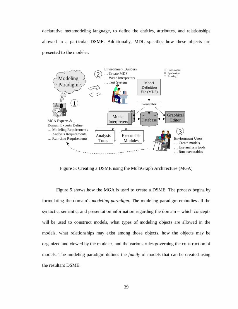
39
declarative metamodeling language, to define the entities, attributes, and relationships
allowed in a particular DSME. Additionally, MDL specifies how these objects are
presented to the modeler.
ModelingParadigm
MGA Experts &Domain Experts Define… Modeling Requirements… Analysis Requirements… Run-time Requirements
1
Environment Users… Create models… Use analysis tools… Run executables
3Analysis
ToolsExecutableModules
ModelDefinitionFile (MDF)
Database
Generator
GraphicalEditor
Environment Builders… Create MDF… Write Interpreters… Test System
2Hand-codedSynthesizedExisting
ModelInterpreters
Figure 5: Creating a DSME using the MultiGraph Architecture (MGA)
Figure 5 shows how the MGA is used to create a DSME. The process begins by
formulating the domain’s modeling paradigm. The modeling paradigm embodies all the
syntactic, semantic, and presentation information regarding the domain – which concepts
will be used to construct models, what types of modeling objects are allowed in the
models, what relationships may exist among those objects, how the objects may be
organized and viewed by the modeler, and the various rules governing the construction of
models. The modeling paradigm defines the family of models that can be created using
the resultant DSME.
40
Both domain- and MGA experts participate in the task of formulating the
modeling paradigm. Experience has shown that the modeling paradigm changes rapidly
during early stages of development, becoming stable only after a significant amount of
modeling environment prototyping and testing. Contributing to this phenomenon is the
fact that domain experts are often unable to initially specify exactly how the modeling
environment should behave. Of course, the modeling paradigm becomes more stable over
time. However, because of inevitable changes in the physical system being modeled,
neither the modeling paradigm nor the modeling environment can remain static – they
must change as the physical system changes. Such modeling environment evolution can
invalidate existing models, requiring models to be modified or, in many cases,
completely rebuilt. Model migration is very much an open issue.
Once a paradigm is decided upon, the environment builder creates a model
description file (MDF) using MDL. The MDF describes the paradigm’s model
construction semantics – what types of objects may be used to construct models, how
those objects will appear on-screen, and how they may be associated (i.e. connected) with
each other. The MDF also contains descriptions of any hierarchical and/or multi-aspect
model creation and viewing properties that must exist in the modeling environment
The MDF is used to automatically generate the model builder – a graphical model
editor – as well as the necessary database schema and database interface code. At this
point, the DSME can be used to create models of specific systems within the domain.
However, because the MDF specifies only the model construction semantics of the
modeling paradigm, no run-time meaning can be inferred from the models. Making sense
of the models, i.e. interpreting the models, is the job of the model interpreters – semantic
41
translators that access and process data from the populated model database for use by the
analysis tools and executable modules.
Although the MDF and the model interpreter code actually form an informal, de
facto specification for the DSME, there is no single specification that can be used to
formally validate the consistency of the modeling concepts represented by the MDF and
the model interpreters. Paradigm validation is necessary to ensure that the environment
sufficiently constrains the modeler so that only legal models can be created. Only a
careful examination of the MDF and considerable amounts of testing can uncover such
inconsistencies – a time consuming and error prone process. Another drawback of the
MGA is the amount of hand-coding required to create a DSME. Except for a small
amount of generated interpreter interface code, the MDF and all model interpreters are
written completely by hand.
Currently, MDL provides only limited support for the four-layer metamodeling
architecture. While it is possible to specify a graphical metamodeling environment using
MDL, such an environment would not support the specification of modeling language
semantics via provably correct invariant expressions. Instead, a metamodel's semantics
would have to be checked using one or more interpreters – clearly not a provable method,
since interpreters are written using C++, a high-level procedural programming language.
Also, a metamodel translator would need to be developed to ensure interoperability with
other metamodeling tools.
Meta Object Facility
The Object Management Group's newly adopted Meta Object Facility (MOF)
standard defines a CORBA-based, generic framework for describing and managing meta-
42
information [26][27]. While defined to represent many types of meta-information, such
as CORBA interface definitions, COM objects, and metadata for databases and
information services, MOF can also be used to represent and exchange models,
metamodels, and project management information for software development tools. These
formal models are created using special metamodeling constructs contained in the MOF
Model.
The MOF Model
The MOF Model is used to represent entity-relationship models. In other words,
the MOF Model is a metamodel. The MOF Model contains specific constructs for
creating metamodels – objects, described using MOF Classes to represent entities (which
are object types, not specific object instances); links, described using MOF Associations,
used to show relationships among objects; and data values, described by CORBA
Interface Description Language (IDL) Types.
MOF Classes allow named, attributed types to be defined in terms of the object's
operations and association references. MOF Classes act as containers for component
features (i.e. any attributes, operations, and association references). An MOF Class may
also contain MOF definitions of CORBA type definitions and exceptions.
MOF Associations are directed, binary associations between exactly two MOF
objects. Each Association has two named Association Ends that contain the end's name,
its type, its multiplicity (i.e. cardinality), and its aggregation (i.e. whether the end defines
a composite object). An MOF Association can be defined to be derived from other model
information, and it acts as a container for the two Association Ends.
43
Other MOF Model elements (called "secondary" elements) consist of Data Types
(used for Attribute and Operation parameters), Constants, Exceptions, and Constraints.
MOF Constraints are user-defined attachments to model elements. MOF does not require
the use of Constraints, and although the MOF Model typically uses OCL [28] as its
constraint language of choice, no particular constraint language is defined in MOF. Also,
there are also no requirements for any automated constraint checking, should the MOF
Model contain constraint specifications.
Just as an MOF Model is a metamodel, an MOF metamodel is actually a meta-
metamodel. MOF is a "complete" specification language, capable of defining itself via an
MOF metamodel. Such a representation is made using MOF's Meta-Object Definition
Language (MODL), a text-based language designed specifically for expressing MOF
metamodels. MODL is loosely based on the CORBA IDL syntax. Although MODL was
designed to represent MOF metamodels, MOF metamodels can also be represented using
the graphical notations of UML [29]. This technique is problematic, however, since, in
general, UML contains a richer, more complete set of modeling constructs than MOF. In
general, such an approach requires the modeler to carefully specify constraints describing
the limitations of MOF. Also, in a few cases, MOF has features that do not map directly
from UML (e.g. MOF Attributes and Associations can be derived – UML has no direct
representation for such constructs). Typically, this "extra" MOF information is
represented using UML Notes. Appendix "D" of [15] explains the metamodel
architectural alignment of UML, MOF, and CORBA, and contains various tables
comparing the core metaobjects and data types in each standard. The appendix also
covers various issues related to mapping between an MOF metamodel and the CDIF
44
meta-metamodel. It is interesting to note that although the metamodeling constructs of
MOF are a superset of the constructs found in the CDIF meta-metamodel, CDIF uses
significantly different (and sometimes non-object oriented) terminology.
MOF was designed to support the four-layer metamodeling architecture. MOF
supports the representation of both syntactic and semantic language specifications,
allowing, but not specifying, a constraint language. Therefore, no mechanism is specified
for composing MOF models from pre-specified, generalized modeling constraints. Also,
MOF model validation is totally dependent on the particular constraint language chosen.
Finally, MOF has no standard file-based format for metamodel interchange between
metamodeling tools. One solution proposed in [29] is to use the CDIF transfer syntax to
enable tool interoperability.
Formal Methods
Many formal languages exist for specifying a system's behavior. However, few
provide mechanisms that support the composition of metamodels from pre-specified,
generalized modeling constraints. Two notable exceptions are Specware [30][31], a
formal specification language based on category theory, and Larch [32], a module-based
formal specification language. Because formal methods represent a new and distinct
approach to metamodeling, readers unfamiliar with the terms and concepts of formal
methods are referred to Appendix B for a discussion of formal specification, formal
verification, and theorem proving.
There are four main goals when deciding on a formal language for use in defining
modeling languages (i.e. creating metamodels):
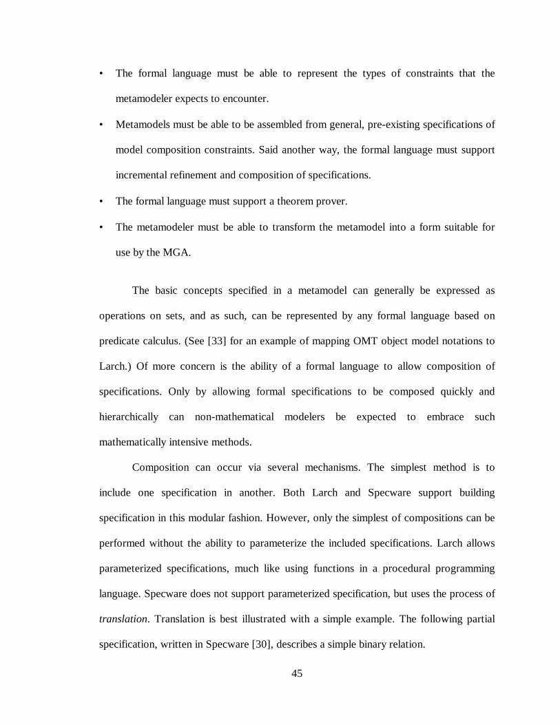
45
• The formal language must be able to represent the types of constraints that the
metamodeler expects to encounter.
• Metamodels must be able to be assembled from general, pre-existing specifications of
model composition constraints. Said another way, the formal language must support
incremental refinement and composition of specifications.
• The formal language must support a theorem prover.
• The metamodeler must be able to transform the metamodel into a form suitable for
use by the MGA.
The basic concepts specified in a metamodel can generally be expressed as
operations on sets, and as such, can be represented by any formal language based on
predicate calculus. (See [33] for an example of mapping OMT object model notations to
Larch.) Of more concern is the ability of a formal language to allow composition of
specifications. Only by allowing formal specifications to be composed quickly and
hierarchically can non-mathematical modelers be expected to embrace such
mathematically intensive methods.
Composition can occur via several mechanisms. The simplest method is to
include one specification in another. Both Larch and Specware support building
specification in this modular fashion. However, only the simplest of compositions can be
performed without the ability to parameterize the included specifications. Larch allows
parameterized specifications, much like using functions in a procedural programming
language. Specware does not support parameterized specification, but uses the process of
translation. Translation is best illustrated with a simple example. The following partial
specification, written in Specware [30], describes a simple binary relation.
46
spec BINARY-RELATION issorts Domain, Rangeop related? : Domain, Range -> Boolean
end-spec
This specification states that binary relations consist of domains and ranges
(Specware uses the sorts declaration to identify types). The Boolean operation
related? allows the specifier to assert that domains are related to ranges. Although
any metamodeling language must be capable of specifying binary relations among
modeling objects, a specification such as this is too general for use in a particular
metamodel. However, by importing and translating the sorts and operation contained in
this specification, a more domain-specific specification, called CONNECTION, can be
created. This process is called refinement, and is shown below.
spec CONNECTION istranslate BINARY-RELATION by{ Domain -> Source,
Range -> Destination,related? -> connected? }
end-spec
The resultant spec, CONNECTION, can now be used to specify a connection that
consists of a source connected to a destination. Of course, the specification can be refined
further, to apply the CONNECTION specification to a particular Source-
Destination pair.
Although not specifically designed to support metamodeling, formal languages
such as Specware and Larch can be used to specify the syntactic and semantic behavior
of a modeling language as invariant predicate expressions. The problem is one of scale.
Formal languages require low-level definitions of such behavior, and an accompanying
47
mathematical description of the mechanisms supporting such behavior. Without the
ability to compose basic, generalized specifications of behavior (i.e. relationships,
hierarchy, object association, etc.) into domain-specific, higher-level specifications,
metamodelers cannot be expected to use formal methods. One popular method of
including formal methods in software design is to use them to specify only the most
critical portions of a design [34]. Also, both Larch and Specware include proof-checkers,
allowing the consistency of metamodels to be validated. However, neither language
supports the exchange of specifications with other formal methods languages.
Unified Modeling Language
The Unified Modeling Language is an OMG-approved modeling language for
specifying, constructing, visualizing, and documenting the artifacts of a software-
intensive system [22][23]. It combines concepts from the Booch Method, Rumbaugh's
Object Modeling Technique, and Jacobson's Object Oriented Software Engineering
method. UML supports many modeling notions, such as use-case diagrams, class
diagrams, behavior diagrams (including state charts, state machines, activity diagrams,
sequence charts, and collaboration diagrams), and implementation diagrams. UML is a
specification language, and as such it does not cover tool specifications, diagram layouts,
coloring, user navigation, and other presentation issues.
UML supports the four-layer metamodeling architecture, and UML can be used to
model itself [28][3]. When modeling a modeling language, UML has facilities for
capturing the syntax and the semantics of the modeled language. The language's syntax is
captured in the form of graphical, entity-attribute-relationship and behavioral diagrams,
and the language's semantics are represented as invariant predicate logic expressions
48
using the Object Constraint Language (OCL). Because UML provides no method for
incorporating constraints into the graphical models, there is a natural separation between
syntactic and semantic specifications. (It is up to the implementation environment to
provide support for consistency checking between entity and relationship identifiers in
the graphical models and the semantic constraint specifications.)
UML does not identify any method for composing metamodels from generalized,
graphical modeling specifications. This stems primarily from the fact that no standardized
textual representation of the UML is specified. Therefore, no method of creating
parameterized specifications is possible. While this could be considered an
implementation detail, it actually represents a serious drawback when trying to use UML
as a metamodeling language. Rational Rose [23], a UML modeling tool produced by the
Rational company (whose founders are also the designers of UML), uses a somewhat
proprietary file format called Rational Petal, and although Rational licenses the Petal
technology, it is not in the public domain. To enable tool interoperability, the UML
developers have created a UML-compliant tool interface definition using the CDIF
standard.
Object Constraint Language
As mentioned above, UML uses OCL to specify modeling language semantics.
OCL is a public domain, formal language specification, used to express constraints and
other expressions associated with graphical models. OCL is a textual language, designed
to be used in conjunction with, but independent of, UML. The full OCL specification can
be found in [28]. OCL is a full-featured declarative language, capable of creating
expressions that represent complex relationships among object types (OCL can also be
49
used to create constraints on instances of those types). Although OCL is formal, and has
an exact syntax, it was designed to be easily read and understood by human designers.
OCL is not a programming language, and OCL expressions have no effect on the
actual system design. The expressions are merely formal comments on the construction
and behavior of the system and its components. Designers make statements about
required states of models, but OCL cannot cause any state changes in those models. Since
OCL is a typed language, for OCL expressions to be correct they must be type
conformant (e.g. a designer cannot compare string values with Boolean values).
Enumerated types are also supported.
OCL statements represent invariant Boolean expressions that specify the
semantics of a modeling language. As an example, consider the MGA audio processing
modeling paradigm discussed earlier. It was mentioned that an important consideration
when creating actual audio systems is that power amplifier outputs must be connected to
something (i.e. power amps should not operated without a load). The following OCL
expression states such a requirement.
PowerAmp.allInstances->forAll(p | p.OutputConnections->size > 0)
This expression states that the number of output connections associated with each
instance of a PowerAmp-type object must be greater than zero. Note that this expression
represents a condition that must exist in all models created using this audio processing
modeling paradigm. Also, such a constraint can only be verified in the presence of an
actual audio model – an instance of the metamodel describing this domain-specific
modeling environment.
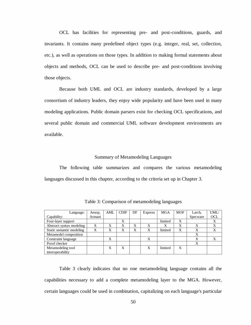
50
OCL has facilities for representing pre- and post-conditions, guards, and
invariants. It contains many predefined object types (e.g. integer, real, set, collection,
etc.), as well as operations on those types. In addition to making formal statements about
objects and methods, OCL can be used to describe pre- and post-conditions involving
those objects.
Because both UML and OCL are industry standards, developed by a large
consortium of industry leaders, they enjoy wide popularity and have been used in many
modeling applications. Public domain parsers exist for checking OCL specifications, and
several public domain and commercial UML software development environments are
available.
Summary of Metamodeling Languages
The following table summarizes and compares the various metamodeling
languages discussed in this chapter, according to the criteria set up in Chapter 3.
Table 3: Comparison of metamodeling languages
Language:Capability:
Aesop,Armani
AML CDIF DF Express MGA MOF Larch,Specware
UML/OCL
Four-layer support X limited X XAbstract syntax modeling X X X X X X X X XStatic semantic modeling X X X X X limited X X XMetamodel composition XConstraint language X X X XProof checker XMetamodeling toolinteroperability
X X X limited X
Table 3 clearly indicates that no one metamodeling language contains all the
capabilities necessary to add a complete metamodeling layer to the MGA. However,
certain languages could be used in combination, capitalizing on each language's particular
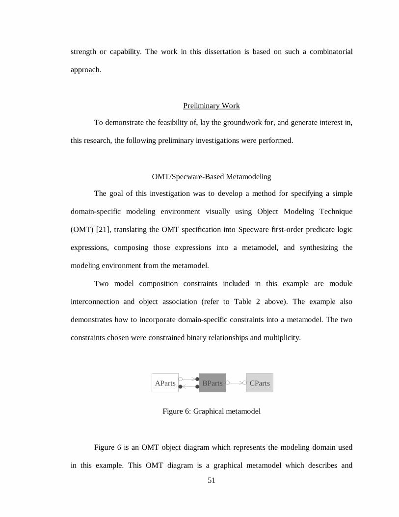
51
strength or capability. The work in this dissertation is based on such a combinatorial
approach.
Preliminary Work
To demonstrate the feasibility of, lay the groundwork for, and generate interest in,
this research, the following preliminary investigations were performed.
OMT/Specware-Based Metamodeling
The goal of this investigation was to develop a method for specifying a simple
domain-specific modeling environment visually using Object Modeling Technique
(OMT) [21], translating the OMT specification into Specware first-order predicate logic
expressions, composing those expressions into a metamodel, and synthesizing the
modeling environment from the metamodel.
Two model composition constraints included in this example are module
interconnection and object association (refer to Table 2 above). The example also
demonstrates how to incorporate domain-specific constraints into a metamodel. The two
constraints chosen were constrained binary relationships and multiplicity.
AParts BParts CParts
Figure 6: Graphical metamodel
Figure 6 is an OMT object diagram which represents the modeling domain used
in this example. This OMT diagram is a graphical metamodel which describes and
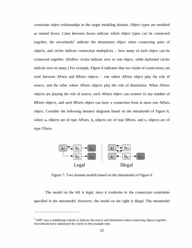
52
constrains object relationships in the target modeling domain. Object types are modeled
as named boxes. Lines between boxes indicate which object types can be connected
together, the arrowheads2 indicate the destination object when connecting pairs of
objects, and circles indicate connection multiplicity – how many of each object can be
connected together. (Hollow circles indicate zero or one object, while darkened circles
indicate zero to many.) For example, Figure 6 indicates that two kinds of connections can
exist between AParts and BParts objects – one where AParts object play the role of
source, and the other where AParts objects play the role of destination. When AParts
objects are playing the role of source, each AParts object can connect to any number of
BParts objects, and each BParts object can have a connection from at most one AParts
object. Consider the following instance diagrams based on the metamodel of Figure 6,
where an objects are of type AParts, bn objects are of type BParts, and cn objects are of
type CParts.
a2
a3
b3
c3
a1 b1 c1
b4b2 c2
IllegalLegal
Figure 7: Two domain models based on the metamodel of Figure 6
The model on the left is legal, since it conforms to the connection constraints
specified in the metamodel. However, the model on the right is illegal. The metamodel
2 OMT uses a numbering scheme to indicate the source and destination when connecting objects together.Arrowheads have substituted for clarity in this example only.
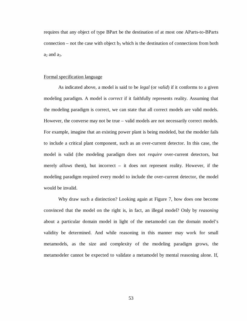
53
requires that any object of type BPart be the destination of at most one AParts-to-BParts
connection – not the case with object b3 which is the destination of connections from both
a2 and a3.
Formal specification language
As indicated above, a model is said to be legal (or valid) if it conforms to a given
modeling paradigm. A model is correct if it faithfully represents reality. Assuming that
the modeling paradigm is correct, we can state that all correct models are valid models.
However, the converse may not be true – valid models are not necessarily correct models.
For example, imagine that an existing power plant is being modeled, but the modeler fails
to include a critical plant component, such as an over-current detector. In this case, the
model is valid (the modeling paradigm does not require over-current detectors, but
merely allows them), but incorrect – it does not represent reality. However, if the
modeling paradigm required every model to include the over-current detector, the model
would be invalid.
Why draw such a distinction? Looking again at Figure 7, how does one become
convinced that the model on the right is, in fact, an illegal model? Only by reasoning
about a particular domain model in light of the metamodel can the domain model’s
validity be determined. And while reasoning in this manner may work for small
metamodels, as the size and complexity of the modeling paradigm grows, the
metamodeler cannot be expected to validate a metamodel by mental reasoning alone. If,
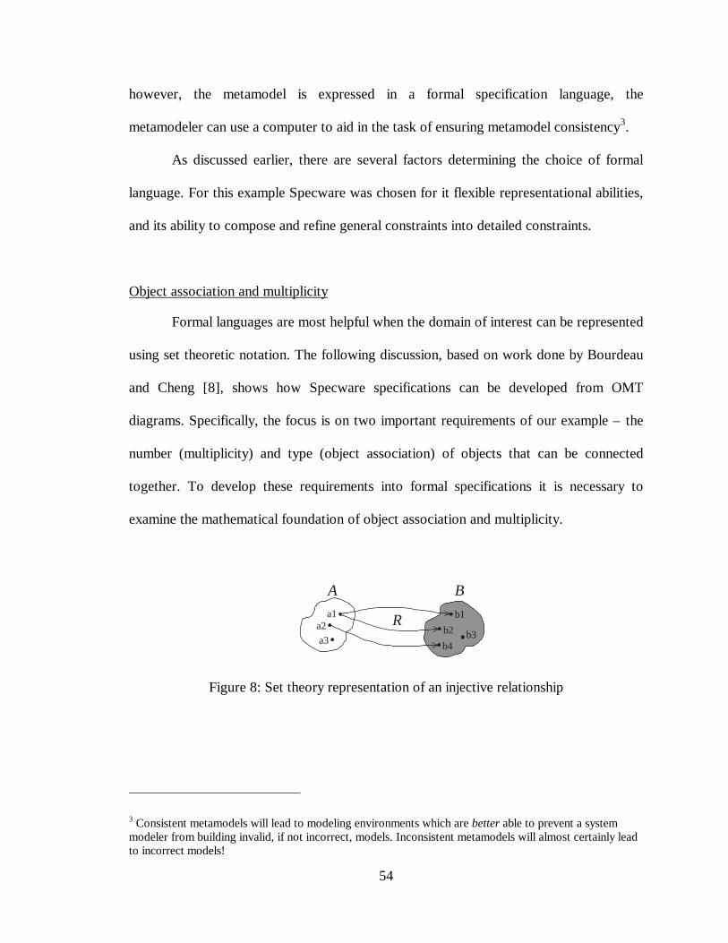
54
however, the metamodel is expressed in a formal specification language, the
metamodeler can use a computer to aid in the task of ensuring metamodel consistency3.
As discussed earlier, there are several factors determining the choice of formal
language. For this example Specware was chosen for it flexible representational abilities,
and its ability to compose and refine general constraints into detailed constraints.
Object association and multiplicity
Formal languages are most helpful when the domain of interest can be represented
using set theoretic notation. The following discussion, based on work done by Bourdeau
and Cheng [8], shows how Specware specifications can be developed from OMT
diagrams. Specifically, the focus is on two important requirements of our example – the
number (multiplicity) and type (object association) of objects that can be connected
together. To develop these requirements into formal specifications it is necessary to
examine the mathematical foundation of object association and multiplicity.
a1a2
Ab1
b2
B
a3 b4b3
R
Figure 8: Set theory representation of an injective relationship
3 Consistent metamodels will lead to modeling environments which are better able to prevent a systemmodeler from building invalid, if not incorrect, models. Inconsistent metamodels will almost certainly leadto incorrect models!
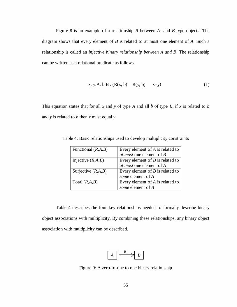
55
Figure 8 is an example of a relationship R between A- and B-type objects. The
diagram shows that every element of B is related to at most one element of A. Such a
relationship is called an injective binary relationship between A and B. The relationship
can be written as a relational predicate as follows.
∀ x, y:A, b:B . (R(x, b) ∧ R(y, b) ⇒ x=y) (1)
This equation states that for all x and y of type A and all b of type B, if x is related to b
and y is related to b then x must equal y.
Table 4: Basic relationships used to develop multiplicity constraints
Functional (R,A,B) Every element of A is related toat most one element of B
Injective (R,A,B) Every element of B is related toat most one element of A
Surjective (R,A,B) Every element of B is related tosome element of A
Total (R,A,B) Every element of A is related tosome element of B
Table 4 describes the four key relationships needed to formally describe binary
object associations with multiplicity. By combining these relationships, any binary object
association with multiplicity can be described.
A BR1
Figure 9: A zero-to-one to one binary relationship
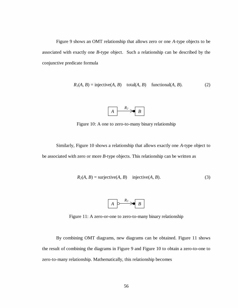
56
Figure 9 shows an OMT relationship that allows zero or one A-type objects to be
associated with exactly one B-type object. Such a relationship can be described by the
conjunctive predicate formula
R1(A, B) = injective(A, B) ∧ total(A, B) ∧ functional(A, B). (2)
A BR2
Figure 10: A one to zero-to-many binary relationship
Similarly, Figure 10 shows a relationship that allows exactly one A-type object to
be associated with zero or more B-type objects. This relationship can be written as
R2(A, B) = surjective(A, B) ∧ injective(A, B). (3)
A BR3
Figure 11: A zero-or-one to zero-to-many binary relationship
By combining OMT diagrams, new diagrams can be obtained. Figure 11 shows
the result of combining the diagrams in Figure 9 and Figure 10 to obtain a zero-to-one to
zero-to-many relationship. Mathematically, this relationship becomes
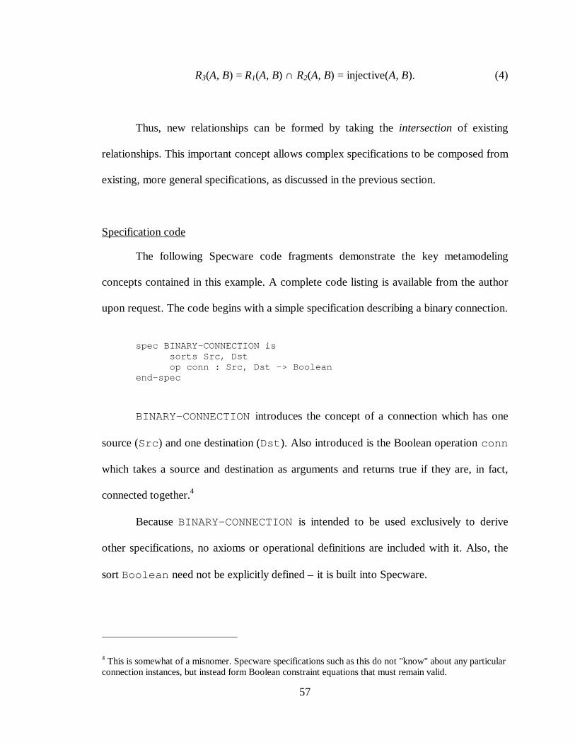
57
R3(A, B) = R1(A, B) ∩ R2(A, B) = injective(A, B). (4)
Thus, new relationships can be formed by taking the intersection of existing
relationships. This important concept allows complex specifications to be composed from
existing, more general specifications, as discussed in the previous section.
Specification code
The following Specware code fragments demonstrate the key metamodeling
concepts contained in this example. A complete code listing is available from the author
upon request. The code begins with a simple specification describing a binary connection.
spec BINARY-CONNECTION issorts Src, Dstop conn : Src, Dst -> Boolean
end-spec
BINARY-CONNECTION introduces the concept of a connection which has one
source (Src) and one destination (Dst). Also introduced is the Boolean operation conn
which takes a source and destination as arguments and returns true if they are, in fact,
connected together.4
Because BINARY-CONNECTION is intended to be used exclusively to derive
other specifications, no axioms or operational definitions are included with it. Also, the
sort Boolean need not be explicitly defined – it is built into Specware.
4 This is somewhat of a misnomer. Specware specifications such as this do not "know" about any particularconnection instances, but instead form Boolean constraint equations that must remain valid.
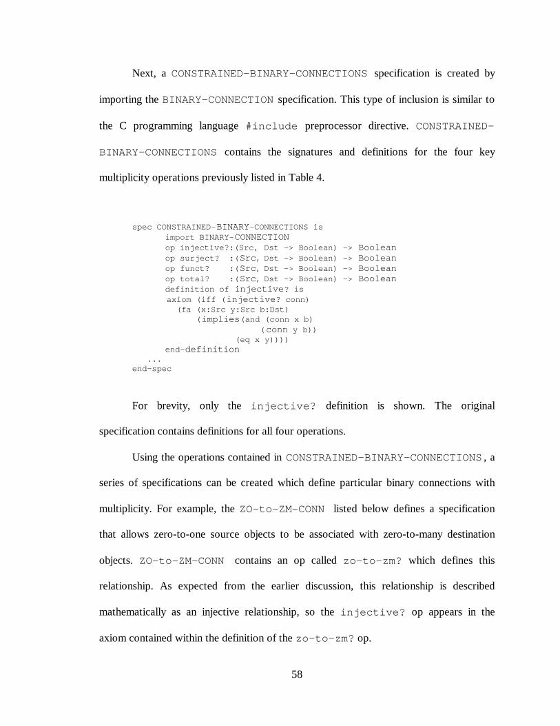
58
Next, a CONSTRAINED-BINARY-CONNECTIONS specification is created by
importing the BINARY-CONNECTION specification. This type of inclusion is similar to
the C programming language #include preprocessor directive. CONSTRAINED-
BINARY-CONNECTIONS contains the signatures and definitions for the four key
multiplicity operations previously listed in Table 4.
spec CONSTRAINED-BINARY-CONNECTIONS isimport BINARY-CONNECTIONop injective?:(Src, Dst -> Boolean) -> Booleanop surject? :(Src, Dst -> Boolean) -> Booleanop funct? :(Src, Dst -> Boolean) -> Booleanop total? :(Src, Dst -> Boolean) -> Booleandefinition of injective? is
axiom (iff (injective? conn) (fa (x:Src y:Src b:Dst) (implies(and (conn x b) (conn y b)) (eq x y))))
end-definition ...end-spec
For brevity, only the injective? definition is shown. The original
specification contains definitions for all four operations.
Using the operations contained in CONSTRAINED-BINARY-CONNECTIONS , a
series of specifications can be created which define particular binary connections with
multiplicity. For example, the ZO-to-ZM-CONN listed below defines a specification
that allows zero-to-one source objects to be associated with zero-to-many destination
objects. ZO-to-ZM-CONN contains an op called zo-to-zm? which defines this
relationship. As expected from the earlier discussion, this relationship is described
mathematically as an injective relationship, so the injective? op appears in the
axiom contained within the definition of the zo-to-zm? op.
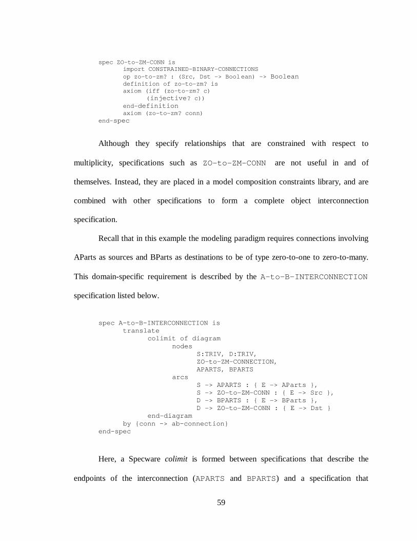
59
spec ZO-to-ZM-CONN isimport CONSTRAINED-BINARY-CONNECTIONSop zo-to-zm? : (Src, Dst -> Boolean) -> Booleandefinition of zo-to-zm? isaxiom (iff (zo-to-zm? c)
(injective? c))end-definitionaxiom (zo-to-zm? conn)
end-spec
Although they specify relationships that are constrained with respect to
multiplicity, specifications such as ZO-to-ZM-CONN are not useful in and of
themselves. Instead, they are placed in a model composition constraints library, and are
combined with other specifications to form a complete object interconnection
specification.
Recall that in this example the modeling paradigm requires connections involving
AParts as sources and BParts as destinations to be of type zero-to-one to zero-to-many.
This domain-specific requirement is described by the A-to-B-INTERCONNECTION
specification listed below.
spec A-to-B-INTERCONNECTION istranslate
colimit of diagramnodes
S:TRIV, D:TRIV,ZO-to-ZM-CONNECTION,APARTS, BPARTS
arcsS -> APARTS : { E -> AParts },S -> ZO-to-ZM-CONN : { E -> Src },D -> BPARTS : { E -> BParts },D -> ZO-to-ZM-CONN : { E -> Dst }
end-diagramby {conn -> ab-connection}
end-spec
Here, a Specware colimit is formed between specifications that describe the
endpoints of the interconnection (APARTS and BPARTS) and a specification that
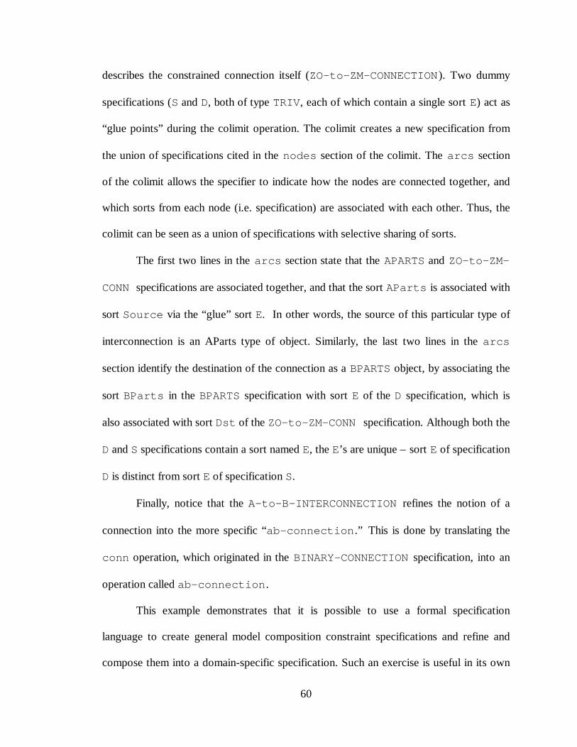
60
describes the constrained connection itself (ZO-to-ZM-CONNECTION). Two dummy
specifications (S and D, both of type TRIV, each of which contain a single sort E) act as
“glue points” during the colimit operation. The colimit creates a new specification from
the union of specifications cited in the nodes section of the colimit. The arcs section
of the colimit allows the specifier to indicate how the nodes are connected together, and
which sorts from each node (i.e. specification) are associated with each other. Thus, the
colimit can be seen as a union of specifications with selective sharing of sorts.
The first two lines in the arcs section state that the APARTS and ZO-to-ZM-
CONN specifications are associated together, and that the sort AParts is associated with
sort Source via the “glue” sort E. In other words, the source of this particular type of
interconnection is an AParts type of object. Similarly, the last two lines in the arcs
section identify the destination of the connection as a BPARTS object, by associating the
sort BParts in the BPARTS specification with sort E of the D specification, which is
also associated with sort Dst of the ZO-to-ZM-CONN specification. Although both the
D and S specifications contain a sort named E, the E’s are unique – sort E of specification
D is distinct from sort E of specification S.
Finally, notice that the A-to-B-INTERCONNECTION refines the notion of a
connection into the more specific “ab-connection.” This is done by translating the
conn operation, which originated in the BINARY-CONNECTION specification, into an
operation called ab-connection.
This example demonstrates that it is possible to use a formal specification
language to create general model composition constraint specifications and refine and
compose them into a domain-specific specification. Such an exercise is useful in its own
61
right, to establish the credibility of a modeling paradigm, to allow formal reasoning of a
specification, and to document the system’s design in a formal way. However, this is not
enough. The metamodeler must be able to take this formal specification and translate it
for use in synthesizing the actual domain-specific modeling environment. This is
discussed below.
Mediator and MDF generation
Only by generating an MDF can a modeling paradigm’s formal specification be
fully utilized. Generating an MDF from a formal specification requires detailed
knowledge about the application programming interface (API) used by the specification
language, so that key information may be extracted from the final metamodel
specification and used to generate the MDF.
Specware was written using Refine [35], a programming environment for
language design which uses BNF-like notational descriptions of the target language’s
grammar. Because of this, a Refine-based mediator had to be written to examine the
resulting Specware data structures, extract the information necessary to generate an
MDF, and to generate the MDF itself. Because Specware is an emerging technology,
little formal documentation was available on the API used to access the underlying data
structures. However, with the help of Specware researchers at the Kestrel Institute, a
mediator was developed to generate MDF files from simple specifications – simpler
specifications than the example just presented. (The modeling paradigm was the same,
but the source specifications contained only carefully written axioms from which the
MDF information could be easily extracted.) The generated MDF was then used with the
MGA to synthesize a modeling environment which conformed to the specified modeling
62
paradigm. A more detailed mediator, capable of creating an MDF from the specifications
presented in this proof-of-concept example was planned, but not completed.
A GME/MCL Metamodeling Environment
An undesirable feature of the OMT/Specware metamodeling approach is that
every detail of the target modeling language has to be formalized and expressed as a set
of Boolean predicate logic equations. While predicate logic is well suited to expressing
the semantics of a modeling language, the syntax and presentation specifications need not
be so formally described. This section describes another method that was investigated for
metamodeling – to use the GME modeling environment to model a domain-specific
modeling language.
A GME modeling paradigm capable of modeling other GME modeling paradigms
must have a way to model the target language's semantics, and later, when the target
environment is synthesized and used for modeling, those constraints must be enforced.
Although the existing MGA tool suite appeared suitable for specifying syntax and
presentation requirements, no method existed for specifying and enforcing semantic
constraints.
The solution required three modifications to the existing MGA tools. First, a
predicate logic constraint language had to be specified and incorporated into the GME.
Second, a metamodeling paradigm capable of specifying GME-based modeling
languages had to be created. And third, a model interpreter had to be written that could
synthesize the target modeling environment from the metamodel.
OCL was investigated for use as the semantic constraint language. It was
determined that OCL had the necessary constructs, but lacked any ability to supply any
63
scope information. Therefore, a modified version of OCL was developed – the MGA
Constraint Language (MCL). MCL is strongly based on OCL. Analysis of MGA
metamodeling requirements showed that only a subset of OCL would be necessary to
express the necessary constraints, but that some additions were needed to efficiently
apply OCL to a GME-based metamodeling environment. To that end, functions were
added to MCL allowing the metamodeler to specify groups of modeling objects typically
found in metamodels. Two such functions are parts("partType") and
models("modelType"), both of which represent a collection of modeling objects of a
certain type. It was decided that the constraints would be included within the metamodel,
not specified separately, allowing the constraints to take on a contextual scope depending
on where they appeared within the metamodel. MCL constraint expressions appear inside
context specifying "wrappers" and have the following general form:
[in category[.model[.aspect]]]on event constraint name([arguments])priority=0|1|2|3"errorText" {
expression}
The square brackets indicate optional items. The terms category, model, and
aspect refer to the GME category, model, and aspect where the constraint is found (i.e.
the context where the constraint applies). event refers to the type of event that triggers a
check of the constraint, e.g. on_demand (when specifically requested by the modeler),
on_create (when a model is created), on_save (when a model is saved), etc.
constraint is a required keyword, name is the name of the particular constraint, and
arguments is a comma separated list of optional arguments, allowing one constraint to
64
refer to another. The priority statement determines when a particular constraint
expression is checked relative to other constraints. In this way, a temporal relationship
may be established among constraints, where constraints with a higher priority (i.e. a
larger priority number) are checked before lower priority constraints. errorText is a
double-quoted string containing text that is displayed when the constraint is violated.
expression is the actual Boolean constraint expression.
The final modification to the MGA modeling tool was the creation and addition of
a constraint manager (CM). The behavior of the CM is specified in the metamodel by
writing constraints as just described. Once the target modeling environment has been
synthesized from the metamodel, the CM is configured from the constraints, and the CM
monitors the user's model editing actions, alerting him/her whenever a constraint is
violated.
The GME/MCL metamodeling paradigm allows the metamodeler to specify
objects in the target environment as attributed entities representing atomic parts, models,
reference parts, attributes, and categories. Relationships among these objects are modeled
as connections or conditionalizations (collections of dissimilar modeling objects). In the
case of atomic parts, a visualization object must be attached to the atomic part, indicating
how the part will appear in the target modeling environment.
Object hierarchy is modeled via containment. Categories contain Models, Models
contain Aspects, and Aspects contain parts, connections, and conditional groups. Note
that although Aspects are modeled as first-class modeling objects, in reality they are
merely a visualization technique, not actual GME modeling entities. This approach was
taken because (1) it was much simpler to design a metamodeling paradigm where

65
hierarchical containment was uniformly applied to Categories, Models, and Aspects, and
(2) novice metamodelers5 typically think of and use Aspects as "real" objects, so this
approach enables them to more rapidly construct metamodels.6 Also, modeling Aspects
in this way does not detract from their use, or restrict their functionality in any way.
5 Those who have never created a modeling paradigm "by hand," using a purely textual representation.6 Expert metamodelers also found this representation intuitive and useful.
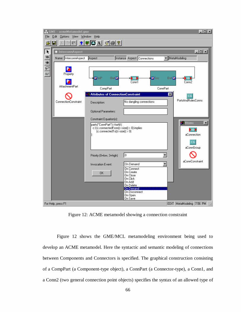
66
Figure 12: ACME metamodel showing a connection constraint
Figure 12 shows the GME/MCL metamodeling environment being used to
develop an ACME metamodel. Here the syntactic and semantic modeling of connections
between Components and Connectors is specified. The graphical construction consisting
of a CompPart (a Component-type object), a ConnPart (a Connector-type), a Conn1, and
a Conn2 (two general connection point objects) specifies the syntax of an allowed type of
67
connection in the ACME modeling language, while the ConnectionConstraint (whose
attribute box is shown opened for editing) is used to specify the connection's semantics.
This particular constraint states that if an ACME Connector has a connection to its Src
role (i.e. a connection exists from another object to the Connector object) then a
connection must also exist from the ACME Connector to another object. Thus the
constraint name "No dangling connections."
Analysis and Lessons Learned
The OMT/Specware metamodeling environment research successfully
demonstrated the feasibility of several key metamodeling concepts, such as formal
specification of modeling constraints, composition and refinement of specifications, and
automatic synthesis of domain-specific modeling environments from metamodels.
Analysis of the resulting metamodels showed that although such a predicate logic based
metamodel lends itself to computer aided consistency and validation checking, because it
consisted entirely of Boolean predicate equations, the metamodel contained far too much
low-level detail, and was not easily understood by humans unfamiliar with first-order
predicate logic. Also, although metamodel composition was shown to be a viable method
for constructing metamodels, the composition techniques used were not generalizable,
but relied heavily on Specware-specific composition and refinement techniques. Overall,
the OMT/Specware method was deemed unsuitable for use as a general metamodeling
method. Nonetheless, the concepts of composing a metamodel by combining and refining
general model composition constraints, and generating a domain-specific modeling
environment from the metamodel, were successfully demonstrated.
68
The GME/MCL-based metamodeling environment showed much more promise.
Using graphical constructs to specify modeling language syntax was shown to be a viable
technique for creating metamodels – a technique that did not unduly burden the
metamodeler with low-level formal details. Specifying syntactic and presentation
requirements graphically was easier and more intuitive than the Boolean equation
refinement method used in the OMT/Specware-based metamodeling environment. By
employing MCL to specify semantic constraints, metamodelers were able to create
metamodels that properly constrained users of the target modeling environment,
preventing illegal models from being created.
Although an improvement over the OCL/Specware approach, the GME/MCL
method had several drawbacks. The graphical notation used for syntactic specification
was non-standard and, in some cases, non-intuitive. The GME/MCL metamodeling
paradigm itself conformed very closely to the MDF syntax and structure, providing
essentially the same design choices that are available when creating and MDF by hand
(with one important exception – the MDF has no facility for including MCL constraint
expressions). This required the metamodeler to be quite familiar with the MDF syntax
and semantics, as well as the GME/MCL metamodel construction rules, to ensure success
when creating metamodels. In practice, novice metamodelers faced a fairly steep learning
curve when using the GME/MCL metamodeling environment, but were generally
successful at creating complex metamodels. Expert metamodelers were also successful,
but complained that the system seemed more burdensome than simply creating an MDF
file by hand. Again, this is because the metamodeling environment provided the
metamodeler with few new ways of thinking about modeling language design.

69
The most severe drawback of the GME/MCL metamodeling environment was its
inability to cleanly separate the three language specification components – semantics,
syntax, and presentation – from one another. In many cases, presentation requirements
were stated in the same design context as semantic and/or syntactic requirements. This
had the effect of blurring the design process, forcing the language designer to design in
multiple domains simultaneously, making it difficult to think and design abstractly during
the early stages of metamodel design. It should be noted that this is also a significant
drawback when creating MDF files by hand.
70
CHAPTER III
UML/GME METAMODELING
Based on lessons learned in creating the OMT/Specware and GME/MCL
metamodeling environments, a metamodeling environment based on UML and the GME
has been created. The general design methodology utilizes UML to specify the modeling
language syntax and MCL to specify semantics. Presentation specifications take the form
of a mapping between the UML entities and relationships and GME objects representing
elements of the target modeling environment. This approach provides the necessary
division between the semantic, syntactic, and presentational elements of the desired
language, thus allowing the language designer to focus on one aspect of the language
design problem at a time, while simultaneously being able to monitor and track the
progress of the overall design. Also, because UML is a well known and widely accepted
modeling language, end users can more easily participate in and contribute to the
modeling language specification process.
Before discussing the details of specifying language components in the
UML/GME metamodeling environment, and the general strategy for mapping the UML-
based design notions onto GME modeling objects, it is necessary to understand the
various resources available in a general GME-based MIPS modeling environment.
Modeling Environment Resources
Various capabilities exist in every GME-based MIPS modeling environment. To
the metamodeler, these appear as modeling environment resources that can be used (i.e.
71
mapped onto) to express and realize the various features of a particular modeling
language. These include the ability to create and edit multi-aspect models of domain-
specific systems, to compose models using standardized modeling techniques such as
hierarchical decomposition and module interconnection, to specify modeling language
constraints which will be enforced when the target language is used for modeling, to store
and retrieve models from persistent storage, and to perform semantic translation on the
models. This semantic translation represents a second mapping – an automatic mapping
performed by one or more model interpreters. This is discussed in more detail in Chapter
IV.
Model Creation and Visualization
The Graphical Model Editor
In any visual modeling environment, the key element is the graphical editor used
to create the domain-specific models. Generally, this editor serves two purposes: to
control the modeler's access to the various editing capabilities of the environment, and to
provide visual feedback on the current state of any models being created. In both the
UML/GME metamodeling environment, and in the target modeling environment, the
GME is used for graphical modeling. Refer to [36] for more information on using the
GME as part of the MGA metaprogrammable toolkit.
The GME is a configurable editor, taking behavioral cues from various
specifications contained in the metamodel. The metamodel must specify the types and
characteristics of all modeling parts, part references, and part collections, as well as
allowed connections and relationships between parts. Depending on the type of model
72
being designed, the GME presents the modeler with a parts collection applicable to the
current design context (e.g. the type of model, the current aspect, etc.) For example, an
automobile design system may allow various types of models to be created, such as brake
system models, powertrain models, etc. When creating a brake system model, only
components associated with the brake system, such as a brake pedal, brake fluid
reservoir, etc., are available for inclusion in the model. Parts such as transmissions,
driveshafts, etc., although part of the overall automobile model, are not available when
designing brake models.
In addition to contextually controlling the availability of parts, the GME also
contextually controls parts availability within a model. Here, certain parts may be
available and/or visible in one design context but unavailable or hidden in others. These
model-specific contexts are called aspects.
Multi-Aspect Modeling
The modeling paradigm states how various components of a modeling
environment are presented to the modeler. The model design space is partitioned into
aspects – separate design spaces within a particular model. Depending on the aspect
chosen, certain modeling parts, part references, and/or relationships (e.g.
conditionalizations and/or connections) may or may not be allowed.
More than one aspect can exist within a particular model. For example, consider
again the automobile brake system example. Braking systems consist of both mechanical
and electrical components and subsystems. Therefore, a brake system modeling paradigm
would specify two aspects for a brake model – a mechanical aspect and an electrical
aspect. When the mechanical aspect is activated, only the mechanical parts of the system
73
are visible, and only mechanical models can be constructed. Similarly, when the
electrical aspect is selected, only electrical modeling components are visible and
available. However, the underlying brake model contains both mechanical and electrical
components; which ones are visible is determined by the current aspect. Note that in
some cases it is necessary for parts to be visible in multiple aspects (e.g. the brake light
switch is an integral part of both the electrical and mechanical subsystems, and should
therefore appear in both aspects). To enable this behavior, parts are designated as
inherited across aspects. Each part has a primary aspect where it is first created, but can
also be used in other aspects if properly identified (in the metamodel) as inherited.
Model Composition
To manage the complexity associated with models, various model composition
capabilities are available to the modeler. Object containment provides information hiding
and design abstraction by allowing objects to contain other objects, enabling the modeler
to selectively view or hide the model's constituent parts. The MGA provides part-whole
hierarchy support in two ways – through the use of Models and through
Conditionalization.
Model Hierarchy
A Model acts as a container for various types of modeling parts – atomic parts,
other models, or references to other parts and/or models. Underlying data structures
associated with each Model object contain lists of the various parts contained within the
Model. These data structures are automatically updated as Model objects are created,
edited, and/or deleted. Visually, when one model contains another, the GME represents
74
the contained model as a solid rectangular box, the contents of which can only be seen by
"opening" that model. An exception to this behavior occurs when the contained Model
itself contains link parts. Links are specially marked atomic parts that can be connected
to external parts (i.e. parts of other Models). When one Model contains another Model
that contains link parts, the link parts appear on the edges of the contained Model's
rectangle, forming attachment points for external connections.
Module Interconnection
Link parts are the mechanism for providing support for module interconnection,
one of the general modeling composition constraints listed in Table 2. Through the use of
object hierarchy and link parts, modeling paradigms can be developed which implement
module interconnection schemes. Note that only atomic parts can be designated as link
parts, and that link parts only appear as connection points one level up in the containment
hierarchy. For example, consider three Models, A, B, and C. If A contains B, and B
contains C, and C contains link parts x and y, x and y will be visible on the edges of C
when C is viewed from within B, but not when B is viewed from within A.
Conditionalization
The second method for providing part-whole hierarchy is through
conditionalization. Conditionalization refers to the collecting of atomic parts, models,
references, and connections into named groups. A special conditional controller part,
which itself can be an atomic- or reference part, is designated as the "owner" or
"controller" of the parts collection. To add or remove parts from the conditionalization
group, the GME must first be put into "conditional mode" (one of the editing modes
75
available to the modeler). Next the controller must be selected and activated. Once
activated, the modeler can then mark/unmark various parts and connection types for
inclusion in the conditionalization group.
As an example of conditionalization, consider a power distribution modeling
environment consisting of transformers, transmission lines, and switches. Atomic parts
are used to represent transformers and switches, while connections between transformers
and switches represent transmission lines. Suppose it is necessary to designate certain
groups of transformers, switches, and transmission lines as "mission critical" groups,
while other groups must be designated as "non-critical." One could design a modeling
paradigm containing two types of transformers, switches, and connections – one type to
be used when constructing mission critical power diagrams and the other type used when
constructing non-critical diagrams. This scheme breaks down, however, when a single
component must be a member of both groups (e.g. a transformer feeds both a mission
critical circuit and a non-critical circuit – the same transformer must have membership in
two groups). Without conditionalization, modeling this type of situation would be
complicated and non-intuitive. With conditionalization, however, the solution is
straightforward. The modeler creates two conditionalization groups, each with its own
controller part, and marks parts as belonging to one or both groups. This assumes, of
course, that the metamodel specifies such groups to exist and contain similar types of
parts.
Constraint Management
As mentioned earlier, constraints are used in a metamodel to specify the
semantics of a particular modeling language. These Boolean predicate expressions
76
represent invariant conditions which must hold for models to be legal in the given
paradigm. In practice, however, the modeler is usually able to create both legal and
illegal models. Therefore, some mechanism must exist to ensure that the semantic
constraints contained in the metamodel are enforced during model creation time. This is
the job of the constraint manager (CM).
Constraints are supplied to the CM from the metamodel. The metamodeler must
ensure a proper correlation between the object and type names used in the constraint
equations and the object and type names used in the GME. (In the current UML/GME
metamodeling system, constraints are simply text strings associated with the metamodel –
no type checking is performed to ensure that object names used in a constraint properly
correlate to named objects in the paradigm). During metamodel interpretation, these
constraints are extracted from the metamodel and stored in a file. The file naming
convention is such that the constraint manager expects to find a file with the same name
as the modeling paradigm, albeit with an .mcl extension. The metamodel interpreter
ensures this occurs. The constraints contained in this file are used to configure the
constraint manager when the target modeling environment is activated.
Persistent Storage
In addition to saving and retrieving constraints from the constraint file, a
persistent storage scheme is required to store and retrieve models. The GME supports the
standard directory/filename scheme for storing and retrieving models from persistent (i.e.
disk) storage. No metamodeling constructs are associated with this GME feature – the
ability to save and retrieve models from the model database is hard-coded into the GME.
However, as in the case of constraints, the default file names are taken from the
77
metamodeling paradigm name. As explained below, every metamodel must include a
single paradigm model.
Semantic Translation
Finally, and perhaps most importantly, the GME-based MIPS modeling
environment provides the user with the ability to perform semantic translations (i.e.
interpretations) on the models. This is accomplished by providing the user with a set of
C++ classes that allow access to the underlying MGA data structures. Through these
classes, metamodelers write various model interpreters to traverse the data structures,
extracting and processing data contained in the models (e.g. analyzing the data and/or
translating the data into streams for use by external post-processing programs). Model
interpretation may be performed at any time during model construction. The supplied
classes provide a single entry point for model interpretation. Of course, interpreter writers
must have a detailed knowledge of the types of entities, attributes, and relationships
allowed by the modeling paradigm, as well as an understanding of the supplied data
access classes.
Currently no capability exists for synthesizing a semantic translator from
information contained in a metamodel. However, early research [5] indicates that such
synthesis is possible and desirable.
Syntactic and Semantic Mapping
The heart of the UML/GME metamodeling system is the ability to specify and
map representations of the target language's syntax and semantics onto modeling
components used in the GME. This section describes how various syntactic and semantic
78
specifications are stated using UML/OCL, and how such specifications are mapped into
GME constructs.
UML Class Diagrams
Metamodels use UML class diagrams to specify the objects, attributes, and
relationships to be included in the target DSME. The UML/GME metamodeling
environment includes a special type of Model, a UML Model, for specifying the target
language's syntax and semantics.
Syntactic Specification
As discussed in the Background section, when creating the specification for a new
modeling language, the designer first specifies the abstract syntax of the language
without regard for how such syntax will be presented to the user in the final design
environment. In this early language design phase, the designer is only concerned with the
target language's basic modeling objects, object attributes, and object associations. These
specifications are made using UML class diagrams.
To develop the necessary metamodeling concepts required for specifying MGA
modeling paradigms, consider an audio processing system consisting of microphones,
preamplifiers, power amplifiers, and speakers. These components can be connected to
one another in various configurations, according to certain rules discussed below.
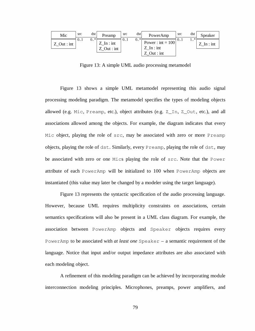
79
PowerAmp
Power : int = 100Z_In : intZ_Out : int
0..1 0..1 0..10..* 0..* 1..*src src src dstdstdst Preamp
Z_In : intZ_Out : int
Speaker
Z_In : int
Mic
Z_Out : int
Figure 13: A simple UML audio processing metamodel
Figure 13 shows a simple UML metamodel representing this audio signal
processing modeling paradigm. The metamodel specifies the types of modeling objects
allowed (e.g. Mic, Preamp, etc.), object attributes (e.g. Z_In, Z_Out, etc.), and all
associations allowed among the objects. For example, the diagram indicates that every
Mic object, playing the role of src, may be associated with zero or more Preamp
objects, playing the role of dst. Similarly, every Preamp, playing the role of dst, may
be associated with zero or one Mics playing the role of src. Note that the Power
attribute of each PowerAmp will be initialized to 100 when PowerAmp objects are
instantiated (this value may later be changed by a modeler using the target language).
Figure 13 represents the syntactic specification of the audio processing language.
However, because UML requires multiplicity constraints on associations, certain
semantics specifications will also be present in a UML class diagram. For example, the
association between PowerAmp objects and Speaker objects requires every
PowerAmp to be associated with at least one Speaker – a semantic requirement of the
language. Notice that input and/or output impedance attributes are also associated with
each modeling object.
A refinement of this modeling paradigm can be achieved by incorporating module
interconnection modeling principles. Microphones, preamps, power amplifiers, and
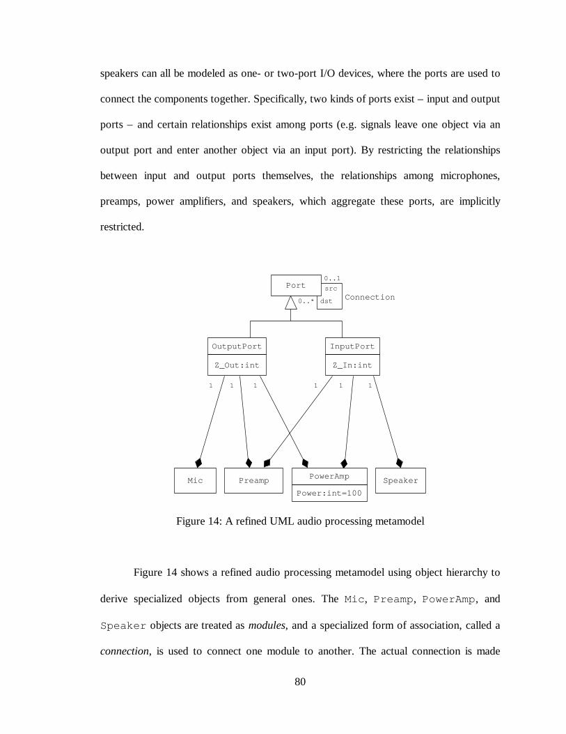
80
speakers can all be modeled as one- or two-port I/O devices, where the ports are used to
connect the components together. Specifically, two kinds of ports exist – input and output
ports – and certain relationships exist among ports (e.g. signals leave one object via an
output port and enter another object via an input port). By restricting the relationships
between input and output ports themselves, the relationships among microphones,
preamps, power amplifiers, and speakers, which aggregate these ports, are implicitly
restricted.
Port
PreampMic PowerAmp
Power:int=100Speaker
1 11 1
0..1
0..*
src
dst
OutputPort
Z_Out:int
InputPort
Z_In:int
Connection
11
Figure 14: A refined UML audio processing metamodel
Figure 14 shows a refined audio processing metamodel using object hierarchy to
derive specialized objects from general ones. The Mic, Preamp, PowerAmp, and
Speaker objects are treated as modules, and a specialized form of association, called a
connection, is used to connect one module to another. The actual connection is made
81
between ports contained in the modules. If directional connections are to be modeled (as
in this example) the ports can be divided into two types – input ports and output ports.
Modules may contain both types of ports, depending on the type of module. For example,
a Mic contains a single OutputPort, while a PowerAmp contains both an
InputPort and an OutputPort.
In Figure 14, the Port acts as a general module interconnection object. A
Connection association, with src and dst roles, is used to associate (i.e. connect)
one Port with another. Notice that Ports are not used as first-class modeling objects in
this paradigm, but are specialized into OutputPort and InputPort objects. Z_Out
and Z_In attributes are associated with OutputPort and InputPort objects,
respectively. The final modeling objects are specified as aggregations of one
OutputPort and/or one InputPort. This approach represents an improvement over
the metamodel of Figure 13 by more clearly defining object containment, derivation and
interconnection, as well as directly associating the impedance attributes with the
OutputPort and InputPort objects.
Static Semantic Specification
While the use of hierarchy allows a modular design approach and makes
composing metamodels easier, such an approach generally requires more constraint
equations to fully constrain the design. For example, the metamodel of Figure 14 allows
full connectivity between any two Port-type objects (e.g. OutputPort or
InputPort objects), regardless of which type of container object they appear in. This
metamodel even allows an OutputPort to connect to itself – a condition that is not
82
permitted in real-world audio processing system, and so should be illegal when modeling
such systems. Also, the simplified metamodel of Figure 13 required that every
PowerAmp object be connected to something. The refined metamodel of Figure 14
contains no such restriction. Therefore, several constraints must be placed on this refined
metamodel.
First, the relationship between OutputPorts and InputPorts must be
limited. OutputPorts may connect to InputPorts and InputPorts may connect
to OutputPorts. No other connections involving OutputPorts and InputPorts
are allowed. The following OCL equation properly constrains this relationship:
Connection->forAll(c |c.src.oclIsTypeOf(OutputPort) and c.dst.oclIsTypeOf(InputPort)) (5)
This expression states that the src role of every Connection association must be
an OutputPort object and the dst role must be an InputPort object.
The interconnections between modules must also be constrained. For example,
Mics can only connect to Preamps, Preamps can only connect to PowerAmps, and
PowerAmps can only connect to Speakers. The following constraint equations specify
these allowed connections:
Mic->forAll(m | m.outputPort.dst->forAll(i | i.preamp)) (6)
Preamp->forAll(p | p.outputPort.dst->forAll(i | i.powerAmp)) (7)
PowerAmp->forAll(a | a.outputPort.dst->forAll(i | i.speaker)) (8)
Equation (6) allows Mics to connect only to Preamps. Note the use of
outputPort (first letter lower case) to refer to the unnamed role at the “Preamp end”
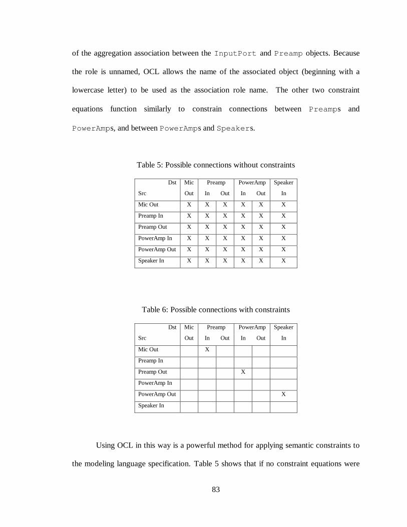
83
of the aggregation association between the InputPort and Preamp objects. Because
the role is unnamed, OCL allows the name of the associated object (beginning with a
lowercase letter) to be used as the association role name. The other two constraint
equations function similarly to constrain connections between Preamps and
PowerAmps, and between PowerAmps and Speakers.
Table 5: Possible connections without constraints
Dst Mic Preamp PowerAmp Speaker
Src Out In Out In Out In
Mic Out X X X X X X
Preamp In X X X X X X
Preamp Out X X X X X X
PowerAmp In X X X X X X
PowerAmp Out X X X X X X
Speaker In X X X X X X
Table 6: Possible connections with constraints
Dst Mic Preamp PowerAmp Speaker
Src Out In Out In Out In
Mic Out X
Preamp In
Preamp Out X
PowerAmp In
PowerAmp Out X
Speaker In
Using OCL in this way is a powerful method for applying semantic constraints to
the modeling language specification. Table 5 shows that if no constraint equations were
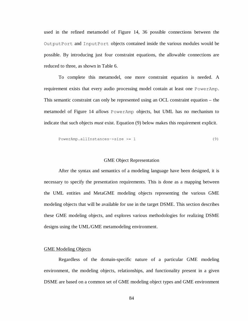
84
used in the refined metamodel of Figure 14, 36 possible connections between the
OutputPort and InputPort objects contained inside the various modules would be
possible. By introducing just four constraint equations, the allowable connections are
reduced to three, as shown in Table 6.
To complete this metamodel, one more constraint equation is needed. A
requirement exists that every audio processing model contain at least one PowerAmp.
This semantic constraint can only be represented using an OCL constraint equation – the
metamodel of Figure 14 allows PowerAmp objects, but UML has no mechanism to
indicate that such objects must exist. Equation (9) below makes this requirement explicit.
PowerAmp.allInstances->size >= 1 (9)
GME Object Representation
After the syntax and semantics of a modeling language have been designed, it is
necessary to specify the presentation requirements. This is done as a mapping between
the UML entities and MetaGME modeling objects representing the various GME
modeling objects that will be available for use in the target DSME. This section describes
these GME modeling objects, and explores various methodologies for realizing DSME
designs using the UML/GME metamodeling environment.
GME Modeling Objects
Regardless of the domain-specific nature of a particular GME modeling
environment, the modeling objects, relationships, and functionality present in a given
DSME are based on a common set of GME modeling object types and GME environment
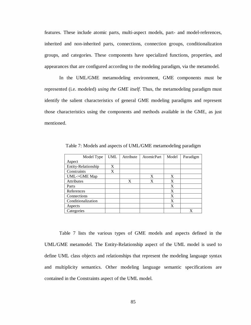
85
features. These include atomic parts, multi-aspect models, part- and model-references,
inherited and non-inherited parts, connections, connection groups, conditionalization
groups, and categories. These components have specialized functions, properties, and
appearances that are configured according to the modeling paradigm, via the metamodel.
In the UML/GME metamodeling environment, GME components must be
represented (i.e. modeled) using the GME itself. Thus, the metamodeling paradigm must
identify the salient characteristics of general GME modeling paradigms and represent
those characteristics using the components and methods available in the GME, as just
mentioned.
Table 7: Models and aspects of UML/GME metamodeling paradigm
Model TypeAspect
UML Attribute AtomicPart Model Paradigm
Entity-Relationship XConstraints XUML->GME Map X XAttributes X X XParts XReferences XConnections XConditionalization XAspects XCategories X
Table 7 lists the various types of GME models and aspects defined in the
UML/GME metamodel. The Entity-Relationship aspect of the UML model is used to
define UML class objects and relationships that represent the modeling language syntax
and multiplicity semantics. Other modeling language semantic specifications are
contained in the Constraints aspect of the UML model.
86
Attribute models are used to model the various types of attributes available in the
GME. These include single- and multi-line textual fields, Boolean toggle values, and
menus. Attribute models may be arranged hierarchically, allowing Attribute models to
contain other Attribute models. Arbitrary levels of Attribute hierarchy are allowed in a
metamodel. Attribute models consist of only one aspect – the Attributes aspect.
AtomicPart models are used to model GME atomic parts. AtomicPart models
have two aspects. The UML->GME Map aspect is used to map a UML object onto a
GME AtomicPart object. Every AtomicPart model must include a reference to a single
UML class object. The Attributes aspect of an AtomicPart model is used to define which
attributes (if any) the modeled atomic part has. Atoms can have an arbitrary number of
attributes associated with them. The Attributes aspect contains one metamodeling
attribute for specifying a bitmap image to represent the atomic part in the target DSME.
The Model model is the most complex GME metamodeling object, having seven
aspects. Before describing these aspects, however, a few comments about models are in
order. GME models contain parts (atomic, model, and reference parts), attributes,
connection groups, and conditionalization groups. However, the model is partitioned
visually according to various aspects associated with the model. The parts contained
within a model can be thought of as members of one (and only one) of these aspects. The
same is true for attributes, connection groups, and conditionalization groups. In the
metamodeling paradigm, parts (models and/or atomic parts) are designated as belonging
to a model by placing a copy of the part into the model's Parts aspect. These parts are
inherited by another aspect of the model – the Aspects aspect – and it is in this aspect that
the metamodeler indicates the desired partitioning. (This is explained in more detail
87
below, and is demonstrated in the Metamodeling Process section.) In a similar manner,
references, connection groups, and conditionalization groups belonging to a particular
model are denoted using the model's References, Connections, and Conditionalization
aspects, respectively, but are partitioned into the model's aspects in the Aspects aspect.
Returning to the seven aspects of a Model model, as was the case with
AtomicPart models, a UML->GME Map aspect is used to associate a UML class object
with a GME Model object. The model's Attributes aspect is used to assign various
attributes to the model. The Parts aspect contains references to GME AtomicPart and
Model models, indicating which parts are contained in the model. Note that to fully
specify a part within a model, both a part name and a part type must be known. The
metamodeling paradigm uses the name of the part reference as the part name and the
name of the UML class object corresponding to the referenced part as the type.
The model's References, Connections, and Conditionalization aspects contain
references to UML class objects. This provides a means for mapping UML associations
onto one of the object relationship mechanisms supported by the GME (e.g. connections,
references, or conditionals). To assign a UML association to a particular kind of GME
relationship, a reference to the association's class object is placed in the appropriate
aspect (e.g. the References, Connections, or Conditionalization aspect) of the model.
During the metamodel interpretation process, group membership is determined by
investigating the UML model to determine which types of objects are associated or
aggregated together to form the group. Once the object types have been determined, the
GME model's Parts aspect is checked for the existence of these types of parts in this
particular model. If parts of the proper type exist, they are used to form the actual
88
members of the relationship group. This is demonstrated in the Metamodeling Process
section.
The Aspects aspect of a Model model is used to partition the model's parts,
references, connection groups, and conditionalization groups into various visualization
aspects of the model. Additionally, the metamodeler may indicate that some or all of the
parts and/or connection groups are inherited across aspects of the model. Inheritance
allows parts and connection groups to appear in more than one aspect of a model.
The final GME model type is the Categories model, which contains a single
Paradigm aspect. GME categories are collections of models. These collections are
modeled by placing references to GME Model models in the Paradigm aspect of a
Categories model, and adding a special Category part, which acts as conditional
controller, to create groups of model references. Each group will result in a named
category being created in the target modeling environment.
Metamodeling Process
This section brings together all the concepts discussed in this chapter and presents
a methodology for designing and creating metamodels using the UML/GME
metamodeling environment. The audio processing system previously discussed is further
expanded in this section and used to demonstrate key concepts of the metamodeling
process.
The expanded audio system contains several new modeling concepts, so new
objects and relationships must be added to enable the creation of valid audio processing
models. The first object to be added is a Person, which represents the analog input to a
microphone. A System object is also added. System objects act as containers for Mic,
89
Preamp, PowerAmp, Speaker, and Person objects (i.e. a System aggregates these
objects). Thus a System becomes a collection of Mics, Preamps, PowerAmps, Speakers,
and Persons.
Another object, a Performer, is added that represents the relationship between a
Person and a Mic. The real-world concept being expressed is that persons using
microphones are referred to as performers. Furthermore, since each performer has
unique audio qualities, preamps are adjusted to tune audio systems for particular
performers. Therefore, a RefToPerformer object is added to represent such an association
between performers and preamps.
One final association must be added that represent the relationship between
microphones and loudspeakers. A microphone represents the source of an electrical
signal reaching the loudspeaker. A UML class object named SoundSource is used to
represent this association.
Figure 15 below shows the UML class diagram design for the expanded audio
processing system. The figure shows the EntityRelationship aspect of the UML-type
model, and includes objects and associations to represent the new modeling concepts just
described.
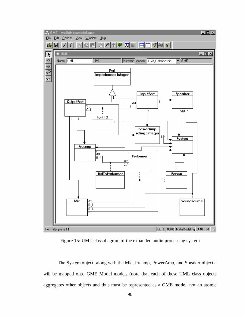
90
Figure 15: UML class diagram of the expanded audio processing system
The System object, along with the Mic, Preamp, PowerAmp, and Speaker objects,
will be mapped onto GME Model models (note that each of these UML class objects
aggregates other objects and thus must be represented as a GME model, not an atomic
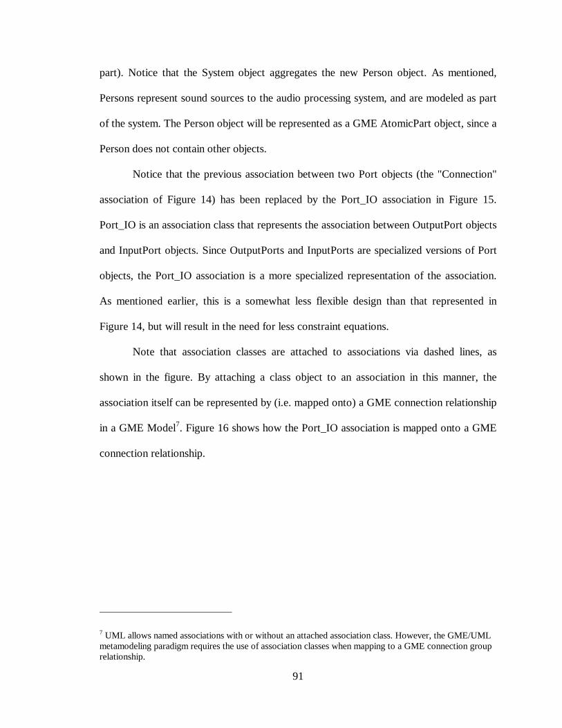
91
part). Notice that the System object aggregates the new Person object. As mentioned,
Persons represent sound sources to the audio processing system, and are modeled as part
of the system. The Person object will be represented as a GME AtomicPart object, since a
Person does not contain other objects.
Notice that the previous association between two Port objects (the "Connection"
association of Figure 14) has been replaced by the Port_IO association in Figure 15.
Port_IO is an association class that represents the association between OutputPort objects
and InputPort objects. Since OutputPorts and InputPorts are specialized versions of Port
objects, the Port_IO association is a more specialized representation of the association.
As mentioned earlier, this is a somewhat less flexible design than that represented in
Figure 14, but will result in the need for less constraint equations.
Note that association classes are attached to associations via dashed lines, as
shown in the figure. By attaching a class object to an association in this manner, the
association itself can be represented by (i.e. mapped onto) a GME connection relationship
in a GME Model7. Figure 16 shows how the Port_IO association is mapped onto a GME
connection relationship.
7 UML allows named associations with or without an attached association class. However, the GME/UMLmetamodeling paradigm requires the use of association classes when mapping to a GME connection grouprelationship.
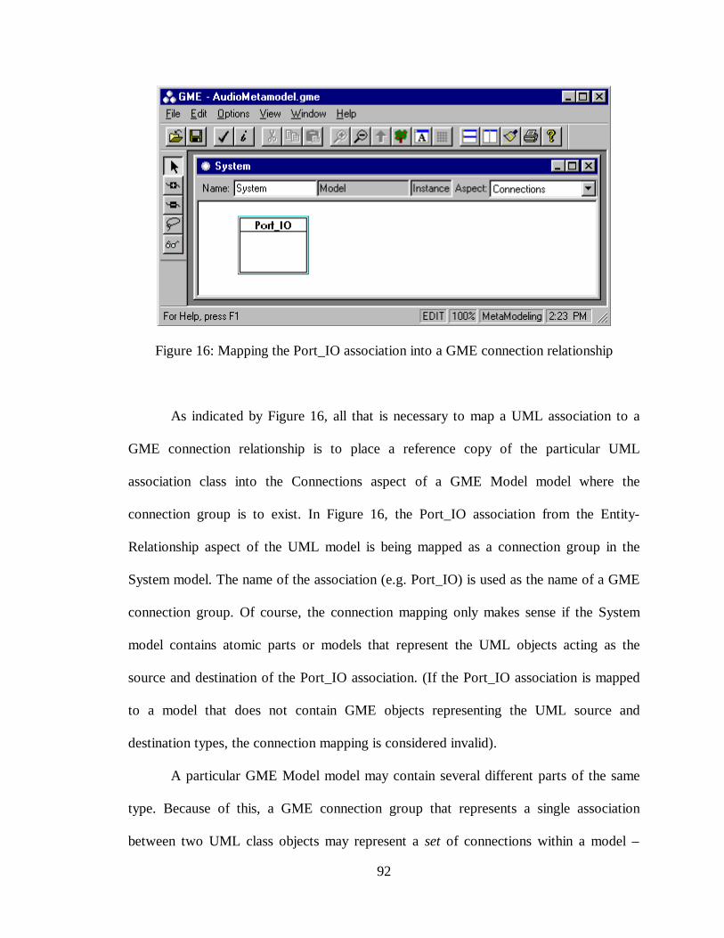
92
Figure 16: Mapping the Port_IO association into a GME connection relationship
As indicated by Figure 16, all that is necessary to map a UML association to a
GME connection relationship is to place a reference copy of the particular UML
association class into the Connections aspect of a GME Model model where the
connection group is to exist. In Figure 16, the Port_IO association from the Entity-
Relationship aspect of the UML model is being mapped as a connection group in the
System model. The name of the association (e.g. Port_IO) is used as the name of a GME
connection group. Of course, the connection mapping only makes sense if the System
model contains atomic parts or models that represent the UML objects acting as the
source and destination of the Port_IO association. (If the Port_IO association is mapped
to a model that does not contain GME objects representing the UML source and
destination types, the connection mapping is considered invalid).
A particular GME Model model may contain several different parts of the same
type. Because of this, a GME connection group that represents a single association
between two UML class objects may represent a set of connections within a model –
93
hence the name connection group. In such cases, the meta-interpreter will resolve all
possible individual connections based on the associated UML types, as explained below.
The simplest case of connection resolution occurs when the associated source and
destination UML class objects both map to GME AtomicPart models (i.e. connections in
the target modeling environment will be between two atomic parts). To resolve all
possible connections, the source and destination UML class objects are located
(OutputPort and InputPort in this example). The names of these UML class objects
represent the types of GME objects involved in the connections, and will be used to
determine which GME atomic parts can participate in a given connection. Once the
source and destination types have been determined, the GME Model model containing
the connection group is located, and each Aspect specification within the model is
analyzed for the presence of at least one pair of source/destination parts of the proper
type. Using the names of the AtomicPart models the UML source and destination class
objects map to, a set of GME connections specifications is created. Note that the number
of connection specifications depends on the number of atomic parts of the proper type
contained in the Model model.
A more complicated case exists when the associated UML objects are aggregated
into other UML objects. (Note that these "other" UML objects will map to GME Model
models and not AtomicPart models). If the GME model containing the connection group
also contains references (discussed below) to parts contained in these "other" GME
Model models, connections must be resolved involving those referenced parts – for all
possible combinations of source and destination parts of the proper type. Thus, a fairly
simple UML connection specification involving aggregated parts can result in a GME
94
connection group that contains many connections involving both atomic and reference
parts (within and without the model containing the connection group). Using the audio
processing system of Figure 15, and assuming a single aspect in the System model, the
Port_IO association mapping shown in Figure 16 results in a GME connection group
containing nine resolved connections, as shown below.
Port_IO { 1 solid line butt } : { aMic Out -> aPreamp In } { aMic Out -> aPowerAmp In } { aMic Out -> aSpeaker In } { aPreamp Out -> aPreamp In } { aPreamp Out -> aPowerAmp In } { aPreamp Out -> aSpeaker In } { aPowerAmp Out -> aPreamp In } { aPowerAmp Out -> aPowerAmp In } { aPowerAmp Out -> aSpeaker In };
Notice that many more connections are generated than allowed by Table 6. This is
because the audio processing system modeling paradigm was designed to allow module
interconnection modeling techniques in the target modeling environment, forcing object
associations to be specified at a higher, more abstract level in the metamodel. The
combination of abstract object association and object aggregation results in a large
number of GME connections, many of which may be illegal. This demonstrates the need
to compliment such generalized modeling concepts with constraint equations such as
equations (6), (7), and (8) and a constraint manager capable of rejecting models that
violate these constraints. If the more abstract Port-to-Port association were used, the
number of resolved connections would grow much larger, requiring many more
constraint equations to restrict the legal connections to those shown in Table 6. However,
if the more specialized associations of Figure 13 are used, no constraint equations would
be required, but the modeler loses the ability to design using module interconnection
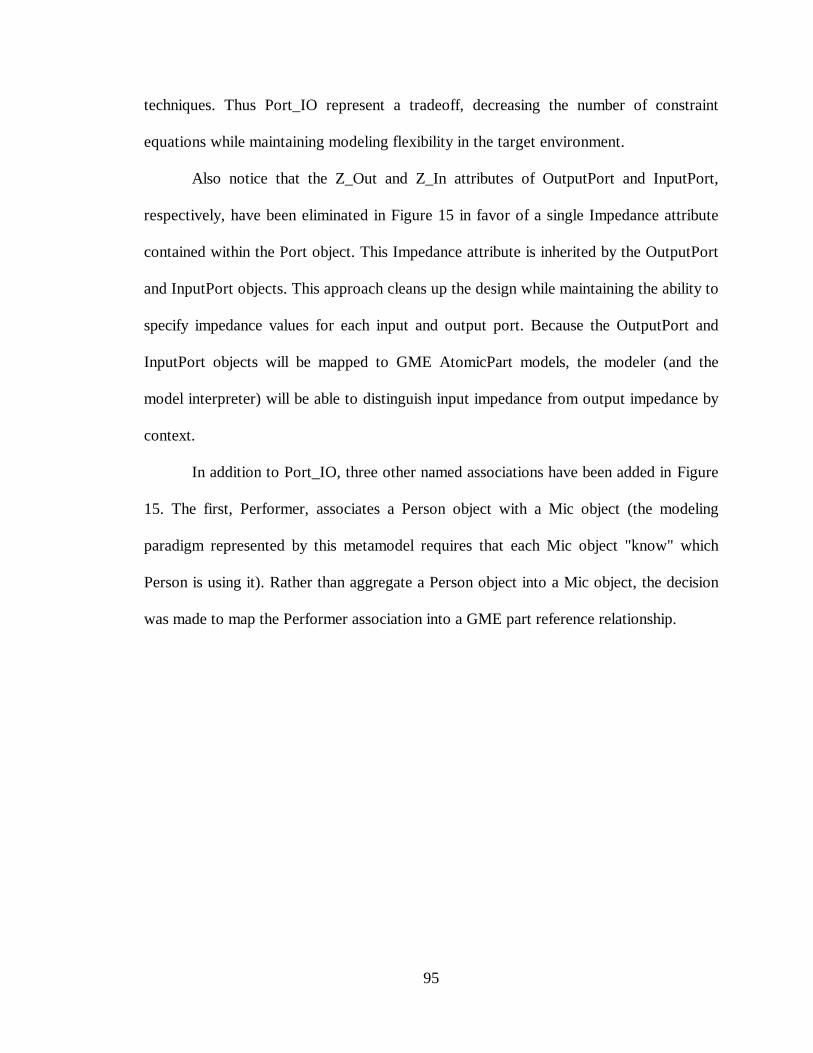
95
techniques. Thus Port_IO represent a tradeoff, decreasing the number of constraint
equations while maintaining modeling flexibility in the target environment.
Also notice that the Z_Out and Z_In attributes of OutputPort and InputPort,
respectively, have been eliminated in Figure 15 in favor of a single Impedance attribute
contained within the Port object. This Impedance attribute is inherited by the OutputPort
and InputPort objects. This approach cleans up the design while maintaining the ability to
specify impedance values for each input and output port. Because the OutputPort and
InputPort objects will be mapped to GME AtomicPart models, the modeler (and the
model interpreter) will be able to distinguish input impedance from output impedance by
context.
In addition to Port_IO, three other named associations have been added in Figure
15. The first, Performer, associates a Person object with a Mic object (the modeling
paradigm represented by this metamodel requires that each Mic object "know" which
Person is using it). Rather than aggregate a Person object into a Mic object, the decision
was made to map the Performer association into a GME part reference relationship.
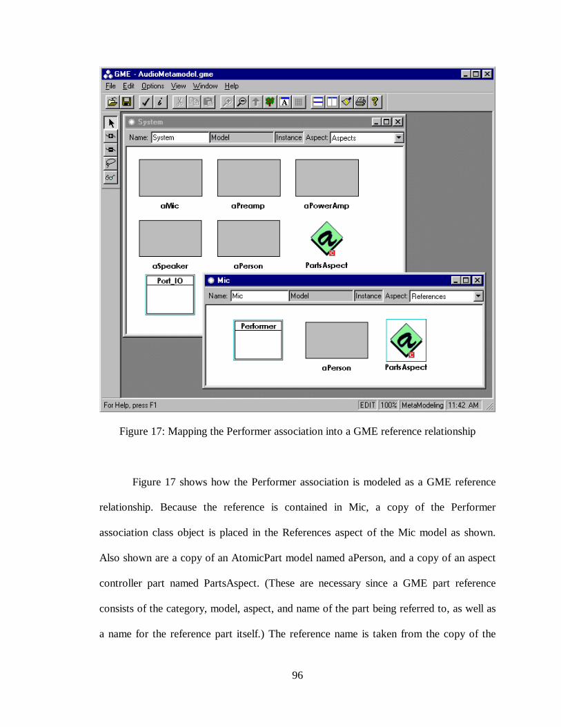
96
Figure 17: Mapping the Performer association into a GME reference relationship
Figure 17 shows how the Performer association is modeled as a GME reference
relationship. Because the reference is contained in Mic, a copy of the Performer
association class object is placed in the References aspect of the Mic model as shown.
Also shown are a copy of an AtomicPart model named aPerson, and a copy of an aspect
controller part named PartsAspect. (These are necessary since a GME part reference
consists of the category, model, aspect, and name of the part being referred to, as well as
a name for the reference part itself.) The reference name is taken from the copy of the
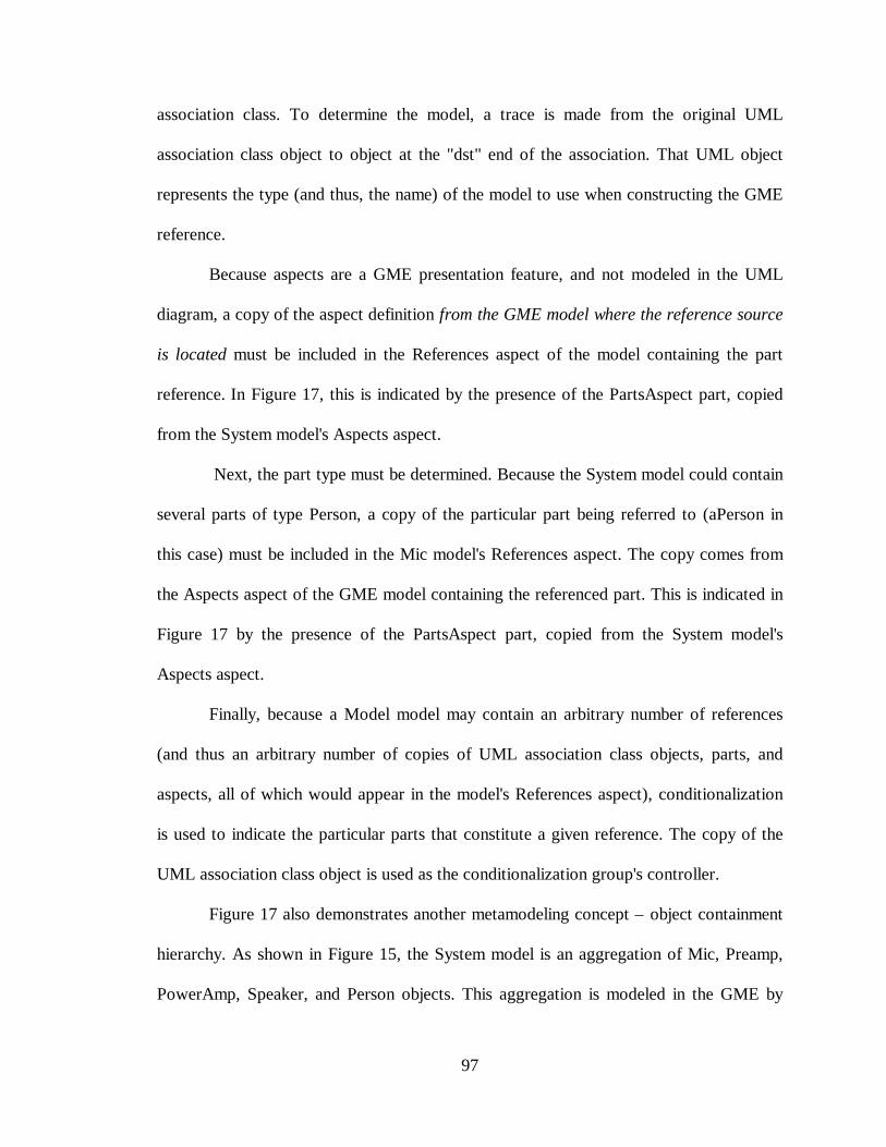
97
association class. To determine the model, a trace is made from the original UML
association class object to object at the "dst" end of the association. That UML object
represents the type (and thus, the name) of the model to use when constructing the GME
reference.
Because aspects are a GME presentation feature, and not modeled in the UML
diagram, a copy of the aspect definition from the GME model where the reference source
is located must be included in the References aspect of the model containing the part
reference. In Figure 17, this is indicated by the presence of the PartsAspect part, copied
from the System model's Aspects aspect.
Next, the part type must be determined. Because the System model could contain
several parts of type Person, a copy of the particular part being referred to (aPerson in
this case) must be included in the Mic model's References aspect. The copy comes from
the Aspects aspect of the GME model containing the referenced part. This is indicated in
Figure 17 by the presence of the PartsAspect part, copied from the System model's
Aspects aspect.
Finally, because a Model model may contain an arbitrary number of references
(and thus an arbitrary number of copies of UML association class objects, parts, and
aspects, all of which would appear in the model's References aspect), conditionalization
is used to indicate the particular parts that constitute a given reference. The copy of the
UML association class object is used as the conditionalization group's controller.
Figure 17 also demonstrates another metamodeling concept – object containment
hierarchy. As shown in Figure 15, the System model is an aggregation of Mic, Preamp,
PowerAmp, Speaker, and Person objects. This aggregation is modeled in the GME by
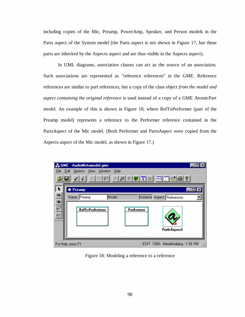
98
including copies of the Mic, Preamp, PowerAmp, Speaker, and Person models in the
Parts aspect of the System model (the Parts aspect is not shown in Figure 17, but these
parts are inherited by the Aspects aspect and are thus visible in the Aspects aspect).
In UML diagrams, association classes can act as the source of an association.
Such associations are represented as "reference references" in the GME. Reference
references are similar to part references, but a copy of the class object from the model and
aspect containing the original reference is used instead of a copy of a GME AtomicPart
model. An example of this is shown in Figure 18, where RefToPerformer (part of the
Preamp model) represents a reference to the Performer reference contained in the
PartsAspect of the Mic model. (Both Performer and PartsAspect were copied from the
Aspects aspect of the Mic model, as shown in Figure 17.)
Figure 18: Modeling a reference to a reference
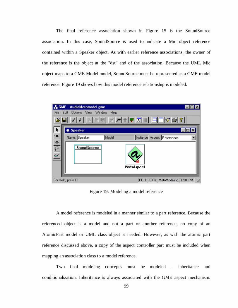
99
The final reference association shown in Figure 15 is the SoundSource
association. In this case, SoundSource is used to indicate a Mic object reference
contained within a Speaker object. As with earlier reference associations, the owner of
the reference is the object at the "dst" end of the association. Because the UML Mic
object maps to a GME Model model, SoundSource must be represented as a GME model
reference. Figure 19 shows how this model reference relationship is modeled.
Figure 19: Modeling a model reference
A model reference is modeled in a manner similar to a part reference. Because the
referenced object is a model and not a part or another reference, no copy of an
AtomicPart model or UML class object is needed. However, as with the atomic part
reference discussed above, a copy of the aspect controller part must be included when
mapping an association class to a model reference.
Two final modeling concepts must be modeled – inheritance and
conditionalization. Inheritance is always associated with the GME aspect mechanism.
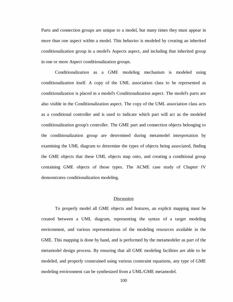
100
Parts and connection groups are unique to a model, but many times they must appear in
more than one aspect within a model. This behavior is modeled by creating an inherited
conditionalization group in a model's Aspects aspect, and including that inherited group
in one or more Aspect conditionalization groups.
Conditionalization as a GME modeling mechanism is modeled using
conditionalization itself. A copy of the UML association class to be represented as
conditionalization is placed in a model's Conditionalization aspect. The model's parts are
also visible in the Conditionalization aspect. The copy of the UML association class acts
as a conditional controller and is used to indicate which part will act as the modeled
conditionalization group's controller. The GME part and connection objects belonging to
the conditionalization group are determined during metamodel interpretation by
examining the UML diagram to determine the types of objects being associated, finding
the GME objects that these UML objects map onto, and creating a conditional group
containing GME objects of those types. The ACME case study of Chapter IV
demonstrates conditionalization modeling.
Discussion
To properly model all GME objects and features, an explicit mapping must be
created between a UML diagram, representing the syntax of a target modeling
environment, and various representations of the modeling resources available in the
GME. This mapping is done by hand, and is performed by the metamodeler as part of the
metamodel design process. By ensuring that all GME modeling facilities are able to be
modeled, and properly constrained using various constraint equations, any type of GME
modeling environment can be synthesized from a UML/GME metamodel.

101
CHAPTER IV
UML/GME METAMODELING ENVIRONMENT
Once a metamodel has been defined and used to synthesize a DMSE, domain
experts can begin modeling specific systems within the domain. While such modeling
activities are quite useful in their own right, the real power of a DSME is realized when
domain models are interpreted using one or more semantic translators. The ability to scan
the domain models, extract various kinds of data, analyze and translate the data, and
synthesize executable models is the central feature of a DSME.
In the case of the UML/GME metamodeling environment, the semantic
translators are used to extract information about the target DSME from the metamodel
and synthesize the configuration files necessary to automatically generate the target
modeling environment. This chapter discusses the UML/GME metamodeling
environment, focusing specifically on the metamodel semantic translation process.
102
ModelingLanguage
Specification
GME Resources
DesignMapping
EDF
MCL
M.I. M.I.
EDF MCL
UML/GME Metamodeling Environment
MetamodelingEnvironment
Configuration Files
DMSE Configuration Files
InterpreterMapping
DSME
Figure 20: DSME generation
Figure 20 illustrates the overall flow of information and the necessary processing
required to specify and generate a target DSME. The metamodeling configuration files
(i.e. the EDF and MCL files shown on the upper left side of the diagram) are used to
generate the UML/GME metamodeling environment. Initially these configuration files
were built by hand, but as explained in Chapter V, Case Studies, a graphical meta-
metamodel has been built using the UML/GME metamodeling environment that can
generate these configuration files automatically.
Once created, the UML/GME metamodeling environment allows a designer to
synthesize a DSME by (1) specifying the desired domain-specific modeling language, (2)
specifying the mappings between the modeling language constructs and the various
modeling services (i.e. resources) available in the GME, and (3) executing the semantic
translators to automatically generate mappings between the metamodel and the target
103
DSME. These mappings take the form of the EDF and MCL configuration files shown
near the bottom of Figure 20. The design mapping process was described in Chapter III.
Here we will concentrate on the interpreter mapping portion of Figure 20.
Remember that the language specification, along with the design mappings,
constitute the actual metamodel. When designing a DSME, once the design mapping
phase is complete, model interpreters are used to synthesize the editor description file
(EDF) and the MCL constraint equations from the metamodel. The DSME EDF and
MCL configuration files are then used to automatically generate and configure the target
DSME. The diagram of Figure 5 has been updated in Figure 21 below to reflect this
modified DSME creation process. Note that when compared to the previous approach,
this new method results in more of the target DSME being generated automatically, as
well as providing features (e.g. constraint management) not previously available in the
MGA.
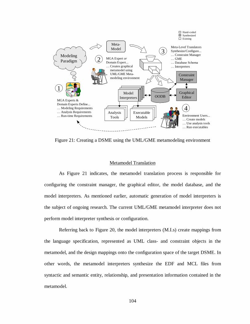
104
MGA Experts &Domain Experts Define...… Modeling Requirements… Analysis Requirements… Run-time Requirements
ModelingParadigm
1
Environment Users...… Create models… Use analysis tools… Run executables
4Analysis
ToolsExecutable
Models
OODBGraphical
Editor
ConstraintManager
MGA Expert orDomain Expert...… Creates graphical metamodel using UML/GME Meta- modeling environment
2
Meta-Model Meta-Level Translators
Synthesize/Configure...… Constraint Manager… GME… Database Schema… Interpreters
3
Hand-codedSynthesizedExisting
ModelInterpreters
Figure 21: Creating a DSME using the UML/GME metamodeling environment
Metamodel Translation
As Figure 21 indicates, the metamodel translation process is responsible for
configuring the constraint manager, the graphical editor, the model database, and the
model interpreters. As mentioned earlier, automatic generation of model interpreters is
the subject of ongoing research. The current UML/GME metamodel interpreter does not
perform model interpreter synthesis or configuration.
Referring back to Figure 20, the model interpreters (M.I.s) create mappings from
the language specification, represented as UML class- and constraint objects in the
metamodel, and the design mappings onto the configuration space of the target DSME. In
other words, the metamodel interpreters synthesize the EDF and MCL files from
syntactic and semantic entity, relationship, and presentation information contained in the
metamodel.
105
Once a particular metamodel has been created, metamodel translation begins with
the creation of data structures corresponding to each UML class- and constraint object, as
well as all GME modeling objects (e.g. atomic parts, models, references, attributes,
connection- and conditionalization groups) and the presentation specifications (e.g. icon
definitions, data structures representing the various aspects of a multi-aspect modeling
paradigm, etc.) Once the data structures are created, they are traversed according to the
associations and connections defined in the metamodel. Additionally, lists containing
references to all atomic parts, model parts, connection groups, and conditionalization
groups contained in each GME model object must be created and associated with each
GME model object. By creating and initializing pointers between the data structures
associated with UML and GME objects, a multigraph is formed that represents the
metamodel specification.
Next, each node of the multigraph is visited, and new container data structures are
created according to the types of objects represented by the nodes and edges of the
multigraph. Data members of these container structures are then initialized using data
from the node and edge objects. Object pointers are added to these container data
structures and initialized to point to the other container structures as dictated by
associations found in the multigraph.
The result of traversing this multigraph and creating a new set of linked container
objects is a second multigraph that also represents the original metamodel, but containing
model data and connection information necessary to efficiently build up the EDF and
MCL files. (Efficiency is emphasized here since the data structures that form this second
multigraph contain no new information – only the organization of that data has been
106
optimized to facilitate a rapid translation into the necessary target DSME configuration
files.) Finally, the second multigraph is traversed and the EDF and MCL files are
synthesized.
It is interesting to note that once metamodel interpretation has been completed,
the newly generated DSME can be invoked while keeping the first metamodeling
environment open. This allows the metamodeler to make changes to the metamodel,
perform a metamodel translation, and immediately see the results of those changes
reflected in the behavior of the generated target DSME.8 This is especially helpful during
the early stages of DSME design, allowing the rapid exploration and testing of alternative
DSME designs and prototypes.
8 Although two or more GME modeling environments may be open at once, changes in the target modelingenvironment will only take effect when the newly generated modeling paradigm is reloaded into the targetGME. This is not the case with the newly generated MCL file, however. The target environment'sconstraint manager responds immediately to changes in the MCL file.
107
CHAPTER V
CASE STUDY
Representational Metamodels
In addition to the audio processing system described in the Metamodeling Process
section of Chapter III, two other domain-specific modeling environments were created
using the UML/GME metamodeling system as part of this research. Together, these
metamodels demonstrate the full range and capability of the UML/GME metamodeling
environment.
ACME
As discussed in Chapter II, ACME [9][10] is an Architectural Description
Language (ADL) used to describe software systems. ACME uses components and
connectors as basic architectural elements, both of which have interconnection interfaces.
Component interfaces are called ports, and connector interfaces are called roles.
Components and connectors are interconnected in a straight forward manner –
component ports attach to connector roles, and connector roles attach to component ports
– to form representations of software architectures. Groups of connections and
components may be grouped together to form attachment groups. ACME use
aggregations of components, connectors, and attachment groups to form systems – larger
and more complex software representations.
ACME is a text-based ADL; no graphical specification for ACME exists.
However, because the ACME metaphor of design is popular and well-known, a graphical

108
representation of the language would be of use to a large community of software system
designers. For this reason, and ACME modeling environment was synthesized from a
UML/GME metamodel. The UML portion from this metamodel is shown in Figure 22.
Figure 22: UML model of the ACME metamodel
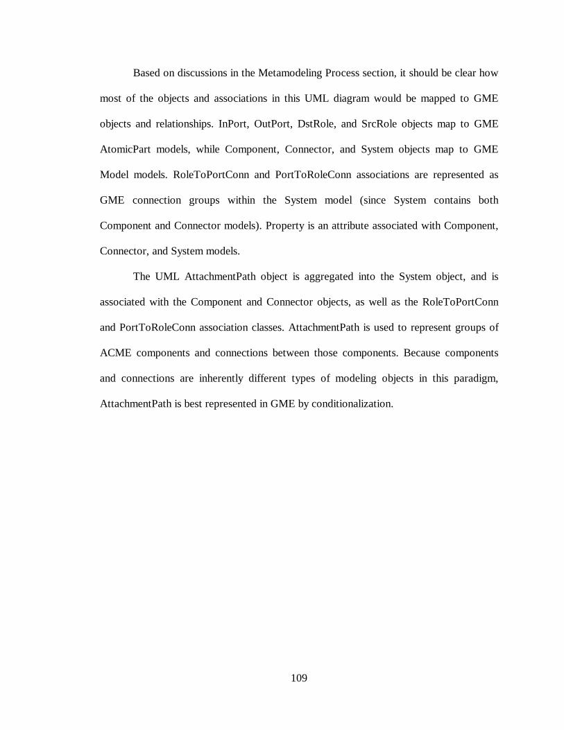
109
Based on discussions in the Metamodeling Process section, it should be clear how
most of the objects and associations in this UML diagram would be mapped to GME
objects and relationships. InPort, OutPort, DstRole, and SrcRole objects map to GME
AtomicPart models, while Component, Connector, and System objects map to GME
Model models. RoleToPortConn and PortToRoleConn associations are represented as
GME connection groups within the System model (since System contains both
Component and Connector models). Property is an attribute associated with Component,
Connector, and System models.
The UML AttachmentPath object is aggregated into the System object, and is
associated with the Component and Connector objects, as well as the RoleToPortConn
and PortToRoleConn association classes. AttachmentPath is used to represent groups of
ACME components and connections between those components. Because components
and connections are inherently different types of modeling objects in this paradigm,
AttachmentPath is best represented in GME by conditionalization.
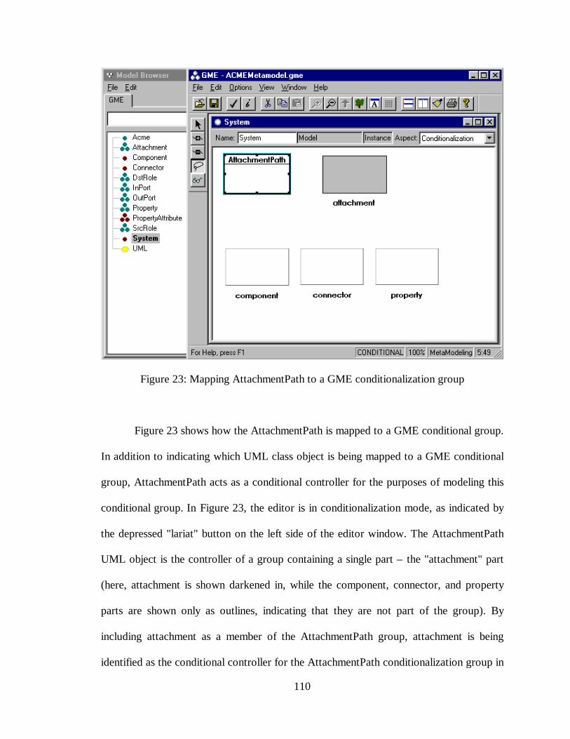
110
Figure 23: Mapping AttachmentPath to a GME conditionalization group
Figure 23 shows how the AttachmentPath is mapped to a GME conditional group.
In addition to indicating which UML class object is being mapped to a GME conditional
group, AttachmentPath acts as a conditional controller for the purposes of modeling this
conditional group. In Figure 23, the editor is in conditionalization mode, as indicated by
the depressed "lariat" button on the left side of the editor window. The AttachmentPath
UML object is the controller of a group containing a single part – the "attachment" part
(here, attachment is shown darkened in, while the component, connector, and property
parts are shown only as outlines, indicating that they are not part of the group). By
including attachment as a member of the AttachmentPath group, attachment is being
identified as the conditional controller for the AttachmentPath conditionalization group in
111
the target environment. Note that no UML class object maps to this "attachment" part.
Instead, a new GME AtomicPart model was created specifically as a controller part. This
is necessary since conditionalization is a presentation mechanism unique to the GME –
the UML diagram does not, and should not, contain "extra" objects only for use as
presentation aids. Of course, any of the other parts contained in the System model (e.g. a
component, a connector, or a property part) could have been selected as the conditional
controller for the AttachmentPath conditional group.
Several semantic constraints are associated with this ACME modeling
environment. Some, such as the multiplicity requirements on associations, are explicitly
shown in the UML diagram of any metamodel. For example, Figure 22 indicates that a
Component-type object must contain one InPort-type object and one OutPort-type object.
Because the GME can only allow or disallow hierarchical "part-of" membership (i.e.
parts are either allowed or not allowed to be contained within models), one or more
constraints are necessary to ensure that the proper number of child parts are included in
parent parts. Such constraints can be synthesized from the metamodel by the metamodel
interpreter. In the case of Figure 22, the following constraint was synthesized to control
the number of InPort objects that must be included in Component objects. Note that the
metamodel interpreter synthesizes a similar constraint for every UML aggregation.
on demand_eventconstraint SynthesizedConstraint0()priority=0"Every Component-type object must contain exactly 1 InPort-typeobject(s)" { models("Component")->forAll(model | (model.parts()->select(p |p.kindOf()="InPort")->size() = 1))}
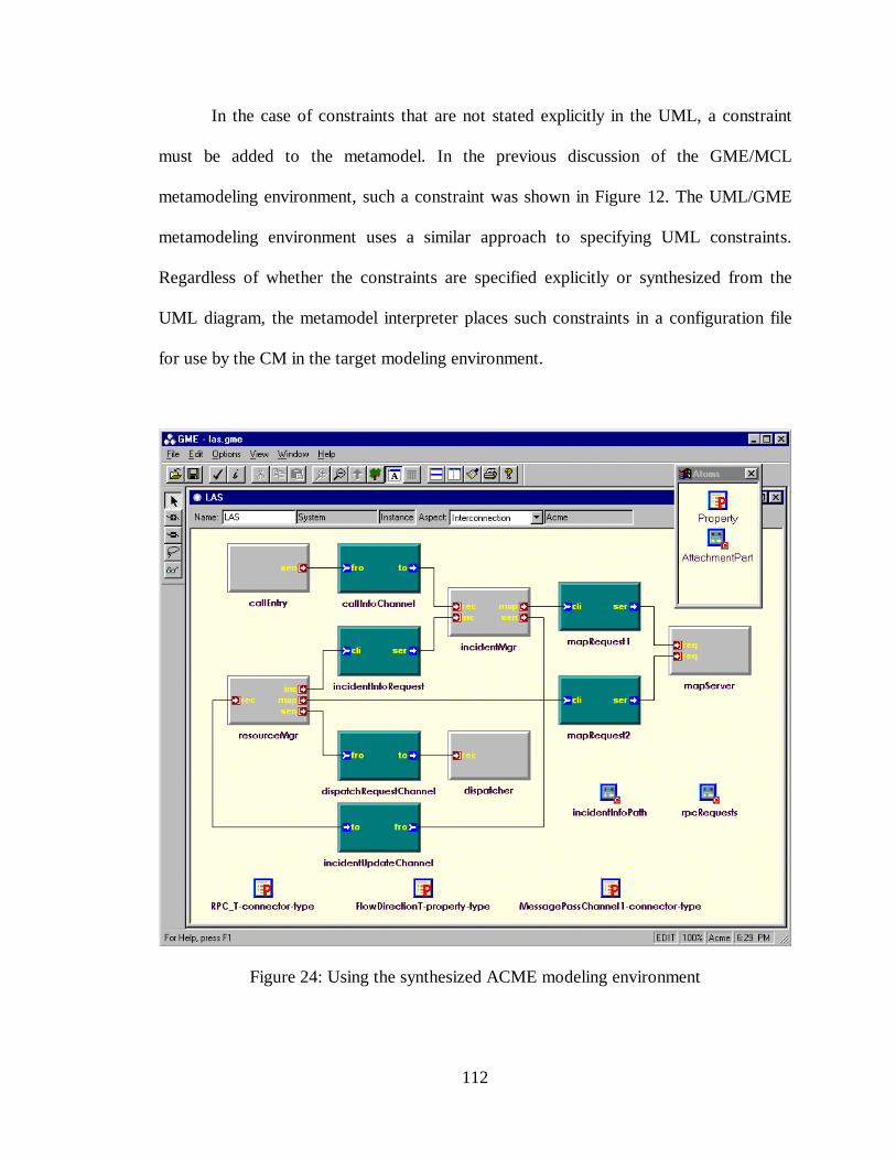
112
In the case of constraints that are not stated explicitly in the UML, a constraint
must be added to the metamodel. In the previous discussion of the GME/MCL
metamodeling environment, such a constraint was shown in Figure 12. The UML/GME
metamodeling environment uses a similar approach to specifying UML constraints.
Regardless of whether the constraints are specified explicitly or synthesized from the
UML diagram, the metamodel interpreter places such constraints in a configuration file
for use by the CM in the target modeling environment.
Figure 24: Using the synthesized ACME modeling environment
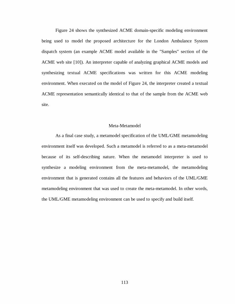
113
Figure 24 shows the synthesized ACME domain-specific modeling environment
being used to model the proposed architecture for the London Ambulance System
dispatch system (an example ACME model available in the "Samples" section of the
ACME web site [10]). An interpreter capable of analyzing graphical ACME models and
synthesizing textual ACME specifications was written for this ACME modeling
environment. When executed on the model of Figure 24, the interpreter created a textual
ACME representation semantically identical to that of the sample from the ACME web
site.
Meta-Metamodel
As a final case study, a metamodel specification of the UML/GME metamodeling
environment itself was developed. Such a metamodel is referred to as a meta-metamodel
because of its self-describing nature. When the metamodel interpreter is used to
synthesize a modeling environment from the meta-metamodel, the metamodeling
environment that is generated contains all the features and behaviors of the UML/GME
metamodeling environment that was used to create the meta-metamodel. In other words,
the UML/GME metamodeling environment can be used to specify and build itself.
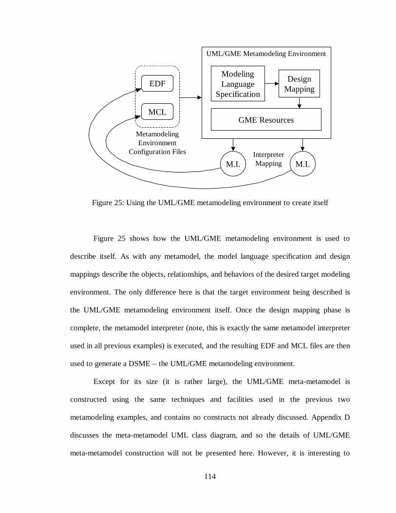
114
ModelingLanguage
Specification
GME Resources
DesignMapping
EDF
MCL
M.I. M.I.
UML/GME Metamodeling Environment
MetamodelingEnvironment
Configuration Files InterpreterMapping
Figure 25: Using the UML/GME metamodeling environment to create itself
Figure 25 shows how the UML/GME metamodeling environment is used to
describe itself. As with any metamodel, the model language specification and design
mappings describe the objects, relationships, and behaviors of the desired target modeling
environment. The only difference here is that the target environment being described is
the UML/GME metamodeling environment itself. Once the design mapping phase is
complete, the metamodel interpreter (note, this is exactly the same metamodel interpreter
used in all previous examples) is executed, and the resulting EDF and MCL files are then
used to generate a DSME – the UML/GME metamodeling environment.
Except for its size (it is rather large), the UML/GME meta-metamodel is
constructed using the same techniques and facilities used in the previous two
metamodeling examples, and contains no constructs not already discussed. Appendix D
discusses the meta-metamodel UML class diagram, and so the details of UML/GME
meta-metamodel construction will not be presented here. However, it is interesting to
115
compare the semantics of the UML modeling portion of the UML/GME meta-metamodel
with the UML meta-metamodel presented in the UML Semantics document [3].
UML/GME Meta-Metamodel and UML Meta-Metamodel Comparison
UML contains many modeling features not used in the UML/GME metamodeling
environment, such as state chart modeling, collaborations, use cases, etc., as well as many
functions and operations on allowed modeling objects. However, the UML meta-
metamodel defines a core set of object modeling features, many of which are used by the
UML/GME metamodeling environment. To ensure compatibility with the UML standard,
the UML modeling portion of the UML/GME metamodeling environment must have the
same syntax and semantics as that found in a similar subset of UML.
Syntactic Comparison
Figure 26 shows the portion of the UML/GME meta-metamodel used to define
the UML modeling objects and associations used in the UML/GME metamodeling
environment. Direct comparison of this meta-metamodel with a suitably trimmed down
portion the UML meta-metamodel reveals that both meta-metamodels define similar sets
of core UML modeling objects.9 Differences center around the need for a separate
Aggregation association in the UML/GME meta-metamodel, due primarily to a lack of
support for first-class association ends in the GME. Also, because the GME does not
support attaching connections directly to other connections, a feature which is needed to
9 Due to the size and complexity of UML, this comparison was performed using an appropriate subset ofthe UML meta-metamodel. Object hierarchy was flattened where possible, out-of-scope objects wereomitted, and class object attributes were ignored.
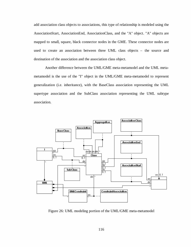
116
add association class objects to associations, this type of relationship is modeled using the
AssociationStart, AssociationEnd, AssociationClass, and the "A" object. "A" objects are
mapped to small, square, black connector nodes in the GME. These connector nodes are
used to create an association between three UML class objects – the source and
destination of the association and the association class object.
Another difference between the UML/GME meta-metamodel and the UML meta-
metamodel is the use of the "I" object in the UML/GME meta-metamodel to represent
generalization (i.e. inheritance), with the BaseClass association representing the UML
supertype association and the SubClass association representing the UML subtype
association.
Figure 26: UML modeling portion of the UML/GME meta-metamodel
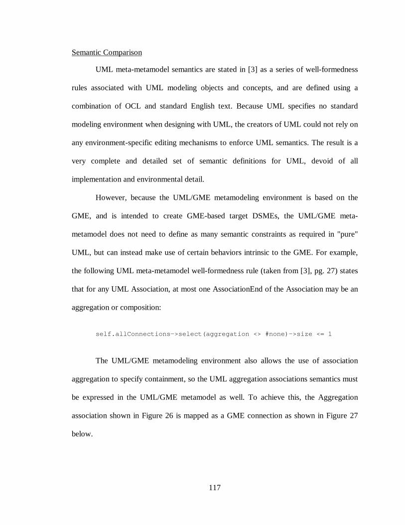
117
Semantic Comparison
UML meta-metamodel semantics are stated in [3] as a series of well-formedness
rules associated with UML modeling objects and concepts, and are defined using a
combination of OCL and standard English text. Because UML specifies no standard
modeling environment when designing with UML, the creators of UML could not rely on
any environment-specific editing mechanisms to enforce UML semantics. The result is a
very complete and detailed set of semantic definitions for UML, devoid of all
implementation and environmental detail.
However, because the UML/GME metamodeling environment is based on the
GME, and is intended to create GME-based target DSMEs, the UML/GME meta-
metamodel does not need to define as many semantic constraints as required in "pure"
UML, but can instead make use of certain behaviors intrinsic to the GME. For example,
the following UML meta-metamodel well-formedness rule (taken from [3], pg. 27) states
that for any UML Association, at most one AssociationEnd of the Association may be an
aggregation or composition:
self.allConnections->select(aggregation <> #none)->size <= 1
The UML/GME metamodeling environment also allows the use of association
aggregation to specify containment, so the UML aggregation associations semantics must
be expressed in the UML/GME metamodel as well. To achieve this, the Aggregation
association shown in Figure 26 is mapped as a GME connection as shown in Figure 27
below.
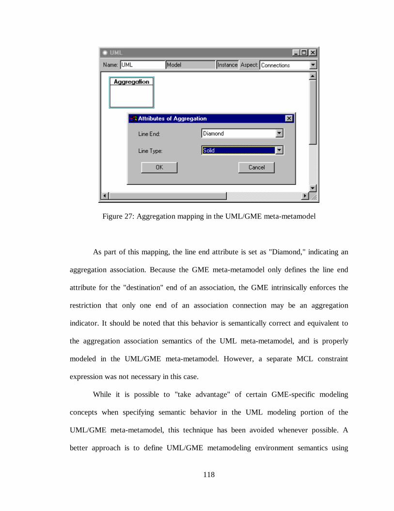
118
Figure 27: Aggregation mapping in the UML/GME meta-metamodel
As part of this mapping, the line end attribute is set as "Diamond," indicating an
aggregation association. Because the GME meta-metamodel only defines the line end
attribute for the "destination" end of an association, the GME intrinsically enforces the
restriction that only one end of an association connection may be an aggregation
indicator. It should be noted that this behavior is semantically correct and equivalent to
the aggregation association semantics of the UML meta-metamodel, and is properly
modeled in the UML/GME meta-metamodel. However, a separate MCL constraint
expression was not necessary in this case.
While it is possible to "take advantage" of certain GME-specific modeling
concepts when specifying semantic behavior in the UML modeling portion of the
UML/GME meta-metamodel, this technique has been avoided whenever possible. A
better approach is to define UML/GME metamodeling environment semantics using
119
MCL-based well-formedness rules similar to those found in UML whenever possible,
relying on the GME constraint manager to verify the stated constraints. This approach
provides a clearer separation of UML/GME metamodeling semantics in the meta-
metamodel, and provides maximum design freedom and flexibility for the GME as it
evolves over time (i.e. features will not have to be incorporated into the GME merely to
support specific meta-metamodeling techniques).
This approach also allows many of the UML meta-metamodel well-formedness
rules to be used directly to specify the UML modeling semantics of the UML/GME
metamodeling environment, and still others to be used with only slight modification.
However, because the GME inherently restricts how some modeling concepts are
presented to the user, additional MCL constraints must be formulated to properly
constrain any "alternative" notations used in the UML/GME meta-metamodel (such as
the "A" objects of Figure 26) while maintaining a semantics consistent with the UML
meta-metamodel.
To illustrate this, a total of fifteen constraint rules are necessary to properly define
the UML object modeling semantics used in the UML/GME metamodeling environment.
Of these fifteen, nine can be derived directly from the UML well-formedness rules in [3],
three are inherently specified as part of the design mapping between UML and GME
modeling objects within the UML/GME meta-metamodel, and three "new" MCL
constraints are needed to support the alternative notation discussed above.
120
CHAPTER VI
RESULTS AND FUTURE WORK
Analysis of the UML/GME Metamodeling Environment
The UML/GME metamodeling environment allows the specification and
synthesis of any GME-based target modeling environment. By properly separating
modeling language syntax, semantics, and presentation requirements, the cognitive
process of metamodel design is enhanced without unduly constraining the metamodeler.
Users of this system have reported that the metamodeling paradigm is intuitive and easy
to work with, being much less prone to error than previous text-based approaches to
modeling environment specification and design. Also, because the UML/GME
metamodeling environment has at its center the UML-based description of the target
environment's objects and relationships, metamodelers were able to retain a consistent
picture of the overall modeling environment being designed while concentrating on
specific low-level language representation and modeling details. These observations are
derived from exit interviews conducted with users of the system.
Novice metamodelers who had used the earlier OMT/GME-based metamodeling
system reported that the UML/GME metamodeling environment was more intuitive and
better suited to the design of DSMEs than the OMT/GME-based system. They noted that
this was especially evident during the early phases of DSME design.
121
Capabilities
Because more and more computer- and software engineers are using UML to
model computer based systems and languages, the use of UML in the UML/GME
metamodeling environment enables the target modeling environment user to participate
more fully in the DSME design process. Potential users familiar with UML but relatively
new to the GME were able, with only a minimum of training, to specify DSME
requirements using the UML/GME metamodeling environment. Of course, before being
able to specify a complete metamodel, they needed to learn what types of resources were
available in the GME, and had to become familiar with the graphical idioms used to
specify the mapping between the UML and the GME modeling constructs.
While the text-based EDF does not allow hierarchical nesting of part- and aspect
attributes, UML/GME metamodels do allow hierarchical aspect specifications (these are
"flattened" by the metamodel interpreter during the EDF synthesis process). Also, part-
to-part associations may be specified outside of a particular model's context – if either of
the associated parts are contained in a model, all GME-mapped connections resulting
from those part-to-part associations are synthesized hierarchically by the metamodel
interpreter. Again, this amounts to a "flattening" of the design hierarchy.
As discussed earlier, the UML/GME metamodeling environment is self-
describing, and can be used to model all modeling capabilities of the GME. Although still
in the early stages of development, many DSMEs have been specified and synthesized
using the UML/GME metamodeling environment.
The most significant improvement over other UML-based modeling systems is
the ability to attach syntactic and semantic meaning to the metamodels, and to apply
semantic translators (i.e. interpreters) to the metamodels, allowing automatic synthesis of
122
DSME's from the metamodels. And although synthesis of the semantic translators has not
yet been realized, current research indicates this is both feasible and possible.
Regarding the use of UML and the OCL-based MCL constraint language to
define the target modeling language syntax and semantics, it should be noted that the goal
in developing the UML/GME metamodeling environment was not to duplicate all
features of UML, nor to adhere to a strict realization of all UML object modeling syntax.
Rather, this research sought to provide techniques and methods for DSME designers
familiar with UML semantics to allow quick and accurate specification of modeling
languages and DSMEs. Clearly that goal has been met.
Limitations and Restrictions
Although this research has led to several advances in DSME specification and
synthesis capabilities, limitations still exist. Some of the more important limitation are
addressed here.
The UML/GME metamodeling environment does not use UML class attribute
information, but requires the metamodeler to create GME-based attribute specifications
for inclusion in target modeling objects. This is due, in part, to the fact that UML class
attributes are merely text strings, not as first-class modeling objects in the UML model.
Consequently, UML class attributes are not inherited as specialized UML class objects
are derived from more general ones.
As mentioned in the Capabilities section, part-to-part connections can be properly
synthesized from UML containment specifications. However, currently only one level of
connection inheritance hierarchy is supported. For example, if typeA parts can be
connected to typeB parts, and one or more typeA parts are contained in a typeM model,
123
all possible connections between the typeA parts inside the typeM model and typeB parts
located outside the typeM model will be synthesized by the metamodel interpreter.
However, if a typeX model contains the typeM model, no connections will be
synthesized from typeA parts contained inside the typeM model to any typeB parts that
exist outside of the typeX model. What is needed is the ability for the interpreter to
synthesize proper GME connections between parts separated by any level of object
hierarchy, since many modeling paradigms require connections between parts located at
various levels of hierarchy.
Another limitation relates to model size in the UML/GME metamodeling
environment. As models grow large, the Windows-based GME editor creates "scrolling
windows" that allow the metamodeler to view a model space larger than the screen. The
GME attempts to mitigate this through a "zoom in/zoom out" mechanism. However,
when zooming out, detail is lost as the individual models "shrink" in size to fit within the
screen display. This limitation is compounded by the fact the UML is inherently a two-
dimensional graphical notation, and no recommended method exists for organizing UML
diagrams into groups of sub-diagrams. Metamodelers need larger and larger screens to
see the overall design in detail. Although the separation of syntactic, semantic, and
presentation requirements within the metamodel tends to partition the metamodel into
smaller and more manageable pieces, the problem still exists. (One solution is discussed
in the next section).
Finally, although a metamodeler can have both the metamodeling environment
and the target modeling environment active at the same time, only the newly generated
constraints are immediately available for use by the target DSME. A newly generated
124
modeling paradigm must be reloaded in the target DSME before the changes take effect.
Changing the modeling paradigm in this way can result in invalid and/or unusable
models. Currently no effective strategy exists for migrating models across modeling
paradigms.
Recommendations for Future UML/GME Metamodeling Research
The research conducted as part of this dissertation only begins to explore the
possibilities for DSME design and generation. As mentioned earlier, research is being
conducted to add interpreter synthesis capabilities to the UML/GME metamodeling
environment. Recommendations for additional research are made below.
MCL Expression "Helper"
MCL expressions are either synthesized automatically from the metamodel UML
diagram, as in the case of connection multiplicity constraints, or they are explicitly
supplied by the metamodeler. When stating constraints explicitly, the metamodeler
provides the MCL expression as a simple text string. This is both time consuming and
error prone, especially if some of the objects being referred to in the constraint are hidden
in unopened models or are contained in aspects not currently visible to the metamodeler.
Also, no syntax checking is performed during expression creation, and the environment
provides no aid in constructing the constraint.
What is needed is some sort of automated helper – such as a Windows-based
"Wizard" object – to guide the metamodeler during the creation of MCL expressions. The
wizard should provide automatic or semi-automatic keyword recognition and/or
selection, as well as real-time syntax checking.
125
Additional MCL Operations
This research has revealed the need for a more complete set of MCL operations
and functions. A full set of end-to-end part connection functions are needed to simplify
the specification of certain types of connections involving contained and inherited parts.
Also, a function similar to the OCL "allSuperTypes" is needed to give access to an
object’s ancestors – necessary in order to properly guard against circular references.
Additional Constraint Synthesis
This research has demonstrated the ability to automatically synthesize MCL
constraints from the UML/GME metamodel. Further research should be conducted on
constraints common to all GME-based metamodeling environments to allow libraries of
common constraints to be used to rapidly specify certain types of modeling environment
behavior. Also, end-user should be able to define edit-time constraints – ad hoc
constraints applied directly to the DSME by the modeler, not the metamodeler.
Model/Atomic Part Synthesis
Currently, some redundancy exists between the UML and GME sides of the
metamodel. Class objects that aggregate other class objects and associations will clearly
be mapped to GME Model models (since AtomicPart models cannot contain any objects).
Similarly, UML class objects that are not used to aggregate other objects are likely to be
mapped to GME AtomicPart models. However, creating the target GME Model- and
AtomicPart objects, as well as specifying the UML-to-GME mapping, is done by hand,
and as GME Model models are created, references to the AtomicPart models contained
126
within them must be explicitly placed inside the Model models – even though this
containment has already been specified in the UML diagram. Mechanisms should be
developed for automatic creation of contained part objects, and for establishing the
necessary UML-to-GME mapping for these automatically created parts and models.
Similar redundancy exists in the case of references and conditionalization.
UML Diagram Partitioning
As previously discussed, large UML diagrams can be difficult to manipulate and
use in the UML/GME metamodeling environment. The UML/GME metamodeling
paradigm should be extended to allow the UML diagram to be partitioned across multiple
UML Model models. Any class object appearing in more than one of these UML Model
models would be treated as the same object, regardless of where or how often it appears,
allowing "layers" of UML sub-diagrams to be created. This layering of the UML diagram
would allow the metamodeler to design and view relevant portions of the UML diagram
without presenting him/her with unnecessary or out-of-scope information. This could also
be used with the UML "design libraries" suggested earlier.
127
Appendix A
MODELING
This appendix is presented to familiarize readers with the terms and concepts that
surround any discussion of metamodeling, and to ensure a proper context for a discussion
of modeling in general. Many modeling terms and concepts are discussed, including
modeling, modeling languages, model-integrated computing, and model-integrated
program synthesis. All literature references in this Appendix are listed in the References
section of the dissertation.
Modeling Languages
Modeling is the process of creating an abstract representation of an engineering
system, and as such, modeling becomes a key strategy in the engineering design process.
The artifacts of the modeling process are models – abstractions of the original system. As
noted by Rumbaugh et al. [21], models serve several useful purposes:
• Testing a physical entity before building it
• Communicating with customers
• Visualization
• Reduction of complexity
While all of these purposes are important, perhaps the most important feature of a
model is its ability to reduce the complexity of a design. Such abstraction enables a
128
clearer understanding of vital design elements and their relationships to each other, while
allowing a designer to readily see how each element contributes to the overall design.
Designing today's large software and hardware systems would be impossible without the
ability to create and analyze models.
To aid designers in creating models of hardware and software systems, various
modeling languages and systems have been created. For such modeling systems to be
successful, they must be specific enough to allow designers to represent the key elements
of various designs, without unduly constraining the designer, and yet remain general
enough to allow a fairly wide variety of models to be created. Of course, some modeling
languages are more suited to the task of hardware and software modeling that others.
Some languages, such as ACME and C2, are oriented toward modeling software
architectures, while others, such as Very High Speed Integrated Circuit (VHSIC)
Hardware Description Language (VHDL), are more hardware oriented. Some modeling
languages, such as the Unified Modeling Language (UML), seek to provide capabilities
for modeling more complex systems that include both hardware and software. However,
there can never be one, universal design language, since different designers, working in
different domains, require design tools tailored to the domain at hand.
Before investing the time and effort required to exploit a modeling language, the
language must be recognized as a standard, if not within the entire computer systems
design community, then at least within the particular design domain of interest. Modeling
languages that are considered standards (the term "standard" is used somewhat loosely
here, since this is a relatively new field and new modeling languages are constantly being
developed) have the ability to model entities, behaviors, and relationships in a number of
129
ways – usually driven by existing practice within a given discipline. For example, Harel's
Statecharts [37][38] are a well known, often used method for describing the dynamic,
interactive behavior of systems and subsystems. UML supports the use of statecharts (as
well as other methods) for describing dynamic system behavior.
Another important aspect of modeling languages is the ability to adequately
express common modeling concepts. Certain design requirements exist in many
engineering disciplines, such as the need to represent the components in a system
hierarchically, the need to associate certain objects with other objects (including the
multiplicity of such associations), and the need to represent various relationships among
objects. Similarly, a modeling language should support design component reuse. The use
of standard templates and/or libraries of standard, parameterized design components
representing these common modeling concepts ensures efficient and consistent models
while minimizing design time.
Another desirable modeling language feature is multi-aspect modeling. Multi-
aspect modeling refers to the ability to view a common, unified set of models from
different perspectives or aspects. Subsystem designers need the ability to "filter out" parts
of the overall system design that do not pertain directly to their subsystem, but to ensure
that any interaction between subsystems is maintained when viewing the system as a
whole. For example, consider a fly-by-wire flight control system. The system can be
modeled using a unified model (perhaps a database) that contains all design information.
However, portions of that unified model may be presented to subsystem designers in
three distinct aspects – the hardware aspect, consisting of models representing the
electrical and mechanical components of the flight control system; the software
130
architecture aspect, containing models of the various data structures and message passing
facilities; and the control-law algorithm aspect, where the system's control feedback
functions are modeled, possibly using math models. Each of these aspects may be
considered separately when designing, analyzing and testing the system's various
subsystems, but must be unified when performing analysis and testing the overall system
model.
Coupled with the need for standardized modeling languages and language
component reuse is the need for tools to support these languages. Designers must be able
to rapidly prototype designs, refine and enhance their designs, integrate those designs
with other design and analysis tools, and evolve their designs over time. A design
environment can provide the designer with proper amounts of feedback regarding the use
of the language, apply constraints prohibiting the designer from creating invalid models,
and provide various mechanisms for using the models in support of larger design goals
(e.g. simulation or safety analysis). Languages that are not supported by some sort of
design infrastructure or design environment tend not to be very useful, and have little
chance of being accepted as standards by the design community.
Once models have been created, the modeler must ensure that the models
accurately reflect reality. This means the models must be both valid for the domain and
correct in their representation of the key abstractions of the particular system they
represent. Ensuring correctness is often a matter of inspection and testing. There is no
easy formula that can be applied to a model to guarantee correctness. However, validity –
the state of being a legal model that obeys the type and construction rules of the domain –
is somewhat easier to check. One method is to use formal methods when creating the
131
models. Today, many formal languages exist that can be used to create models of
domain-specific systems. Usually, these models take the form of formal axioms – often
written in some form of predicate calculus – that describe key behaviors or relationships
of entities in the models. Then, various theorems are created that also describe certain
behaviors and relationships believed to be true. Finally, the modeler attempts to prove the
validity of the theorems in terms of the axioms. Usually such proof strategies are
performed using automated or semi-automated proof checkers. If the modeler has
developed sound axioms and theorems, a formal proof gives a high degree of confidence
in the model's validity. Two major drawbacks when using formal methods are (1) the
need for highly specialized training in the use of formal methods, and (2) the lack of
formal methods tools that can be easily integrated into a MIPS environment.
As mentioned above, many design scenarios can benefit from a simulation
capability, if the particular modeling language being used can support such simulation
activities. By allowing the modeler to simulate various static and dynamic conditions in
the models, the designer can get a much better picture of the system's expected behavior,
allowing designs to be analyzed, compared, and refined. These activities can range from a
simple model translation capability, whereby models are transformed from one form to
another more suitable for use by existing simulation tools, to a completely integrated
simulation environment that allows the designer to design, analyze, and simulate various
designs from within one integrated environment. Such integrated design and simulation
environments provide more immediate feedback to the designer, allowing rapid model
development and analysis, but can cause the design environment to be rather intolerant of
changes in the modeling language itself.
132
Modeling has long been recognized as having many benefits. Simply performing
the act of modeling often results in a more complete understanding of the system by its
designers. This can be considered a passive form of knowledge acquisition on the part of
the designer – more is known about the system as a result of the modeling process itself.
Such gains in understanding are useful and not to be discounted. However, many times
the designer creates models specifically to operate on them in some way, performing
some sort of "what if" analysis, assigning an operational semantics to the models, or, in
the case of executable models, incorporating execution semantics into the models. For
example, if a designer is able to include execution semantics in the models of a
production monitoring system in a manufacturing plant, the models could be used to
control the production monitoring computers located on the manufacturing floor inside
the plant.
One of the most important criteria in a modeling language is the ability to use the
language to model itself. Changes to the modeling language will drive changes to any
supporting design environment. If the modeling language has support for a meta-
language, the language can be used to describe its own evolution. Combined with the
ability to create executable models, such a modeling language can rapidly evolve as
changes in modeling language requirements occur. By "modeling the modeling
environment" or "modeling the models," the design environment can be quickly and
safely evolved as time goes on. Meta-language support and metamodeling will be
discussed in more detail in subsequent chapters.
To recap, there are several criteria for choosing a modeling language. These
include
133
• the ability to model entities and to express relationships among entities,
• general modeling vs. domain-specific modeling,
• acceptance of the language as a standard,
• support for a variety of modeling techniques (e.g. state-charts, petri-nets, etc.)
• model composition and reuse,
• language extensibility,
• support for an automated design environment,
• ability to perform formal analysis of models,
• simulation capability,
• the ability to assign semantic meaning to models,
• the ability to create executable models, and
• meta-language support.
Of course, not all modeling languages support, nor need to support, all the criteria
above. However, for the purposes of this dissertation, we will consider only languages
that offer meta-language support. The need for such support is discussed in the chapter on
metamodeling.
Model Integrated Computing
Model-integrated computing (MIC) is a methodology for generating application
programs automatically from multi-aspect models. One approach to MIC is Model
Integrated Program Synthesis, discussed below.
134
Model Integrated Program Synthesis
Model-integrated program synthesis (MIPS) is a method for allowing experts in a
particular domain to create an integrated set of models representing all or part of various
domain-specific systems, then using those models as a basis for analysis of, interaction
with, or to automatically generate programs for the actual system. A MIPS environment
consists of three main components: (1) a domain-aware model builder, used to create and
modify models of domain-specific systems, (2) the models created using the model
builder, and (3) one or more model interpreters, used to extract and translate semantic
knowledge from the models.
A MIPS environment operates according to a modeling paradigm. A modeling
paradigm is a set of requirements that governs how systems within the domain are to be
modeled. For a given domain, a modeling paradigm answers such questions as:
• "What key entities and relationships from the domain must be represented?"
• "What modeling language should be used for modeling?"
• "How best to use the modeling language to represent the key entities and
relationships?"
• "How can domain semantics be represented by the models?"
• "Once represented, how can the semantics be extracted from the models?"
• "What analysis must be performed on the models?"
• "What run-time requirements exist for any generated executable models?"
Typically, MIPS experts will not have the answers to such questions, but must
work with domain experts to formulate the final modeling paradigm. Once the modeling
135
paradigm has been established, the MIPS expert can create a domain-specific model
builder and any required model interpreters. Note that an important criteria when
selecting a MIPS environment is the speed with which the model builder and interpreters
can be created once the modeling paradigm has been established. Each of the key MIPS
components are examined in some detail below.
Model Builder
The model builder is the primary interface between the domain expert and the
MIPS environment. The model builder must allow the domain expert to describe systems
from the domain in a fashion familiar to the modeler. In other words, the "language" of
the model builder should be familiar to the domain expert. For example, when creating
models of digital signal processing systems, the domain expert expects to work with
entities such as microprocessors, buffers, I/O connectors, DSP algorithm blocks, etc. The
expert relies on the model builder to allow certain actions, such as connecting processors
to data buses, and to disallow other actions, such as connecting two output ports together.
Therefore, the model builder must be aware of the construction semantics for the domain,
and must be able to monitor the user's actions as models are created. The domain expert
must have confidence that the model builder will not allow invalid domain models to be
created. Note that the process of ensuring that only valid models are created is not a
trivial problem. Objects created in one aspect of a multi-aspect model builder may drive
the placement or use of objects in other aspects. Also, models may be valid within each
aspect, but may be invalid when considered as a whole. For example, consider the
"hidden loop" problem. Here, the model builder must prevent the possibility of a loop
136
being created by the aggregation of several acyclic sub-models. A variation of this is the
case where certain relationships (i.e. connections) among objects in one aspect require (or
restrict) certain relationships in other aspects – relationships that may be legal in the
context of one particular aspect, but illegal when the model is considered as a whole.
In addition to ensuring proper model construction, the model builder must be able
to save and retrieve models from some persistent storage medium. Also, the model
builder should allow models to be saved in various forms, allowing models to be shared
by various modeling environments. A simple example would be the storage of models as
objects in an object-oriented database, but also allowing a textual representation (i.e. a
text dump) of the models for use by other applications, such as a text editor.
Models
As mentioned above, domain experts create domain-specific models using the
model builder. Because these models capture key semantic information about actual
systems, the models must be able to hold all the necessary information while conveying
proper meaning to the modeler. Factors such as element size and placement, coloring,
information hiding, etc. must be considered when creating models. Also, the modeler
must have an understanding of how the model interpreters (discussed next) will operate
on the models. Said another way, the modeler must be aware of the modeling paradigm
so as to create meaningful models.
137
Model Interpreters
Perhaps the most important components of any MIPS environment are the model
interpreters. Model interpreters do much of the "work" of the MIPS environment, acting
as semantic translators, allowing the information contained in the models to be used for a
variety of purposes.
Model interpreters can act simply as translators, transforming the data contained
in the models into other forms – forms more suitable for use by existing analysis tools. In
other cases, the model interpreters can perform the analysis themselves, providing results
to the modeler and/or other computer-based applications.
One of the most powerful uses of model interpreters is to perform model
interpretation – synthesizing executable models (i.e. executable code) from domain
models. Source code, in a variety of languages and formats, can be generated
automatically, creating executable models that can be used to perform various
calculations and operations while the actual domain-specific system is operating. For
example, a MIPS environment can be created for modeling the data acquisition and
analysis functions of various computerized monitoring stations located on the production
floor of a manufacturing facility. Model interpreters would be used to synthesize the
actual executable code to be used on each of the monitoring stations from models
representing the plant's current configuration. Additionally, if the delivery of the
executable code via some intra-plant network is modeled, the interpreters can generate
code that will automatically download and execute the monitoring code on each of the
monitoring computers in the plant.
138
Appendix B
FORMAL METHODS
Formal Methods (FM) consist of a set of techniques and tools based on
mathematical modeling and formal logic that are used to specify and verify requirements
and designs for computer systems and software [39]. The goals of FM are to reduce the
overall cost of software development by reducing software design and requirements
defects through a mathematical process of software verification and validation. While
many approaches to FM exist, all are based on formal specification and verification of
software through the use of theorem proving.
Formal Specification
A model is said to be valid (or legal) if it conforms to a given model construction
semantics specified in a modeling paradigm. A model is correct if it faithfully represents
reality. Assuming that the modeling paradigm itself is correct, we can then state that all
correct models are valid models. However, the converse may not be true – valid models
are not necessarily correct models. For example, imagine that an existing power plant is
being modeled, but the modeler fails to include a critical plant component, such as an
over-current detector. In this case, the model is valid (the modeling paradigm does not
require over-current detectors, but merely allows them), but incorrect – it does not
represent reality. However, if the modeling paradigm required every model to include the
over-current detector, the model would be invalid.
139
Why draw such a distinction? Only by reasoning about a particular domain model
in light of a consistent metamodel can the domain model’s validity be determined. And
while such reasoning can be done mentally for relatively simple metamodels, as the size
and complexity of the modeling paradigm grows, the metamodeler cannot be expected to
validate a metamodel's consistency by mental reasoning alone. If, however, the
metamodel is expressed in a formal specification language, the metamodeler can employ
a computer to aid in the task of ensuring metamodel consistency10. Today's popular FM
languages are based on first-order (or higher) predicate calculus.
Another aspect of formal specification is the ability to "under specify" a system.
The specifier need not state or even know the implementation details of a design to apply
FM. Abstracting out key elements of the design, and performing FM on those elements
often reveals top-level flaws in the system design.
The next question becomes “which formal language to use?” The answer depends
on the goals of the metamodeling activity. In the case of the MGA, there are four main
goals driving the move toward metamodeling.
First, the formal language must be able to represent the types of constraints that
the metamodeler expects to encounter. In the case of OMT [21], the modeler is faced
with a finite set of possibilities. Only so much can be represented using OMT, and no
facility exists for the modeler to extend OMT to cover new situations. Thus, graphical
modeling “standards” such as OMT or UML [22] are not adequate for describing the
modeling relationships found in typical MGA applications. A better choice in this case is
10 Consistent metamodels will lead to modeling environments which are better able to prevent a systemmodeler from building invalid, if not incorrect, models. Inconsistent meta-models will almost certainly leadto incorrect models!
140
one of the many programmable formal specification languages, such as Specware
[30][31], Larch [32], or PVS [40].
Second, metamodels must be able to be assembled from general, pre-existing
specifications of model composition constraints. The metamodeler must be able to easily
combine specifications to form a metamodel that accurately reflects the requirements
represented in the modeling paradigm. Therefore, the formal language must have
mechanisms for combining one specification with another, and for customizing or
refining the specification from a general form to a more domain-specific form. A few FM
languages have at least a partial capability of creating and refining specifications from
existing ones, notably Specware, Larch, and PVS. Specware has by far the most support
for refining abstract specifications into more concrete (and, therefore, domain-specific)
specifications.
Third, because the metamodeler will use computers to aid in checking model
consistency, the formal language must support a theorem prover. Once the modeler
believes the metamodel contains the proper axioms describing the modeling paradigm,
theorems must be developed by which to test the metamodel. Only then will the
metamodeler have sufficient confidence in the metamodel to use it to create a MIPS
environment.
Finally, because the MIPS environment will be synthesized from the metamodel,
the metamodeler must be able to transform the metamodel into a form suitable for use by
the MGA. Therefore, the formal language must be an open language, supporting access to
its internal data structures, so that key pieces of information may be extracted and used in
the transformation process.
141
Formal Verification
Once a formal specification has been written, it must be verified. Formal
specifications are verified by taking selected invariant expressions in the specification,
casting them as axioms in the calculus they represent, then creating various theorems that
are then proved correct (or incorrect) using a supported theorem prover. Note that no sort
of absolute verification is possible using this approach, but only a relative verification.
FM make it possible to calculate whether a certain system description is internally
consistent, whether certain properties are consequences of proposed requirements, or
whether requirements have been interpreted correctly in the derivation of a design [39].
Note, however, the act of verification is very beneficial to the design process, revealing
design flaws that would likely go otherwise unnoticed (especially in the case of
misinterpreted specifications). Therefore, formal verification can provide a high degree of
confidence in a specific design, and more confidence in the overall system specification.
Theorem Proving
As mentioned above, formal verification is accomplished by assuming certain
design requirement specifications to be axioms, then creating theorems from those
axioms, and attempting to prove the theorems correct using the axioms as a
representation of "ultimate truth" about the specification. Although theorem proving has
been around for many years, there is no single best approach. Theorem proving can
always be done with pencil and paper, following the rules of proofs from first-order
142
predicate calculus. However, recent advances in computer-aided theorem proving have
greatly reduced the tedium of theorem proving, while providing a checkable "trail" of the
steps involved in the proof itself.
No "completely automatic" theorem prover exists. Today's theorem provers are
actually "proof assistants" [32], providing aid in debugging formal specifications. Such
help comes in the form of redundant conjectures (i.e. additional theories) about the
specifications, as well as providing the ability to "remember" old proofs and recheck
them in light of modified theories. However, as helpful as today's theorem provers are,
the process of theorem proving can still be tedious, and can end up revealing little new
insight into a design. Because of this, the trend in theorem proving has moved away from
attempting to specify and carry out a complete proof on an entire software system,
moving instead toward specifying and proving only critical portions of a software system.
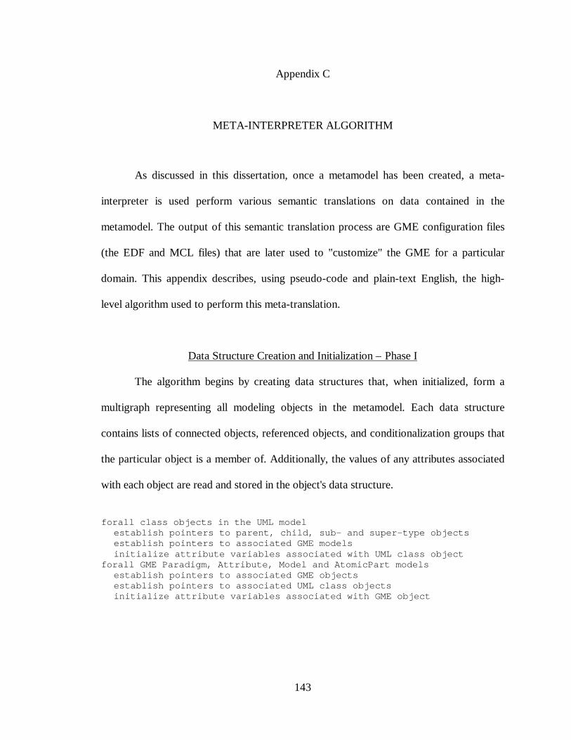
143
Appendix C
META-INTERPRETER ALGORITHM
As discussed in this dissertation, once a metamodel has been created, a meta-
interpreter is used perform various semantic translations on data contained in the
metamodel. The output of this semantic translation process are GME configuration files
(the EDF and MCL files) that are later used to "customize" the GME for a particular
domain. This appendix describes, using pseudo-code and plain-text English, the high-
level algorithm used to perform this meta-translation.
Data Structure Creation and Initialization – Phase I
The algorithm begins by creating data structures that, when initialized, form a
multigraph representing all modeling objects in the metamodel. Each data structure
contains lists of connected objects, referenced objects, and conditionalization groups that
the particular object is a member of. Additionally, the values of any attributes associated
with each object are read and stored in the object's data structure.
forall class objects in the UML modelestablish pointers to parent, child, sub- and super-type objectsestablish pointers to associated GME modelsinitialize attribute variables associated with UML class object
forall GME Paradigm, Attribute, Model and AtomicPart modelsestablish pointers to associated GME objectsestablish pointers to associated UML class objectsinitialize attribute variables associated with GME object
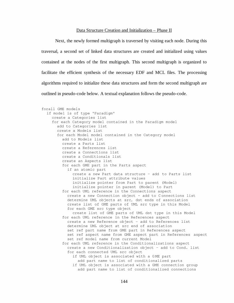
144
Data Structure Creation and Initialization – Phase II
Next, the newly formed multigraph is traversed by visiting each node. During this
traversal, a second set of linked data structures are created and initialized using values
contained at the nodes of the first multigraph. This second multigraph is organized to
facilitate the efficient synthesis of the necessary EDF and MCL files. The processing
algorithms required to initialize these data structures and form the second multigraph are
outlined in pseudo-code below. A textual explanation follows the pseudo-code.
forall GME modelsif model is of type "Paradigm"
create a Categories listfor each Category model contained in the Paradigm model
add to Categories listcreate a Models listfor each Model model contained in the Category model
add to Models listcreate a Parts listcreate a References listcreate a Connections listcreate a Conditionals listcreate an Aspects listfor each GME part in the Parts aspect
if an atomic partcreate a new Part data structure – add to Parts listinitialize Part attribute valuesinitialize pointer from Part to parent (Model)initialize pointer in parent (Model) to Part
for each UML reference in the Connections aspectcreate a new Connection object – add to C onnections listdetermine UML objects at src, dst ends of associationcreate list of GME parts of UML src type in this Modelfor each GME src type object
create list of GME parts of UML dst type in this Modelfor each UML reference in the References aspect
create a new Reference object – add to References listdetermine UML object at src end of associationset ref part name from GME part in References aspectset ref aspect name from GME aspect part in References aspectset ref model name from current Model
for each UML reference in the Conditionalizations aspectcreate a new Conditionalization object – add to Cond. listfor each connected UML src object
if UML object is associated with a GME partadd part name to list of conditionalized parts
if UML object is associated with a GME connection groupadd part name to list of conditionalized connections
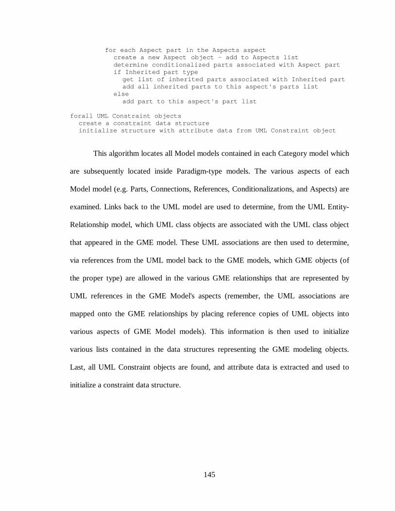
145
for each Aspect part in the Aspects aspectcreate a new Aspect object – add to Aspects listdetermine conditionalized parts associated with Aspect partif Inherited part type
get list of inherited parts associated with Inherited partadd all inherited parts to this aspect's parts list
elseadd part to this aspect's part list
forall UML Constraint objectscreate a constraint data structureinitialize structure with attribute data from UML Constraint object
This algorithm locates all Model models contained in each Category model which
are subsequently located inside Paradigm-type models. The various aspects of each
Model model (e.g. Parts, Connections, References, Conditionalizations, and Aspects) are
examined. Links back to the UML model are used to determine, from the UML Entity-
Relationship model, which UML class objects are associated with the UML class object
that appeared in the GME model. These UML associations are then used to determine,
via references from the UML model back to the GME models, which GME objects (of
the proper type) are allowed in the various GME relationships that are represented by
UML references in the GME Model's aspects (remember, the UML associations are
mapped onto the GME relationships by placing reference copies of UML objects into
various aspects of GME Model models). This information is then used to initialize
various lists contained in the data structures representing the GME modeling objects.
Last, all UML Constraint objects are found, and attribute data is extracted and used to
initialize a constraint data structure.
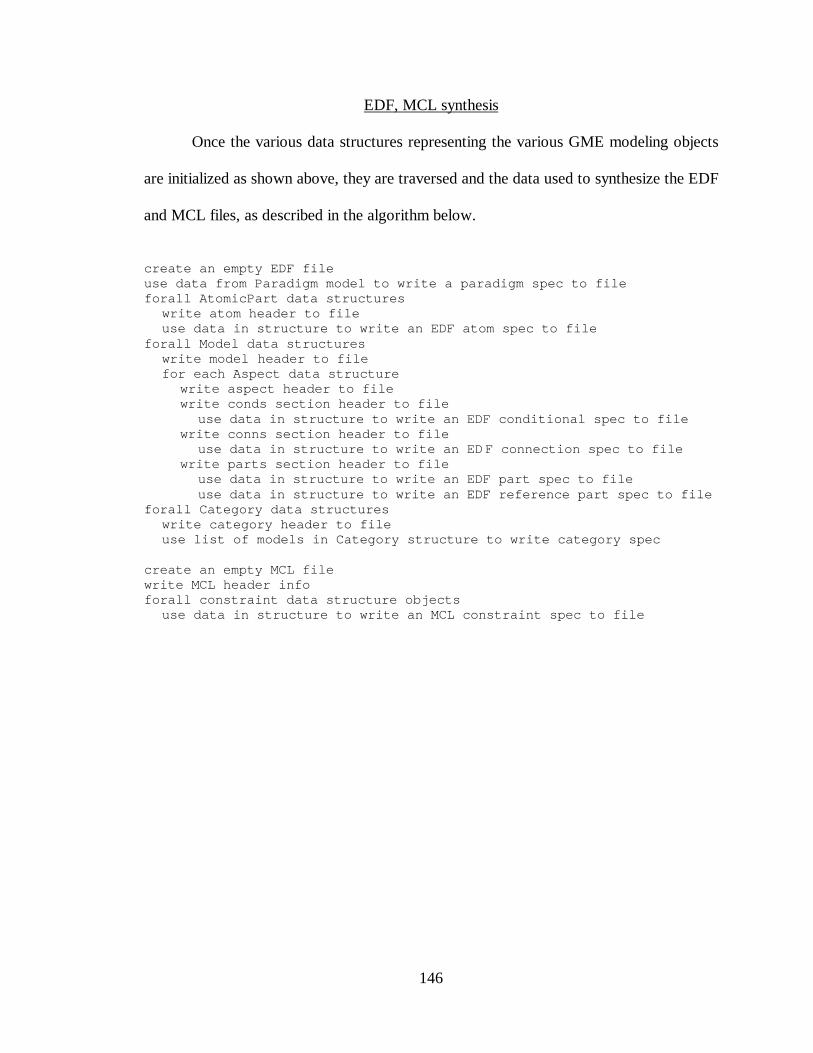
146
EDF, MCL synthesis
Once the various data structures representing the various GME modeling objects
are initialized as shown above, they are traversed and the data used to synthesize the EDF
and MCL files, as described in the algorithm below.
create an empty EDF fileuse data from Paradigm model to write a paradigm spec to fileforall AtomicPart data structures
write atom header to fileuse data in structure to write an EDF atom spec to file
forall Model data structureswrite model header to filefor each Aspect data structure
write aspect header to filewrite conds section header to file
use data in structure to write an EDF conditional spec to filewrite conns section header to file
use data in structure to write an EDF connection spec to filewrite parts section header to file
use data in structure to write an EDF part spec to fileuse data in structure to write an EDF reference part spec to file
forall Category data structureswrite category header to fileuse list of models in Category structure to write category spec
create an empty MCL filewrite MCL header infoforall constraint data structure objects
use data in structure to write an MCL constraint spec to file
147
Appendix D
THE UML/GME META-METAMODEL
The UML/GME meta-metamodel is a complete description of the UML/GME
metamodeling environment. When the meta-interpreter is used to perform a semantic
translation on the meta-metamodel, the result is a set of configuration files that can be
used to configure the GME to perform metamodeling. In other words, the UML/GME
metamodeling environment is self describing – it is capable of boot-strapping itself and
participating in its own evolution.
The UML/GME meta-metamodel was presented in Chapter V as a metamodeling
technology case study. In that study, the UML/GME meta-metamodel was compared
with the meta-metamodel used to describe the UML modeling language itself. It was
noted that, with a few exceptions related to implementing UML modeling concepts using
the GME environment, the UML/GME meta-metamodel has the same semantics as the
object modeling portion of the UML meta-metamodel. However, the case study did not
discuss other aspects of the UML/GME meta-metamodel. They are discussed below.
Specifying UML and Constraint Objects
As mentioned above, the UML object modeling portion of the UML/GME meta-
metamodel has the same semantics as the object modeling portion of the UML meta-
metamodel. For reference and as an aid to further discussions in this appendix, object
modeling portion of the UML/GME meta-metamodel is presented in Figure 28 below.
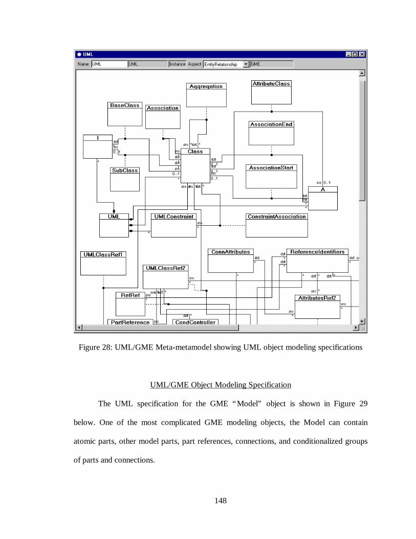
148
Figure 28: UML/GME Meta-metamodel showing UML object modeling specifications
UML/GME Object Modeling Specification
The UML specification for the GME “Model” object is shown in Figure 29
below. One of the most complicated GME modeling objects, the Model can contain
atomic parts, other model parts, part references, connections, and conditionalized groups
of parts and connections.
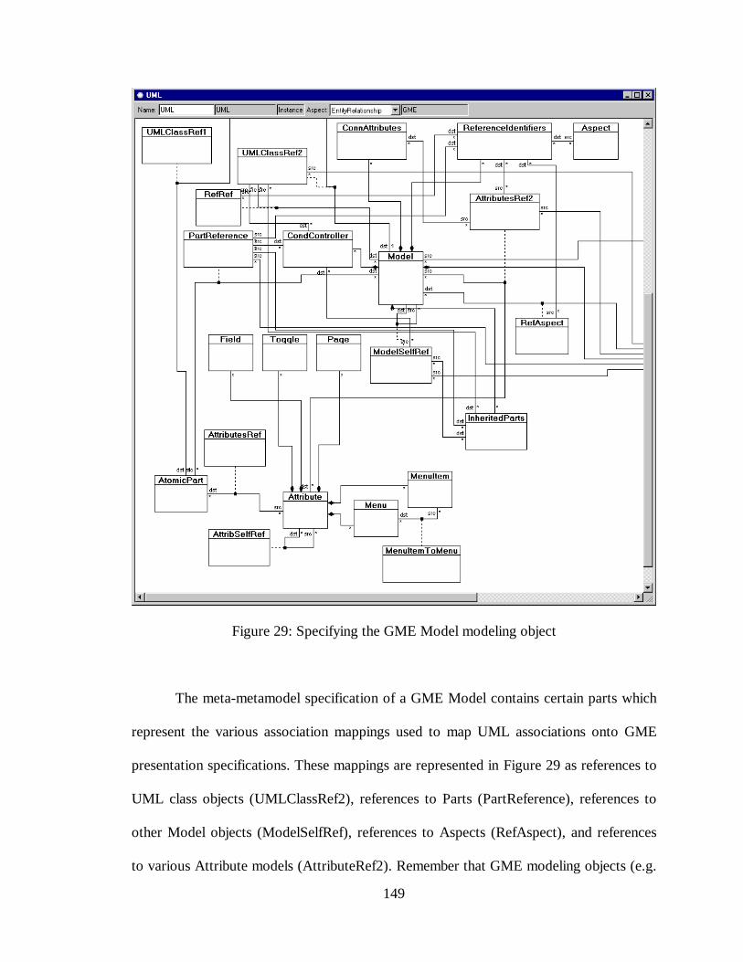
149
Figure 29: Specifying the GME Model modeling object
The meta-metamodel specification of a GME Model contains certain parts which
represent the various association mappings used to map UML associations onto GME
presentation specifications. These mappings are represented in Figure 29 as references to
UML class objects (UMLClassRef2), references to Parts (PartReference), references to
other Model objects (ModelSelfRef), references to Aspects (RefAspect), and references
to various Attribute models (AttributeRef2). Remember that GME modeling objects (e.g.
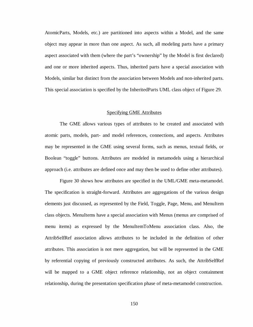
150
AtomicParts, Models, etc.) are partitioned into aspects within a Model, and the same
object may appear in more than one aspect. As such, all modeling parts have a primary
aspect associated with them (where the part’s “ownership” by the Model is first declared)
and one or more inherited aspects. Thus, inherited parts have a special association with
Models, similar but distinct from the association between Models and non-inherited parts.
This special association is specified by the InheritedParts UML class object of Figure 29.
Specifying GME Attributes
The GME allows various types of attributes to be created and associated with
atomic parts, models, part- and model references, connections, and aspects. Attributes
may be represented in the GME using several forms, such as menus, textual fields, or
Boolean “toggle” buttons. Attributes are modeled in metamodels using a hierarchical
approach (i.e. attributes are defined once and may then be used to define other attributes).
Figure 30 shows how attributes are specified in the UML/GME meta-metamodel.
The specification is straight-forward. Attributes are aggregations of the various design
elements just discussed, as represented by the Field, Toggle, Page, Menu, and MenuItem
class objects. MenuItems have a special association with Menus (menus are comprised of
menu items) as expressed by the MenuItemToMenu association class. Also, the
AttribSelfRef association allows attributes to be included in the definition of other
attributes. This association is not mere aggregation, but will be represented in the GME
by referential copying of previously constructed attributes. As such, the AttribSelfRef
will be mapped to a GME object reference relationship, not an object containment
relationship, during the presentation specification phase of meta-metamodel construction.
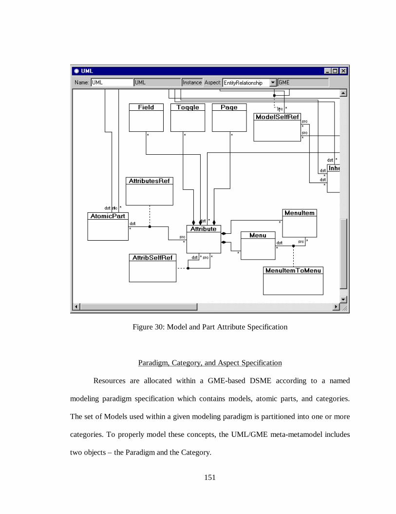
151
Figure 30: Model and Part Attribute Specification
Paradigm, Category, and Aspect Specification
Resources are allocated within a GME-based DSME according to a named
modeling paradigm specification which contains models, atomic parts, and categories.
The set of Models used within a given modeling paradigm is partitioned into one or more
categories. To properly model these concepts, the UML/GME meta-metamodel includes
two objects – the Paradigm and the Category.
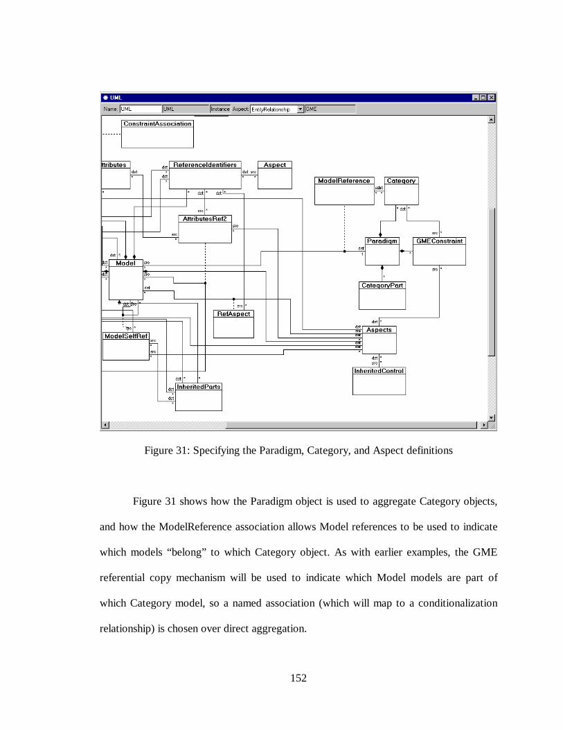
152
Figure 31: Specifying the Paradigm, Category, and Aspect definitions
Figure 31 shows how the Paradigm object is used to aggregate Category objects,
and how the ModelReference association allows Model references to be used to indicate
which models “belong” to which Category object. As with earlier examples, the GME
referential copy mechanism will be used to indicate which Model models are part of
which Category model, so a named association (which will map to a conditionalization
relationship) is chosen over direct aggregation.
153
Notice that the Paradigm object also aggregates GMEConstraint objects.
GMEConstraints are identical in structure to the UMLConstraint objects used to specify
semantic constraints in metamodels. The difference between these two types of
constraints is that GMEConstraints can appear in locations outside the UML portion of a
metamodel (for example, to constrain a portion of the presentation specification). The
meta-metamodel specification shown in Figure 31 allows a GMEConstraint to be placed
inside an Aspect specification object. This is necessary since aspects are a presentation
mechanism and not part of the “pure” syntactic or semantic behavior specified in the
UML portion of a metamodel. Notice that the Aspects class object of Figure 31 has
associations with several named association classes. These associations represent the
types of modeling objects (parts, connections, etc.) that comprise an aspect. Because the
GME metamodeling technique for modeling aspects is to allow the metamodeler to
indicate aspect partitioning by collecting several different modeling objects into a single
group, in the meta-metamodel, the Aspects class object will be mapped onto a GME
representation of conditionalization.
154
REFERENCES
[1] Sztipanovits, J.: “Engineering of Computer-Based Systems: An EmergingDiscipline,” Proceedings of the IEEE ECBS’98 Conference, 1998.
[2] White, S., et al.: “Systems Engineering of Computer-Based Systems", IEEEComputer, pp. 54-65, November 1993.
[3] UML Semantics, ver. 1.1, Rational Software Corporation, et al., September 1997.
[4] Rice, M.D. and Seidman, S.B.: “A Formal Model for Module InterconnectionLanguages”, IEEE Transactions on Software Engineering, Vol. 20, No. 1, pp. 88-101, Jan. 1994.
[5] Karsai, G., et al.: “Towards Specification of Program Synthesis in Model-IntegratedComputing", Proceedings of the IEEE ECBS’98 Conference, 1998.
[6] Aesop Software Architecture Design Environment Generator, Carnegie MellonUniversity,http://www.cs.cmu.edu/afs/cs/projects/able/www/aesop/aesop_home.html.
[7] Garlan, D., et al.: “Exploiting Style in Architecture Design Environments",Proceedings of ACM SIGSOFT Symposium on Foundations of SoftwareEngineering, 1994.
[8] Monroe, R. and Garlan, D.: “Style-Based Reuse for Software Architectures",Proceedings of the International Conference on Software Reuse, 1996.
[9] Garlan, D., Monroe, R., and Wile, D.: “ACME: An Architecture DescriptionInterchange Language", Proceedings of CASCON '97, November 1997.
[10] ACME-Web, Carnegie Mellon University, http://www.cs.cmu.edu/~acme/.
[11] Monroe, R.: “Rapid Development of Custom Software Architecture DesignEnvironments", Thesis proposal, Carnegie-Mellon University, 1996.
[12] Wile, D.: “AML: Architecture Meta-Language", Draft Report, University ofSouthern California, March 1996.
[13] Ernst, J.: "Introduction to CDIF", http//www.cdif.org.
[14] CDIF Framework for Modeling and Extensibility, Extract of Interim StandardEIA/IS-107, Electronics Industries Association, CDIF Technical Committee,January 1994.
155
[15] The Common Object Request Broker: Architecture and Specification, Revision 2.0,Object Management Group, April 1995.
[16] Lee, Edward and Sangiovanni-Vincentelli, A.: “A Denotational Framework forComparing Models of Computation", Technical Memorandum UCB/ERL M97/11,University of California at Berkeley, January 1997.
[17] Industrial Automation Systems and Integration – Product Data Representation andExchange – Part 11: Description Methods: The EXPRESS Language ReferenceManual, ISO 10303-21:1997 (E), ISO, Geneva, 1997.
[18] Industrial Automation Systems and Integration – Product Data Representation andExchange – Part 22: STEP Data Access Interface, ISO DocumentTC184/SC4/WG7 N392, ISO, Geneva, July 1994.
[19] Industrial Automation Systems and Integration – Product Data Representation andExchange – EXPRESS-X Reference Manual, ISO Document TC184/SC4/WG5,ISO, Geneva, August 1995.
[20] Industrial Automation Systems and Integration – Product Data Representation andExchange – Requirements Specification for EXPRESS Mapping Language, ISODocument TC184/SC4/WG11 N013, ISO, Geneva, January 1997.
[21] J. Rumbaugh, M. Blaha, W. Premerlani, F. Eddy, and W. Sorenson, Object-Oriented Modeling and Design, Prentice-Hall, 1991.
[22] UML Summary, ver. 1.0.1, Rational Software Corporation, March, 1997
[23] Quatrani, T.: Visual Modeling with Rational Rose and UML, Addison-Wesley,1998.
[24] Abbott, B., et al.: “Model-Based Approach for Software Synthesis,” IEEE Software,pp. 42-53, May 1993.
[25] Sztipanovits, J., et al.: “MULTIGRAPH: An Architecture for Model-IntegratedComputing,” Proceedings of the IEEE ICECCS’95, pp. 361-368, Nov. 1995.
[26] Meta-Object Facility, OMG Document ad/97-08-14, DSTC, September 1997.
[27] Distributed Systems Technology Center web site, DSTC,http://www.dstc.edu.au/Meta-Object-Facility/
[28] Object Constraint Language Specification, ver. 1.1, Rational Software Corporation,et al., Sept. 1997.
[29] The Meta-Object Facility Tutorial, DSTC, http://www.dstc.edu.au/
[30] Srinivas, Y.V. and Jüllig, R.: About Specware, Suresoft, Inc., 1996
156
[31] Waldinger, R., et al.: Specware Language Manual, KDC and Suresoft, Inc., 1996.
[32] Guttag, J.V. and Horning, J.J.: Larch: Languages and Tools for FormalSpecification, Springer-Verlag, 1993.
[33] Bourdeau, R., and Cheng, B.: “A Formal Semantics for Object Model Diagrams",IEEE Transactions of Software Engineering, Vol. 21, No. 10, October 1995.
[34] Formal Methods Specification and Analysis Guidebook for the Verification ofSoftware and Computer Systems Vol. II: A Practitioner's Companion, NASA-GB-001-97, Release 1.0, National Aeronautics and Space Administration, May 1997.
[35] Refine User’s Guide, Reasoning Systems Inc., 1990
[36] Ledeczi, A. et al.: "Metaprogrammable Toolkit for Model-Integrated Computing",Proceedings of the IEEE ECBS’98 Conference, 1999.
[37] Harel, D.: “Statecharts: A Visual Formalism For Complex Systems,” Science ofComputer Programming 8, pp. 231-278, 1987.
[38] Harel, D. and Naamad, A.: “The STATEMATE Semantics of Statecharts,” ACMTrans. Soft. Eng. Method., 5:4, Oct. 1996.
[39] Formal Methods Specification and Verification Guidebook for Software andComputer Systems Volume I, NASA-GB-002-95, Release 1.0, July 1995.
[40] Owre, S., et al.: PVS: Combining specification, proof checking, and modelchecking. In Rajeev Alur and Thomas A. Henzinger, editors, Computer-AidedVerification, CAV '96, Volume 1102 of Lecture Notes in Computer Science, pages411-414, New Brunswick, NJ, Springer-Verlag, July/August, 1996.
ELECTRICAL ENGINEERING
METAMODELING – RAPID DESIGN AND EVOLUTION OF
DOMAIN-SPECIFIC MODELING ENVIRONMENTS
GREGORY G. NORDSTROM
Dissertation under the direction of Professor Janos Sztipanovits
Model integrated computing (MIC) is an effective and efficient method for
developing, maintaining, and evolving large-scale, domain-specific software applications.
Application programs are synthesized from models created using customized, domain-
specific model integrated program synthesis (MIPS) environments. The MultiGraph
Architecture (MGA), under development at Vanderbilt University's Institute for Software
Integrated Systems, is a toolset for creating such MIPS environments.
Until now, these environments have been hand-crafted specifically for each
domain. Because common modeling concepts appear in many, if not all, MGA-based
MIPS systems, research suggests it is possible to "model the modeling environment" by
creating a metamodel – a model that describes a particular domain-specific MIPS
environment (DSME). By modeling the syntactic, semantic, and presentation
requirements of a DSME, the metamodel can be used to synthesize the DSME itself,
enabling design environment evolution in the face of changing domain requirements.
Because both the domain-specific applications and the DSME are designed to evolve,

efficient and safe large-scale computer-based systems development is possible over the
entire lifetime of the system.
This dissertation reviews current metamodeling languages and techniques,
examines available DSME resources, develops methods to represent syntactic and
semantic modeling language requirements using UML object diagrams and MultiGraph
constraint language expressions, and discusses automatic transformation of metamodel
specifications into DSMEs. Case studies are used to demonstrate metamodel
specification, creation, and translation.
Approved____________________________________________ Date______________