gxr-sd/csd/usd - mtender
TRANSCRIPT

GXR-SD/CSD/USD PREMIUM Series
Digital Radiography System
Operation Manual
DRGEM Corporation
7Fl, E-B/D Gwangmyeong Techno-Park, 60 Haan-ro,
Gwangmyeong-si, Gyeonggi-do, 14322, Korea
TEL: +82-2-869-8566, FAX: +82-2-869-8567
D/N: RMD1412-002, Rev. 11

DRGEM Corporation
Page 2 RMD1412-002, Rev. 11 Operation Manual
(This page intentionally left blank)

GXR-SD/CSD/USD PREMIUM
Service Manual RMD1412-002, Rev.11 Page 3
REVISION HISTORY
Revision Number Date Description
0 DEC 12, 2014 First Edition
1 DEC 17, 2016 Add Ceiling auto stitching function
2 JUN 20, 2017 Transition of NB (DNV-GL NB# 0434 -> DNV GL NE
MKO PRESAFE AS NB#2460),
3 AUG 21, 2017
Add the collimator (DXC-RM)
Add the Motorized Type Equipment (TS_FC2. TS_FC4,
TS_FC6, WBS-TM, WBS)
Add the auto stitching function(TS_FM6, TS,FC6)
4 APR 09, 2018 Add new Graphic User Interface
5 NOV 10, 2018
Change Standard(EMC 4 , Safety 3.1)
Add Mano Detector(Mano4343X, Mano434T)
Change name of manufacture for Tube.
(TOSHIBA -> CANON, VARIAN -> VAREX)
6 MAR 15, 2019 Add the TS_CSP.
Add the 1100mm longitudinal Option for PBT-6
7 JUL 19, 2019
Add the Ceiling Rail of Option for TS_FM6
Change of Bucky size for Wall bucky Stand.
Add Mano Detector(Mano4343W, Mano4336W)
Add Varex Detector(4343RC)
8 DEC 11, 2019 Add Built-in Memory function.
9 APR 16, 2020
Addition of XRPad2, PaxScan4343W, VIVIX-S series
Detectors
Separate RADMAX SOFTWARE content.
Refer to the RADMAX manual(RMD1804-001)
10 APR 27, 2020 Added Worklist Function.
Added Mechanical detent (option)
11 MAY 04, 2020 Apply the tube arm detent for TS_FM6, TS_FC6

DRGEM Corporation
Page 4 RMD1412-002, Rev. 11 Operation Manual
ADVISORY SYMBOLS
The following advisory symbols are used throughout this manual.
Their application and meaning are described below.
Warning symbol is used to indicate a potential hazard for operators
and service personnel that can lead to serious injury, death or
radiation exposure.
Caution symbol is used to indicate a potential hazard for operators
and service personnel that can lead to injury or damage of
equipment.
Note symbol is used to indicate important information needed for
proper use and correct operation of equipment.
Keep this Software Manual with the equipment at all times, and review
the important information whenever required.
Copyright DRGEM Corporation. All rights reserved.
This document is the property of DRGEM Corporation and contains confidential and proprietary information
owned by DRGEM Corporation. Any unauthorized copying, use or disclosure of it without the prior written
permission of DRGEM Corporation is strictly prohibited.
Consult Accompanying Documents - As Applicable

GXR-SD/CSD/USD PREMIUM
Service Manual RMD1412-002, Rev.11 Page 5
INDICATIONS for USE STATEMENT:
The GXR-SD/CSD/USD Series Diagnostic X-Ray System, is a stationary X-ray imaging system, for the
purpose of acquiring X-ray images of the desired parts of a patient’s anatomy. This device is not
intended for mammography or bone density applications.
U.S. A. Federal law restricts this device to sale by or on
the order of a physician.
Information provided by the product are adjunctive
(supporting) and should not be solely or primarily relied
upon to diagnose or treat COVID-19
This device is not indicated for the diagnosis of COVID-
19 and that in vitro diagnostic testing is currently the
only definitive method to diagnose COVID-19.

DRGEM Corporation `
Page 6 RMD1412-002, Rev. 11 Operation Manual
(This page intentionally left blank)

GXR-SD/CSD/USD PREMIUM
Service Manual RMD1412-002, Rev.11 Page 7
TABLE OF CONTENTS
1. INTRODUCTION .............................................................................................................. 9
1.1 INTENDED USE & FEATURES ........................................................................................... 9
1.2 SAFETY INFORMATION ................................................................................................... 10
1.2.1 STATEMENT OF LIABILITY ...................................................................................................... 10
1.2.2 SYMBOL DEFINITIONS ............................................................................................................ 11
1.2.3 SAFETY GUIDELINES .............................................................................................................. 13
1.2.4 X-RAY PROTECTION ............................................................................................................... 17
1.2.5 PEDIATRIC USE : SUMMARY .................................................................................................. 20
1.2.6 RADIATION SAFETY ................................................................................................................ 21
1.2.7 MANUFACTURER’S RESPONSIBILITY ................................................................................... 24
1.2.8 MONITORING PERSONNEL .................................................................................................... 25
1.2.9 RADIATION PROTECTION SURVEY ....................................................................................... 26
1.3 APPLICATION SPECIFICATION ....................................................................................... 27
1.3.1 INTENDED MEDICAL INDICATION .......................................................................................... 27
1.3.2 INTENDED PATIENT POPULATION ........................................................................................ 27
1.3.3 INTENDED USER PROFILE ..................................................................................................... 27
1.4 SPECIFICATIONS ............................................................................................................. 29
1.5 CUSTOMER SUPPORT ..................................................................................................... 56
2. OPERATION PROCEDURE .......................................................................................... 57
2.1 TURN ON THE SYSTEM ................................................................................................... 57
2.2 EXAMINATION .................................................................................................................. 58
2.3 TURN OFF THE SYTSTEM ............................................................................................... 58
3. RADMAX SOFTWARE .................................................................................................. 59
4. X-RAY CONTROL .......................................................................................................... 61
4.1 SAFETY NOTICE .............................................................................................................. 62
4.2 GENERATOR DUTY CYCLE LIMIT .................................................................................. 63
4.3 DAILY X-RAY TUBE WARM-UP PROCEDURE ............................................................... 64
4.4 GENERATOR INTERFACE MODULE ............................................................................... 65
4.5 CONSOLE CONTROLS .................................................................................................... 66
4.5.1 POWER ON/OFF CONTROLS .................................................................................................. 66
4.5.2 INDICATOR ............................................................................................................................... 66
4.5.3 PROCEDURE DISPLAY ............................................................................................................ 66
4.5.4 PREP, X-RAY EXPOSURE CONTROL .................................................................................... 67
4.5.5 RADIOGRAPHY CONTROLS ................................................................................................... 67

DRGEM Corporation `
Page 8 RMD1412-002, Rev. 11 Operation Manual
4.5.6 STATE MESSAGE DISPLAY .................................................................................................... 71
4.5.7 COLLIMATOR CONTROL ......................................................................................................... 72
4.5.8 SYSTEM STATUS INDICATOR ................................................................................................ 73
5. APPARATUS OPERATION ............................................................................................ 75
5.1 TUBE STAND (TS-FM6, TS_FC6, TS_FC4 - VERTICAL MOTORIZED MOVEMENT) ...... 75
5.2 TUBE STAND (TS-FC2-VERTICAL MOTORIZED MOVEMENT) ...................................... 85
5.3 TUBE STAND (TS-CSA) .................................................................................................... 86
5.4 TUBE STAND (TS-CSP) .................................................................................................... 95
5.5 VERTICAL WALL STAND (WBS, WBS-TA, WBS-TM) ................................................... 101
5.6 PATIENT TABLES ........................................................................................................... 106
5.7 COLLIMATOR ................................................................................................................. 108
APPENDIX A. EXPOSURE TABLE ................................................................................. 111
APPENDIX B. EXPOSURE INDEX .................................................................................. 115

1. INTRODUCTION GXR-SD/CSD/USD PREMIUM
Service Manual RMD1412-002, Rev.11 Page 9
1. INTRODUCTION
This manual contains the necessary instructions for proper operation of GXR-SD/CSD/USD PREMIUM
System. All persons operating this equipment need to have read this manual beforehand. You must have a
thorough understanding in the proper use of this product before you make any radiographic exposures.
1.1 INTENDED USE & FEATURES
This diagnostic x-ray system is designed to diagnose human body by providing radiographic x-ray image with
anatomical structure
This GXR-SD/CSD/USD PREMIUM System “is for use by medical professionals”
To prevent excess radiation exposure to patient and operator from either primary or secondary radiation, this
GXR-SD/CSD/USD PREMIUM System must be operated and serviced by trained personnel who are familiar
with the safety precautions required.
GXR-SD/CSD/USD PREMIUM System provides state-of-the-art image quality; image processing and user
interface; making the system easy to use and reliable while providing high quality digital radiographic images
with reduced dose.
GXR-SD/CSD/USD PREMIUM System incorporates the digital flat panel detector technology.
Direct radiography via flat panel detector improves your workflow, exam speed and comfort with efficiency.
Digital flat panel detector provides excellent spatial resolution, MTF, DQE and stability based on fine pixel pitch.
Selection of an anatomical study on the imaging software automatically sets up the x-ray generator’s pre-
programmed exposure technique setting and post image processing for selected study. Also, high resolution
grid supplies excellent image quality.
A high performance imaging workstation and RADMAX software serves you a convenient interface and easy
operation. Anatomical view-based digital image processing automatically optimizes and enhances the quality of
the captured images. Automatic image storage and print with DICOM 3.0 networking capability increases exam
throughput and decreases examination time. Remote diagnosis function enables fast and accurate diagnosis
on problems and saves service cost and system downtime.

DRGEM Corporation ` 1. INTRODUCTION
Page 10 RMD1412-002, Rev. 11 Operation Manual
1.2 SAFETY INFORMATION
The policy of DRGEM Corporation is to manufacture X-ray equipment that meets high standards of
performance and reliability. We enforce strict quality control techniques to eliminate the potential for defects and
hazards in our products. The intended use of this equipment is to provide an X-ray source for the purpose of
acquiring X-ray images of the desired parts of a patient’s anatomy. Use of this equipment in any other fashion
may lead to serious personal injury. The safety guidelines provided in this section of the manual are intended to
educate the operator on all safety issues in order to operate and maintain GXR-SD/CSD/USD PREMIUM
System in a safe manner.
1.2.1 STATEMENT OF LIABILITY
To prevent excess radiation exposure to patient and operator from either primary or secondary radiation, this
GXR-SD/CSD/USD PREMIUM System must be operated and serviced by trained personnel who are familiar
with the safety precautions required. While this GXR-SD/CSD/USD PREMIUM System has been designed for
safe operation, improper operation or carelessness may result in serious injury or damage to equipment. The
manufacturer or its agents and representatives assume no responsibility for the following:
1. Injury or danger to any person from x-ray exposure.
2. Overexposure due to poor technique selection.
3. Injury or danger from improper use of the function.
4. Problems or hazards resulting from failure to maintain the equipment as specified in the Installation chapter.
5. Equipment which has been tampered with or modified. DRGEM Corporation is not liable for any damage
or injury arising from failure to follow the instructions and procedures provided within the manuals or
associated informational material, or from user failure to use caution when installing, operating, adjusting,
or servicing this equipment. DRGEM Corporation is not liable for damage or injury arising from the use of
this product for any other use than that intended by the manufacturer.

1. INTRODUCTION GXR-SD/CSD/USD PREMIUM
Service Manual RMD1412-002, Rev.11 Page 11
1.2.2 SYMBOL DEFINITIONS
The table below defines the meaning of various symbols used on labels on the machine.
Radiation exposure symbol used on operator
console. Lights to indicate that an exposure is in
progress. This is accompanied by an audible tone
from the console.
Radiation warning message on console.
Never allow unqualified personnel to operate the X-
ray generator.
Sitting at the end of tabletop is prohibited.
Consult accompanying documents (Required to
consult for Safety)
Emergency Stop
Caution for trapping zone of hand
This symbol means that the product and battery
should be recycled separately from household
waste. When this product reaches its end of life,
follow the local laws and regulations of disposal. The
improper disposal of waste electronic equipment
from the consumer may be subject to fines.

DRGEM Corporation ` 1. INTRODUCTION
Page 12 RMD1412-002, Rev. 11 Operation Manual
Caution of laser radiation.
Staring into beam is never allowed.
High voltage symbol used to indicate the presence
of high voltage.
Warning symbol used to indicate a potential hazard
to operators, service personnel or to the equipment.
It indicates a requirement to refer to the
accompanying documentation for details.
Protection earth symbol
L Live line among the single phase line powers.
N Neutral line among the single phase line powers.
L1 First phase line power among the three phase line
powers.
L2 Second phase line power among the three phase
line powers.
L3 Third phase line power among the three phase line
powers.
V~ Single phase AC voltage
V3~ Three phase AC voltage
V DC voltage

1. INTRODUCTION GXR-SD/CSD/USD PREMIUM
Service Manual RMD1412-002, Rev.11 Page 13
1.2.3 SAFETY GUIDELINES
The following are general safety precautions:
Only qualified personnel may use this software.
Do not defeat or bypass built-in equipment safety features.
Observe all warnings and cautions, stated or implied, in the procedures.
To protect the system and data from Virus, Spam, spoofing, Phishing, Pharming, Spyware, Keylogging,
Adware, Botnets, Worms, Trojan, Denial-Of-Service such as online attack and etc., it is important to
install the proper Anti-Virus software in the workstation.
Pediatric patients are more radiosensitive than adults (i.e., the cancer risk per unit dose of ionizing radiation
is higher);
Use of equipment and exposure settings designed for adults may result in excessive radiation exposure if
used on smaller patients;
Pediatric patients have a longer expected lifetime, putting them at higher risk of cancer from the effects of
radiation exposure.
To protect the system and data from Virus, Spam, spoofing, Phishing, Pharming, Spyware, Keylogging,
Adware, Botnets, Worms, Trojan, Denial-Of-Service such as online attack and etc., it is important to
install the proper Anti-Virus software in the workstation.
The following warnings and cautions are specific to GXR-SD/CSD/USD PREMIUM System.
Read them carefully - some of them are not obvious to typical use.
X-ray radiation exposure may be damaging to health, with some effects being cumulative and extending over
periods of many months or even years. X-ray operators should avoid any exposure to the primary beam
and take protective measures to safeguard against scatter radiation. Scatter radiation is caused by any object
in the path of the primary beam and may be of equal or less intensity than the primary beam that exposes the
film.
No practical design can incorporate complete protection for operators or service personnel who do not take
adequate safety precautions. Only authorized and properly trained service and operating personnel
should be allowed to work with this X-ray generator equipment. The appropriate personnel must be made
aware of the inherent dangers associated with the servicing of high voltage equipment and the danger of
excessive exposure to X-ray radiation during system operation.
Wear protective clothing. Protective aprons with an equivalent of a minimum of 1/64” (0.35 mm) of lead are
recommended.
To protect the patient against radiation, always use radiation protection accessories in addition to devices
which are fitted to the X-ray equipment.
Keep as large a distance as possible away from the object being exposed and the X-ray tube assembly.

DRGEM Corporation ` 1. INTRODUCTION
Page 14 RMD1412-002, Rev. 11 Operation Manual
Never operate this X-ray equipment in areas where there is a risk of explosion. Detergents and disinfectants,
including those used on patients, may create explosive mixtures of gases. Please observe the relevant
regulations.
The operator console, or anything electrically connected to it, must never be used within 6 ft (1.8 m) of the
patient environment.
Do not place liquids (coffee, beverages, flowers, etc) on the control console or generator main cabinet.
Always ensure adequate ventilation around the control console and generator main cabinet. Do not operate
the equipment near curtains, drapes, etc which may block the ventilation slots.
Do not operate the console or generator main cabinet in direct sunlight or near any heat sources.
Do not operate the console near strong magnetic fields (microwave ovens, speakers, etc), and avoid routing
the console cables near these devices.
The console and generator main cabinet must be operated in locations that are clean (free of excess dust,
dirt, debris, etc), stable (free of vibration), and secure such that the console cannot slip or tip.
Only trained maintenance staff may remove the covers of the generator cabinet and the control console.
INCORRECT CONNECTIONS OR USE OF UNAPPROVED EQUIPMENT MAY
RESULT IN INJURY OR EQUIPMENT DAMAGE.
THIS X-RAY UNIT MAY BE DANGEROUS TO PATIENT AND OPERATOR
UNLESS SAFE EXPOSURE FACTORS AND OPERATING INSTRUCTIONS
ARE OBSERVED.
PROPER USE AND SAFE OPERATING PRACTICES WITH RESPECT TO X-
RAY GENERATORS ARE THE RESPONSIBILITY OF THE USERS OF SUCH
GENERATORS.
MANUFACTURER PROVIDES INFORMATION ON ITS PRODUCTS AND
ASSOCIATED HAZARDS, BUT ASSUMES NO RESPONSIBILITIES FOR
AFTER-SALE OPERATING AND SAFETY PRACTICES.
MANUFACTURER ACCEPTS NO RESPONSIBILITY FOR ANY GENERATOR
NOT MAINTAINED OR SERVICED ACCORDING TO THE SERVICE MANUAL
OR ANY GENERATOR THAT HAS BEEN MODIFIED IN ANY WAY.
MANUFACTURER ALSO ASSUMES NO RESPONSIBILITY FOR X-RAY
RADIATION OVEREXPOSURE OF PATIENTS OR PERSONNEL RESULTING
FROM POOR OPERATING TECHNIQUES OR PROCEDURES.

1. INTRODUCTION GXR-SD/CSD/USD PREMIUM
Service Manual RMD1412-002, Rev.11 Page 15
DO NOT EXCEED THE TUBE MAXIMUM OPERATING LIMITS.
INTENDED LIFE AND RELIABILITY WILL NOT BE OBTAINED UNLESS
GENERATORS ARE OPERATED WITHIN PUBLISHED SPECIFICATIONS.
Do not remove flexible high tension cables from X-ray tube housing or X-ray
generator and/or access covers from X-ray generator until the main and auxiliary
power supplies have been disconnected and allowed to discharge for at least 3
minutes. You can be fatally shocked if you do not.
Voltage as high as 100,000 volts may be present in the GXR-SD/CSD/USD
PREMIUM system circuitry for a few minutes after it has been turned off.
All of the movable assemblies and parts of this equipment should be operated with
care and routinely inspected in accordance with the manufacturer’s
recommendations contained in this manual. Only properly trained and qualified
personnel should be permitted access to any internal parts. Live electrical terminals
are deadly; be sure line disconnect switches are opened and other appropriate
precautions are taken before opening access doors, removing enclosure panels, or
attaching accessories. For all components of the equipment, protective earthing
means must be provided in compliance with the national regulations.
X-rays generate a potential risk for both patients and operators. For this reason, the
application of X-rays for a given medical purpose must aim at the minimization of
radiation exposition to any persons. Those persons responsible for the application
must have the specific knowledge according to legal requirements and regulations
and must establish safe exposure procedures for this kind of systems. Those persons
responsible for the planning and installation of this equipment must observe the
national regulations.
Operators must meet all state and local requirements and regulations.
Only qualified personnel may operate GXR-SD/CSD/USD PREMIUM System.
Operation of the equipment by persons who have not been trained or who are
unfamiliar with GXR-SD/CSD/USD PREMIUM System may cause serious injury to
the patient, serious injury to the operator, or equipment damage.

DRGEM Corporation ` 1. INTRODUCTION
Page 16 RMD1412-002, Rev. 11 Operation Manual
Before operating GXR-SD/CSD/USD PREMIUM System, operators must familiarize
themselves with the location of the room’s main power switch or the generator’s main
switch in order to enable immediate shutdown of the x-ray tube in the event of
unintended motion or other catastrophic equipment failure.
The GXR-SD/CSD/USD PREMIUM system includes no user serviceable parts. For
service assistance, contact DRGEM Corporation or service provider.
The GXR-SD/CSD/USD PREMIUM system produces ionizing radiation. Operators
must meet all state and local requirements and regulations.
The GXR-SD/CSD/USD PREMIUM system and associated cables must not be
operated in the presence of moisture.
Ensure that the earth grounding connections between the GXR-SD/CSD/USD
PREMIUM system and its power source are maintained at all times.
The GXR-SD/CSD/USD PREMIUM system is not suitable for operation in the
presence of a flammable anesthetic mixture with air, oxygen, or nitrous oxide.
Disconnect electrical power from the GXR-SD/CSD/USD PREMIUM system before
servicing. Use care not to drop tools or other objects into the GXR-SD/CSD/USD
PREMIUM system when working on or around the unit. Electrical shock could result.
Table top moves for correct position of patient by operator’s continuous
operation.
When it moves for examination it accompany hole under side that can cause
serious damage to your hand.
Be careful not to insert your hand in this hole.
Use of this equipment adjacent to or stacked with other equipment should be
avoided because it could result in improper operation. If such use is necessary,
this equipment and the other equipment should be observed to verify that they are
operating normally.

1. INTRODUCTION GXR-SD/CSD/USD PREMIUM
Service Manual RMD1412-002, Rev.11 Page 17
CONTRINDICATION
There are no medical conditions that would make having an X-Ray unsuitable. However, for women who are or
might be pregnant, it is advised that certain X-Rays are not undertaken other than in emergency situations.
This System is not intended to use of mammography and bone density
This System is not suitable for operation in the presence of a flammable anesthetic mixture with air, oxygen, or
nitrous oxide.
1.2.4 X-RAY PROTECTION
X-ray equipment may cause injury if used improperly. The instructions contained in this manual must be read
and followed when operating the GXR-SD/CSD/USD PREMIUM System. No practical design can provide
complete protection nor prevent operators from exposing themselves or others to unnecessary radiation.
Personal radiation monitoring and protective devices are available. You are urged to use them to protect against
unnecessary radiation exposure.
Serious unfavorable health effects can result from short term exposure to high levels of ionizing radiation (such
as X-rays) as well as from long term exposure to low levels. Personnel who operate the GXR-SD/CSD/USD
PREMIUM System should familiarize themselves with both the short term and the long term effects of radiation
exposure and take appropriate measures to minimize the amount of radiation to which they are exposed while
performing their duties. Some effects of X-radiation are cumulative, and may extend over a period of months or
years. The best safety rule for X-ray operators is to avoid exposure to the primary beam at all times.
Ionizing radiation occurs naturally in the environment. It is generated by astronomical radiation sources such
as the sun and the stars, and by the soil under our feet. The atmosphere filters radiation from astronomical
sources. As a result, the radiation level from these sources is much lower at sea level than on the summit of
high mountains. Radiation generated in the soil varies greatly from place to place depending on the composition
of the soil. For example, areas rich in granite rock have a higher level of radiation than other areas.
Any materials placed in the path of the beam absorb natural as well as man-made radiation, such as the X-
rays used in the GXR-SD/CSD/USD PREMIUM System.
Materials with a high atomic number, such as tungsten, lead, and uranium, absorb X-rays much more effectively
than materials with a low atomic number such as hydrogen, aluminum, or beryllium. Therefore, lead is used for
shielding the radiologist's workstation in most X-ray facilities, including ones using the GXR-SD/CSD/USD
PREMIUM System.
If there are windows in the partition separating the operator from the patient, these windows are typically glazed
with lead glass and provide effective protection against ionizing radiation.

DRGEM Corporation ` 1. INTRODUCTION
Page 18 RMD1412-002, Rev. 11 Operation Manual
To minimize dangerous exposure, use movable lead screens, lead-impregnated gloves, and lead-impregnated
aprons. These protective devices must contain 0.35 millimeter thickness of lead or the equivalent.
Use such protective devices for all operators, observers, and/or servicing personnel exposed to radiation fields
of five or more milli-Roentgens per hour.
The shielding provided for a typical X-ray facility's operator workstation is generally quite effective and reduces
the residual radiation from diagnostic X-rays to a level that is comparable to or lowers than natural background
radiation. If the operator abandons the protected environment of the workstation, he or she may be exposed to
a significantly higher level of radiation. For a single exposure this may still not lead to serious health effects, but
repeated carelessness in this regard may lead to serious consequences.
Any object in the path of the primary beam produces scattered radiation. In the absence of proper precautions,
scattered radiation can result in a substantial radiation dose to the operator or any other personnel in the facility.
Moveable screens may be used to shield occupied areas from scattered radiation.
The X-ray Generator/host system used to power the GXR-SD/CSD/USD PREMIUM System only produces X-
rays when high voltage is applied to the X-ray tube. When the high voltage is removed, X-ray emission ceases
without delay.
THIS UNIT MAY BE DANGEROUS TO OPERATOR UNLESS SAFE
OPERATING INSTRUCTIONS ARE OBSERVED.
PROPER USE AND SAFE OPERATING PRACTICES WITH RESPECT
TO GXR-SD/CSD/USD PREMIUM SYSTEM ARE THE
RESPONSIBILITY OF USERS. DRGEM CORPORATION PROVIDES
INFORMATION ON ITS PRODUCTS AND ASSOCIATED HAZARDS,
BUT ASSUMES NO RESPONSIBILITIES FOR AFTER-SALE
OPERATING AND SAFETY PRACTICES.
THE MANUFACTURER ACCEPTS NO RESPONSIBILITY FOR ANY
GXR-SD/CSD/USD PREMIUM SYSTEM NOT MAINTAINED OR
SERVICED ACCORDING TO THIS MANUAL, OR FOR ANY GXR-
SD/CSD/USD PREMIUM SYSTEM THAT HAS BEEN MODIFIED IN ANY
WAY.
No practical design can incorporate complete protection for operators or service personnel who do not take
adequate safety precautions. Only authorized and properly trained service and operating personnel
should be allowed to work with this system. The appropriate personnel must be made aware of the inherent
dangers associated with the servicing of X-ray equipment.

1. INTRODUCTION GXR-SD/CSD/USD PREMIUM
Service Manual RMD1412-002, Rev.11 Page 19
* Inverse square law
A bundle of X-rays corresponds to the shape of a cone, with the tube at its tip. The intensity or
dose of the radiation emitted from the source of the X-ray beam diminishes with the square of its
distance from the source. If you double the distance x, the dose changes by a factor of 1/(2²), and
if you triple it, the dose changes by a factor of 1/(3²).
In general, the dose amounts to 1/x². Therefore, if you double the film-to-target distance, you will need
four times as much radiation to achieve the same image blackening. If you did not change the patient's
position, this would lead to radiation stress in the patient; thus, increasing the distance between X-ray
tube and patient helps to reduce the dose.
No practical design can incorporate complete protection for operators or service personnel who do not take
adequate safety precautions. Only authorized and properly trained service and operating personnel
should be allowed to work with this system. The appropriate personnel must be made aware of the inherent
dangers associated with the servicing of X-ray equipment.
Fig: Inverse square law

DRGEM Corporation ` 1. INTRODUCTION
Page 20 RMD1412-002, Rev. 11 Operation Manual
1.2.5 PEDIATRIC USE : SUMMARY
General Information: Special care should be exercised when imaging patients outside the typical adult
size range, especially smaller pediatric patients whose size does not overlap the adult size range (e.g.,
patients less than 50 kg (110 lb.) in weight and 150 cm (59 in) in height, measurements, which
approximately correspond to that of an average 12-year-old or a 5th percentile U.S. adult female).
Exposure to ionizing radiation is of particular concern in pediatric patients because:
1) for certain organs and tumor types, younger patients are more radiosensitive than adults (i.e., the cancer
risk per unit dose of ionizing radiation is higher for younger patients);
2) use of equipment and exposure settings designed for adults of average size can result in excessive and
unnecessary radiation exposure of smaller patients; and
3) younger patients have a longer expected lifetime over which the effects of radiation exposure may
manifest as cancer.
USE SPECIAL CARE WHEN IMAGING PATIENTS OUTSIDE THE
TYPICAL ADULT SIZE RANGE.
References for pediatric dose optimization: The following resources provide information about pediatric
imaging radiation safety and/or radiation safety for general radiography devices:
FDA’s website provides radiation safety information references from a variety of groups including
the Image Gently Alliance: Pediatric X-ray Imaging;http://www.fda.gov/Radiation-
EmittingProducts/RadiationEmittingProductsandProcedures/ucm298899.htm
and Medical X-ray Imaging (http://www.fda.gov/Radiation-
EmittingProducts/RadiationEmittingProductsandProcedures/MedicalImaging/MedicalX-
Rays/default.htm).
In addition, FDA’s Pediatric X-ray Imaging Website (https://www.fda.gov/radiation-
emittingproducts/radiationemittingproductsandprocedures/medicalimaging/ucm298899.htm)

1. INTRODUCTION GXR-SD/CSD/USD PREMIUM
Service Manual RMD1412-002, Rev.11 Page 21
1.2.6 RADIATION SAFETY
Everyone associated with X-ray work must be familiar with the recommendations of the Center for Devices and
Radiological Health (CDRH), the National Institute for Standards and Technology (NIST), the National Council
on Radiation Protection (NCRP), and the International Committee on Radiation Protection (ICRP).
Be sure that all personnel authorized to operate the X-ray system are familiar with the established regulations
of the authorities named above. All personnel should be monitored to ensure compliance with recommended
procedures.
Current sources of information include:
National Council on Radiation Protection Report No. 33
(“Medical X-ray and gamma ray Protection for Energies up to 10 MEV-Equipment Design and Use”).
National Bureau of Standards Handbook No. 76 (“Medical X-ray Protection up to Three Million Volts”).
Refer to NCRP Report No. 33.
Current recommendations of the International Committee on Radiation Protection.
Although X-radiation is hazardous, X-ray equipment does not pose any danger when properly used. Be certain
all operating personnel are properly educated concerning the hazards of radiation. Persons responsible for the
system must understand the safety requirements and special warnings for X-ray operation. Review this manual
and the manuals for each component in the system to become aware of all safety and operational requirements.
Ensure exposure parameters are properly adjusted within safety limits.
Incorrectly positioning the X-ray tube and Collimator could cause the X-ray field to
be misaligned with the Bucky, resulting in unacceptable images.
Radiation Effects
Acute Effects: Short term effects
Very large radiation exposures can kill humans. The lethal dose (LD) for half the population (50%) within 60
days is termed the LD50/60d. The LD50/60d in humans from acute, whole body radiation exposure is
approximately 400 to 500 rads (4-5 Gy). The temperature elevation in tissue caused by the energy imparted is
much less than 1° C. The severe biological response is due to ionizing nature of X-ray radiation, causing the
removal of electrons, and thereby chemical changes in molecular structures.
DRGEM Corporation ` 1. INTRODUCTION
Page 22 RMD1412-002, Rev. 11 Operation Manual
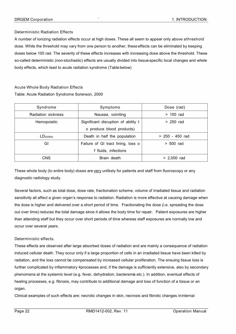
Deterministic Radiation Effects
A number of ionizing radiation effects occur at high doses. These all seem to appear only above a threshold
dose. While the threshold may vary from one person to another, these effects can be eliminated by keeping
doses below 100 rad. The severity of these effects increases with increasing dose above the threshold. These
so-called deterministic (non-stochastic) effects are usually divided into tissue-specific local changes and whole
body effects, which lead to acute radiation syndrome (Table below)
Acute Whole Body Radiation Effects
Table: Acute Radiation Syndrome Sorenson, 2000
Syndrome Symptoms Dose (rad)
Radiation sickness Nausea, vomiting > 100 rad
Hemopoietic Significant disruption of ability t
o produce blood products)
> 250 rad
LD50/60d Death in half the population > 250 - 450 rad
GI Failure of GI tract lining, loss o
f fluids, infections
> 500 rad
CNS Brain death > 2,000 rad
These whole body (to entire body) doses are very unlikely for patients and staff from fluoroscopy or any
diagnostic radiology study.
Several factors, such as total dose, dose rate, fractionation scheme, volume of irradiated tissue and radiation
sensitivity all affect a given organ’s response to radiation. Radiation is more effective at causing damage when
the dose is higher and delivered over a short period of time. Fractionating the dose (i.e. spreading the dose
out over time) reduces the total damage since it allows the body time for repair. Patient exposures are higher
than attending staff but they occur over short periods of time whereas staff exposures are normally low and
occur over several years.
Deterministic effects.
These effects are observed after large absorbed doses of radiation and are mainly a consequence of radiation
induced cellular death. They occur only if a large proportion of cells in an irradiated tissue have been killed by
radiation, and the loss cannot be compensated by increased cellular proliferation. The ensuing tissue loss is
further complicated by inflammatory 4processes and, if the damage is sufficiently extensive, also by secondary
phenomena at the systemic level (e.g. fever, dehydration, bacteremia etc.). In addition, eventual effects of
healing processes, e.g. fibrosis, may contribute to additional damage and loss of function of a tissue or an
organ.
Clinical examples of such effects are: necrotic changes in skin, necrosis and fibrotic changes in internal

1. INTRODUCTION GXR-SD/CSD/USD PREMIUM
Service Manual RMD1412-002, Rev.11 Page 23
organs, acute radiation sickness after whole body irradiation, cataract, and sterility (table below).
Doses required to produce deterministic changes are in most cases large (usually in excess
of 1-2 Gy). Some of those occur in a small proportion of patients as side effects of radiotherapy. They
can also be found after complex interventional investigations (such as vascular stenting) when long
fluoroscopy times have been used.
Table:
Deterministic effects after whole-body and localized irradiation by X and gamma rays; approximate
absorbed threshold doses for single (short-term) and fractionated or low dose-rate (long-term) exposures [5,6].
Organ/tissue
Effect
Threshold absorbed dose Gy
Short-term exposure
(single doses)
Long-term exposure
(Yearly - repeated for
many years)
Testicles
Temporal sterility
permanent sterility
0.15
3.5 - 6.0
0.4
2.0
Ovaries Sterility 2.5 - 6.0 > 0.2
Ocular lens Detectable
opacities
Visual impairment
(cataract)
0.5 - 2.0
5.0
> 0.1
> 0.15
Bone marrow
Haemopoiesis
impairment
0.5 > 0.4
Skin
1.Erythema (dry
desquamation).
2. Moist
desquamation.
3. Epidermal and
deep skin necrosis
4. Skin atrophy with
complications
and telangiectasia
2
18
25
10-12
-
-
-
1.0
Whole body
Acute radiation
sickness (mild)
1.0
-

DRGEM Corporation ` 1. INTRODUCTION
Page 24 RMD1412-002, Rev. 11 Operation Manual
1.2.7 MANUFACTURER’S RESPONSIBILITY
Although this equipment incorporates protection against X-radiation other than the useful beam, practical design
does not provide complete protection. Equipment design does not compel the operator or assistants to take the
necessary precautions; nor does it prevent the possibility of improper use (authorized or unauthorized persons
carelessly, unwisely, or unknowingly exposing themselves or others to direct or secondary radiation). Allow only
authorized, properly trained personnel to operate this equipment.
Be certain that all individuals authorized to use the equipment are aware of the danger of excessive exposure
to X-radiation.
This equipment is sold with the understanding that the manufacturer, its agents, and representatives, do not
accept any responsibility for overexposure of patients or personnel to X-radiation.
Furthermore, the manufacturer does not accept any responsibility for overexposure of patients or personnel to
X-radiation generated by the equipment used in conjunction with the GXR-SD/CSD/USD PREMIUM System as
a result of poor operating techniques or procedures.
No responsibility is assumed for any unit that has not been serviced and maintained in accordance with the
Software Manual, or which has been modified or tampered with in any way.

1. INTRODUCTION GXR-SD/CSD/USD PREMIUM
Service Manual RMD1412-002, Rev.11 Page 25
1.2.8 MONITORING PERSONNEL
Monitoring personnel to determine the amount of radiation to which they have been exposed provides a valuable
crosscheck to determine whether or not safety measures are adequate. This crosscheck may reveal inadequate
or improper radiation protection practices and/or serious radiation exposure situations.
The most effective method of determining whether the existing protective measures are adequate is the use of
instruments to measure the exposure (in rads). This measurement should be taken at all locations where the
operator, or any portion of the operator’s body, may be inadequately shielded during exposure. Exposure must
never exceed the accepted tolerable dose.
A frequently used, but less accurate, method of determining the amount of exposure is placement of film at
strategic locations. After a specified period of time, develop the film to determine the amount of radiation.
Fluorescent screens (used in a darkened room) may also be used to detect excessive radiation.
A common method of determining whether personnel have been exposed to excessive radiation is the use of
film badges. These are X-ray sensitive film enclosed in a badge that incorporates metal filters of varying degrees
of transparency to X-ray radiation. Even though this device only measures the radiation reaching the area of the
body on which it is worn, it does provide an indication of the amount of radiation received.

DRGEM Corporation ` 1. INTRODUCTION
Page 26 RMD1412-002, Rev. 11 Operation Manual
1.2.9 RADIATION PROTECTION SURVEY
A radiation protection survey must be made by a qualified expert after every change in equipment or change in
operating conditions which might significantly increase the probability of personnel receiving more than the
maximum permissible dose equivalent.
Do not install components or accessories that were not intend for use by the
system. Failure to comply could result in damage to the equipment or injury to
personnel.
The user is responsible for ensuring that the application and use of the GXR-SD/CSD/USD PREMIUM System
does not compromise the patient contact rating of any equipment used in the vicinity of, or in conjunction with,
the system.
Observe all safety precautions recommended by the accessory equipment
manufacturer in the user documentation provided with the equipment.
The hardware specified for use with the GXR-SD/CSD/USD PREMIUM System has been selected, tested, and
verified by DRGEM Corporation to meet the intended applications. All specified hardware meets applicable
regulatory agency requirements for those countries where it is offered for sale with respect to its intended
applications.

1. INTRODUCTION GXR-SD/CSD/USD PREMIUM
Service Manual RMD1412-002, Rev.11 Page 27
1.3 APPLICATION SPECIFICATION
1.3.1 INTENDED MEDICAL INDICATION
The GXR-00SD, Digital Diagnostic X-ray System is indicated for use in generating radiographic images of
human anatomy. The Digital Diagnostic X-ray System is primarily used in a hospital for diagnosis of diseases in
skeletal, respiratory and urinary systems. Such as the skull, spinal column, chest, abdomen, extremities, and
other body parts.
1.3.2 INTENDED PATIENT POPULATION
a) Intended patient population
b) Age: Available all people, but is not intended to use for dedicated pediatric application
c) Weight: not relevant
d) Height: not relevant
e) Nationality: multiple
f) Patient state: PATIENT is not USER
1.3.3 INTENDED USER PROFILE
a) Operator

DRGEM Corporation ` 1. INTRODUCTION
Page 28 RMD1412-002, Rev. 11 Operation Manual
b) Service engineer

1. INTRODUCTION GXR-SD/CSD/USD PREMIUM
Service Manual RMD1412-002, Rev.11 Page 29
1.4 SPECIFICATIONS
Digital flat panel detector (VAREX)
Model PaxScan4343R v3 PaxScan4343RC
Active Pixel Area /
Matrix
17 x 17 inch
(3,052 x 3,052)
17 x 17 inch
(3,052 x 3,052)
Pixel Pitch 139um
Limiting Resolution 3.6 lp/mm
Screen DRZ+ CsI DRZ+ CsI
Energy Range 40 – 150kVp
A/D Conversion 16-bits
MTF
@ 1 lp/mm 54% 56% 54% 56%
@ 2 lp/mm 23% 27% 23% 27%
@ 3 lp/mm 9% 14% 9% 14%
DQE
@ 0 lp/mm 38% 78% 38% 78%
@ 1 lp/mm 27% 55% 27% 55%
@ 2 lp/mm 16% 42% 16% 42%
@ 3 lp/mm 7% 28% 7% 28%
Interface Gigabit Ethernet
Weight 6.1 kg
(13.4 lbs.)
6.2 kg
(13.6 lbs.)
3.5 kg
(7.7 lbs.)
3.76 kg
(8.2 lbs.)

DRGEM Corporation ` 1. INTRODUCTION
Page 30 RMD1412-002, Rev. 11 Operation Manual
Model PaxScan4336W v4 PaxScan4343W
Active Pixel Area /
Matrix
17 x 14 inch
3,052 x 2,456
17 x 14 inch
3,032 x 2,436
17 x 17 inch
3,062 x 3,062
17 x 17 inch
3,052 x 3,052
Pixel Pitch 139um
Limiting Resolution 3.6 lp/mm
Screen DRZ+ CsI DRZ+ Standard
CsI
Premium
CsI
Energy Range 40 – 150kVp
A/D Conversion 16-bits
MTF
@ 1 lp/mm 56% 57% 56% 61% 57%
@ 2 lp/mm 24% 28% 24% 32% 28%
@ 3 lp/mm 12% 16% 10% 17% 14%
DQE
@ 0 lp/mm 39% 78% 39% 64% 79%
@ 1 lp/mm 28% 58% 28% 54% 63%
@ 2 lp/mm 18% 42% 18% 42% 48%
@ 3 lp/mm 8% 24% 9% 29% 33%
Interface WiFi(802.11 a/g/n/ac) WiFi(802.11 n/ac)
Weight 2.9 kg
(6.3 lbs.)
3.0 kg
(6.6 lbs.)
3.1 kg 3.3 kg
Digital flat panel detector (VAREX)
Model XRpad2 3052 HWC-M XRpad2 4336 HWC XRpad2 4343 HWC
Active Pixel Area /
Matrix
10 x 12 inch
(3,004 x 2,508)
17 x 14 inch
(4,288 x 3,524)
17 x 17 inch
(4,288 x 4,288)
Pixel Pitch 100um
Limiting Resolution 5 cy/mm
Screen Csl,
Energy Range 40 – 150kVp
A/D Conversion 16-bits
MTF
@ 1 lp/mm 70% 70% 70%
@ 2 lp/mm 40% 40% 40%
@ 4 lp/mm 15% 15% 15%
DQE
@ 0 lp/mm 75% 75% 75%
@ 1 lp/mm 60% 60% 60%
@ 3 lp/mm 40% 40% 40%
Interface Ethernet / WIFI(802.11n)
Weight 1.8kg (4.0 lbs.) 3.2kg (7.0 lbs.) 3.8kg (8.4 lbs.)

1. INTRODUCTION GXR-SD/CSD/USD PREMIUM
Service Manual RMD1412-002, Rev.11 Page 31
Digital flat panel detector (iRay)
Model Mano4343T Mano4343X Mano4343W Mano4336W
Active Pixel Area /
Matrix
17 x 17 inch
(3,072 x 3,072)
17 x 14 inch
(2,800 x 2,304)
Pixel Pitch 139um 150um
Limiting Resolution 3.6 lp/mm 3.3 lp/mm
Screen CsI
Energy Range 40 – 150kVp
A/D Conversion 16-bits
MTF
@ 1 lp/mm 70% 75% 71% 75%
@ 2 lp/mm 45% 50% 44% 49%
@ 3 lp/mm 26% 30% 26% 29%
DQE
@ 0 lp/mm 65% 56% 65% 63%
@ 1 lp/mm 47% 40% 47% 48%
@ 2 lp/mm 35% 30% 35% 37%
Interface Gigabit Ethernet Gigabit Ethernet / WiFi(802.11ac)
Weight Approx. 4kg(Without Cable) 4.6kg 3.6kg
Digital flat panel detector (Fujifilm)
Model DR-ID1271SE DR-ID1273SE DR-ID1272SE DR-ID1274SE
Active Pixel Area /
Matrix
17 x 14 inch
(2,836 x 2,336)
17 x 17 inch
(2,836 x 2,832)
150um
3.3 lp/mm
GOS CsI GOS CsI
40 – 150kVp
16-bits
MTF @ 1 lp/mm 75% 80% 75% 80%
@ 2 lp/mm 42% 54% 42% 54%
DQE @ 0 lp/mm 45% 72% 45% 72%
@ 1 lp/mm 31% 54% 31% 54%
Interface Gigabit Ethernet Gigabit Ethernet
Weight 2.9 kg (6.3 lbs.) 3.7 kg (8.1 lbs.)

DRGEM Corporation ` 1. INTRODUCTION
Page 32 RMD1412-002, Rev. 11 Operation Manual
Digital flat panel detector (Viewoks)
Model Agate4343XA Agate4343XB
Active Pixel Area /
Matrix
17 x 17 inch
(3,072 x 3,072)
140um
3.5 lp/mm
CsI GOS
40 – 150kVp
16-bits
MTF
@ 1 lp/mm 70% 58%
@ 2 lp/mm 38% 24%
@ 3 lp/mm 21% 10%
DQE
@ 1 lp/mm 48% 26%
@ 2 lp/mm 34% 15%
@ 3 lp/mm 20% 6%
Interface Gigabit Ethernet
Weight 4.5 kg (9.9 lbs.)
* Agate series (Agate4343XA, Agate4343XB) detectors are NOT used in USA installations.
Digital flat panel detector (Viewoks)
Model VIVIX-S 1417N VIVIX-S 1717N
Active Pixel Area /
Matrix
17 x 14 inch
(3,072 x 2,560)
17 x 14 inch
(3,060 x 2,548)
17 x 17 inch
(3,072 x 3,072)
17 x 17 inch
(3,048 x 3,048)
140um
3.5 lp/mm
GOS CsI GOS CsI
40 – 150kVp
14bits 16-bits
MTF
@ 1 lp/mm 60% 72% 60% 72%
@ 2 lp/mm 26% 40% 26% 40%
@ 3 lp/mm 11% 22% 11% 22%
DQE
@ 1 lp/mm 27% 50% 27% 50%
@ 2 lp/mm 18% 40% 18% 40%
@ 3 lp/mm 9% 26% 9% 26%
Interface Gigabit Ethernet/ WiFi(802.11a/b/g/n) Gigabit Ethernet/ WiFi(802.11n)
Weight 3.1 kg 3.3 kg 4.5 kg

1. INTRODUCTION GXR-SD/CSD/USD PREMIUM
Service Manual RMD1412-002, Rev.11 Page 33
Imaging Workstation
CPU Intel Core i5-8500 3.2GHz(up to 3.6GHz) 6M or higher
Memory 4GB (1x4GB) DDR4 2400Mhz or Higher
Display Intel® HD Graphics 630 or Higher
Storage 256GB SSD, 1TB 7200RPM SATA HDD
Monitor 23 inch Color LED, Display resolution: 1920 x 1080 pixels (16:9)
Maker HP
Weight Desktop: 9.86 kg (21.73 lbs.), Monitor: 5.8 kg (12.78 lbs.)
Imaging Software
1) General Features
Windows based graphic user interface
Multi-image display ( 1x1 ~ 4x4 )
Multi-image selection
Auto display layout changing function
X-ray generator control panel
Unlimited procedure step
Quick step add feature and image maintenance feature by popup menu
ROI changing and creation feature
Maker feature ( support the creation of unlimited number of maker by user )
Multi-language support
EXCEL sheet for language support ( only possible on Microsoft Office automation environ
ment )
DAP meter ( optional )
Unlimited PACS code ( CPT code )
Default anatomic program more than 700
Support DICOM Worklist SCU, DICOM Storage SCU and transfer function
Support DICOM Multi-transfer function
High-performance post-processing feature
Copy & Move Images
Dose monitoring function
Built-in memory function
Grid line suppression function
Reject analysis function
2) Post processing parameters
MODULE 1

DRGEM Corporation ` 1. INTRODUCTION
Page 34 RMD1412-002, Rev. 11 Operation Manual
Edge Enhancement: 0 ~ 50
Contrast Factor : 1 ~ 200
Image Frequency : 0 ~ 20
Image Latitude : -10 ~ 10
Sharpness : 0 ~ 100
MODULE 2
Histogram Optimization : -1.00 ~ 1.00
Skin line Weight : -1.00 ~ 1.00
Latitude Compression : -1.00 ~ 1.00
Contrast Enhancement : -1.00 ~ 1.00
Edge Enhancement : -1.00 ~ 1.00
Noise Suppression : -1.00 ~ 1.00
MODULE 3
Global Brightness : -10.00 ~ 10.00
Global Contrast : -10.00 ~ 10.00
Latitude Compression : -10.00 ~ 10.00
S-Structure Enhancement : -10.00 ~ 10.00
Noise Suppression : -10.00 ~ 10.00
3) Image Maintenance ( All functions are supported by the pop-up menu )
ROI : Default 8 ROI support / Unlimited support for anatomic projection
MARK : Unlimited support ( User preset support )
Horizontal Flip
Vertical Flip
Rotate CW
Rotate CCW
Inverse (Black or White)
Text Annotation
Ruler : Distance tool
Angle : Angle measurement tool
Zoom : Image zoom in/out
Magnify : Image magnify glass window
Pan : Image panning
Fit Image : Auto fitting to window size
Image Cut : Image crop/cut function
Image Copy : Copy of image in the region of interest(ROI)

1. INTRODUCTION GXR-SD/CSD/USD PREMIUM
Service Manual RMD1412-002, Rev.11 Page 35
Image Recovery : Recover the original image
Image Bright/Contrast control : Supported by right-click mouse
4) CD Burning
DICOMDIR based CDR data generation
Support CD/DVD Recording
Include internal DICOM Viewer
Support multi-study data
5) DICOM Features : DICOM PRINT
DICOM 3.0 compatible
Support Print Preview
Support Film Orientation : Portrait / Landscape
Support Film Size : 8X10 / 10X12 / 10X14 / 11X14 / 14X14 / 14X17 / 24X24 / 24X30 /
25X30
Support Film Layout : 1:1 / 1:2 / 2:1 / 2:2 / 3:1 / 1:3 / 3:3 / 4:4
Support Real size printing
Support image swap in layout
6) DICOM Feature : DICOM STORAGE
DICOM 3.0 compatible
Support DX/CR modality ( can be extended for DR and other )
Support RDSR(Radiation Dose Structured Report)
Support the modification of Transfer Syntax
7) DICOM Feature : MPPS
Support Modality Performed Procedure Step feature
Provides only three state : FAILED / IN PROGRESS / COMPLETED
8) DICOM Feature : WORKLIST
Support DICOM Modality Worklist Standard
Support DICOM Query/Retrieve
Support Search Filter ( ID / Name / Access Number )
Support Import Filter
9) DICOM Feature : STORAGE COMMITMENT
10) DICOM Feature : QUERY/RETRIEVE

DRGEM Corporation ` 1. INTRODUCTION
Page 36 RMD1412-002, Rev. 11 Operation Manual
11) DICOM Feature : VERIFICATION
12) Overlay Display on image
Projection description
Patient Name / Sex / Age
kV / mA / Time / mAs
Feed-back mAs / Feed-back Time for AEC
EI(Exposure Index) / DI(Deviation Index)
Window Width/Level
Overlay can be set by user
13) Full-spine Imaging
Stitches whole spine/long bone images to single image
Support 2 or 3 images stitching
Support zoom in/out of all images simultaneously
Moves single image or all images simultaneously
Support automatic stitching using 2 point
Support image clipping
Automatically remove non-exposure area
Adjust windows of single or all images simultaneously
Provide full-spine imaging apparatus

1. INTRODUCTION GXR-SD/CSD/USD PREMIUM
Service Manual RMD1412-002, Rev.11 Page 37
X-ray Generators
System Model GXR-32SD GXR-40SD GXR-52SD GXR-68SD GXR-82SD
Generator Model GXR-32 GXR-40 GXR-52 GXR-68 GXR-82
Output Rating 32kW 40kW 52kW 68kW 82kW
Line Nominal,
Phase
220~230VAC, 1
380/400/480VAC, 3380/400/480VAC, 3
Line Voltage Range ±10% (Frequency: 50/60Hz)
kV Range 40~125kV, 1kV step 40~150kV, 1kV step
mA Range 10 to 400mA 10 to 500mA 10 to 640mA 10 to 800mA 10 to
1,000mA
Timer Range 0.001 to 10 sec, 38 steps
mAs Range 0.1 to 500mAs (Optional up to 1,000mAs)
Max.
Power Output
400mA@80kV
320mA@100kV
250mA@125kV
200mA@150kV(3 )
500mA@80kV
400mA@100kV
320mA@125kV
250mA@150kV(3 )
640mA@81kV
500mA@104kV
400mA@130kV
320mA@150kV
800mA@85kV
640mA@106kV
500mA@136kV
400mA@150kV
1,000mA@82kV
800mA@102kV
640mA@128kV
500mA@150kV
Power Requirement Minimum 125% of output rating
Minimum Breaker
Rating
75A(220-230Vac,1
50A(380Vac,3
50A(400Vac,3
40A(480Vac,3
100A(220-
65A(380Vac,3
65A(400Vac,3
50A(480Vac,3
75A(380Vac,3
75A(400Vac,3
65A(480Vac,3
75A(380Vac,3
90A(400Vac,3
75A(480Vac,3
100A(380Vac,3
100A(400Vac,3
90A(480Vac,3
Rotor Supply Low Speed
Dual Speed (Option for 3Dual Speed (Option for GXR-52)
Reproducibility Coefficient of Variation: kV < 0.005, Time < 0.005, mAs < 0.01
Accuracy kV < ±(1%+1kV), mA < ±(3%+1mA), Time < ±(1%+0.5ms), mAs < ±(3%+0.1mAs)
Linearity Coefficient of Linearity < 0.01 : CL = (X1-X2)/(X1+X2), where X is mR/mAs
Anatomical
Programs User programmable max. 1,280 programs with APR utility software
Technique Selection 4 point display(kV, mA, Time, mAs)
Image Receptors 2 Bucky + 1 Non-Bucky
Auxiliary
Power Supply
External System Power
230VAC, 1A, 230W (PBT-4)
230VAC, 2A, 460W (PBT-6)
110VAC, 1A, 110W
Magnetic Lock(Brake) Power 28VDC, 6.3A, 176W
Collimator Lamp Power 24VAC, 6.3A, 150W
Leakage Radiation Less than 2mR/hr
Dimension / Weight Control Console 336(W) x 47(H) x 232(D) mm / 1.7kg(3.8lbs)

DRGEM Corporation ` 1. INTRODUCTION
Page 38 RMD1412-002, Rev. 11 Operation Manual
Main Cabinet 650(W) x 655(H) x 455(D) mm / 100kg(220lbs)
GXR-C X-ray Generators
System Model GXR-C32SD GXR-C40SD GXR-C52SD
Generator Model GXR-C32 GXR-C40 GXR-C52
Power Rating 32kW 40kW 52kW
Line Power 110-120, 220-230V~, 10% (Frequency: 50*/60Hz), * : Outside North America
kV Range 40~125kV, 1kV step (Optional 40~150kV)
mA Range 10 to 400mA 10 to 500mA 10 to 640mA
Timer Range 0.001 to 10 sec, 38 steps
mAs Range 0.1 to 500mAs
Max.
Power Output
400mA@80kV
320mA@100kV
250mA@125kV
200mA@150kV(optional)
500mA@80kV
400mA@100kV
320mA@125kV
250mA@150kV(optional)
640mA@81kV,
500mA@104kV,
400mA@130kV
320mA at 150kV (optional)
Rotor Supply Low Speed
Anatomical Progr
ams
User programmable max 1,280 programs with APR utility software
(Including Bucky & AEC selection)
Technique Select
ion 4 point display(kV, mA, Time, mAs)
Image Receptors 2 Bucky + 1 Non-Bucky
Auxiliary
Power Supply
External System Power
230VAC, 1A, 230W (PBT-4)
230VAC, 2A, 460W (PBT-6)
110VAC, 1A, 110W
Magnetic Lock Power 28VDC, 6.3A, 176W
Collimator Lamp Power 24VAC, 6.3A, 150W
X-ray Ripple Fre
quency 30kHz
Reproducibility Coefficient of Variation: kV < 0.005, Time < 0.005, mAs < 0.01
Accuracy kV < (1%+1kV), mA < (3%+1mA), Time < (1%+0.5ms), mAs < (3%+0.1mAs)
Linearity Coefficient of Linearity < 0.01 : CL = (X1-X2)/(X1+X2), where X is mR/mAs

1. INTRODUCTION GXR-SD/CSD/USD PREMIUM
Service Manual RMD1412-002, Rev.11 Page 39
GXR-U X-ray Generators
System Model GXR-U32SD GXR-U40SD
Generator model GXR-U32 GXR-U40
Power Rating 32kW 40kW
Line Nominal, Phase 100-240VAC, Single phase
Line Voltage Range ±10% (Frequency: 50/60Hz)
kV Range 40~125Kv(optional 150kV), 1kV step
mA Range 10 to 400mA 10 to 500mA
Timer Range 0.001 to 10 sec, 38 steps
mAs Range 0.1 to 500mAs(Optional up to 1,000mAs)
Max.
Power Output
400mA@80kV
320mA@100kV
250mA@125kV
Optional 200mA@150kV
500mA@80kV
400mA@100kV
320mA@125kV
Optional 250mA@150kV
Power Requirement 900VA
Rotor Supply Low Speed (Optional LSS Brake)
Reproducibility Coefficient of Variation: kV < 0.005, Time < 0.005, mAs < 0.01
Accuracy kV < ±(1%+1kV), mA < ±(3%+1mA), Time < ±(1%+0.5ms), mAs <
±(3%+0.1mAs)
Linearity Coefficient of Linearity < 0.01 : CL = (X1-X2)/(X1+X2), where X is mR/mAs
Anatomical Programs Programmable 1280 programs with Software
Technique Selection 4 point display(kV, mA, Time, mAs): kV/mAs, kV/mA/Time, kV/AEC option
Image Receptors 2 Bucky + 1 Non-Bucky
Auxiliary
Power Supply
External System Power
230VAC, 1A, 230W (PBT-4)
230VAC, 2A, 460W (PBT-6)
110VAC, 1A, 110W
Magnetic Lock Power 28VDC, 6.3A, 176W
Collimator Lamp Power 24VAC, 6.3A, 150W
Dimension 628(W) x 1075(H) x 460(D) mm 628(W) x 1187(H) x 460(D) mm

DRGEM Corporation ` 1. INTRODUCTION
Page 40 RMD1412-002, Rev. 11 Operation Manual
Patient Table
1) 4-way Floating tabletop table
Model PBT-4
Movement Tabletop
Longitudinal 1,000(±500)mm
Transverse(Lateral) 250(±125)mm
Bucky Longitudinal Max.350mm with standard tray
300mm with rotating tray
Tabletop
Inherent Filtration Laminate : 1.4mmAl at 100kV Carbon : 0.5mmAL at 100kV
Max. Patient Weight 300kg (660lbs)
Size
2,200(W) x 750(D) x 45(H) mm 2,000(W) x 750(D) x 45(H) mm 1,800(W) x 750(D) x 45(H) mm
Bucky Type Oscillating Fixed
Grid FD 34~44inch, 103 or 180 lpi,
ratio 8~12:1 FD 100cm, 200lpi, ratio 8~12:1
Optional removable grid
Lock(Brake) EM Lock, beam sensor on/off
Center indication Buzzer sound and LED
Electrical Rating 100–240Vac, 200VA, 50/60Hz
Dimension / Weight Laminate
2,200(W) x 750(D) x 660(H) mm / 150kg(330lbs) 2,000(W) x 750(D) x 660(H) mm / 147kg(324lbs) 1,800(W) x 750(D) x 660(H) mm / 144kg(317lbs)
Carbon 2,200(W) x 750(D) x 660(H) mm / 145kg(320lbs)
* APPLIED PART, Optional Rotating tray
2) Elevating table
Model PBT-6
Movement
Tabletop Longitudinal
1,000(±500)mm
Option 1100( 550)mm
Transverse(Lateral) 250(±125)mm
Vertical
Travel 285(565~850)mm,
Option 300(550~850)mm,
Speed 17mm/sec
Operating Motorized movement by Foot Switch
DC-motor (Linear Actuator)
Bucky Longitudinal
Standard application - 350mm with standard tray - 295mm with rotating tray - 290mm with Table Bucky Tracking(Option)
Option 1100mm longitudinal application - 740mm with standard tray - 690mm with rotating tray - 680mm with Table Bucky Tracking(Option)
Tabletop
Inherent Filtration Laminate : 1.4mmAl at 100kV Carbon : 0.5mmAL at 100kV
Max. Patient Weight 320kg
Size 2,200(W) x 810(D) x 45(H) mm
Bucky Type Oscillating Fixed

1. INTRODUCTION GXR-SD/CSD/USD PREMIUM
Service Manual RMD1412-002, Rev.11 Page 41
Grid FD 34~44inch, 103 or 180 lpi,
ratio 8~12:1 FD 100cm, 200lpi, ratio 8~12:1
Optional removable grid
Lock(Brake) EM Lock, Foot Switch on/off
Center indication Transverse center, height center
Side Cover 2-story telescopic Cover
Electrical Rating 100–240VAC, 400VA, 50/60Hz
Dimension / Weight
Laminate 2200(W) x 810(D) x 850(H) mm / 260kg(573lbs) 2000(W) x 810(D) x 850(H) mm / 257kg(567lbs) 1800(W) x 810(D) x 850(H) mm / 253kg(558lbs)
Carbon
Standard application 2200(W) x 810(D) x 850(H) mm / 254kg(573lbs)
Option 1100mm longitudinal application 2666(W) x 845(D) x 850(H) mm / 310kg(683lbs)
* APPLIED PART, Optional Rotating tray
3) Mobile Patient Table
Model PDT-1
Max. Patient Weight Max. 200kg (441lbs)
Dimension / Weight 2004(W) x 650(D) X 712(H)mm / 62kg (137lb)
Wall Bucky stand
Model WBS(Motorized)
Cassette stroke
970mm(300mm~1,270mm from floor to focus) 1,120mm(300mm~1,420mm from floor to focus) 1,290mm(300mm~1,590mm from floor to focus) 1,540mm(300mm~1,860mm from floor to focus)
Bucky Type Oscillating Fixed
Grid FD 40~72inch, 103 or 180lpi,
ratio 8~12:1
FD 150cm, 200lpi, ratio 8~12:1
Optional removable grid
Lock(Brake) EM Lock, Switch on/off
Balance Counter Weight
Electrical Rating 100-240VAC, 160VA, 50/60Hz
Dimension / Weight 1,614(H) x 738(W) x 544(D) mm / 126kg(277lbs) 1,764(H) x 738(W) x 544(D) mm / 130kg(286lbs) 1,934(H) x 738(W) x 544(D) mm / 132kg(291lbs) 2,184(H) x 738(W) x 544(D) mm / 135kg(297lbs)
* APPLIED PART, Optional Rotating tray
DRGEM Corporation ` 1. INTRODUCTION
Page 42 RMD1412-002, Rev. 11 Operation Manual
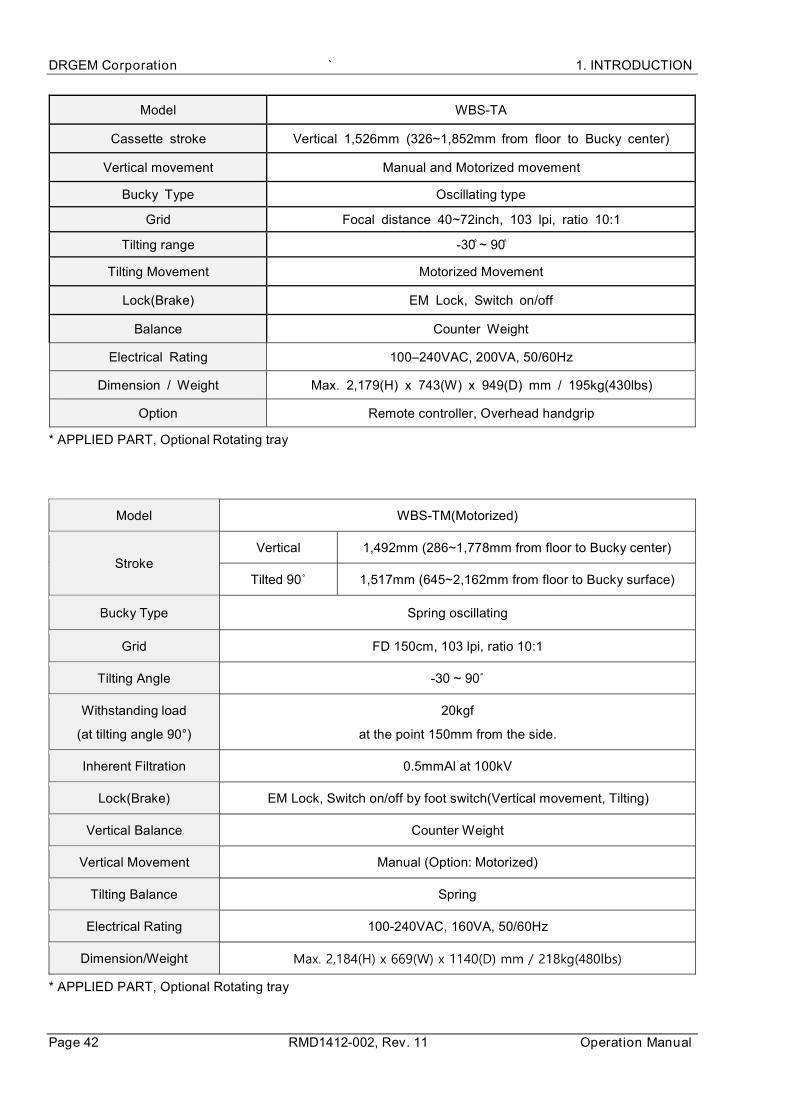
Model WBS-TA
Cassette stroke Vertical 1,526mm (326~1,852mm from floor to Bucky center)
Vertical movement Manual and Motorized movement
Bucky Type Oscillating type
Grid Focal distance 40~72inch, 103 lpi, ratio 10:1
Tilting range -
Tilting Movement Motorized Movement
Lock(Brake) EM Lock, Switch on/off
Balance Counter Weight
Electrical Rating 100–240VAC, 200VA, 50/60Hz
Dimension / Weight Max. 2,179(H) x 743(W) x 949(D) mm / 195kg(430lbs)
Option Remote controller, Overhead handgrip
* APPLIED PART, Optional Rotating tray
Model WBS-TM(Motorized)
Stroke Vertical 1,492mm (286~1,778mm from floor to Bucky center)
1,517mm (645~2,162mm from floor to Bucky surface)
Bucky Type Spring oscillating
Grid FD 150cm, 103 lpi, ratio 10:1
Tilting Angle -
Withstanding load
(at tilting angle 90°)
20kgf
at the point 150mm from the side.
Inherent Filtration 0.5mmAl at 100kV
Lock(Brake) EM Lock, Switch on/off by foot switch(Vertical movement, Tilting)
Vertical Balance Counter Weight
Vertical Movement Manual (Option: Motorized)
Tilting Balance Spring
Electrical Rating 100-240VAC, 160VA, 50/60Hz
Dimension/Weight
* APPLIED PART, Optional Rotating tray

1. INTRODUCTION GXR-SD/CSD/USD PREMIUM
Service Manual RMD1412-002, Rev.11 Page 43
Tube stand
1) Floor-Ceiling Mounted
Model TS-FC6(Motorized)
Tube Rotation Angle Horizontal axis ±135°
Vertical axis ±180° (mechanical detents at every 90°)
Tube stroke
Longitudinal 2,536mm
Lateral 220mm
Vertical 1,526mm (440~1,966mm from floor to focus)
Vertical Movement Manual or Motorized(Option)
Motorized option supports vertical sync with table and wall stand
Tube Rotation Manual or Motorized(Option)
Motorized option supports the source tilting type image stitching operation
Lock(Brake) EM Lock, Switch on/off
Balance Counter Weight
Column Rotation 90° step, Foot Lock
Options Line laser, Column rotation by electrical release
Electrical Rating 100–240VAC, 160VA, 50/60Hz
Dimension / Weight 2,465(H) x 3,600(W) x 1,420(D) mm / 240kg(529lbs)
Option(Tube Head Motorized Rotation) : 2458(H)x1140(D)mm /260kg(571lbs)
Model TS-FC4(Motorized)
Tube Rotation Angle ±135°
Tube stroke
Longitudinal 2,036mm / 2,536mm
Lateral N/A
Vertical 1,410mm (420~1,830mm from floor to focus)
1,660mm (420~2,080mm from floor to focus)
Vertical Movement Manual and Motorized movement
Lock(Brake) EM Lock, Switch on/off
Balance Counter Weight
Electrical Rating 100–240VAC, 160VA, 50/60Hz
Dimension / Weight Max. 3,600(W) x 780(D) x 2,050(H)mm / 172kg(378lbs)

DRGEM Corporation ` 1. INTRODUCTION
Page 44 RMD1412-002, Rev. 11 Operation Manual
Model TS-FC2(Motorized)
Tube Direction Right-angle or Straight
Tube Rotation N/A
Tube stroke
Longitudinal N/A
Lateral N/A
Vertical
1) 1,080mm(324mm~1,404mm from floor to focus)
2) 1,230mm(324mm~1,554mm from floor to focus)
3) 1,400mm(324mm~1,724mm from floor to focus)
4) 1,650mm(324mm~1,974mm from floor to focus)
Vertical Movement Motorized, Vertical synchronization with wall stand
Lock(Brake) EM Lock, Switch on/off
Balance Counter Weight
Electrical Rating 100–240VAC, 160VA, 50/60Hz
Dimension / Weight 1) Right-angle type: 1,614(H) x 659 (W) x 770(D) mm / 162kg(357lbs)
Straight type: 1,614(H) x 659 (W) x 859(D) mm / 162kg(357lbs)
2) Right-angle type: 1,764(H) x 659 (W) x 770(D) mm / 165kg(363lbs)
Straight type: 1,764(H) x 659 (W) x 859(D) mm / 165kg(363lbs)
3) Right-angle type: 1,934(H) x 659(W) x 770(D) mm / 155kg(341lbs)
Straight type: 1,934(H) x 659(W) x 859(D) mm / 155kg(341lbs)
4) Right-angle type: 2,184(H) x 659(W) x 770(D) mm / 160kg(352lbs)
Straight type: 2,184(H) x 659(W) x 859(D) mm / 160kg(352lbs)

1. INTRODUCTION GXR-SD/CSD/USD PREMIUM
Service Manual RMD1412-002, Rev.11 Page 45
2) Floor Mounted
Model TS-FM6(Motorized)
Tube Rotation Angle Horizontal axis ±135°
Vertical axis ±180° (mechanical detents at every 90°)
Tube stroke
Longitudinal 2,100mm
(Optional 2,900mm and 3,600mm)
Lateral 250mm
Vertical 1,526mm (420~1,946mm from floor to focus)
Vertical Movement Manual or Motorized(Option)
Motorized option supports vertical sync with table and wall stand
Tube Rotation Manual or Motorized(Option)
Motorized option supports the source tilting type image stitching operation
Lock(Brake) EM Lock, Switch on/off
Balance Counter Weight
Column Rotation EM lock, Switch on/off
Tube OP 7 inch Touch screen
Electrical Rating 100–240VAC, 160VA, 50/60Hz
Dimension / Weight
2,327(H) x 3,006(D) mm / 262kg(578lbs)
Option(Tube Head Motorized Rotation): 2,330(H) x 3,006(D) mm
/272kg(599lbs)

DRGEM Corporation ` 1. INTRODUCTION
Page 46 RMD1412-002, Rev. 11 Operation Manual
3) Ceiling suspended
Model TS-CSA
Tube Rotation Angle Horizontal axis ±180° (LCD display)
Vertical axis ±180° (mechanical detents at every 90°)
Tube stroke
(with 3x4m rails -
Transverse x Longitudinal)
Longitudinal 3,280mm(with 4m rail), 4,280mm(with 5m rail)
Lateral 2,200mm(with 3m rail), 3,200mm(with 4m rail)
Vertical
1,500mm or 1,600mm
(1,500mm is possible up to the weight of
E7252X plus R108)
Lock(Brake) EM Lock, Switch on/off
Balance Spring
Vertical Movement Manual or Motorized(Option)
Motorized option supports vertical sync with table and wall stand
Tube Rotation Manual or Motorized(Option)
Motorized option supports the source tilting type image stitching operation
Option Auto Collimation, Detent
SID Indication 7inch Touch Screen LCD with control buttons
Electrical Rating 100–240VAC, 200VA, 50/60Hz
Dimension 2,830(H) x 3,000(D) mm x 4,000(W) mm
when vertical direction is fully extended with 1,600mm stroke and 3x4m rails
Weight Main body: 170kg(375lbs) except tube and collimator,
Rails: 115kg(254lbs, 3x4m rails)

1. INTRODUCTION GXR-SD/CSD/USD PREMIUM
Service Manual RMD1412-002, Rev.11 Page 47
Model TS-CSP
Tube Rotation Angle Horizontal axis ±180° (LCD display)
Vertical axis ±180° (mechanical detents at every 90°)
Tube stroke
(with 3x4m rails -
Transverse x
Longitudinal)
Longitudinal 3,280mm
Lateral 2,200mm
Vertical 1,600mm
Lock(Brake) EM Lock, Switch on/off
Balance Spring
Operation Manual or Vertical Motorized
Optional vertical synchronization with Wall stand and Table for motorized stand
Indication / Control 7inch Touch Screen LCD with control buttons
Dimension 2758(mm)x3000(mm)x4000(mm)
Electrical Rating 220-230V~, 500VA, 50/60Hz
Weight Main body: 175kg(386lbs) except tube, Rails: 122kg(269lbs)

DRGEM Corporation ` 1. INTRODUCTION
Page 48 RMD1412-002, Rev. 11 Operation Manual
X-ray Tube
Tube Model E7239X DXT-8M E7242X DXT-11M
Manufacturer CANON DRGEM CANON DRGEM
Focal Spot Size 1.0/2.0mm 1.0/2.0mm 0.6/1.5mm 0.6/1.5mm
Rating(0.1s) 22.5/47kW@60Hz 22.5/47kW@60Hz 18/50kW@60Hz 18/50kW@60Hz
Max. Anode HU 140kHU(100kJ) 140kHU(100kJ) 200kHU(142kJ) 200kHU(142kJ)
Target Angle 16° 16° 14° 14°
Max. kV 125kV 125kV 125kV 125kV
Weight 16kg(35.3lbs) 16kg(35.3lbs) 16kg(35.3lbs) 16kg(35.3lbs)
Inherent Filtration 0.9mmAl/75kV 1.0mmAl/75kV 0.9mmAl/75kV 1.0mmAl/75kV
Half Value Layer More than 2.9mmAl eq. at 80kVp
Leakage
Radiation
Less than 100mR/hr
Tube Model E7843X DXT-10M E7876X
Manufacturer CANON DRGEM CANON
Focal Spot Size 0.6/1.2mm 0.6/1.2mm 0.6/1.2mm
Rating(0.1s) 22/50kW@60Hz 17/48kW@60Hz 22/54kW@60Hz
Max. Anode HU 150kHU(111kJ) 150kHU(111kJ) 230kHU(163kJ)
Target Angle 12° 12° 12°
Max. kV 150kV 125kV 150kV
Weight 16kg(35.3lbs) 16kg(35.3lbs) 16kg(55.1lbs)
Inherent Filtration 1.3mmAl/75kV 1.0mmAl/75kV 1.3mmAl/75kV
Half Value Layer More than 2.9mmAl eq. at 80kVp
Leakage Radiation Less than 100mR/hr

1. INTRODUCTION GXR-SD/CSD/USD PREMIUM
Service Manual RMD1412-002, Rev.11 Page 49
Tube Model E7884X DXT-12M E7252X
Manufacturer CANON DRGEM CANON
Focal Spot Size 0.6/1.2mm 0.6/1.2mm 0.6/1.2mm
Rating(0.1s) 22/54kW@60Hz 22/54kW@60Hz 27/75kW
Max. Anode HU 300kHU(210kJ) 300kHU(210kJ) 300kHU(210kJ)
Target Angle 12° 12° 12°
Max. kV 150kV 150kV 150kV
Weight 16kg(35.3lbs) 16kg(35.3lbs) 18kg(39.7lbs)
Inherent Filtration 0.9mmAl/75kV 1.0mmAl/75kV 0.9mmAl/75kV
Half Value Layer More than 2.9mmAl eq. at 80kVp
Leakage Radiation Less than 100mR/hr
Tube Model DXT-14U RAD-14 DXT-15U *
Manufacturer DRGEM VAREX DRGEM
Focal Spot Size 0.6/1.2mm 0.6/1.2mm 0.6/1.2mm
Rating(0.1s) 27/75kW 32/77kW 32/77kW
Max. Anode HU 300kHU(210kJ) 300kHU(210kJ) 300kHU(210kJ)
Target Angle 12° 12° 12°
Max. kV 150kV 150kV 150kV
Weight 18kg(39.7lbs) 16.4kg(36.2lbs) 16.4kg(36.2lbs)
Inherent Filtration 1.0mmAl/75kV 0.6mmAl/75kV 0.7mmAl/75kV
Additional Filtration 0.5mmAl 0.5mmAl
Half Value Layer More than 2.9mmAl eq. at 80kVp
Leakage Radiation Less than 100mR/hr
* Adopting VAREX RAD-14 Insert.

DRGEM Corporation ` 1. INTRODUCTION
Page 50 RMD1412-002, Rev. 11 Operation Manual
Tube Model RAD-21 RAD-60 RAD-92
Manufacturer VAREX VAREX VAREX
Focal Spot Size 0.6/1.2mm 0.6/1.2mm 0.6/1.2mm
Rating(0.1s) 36/100kW 40/100kW 40/100kW
Max. Anode HU 300kHU(210kJ) 400kHU(285kJ) 600kHU(444kJ)
Target Angle 12° 12° 12°
Max. kV 150kV 150kV 150kV
Weight 18.9kg(41.7lbs) 18.9kg(41.7lbs) 18.9kg(41.7lbs)
Inherent Filtration 0.7mmAl/75kV 0.7mmAl/75kV 0.7mmAl/75kV
Additional Filtration 0.5mmAl
Half Value Layer More than 2.9mmAl eq. at 80kVp
Leakage Radiation Less than 100mR/hr
Tube Model E7255FX E7254FX E7869X
Manufacturer CANON CANON CANON
Focal Spot Size 0.6/1.2mm 0.6/1.2mm 0.6/1.2mm
Rating(0.1s) 40/102kW 40/102kW 40/100kW
Max. Anode HU 300kHU(210kJ) 400kHU(285kJ) 600kHU(444kJ)
Target Angle 12° 12° 12°
Max. kV 150kV 150kV 150kV
Weight 20kg(44.1lbs) 25kg(55.1lbs) 24kg(52.9lbs)
Inherent Filtration 0.8mmAl/75kV 0.8mmAl/75kV 1.1mmAl/75kV
Additional Filtration 0.5mmAl
Half Value Layer More than 2.9mmAl eq. at 80kVp
Leakage Radiation Less than 100mR/hr
* Total filtration including X-ray tube assembly and collimator will be matched by appropriate additional filters
to within the range from 2.9 to 3.2mmAl. eq.

1. INTRODUCTION GXR-SD/CSD/USD PREMIUM
Service Manual RMD1412-002, Rev.11 Page 51
Collimator
Model MCR DXC-RML, DXC-RMH
Manufacturer DRGEM
Control Manual with 30sec. lamp timer
Field Shape Rectangular
Max. Field Size More than 43x43cm(17x17inch) at 100cm SID
Leakage Radiation Less than 100mR/hr Less than 40 mR/h
Max. kVp shield 150kV 150kV
Inherent Filtration 1.2mmAl eq. 2mmAl eq.
Luminosity Over 160LUX at 100cm SID (Typ.
200LUX) Over 160LUX at 1cm SID
Light source HLX64642 150W 24V
/ OSRAM LED and Halogen
Standard Rotating flange with fixing knob
Option Tape measure
Line laser+shutter, Measure tape
Near port moving shutters,
Mounting flange mechanical detent
Accessory guides spring,
Additional filter, DAP rail
Electrical Rating 24Vac, 6.3A, 50/60Hz
Halogen type - 24 V DC/AC - 50~60Hz
160VA
LED type - 12~45V DC 35VA / 20~30VAC
35VA - 50~60Hz
Dimension / Weight 185(W) x 213(D) x 180(H) mm /
6.3kg(13.9lb)
196(W) x 250(D) x 171(H) mm
7.1kg(15.6lb)

DRGEM Corporation ` 1. INTRODUCTION
Page 52 RMD1412-002, Rev. 11 Operation Manual
Model R108 R302A, R302MLP/A, R302MFMLP/A
Manufacturer RALCO
Control Manual with 30sec. lamp timer
Field Shape Rectangular
Max. Field Size More than 43x43cm(17x17inch) at 100cm SID
Leakage Radiation Less than 100mR/hr
Max. kVp shield 150kV 150kV
Inherent Filtration 2.0mmAl eq. 2.0mmAl eq.
Luminosity Over 160LUX at 100cm SID (Typ.
250LUX)
Over 160LUX at 100cm SID (Typ.
200LUX)
Light source Single LED HLX64638 100W 24V
/ OSRAM
Standard Tape measure,
rotating flange
Auto collimation for R302 MLP/A and R
302 MFMLP/A
Auto filter selection for R 302 MFMLP/A
Option Line laser,
near port shutters Tape measure, line laser, rotating flange
Electrical Rating 20–30Vac, 30VA, 50/60Hz 24Vac, 6.3A, 50/60Hz
Dimension / Weight 223(W) x 246(D) x 140(H) mm /
6.6kg(14.6lb)
195.5(W) x 237(D) x 206.5(H) mm /
9.4kg(20.7lb)
AEC Ion Chamber (Option)
Model ICX1162(ICX1192B) Amplimat 5-Field
Manufacturer AID Philips
Field 3 Fields 5 Fields
X-ray Energy Range 40~150kV 40~150kV
Exposure time Range 1ms to 10s 1ms to 6s
Inherent Filtration 0.4 mm Al eq. 0.8 mm Al eq.
Weight 2kg (4.4lb) 1.8kg (4lb)

1. INTRODUCTION GXR-SD/CSD/USD PREMIUM
Service Manual RMD1412-002, Rev.11 Page 53
DAP meter (Option)
DAP Resolution
Interface RS485
Active area 115 x 115mm / 146 x 146mm
Display Optional integrated or separate display (single or dual line)
Dimension 158 x 134.5 x 17mm / 180 x 156 x 17mm
Other Options
Pedestal console stand
Patient holder
Patient hand grips (Tabletop, Wall stand – Overhead, Lateral)
Cassette holders (Lateral, External Wall Bucky)
DAP meter with display
Full-spine imaging software with apparatus
DC power supply for line powered x-ray generator in case of insufficient line power
DC brake for low speed starter of x-ray generator
Radiation protection
Wearing(apron, neck guide, glove), movable x-ray protection wall
AP (Access Point) for Wireless
Model RT-AC68U (AC 1900)
Product Picture
Manufacturer ASUS
Standards IEEE 802.11n, IEEE 802.11ac
Frequency 5GHz / 2.4GHz
Wireless LAN (max.) 1.3Gbps(5GHz)/600Mbps (2.4GHz)
Weight Antennas Type
AC Power Adapter 19V / 1.75A
Regulatory Compliance CE, FCC, RoHS, KCC

DRGEM Corporation ` 1. INTRODUCTION
Page 54 RMD1412-002, Rev. 11 Operation Manual
Software Version

1. INTRODUCTION GXR-SD/CSD/USD PREMIUM
Service Manual RMD1412-002, Rev.11 Page 55
OPERATING ENVIRONMENT
Ambient temperature range 10 to 40 C (50 to 105 F).
Relative humidity 30% to 75%, non-condensing
Atmospheric pressure range 700 hPa to 1060 hPa
This product is rated to operate at an altitude 3000m
TRANSPORT AND STORAGE ENVIRONMENT
Ambient temperature range -10 to 70 C (14 to 158 F).
Relative humidity 10 to 90%, non-condensing.
Atmospheric pressure range 500 hPa to 1060 hPa
Do not operate this system except in accordance with information included in
this section, and any additional information provided by the manufacturer and
/ or competent safety authorities.