beverly tourer 250ie
TRANSCRIPT
PIAGGIO WOULD LIKE TO THANK YOU
for choosing one of its products. We have prepared this manual to help you to get the very best from your scooter. Please read it carefully before ridingthe scooter for the first time. It contains information, tips and precautions for using your scooter. It also describes features, details and devices to assureyou that you have made the right choice. We believe that if you follow our suggestions, you will soon get to know your new vehicle and it will serve youwell for a long time to come. This booklet forms an integral part of the scooter; should the scooter be sold, it must be transferred to the new owner.
Beverly Tourer 250ie
The instructions given in this manual are intended to provide a clear, simple guide to using your scooter; this booklet also details routine maintenanceprocedures and regular checks that should be carried out on the vehicle at an authorised Dealer or Service Centre. The booklet also containsinstructions for simple repairs. Any operations not specifically described in this manual require the use of special tools and/or particular technicalknowledge: to carry out these operations refer to any authorised Dealer of Service Centres.
2
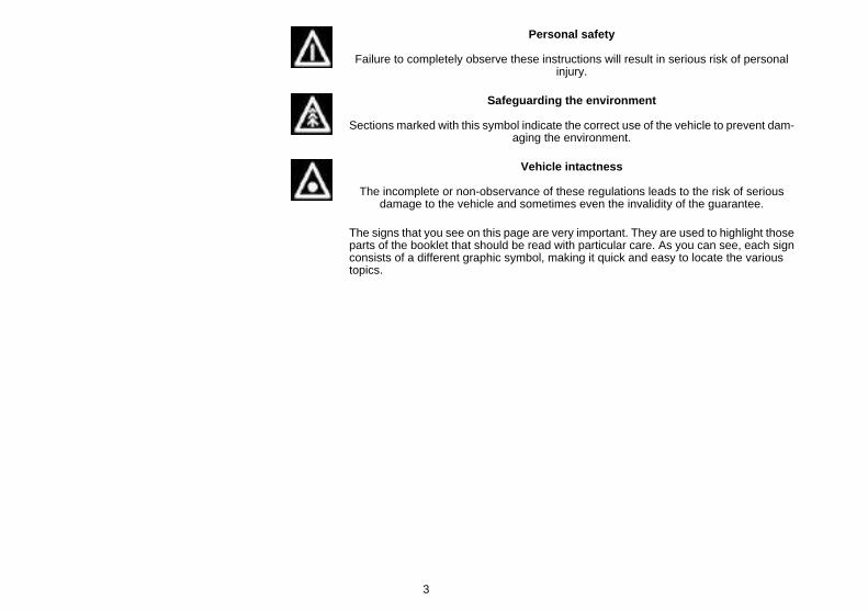
Personal safety
Failure to completely observe these instructions will result in serious risk of personalinjury.
Safeguarding the environment
Sections marked with this symbol indicate the correct use of the vehicle to prevent dam-aging the environment.
Vehicle intactness
The incomplete or non-observance of these regulations leads to the risk of seriousdamage to the vehicle and sometimes even the invalidity of the guarantee.
The signs that you see on this page are very important. They are used to highlight thoseparts of the booklet that should be read with particular care. As you can see, each signconsists of a different graphic symbol, making it quick and easy to locate the varioustopics.
3

4
INDEX
VEHICLE...................................................................................... 7Dashboard................................................................................ 9Analogue instrument panel....................................................... 11Clock......................................................................................... 12Key switch................................................................................. 12
Locking the steering wheel.................................................... 12Releasing the steering wheel................................................ 12
Switch direction indicators........................................................ 13Horn button............................................................................... 13Light switch............................................................................... 13Start-up button.......................................................................... 14Engine stop button.................................................................... 14The immobilizer system............................................................ 14
Keys...................................................................................... 14Immobilizerdevice enabled indicator led............................... 15Operation............................................................................... 15Programming the immobilizer system................................... 16
Accessing the fuel tank............................................................. 18Power supply socket................................................................. 18The saddle................................................................................ 19
Opening the saddle............................................................... 19Identification.............................................................................. 20Rear top box opening................................................................ 21Bag clip..................................................................................... 22
USE.............................................................................................. 23Checks...................................................................................... 24Refuelling.................................................................................. 24Tyre pressure............................................................................ 25Shock absorbers adjustment.................................................... 27Running in................................................................................. 28Starting up the engine............................................................... 28Stopping the engine.................................................................. 29anello antifurto.......................................................................... 30
Stand......................................................................................... 30Automatic transmission............................................................. 31Safe driving............................................................................... 32
MAINTENANCE........................................................................... 35Engine oil level.......................................................................... 36
Engine oil level check............................................................ 36Engine oil top-up................................................................... 36Warning light (insufficient oil pressure)................................. 36Engine oil change.................................................................. 37
Hub oil level.............................................................................. 38Tyres......................................................................................... 40Spark plug dismantlement........................................................ 42Removing the air filter............................................................... 43Air filter cleaning....................................................................... 43Cooling fluid level...................................................................... 44Checking the brake oil level...................................................... 46
Braking system fluid top up................................................... 46Battery....................................................................................... 47
Use of a new battery............................................................. 48Long periods of inactivity.......................................................... 48Fuses........................................................................................ 49Lamps....................................................................................... 52Front light group........................................................................ 54
Headlight adjustment............................................................. 54Front direction indicators........................................................... 56Rear optical unit........................................................................ 56Number plate light..................................................................... 58Helmet compartment lighting bulb............................................ 58Rear-view mirrors...................................................................... 59Front and rear disc brake.......................................................... 59Puncture.................................................................................... 60Periods of inactivity................................................................... 61Cleaning the vehicle.................................................................. 61
5
Troubleshooting........................................................................ 62TECHNICAL DATA...................................................................... 67
Kit equipment............................................................................ 72SPARE PARTS AND ACCESSORIES........................................ 73
Warnings................................................................................... 74PROGRAMMED MAINTENANCE............................................... 77
Scheduled maintenance table................................................... 78
6
BeverlyTourer 250ie
Chap. 01Vehicle
7
01_01
8
1 V
ehic
le
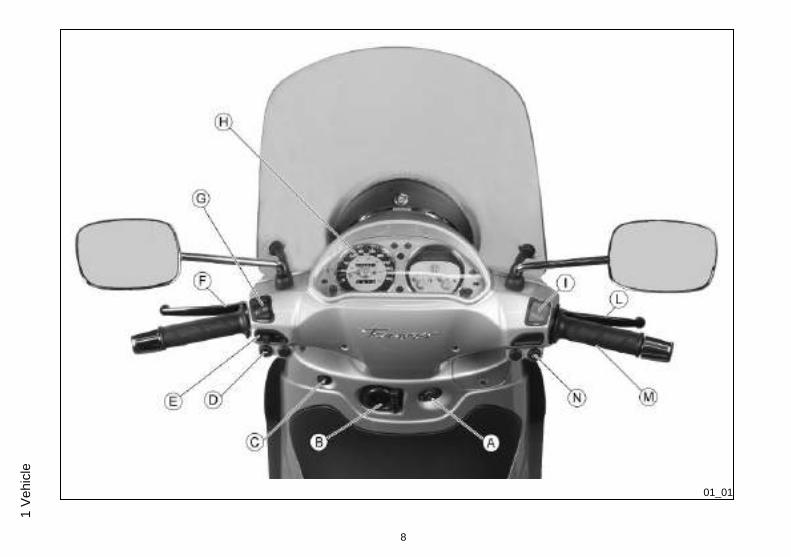
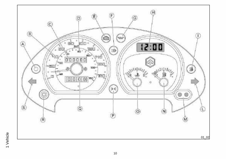
Dashboard (01_01)
A = Ignition key-switch
B = Bag hook
C = Saddle electric opening switch
D = Horn button
E = Turn indicator switch
F = Rear brake control lever
G = Light switch with passing
H = Instrument panel
I = Emergency cut-off switch RUN/OFF
L = Front brake lever
M = Throttle grip
N = Starter button
9
1 Vehicle
01_02
10
1 V
ehic
le
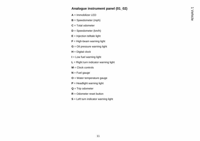
Analogue instrument panel (01_02)
A = Immobilizer LED
B = Speedometer (mph)
C = Total odometer
D = Speedometer (km/h)
E = Injection telltale light
F = High-beam warning light
G = Oil pressure warning light
H = Digital clock
I = Low fuel warning light
L = Right turn indicator warning light
M = Clock controls
N = Fuel gauge
O = Water temperature gauge
P = Headlight warning light
Q = Trip odometer
R = Odometer reset button
S = Left turn indicator warning light
11
1 Vehicle
01_03
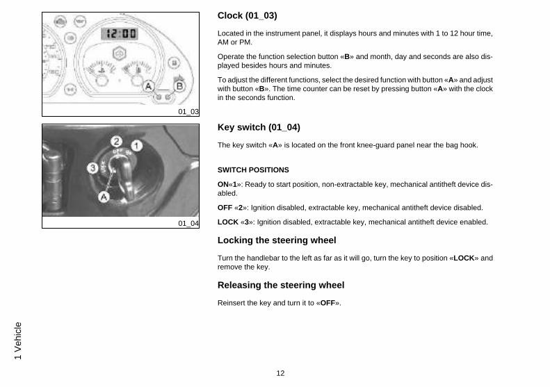
Clock (01_03)
Located in the instrument panel, it displays hours and minutes with 1 to 12 hour time,AM or PM.
Operate the function selection button «B» and month, day and seconds are also dis-played besides hours and minutes.
To adjust the different functions, select the desired function with button «A» and adjustwith button «B». The time counter can be reset by pressing button «A» with the clockin the seconds function.
01_04
Key switch (01_04)
The key switch «A» is located on the front knee-guard panel near the bag hook.
SWITCH POSITIONS
ON«1»: Ready to start position, non-extractable key, mechanical antitheft device dis-abled.
OFF «2»: Ignition disabled, extractable key, mechanical antitheft device disabled.
LOCK «3»: Ignition disabled, extractable key, mechanical antitheft device enabled.
Locking the steering wheel
Turn the handlebar to the left as far as it will go, turn the key to position «LOCK» andremove the key.
Releasing the steering wheel
Reinsert the key and turn it to «OFF».
12
1 V
ehic
le
01_05
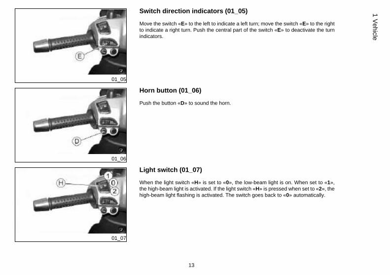
Switch direction indicators (01_05)
Move the switch «E» to the left to indicate a left turn; move the switch «E» to the rightto indicate a right turn. Push the central part of the switch «E» to deactivate the turnindicators.
01_06
Horn button (01_06)
Push the button «D» to sound the horn.
01_07
Light switch (01_07)
When the light switch «H» is set to «0», the low-beam light is on. When set to «1»,the high-beam light is activated. If the light switch «H» is pressed when set to «2», thehigh-beam light flashing is activated. The switch goes back to «0» automatically.
13
1 Vehicle
01_08
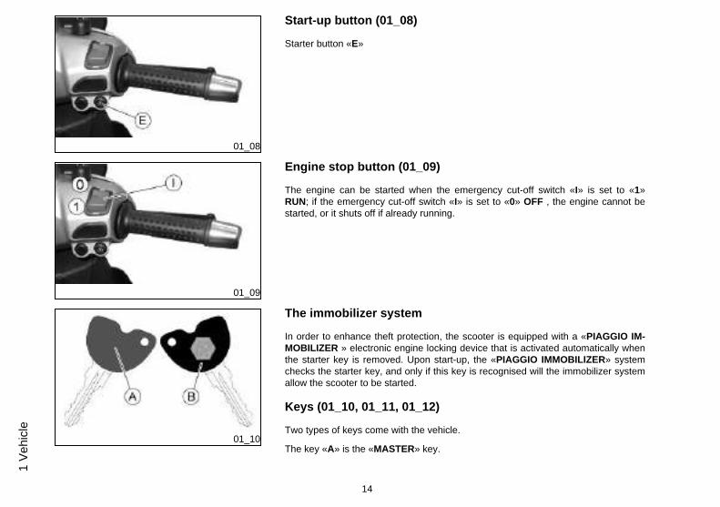
Start-up button (01_08)
Starter button «E»
01_09
Engine stop button (01_09)
The engine can be started when the emergency cut-off switch «I» is set to «1»RUN; if the emergency cut-off switch «I» is set to «0» OFF , the engine cannot bestarted, or it shuts off if already running.
01_10
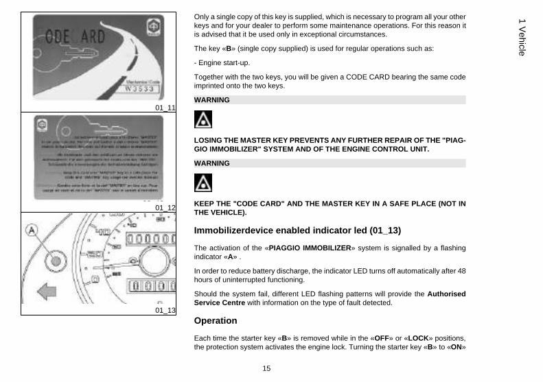
The immobilizer system
In order to enhance theft protection, the scooter is equipped with a «PIAGGIO IM-MOBILIZER » electronic engine locking device that is activated automatically whenthe starter key is removed. Upon start-up, the «PIAGGIO IMMOBILIZER» systemchecks the starter key, and only if this key is recognised will the immobilizer systemallow the scooter to be started.
Keys (01_10, 01_11, 01_12)
Two types of keys come with the vehicle.
The key «A» is the «MASTER» key.
14
1 V
ehic
le
01_11
01_12
01_13
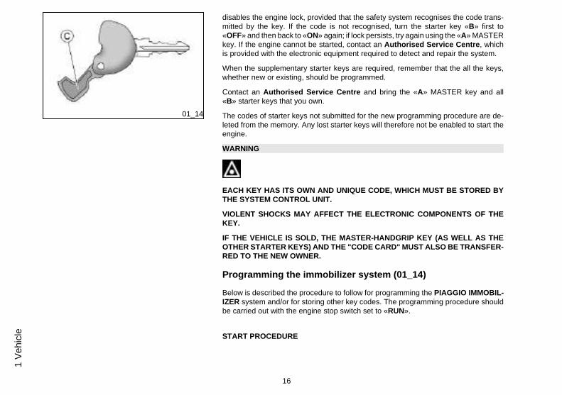
Only a single copy of this key is supplied, which is necessary to program all your otherkeys and for your dealer to perform some maintenance operations. For this reason itis advised that it be used only in exceptional circumstances.
The key «B» (single copy supplied) is used for regular operations such as:
- Engine start-up.
Together with the two keys, you will be given a CODE CARD bearing the same codeimprinted onto the two keys.
WARNING
LOSING THE MASTER KEY PREVENTS ANY FURTHER REPAIR OF THE "PIAG-GIO IMMOBILIZER" SYSTEM AND OF THE ENGINE CONTROL UNIT.
WARNING
KEEP THE "CODE CARD" AND THE MASTER KEY IN A SAFE PLACE (NOT INTHE VEHICLE).
Immobilizerdevice enabled indicator led (01_13)
The activation of the «PIAGGIO IMMOBILIZER» system is signalled by a flashingindicator «A» .
In order to reduce battery discharge, the indicator LED turns off automatically after 48hours of uninterrupted functioning.
Should the system fail, different LED flashing patterns will provide the AuthorisedService Centre with information on the type of fault detected.
Operation
Each time the starter key «B» is removed while in the «OFF» or «LOCK» positions,the protection system activates the engine lock. Turning the starter key «B» to «ON»
15
1 Vehicle
01_14
disables the engine lock, provided that the safety system recognises the code trans-mitted by the key. If the code is not recognised, turn the starter key «B» first to«OFF» and then back to «ON» again; if lock persists, try again using the «A» MASTERkey. If the engine cannot be started, contact an Authorised Service Centre, whichis provided with the electronic equipment required to detect and repair the system.
When the supplementary starter keys are required, remember that the all the keys,whether new or existing, should be programmed.
Contact an Authorised Service Centre and bring the «A» MASTER key and all«B» starter keys that you own.
The codes of starter keys not submitted for the new programming procedure are de-leted from the memory. Any lost starter keys will therefore not be enabled to start theengine.
WARNING
EACH KEY HAS ITS OWN AND UNIQUE CODE, WHICH MUST BE STORED BYTHE SYSTEM CONTROL UNIT.
VIOLENT SHOCKS MAY AFFECT THE ELECTRONIC COMPONENTS OF THEKEY.
IF THE VEHICLE IS SOLD, THE MASTER-HANDGRIP KEY (AS WELL AS THEOTHER STARTER KEYS) AND THE "CODE CARD" MUST ALSO BE TRANSFER-RED TO THE NEW OWNER.
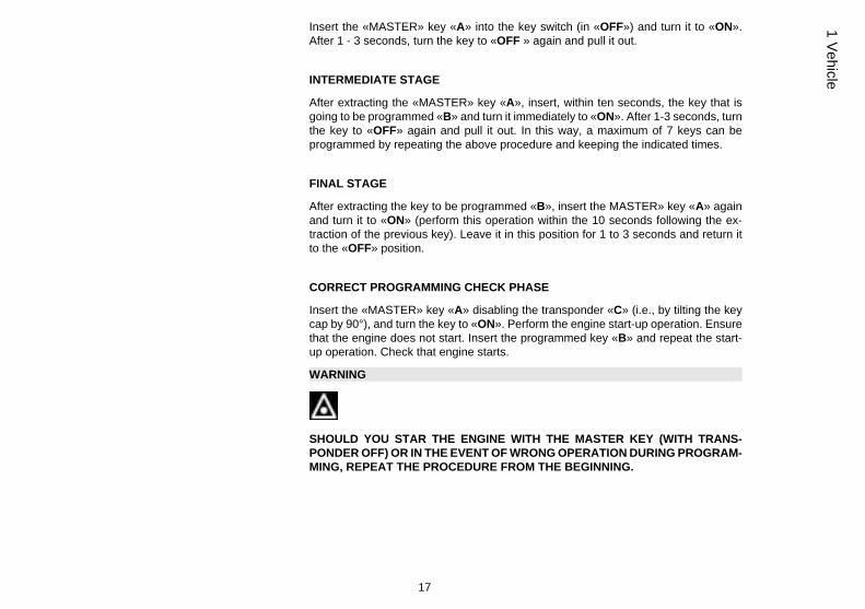
Programming the immobilizer system (01_14)
Below is described the procedure to follow for programming the PIAGGIO IMMOBIL-IZER system and/or for storing other key codes. The programming procedure shouldbe carried out with the engine stop switch set to «RUN».
START PROCEDURE
16
1 V
ehic
le
Insert the «MASTER» key «A» into the key switch (in «OFF») and turn it to «ON».After 1 - 3 seconds, turn the key to «OFF » again and pull it out.
INTERMEDIATE STAGE
After extracting the «MASTER» key «A», insert, within ten seconds, the key that isgoing to be programmed «B» and turn it immediately to «ON». After 1-3 seconds, turnthe key to «OFF» again and pull it out. In this way, a maximum of 7 keys can beprogrammed by repeating the above procedure and keeping the indicated times.
FINAL STAGE
After extracting the key to be programmed «B», insert the MASTER» key «A» againand turn it to «ON» (perform this operation within the 10 seconds following the ex-traction of the previous key). Leave it in this position for 1 to 3 seconds and return itto the «OFF» position.
CORRECT PROGRAMMING CHECK PHASE
Insert the «MASTER» key «A» disabling the transponder «C» (i.e., by tilting the keycap by 90°), and turn the key to «ON». Perform the engine start-up operation. Ensurethat the engine does not start. Insert the programmed key «B» and repeat the start-up operation. Check that engine starts.
WARNING
SHOULD YOU STAR THE ENGINE WITH THE MASTER KEY (WITH TRANS-PONDER OFF) OR IN THE EVENT OF WRONG OPERATION DURING PROGRAM-MING, REPEAT THE PROCEDURE FROM THE BEGINNING.
17
1 Vehicle
01_15
01_16
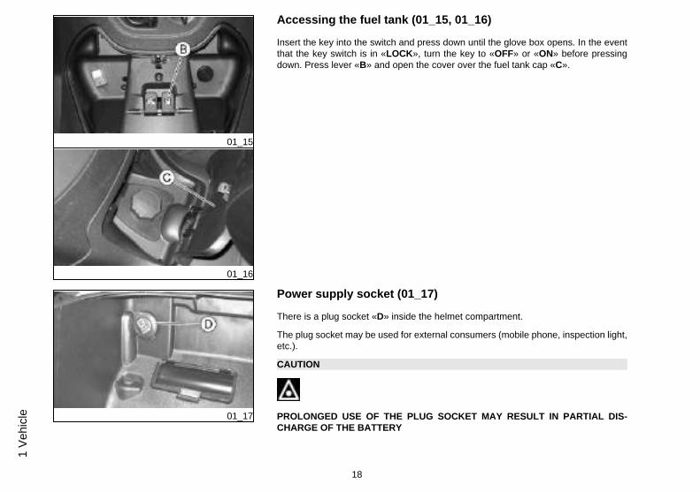
Accessing the fuel tank (01_15, 01_16)
Insert the key into the switch and press down until the glove box opens. In the eventthat the key switch is in «LOCK», turn the key to «OFF» or «ON» before pressingdown. Press lever «B» and open the cover over the fuel tank cap «C».
01_17
Power supply socket (01_17)
There is a plug socket «D» inside the helmet compartment.
The plug socket may be used for external consumers (mobile phone, inspection light,etc.).
CAUTION
PROLONGED USE OF THE PLUG SOCKET MAY RESULT IN PARTIAL DIS-CHARGE OF THE BATTERY
18
1 V
ehic
le
Electric characteristic
Plug socket
12 V - 180 W MAX
01_18
01_19
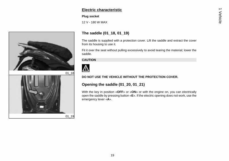
The saddle (01_18, 01_19)
The saddle is supplied with a protection cover. Lift the saddle and extract the coverfrom its housing to use it.
Fit it over the seat without pulling excessively to avoid tearing the material; lower thesaddle.
CAUTION
DO NOT USE THE VEHICLE WITHOUT THE PROTECTION COVER.
Opening the saddle (01_20, 01_21)
With the key in position «OFF» or «ON» or with the engine on, you can electricallyopen the saddle by pressing button «E». If the electric opening does not work, use theemergency lever «A».
19
1 Vehicle
01_20
01_21
01_22
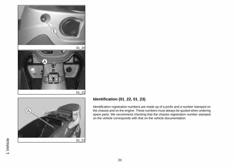
Identification (01_22, 01_23)
Identification registration numbers are made up of a prefix and a number stamped onthe chassis and on the engine. These numbers must always be quoted when orderingspare parts. We recommend checking that the chassis registration number stampedon the vehicle corresponds with that on the vehicle documentation.
20
1 V
ehic
le
01_23
CAUTION
BE REMINDED THAT ALTERING IDENTIFICATION REGISTRATION NUMBERSCAN LEAD TO SERIOUS PENAL SANCTIONS (IMPOUNDING OF THE VEHICLE,ETC.).
Chassis number
To read the chassis number, remove the lid «A» in the helmet compartment.
Engine number
The engine number «B» is stamped near the rear left shock absorber lower support.
01_24
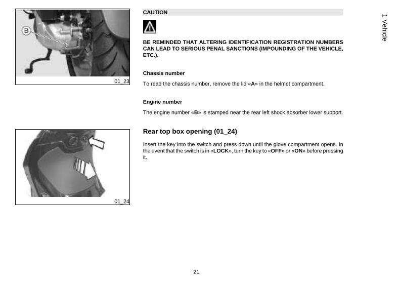
Rear top box opening (01_24)
Insert the key into the switch and press down until the glove compartment opens. Inthe event that the switch is in «LOCK», turn the key to «OFF» or «ON» before pressingit.
21
1 Vehicle
01_25
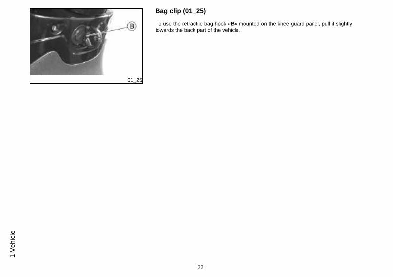
Bag clip (01_25)
To use the retractile bag hook «B» mounted on the knee-guard panel, pull it slightlytowards the back part of the vehicle.
22
1 V
ehic
le
BeverlyTourer 250ie
Chap. 02Use
23
02_01
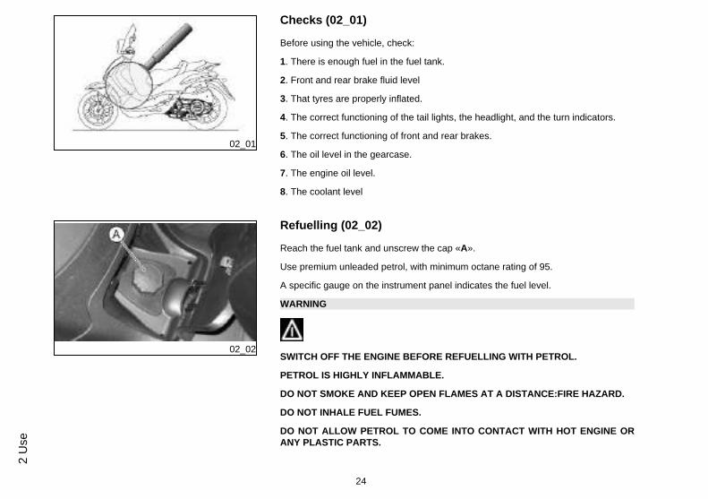
Checks (02_01)
Before using the vehicle, check:
1. There is enough fuel in the fuel tank.
2. Front and rear brake fluid level
3. That tyres are properly inflated.
4. The correct functioning of the tail lights, the headlight, and the turn indicators.
5. The correct functioning of front and rear brakes.
6. The oil level in the gearcase.
7. The engine oil level.
8. The coolant level
02_02
Refuelling (02_02)
Reach the fuel tank and unscrew the cap «A».
Use premium unleaded petrol, with minimum octane rating of 95.
A specific gauge on the instrument panel indicates the fuel level.
WARNING
SWITCH OFF THE ENGINE BEFORE REFUELLING WITH PETROL.
PETROL IS HIGHLY INFLAMMABLE.
DO NOT SMOKE AND KEEP OPEN FLAMES AT A DISTANCE:FIRE HAZARD.
DO NOT INHALE FUEL FUMES.
DO NOT ALLOW PETROL TO COME INTO CONTACT WITH HOT ENGINE ORANY PLASTIC PARTS.
24
2 U
se
CAUTION
PETROL DAMAGES THE PLASTIC PARTS OF THE BODYWORK.
CAUTION
DO NOT USE THE VEHICLE TO THE COMPLETE EXHAUSTION OF THE FUEL;IN THE EVENT THAT THIS SHOULD OCCUR, DO NOT ATTEMPT TO START THEENGINE. TURN THE KEY SWITCH TO OFF AND TOP-UP THE TANK AS SOONAS POSSIBLE. FAILURE TO FOLLOW THESE GUIDELINES COULD DAMAGETHE FUEL PUMP AND/OR THE CATALYTIC CONVERTER.
Characteristic
Fuel tank (reserve)
~ 10 l (2 l)
02_03
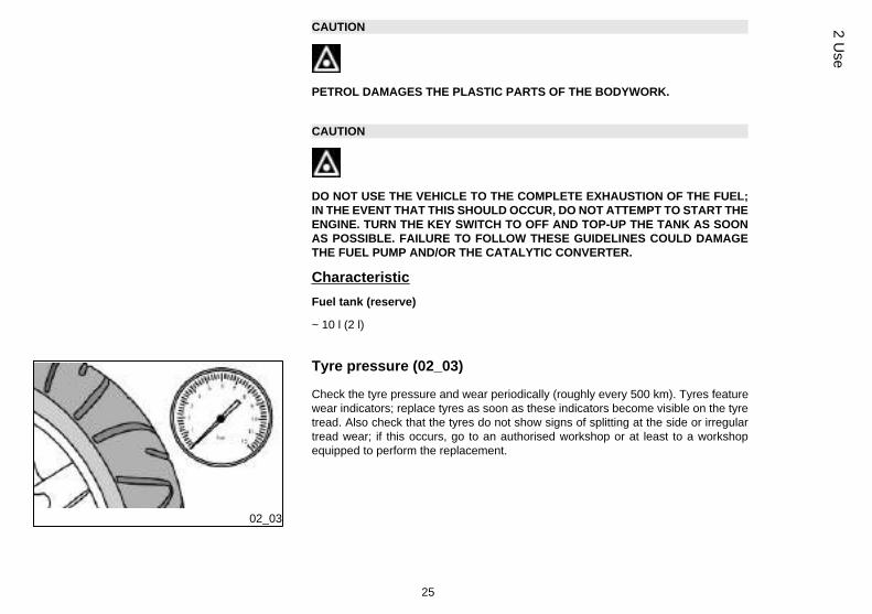
Tyre pressure (02_03)
Check the tyre pressure and wear periodically (roughly every 500 km). Tyres featurewear indicators; replace tyres as soon as these indicators become visible on the tyretread. Also check that the tyres do not show signs of splitting at the side or irregulartread wear; if this occurs, go to an authorised workshop or at least to a workshopequipped to perform the replacement.
25
2 Use
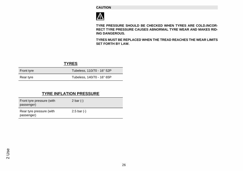
CAUTION
TYRE PRESSURE SHOULD BE CHECKED WHEN TYRES ARE COLD.INCOR-RECT TYRE PRESSURE CAUSES ABNORMAL TYRE WEAR AND MAKES RID-ING DANGEROUS.
TYRES MUST BE REPLACED WHEN THE TREAD REACHES THE WEAR LIMITSSET FORTH BY LAW.
TYRES
Front tyre Tubeless, 110/70 - 16'' 52P
Rear tyre Tubeless, 140/70 - 16'' 65P
TYRE INFLATION PRESSURE
Front tyre pressure (withpassenger)
2 bar (-)
Rear tyre pressure (withpassenger)
2.5 bar (-)
26
2 U
se
02_04
02_05
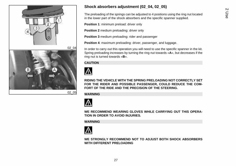
Shock absorbers adjustment (02_04, 02_05)
The preloading of the springs can be adjusted to 4 positions using the ring nut locatedin the lower part of the shock absorbers and the specific spanner supplied.
Position 1: minimum preload: driver only
Position 2 medium preloading: driver only
Position 3 medium preloading: rider and passenger
Position 4: maximum preloading: driver, passenger, and luggage.
In order to carry out this operation you will need to use the specific spanner in the kit.Spring preloading increases by turning the ring nut towards «A», but decreases if thering nut is turned towards «B».
CAUTION
RIDING THE VEHICLE WITH THE SPRING PRELOADING NOT CORRECTLY SETFOR THE RIDER AND POSSIBLE PASSENGER, COULD REDUCE THE COM-FORT OF THE RIDE AND THE PRECISION OF THE STEERING.
WARNING
WE RECOMMEND WEARING GLOVES WHILE CARRYING OUT THIS OPERA-TION IN ORDER TO AVOID INJURIES.
WARNING
WE STRONGLY RECOMMEND NOT TO ADJUST BOTH SHOCK ABSORBERSWITH DIFFERENT PRELOADING
27
2 Use
02_06
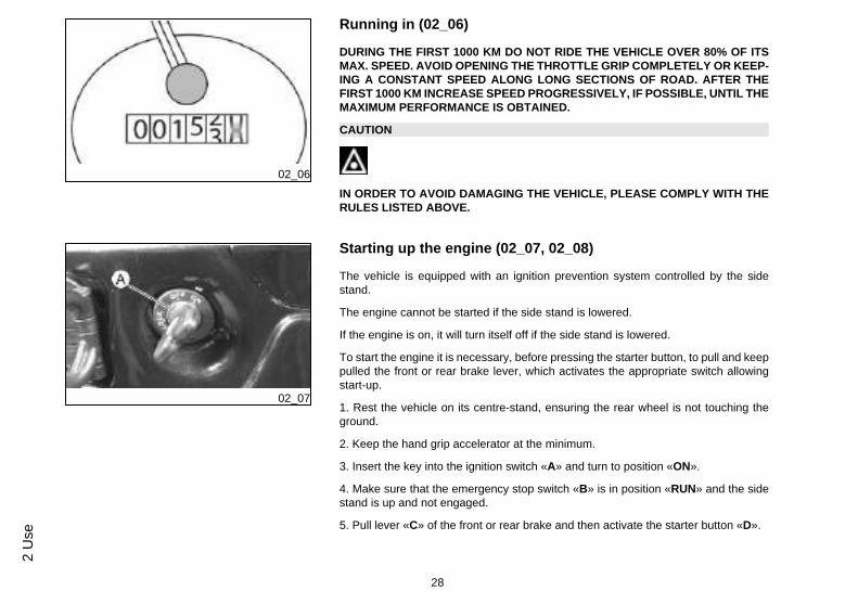
Running in (02_06)
DURING THE FIRST 1000 KM DO NOT RIDE THE VEHICLE OVER 80% OF ITSMAX. SPEED. AVOID OPENING THE THROTTLE GRIP COMPLETELY OR KEEP-ING A CONSTANT SPEED ALONG LONG SECTIONS OF ROAD. AFTER THEFIRST 1000 KM INCREASE SPEED PROGRESSIVELY, IF POSSIBLE, UNTIL THEMAXIMUM PERFORMANCE IS OBTAINED.
CAUTION
IN ORDER TO AVOID DAMAGING THE VEHICLE, PLEASE COMPLY WITH THERULES LISTED ABOVE.
02_07
Starting up the engine (02_07, 02_08)
The vehicle is equipped with an ignition prevention system controlled by the sidestand.
The engine cannot be started if the side stand is lowered.
If the engine is on, it will turn itself off if the side stand is lowered.
To start the engine it is necessary, before pressing the starter button, to pull and keeppulled the front or rear brake lever, which activates the appropriate switch allowingstart-up.
1. Rest the vehicle on its centre-stand, ensuring the rear wheel is not touching theground.
2. Keep the hand grip accelerator at the minimum.
3. Insert the key into the ignition switch «A» and turn to position «ON».
4. Make sure that the emergency stop switch «B» is in position «RUN» and the sidestand is up and not engaged.
5. Pull lever «C» of the front or rear brake and then activate the starter button «D».
28
2 U
se
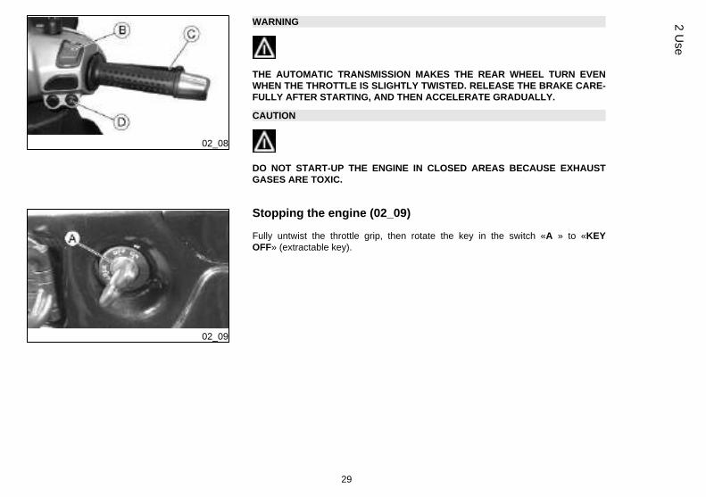
02_08
WARNING
THE AUTOMATIC TRANSMISSION MAKES THE REAR WHEEL TURN EVENWHEN THE THROTTLE IS SLIGHTLY TWISTED. RELEASE THE BRAKE CARE-FULLY AFTER STARTING, AND THEN ACCELERATE GRADUALLY.
CAUTION
DO NOT START-UP THE ENGINE IN CLOSED AREAS BECAUSE EXHAUSTGASES ARE TOXIC.
02_09
Stopping the engine (02_09)
Fully untwist the throttle grip, then rotate the key in the switch «A » to «KEYOFF» (extractable key).
29
2 Use
02_10
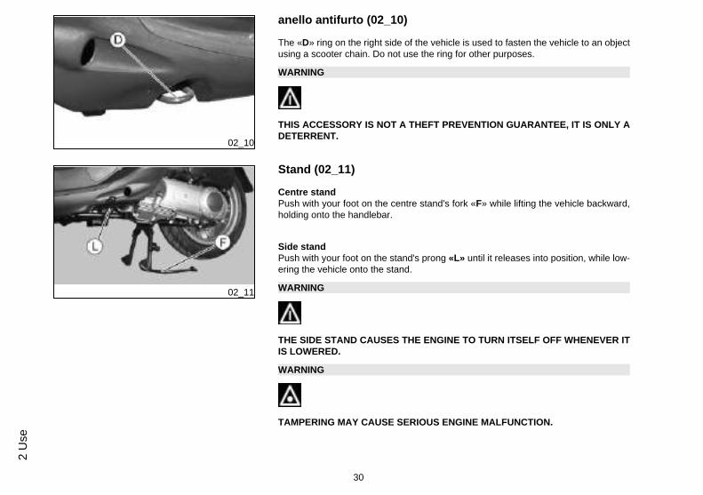
anello antifurto (02_10)
The «D» ring on the right side of the vehicle is used to fasten the vehicle to an objectusing a scooter chain. Do not use the ring for other purposes.
WARNING
THIS ACCESSORY IS NOT A THEFT PREVENTION GUARANTEE, IT IS ONLY ADETERRENT.
02_11
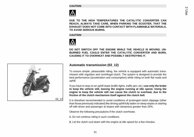
Stand (02_11)
Centre standPush with your foot on the centre stand's fork «F» while lifting the vehicle backward,holding onto the handlebar.
Side standPush with your foot on the stand's prong «L» until it releases into position, while low-ering the vehicle onto the stand.
WARNING
THE SIDE STAND CAUSES THE ENGINE TO TURN ITSELF OFF WHENEVER ITIS LOWERED.
WARNING
TAMPERING MAY CAUSE SERIOUS ENGINE MALFUNCTION.
30
2 U
se
CAUTION
DUE TO THE HIGH TEMPERATURES THE CATALYTIC CONVERTER CANREACH, ALWAYS TAKE CARE, WHEN PARKING THE SCOOTER, THAT THEEXHAUST DOES NOT COME INTO CONTACT WITH FLAMMABLE MATERIALS,TO AVOID SERIOUS BURNS.
CAUTION
DO NOT SWITCH OFF THE ENGINE WHILE THE VEHICLE IS MOVING. UN-BURNED FUEL COULD ENTER THE CATALYTIC CONVERTER AND BURN,CAUSING IT TO OVERHEAT AND POSSIBLY DESTROYING IT.
02_12
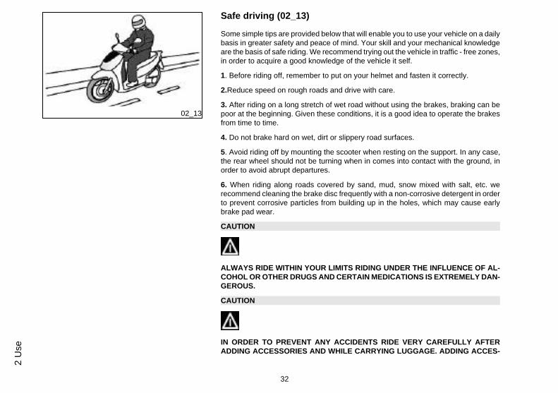
Automatic transmission (02_12)
To ensure simple, pleasurable riding, the vehicle is equipped with automatic trans-mission with regulator and centrifugal clutch. The system is designed to provide thebest performance (acceleration and consumption) while riding on both flat roads anduphill.
If you have to stop on an uphill slope (traffic lights, traffic jam, etc.) use only the braketo keep the vehicle still, leaving the engine running at idle speed. Using theengine to keep the vehicle still can cause the clutch to overheat, due to thefriction of the clutch mechanism itself against the clutch bell.
It is therefore recommended to avoid conditions of prolonged clutch slippage (otherthan those previously indicated) like driving uphill fully laden on steep slopes or startingoff with driver and passenger at slopes with steepness greater than 25%.
Observe the following precautions if the clutch overheats:
1. Do not continue riding in such conditions.
2. Let the clutch cool down with the engine at idle speed for a few minutes.
31
2 Use
02_13
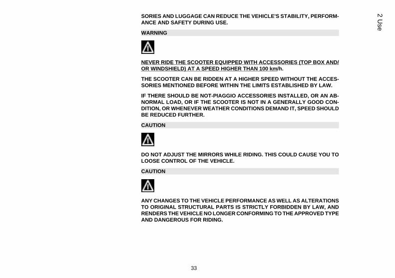
Safe driving (02_13)
Some simple tips are provided below that will enable you to use your vehicle on a dailybasis in greater safety and peace of mind. Your skill and your mechanical knowledgeare the basis of safe riding. We recommend trying out the vehicle in traffic - free zones,in order to acquire a good knowledge of the vehicle it self.
1. Before riding off, remember to put on your helmet and fasten it correctly.
2.Reduce speed on rough roads and drive with care.
3. After riding on a long stretch of wet road without using the brakes, braking can bepoor at the beginning. Given these conditions, it is a good idea to operate the brakesfrom time to time.
4. Do not brake hard on wet, dirt or slippery road surfaces.
5. Avoid riding off by mounting the scooter when resting on the support. In any case,the rear wheel should not be turning when in comes into contact with the ground, inorder to avoid abrupt departures.
6. When riding along roads covered by sand, mud, snow mixed with salt, etc. werecommend cleaning the brake disc frequently with a non-corrosive detergent in orderto prevent corrosive particles from building up in the holes, which may cause earlybrake pad wear.
CAUTION
ALWAYS RIDE WITHIN YOUR LIMITS RIDING UNDER THE INFLUENCE OF AL-COHOL OR OTHER DRUGS AND CERTAIN MEDICATIONS IS EXTREMELY DAN-GEROUS.
CAUTION
IN ORDER TO PREVENT ANY ACCIDENTS RIDE VERY CAREFULLY AFTERADDING ACCESSORIES AND WHILE CARRYING LUGGAGE. ADDING ACCES-
32
2 U
se
SORIES AND LUGGAGE CAN REDUCE THE VEHICLE'S STABILITY, PERFORM-ANCE AND SAFETY DURING USE.
WARNING
NEVER RIDE THE SCOOTER EQUIPPED WITH ACCESSORIES (TOP BOX AND/OR WINDSHIELD) AT A SPEED HIGHER THAN 100 km/h.
THE SCOOTER CAN BE RIDDEN AT A HIGHER SPEED WITHOUT THE ACCES-SORIES MENTIONED BEFORE WITHIN THE LIMITS ESTABLISHED BY LAW.
IF THERE SHOULD BE NOT-PIAGGIO ACCESSORIES INSTALLED, OR AN AB-NORMAL LOAD, OR IF THE SCOOTER IS NOT IN A GENERALLY GOOD CON-DITION, OR WHENEVER WEATHER CONDITIONS DEMAND IT, SPEED SHOULDBE REDUCED FURTHER.
CAUTION
DO NOT ADJUST THE MIRRORS WHILE RIDING. THIS COULD CAUSE YOU TOLOOSE CONTROL OF THE VEHICLE.
CAUTION
ANY CHANGES TO THE VEHICLE PERFORMANCE AS WELL AS ALTERATIONSTO ORIGINAL STRUCTURAL PARTS IS STRICTLY FORBIDDEN BY LAW, ANDRENDERS THE VEHICLE NO LONGER CONFORMING TO THE APPROVED TYPEAND DANGEROUS FOR RIDING.
33
2 Use

34
2 U
se
BeverlyTourer 250ie
Chap. 03Maintenance
35
03_01
03_02
03_03
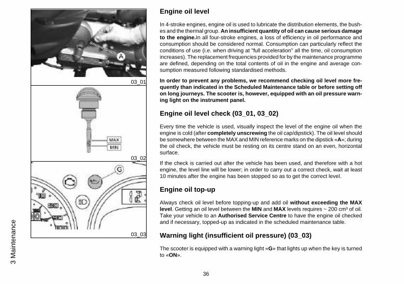
Engine oil level
In 4-stroke engines, engine oil is used to lubricate the distribution elements, the bush-es and the thermal group. An insufficient quantity of oil can cause serious damageto the engine.In all four-stroke engines, a loss of efficiency in oil performance andconsumption should be considered normal. Consumption can particularly reflect theconditions of use (i.e. when driving at "full acceleration" all the time, oil consumptionincreases). The replacement frequencies provided for by the maintenance programmeare defined, depending on the total contents of oil in the engine and average con-sumption measured following standardised methods.
In order to prevent any problems, we recommend checking oil level more fre-quently than indicated in the Scheduled Maintenance table or before setting offon long journeys. The scooter is, however, equipped with an oil pressure warn-ing light on the instrument panel.
Engine oil level check (03_01, 03_02)
Every time the vehicle is used, visually inspect the level of the engine oil when theengine is cold (after completely unscrewing the oil cap/dipstick). The oil level shouldbe somewhere between the MAX and MIN reference marks on the dipstick «A»; duringthe oil check, the vehicle must be resting on its centre stand on an even, horizontalsurface.
If the check is carried out after the vehicle has been used, and therefore with a hotengine, the level line will be lower; in order to carry out a correct check, wait at least10 minutes after the engine has been stopped so as to get the correct level.
Engine oil top-up
Always check oil level before topping-up and add oil without exceeding the MAXlevel. Getting an oil level between the MIN and MAX levels requires ~ 200 cm³ of oil.Take your vehicle to an Authorised Service Centre to have the engine oil checkedand if necessary, topped-up as indicated in the scheduled maintenance table.
Warning light (insufficient oil pressure) (03_03)
The scooter is equipped with a warning light «G» that lights up when the key is turnedto «ON».
36
3 M
aint
enan
ce
03_04
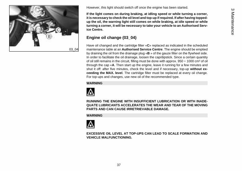
However, this light should switch off once the engine has been started.
If the light comes on during braking, at idling speed or while turning a corner,it is necessary to check the oil level and top-up if required. If after having topped-up the oil, the warning light still comes on while braking, at idle speed or whileturning a corner, it will be necessary to take your vehicle to an Authorised Serv-ice Centre.
Engine oil change (03_04)
Have oil changed and the cartridge filter «C» replaced as indicated in the scheduledmaintenance table at an Authorised Service Centre. The engine should be emptiedby draining the oil from the drainage plug «B » of the gauze filter on the flywheel side.In order to facilitate the oil drainage, loosen the cap/dipstick. Since a certain quantityof oil still remains in the circuit, filling must be done with approx. 950 ÷ 1000 cm³ of oilthrough the cap «A. Then start up the engine, leave it running for a few minutes andshut it off: after five minutes, check the level and if necessary, top-up without ex-ceeding the MAX. level. The cartridge filter must be replaced at every oil change.For top-ups and changes, use new oil of the recommended type.
WARNING
RUNNING THE ENGINE WITH INSUFFICIENT LUBRICATION OR WITH INADE-QUATE LUBRICANTS ACCELERATES THE WEAR AND TEAR OF THE MOVINGPARTS AND CAN CAUSE IRRETRIEVABLE DAMAGE.
WARNING
EXCESSIVE OIL LEVEL AT TOP-UPS CAN LEAD TO SCALE FORMATION ANDVEHICLE MALFUNCTIONING.
37
3 Maintenance
CAUTION
USED OILS CONTAIN SUBSTANCES HARMFUL TO THE ENVIRONMENT. FOROIL REPLACEMENT, CONTACT AN AUTHORISED PIAGGIO SERVICE CENTRE,AS THEY ARE EQUIPPED TO DISPOSE OF SPENT OILS IN AN ENVIRONMEN-TALLY FRIENDLY AND LEGAL WAY.
CAUTION
USING OILS OTHER THAN THOSE RECOMMENDED CAN SHORTEN THE LIFEOF THE ENGINE.
Recommended products
AGIP CITY HI TEC 4T
Engine oilSAE 5W-40, API SL, ACEA A3, JASO MA Synthetic oil
03_05
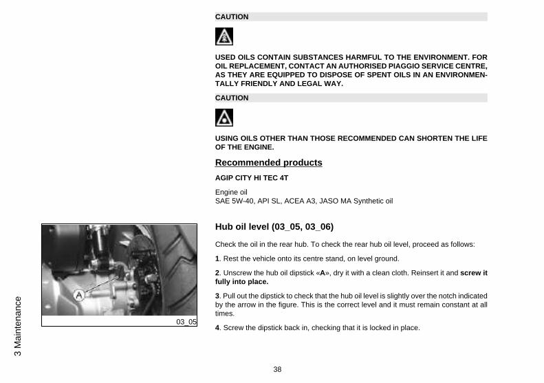
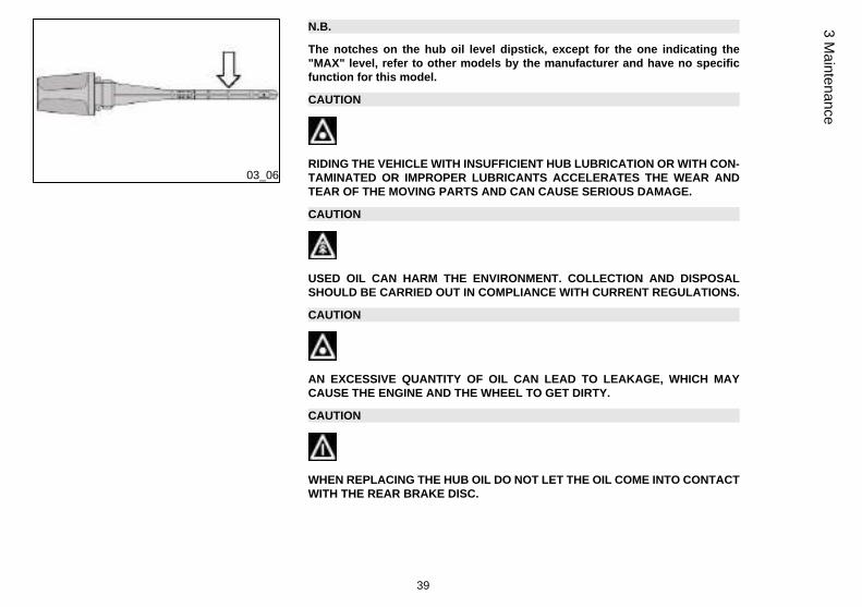
Hub oil level (03_05, 03_06)
Check the oil in the rear hub. To check the rear hub oil level, proceed as follows:
1. Rest the vehicle onto its centre stand, on level ground.
2. Unscrew the hub oil dipstick «A», dry it with a clean cloth. Reinsert it and screw itfully into place.
3. Pull out the dipstick to check that the hub oil level is slightly over the notch indicatedby the arrow in the figure. This is the correct level and it must remain constant at alltimes.
4. Screw the dipstick back in, checking that it is locked in place.
38
3 M
aint
enan
ce
03_06
N.B.
The notches on the hub oil level dipstick, except for the one indicating the"MAX" level, refer to other models by the manufacturer and have no specificfunction for this model.
CAUTION
RIDING THE VEHICLE WITH INSUFFICIENT HUB LUBRICATION OR WITH CON-TAMINATED OR IMPROPER LUBRICANTS ACCELERATES THE WEAR ANDTEAR OF THE MOVING PARTS AND CAN CAUSE SERIOUS DAMAGE.
CAUTION
USED OIL CAN HARM THE ENVIRONMENT. COLLECTION AND DISPOSALSHOULD BE CARRIED OUT IN COMPLIANCE WITH CURRENT REGULATIONS.
CAUTION
AN EXCESSIVE QUANTITY OF OIL CAN LEAD TO LEAKAGE, WHICH MAYCAUSE THE ENGINE AND THE WHEEL TO GET DIRTY.
CAUTION
WHEN REPLACING THE HUB OIL DO NOT LET THE OIL COME INTO CONTACTWITH THE REAR BRAKE DISC.
39
3 Maintenance
CAUTION
FOR OIL REPLACEMENT, CONTACT ANY AUTHORISED SERVICE CENTRE ASTHEY ARE EQUIPPED TO DISPOSE OF USED OILS IN AN ENVIRONMENTALLYFRIENDLY AND LEGAL WAY.
Recommended products
AGIP ROTRA 80W-90
Rear hub oilSAE 80W/90 Oil that exceeds the requirements of API GL3 specifications
Characteristic
Transmission oil
250 cm³
03_07
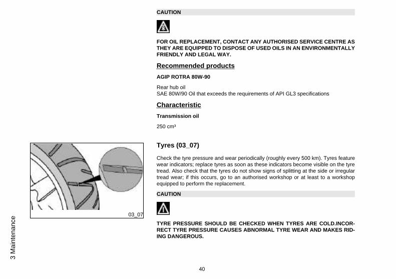
Tyres (03_07)
Check the tyre pressure and wear periodically (roughly every 500 km). Tyres featurewear indicators; replace tyres as soon as these indicators become visible on the tyretread. Also check that the tyres do not show signs of splitting at the side or irregulartread wear; if this occurs, go to an authorised workshop or at least to a workshopequipped to perform the replacement.
CAUTION
TYRE PRESSURE SHOULD BE CHECKED WHEN TYRES ARE COLD.INCOR-RECT TYRE PRESSURE CAUSES ABNORMAL TYRE WEAR AND MAKES RID-ING DANGEROUS.
40
3 M
aint
enan
ce
TYRES MUST BE REPLACED WHEN THE TREAD REACHES THE WEAR LIMITSSET FORTH BY LAW.
WARNING
THE WHEELS FITTED WITH TYRES SHOULD ALWAYS BE BALANCED. RIDINGTHE VEHICLE WITH VERY LOW TYRE PRESSURE OR WITH INCORRECTLYBALANCED TYRES CAN LEAD TO DANGEROUS STEERING VIBRATIONS.
TYRES
Front tyre Tubeless, 110/70 - 16'' 52P
Rear tyre Tubeless, 140/70 - 16'' 65P
TYRE INFLATION PRESSURE
Front tyre pressure (withpassenger)
2 bar (-)
Rear tyre pressure (withpassenger)
2.5 bar (-)
41
3 Maintenance
03_08
03_09
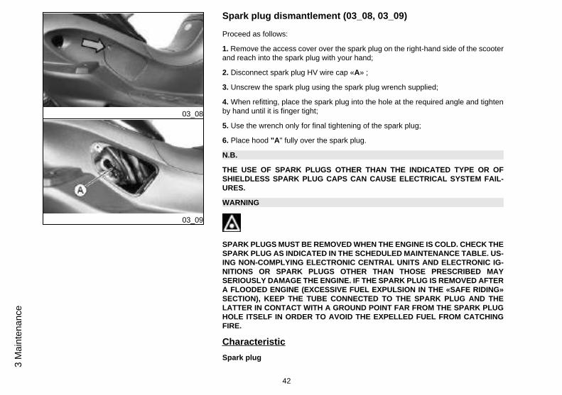
Spark plug dismantlement (03_08, 03_09)
Proceed as follows:
1. Remove the access cover over the spark plug on the right-hand side of the scooterand reach into the spark plug with your hand;
2. Disconnect spark plug HV wire cap «A» ;
3. Unscrew the spark plug using the spark plug wrench supplied;
4. When refitting, place the spark plug into the hole at the required angle and tightenby hand until it is finger tight;
5. Use the wrench only for final tightening of the spark plug;
6. Place hood "A" fully over the spark plug.
N.B.
THE USE OF SPARK PLUGS OTHER THAN THE INDICATED TYPE OR OFSHIELDLESS SPARK PLUG CAPS CAN CAUSE ELECTRICAL SYSTEM FAIL-URES.
WARNING
SPARK PLUGS MUST BE REMOVED WHEN THE ENGINE IS COLD. CHECK THESPARK PLUG AS INDICATED IN THE SCHEDULED MAINTENANCE TABLE. US-ING NON-COMPLYING ELECTRONIC CENTRAL UNITS AND ELECTRONIC IG-NITIONS OR SPARK PLUGS OTHER THAN THOSE PRESCRIBED MAYSERIOUSLY DAMAGE THE ENGINE. IF THE SPARK PLUG IS REMOVED AFTERA FLOODED ENGINE (EXCESSIVE FUEL EXPULSION IN THE «SAFE RIDING»SECTION), KEEP THE TUBE CONNECTED TO THE SPARK PLUG AND THELATTER IN CONTACT WITH A GROUND POINT FAR FROM THE SPARK PLUGHOLE ITSELF IN ORDER TO AVOID THE EXPELLED FUEL FROM CATCHINGFIRE.
Characteristic
Spark plug
42
3 M
aint
enan
ce
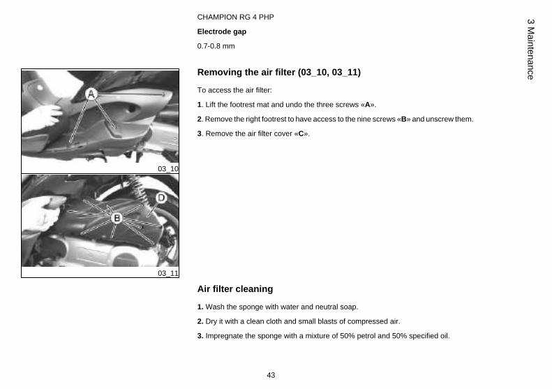
CHAMPION RG 4 PHP
Electrode gap
0.7-0.8 mm
03_10
03_11
Removing the air filter (03_10, 03_11)
To access the air filter:
1. Lift the footrest mat and undo the three screws «A».
2. Remove the right footrest to have access to the nine screws «B» and unscrew them.
3. Remove the air filter cover «C».
Air filter cleaning
1. Wash the sponge with water and neutral soap.
2. Dry it with a clean cloth and small blasts of compressed air.
3. Impregnate the sponge with a mixture of 50% petrol and 50% specified oil.
43
3 Maintenance
4. Gently squeeze the filter element, let it drip and then refit it.
CAUTION
IF THE VEHICLE IS USED ON DUSTY ROADS IT IS NECESSARY TO CARRY OUTMAINTENANCE CONTROLS OF THE AIR FILTER TO AVOID DAMAGING THEENGINE.
Recommended products
AGIP FILTER OIL
Oil for air filter spongeMineral oil with specific additives for increased adhesiveness
03_12
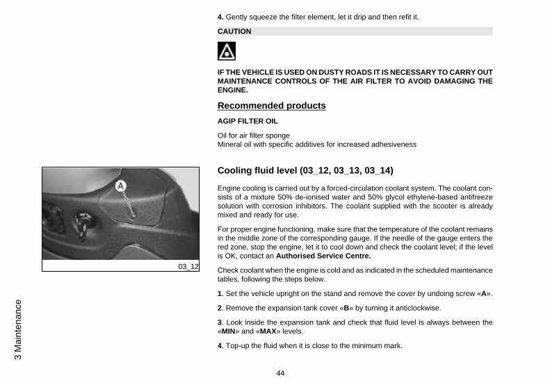
Cooling fluid level (03_12, 03_13, 03_14)
Engine cooling is carried out by a forced-circulation coolant system. The coolant con-sists of a mixture 50% de-ionised water and 50% glycol ethylene-based antifreezesolution with corrosion inhibitors. The coolant supplied with the scooter is alreadymixed and ready for use.
For proper engine functioning, make sure that the temperature of the coolant remainsin the middle zone of the corresponding gauge. If the needle of the gauge enters thered zone, stop the engine, let it to cool down and check the coolant level; if the levelis OK, contact an Authorised Service Centre.
Check coolant when the engine is cold and as indicated in the scheduled maintenancetables, following the steps below.
1. Set the vehicle upright on the stand and remove the cover by undoing screw «A».
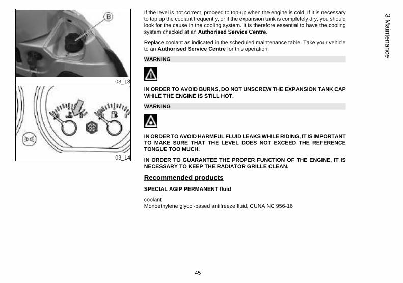
2. Remove the expansion tank cover «B» by turning it anticlockwise.
3. Look inside the expansion tank and check that fluid level is always between the«MIN» and «MAX» levels.
4. Top-up the fluid when it is close to the minimum mark.
44
3 M
aint
enan
ce
03_13
03_14
If the level is not correct, proceed to top-up when the engine is cold. If it is necessaryto top up the coolant frequently, or if the expansion tank is completely dry, you shouldlook for the cause in the cooling system. It is therefore essential to have the coolingsystem checked at an Authorised Service Centre.
Replace coolant as indicated in the scheduled maintenance table. Take your vehicleto an Authorised Service Centre for this operation.
WARNING
IN ORDER TO AVOID BURNS, DO NOT UNSCREW THE EXPANSION TANK CAPWHILE THE ENGINE IS STILL HOT.
WARNING
IN ORDER TO AVOID HARMFUL FLUID LEAKS WHILE RIDING, IT IS IMPORTANTTO MAKE SURE THAT THE LEVEL DOES NOT EXCEED THE REFERENCETONGUE TOO MUCH.
IN ORDER TO GUARANTEE THE PROPER FUNCTION OF THE ENGINE, IT ISNECESSARY TO KEEP THE RADIATOR GRILLE CLEAN.
Recommended products
SPECIAL AGIP PERMANENT fluid
coolantMonoethylene glycol-based antifreeze fluid, CUNA NC 956-16
45
3 Maintenance
03_15
03_16
03_17
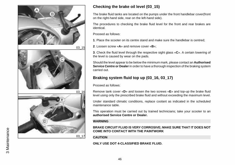
Checking the brake oil level (03_15)
The brake fluid tanks are located on the pumps under the front handlebar cover(fronton the right-hand side, rear on the left-hand side).
The procedures to checking the brake fluid level for the front and rear brakes areidentical.
Proceed as follows:
1. Place the scooter on its centre stand and make sure the handlebar is centred;
2. Loosen screw «A» and remove cover «B»;
3. Check the fluid level through the respective sight glass «C». A certain lowering ofthe level is caused by wear on the pads.
Should the level appear to be below the minimum mark, please contact an AuthorisedService Centre or Dealer in order to have a thorough inspection of the braking systemcarried out.
Braking system fluid top up (03_16, 03_17)
Proceed as follows:
Remove tank cover «D» and loosen the two screws «E» and top-up the brake fluidlevel using only the prescribed brake fluid and without exceeding the maximum level.
Under standard climatic conditions, replace coolant as indicated in the scheduledmaintenance table.
This operation must be carried out by trained technicians; take your scooter to anauthorised Service Centre or Dealer.
WARNING
BRAKE CIRCUIT FLUID IS VERY CORROSIVE; MAKE SURE THAT IT DOES NOTCOME INTO CONTACT WITH THE PAINTWORK
CAUTION
ONLY USE DOT 4-CLASSIFIED BRAKE FLUID.
46
3 M
aint
enan
ce
WARNING
THE BRAKE FLUID IS HAZARDOUS: IN CASE OF ACCIDENTAL CONTACT,WASH OFF WITH WATER.
WARNING
THE BRAKING CIRCUIT LIQUID IS HYGROSCOPIC, AND ABSORBS THE HU-MIDITY OF SURROUNDING AIR. IF THE HUMIDITY IN THE BRAKING FLUIDEXCEEDS A CERTAIN VALUE, IT WILL LEAD TO INEFFICIENT BRAKING. NEV-ER USE BRAKING FLUID KEPT IN CONTAINERS THAT HAVE ALREADY BEENOPENED, OR PARTIALLY USED.
Recommended products
AGIP BRAKE 4
Brake fluidFMVSS DOT 4 Synthetic fluid
03_18
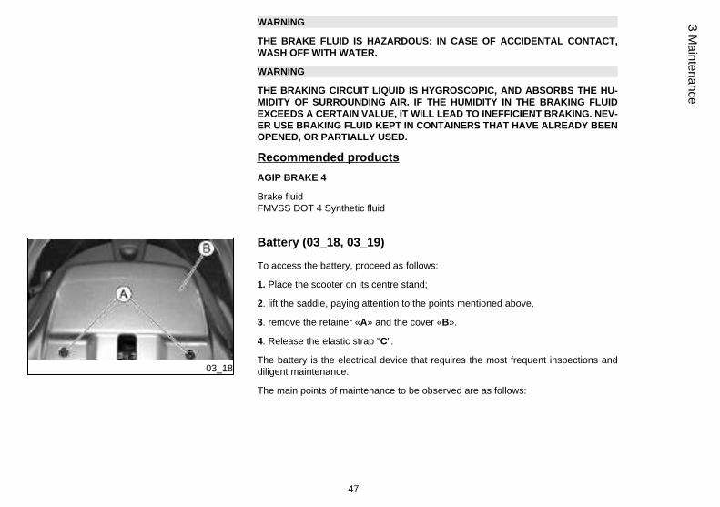
Battery (03_18, 03_19)
To access the battery, proceed as follows:
1. Place the scooter on its centre stand;
2. lift the saddle, paying attention to the points mentioned above.
3. remove the retainer «A» and the cover «B».
4. Release the elastic strap "C".
The battery is the electrical device that requires the most frequent inspections anddiligent maintenance.
The main points of maintenance to be observed are as follows:
47
3 Maintenance

03_19
WARNING
DO NOT DISCONNECT THE BATTERY CABLES WITH THE ENGINE RUNNING,THIS CAN CAUSE PERMANENT DAMAGE TO THE VEHICLE ELECTRONIC CON-TROL UNIT.
WARNING
SPENT BATTERIES ARE HARMFUL FOR THE ENVIRONMENT. COLLECTIONAND DISPOSAL SHOULD BE CARRIED OUT IN COMPLIANCE WITH CURRENTREGULATIONS.
Characteristic
Battery
12 V/12 Ah
Use of a new battery
Ensure that the terminals are connected correctly and check the voltage.
CAUTION
DO NOT REVERSE THE POLARITY: RISK OF SHORT CIRCUIT AND DAMAGETO THE ELECTRICAL SYSTEM.
Long periods of inactivity
Battery performance will decrease if the vehicle is not used for a long time. This is theresult of the natural phenomenon of battery discharging plus residual absorption by
48
3 M
aint
enan
ce
vehicle components with constant power consumption. Poor battery performance mayalso be due to environmental conditions and the cleanness of the poles. In order toavoid difficult starts and/or irreversible damage to the battery, follow any of thesesteps:
- At least once a month start the engine and run it slightly above idle speed for 10-15minutes. This keeps all the engine components, as well as the battery, in good workingorder.
- Take your vehicle to a garage (as indicated in the "Vehicle not used for extendedperiods" section) to have the battery removed. Have the battery cleaned, charged fullyand stored in a dry, ventilated place. Recharge at least once every two months.
CAUTION
THE BATTERY MUST BE RECHARGED WITH A CURRENT LOAD EQUAL TO 1/10OF THE BATTERY RATED CAPACITY AND FOR A PERIOD NOT LONGER THAN8 HOURS. TAKE THE VEHICLE TO AN AUTHORISED PIAGGIO SERVICE CEN-TRE FOR THIS OPERATION. WHEN REFITTING THE BATTERY MAKE SURE THELEADS ARE CORRECTLY CONNECTED TO THE TERMINALS.
03_20
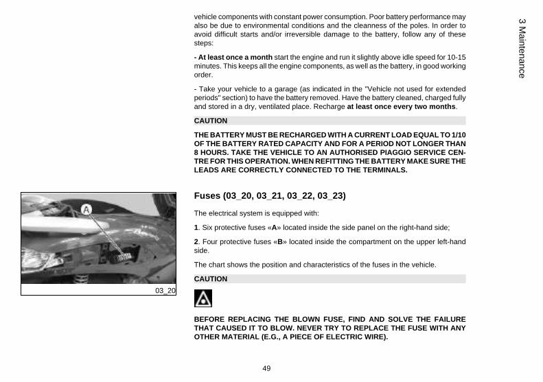
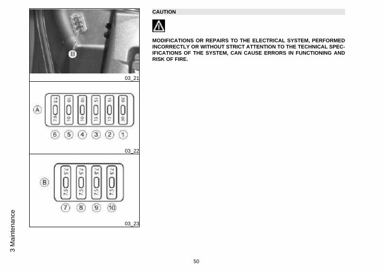
Fuses (03_20, 03_21, 03_22, 03_23)
The electrical system is equipped with:
1. Six protective fuses «A» located inside the side panel on the right-hand side;
2. Four protective fuses «B» located inside the compartment on the upper left-handside.
The chart shows the position and characteristics of the fuses in the vehicle.
CAUTION
BEFORE REPLACING THE BLOWN FUSE, FIND AND SOLVE THE FAILURETHAT CAUSED IT TO BLOW. NEVER TRY TO REPLACE THE FUSE WITH ANYOTHER MATERIAL (E.G., A PIECE OF ELECTRIC WIRE).
49
3 Maintenance
03_21
03_22
03_23
CAUTION
MODIFICATIONS OR REPAIRS TO THE ELECTRICAL SYSTEM, PERFORMEDINCORRECTLY OR WITHOUT STRICT ATTENTION TO THE TECHNICAL SPEC-IFICATIONS OF THE SYSTEM, CAN CAUSE ERRORS IN FUNCTIONING ANDRISK OF FIRE.
50
3 M
aint
enan
ce
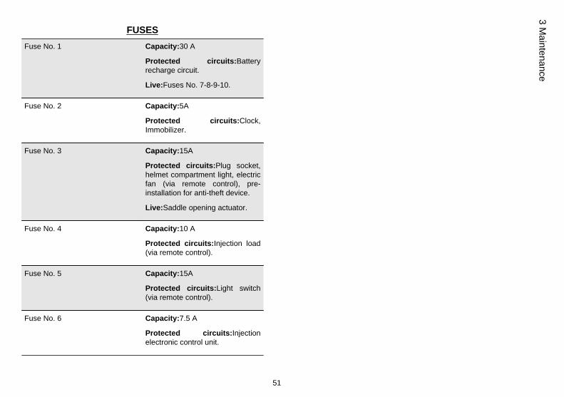
FUSES
Fuse No. 1 Capacity:30 A
Protected circuits:Batteryrecharge circuit.
Live:Fuses No. 7-8-9-10.
Fuse No. 2 Capacity:5A
Protected circuits:Clock,Immobilizer.
Fuse No. 3 Capacity:15A
Protected circuits:Plug socket,helmet compartment light, electricfan (via remote control), pre-installation for anti-theft device.
Live:Saddle opening actuator.
Fuse No. 4 Capacity:10 A
Protected circuits:Injection load(via remote control).
Fuse No. 5 Capacity:15A
Protected circuits:Light switch(via remote control).
Fuse No. 6 Capacity:7.5 A
Protected circuits:Injectionelectronic control unit.
51
3 Maintenance
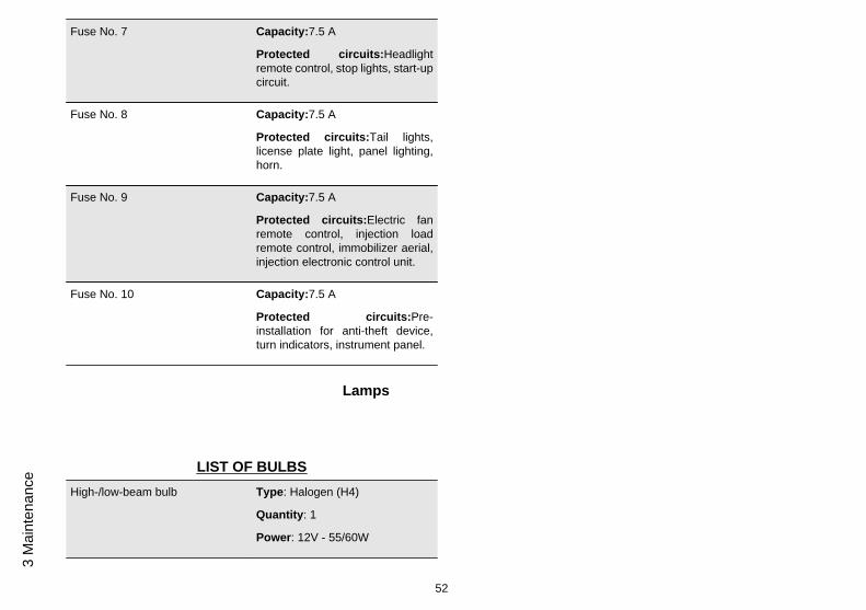
Fuse No. 7 Capacity:7.5 A
Protected circuits:Headlightremote control, stop lights, start-upcircuit.
Fuse No. 8 Capacity:7.5 A
Protected circuits:Tail lights,license plate light, panel lighting,horn.
Fuse No. 9 Capacity:7.5 A
Protected circuits:Electric fanremote control, injection loadremote control, immobilizer aerial,injection electronic control unit.
Fuse No. 10 Capacity:7.5 A
Protected circuits:Pre-installation for anti-theft device,turn indicators, instrument panel.
Lamps
LIST OF BULBS
High-/low-beam bulb Type: Halogen (H4)
Quantity: 1
Power: 12V - 55/60W
52
3 M
aint
enan
ce
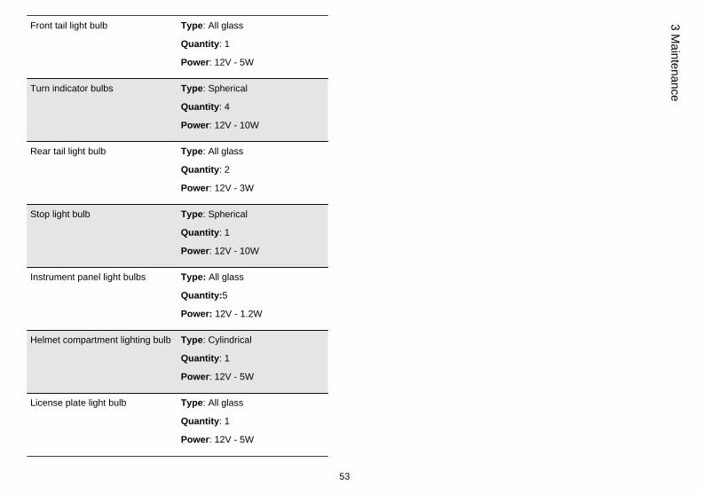
Front tail light bulb Type: All glass
Quantity: 1
Power: 12V - 5W
Turn indicator bulbs Type: Spherical
Quantity: 4
Power: 12V - 10W
Rear tail light bulb Type: All glass
Quantity: 2
Power: 12V - 3W
Stop light bulb Type: Spherical
Quantity: 1
Power: 12V - 10W
Instrument panel light bulbs Type: All glass
Quantity:5
Power: 12V - 1.2W
Helmet compartment lighting bulb Type: Cylindrical
Quantity: 1
Power: 12V - 5W
License plate light bulb Type: All glass
Quantity: 1
Power: 12V - 5W
53
3 Maintenance
03_24
03_25
03_26
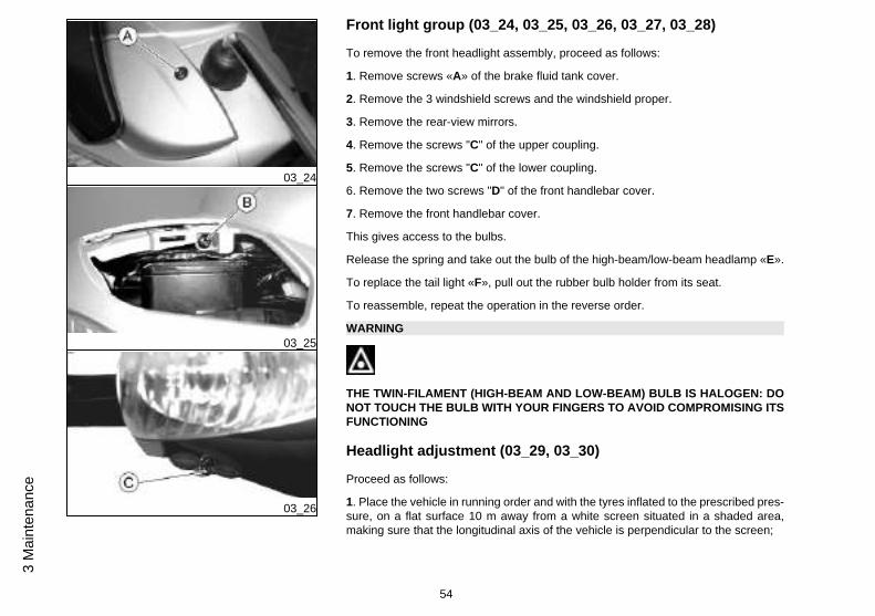
Front light group (03_24, 03_25, 03_26, 03_27, 03_28)
To remove the front headlight assembly, proceed as follows:
1. Remove screws «A» of the brake fluid tank cover.
2. Remove the 3 windshield screws and the windshield proper.
3. Remove the rear-view mirrors.
4. Remove the screws "C" of the upper coupling.
5. Remove the screws "C" of the lower coupling.
6. Remove the two screws "D" of the front handlebar cover.
7. Remove the front handlebar cover.
This gives access to the bulbs.
Release the spring and take out the bulb of the high-beam/low-beam headlamp «E».
To replace the tail light «F», pull out the rubber bulb holder from its seat.
To reassemble, repeat the operation in the reverse order.
WARNING
THE TWIN-FILAMENT (HIGH-BEAM AND LOW-BEAM) BULB IS HALOGEN: DONOT TOUCH THE BULB WITH YOUR FINGERS TO AVOID COMPROMISING ITSFUNCTIONING
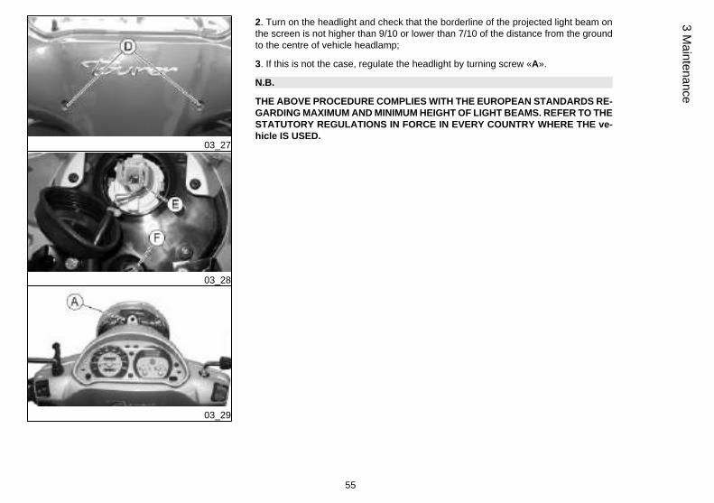
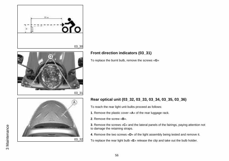
Headlight adjustment (03_29, 03_30)
Proceed as follows:
1. Place the vehicle in running order and with the tyres inflated to the prescribed pres-sure, on a flat surface 10 m away from a white screen situated in a shaded area,making sure that the longitudinal axis of the vehicle is perpendicular to the screen;
54
3 M
aint
enan
ce
03_27
03_28
03_29
2. Turn on the headlight and check that the borderline of the projected light beam onthe screen is not higher than 9/10 or lower than 7/10 of the distance from the groundto the centre of vehicle headlamp;
3. If this is not the case, regulate the headlight by turning screw «A».
N.B.
THE ABOVE PROCEDURE COMPLIES WITH THE EUROPEAN STANDARDS RE-GARDING MAXIMUM AND MINIMUM HEIGHT OF LIGHT BEAMS. REFER TO THESTATUTORY REGULATIONS IN FORCE IN EVERY COUNTRY WHERE THE ve-hicle IS USED.
55
3 Maintenance
03_30
03_31
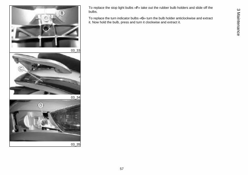
Front direction indicators (03_31)
To replace the burnt bulb, remove the screws «G»
03_32
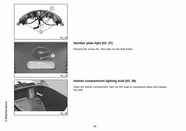
Rear optical unit (03_32, 03_33, 03_34, 03_35, 03_36)
To reach the rear light unit bulbs proceed as follows:
1. Remove the plastic cover «A» of the rear luggage rack.
2. Remove the screw «B».
3. Remove the screws «C» and the lateral panels of the fairings, paying attention notto damage the retaining straps.
4. Remove the two screws «D» of the light assembly being tested and remove it.
To replace the rear light bulb «E» release the clip and take out the bulb holder.
56
3 M
aint
enan
ce
03_33
03_34
03_35
To replace the stop light bulbs «F» take out the rubber bulb holders and slide off thebulbs.
To replace the turn indicator bulbs «G» turn the bulb holder anticlockwise and extractit. Now hold the bulb, press and turn it clockwise and extract it.
57
3 Maintenance
03_36
03_37
Number plate light (03_37)
Remove the screw «C», then take out the bulb holder.
03_38
Helmet compartment lighting bulb (03_38)
Open the helmet compartment, take out the snap-on transparent glass and replacethe bulb.
58
3 M
aint
enan
ce
Rear-view mirrors
Adjust the mirrors by applying slight pressure to the side of the mirror to move it to thedesired position.
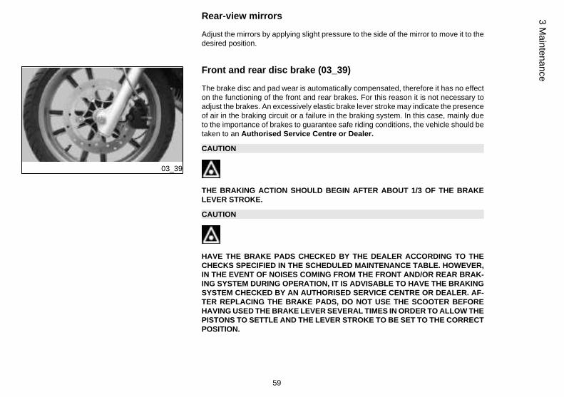
03_39
Front and rear disc brake (03_39)
The brake disc and pad wear is automatically compensated, therefore it has no effecton the functioning of the front and rear brakes. For this reason it is not necessary toadjust the brakes. An excessively elastic brake lever stroke may indicate the presenceof air in the braking circuit or a failure in the braking system. In this case, mainly dueto the importance of brakes to guarantee safe riding conditions, the vehicle should betaken to an Authorised Service Centre or Dealer.
CAUTION
THE BRAKING ACTION SHOULD BEGIN AFTER ABOUT 1/3 OF THE BRAKELEVER STROKE.
CAUTION
HAVE THE BRAKE PADS CHECKED BY THE DEALER ACCORDING TO THECHECKS SPECIFIED IN THE SCHEDULED MAINTENANCE TABLE. HOWEVER,IN THE EVENT OF NOISES COMING FROM THE FRONT AND/OR REAR BRAK-ING SYSTEM DURING OPERATION, IT IS ADVISABLE TO HAVE THE BRAKINGSYSTEM CHECKED BY AN AUTHORISED SERVICE CENTRE OR DEALER. AF-TER REPLACING THE BRAKE PADS, DO NOT USE THE SCOOTER BEFOREHAVING USED THE BRAKE LEVER SEVERAL TIMES IN ORDER TO ALLOW THEPISTONS TO SETTLE AND THE LEVER STROKE TO BE SET TO THE CORRECTPOSITION.
59
3 Maintenance
CAUTION
THE PRESENCE OF SAND, MUD, SNOW MIXED WITH SALT, ETC. ON THEROAD, CAN DRASTICALLY REDUCE THE DURATION OF THE BRAKE PADS. INORDER TO AVOID THIS, WE RECOMMEND WASHING THE VEHICLE FRE-QUENTLY WHEN RIDING IN THESE ROAD CONDITIONS.
Puncture
The vehicle is equipped with tubeless tyres (without inner tube). In the event of apuncture, contrary to the situation with a tyre with inner tube, the tyre deflates moreslowly, resulting in a greater steering safety. In the event of a puncture, it is admissibleto make an emergency repair using an "inflate and repair" spray can. For a final repair,take your vehicle to an Authorised Service Centre or Dealer. The replacement of atyre involves removing the wheel in question. Take your vehicle to an AuthorisedService Centre or Dealer for these operations.
CAUTION
TO USE THE "INFLATE AND REPAIR" SPRAY PROPERLY FOLLOW THE IN-STRUCTIONS ON THE PACKAGING.
WARNING
THE WHEELS FITTED WITH TYRES SHOULD ALWAYS BE BALANCED. RIDINGTHE VEHICLE WITH VERY LOW TYRE PRESSURE OR WITH INCORRECTLYBALANCED TYRES CAN LEAD TO DANGEROUS STEERING VIBRATIONS.
60
3 M
aint
enan
ce
03_40
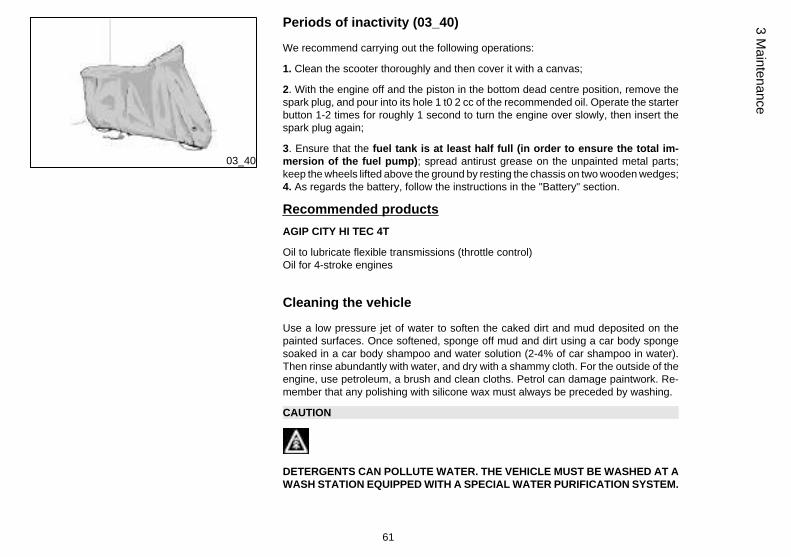
Periods of inactivity (03_40)
We recommend carrying out the following operations:
1. Clean the scooter thoroughly and then cover it with a canvas;
2. With the engine off and the piston in the bottom dead centre position, remove thespark plug, and pour into its hole 1 t0 2 cc of the recommended oil. Operate the starterbutton 1-2 times for roughly 1 second to turn the engine over slowly, then insert thespark plug again;
3. Ensure that the fuel tank is at least half full (in order to ensure the total im-mersion of the fuel pump); spread antirust grease on the unpainted metal parts;keep the wheels lifted above the ground by resting the chassis on two wooden wedges;4. As regards the battery, follow the instructions in the "Battery" section.
Recommended products
AGIP CITY HI TEC 4T
Oil to lubricate flexible transmissions (throttle control)Oil for 4-stroke engines
Cleaning the vehicle
Use a low pressure jet of water to soften the caked dirt and mud deposited on thepainted surfaces. Once softened, sponge off mud and dirt using a car body spongesoaked in a car body shampoo and water solution (2-4% of car shampoo in water).Then rinse abundantly with water, and dry with a shammy cloth. For the outside of theengine, use petroleum, a brush and clean cloths. Petrol can damage paintwork. Re-member that any polishing with silicone wax must always be preceded by washing.
CAUTION
DETERGENTS CAN POLLUTE WATER. THE VEHICLE MUST BE WASHED AT AWASH STATION EQUIPPED WITH A SPECIAL WATER PURIFICATION SYSTEM.
61
3 Maintenance
WARNING
THE USE OF A HIGH-PRESSURE WATER JET IS STRONGLY DISCOURAGEDFOR ANY ENGINE CLEANING OPERATION; HOWEVER, IF NO OTHER MEANSARE AVAILABLE, IT IS THEN NECESSARY TO:
• ONLY USE THE FAN JET.
• DO NOT PLACE THE NOZZLE CLOSER THAN 60 CM.
• DO NOT USE WATER AT TEMPERATURES OVER 40ºC.
• DO NOT USE HIGH-PRESSURE WATER JETS.
• DO NOT STEAM WASH.
• DO NOT DIRECT THE JET AT: THE CARBURETTOR, THE ELECTRIC CABLES,THE SLOT DIFFUSERS IN THE TRANSMISSION COVER AND THE SCROLLCOVER.
CAUTION
NEVER WASH THE SCOOTER IN DIRECT SUNLIGHT, ESPECIALLY IN SUMMERWHEN THE BODYWORK IS STILL HOT AS THE SHAMPOO COULD DAMAGETHE PAINTWORK IF IT DRIES BEFORE BEING RINSED OFF. NEVER USECLOTHS SOAKED IN ALCOHOL, PETROL, DIESEL OIL OR KEROSENE FORCLEANING THE PAINTED OR PLASTIC SURFACES, IN ORDER NOT TO DAM-AGE THE LUSTRE FINISH OR ALTER THE MECHANICAL PROPERTIES. USINGSILICONE-BASED WAX CAN DAMAGE THE PAINTED SURFACES, DEPENDINGON THE VEHICLE COLOUR (SATIN COLOURS). FOR FURTHER INFORMATIONON THIS MATTER, CONTACT AN AUTHORISED SERVICE CENTRE .
Troubleshooting
62
3 M
aint
enan
ce
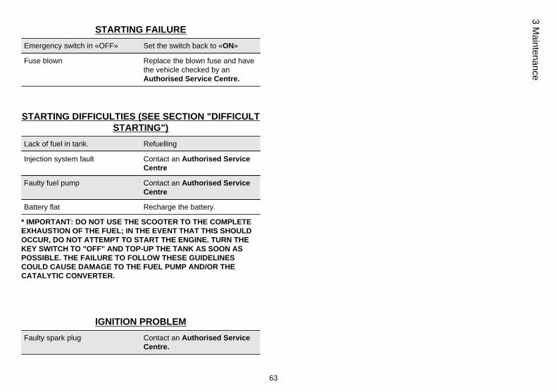
STARTING FAILURE
Emergency switch in «OFF» Set the switch back to «ON»
Fuse blown Replace the blown fuse and havethe vehicle checked by anAuthorised Service Centre.
STARTING DIFFICULTIES (SEE SECTION "DIFFICULTSTARTING")
Lack of fuel in tank. Refuelling
Injection system fault Contact an Authorised ServiceCentre
Faulty fuel pump Contact an Authorised ServiceCentre
Battery flat Recharge the battery.
* IMPORTANT: DO NOT USE THE SCOOTER TO THE COMPLETEEXHAUSTION OF THE FUEL; IN THE EVENT THAT THIS SHOULDOCCUR, DO NOT ATTEMPT TO START THE ENGINE. TURN THEKEY SWITCH TO "OFF" AND TOP-UP THE TANK AS SOON ASPOSSIBLE. THE FAILURE TO FOLLOW THESE GUIDELINESCOULD CAUSE DAMAGE TO THE FUEL PUMP AND/OR THECATALYTIC CONVERTER.
IGNITION PROBLEM
Faulty spark plug Contact an Authorised ServiceCentre.
63
3 Maintenance
Faulty ignition / injection controlunit. Due to the presence of highvoltage, this check should only becarried out by an expert.
Contact an Authorised ServiceCentre
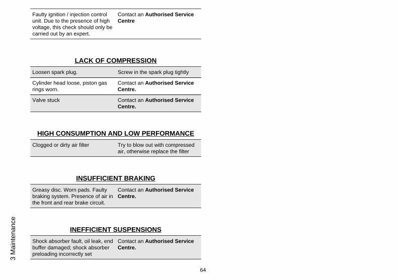
LACK OF COMPRESSION
Loosen spark plug. Screw in the spark plug tightly
Cylinder head loose, piston gasrings worn.
Contact an Authorised ServiceCentre.
Valve stuck Contact an Authorised ServiceCentre.
HIGH CONSUMPTION AND LOW PERFORMANCE
Clogged or dirty air filter Try to blow out with compressedair, otherwise replace the filter
INSUFFICIENT BRAKING
Greasy disc. Worn pads. Faultybraking system. Presence of air inthe front and rear brake circuit.
Contact an Authorised ServiceCentre.
INEFFICIENT SUSPENSIONS
Shock absorber fault, oil leak, endbuffer damaged; shock absorberpreloading incorrectly set
Contact an Authorised ServiceCentre.
64
3 M
aint
enan
ce
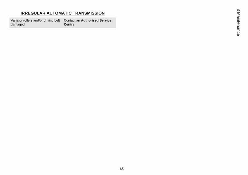
IRREGULAR AUTOMATIC TRANSMISSION
Variator rollers and/or driving beltdamaged
Contact an Authorised ServiceCentre.
65
3 Maintenance

66
3 M
aint
enan
ce

BeverlyTourer 250ie
Chap. 04Technical data
67
04_01
68
4 T
echn
ical
dat
a
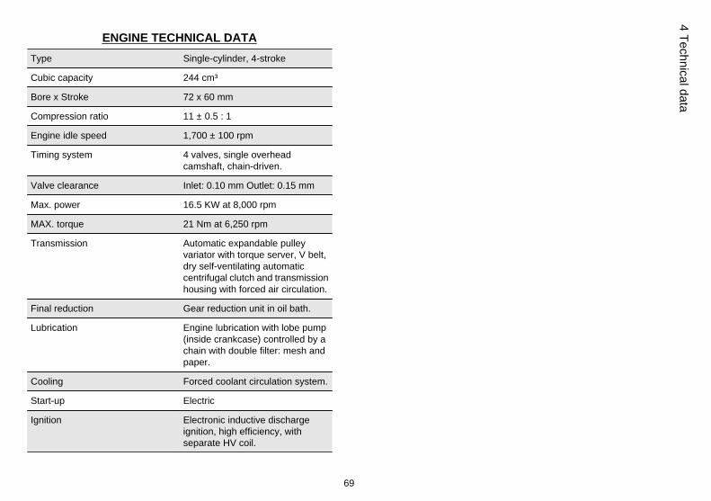
ENGINE TECHNICAL DATA
Type Single-cylinder, 4-stroke
Cubic capacity 244 cm³
Bore x Stroke 72 x 60 mm
Compression ratio 11 ± 0.5 : 1
Engine idle speed 1,700 ± 100 rpm
Timing system 4 valves, single overheadcamshaft, chain-driven.
Valve clearance Inlet: 0.10 mm Outlet: 0.15 mm
Max. power 16.5 KW at 8,000 rpm
MAX. torque 21 Nm at 6,250 rpm
Transmission Automatic expandable pulleyvariator with torque server, V belt,dry self-ventilating automaticcentrifugal clutch and transmissionhousing with forced air circulation.
Final reduction Gear reduction unit in oil bath.
Lubrication Engine lubrication with lobe pump(inside crankcase) controlled by achain with double filter: mesh andpaper.
Cooling Forced coolant circulation system.
Start-up Electric
Ignition Electronic inductive dischargeignition, high efficiency, withseparate HV coil.
69
4 Technical data
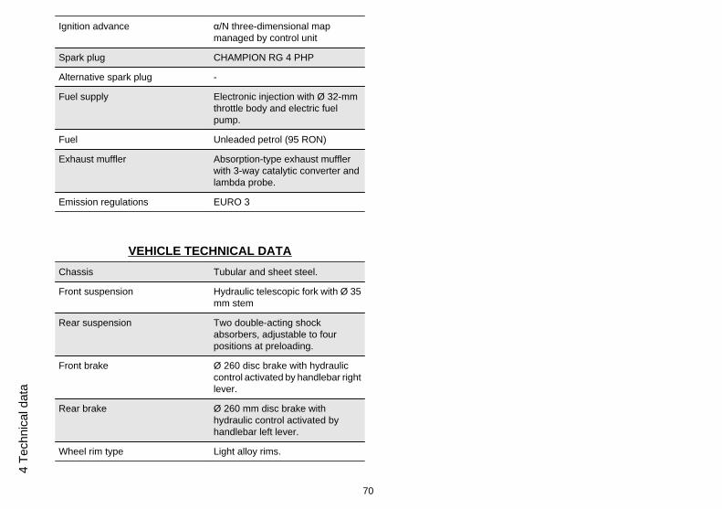
Ignition advance α/N three-dimensional mapmanaged by control unit
Spark plug CHAMPION RG 4 PHP
Alternative spark plug -
Fuel supply Electronic injection with Ø 32-mmthrottle body and electric fuelpump.
Fuel Unleaded petrol (95 RON)
Exhaust muffler Absorption-type exhaust mufflerwith 3-way catalytic converter andlambda probe.
Emission regulations EURO 3
VEHICLE TECHNICAL DATA
Chassis Tubular and sheet steel.
Front suspension Hydraulic telescopic fork with Ø 35mm stem
Rear suspension Two double-acting shockabsorbers, adjustable to fourpositions at preloading.
Front brake Ø 260 disc brake with hydrauliccontrol activated by handlebar rightlever.
Rear brake Ø 260 mm disc brake withhydraulic control activated byhandlebar left lever.
Wheel rim type Light alloy rims.
70
4 T
echn
ical
dat
a
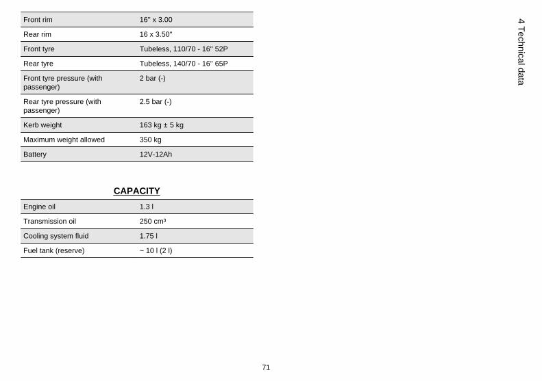
Front rim 16'' x 3.00
Rear rim 16 x 3.50''
Front tyre Tubeless, 110/70 - 16'' 52P
Rear tyre Tubeless, 140/70 - 16'' 65P
Front tyre pressure (withpassenger)
2 bar (-)
Rear tyre pressure (withpassenger)
2.5 bar (-)
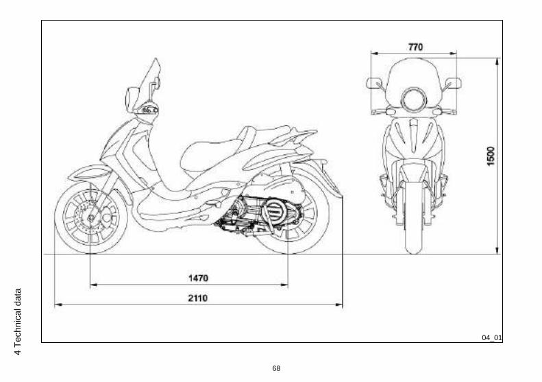
Kerb weight 163 kg ± 5 kg
Maximum weight allowed 350 kg
Battery 12V-12Ah
CAPACITY
Engine oil 1.3 l
Transmission oil 250 cm³
Cooling system fluid 1.75 l
Fuel tank (reserve) ~ 10 l (2 l)
71
4 Technical data
04_02
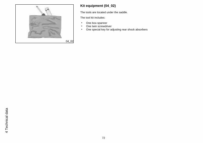
Kit equipment (04_02)
The tools are located under the saddle.
The tool kit includes:
• One box-spanner• One twin screwdriver• One special key for adjusting rear shock absorbers
72
4 T
echn
ical
dat
a
BeverlyTourer 250ie
Chap. 05Spare parts and
accessories
73
05_01
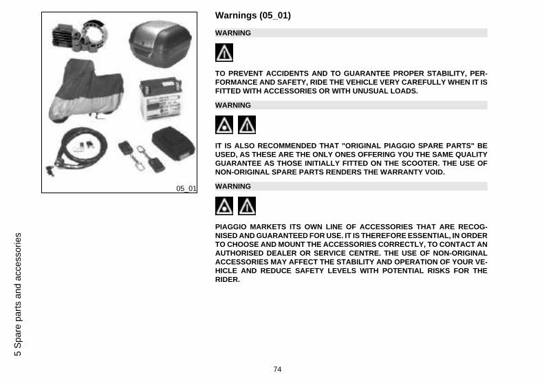
Warnings (05_01)
WARNING
TO PREVENT ACCIDENTS AND TO GUARANTEE PROPER STABILITY, PER-FORMANCE AND SAFETY, RIDE THE VEHICLE VERY CAREFULLY WHEN IT ISFITTED WITH ACCESSORIES OR WITH UNUSUAL LOADS.
WARNING
IT IS ALSO RECOMMENDED THAT "ORIGINAL PIAGGIO SPARE PARTS" BEUSED, AS THESE ARE THE ONLY ONES OFFERING YOU THE SAME QUALITYGUARANTEE AS THOSE INITIALLY FITTED ON THE SCOOTER. THE USE OFNON-ORIGINAL SPARE PARTS RENDERS THE WARRANTY VOID.
WARNING
PIAGGIO MARKETS ITS OWN LINE OF ACCESSORIES THAT ARE RECOG-NISED AND GUARANTEED FOR USE. IT IS THEREFORE ESSENTIAL, IN ORDERTO CHOOSE AND MOUNT THE ACCESSORIES CORRECTLY, TO CONTACT ANAUTHORISED DEALER OR SERVICE CENTRE. THE USE OF NON-ORIGINALACCESSORIES MAY AFFECT THE STABILITY AND OPERATION OF YOUR VE-HICLE AND REDUCE SAFETY LEVELS WITH POTENTIAL RISKS FOR THERIDER.
74
5 S
pare
par
ts a
nd a
cces
sorie
s
WARNING
NEVER RIDE THE SCOOTER EQUIPPED WITH ACCESSORIES (TOP BOX AND/OR WINDSHIELD) AT A SPEED HIGHER THAN 100 km/h.
THE SCOOTER CAN BE RIDDEN AT A HIGHER SPEED WITHOUT THE ACCES-SORIES MENTIONED BEFORE WITHIN THE LIMITS ESTABLISHED BY LAW.
IF THERE SHOULD BE NOT-PIAGGIO ACCESSORIES INSTALLED, OR AN AB-NORMAL LOAD, OR IF THE SCOOTER IS NOT IN A GENERALLY GOOD CON-DITION, OR WHENEVER WEATHER CONDITIONS DEMAND IT, SPEED SHOULDBE REDUCED FURTHER.
WARNING
BE EXTREMELY CAREFUL WHEN INSTALLING AND REMOVING THE MECHAN-ICAL ANTITHEFT DEVICE ON THE VEHICLE (U-SHAPED PADLOCK, DISCBLOCK, ETC.).
MAINLY DUE TO THE PROXIMITY TO THE BRAKE PIPES, TRANSMISSIONSAND/OR ELECTRIC CABLES, AN INCORRECT INSTALLATION OR REMOVALOF THE ANTITHEFT DEVICE AS WELL AS LEAVING IT ON BEFORE STARTINGTHE VEHICLE CAN SERIOUSLY DAMAGE ITS COMPONENTS AND AFFECT THECORRECT FUNCTIONING OF THE VEHICLE AND HARM THE USER.
75
5 Spare parts and accessories

76
5 S
pare
par
ts a
nd a
cces
sorie
s
BeverlyTourer 250ie
Chap. 06Programmedmaintenance
77
06_01
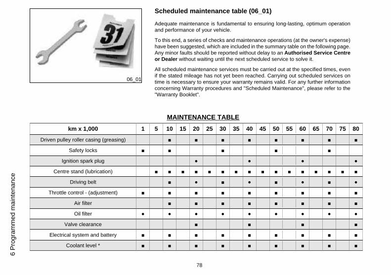
Scheduled maintenance table (06_01)
Adequate maintenance is fundamental to ensuring long-lasting, optimum operationand performance of your vehicle.
To this end, a series of checks and maintenance operations (at the owner's expense)have been suggested, which are included in the summary table on the following page.Any minor faults should be reported without delay to an Authorised Service Centreor Dealer without waiting until the next scheduled service to solve it.
All scheduled maintenance services must be carried out at the specified times, evenif the stated mileage has not yet been reached. Carrying out scheduled services ontime is necessary to ensure your warranty remains valid. For any further informationconcerning Warranty procedures and "Scheduled Maintenance", please refer to the"Warranty Booklet".
MAINTENANCE TABLE
km x 1,000 1 5 10 15 20 25 30 35 40 45 50 55 60 65 70 75 80
Driven pulley roller casing (greasing) ■ ■ ■ ■ ■ ■ ■ ■
Safety locks ■ ■ ■ ■ ■
Ignition spark plug ● ● ● ●
Centre stand (lubrication) ■ ■ ■ ■ ■ ■ ■ ■ ■ ■ ■ ■ ■ ■ ■ ■
Driving belt ■ ● ■ ● ■ ● ■ ●
Throttle control - (adjustment) ■ ■ ■ ■ ■ ■ ■ ■ ■
Air filter ■ ■ ■ ■ ■ ■ ■ ■
Oil filter ● ● ● ● ● ● ● ● ●
Valve clearance ■ ■ ■ ■
Electrical system and battery ■ ■ ■ ■ ■ ■ ■ ■ ■
Coolant level * ■ ■ ■ ■ ■ ■ ■ ■ ■
78
6 P
rogr
amm
ed m
aint
enan
ce
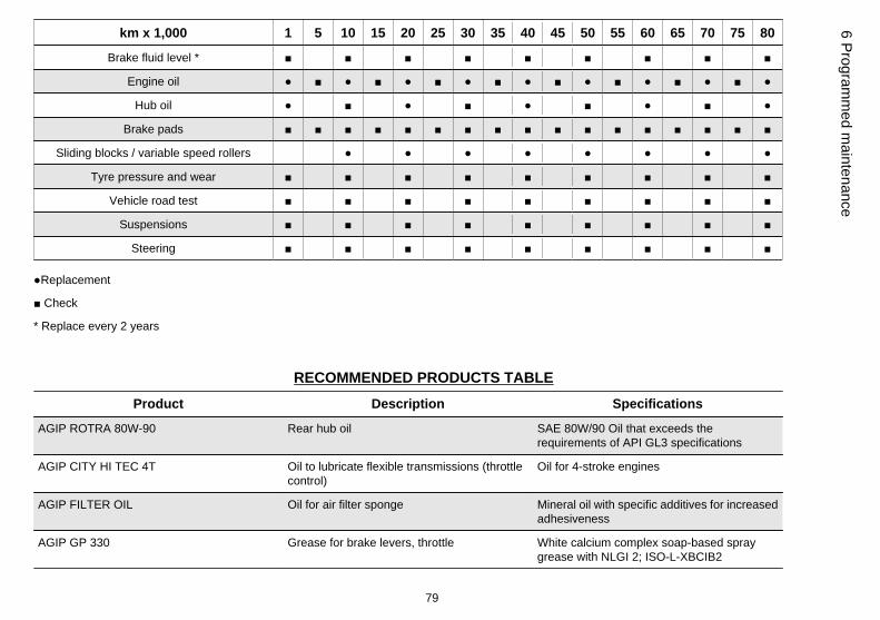
km x 1,000 1 5 10 15 20 25 30 35 40 45 50 55 60 65 70 75 80
Brake fluid level * ■ ■ ■ ■ ■ ■ ■ ■ ■
Engine oil ● ■ ● ■ ● ■ ● ■ ● ■ ● ■ ● ■ ● ■ ●
Hub oil ● ■ ● ■ ● ■ ● ■ ●
Brake pads ■ ■ ■ ■ ■ ■ ■ ■ ■ ■ ■ ■ ■ ■ ■ ■ ■
Sliding blocks / variable speed rollers ● ● ● ● ● ● ● ●
Tyre pressure and wear ■ ■ ■ ■ ■ ■ ■ ■ ■
Vehicle road test ■ ■ ■ ■ ■ ■ ■ ■ ■
Suspensions ■ ■ ■ ■ ■ ■ ■ ■ ■
Steering ■ ■ ■ ■ ■ ■ ■ ■ ■
●Replacement
■ Check
* Replace every 2 years
RECOMMENDED PRODUCTS TABLE
Product Description Specifications
AGIP ROTRA 80W-90 Rear hub oil SAE 80W/90 Oil that exceeds therequirements of API GL3 specifications
AGIP CITY HI TEC 4T Oil to lubricate flexible transmissions (throttlecontrol)
Oil for 4-stroke engines
AGIP FILTER OIL Oil for air filter sponge Mineral oil with specific additives for increasedadhesiveness
AGIP GP 330 Grease for brake levers, throttle White calcium complex soap-based spraygrease with NLGI 2; ISO-L-XBCIB2
79
6 Program
med m
aintenance
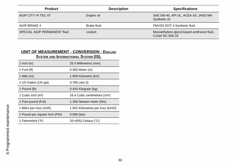
Product Description Specifications
AGIP CITY HI TEC 4T Engine oil SAE 5W-40, API SL, ACEA A3, JASO MASynthetic oil
AGIP BRAKE 4 Brake fluid FMVSS DOT 4 Synthetic fluid
SPECIAL AGIP PERMANENT fluid coolant Monoethylene glycol-based antifreeze fluid,CUNA NC 956-16
UNIT OF MEASUREMENT - CONVERSION - ENGLISH
SYSTEM AND INTERNATIONAL SYSTEM (IS).
1 Inch (in) 25.4 Millimetres (mm)
1 Foot (ft) 0.305 Meter (m)
1 Mile (mi) 1.609 Kilometre (km)
1 US Gallon (US gal) 3.785 Litre (l)
1 Pound (lb) 0.454 Kilogram (kg)
1 Cubic inch (in³) 16.4 Cubic centimetres (cm³)
1 Foot pound (ft lb) 1.356 Newton meter (Nm)
1 Miles per hour (mi/h) 1.602 Kilometres per hour (km/h)
1 Pound per square inch (PSI) 0.069 (bar)
1 Fahrenheit (°F) 32+(9/5) Celsius (°C)
80
6 P
rogr
amm
ed m
aint
enan
ce
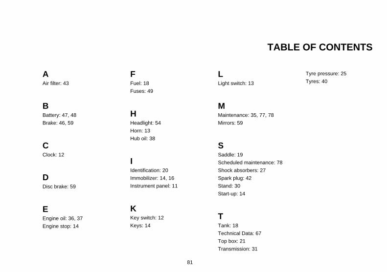
TABLE OF CONTENTS
AAir filter: 43
BBattery: 47, 48
Brake: 46, 59
CClock: 12
DDisc brake: 59
EEngine oil: 36, 37
Engine stop: 14
FFuel: 18
Fuses: 49
HHeadlight: 54
Horn: 13
Hub oil: 38
IIdentification: 20
Immobilizer: 14, 16
Instrument panel: 11
KKey switch: 12
Keys: 14
LLight switch: 13
MMaintenance: 35, 77, 78
Mirrors: 59
SSaddle: 19
Scheduled maintenance: 78
Shock absorbers: 27
Spark plug: 42
Stand: 30
Start-up: 14
TTank: 18
Technical Data: 67
Top box: 21
Transmission: 31
Tyre pressure: 25
Tyres: 40
81

The descriptions and illustrations given in this publication are not binding. While the basic features as described and illustrated in this manual remainunchanged, PIAGGIO - GILERA reserves the right, at any time and without being required to update this publication beforehand, to make any changesto components, parts or accessory supplies, which it considers necessary to improve the product or which are required for manufacturing or constructionreasons.
Not all versions shown in this publication are available in all Countries. The availability of individual versions should be confirmed with the official Piaggio sales network.
"© Copyright 2007 - PIAGGIO & C. S.p.A. Pontedera. All rights reserved. Reproduction of this publication in whole or in part is prohibited."
PIAGGIO & C. S.p.A. - After-Sales
V.le Rinaldo Piaggio, 23 - 56025 PONTEDERA (Pi)