3 before driving - team-bhp
TRANSCRIPT
13
797-74E-I
3
BEFORE DRIVING
BEFORE DRIVING
Fuel Recommendation ....................................................................................... 3-1
Keys ......................................................................................................................3-2
Door Locks ..........................................................................................................3-3
Windows ............................................................................................................... 3-4
Mirrors ...................................................................................................................3-5
Driver's Seat Adjustment ..................................................................................3-5
Adjustable Head Restraints (if equipped) ..................................................... 3-6
Seat Belts ............................................................................................................3-7
14
797-74E-I
3-1
BEFORE DRIVING
FUEL RECOMMENDATION
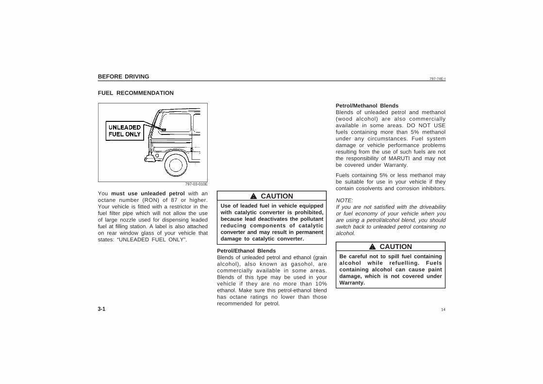
You must use unleaded petrol with anoctane number (RON) of 87 or higher.Your vehicle is fitted with a restrictor in thefuel filter pipe which will not allow the useof large nozzle used for dispensing leadedfuel at filling station. A label is also attachedon rear window glass of your vehicle thatstates: “UNLEADED FUEL ONLY”.
Petrol/Methanol BlendsBlends of unleaded petrol and methanol(wood alcohol) are also commerciallyavailable in some areas. DO NOT USEfuels containing more than 5% methanolunder any circumstances. Fuel systemdamage or vehicle performance problemsresulting from the use of such fuels are notthe responsibility of MARUTI and may notbe covered under Warranty.
Fuels containing 5% or less methanol maybe suitable for use in your vehicle if theycontain cosolvents and corrosion inhibitors.
NOTE:If you are not satisfied with the driveabilityor fuel economy of your vehicle when youare using a petrol/alcohol blend, you shouldswitch back to unleaded petrol containing noalcohol.
Be careful not to spill fuel containingalcohol while refuelling. Fuelscontaining alcohol can cause paintdamage, which is not covered underWarranty.
Use of leaded fuel in vehicle equippedwith catalytic converter is prohibited,because lead deactivates the pollutantreducing components of catalyticconverter and may result in permanentdamage to catalytic converter.
Petrol/Ethanol BlendsBlends of unleaded petrol and ethanol (grainalcohol), also known as gasohol, arecommercially available in some areas.Blends of this type may be used in yourvehicle if they are no more than 10%ethanol. Make sure this petrol-ethanol blendhas octane ratings no lower than thoserecommended for petrol.
wwwww CAUTION
wwwww CAUTION
797-03-010E
15
797-74E-I BEFORE DRIVING
3-2
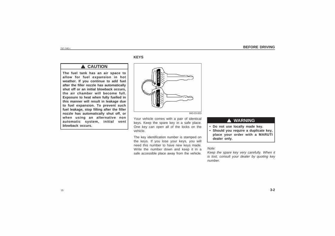
Your vehicle comes with a pair of identicalkeys. Keep the spare key in a safe place.One key can open all of the locks on thevehicle.
The key identification number is stamped onthe keys. If you lose your keys, you willneed this number to have new keys made.Write the number down and keep it in asafe accessible place away from the vehicle.
KEYS
The fuel tank has an air space toallow for fuel expansion in hotweather. If you continue to add fuelafter the filler nozzle has automaticallyshut off or an initial blowback occurs,the air chamber will become full.Exposure to heat when fully fuelled inthis manner will result in leakage dueto fuel expansion. To prevent suchfuel leakage, stop filling after the fillernozzle has automatically shut off, orwhen using an alternative nonautomatic system, initial ventblowback occurs.
wwwww CAUTION
wwwww WARNING• Do not use locally made key.• Should you require a duplicate key,
place your order with a MARUTIdealer only.
Note:Keep the spare key very carefully. When itis lost, consult your dealer by quoting keynumber.
843-03-003
16
797-74E-IBEFORE DRIVING
3-3
DOOR LOCKS
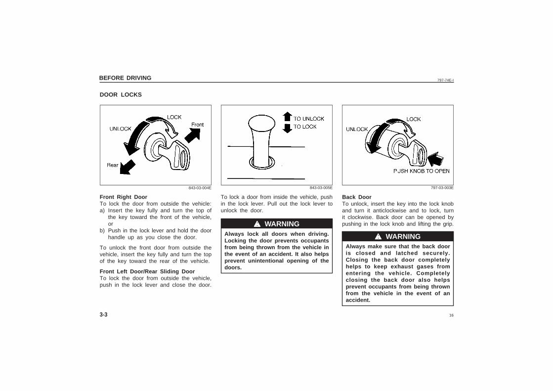
To lock a door from inside the vehicle, pushin the lock lever. Pull out the lock lever tounlock the door.
Always lock all doors when driving.Locking the door prevents occupantsfrom being thrown from the vehicle inthe event of an accident. It also helpsprevent unintentional opening of thedoors.
wwwww WARNING
843-03-004E 843-03-005E
Front Right DoorTo lock the door from outside the vehicle:a) Insert the key fully and turn the top of
the key toward the front of the vehicle,or
b) Push in the lock lever and hold the doorhandle up as you close the door.
To unlock the front door from outside thevehicle, insert the key fully and turn the topof the key toward the rear of the vehicle.
Front Left Door/Rear Sliding DoorTo lock the door from outside the vehicle,push in the lock lever and close the door.
Back DoorTo unlock, insert the key into the lock knoband turn it anticlockwise and to lock, turnit clockwise. Back door can be opened bypushing in the lock knob and lifting the grip.
Always make sure that the back dooris closed and latched securely.Closing the back door completelyhelps to keep exhaust gases fromentering the vehicle. Completelyclosing the back door also helpsprevent occupants from being thrownfrom the vehicle in the event of anaccident.
797-03-003E
wwwww WARNING
17
797-74E-I BEFORE DRIVING
3-4
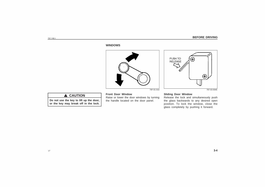
WINDOWS
Front Door WindowRaise or lower the door windows by turningthe handle located on the door panel.
70F-01-010
Do not use the key to lift up the door,or the key may break off in the lock.
wwwww CAUTION Sliding Door WindowRelease the lock and simultaneously pushthe glass backwards to any desired openposition. To lock the window, close theglass completely by pushing it forward.
797-03-004E
18
797-74E-IBEFORE DRIVING
3-5
DRIVER'S SEAT ADJUSTMENT
wwwww WARNING
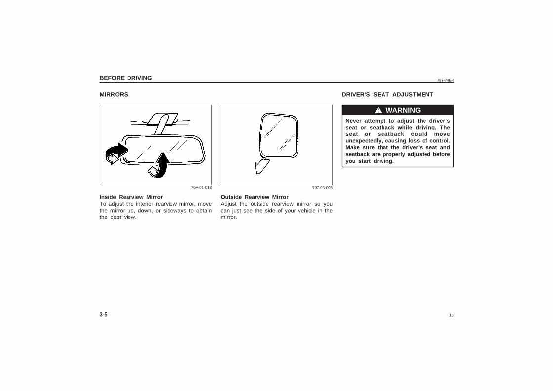
MIRRORS
Inside Rearview MirrorTo adjust the interior rearview mirror, movethe mirror up, down, or sideways to obtainthe best view.
Outside Rearview MirrorAdjust the outside rearview mirror so youcan just see the side of your vehicle in themirror.
70F-01-013 797-03-006
Never attempt to adjust the driver’sseat or seatback while driving. Theseat or seatback could moveunexpectedly, causing loss of control.Make sure that the driver’s seat andseatback are properly adjusted beforeyou start driving.
19
797-74E-I BEFORE DRIVING
3-6
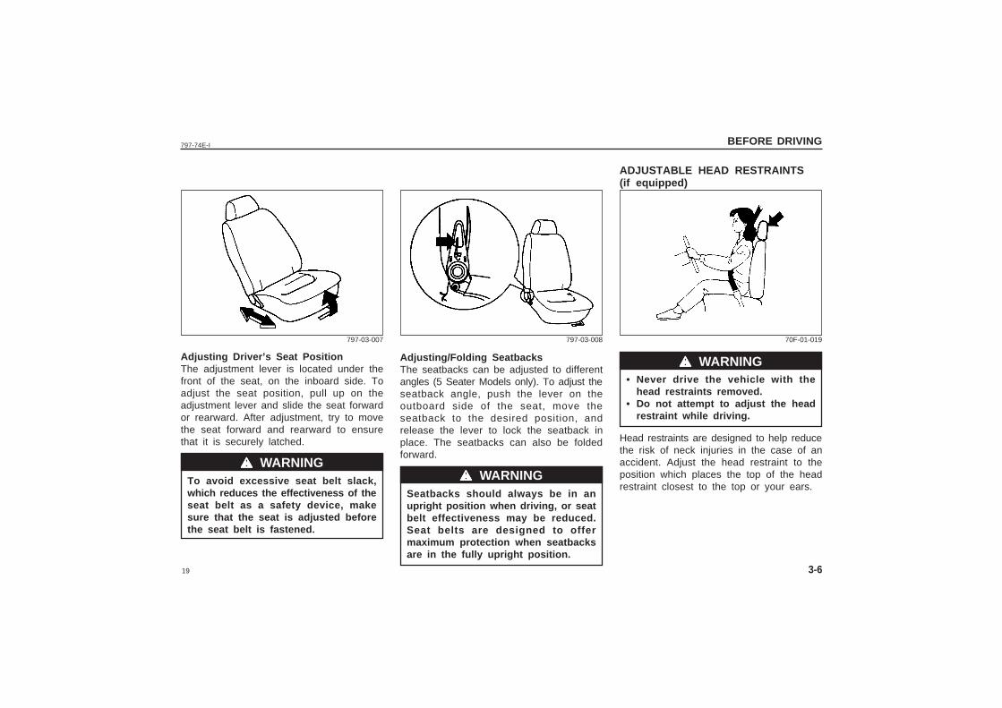
Adjusting Driver’s Seat PositionThe adjustment lever is located under thefront of the seat, on the inboard side. Toadjust the seat position, pull up on theadjustment lever and slide the seat forwardor rearward. After adjustment, try to movethe seat forward and rearward to ensurethat it is securely latched.
To avoid excessive seat belt slack,which reduces the effectiveness of theseat belt as a safety device, makesure that the seat is adjusted beforethe seat belt is fastened.
Adjusting/Folding SeatbacksThe seatbacks can be adjusted to differentangles (5 Seater Models only). To adjust theseatback angle, push the lever on theoutboard side of the seat, move theseatback to the desired position, andrelease the lever to lock the seatback inplace. The seatbacks can also be foldedforward.
Seatbacks should always be in anupright position when driving, or seatbelt effectiveness may be reduced.Seat belts are designed to offermaximum protection when seatbacksare in the fully upright position.
ADJUSTABLE HEAD RESTRAINTS(if equipped)
wwwww WARNING• Never drive the vehicle with the
head restraints removed.• Do not attempt to adjust the head
restraint while driving.
Head restraints are designed to help reducethe risk of neck injuries in the case of anaccident. Adjust the head restraint to theposition which places the top of the headrestraint closest to the top or your ears.
797-03-007 797-03-008 70F-01-019
wwwww WARNINGwwwww WARNING
20
797-74E-IBEFORE DRIVING
3-7
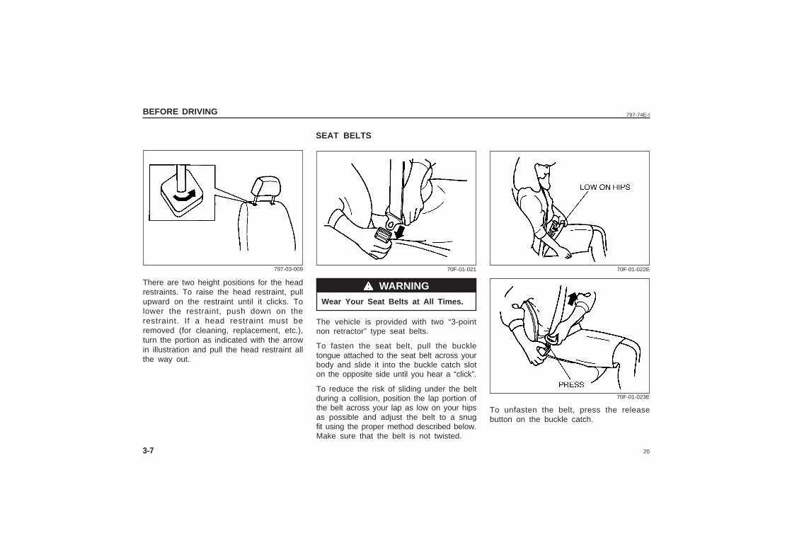
There are two height positions for the headrestraints. To raise the head restraint, pullupward on the restraint until it clicks. Tolower the restraint, push down on therestraint. If a head restraint must beremoved (for cleaning, replacement, etc.),turn the portion as indicated with the arrowin illustration and pull the head restraint allthe way out.
Wear Your Seat Belts at All Times.
The vehicle is provided with two “3-pointnon retractor” type seat belts.
To fasten the seat belt, pull the buckletongue attached to the seat belt across yourbody and slide it into the buckle catch sloton the opposite side until you hear a “click”.
To reduce the risk of sliding under the beltduring a collision, position the lap portion ofthe belt across your lap as low on your hipsas possible and adjust the belt to a snugfit using the proper method described below.Make sure that the belt is not twisted.
SEAT BELTS
wwwww WARNING
797-03-009 70F-01-021 70F-01-022E
70F-01-023E
To unfasten the belt, press the releasebutton on the buckle catch.
21
797-74E-I BEFORE DRIVING
3-8
843E-01-003E
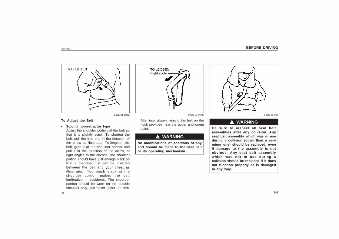
To Adjust the Belt
• 3-point non-retractor typeAdjust the shoulder portion of the belt sothat it is slightly slack. To shorten thebelt, pull the free end in the direction ofthe arrow as illustrated. To lengthen thebelt, grab it at the shoulder anchor andpull it in the direction of the arrow, atright angles to the anchor. The shoulderportion should have just enough slack sothat a clenched fist can be insertedbetween the belt and your chest asillustrated. Too much slack at theshoulder portion makes the beltineffective in accidents. The shoulderportion should be worn on the outsideshoulder only, and never under the arm.
After use, always rehang the belt on thehook provided near the upper anchoragepoint.
No modifications or additions of anysort should be made to the seat beltor its operating mechanism.
843E-01-004E
wwwww WARNING
843E-01-005
Be sure to inspect all seat beltassemblies after any collision. Anyseat belt assembly which was in useduring a collision (other than a veryminor one) should be replaced, evenif damage to the assembly is notobvious. Any seat belt assemblywhich was not in use during acollision should be replaced if it doesnot function properly or is damagedin any way.
wwwww WARNING
22
797-74E-IBEFORE DRIVING
3-9
• Never allow persons to ride in thecargo area of a vehicle. In the eventof an accident, there is a muchgreater risk of injury for personswho are not riding in a seat withtheir seat belt securely fastened.
• Seat belts should always beadjusted so the lap portion of thebelt is worn low across the pelvis,not across the waist. Shoulderstraps should be worn on theoutside shoulder only, and neverunder the arm. Seat belts shouldnever be worn with the strapstwisted and should be adjusted astightly as is comfortable to providethe protection for which they havebeen designed. A slack belt willprovide less protection than onewhich is snug.
• Make sure that each seat belt buckleis inserted into the proper bucklecatch.
• Do not wear your seat belt overhard or breakable objects in your
pockets or on your clothing. If anaccident occurs, objects such asglasses, pens, etc. under the seatbelt can cause injury.
• Never use the same seat belt onmore than one occupant and neverattach a seat belt over an infant orchild being held on an occupant’slap. Such seat belt use could causeserious injury in the event of anaccident.
• Pregnant women should use seatbelts, although specific recommen-dations about restraint use shouldbe made by the woman’s medicaladvisor.
• Periodically inspect seat beltassemblies for excessive wear anddamage. Seat belts should bereplaced if webbing becomes frayed,contaminated, or damaged in anyway. It is essential to replace theentire seat belt assembly after it hasbeen stressed in an impact, even ifdamage to the assembly is notobvious.
• Infants and small children shouldnever be transported unless theyare properly restrained. Restraintsystems for infants and smallchildren can be purchased locallyand should be used. Make sure thatthe system you purchase meetsapplicable safety standards. Readand follow all the directionsprovided by the manufacturer.
• Avoid contamination of seat beltwebbing by polishes, oils,chemicals, and particularly batteryacid. Cleaning may safely be carriedout using mild soap and water.
• For children, if the shoulder beltirritates the neck or face, move thechild closer to the center of thevehicle.
wwwww WARNING wwwww WARNING wwwww WARNING
ˇ̌̌̌̌ ˇ̌̌̌̌
ˇ̌̌̌̌ ˇ̌̌̌̌
23
797-74E-I
4
STEERING COLUMN CONTROLS
STEERING COLUMN CONTROLS
Ignition Switch ....................................................................................................4-1
Lighting/Turn Signal Control Lever ................................................................ 4-2
Hazard Warning Switch..................................................................................... 4-3
Windscreen Wiper and Washer Lever ........................................................... 4-4
Horn .......................................................................................................................4-5
24
797-74E-ISTEERING COLUMN CONTROLS
4-1
IGNITION SWITCH
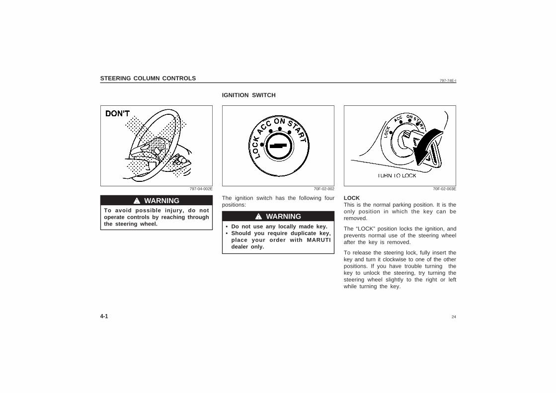
The ignition switch has the following fourpositions:
• Do not use any locally made key.• Should you require duplicate key,
place your order with MARUTIdealer only.
LOCKThis is the normal parking position. It is theonly position in which the key can beremoved.
The “LOCK” position locks the ignition, andprevents normal use of the steering wheelafter the key is removed.
To release the steering lock, fully insert thekey and turn it clockwise to one of the otherpositions. If you have trouble turning thekey to unlock the steering, try turning thesteering wheel slightly to the right or leftwhile turning the key.
To avoid possible injury, do notoperate controls by reaching throughthe steering wheel.
wwwww WARNING
wwwww WARNING
797-04-002E 70F-02-002 70F-02-003E
25
797-74E-I STEERING COLUMN CONTROLS
4-2
• Do not use the starter motor formore than 15 seconds at a time. Ifthe engine does not start; wait 15seconds before trying again. If theengine does not start after severalattempts, check the fuel and ignitionsystems or consult your MARUTIdealer.
• Do not leave the ignition switch inthe “ON” position if the engine isnot running as the battery willdischarge.
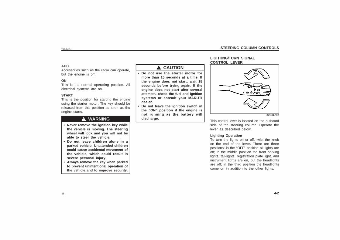
LIGHTING/TURN SIGNALCONTROL LEVER
ACCAccessories such as the radio can operate,but the engine is off.
ONThis is the normal operating position. Allelectrical systems are on.
STARTThis is the position for starting the engineusing the starter motor. The key should bereleased from this position as soon as theengine starts.
• Never remove the ignition key whilethe vehicle is moving. The steeringwheel will lock and you will not beable to steer the vehicle.
• Do not leave children alone in aparked vehicle. Unattended childrencould cause accidental movement ofthe vehicle, which could result insevere personal injury.
• Always remove the key when parkedto prevent unintentional operation ofthe vehicle and to improve security.
This control lever is located on the outboardside of the steering column. Operate thelever as described below.
Lighting OperationTo turn the lights on or off, twist the knobon the end of the lever. There are threepositions: in the “OFF” position all lights areoff; in the middle position the front parkinglights, tail-lights, registration plate light, andinstrument lights are on, but the headlightsare off; in the third position the headlightscome on in addition to the other lights.
wwwww WARNING
wwwww CAUTION
843-04-003
26
797-74E-ISTEERING COLUMN CONTROLS
4-3
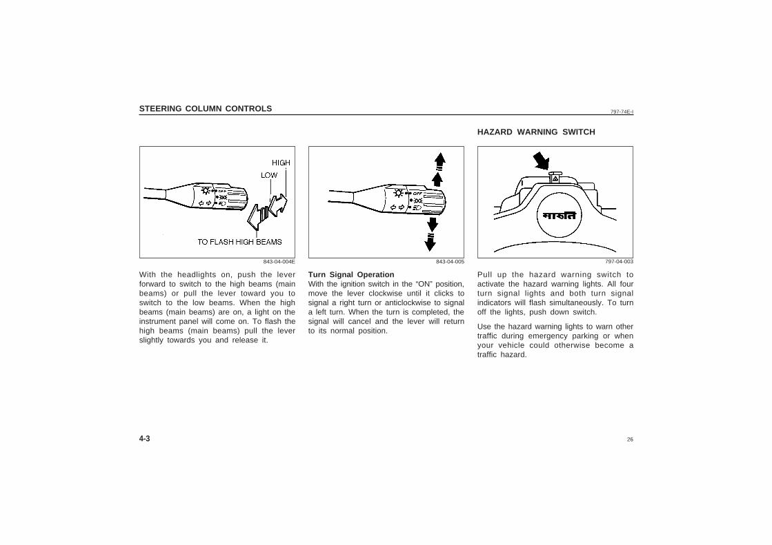
With the headlights on, push the leverforward to switch to the high beams (mainbeams) or pull the lever toward you toswitch to the low beams. When the highbeams (main beams) are on, a light on theinstrument panel will come on. To flash thehigh beams (main beams) pull the leverslightly towards you and release it.
Turn Signal OperationWith the ignition switch in the “ON” position,move the lever clockwise until it clicks tosignal a right turn or anticlockwise to signala left turn. When the turn is completed, thesignal will cancel and the lever will returnto its normal position.
HAZARD WARNING SWITCH
843-04-004E 843-04-005
Pull up the hazard warning switch toactivate the hazard warning lights. All fourturn signal lights and both turn signalindicators will flash simultaneously. To turnoff the lights, push down switch.
Use the hazard warning lights to warn othertraffic during emergency parking or whenyour vehicle could otherwise become atraffic hazard.
797-04-003
27
797-74E-I STEERING COLUMN CONTROLS
4-4
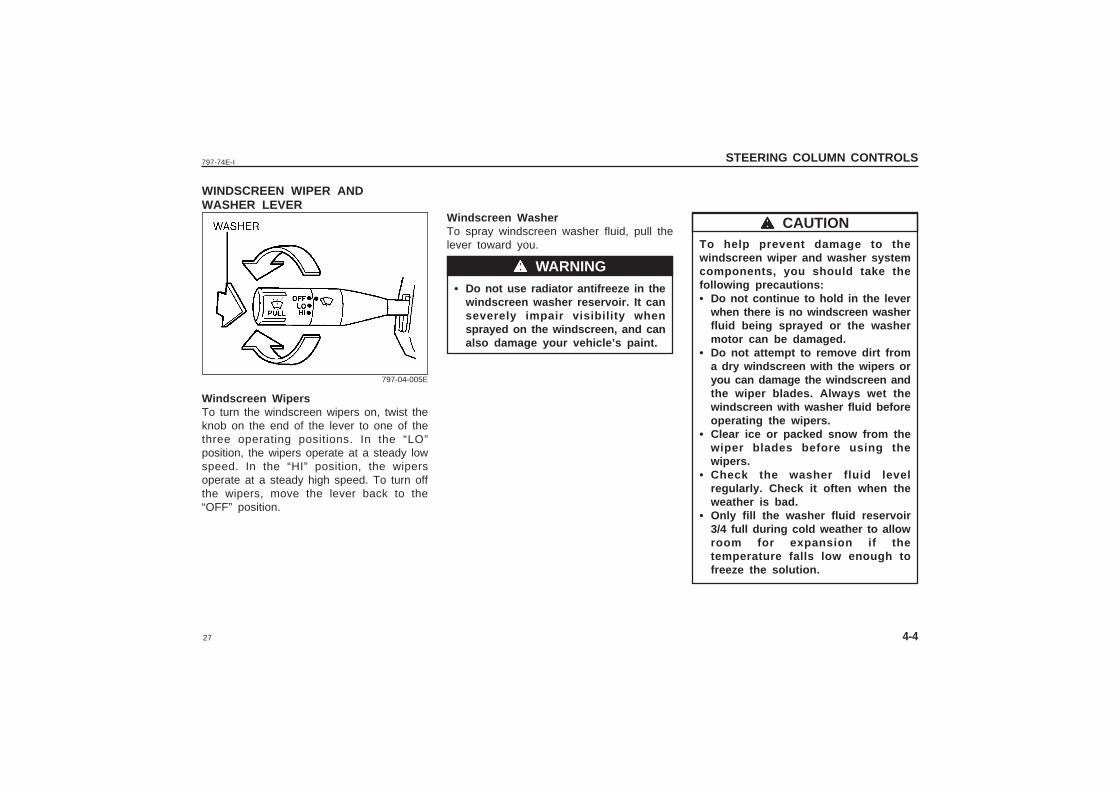
WINDSCREEN WIPER ANDWASHER LEVER
Windscreen WasherTo spray windscreen washer fluid, pull thelever toward you.
• Do not use radiator antifreeze in thewindscreen washer reservoir. It canseverely impair visibility whensprayed on the windscreen, and canalso damage your vehicle’s paint.
Windscreen WipersTo turn the windscreen wipers on, twist theknob on the end of the lever to one of thethree operating positions. In the “LO”position, the wipers operate at a steady lowspeed. In the “HI” position, the wipersoperate at a steady high speed. To turn offthe wipers, move the lever back to the“OFF” position.
797-04-005E
To help prevent damage to thewindscreen wiper and washer systemcomponents, you should take thefollowing precautions:• Do not continue to hold in the lever
when there is no windscreen washerfluid being sprayed or the washermotor can be damaged.
• Do not attempt to remove dirt froma dry windscreen with the wipers oryou can damage the windscreen andthe wiper blades. Always wet thewindscreen with washer fluid beforeoperating the wipers.
• Clear ice or packed snow from thewiper blades before using thewipers.
• Check the washer fluid levelregularly. Check it often when theweather is bad.
• Only fill the washer fluid reservoir3/4 full during cold weather to allowroom for expansion if thetemperature falls low enough tofreeze the solution.
wwwww WARNING
wwwww CAUTION
28
797-74E-ISTEERING COLUMN CONTROLS
4-5
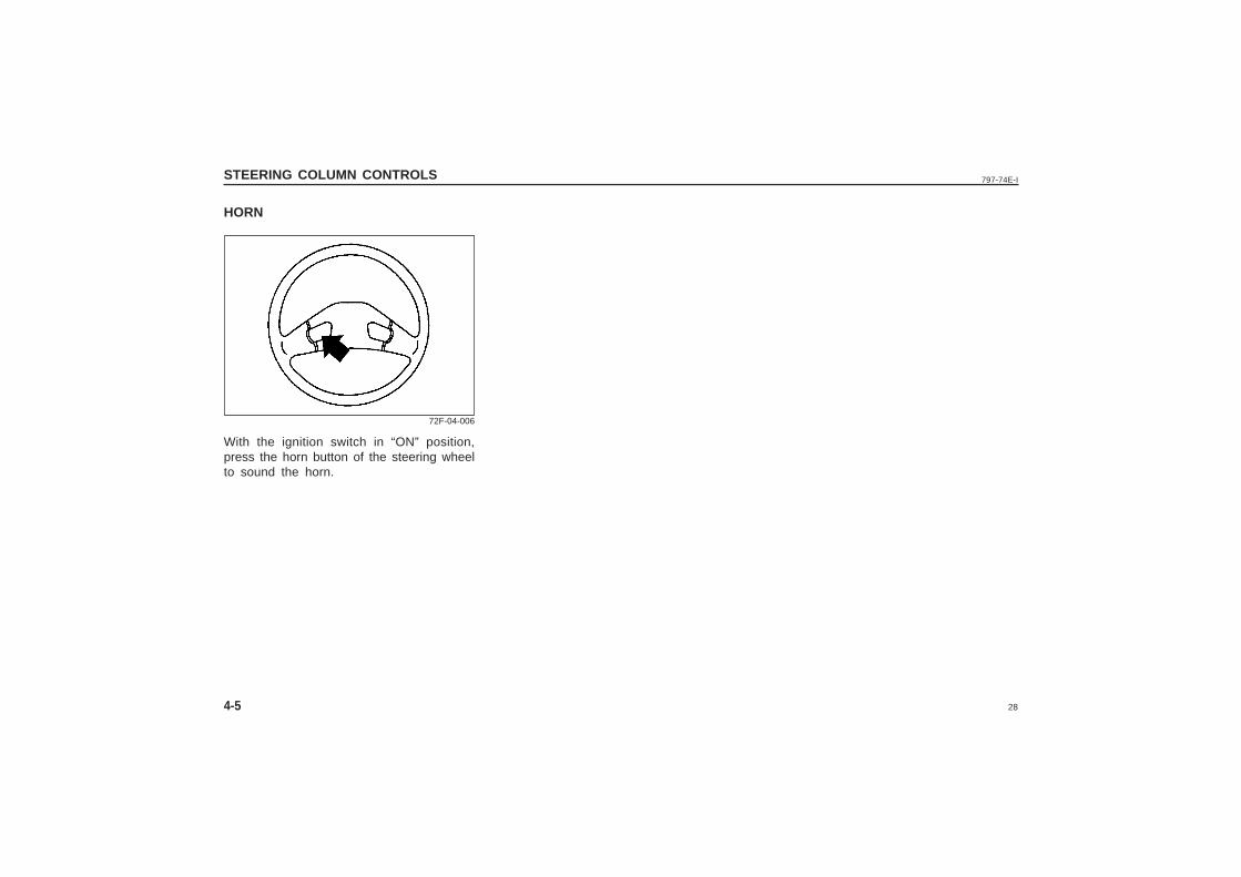
HORN
With the ignition switch in “ON” position,press the horn button of the steering wheelto sound the horn.
72F-04-006
29
797-74E-I
5
INSTRUMENT PANEL
INSTRUMENT PANEL
Warning and Indicator Lights ..........................................................................5-3
Speedometer/Odometer ...................................................................................... 5-5
Fuel Gauge ..........................................................................................................5-6
Temperature Gauge ............................................................................................ 5-6
Cigarette Lighter (if equipped) ........................................................................ 5-6
Ashtray ..................................................................................................................5-7
Glove Box ............................................................................................................5-7
30
797-74E-IINSTRUMENT PANEL
5-1
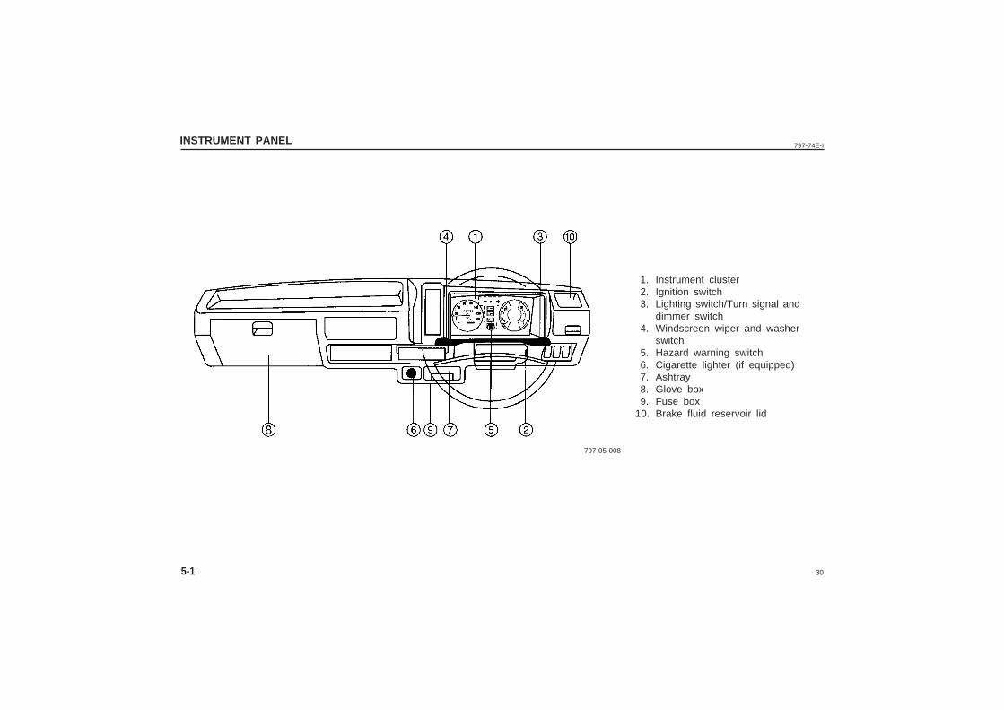
1. Instrument cluster2. Ignition switch3. Lighting switch/Turn signal and
dimmer switch4. Windscreen wiper and washer
switch5. Hazard warning switch6. Cigarette lighter (if equipped)7. Ashtray8. Glove box
9. Fuse box10. Brake fluid reservoir lid
797-05-008
31
797-74E-I INSTRUMENT PANEL
5-2
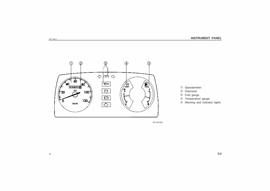
1 Speedometer2 Odometer3 Fuel gauge4 Temperature gauge5 Warning and indicator lights
797-05-009
32
797-74E-IINSTRUMENT PANEL
5-3
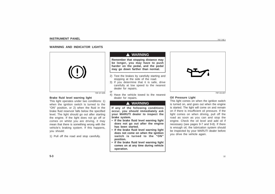
WARNING AND INDICATOR LIGHTS
Brake fluid level warning lightThis light operates under two conditions: 1)when the ignition switch is turned to the“ON” position, or 2) when the fluid in thebrake fluid reservoir falls below the specifiedlevel. The light should go out after startingthe engine. If the light does not go off orcomes on whilst you are driving, it maymean that there is something wrong with thevehicle’s braking system. If this happens,you should:
1) Pull off the road and stop carefully.
Remember that stopping distance maybe longer, you may have to pushharder on the pedal, and the pedalmay go down farther than normal.
2) Test the brakes by carefully starting andstopping at the side of the road.
3) If you determine that it is safe, drivecarefully at low speed to the nearestdealer for repairs.
or4) Have the vehicle towed to the nearest
dealer for repairs.
If any of the following conditionsoccur, you should immediately askyour MARUTI dealer to inspect thebrake system.• If the brake fluid level warning light
does not go out after the enginehas been started.
• If the brake fluid level warning lightdoes not come on when the ignitionswitch is turned to the “ON”position.
• If the brake fluid level warning lightcomes on at any time during vehicleoperation.
wwwww WARNING
wwwww WARNING
70F-07-029
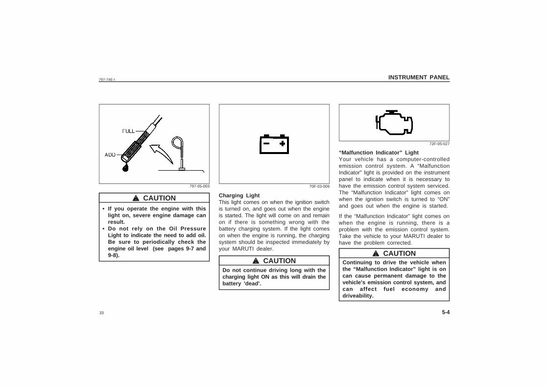
Oil Pressure LightThis light comes on when the ignition switchis turned on, and goes out when the engineis started. The light will come on and remainon if there is insufficient oil pressure. If thelight comes on when driving, pull off theroad as soon as you can and stop theengine. Check the oil level and add oil ifnecessary (see pages 9-7 and 9-8). If thereis enough oil, the lubrication system shouldbe inspected by your MARUTI dealer beforeyou drive the vehicle again.
70F-03-007
33
797-74E-I INSTRUMENT PANEL
5-4
• If you operate the engine with thislight on, severe engine damage canresult.
• Do not rely on the Oil PressureLight to indicate the need to add oil.Be sure to periodically check theengine oil level (see pages 9-7 and9-8).
wwwww CAUTION
797-05-003
Charging LightThis light comes on when the ignition switchis turned on, and goes out when the engineis started. The light will come on and remainon if there is something wrong with thebattery charging system. If the light comeson when the engine is running, the chargingsystem should be inspected immediately byyour MARUTI dealer.
Do not continue driving long with thecharging light ON as this will drain thebattery 'dead'.
70F-03-009
72F-05-027
“Malfunction Indicator” LightYour vehicle has a computer-controlledemission control system. A “MalfunctionIndicator” light is provided on the instrumentpanel to indicate when it is necessary tohave the emission control system serviced.The “Malfunction Indicator” light comes onwhen the ignition switch is turned to “ON”and goes out when the engine is started.
If the “Malfunction Indicator” light comes onwhen the engine is running, there is aproblem with the emission control system.Take the vehicle to your MARUTI dealer tohave the problem corrected.
Continuing to drive the vehicle whenthe “Malfunction Indicator” light is oncan cause permanent damage to thevehicle’s emission control system, andcan affect fuel economy anddriveability.
wwwww CAUTIONwwwww CAUTION
34
797-74E-IINSTRUMENT PANEL
5-5
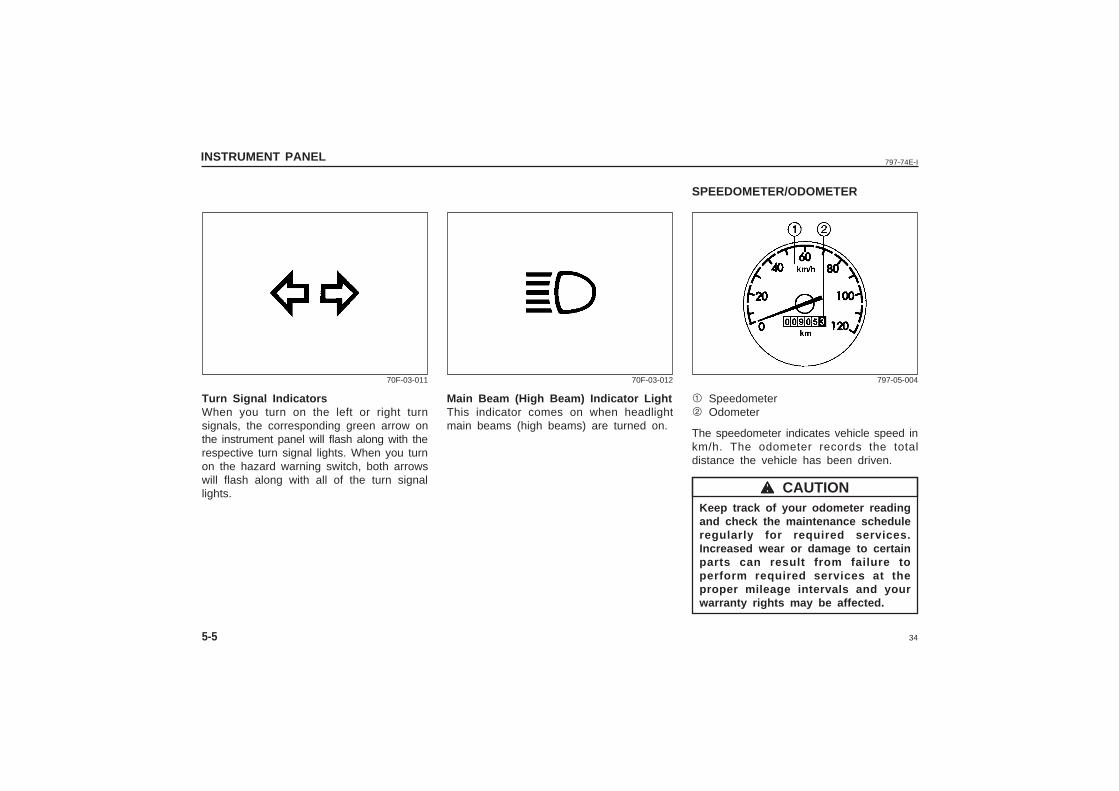
Main Beam (High Beam) Indicator LightThis indicator comes on when headlightmain beams (high beams) are turned on.
70F-03-012
SPEEDOMETER/ODOMETER
1 Speedometer2 Odometer
The speedometer indicates vehicle speed inkm/h. The odometer records the totaldistance the vehicle has been driven.
Keep track of your odometer readingand check the maintenance scheduleregularly for required services.Increased wear or damage to certainparts can result from failure toperform required services at theproper mileage intervals and yourwarranty rights may be affected.
797-05-004
wwwww CAUTION
Turn Signal IndicatorsWhen you turn on the left or right turnsignals, the corresponding green arrow onthe instrument panel will flash along with therespective turn signal lights. When you turnon the hazard warning switch, both arrowswill flash along with all of the turn signallights.
70F-03-011
35
797-74E-I INSTRUMENT PANEL
5-6
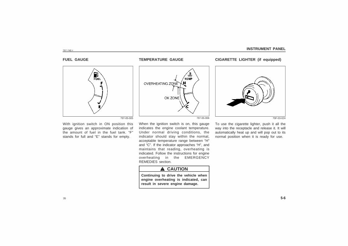
TEMPERATURE GAUGE
When the ignition switch is on, this gaugeindicates the engine coolant temperature.Under normal driving conditions, theindicator should stay within the normal,acceptable temperature range between “H”and “C”. If the indicator approaches “H”, andmaintains that reading, overheating isindicated. Follow the instructions for engineoverheating in the EMERGENCYREMEDIES section.
Continuing to drive the vehicle whenengine overheating is indicated, canresult in severe engine damage.
CIGARETTE LIGHTER (if equipped)
To use the cigarette lighter, push it all theway into the receptacle and release it. It willautomatically heat up and will pop out to itsnormal position when it is ready for use.
wwwww CAUTION
797-05-006 70F-03-024
FUEL GAUGE
With ignition switch in ON position thisgauge gives an approximate indication ofthe amount of fuel in the fuel tank. “F”stands for full and “E” stands for empty.
797-05-005
36
797-74E-IINSTRUMENT PANEL
5-7
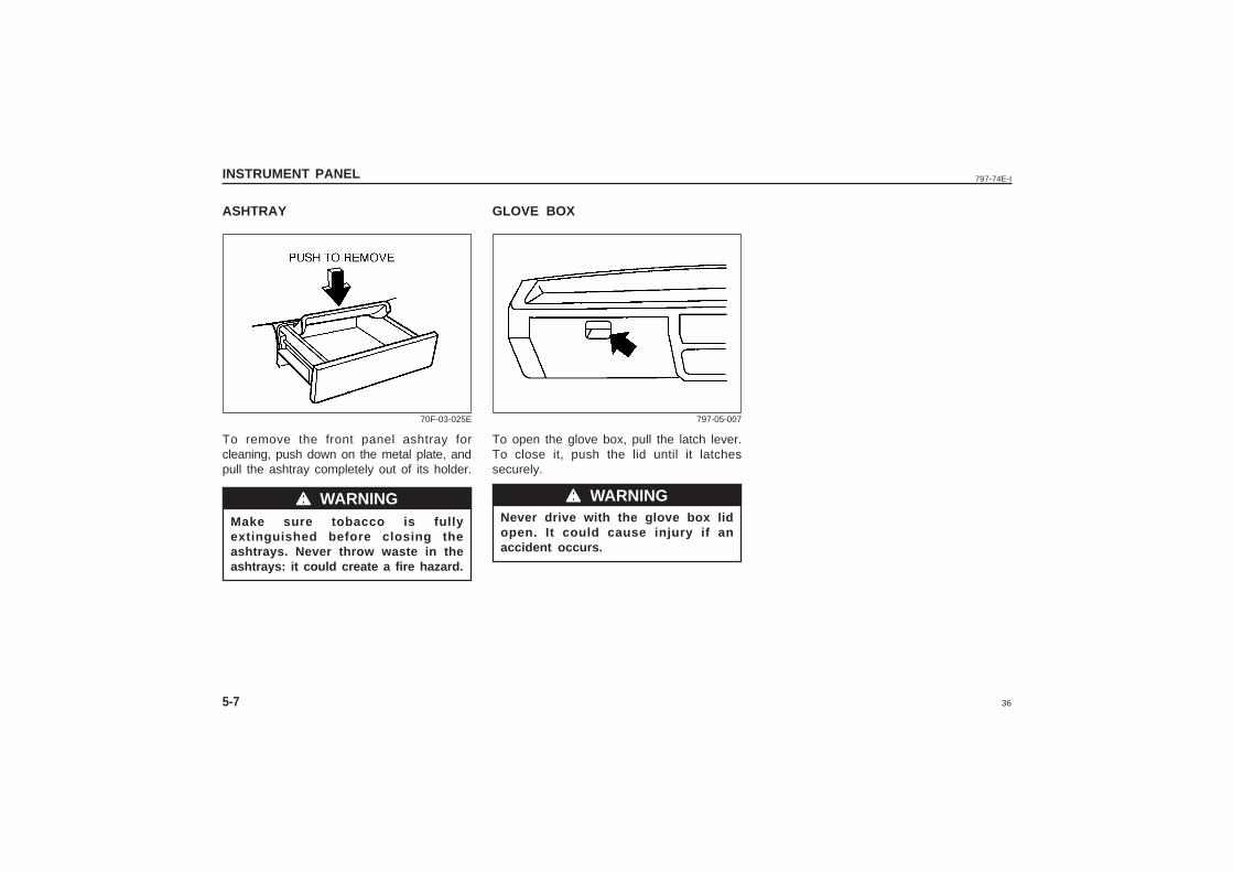
ASHTRAY
To remove the front panel ashtray forcleaning, push down on the metal plate, andpull the ashtray completely out of its holder.
Make sure tobacco is fullyextinguished before closing theashtrays. Never throw waste in theashtrays: it could create a fire hazard.
GLOVE BOX
To open the glove box, pull the latch lever.To close it, push the lid until it latchessecurely.
Never drive with the glove box lidopen. It could cause injury if anaccident occurs.
wwwww WARNING
70F-03-025E 797-05-007
wwwww WARNING
37
797-74E-I
MEMO
38
797-74E-I
MEMO
39
797-74E-I OTHER CONTROLS AND EQUIPMENT
6
OTHER CONTROLS AND EQUIPMENT
Parking Brake Lever .......................................................................................... 6-1
Pedals ...................................................................................................................6-2
Gear Lever ...........................................................................................................6-2
Fuel Filler Cap ....................................................................................................6-3
Front Seats Removal ......................................................................................... 6-4
Luggage Compartment ...................................................................................... 6-4
Sun Visor ............................................................................................................. 6-5
Ventilator .............................................................................................................. 6-5
Interior Light Switchs ........................................................................................6-5
Assist Grips .........................................................................................................6-6
Tyre Changing Tools ......................................................................................... 6-6
40
797-74E-I
6-1
OTHER CONTROLS AND EQUIPMENT
PARKING BRAKE LEVER
Always apply the parking brake fullybefore leaving your vehicle or it maymove, causing injury or damage.When parking, make sure the gearshift lever is left in first gear orreverse. Remember, even though thetransmission is in gear, you mustalways apply the parking brake fully.
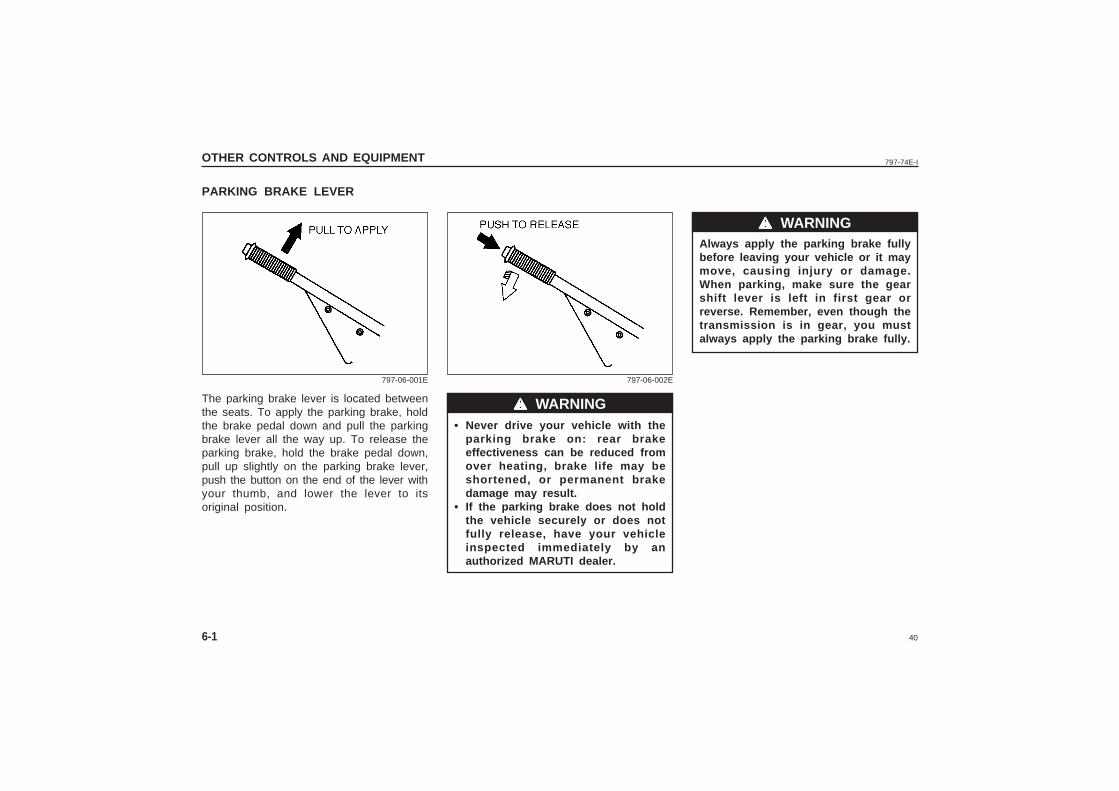
The parking brake lever is located betweenthe seats. To apply the parking brake, holdthe brake pedal down and pull the parkingbrake lever all the way up. To release theparking brake, hold the brake pedal down,pull up slightly on the parking brake lever,push the button on the end of the lever withyour thumb, and lower the lever to itsoriginal position.
wwwww WARNING
wwwww WARNING
• Never drive your vehicle with theparking brake on: rear brakeeffectiveness can be reduced fromover heating, brake life may beshortened, or permanent brakedamage may result.
• If the parking brake does not holdthe vehicle securely or does notfully release, have your vehicleinspected immediately by anauthorized MARUTI dealer.
797-06-001E 797-06-002E
41
797-74E-I
6-2
OTHER CONTROLS AND EQUIPMENT
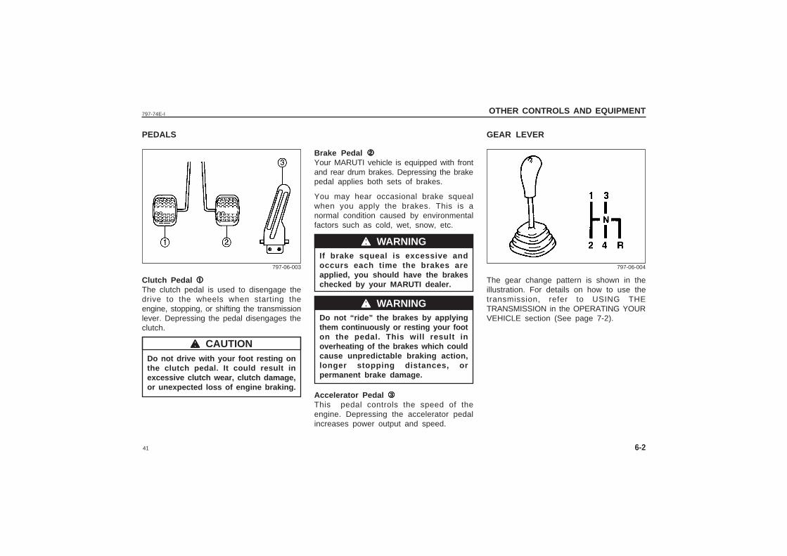
PEDALS
Clutch Pedal 11111The clutch pedal is used to disengage thedrive to the wheels when starting theengine, stopping, or shifting the transmissionlever. Depressing the pedal disengages theclutch.
Do not drive with your foot resting onthe clutch pedal. It could result inexcessive clutch wear, clutch damage,or unexpected loss of engine braking.
Brake Pedal 22222Your MARUTI vehicle is equipped with frontand rear drum brakes. Depressing the brakepedal applies both sets of brakes.
You may hear occasional brake squealwhen you apply the brakes. This is anormal condition caused by environmentalfactors such as cold, wet, snow, etc.
If brake squeal is excessive andoccurs each time the brakes areapplied, you should have the brakeschecked by your MARUTI dealer.
Do not “ride” the brakes by applyingthem continuously or resting your footon the pedal. This will result inoverheating of the brakes which couldcause unpredictable braking action,longer stopping distances, orpermanent brake damage.
Accelerator Pedal 33333This pedal controls the speed of theengine. Depressing the accelerator pedalincreases power output and speed.
wwwww CAUTION
797-06-003 797-06-004
GEAR LEVER
The gear change pattern is shown in theillustration. For details on how to use thetransmission, refer to USING THETRANSMISSION in the OPERATING YOURVEHICLE section (See page 7-2).
wwwww WARNING
wwwww WARNING
42
797-74E-I
6-3
OTHER CONTROLS AND EQUIPMENT
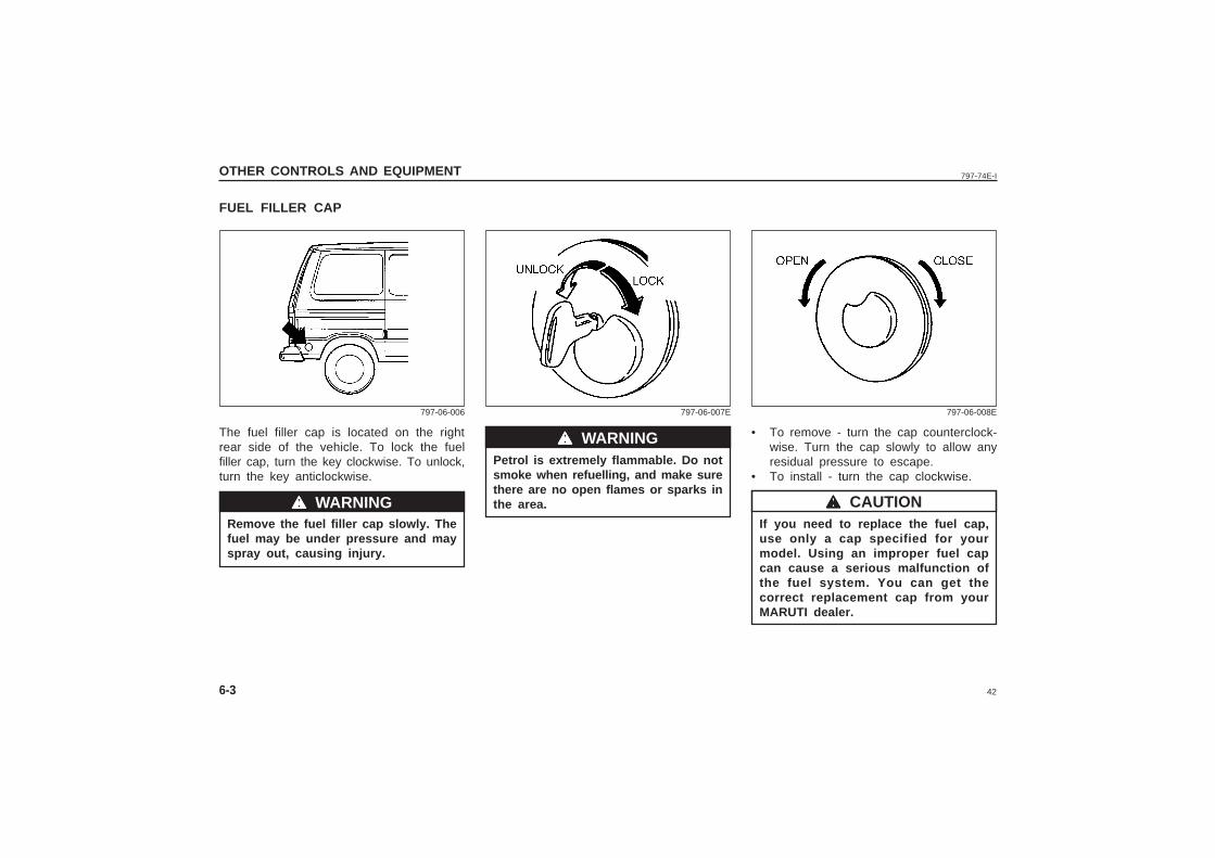
FUEL FILLER CAP
The fuel filler cap is located on the rightrear side of the vehicle. To lock the fuelfiller cap, turn the key clockwise. To unlock,turn the key anticlockwise.
Remove the fuel filler cap slowly. Thefuel may be under pressure and mayspray out, causing injury.
wwwww WARNING
Petrol is extremely flammable. Do notsmoke when refuelling, and make surethere are no open flames or sparks inthe area.
• To remove - turn the cap counterclock-wise. Turn the cap slowly to allow anyresidual pressure to escape.
• To install - turn the cap clockwise.
If you need to replace the fuel cap,use only a cap specified for yourmodel. Using an improper fuel capcan cause a serious malfunction ofthe fuel system. You can get thecorrect replacement cap from yourMARUTI dealer.
wwwww WARNING
wwwww CAUTION
797-06-006 797-06-007E 797-06-008E
43
797-74E-I
6-4
OTHER CONTROLS AND EQUIPMENT
797-03-008
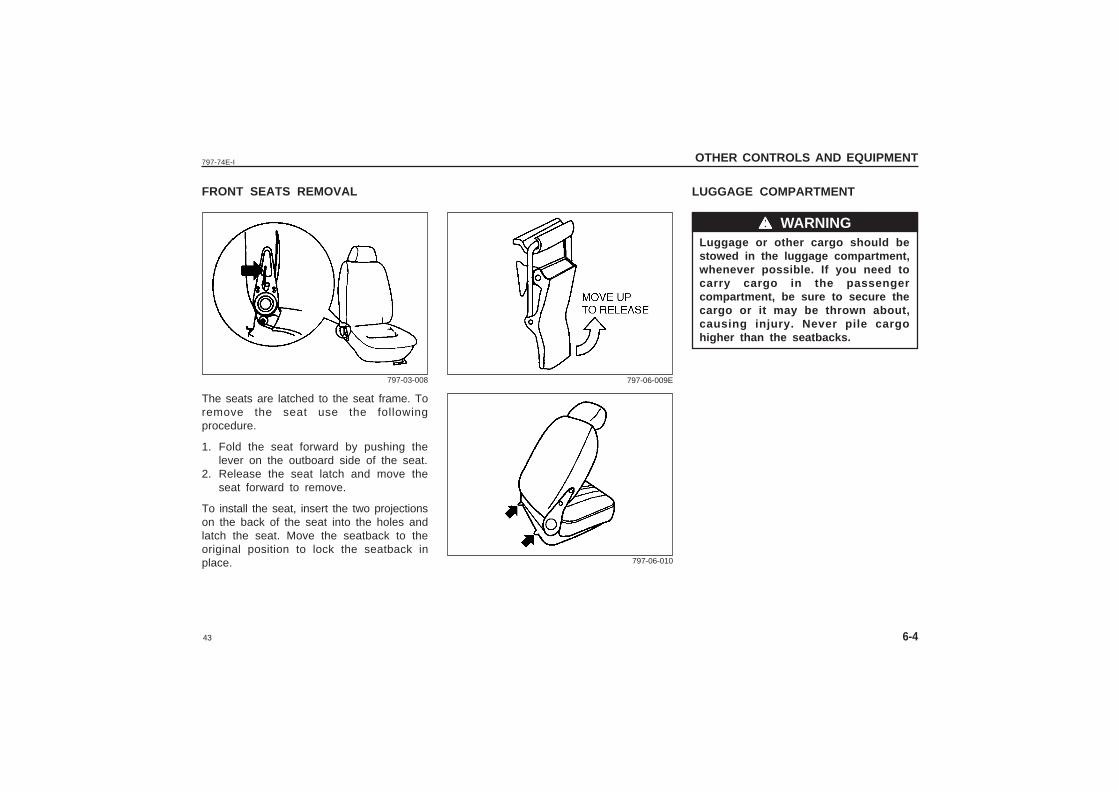
FRONT SEATS REMOVAL LUGGAGE COMPARTMENT
The seats are latched to the seat frame. Toremove the seat use the followingprocedure.
1. Fold the seat forward by pushing thelever on the outboard side of the seat.
2. Release the seat latch and move theseat forward to remove.
To install the seat, insert the two projectionson the back of the seat into the holes andlatch the seat. Move the seatback to theoriginal position to lock the seatback inplace.
wwwww WARNING
797-06-010
Luggage or other cargo should bestowed in the luggage compartment,whenever possible. If you need tocarry cargo in the passengercompartment, be sure to secure thecargo or it may be thrown about,causing injury. Never pile cargohigher than the seatbacks.
797-06-009E
44
797-74E-I
6-5
OTHER CONTROLS AND EQUIPMENT
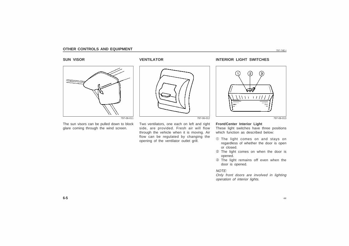
SUN VISOR INTERIOR LIGHT SWITCHES
The sun visors can be pulled down to blockglare coming through the wind screen.
Front/Center Interior LightThese light switches have three positionswhich function as described below:
1 The light comes on and stays onregardless of whether the door is openor closed.
2 The light comes on when the door isopened.
3 The light remains off even when thedoor is opened.
NOTE:Only front doors are involved in lightingoperation of interior lights.
797-06-011 797-06-012 797-06-013
VENTILATOR
Two ventilators, one each on left and rightside, are provided. Fresh air will flowthrough the vehicle when it is moving. Airflow can be regulated by changing theopening of the ventilator outlet grill.
45
797-74E-I
6-6
OTHER CONTROLS AND EQUIPMENT
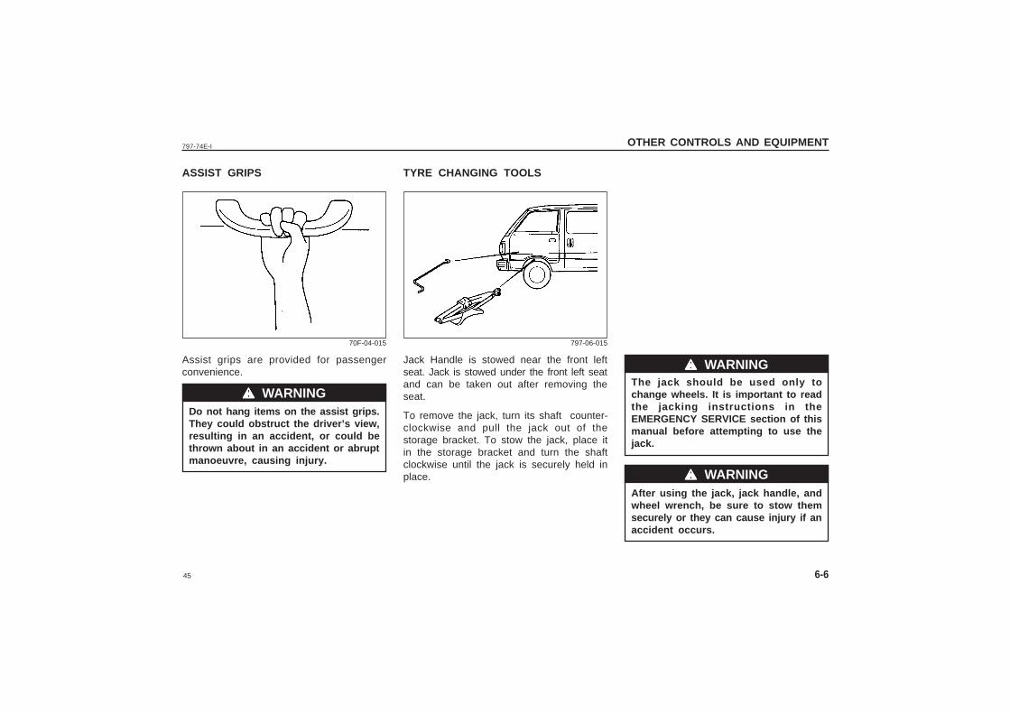
ASSIST GRIPS
Assist grips are provided for passengerconvenience.
Do not hang items on the assist grips.They could obstruct the driver’s view,resulting in an accident, or could bethrown about in an accident or abruptmanoeuvre, causing injury.
wwwww WARNING
70F-04-015
TYRE CHANGING TOOLS
Jack Handle is stowed near the front leftseat. Jack is stowed under the front left seatand can be taken out after removing theseat.
To remove the jack, turn its shaft counter-clockwise and pull the jack out of thestorage bracket. To stow the jack, place itin the storage bracket and turn the shaftclockwise until the jack is securely held inplace.
The jack should be used only tochange wheels. It is important to readthe jacking instructions in theEMERGENCY SERVICE section of thismanual before attempting to use thejack.
After using the jack, jack handle, andwheel wrench, be sure to stow themsecurely or they can cause injury if anaccident occurs.
wwwww WARNING
wwwww WARNING
797-06-015

46
797-74E-I
47
797-74E-I OPERATING YOUR VEHICLE
7
OPERATING YOUR VEHICLE
Exhaust Gas Warning ....................................................................................... 7-1
Daily Inspection Checklist ................................................................................ 7-1
Starting the Engine ............................................................................................ 7-2
Using the Transmission .................................................................................... 7-3
Braking ..................................................................................................................7-4
Running-in ............................................................................................................7-4
Catalytic Converter ............................................................................................. 7-5
Improving Fuel Economy ................................................................................. 7-6
Trailer Towing .....................................................................................................7-6
48
797-74E-I
7-1
OPERATING YOUR VEHICLE
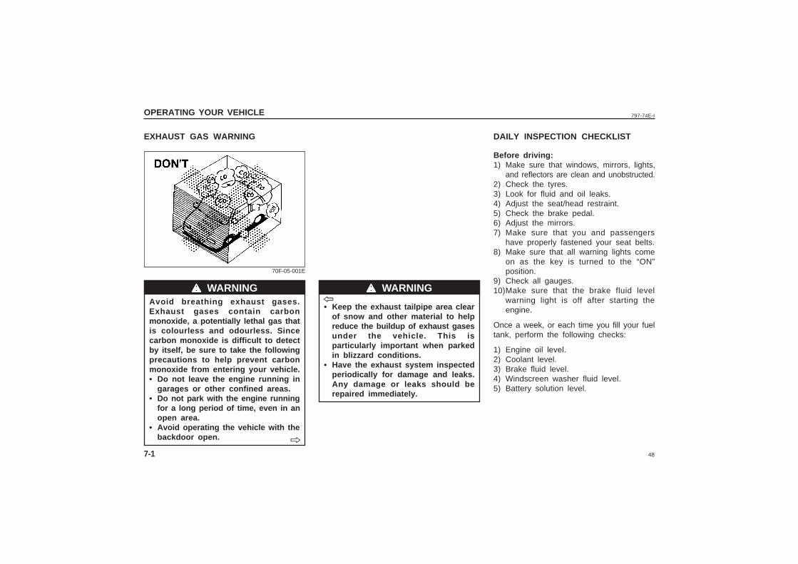
EXHAUST GAS WARNING
• Keep the exhaust tailpipe area clearof snow and other material to helpreduce the buildup of exhaust gasesunder the vehicle. This isparticularly important when parkedin blizzard conditions.
• Have the exhaust system inspectedperiodically for damage and leaks.Any damage or leaks should berepaired immediately.
DAILY INSPECTION CHECKLIST
wwwww WARNING wwwww WARNINGAvoid breathing exhaust gases.Exhaust gases contain carbonmonoxide, a potentially lethal gas thatis colourless and odourless. Sincecarbon monoxide is difficult to detectby itself, be sure to take the followingprecautions to help prevent carbonmonoxide from entering your vehicle.• Do not leave the engine running in
garages or other confined areas.• Do not park with the engine running
for a long period of time, even in anopen area.
• Avoid operating the vehicle with thebackdoor open.
70F-05-001E
ˇ̌̌̌̌
ˇ̌̌̌̌
Before driving:1) Make sure that windows, mirrors, lights,
and reflectors are clean and unobstructed.2) Check the tyres.3) Look for fluid and oil leaks.4) Adjust the seat/head restraint.5) Check the brake pedal.6) Adjust the mirrors.7) Make sure that you and passengers
have properly fastened your seat belts.8) Make sure that all warning lights come
on as the key is turned to the “ON”position.
9) Check all gauges.10)Make sure that the brake fluid level
warning light is off after starting theengine.
Once a week, or each time you fill your fueltank, perform the following checks:
1) Engine oil level.2) Coolant level.3) Brake fluid level.4) Windscreen washer fluid level.5) Battery solution level.
49
797-74E-I
7-2
OPERATING YOUR VEHICLE
wwwww CAUTION
wwwww WARNING
Starting a Cold EngineEngine which is started after 6 hours shouldbe treated as cold engine.
For Electronic fuel injection models• With your foot off the accelerator pedal,
crank the engine by turning the ignitionkey to “START”. Release the key whenthe engine starts.
• If the engine does not start after 15seconds of cranking, wait about 15seconds, then press down theaccelerator pedal to 1/3 of its travel andtry cranking the engine again. Releasethe key and accelerator pedal when theengine starts.
• If the engine still does not start, tryholding the accelerator pedal all the wayto the floor while cranking. This shouldclear the engine if it is flooded.
Starting a Warm Engine
For Electronic fuel injection models:Use the same procedure as for “Starting acold Engine”.
STARTING THE ENGINE
Before starting the engine:1) Make sure the parking brake is applied
fully.2) Shift into “N” (neutral) and depress the
clutch pedal all the way to the floor. Holdit while starting the engine.
Make sure that the parking brake isapplied fully and the transmission isin Neutral before attempting to startthe engine.
• Stop turning the starter immediatelyafter the engine has started or thestarter system can be damaged.
• Do not crank the engine for morethan 15 seconds at a time. If theengine doesn’t start on the first try,wait about 15 seconds before tryingagain.
50
797-74E-I
7-3
OPERATING YOUR VEHICLE
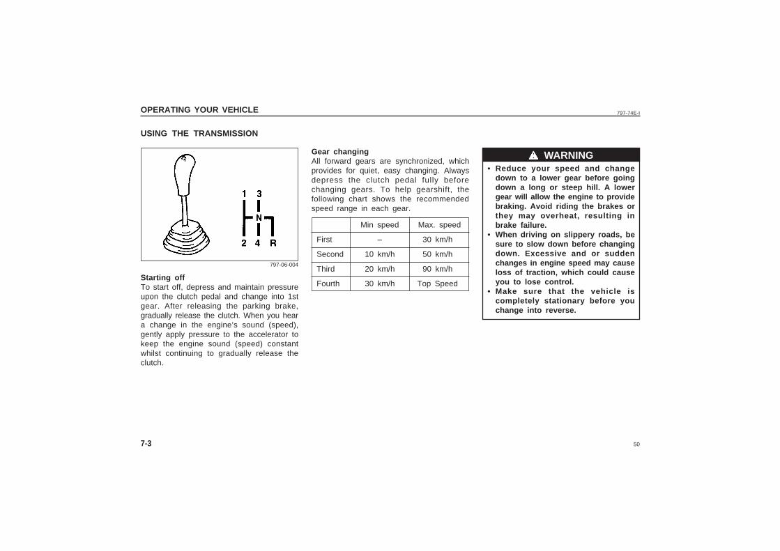
• Reduce your speed and changedown to a lower gear before goingdown a long or steep hill. A lowergear will allow the engine to providebraking. Avoid riding the brakes orthey may overheat, resulting inbrake failure.
• When driving on slippery roads, besure to slow down before changingdown. Excessive and or suddenchanges in engine speed may causeloss of traction, which could causeyou to lose control.
• Make sure that the vehicle iscompletely stationary before youchange into reverse.
wwwww WARNING
USING THE TRANSMISSION
Starting offTo start off, depress and maintain pressureupon the clutch pedal and change into 1stgear. After releasing the parking brake,gradually release the clutch. When you heara change in the engine’s sound (speed),gently apply pressure to the accelerator tokeep the engine sound (speed) constantwhilst continuing to gradually release theclutch.
797-06-004
Min speed Max. speed
First – 30 km/h
Second 10 km/h 50 km/h
Third 20 km/h 90 km/h
Fourth 30 km/h Top Speed
Gear changingAll forward gears are synchronized, whichprovides for quiet, easy changing. Alwaysdepress the clutch pedal fully beforechanging gears. To help gearshift, thefollowing chart shows the recommendedspeed range in each gear.
51
797-74E-I
7-4
OPERATING YOUR VEHICLE
RUNNING-IN
The future performance and reliabilityof the engine depends on the careand restraint exercised during its earlylife. It is especially important toobserve the following precautionsduring the initial 1000 km of vehicleoperation.• After starting, do not race the
engine. Warm it up gradually.• Avoid prolonged vehicle operation at
a constant speed. Moving parts willbed in better if you vary your speed.
• Do not exceed 90 km/h.• Start off from a stop slowly. Avoid
full throttle starts.• If possible, avoid hard braking,
especially during the first 300 kmof driving.
• Do not drive slowly with thetransmission in a high gear.
• Drive the vehicle at moderate enginespeeds.
wwwww CAUTIONwwwww CAUTION• To help avoid clutch damage, do not
use the clutch pedal as a footrestwhile driving or use the clutch tokeep the vehicle stationary on a hill.Depress the clutch fully whenchanging gear.
• When changing gears or starting off,do not race the engine. Racing theengine can shorten engine life andprevent smooth operation.
BRAKING
The distance needed to bring any vehicleto a halt increases with the speed of thevehicle. The braking distance needed, forexample, at 60 km/h will be approximately4 times greater than the braking distanceneeded at 20 km/h. Start to brake thevehicle when there is plenty of distancebetween your vehicle and the stopping point,and slow down gradually.
If water gets into the brake drums,brake performance may become poorand unpredictable. After drivingthrough water or washing theunderside of the vehicle, test thebrakes while driving at a slow speedto see if they have maintained theirnormal effectiveness. If the brakes areless effective than normal, dry themby repeatedly applying the brakeswhile driving slowly until the brakeshave regained their normaleffectiveness.
wwwww WARNING
52
797-74E-I
7-5
OPERATING YOUR VEHICLE
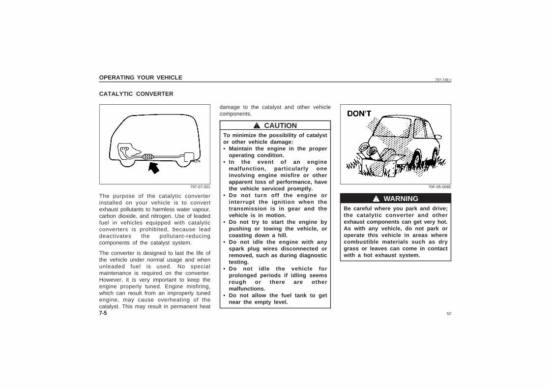
Be careful where you park and drive;the catalytic converter and otherexhaust components can get very hot.As with any vehicle, do not park oroperate this vehicle in areas wherecombustible materials such as drygrass or leaves can come in contactwith a hot exhaust system.
wwwww WARNING
70F-05-006E
CATALYTIC CONVERTER
The purpose of the catalytic converterinstalled on your vehicle is to convertexhaust pollutants to harmless water vapour,carbon dioxide, and nitrogen. Use of leadedfuel in vehicles equipped with catalyticconverters is prohibited, because leaddeactivates the pollutant-reducingcomponents of the catalyst system.
The converter is designed to last the life ofthe vehicle under normal usage and whenunleaded fuel is used. No specialmaintenance is required on the converter.However, it is very important to keep theengine properly tuned. Engine misfiring,which can result from an improperly tunedengine, may cause overheating of thecatalyst. This may result in permanent heat
damage to the catalyst and other vehiclecomponents.
To minimize the possibility of catalystor other vehicle damage:• Maintain the engine in the proper
operating condition.• In the event of an engine
malfunction, particularly oneinvolving engine misfire or otherapparent loss of performance, havethe vehicle serviced promptly.
• Do not turn off the engine orinterrupt the ignition when thetransmission is in gear and thevehicle is in motion.
• Do not try to start the engine bypushing or towing the vehicle, orcoasting down a hill.
• Do not idle the engine with anyspark plug wires disconnected orremoved, such as during diagnostictesting.
• Do not idle the vehicle forprolonged periods if idling seemsrough or there are othermalfunctions.
• Do not allow the fuel tank to getnear the empty level.
wwwww CAUTION
797-07-001
53
797-74E-I
TRAILER TOWING
Your MARUTI was originally designed tocarry people and a normal amount of cargo,not to tow a trailer. Maruti does notrecommend you use your vehicle to tow atrailer. Towing a trailer can adversely affecthandling, durability, and fuel economy.
OPERATING YOUR VEHICLE
7-6
IMPROVING FUEL ECONOMY
The following instructions will help youimprove fuel economy.
Avoid excessive idling:If you are to wait for more than a minutewhile you are parked, stop the engine andstart it again later. When warming up a coldengine, allow the engine to idle until thetemperature gauge pointer comes up to the“C” position. In this position, the engine issufficiently warm for starting off.
Avoid “fast” starts:Fast starts away from lights or stop signswill consume fuel unnecessarily and shortenengine life. Start off slowly.
Avoid unnecessary stops:Avoid unnecessary deceleration andstopping. Try to maintain a slow, steadyspeed whenever possible. Slowing downand then accelerating again uses more fuel.
Keep a steady cruising speed:Keep as constant a speed as road andtraffic conditions will permit.
Keep the air cleaner clean:A dirty air cleaner will cause the carburationsystem to supply too much fuel to theengine for the amount of air being supplied.The result is waste of fuel due to incompletecombustion.
Keep weight to a minimum:The heavier the load, the more fuel thevehicle consumes. Take out any luggage orcargo when it is not necessary.
Keep tyre pressures correct:Under-inflation of the tyres can waste fueldue to increased running resistance of thetyres. Keep your tyres inflated to the correctpressure shown on the label on the driver’sside door or door lock pillar.

54
797-74E-I
55
797-74E-I DRIVING TIPS AND SAFE DRIVING
8
DRIVING TIPS AND SAFE DRIVING
High Speed Driving ........................................................................................... 8-1
Driving on Hills .................................................................................................. 8-1
Driving on Slippery Roads .............................................................................. 8-2
Do’s and Don’ts for Safe Driving .................................................................. 8-3
56
797-74E-I
8-1
DRIVING TIPS AND SAFE DRIVING
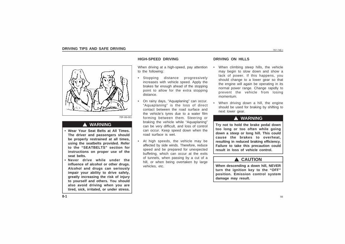
• Wear Your Seat Belts at All Times.The driver and passengers shouldbe properly restrained at all times,using the seatbelts provided. Referto the “SEATBELTS” section forinstructions on proper use of theseat belts.
• Never drive while under theinfluence of alcohol or other drugs.Alcohol and drugs can seriouslyimpair your ability to drive safely,greatly increasing the risk of injuryto yourself and others. You shouldalso avoid driving when you aretired, sick, irritated, or under stress.
HIGH-SPEED DRIVING DRIVING ON HILLS
When driving at a high-speed, pay attentionto the following:
• Stopping distance progressivelyincreases with vehicle speed. Apply thebrakes far enough ahead of the stoppingpoint to allow for the extra stoppingdistance.
• On rainy days, “Aquaplaning” can occur.“Aquaplaning” is the loss of directcontact between the road surface andthe vehicle’s tyres due to a water filmforming between them. Steering orbraking the vehicle while “Aquaplaning”can be very difficult, and loss of controlcan occur. Keep speed down when theroad surface is wet.
• At high speeds, the vehicle may beaffected by side winds. Therefore, reducespeed and be prepared for unexpectedbuffeting, which can occur at the exitsof tunnels, when passing by a cut of ahill, or when being overtaken by largevehicles, etc.
• When climbing steep hills, the vehiclemay begin to slow down and show alack of power. If this happens, youshould change to a lower gear so thatthe engine will again be operating in itsnormal power range. Change rapidly toprevent the vehicle from losingmomentum.
• When driving down a hill, the engineshould be used for braking by shifting tonext lower gear.
Try not to hold the brake pedal downtoo long or too often while goingdown a steep or long hill. This couldcause the brakes to overheat,resulting in reduced braking efficiency.Failure to take this precaution couldresult in loss of vehicle control.
When descending a down hill, NEVERturn the ignition key to the “OFF”position. Emission control systemdamage may result.
wwwww WARNING
70F-06-001 wwwww WARNING
wwwww CAUTION
57
797-74E-I
8-2
DRIVING TIPS AND SAFE DRIVING
DRIVING ON SLIPPERY ROADS
Do not race the engine. Excessive wheelspin will cause the tyres to dig deeper,making it more difficult to free thevehicle.
2) If your vehicle remains stuck after a fewminutes of rocking, get another vehicleto pull you out.
Do not allow anyone to stand near thevehicle when you are rocking it, anddo not spin the wheels faster than anindicated 40 km/h on the speedometer.Personal injury and/or vehicle damagemay result from spinning the wheelstoo fast.
Do not continue rocking the vehiclefor more than a few minutes.Prolonged rocking can cause engineoverheating or transmission damage.
• Make sure your tyres are in goodcondition and always maintain thespecified tyre pressure. Refer to“TYRES” in the “INSPECTION ANDMAINTENANCE” section for details.
• Do not use tyres other than thosespecified by MARUTI. never usedifferent sizes or types of tyres onthe front and rear wheels. Forinformation regarding the specifiedtyres, refer to the “SPECI-FICATIONS” section.
• Never use oversized tyres or specialshock absorbers and springs toraise (jack up) your vehicle. This willchange the handling characteristics.
• After driving through water, test thebrakes while driving at a slow speedto see if they have maintained theirnormal effectiveness. If the brakesare less effective than normal, drythem by repeatedly applying thebrakes while driving slowly until thebrakes have regained their normaleffectiveness.
Under wet road conditions you should driveat a lower speed than on dry roads due topossible slippage of tyres during braking.When driving on icy, snowcovered, ormuddy roads, reduce your speed and avoidsudden acceleration, abrupt braking, orsharp steering movements.
Snow ChainsIf you must use snow chains to increasetyre traction, observe the followingprecautions:
• Choose a safe place away from trafficto install the chains.
• When installing the chains carefullyfollow the manufacturer’s instructions.
• Install the chains on the rear tyres.• With the chains on, drive only at slow
and moderate speeds.
• If Your Vehicle Gets StuckIf your vehicle gets stuck in snow, mud,or sand, follow the directions below:
1) Change back and forth between firstgear and reverse. This will create arocking motion which may give youenough momentum to free the vehicle.Press gently on the accelerator to keepwheel spin to a minimum. Remove yourfoot from the accelerator while changinggear.
wwwww WARNING
wwwww WARNING
wwwww CAUTION
58
797-74E-I
8-3
DRIVING TIPS AND SAFE DRIVING
DO’S AND DON’TS FOR SAFEDRIVINGExercise care in handling your vehicle. Beconscious of not only your own safety butalso the safety of others on the road, andthus enjoy the best and most comfortabledriving experience.
This section contains basic rules for safedriving. Read it carefully for goodunderstanding of the content so that youcan enjoy safe and pleasant driving in yourMaruti vehicle.
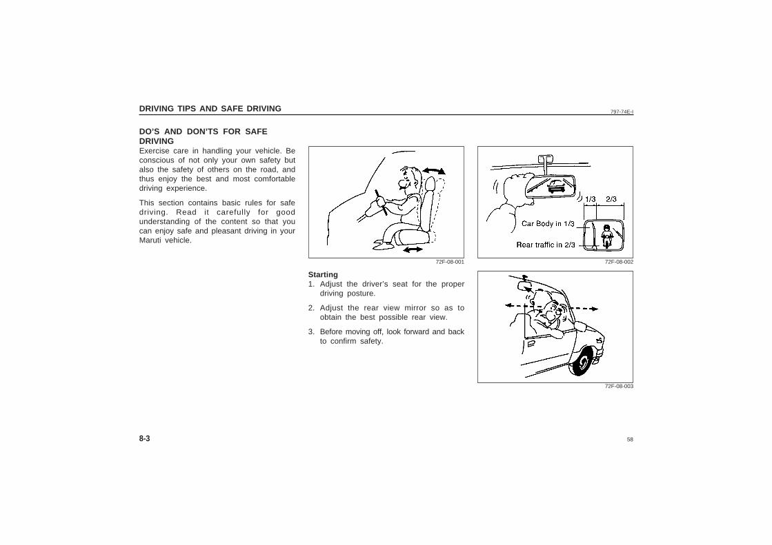
Starting1. Adjust the driver’s seat for the proper
driving posture.
2. Adjust the rear view mirror so as toobtain the best possible rear view.
3. Before moving off, look forward and backto confirm safety.
72F-08-001 72F-08-002
72F-08-003
59
797-74E-I
8-4
DRIVING TIPS AND SAFE DRIVING
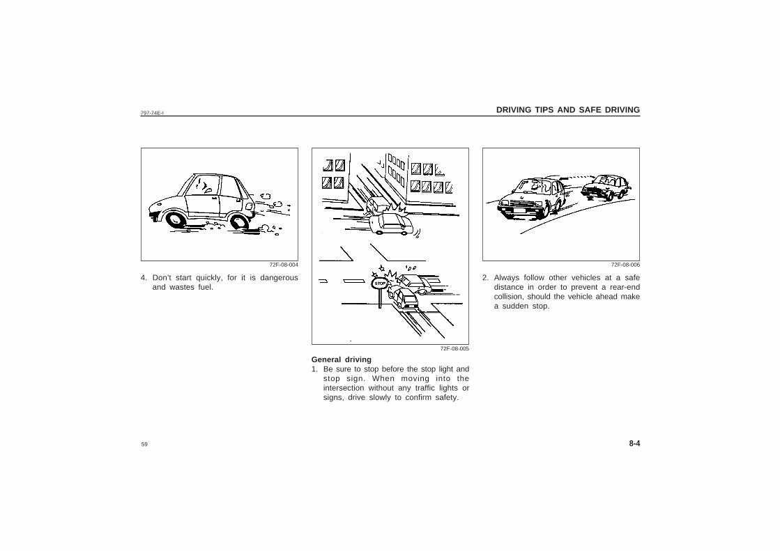
4. Don’t start quickly, for it is dangerousand wastes fuel.
General driving1. Be sure to stop before the stop light and
stop sign. When moving into theintersection without any traffic lights orsigns, drive slowly to confirm safety.
2. Always follow other vehicles at a safedistance in order to prevent a rear-endcollision, should the vehicle ahead makea sudden stop.
72F-08-004
72F-08-005
72F-08-006
60
797-74E-I
8-5
DRIVING TIPS AND SAFE DRIVING
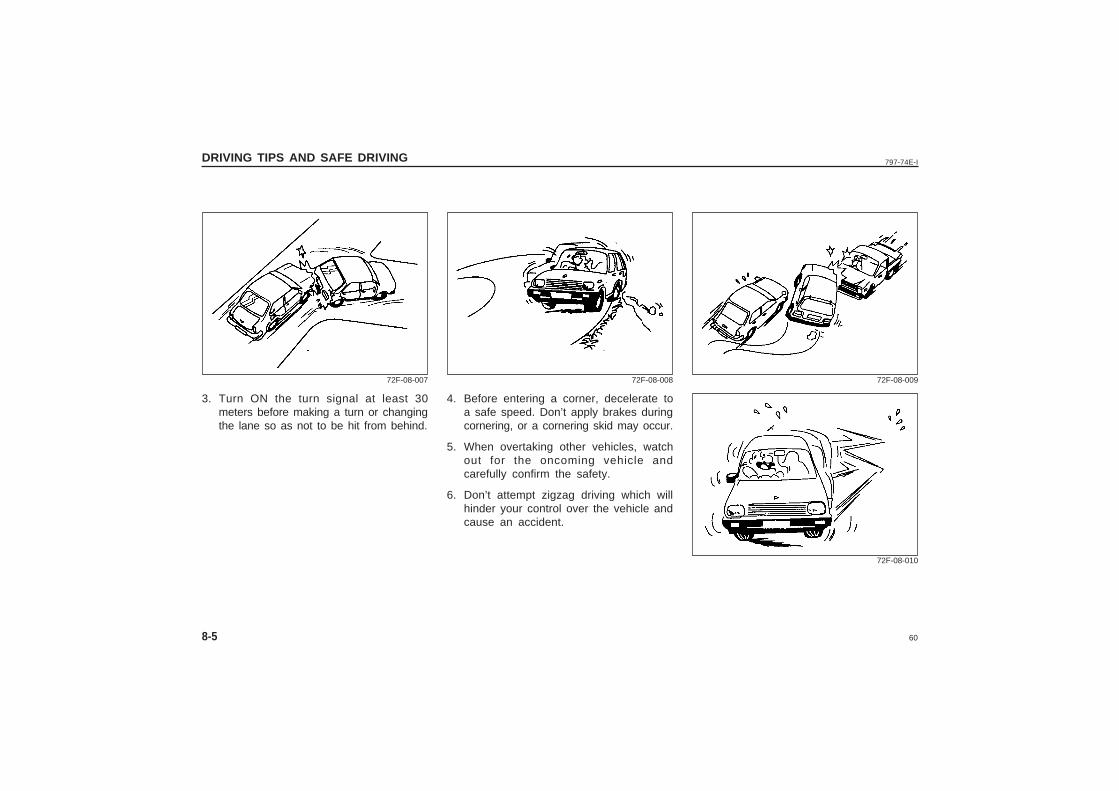
3. Turn ON the turn signal at least 30meters before making a turn or changingthe lane so as not to be hit from behind.
4. Before entering a corner, decelerate toa safe speed. Don’t apply brakes duringcornering, or a cornering skid may occur.
5. When overtaking other vehicles, watchout for the oncoming vehicle andcarefully confirm the safety.
6. Don’t attempt zigzag driving which willhinder your control over the vehicle andcause an accident.
72F-08-007 72F-08-008 72F-08-009
72F-08-010
61
797-74E-I
8-6
DRIVING TIPS AND SAFE DRIVING
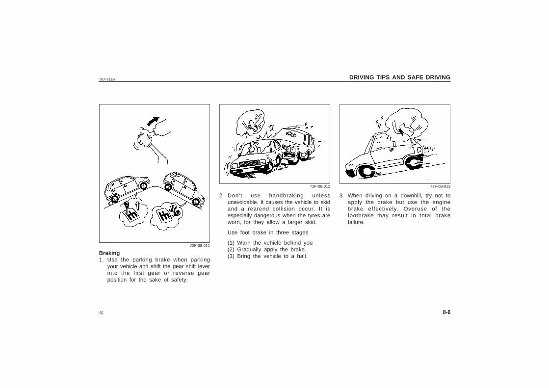
2. Don’t use handbraking unlessunavoidable. It causes the vehicle to skidand a rearend collision occur. It isespecially dangerous when the tyres areworn, for they allow a larger skid.
Use foot brake in three stages
(1) Warn the vehicle behind you(2) Gradually apply the brake.(3) Bring the vehicle to a halt.
3. When driving on a downhill, try not toapply the brake but use the enginebrake effectively. Overuse of thefootbrake may result in total brakefailure.
Braking1. Use the parking brake when parking
your vehicle and shift the gear shift leverinto the first gear or reverse gearposition for the sake of safety.
72F-08-011
72F-08-012 72F-08-013
62
797-74E-I
8-7
DRIVING TIPS AND SAFE DRIVING
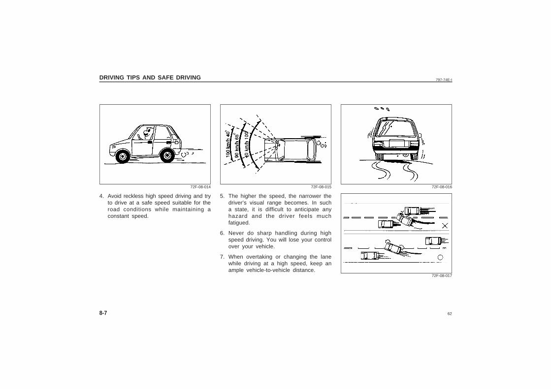
4. Avoid reckless high speed driving and tryto drive at a safe speed suitable for theroad conditions while maintaining aconstant speed.
5. The higher the speed, the narrower thedriver’s visual range becomes. In sucha state, it is difficult to anticipate anyhazard and the driver feels muchfatigued.
6. Never do sharp handling during highspeed driving. You will lose your controlover your vehicle.
7. When overtaking or changing the lanewhile driving at a high speed, keep anample vehicle-to-vehicle distance.
72F-08-014 72F-08-015 72F-08-016
72F-08-017
63
797-74E-I
8-8
DRIVING TIPS AND SAFE DRIVING
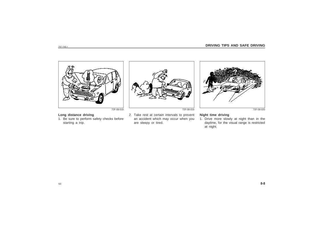
Long distance driving1. Be sure to perform safety checks before
starting a trip.
2. Take rest at certain intervals to preventan accident which may occur when youare sleepy or tired.
Night time driving1. Drive more slowly at night than in the
daytime, for the visual range is restrictedat night.
72F-08-018 72F-08-019 72F-08-020
64
797-74E-I
8-9
DRIVING TIPS AND SAFE DRIVING
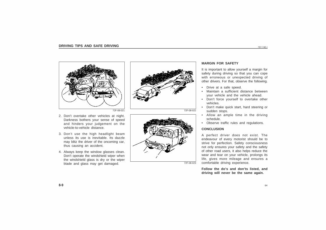
2. Don’t overtake other vehicles at night.Darkness bothers your sense of speedand hinders your judgement on thevehicle-to-vehicle distance.
3. Don’t use the high headlight beamunless its use is inevitable. Its dazzlemay blitz the driver of the oncoming car,thus causing an accident.
4. Always keep the window glasses clean.Don’t operate the windshield wiper whenthe windshield glass is dry or the wiperblade and glass may get damaged.
MARGIN FOR SAFETY
It is important to allow yourself a margin forsafety during driving so that you can copewith erroneous or unexpected driving ofother drivers. For that, observe the following.
• Drive at a safe speed.• Maintain a sufficient distance between
your vehicle and the vehicle ahead.• Don’t force yourself to overtake other
vehicles.• Don’t make quick start, hard steering or
sudden stops.• Allow an ample time in the driving
schedule.• Observe traffic rules and regulations.
CONCLUSION
A perfect driver does not exist. Theendeavour of every motorist should be tostrive for perfection. Safety consciousnessnot only ensures your safety and the safetyof other road users, it also helps reduce thewear and tear on your vehicle, prolongs itslife, gives more mileage and ensures acomfortable driving experience.
Follow the do’s and don’ts listed, anddriving will never be the same again.
72F-08-021 72F-08-022
72F-08-023
65
797-74E-I INSPECTION AND MAINTENANCE
9
INSPECTION AND MAINTENANCE
Tool Kit .................................................................................................................. 9-2Periodic Maintenance Schedule ......................................................................... 9-2Water Pump Belt .................................................................................................. 9-6Engine Oil and Filter ............................................................................................ 9-7Gear Oil ............................................................................................................... 9-10Engine Coolant ................................................................................................... 9-11Windscreen Washer Fluid ................................................................................. 9-12Air Cleaner .......................................................................................................... 9-13Spark Plugs ........................................................................................................ 9-13Brakes ................................................................................................................. 9-15Steering ............................................................................................................... 9-17Clutch Pedal ....................................................................................................... 9-17Tyres .................................................................................................................... 9-17Battery ................................................................................................................. 9-21Fuses ................................................................................................................... 9-21Bulb Replacement .............................................................................................. 9-23Wiper Blades ...................................................................................................... 9-27
66
797-74E-I
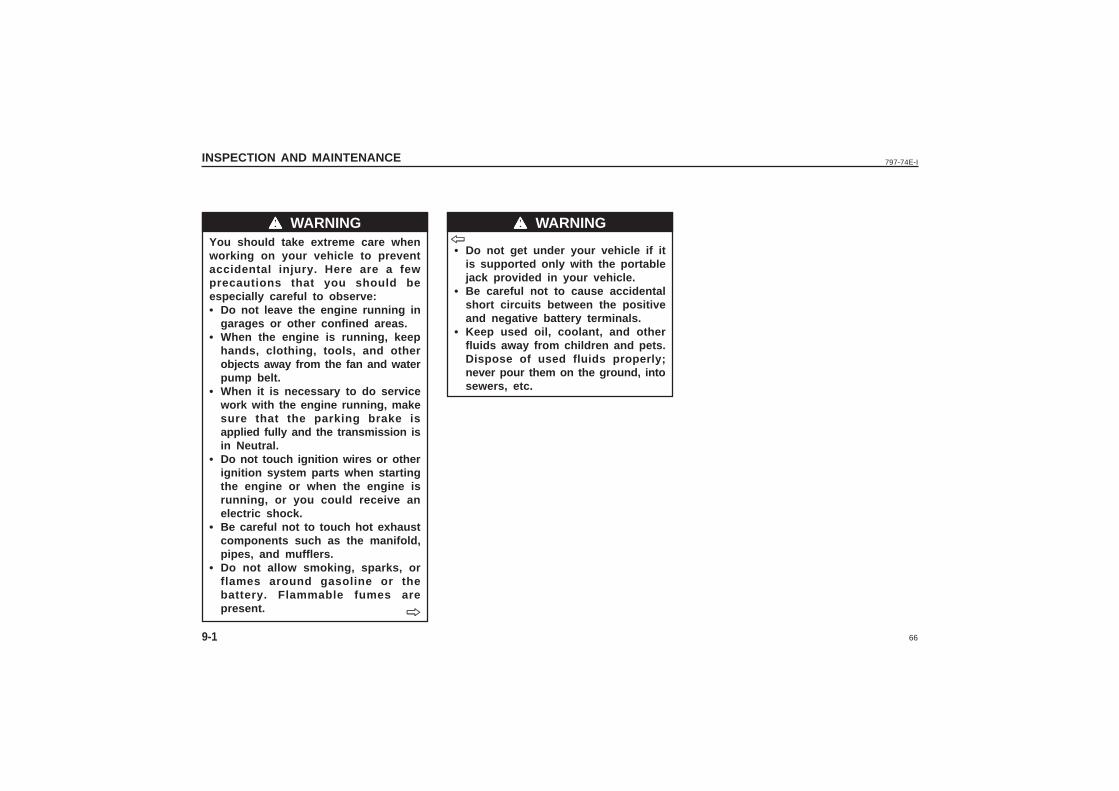
You should take extreme care whenworking on your vehicle to preventaccidental injury. Here are a fewprecautions that you should beespecially careful to observe:• Do not leave the engine running in
garages or other confined areas.• When the engine is running, keep
hands, clothing, tools, and otherobjects away from the fan and waterpump belt.
• When it is necessary to do servicework with the engine running, makesure that the parking brake isapplied fully and the transmission isin Neutral.
• Do not touch ignition wires or otherignition system parts when startingthe engine or when the engine isrunning, or you could receive anelectric shock.
• Be careful not to touch hot exhaustcomponents such as the manifold,pipes, and mufflers.
• Do not allow smoking, sparks, orflames around gasoline or thebattery. Flammable fumes arepresent.
• Do not get under your vehicle if itis supported only with the portablejack provided in your vehicle.
• Be careful not to cause accidentalshort circuits between the positiveand negative battery terminals.
• Keep used oil, coolant, and otherfluids away from children and pets.Dispose of used fluids properly;never pour them on the ground, intosewers, etc.
INSPECTION AND MAINTENANCE
9-1
wwwww WARNING wwwww WARNING
ˇ̌̌̌̌
ˇ̌̌̌̌
67
797-74E-I INSPECTION AND MAINTENANCE
9-2
TOOL KIT
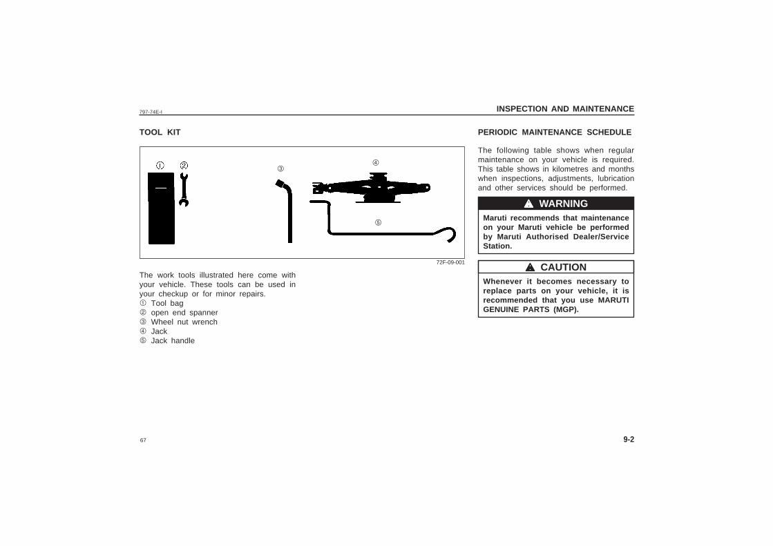
The work tools illustrated here come withyour vehicle. These tools can be used inyour checkup or for minor repairs.1 Tool bag2 open end spanner3 Wheel nut wrench4 Jack5 Jack handle
PERIODIC MAINTENANCE SCHEDULE
The following table shows when regularmaintenance on your vehicle is required.This table shows in kilometres and monthswhen inspections, adjustments, lubricationand other services should be performed.
Maruti recommends that maintenanceon your Maruti vehicle be performedby Maruti Authorised Dealer/ServiceStation.
Whenever it becomes necessary toreplace parts on your vehicle, it isrecommended that you use MARUTIGENUINE PARTS (MGP).
wwwww WARNING
wwwww CAUTION72F-09-001
34
5
68
797-74E-IINSPECTION AND MAINTENANCE
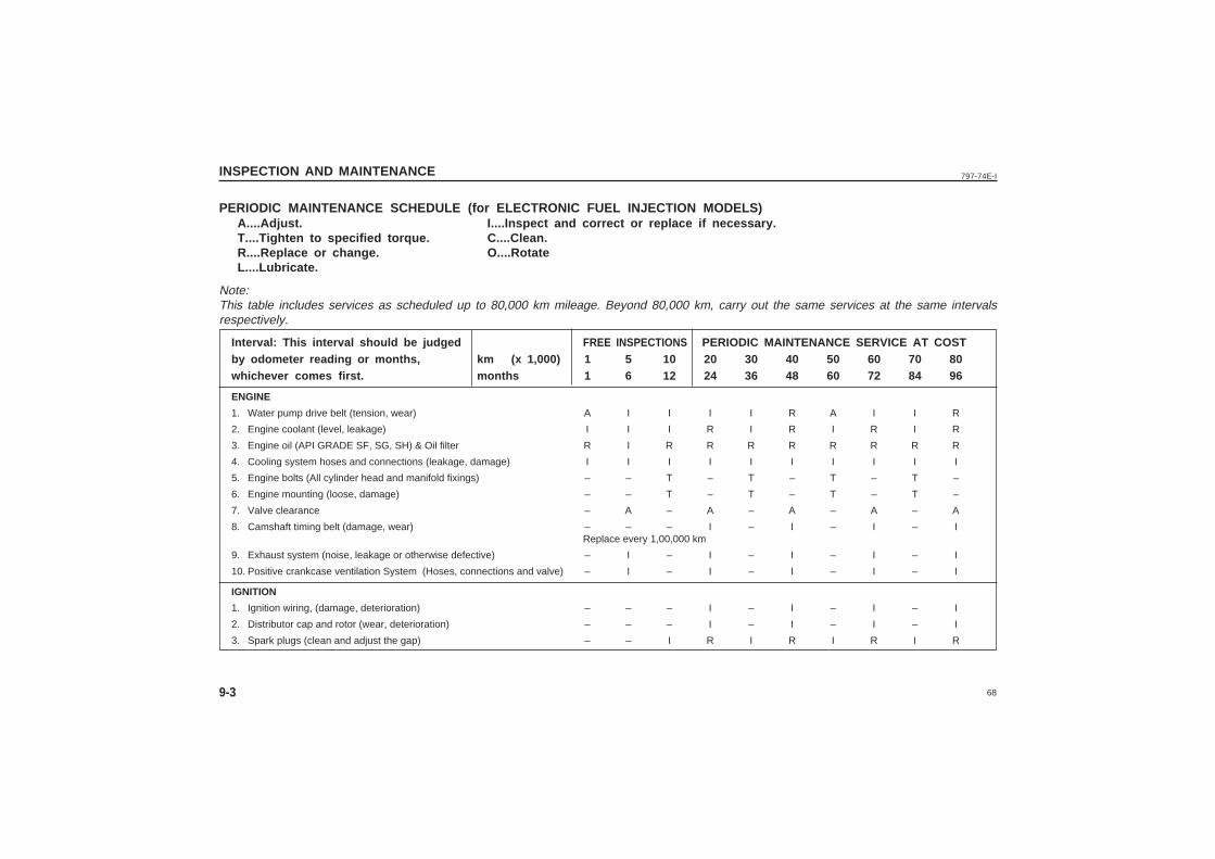
PERIODIC MAINTENANCE SCHEDULE (for ELECTRONIC FUEL INJECTION MODELS)A....Adjust. I....Inspect and correct or replace if necessary.T....Tighten to specified torque. C....Clean.R....Replace or change. O....RotateL....Lubricate.
Note:This table includes services as scheduled up to 80,000 km mileage. Beyond 80,000 km, carry out the same services at the same intervalsrespectively.
Interval: This interval should be judged FREE INSPECTIONS PERIODIC MAINTENANCE SERVICE AT COSTby odometer reading or months, km (x 1,000) 1 5 10 20 30 40 50 60 70 80whichever comes first. months 1 6 12 24 36 48 60 72 84 96
ENGINE
1. Water pump drive belt (tension, wear) A I I I I R A I I R
2. Engine coolant (level, leakage) I I I R I R I R I R
3. Engine oil (API GRADE SF, SG, SH) & Oil filter R I R R R R R R R R
4. Cooling system hoses and connections (leakage, damage) I I I I I I I I I I
5. Engine bolts (All cylinder head and manifold fixings) – – T – T – T – T –
6. Engine mounting (loose, damage) – – T – T – T – T –
7. Valve clearance – A – A – A – A – A
8. Camshaft timing belt (damage, wear) – – – I – I – I – IReplace every 1,00,000 km
9. Exhaust system (noise, leakage or otherwise defective) – I – I – I – I – I
10. Positive crankcase ventilation System (Hoses, connections and valve) – I – I – I – I – I
IGNITION
1. Ignition wiring, (damage, deterioration) – – – I – I – I – I
2. Distributor cap and rotor (wear, deterioration) – – – I – I – I – I
3. Spark plugs (clean and adjust the gap) – – I R I R I R I R
9-3
69
797-74E-I INSPECTION AND MAINTENANCE
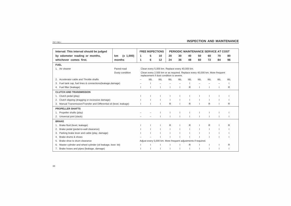
Interval: This interval should be judged FREE INSPECTIONS PERIODIC MAINTENANCE SERVICE AT COST
by odometer reading or months, km (x 1,000) 1 5 10 20 30 40 50 60 70 80whichever comes first. months 1 6 12 24 36 48 60 72 84 96
FUEL
1. Air cleaner Paved-road Clean every 5,000 km. Replace every 40,000 km.
Dusty condition Clean every 2,500 km or as required. Replace every 40,000 km. More frequentreplacement if dust condition is severe.
2. Accelerator cable and Throttle shafts – I&L I&L I&L I&L I&L I&L I&L I&L I&L
3. Fuel tank cap, fuel lines & connections(leakage,damage) – I – – – I – – – I
4. Fuel filter (leakage) I I I I I R I I I R
CLUTCH AND TRANSMISSION
1. Clutch pedal (play) I I I I I I I I I I
2. Clutch slipping (dragging or excessive damage) I I I I I I I I I I
3. Manual Transmission/Transfer and Differential oil (level, leakage) I I I R I R I R I R
PROPELLER SHAFTS
1. Propeller shafts (play) – – I I I I I I I I
2. Universal joint (slack) – – I I I I I I I I
BRAKE
1. Brake fluid (level, leakage) I I I R I R I R I R
2. Brake pedal (pedal-to-wall clearance) I I I I I I I I I I
3. Parking brake lever and cable (play, damage) I I I I I I I I I I
4. Brake drums & shoes – – I I I I I I I I
5. Brake shoe to drum clearance Adjust every 5,000 km. More frequent adjustments if required.
6. Master cylinder and wheel cylinder (oil leakage, boot kit) I I I I I R I I I R
7. Brake hoses and pipes (leakage, damage) I I I I I I I I I I
70
797-74E-IINSPECTION AND MAINTENANCE
9-5
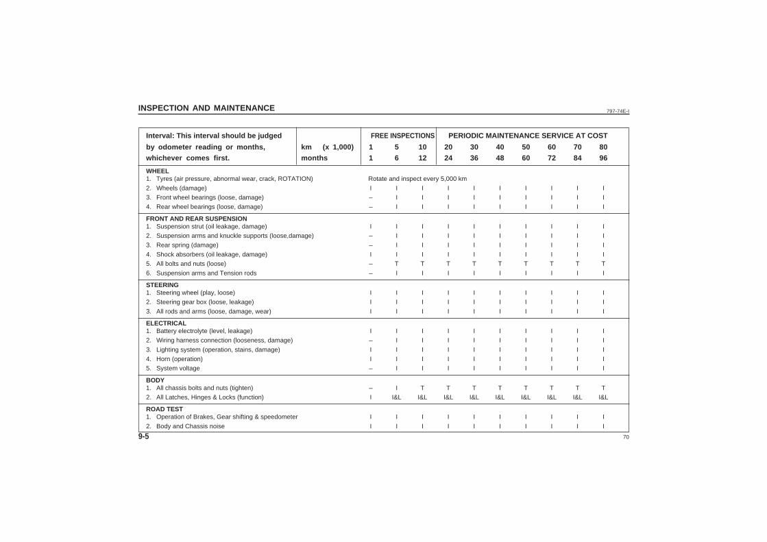
Interval: This interval should be judged FREE INSPECTIONS PERIODIC MAINTENANCE SERVICE AT COST
by odometer reading or months, km (x 1,000) 1 5 10 20 30 40 50 60 70 80
whichever comes first. months 1 6 12 24 36 48 60 72 84 96
WHEEL1. Tyres (air pressure, abnormal wear, crack, ROTATION) Rotate and inspect every 5,000 km
2. Wheels (damage) I I I I I I I I I I
3. Front wheel bearings (loose, damage) – I I I I I I I I I
4. Rear wheel bearings (loose, damage) – I I I I I I I I I
FRONT AND REAR SUSPENSION1. Suspension strut (oil leakage, damage) I I I I I I I I I I
2. Suspension arms and knuckle supports (loose,damage) – I I I I I I I I I
3. Rear spring (damage) – I I I I I I I I I
4. Shock absorbers (oil leakage, damage) I I I I I I I I I I
5. All bolts and nuts (loose) – T T T T T T T T T
6. Suspension arms and Tension rods – I I I I I I I I I
STEERING1. Steering wheel (play, loose) I I I I I I I I I I
2. Steering gear box (loose, leakage) I I I I I I I I I I
3. All rods and arms (loose, damage, wear) I I I I I I I I I I
ELECTRICAL1. Battery electrolyte (level, leakage) I I I I I I I I I I
2. Wiring harness connection (looseness, damage) – I I I I I I I I I
3. Lighting system (operation, stains, damage) I I I I I I I I I I
4. Horn (operation) I I I I I I I I I I
5. System voltage – I I I I I I I I I
BODY1. All chassis bolts and nuts (tighten) – I T T T T T T T T
2. All Latches, Hinges & Locks (function) I I&L I&L I&L I&L I&L I&L I&L I&L I&L
ROAD TEST1. Operation of Brakes, Gear shifting & speedometer I I I I I I I I I I
2. Body and Chassis noise I I I I I I I I I I
71
797-74E-I INSPECTION AND MAINTENANCE
9-6
• All maintenance should be carriedout with the ignition switch in the“OFF” position and the vehicleparked securely on the level groundunless otherwise specified.
• If you are in any way unsure of yourability to undertake a task, then donot start it but contact your Marutidealer to perform the work for you.
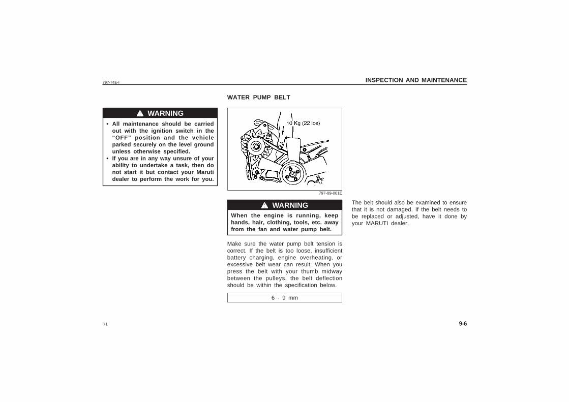
WATER PUMP BELT
The belt should also be examined to ensurethat it is not damaged. If the belt needs tobe replaced or adjusted, have it done byyour MARUTI dealer.
When the engine is running, keephands, hair, clothing, tools, etc. awayfrom the fan and water pump belt.
Make sure the water pump belt tension iscorrect. If the belt is too loose, insufficientbattery charging, engine overheating, orexcessive belt wear can result. When youpress the belt with your thumb midwaybetween the pulleys, the belt deflectionshould be within the specification below.
6 - 9 mm
wwwww WARNING
wwwww WARNING
797-09-001E
72
797-74E-IINSPECTION AND MAINTENANCE
9-7
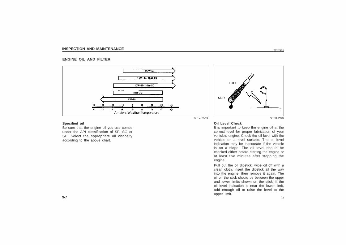
ENGINE OIL AND FILTER
Oil Level CheckIt is important to keep the engine oil at thecorrect level for proper lubrication of yourvehicle’s engine. Check the oil level with thevehicle on a level surface. The oil levelindication may be inaccurate if the vehicleis on a slope. The oil level should bechecked either before starting the engine orat least five minutes after stopping theengine.
Pull out the oil dipstick, wipe oil off with aclean cloth, insert the dipstick all the wayinto the engine, then remove it again. Theoil on the stick should be between the upperand lower limits shown on the stick. If theoil level indication is near the lower limit,add enough oil to raise the level to theupper limit.
Specified oilBe sure that the engine oil you use comesunder the API classification of SF, SG orSH. Select the appropriate oil viscosityaccording to the above chart.
70F-07-004E 797-05-003E
73
797-74E-I INSPECTION AND MAINTENANCE
9-8
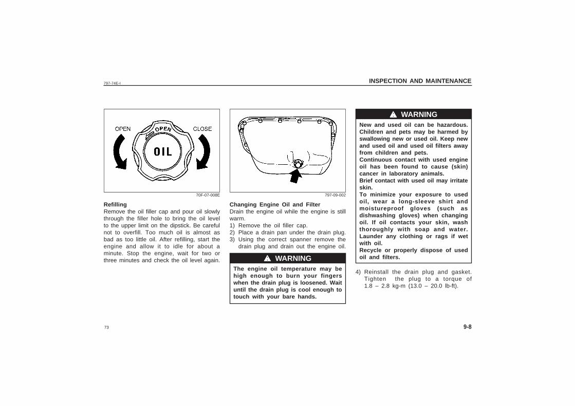
RefillingRemove the oil filler cap and pour oil slowlythrough the filler hole to bring the oil levelto the upper limit on the dipstick. Be carefulnot to overfill. Too much oil is almost asbad as too little oil. After refilling, start theengine and allow it to idle for about aminute. Stop the engine, wait for two orthree minutes and check the oil level again.
Changing Engine Oil and FilterDrain the engine oil while the engine is stillwarm.1) Remove the oil filler cap.2) Place a drain pan under the drain plug.3) Using the correct spanner remove the
drain plug and drain out the engine oil.
The engine oil temperature may behigh enough to burn your fingerswhen the drain plug is loosened. Waituntil the drain plug is cool enough totouch with your bare hands.
70F-07-008E 797-09-002
wwwww WARNING
New and used oil can be hazardous.Children and pets may be harmed byswallowing new or used oil. Keep newand used oil and used oil filters awayfrom children and pets.Continuous contact with used engineoil has been found to cause (skin)cancer in laboratory animals.Brief contact with used oil may irritateskin.To minimize your exposure to usedoil, wear a long-sleeve shirt andmoistureproof gloves (such asdishwashing gloves) when changingoil. If oil contacts your skin, washthoroughly with soap and water.Launder any clothing or rags if wetwith oil.Recycle or properly dispose of usedoil and filters.
4) Reinstall the drain plug and gasket.Tighten the plug to a torque of1.8 – 2.8 kg-m (13.0 – 20.0 lb-ft).
wwwww WARNING
74
797-74E-IINSPECTION AND MAINTENANCE
9-9
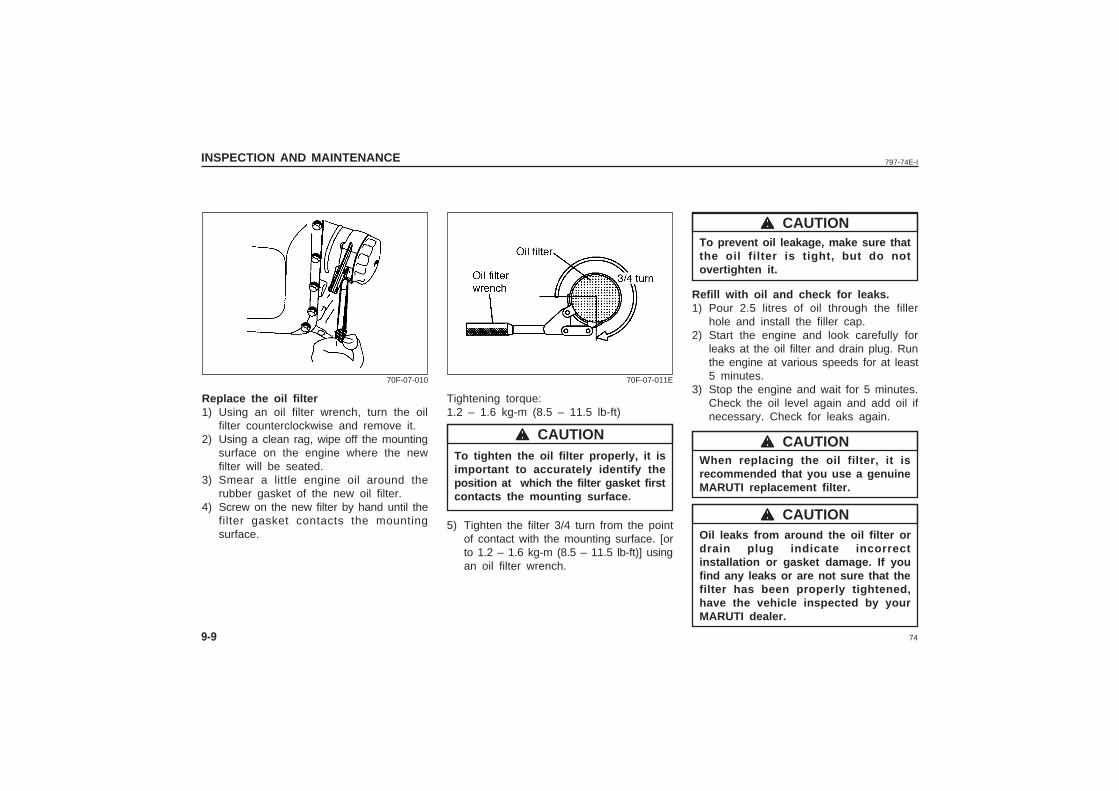
Replace the oil filter1) Using an oil filter wrench, turn the oil
filter counterclockwise and remove it.2) Using a clean rag, wipe off the mounting
surface on the engine where the newfilter will be seated.
3) Smear a little engine oil around therubber gasket of the new oil filter.
4) Screw on the new filter by hand until thefilter gasket contacts the mountingsurface.
70F-07-010
Tightening torque:1.2 – 1.6 kg-m (8.5 – 11.5 lb-ft)
To tighten the oil filter properly, it isimportant to accurately identify theposition at which the filter gasket firstcontacts the mounting surface.
5) Tighten the filter 3/4 turn from the pointof contact with the mounting surface. [orto 1.2 – 1.6 kg-m (8.5 – 11.5 lb-ft)] usingan oil filter wrench.
wwwww CAUTION
70F-07-011E
To prevent oil leakage, make sure thatthe oil filter is tight, but do notovertighten it.
Refill with oil and check for leaks.1) Pour 2.5 litres of oil through the filler
hole and install the filler cap.2) Start the engine and look carefully for
leaks at the oil filter and drain plug. Runthe engine at various speeds for at least5 minutes.
3) Stop the engine and wait for 5 minutes.Check the oil level again and add oil ifnecessary. Check for leaks again.
When replacing the oil filter, it isrecommended that you use a genuineMARUTI replacement filter.
Oil leaks from around the oil filter ordrain plug indicate incorrectinstallation or gasket damage. If youfind any leaks or are not sure that thefilter has been properly tightened,have the vehicle inspected by yourMARUTI dealer.
wwwww CAUTION
wwwww CAUTION
wwwww CAUTION
75
797-74E-I INSPECTION AND MAINTENANCE
9-10
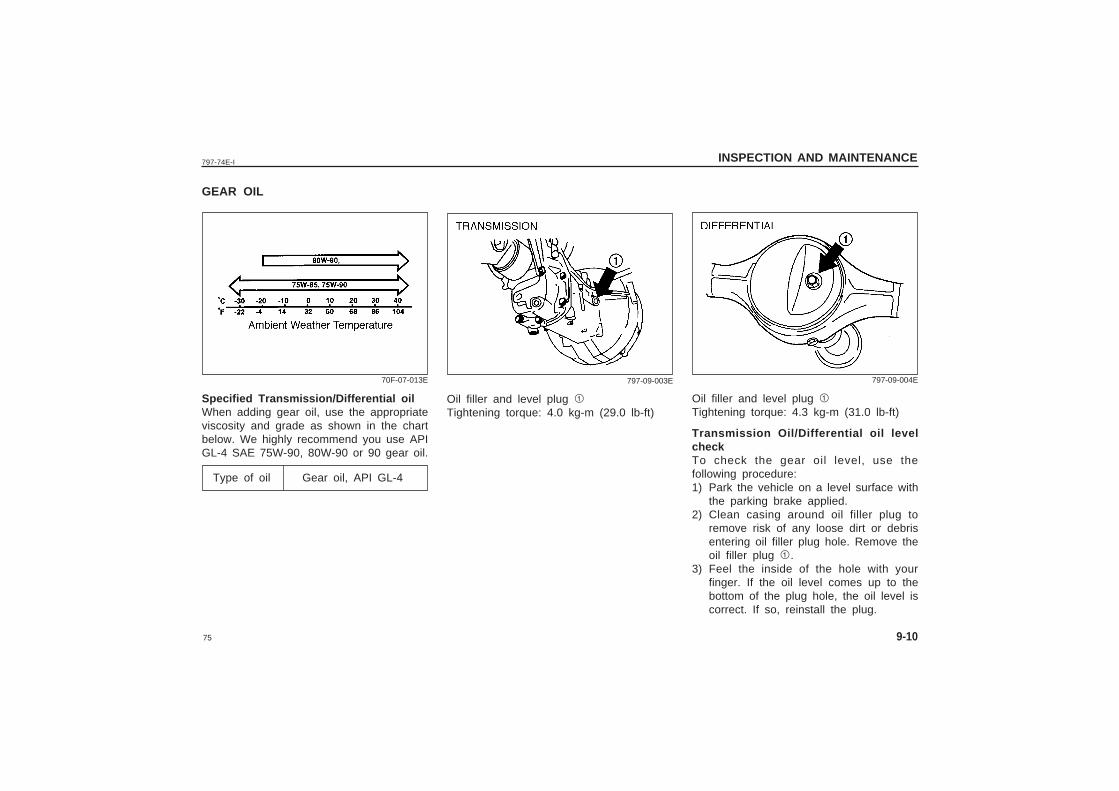
GEAR OIL
Specified Transmission/Differential oilWhen adding gear oil, use the appropriateviscosity and grade as shown in the chartbelow. We highly recommend you use APIGL-4 SAE 75W-90, 80W-90 or 90 gear oil.
Type of oil Gear oil, API GL-4
70F-07-013E
Oil filler and level plug 1Tightening torque: 4.3 kg-m (31.0 lb-ft)
Transmission Oil/Differential oil levelcheckTo check the gear oil level, use thefollowing procedure:1) Park the vehicle on a level surface with
the parking brake applied.2) Clean casing around oil filler plug to
remove risk of any loose dirt or debrisentering oil filler plug hole. Remove theoil filler plug 1.
3) Feel the inside of the hole with yourfinger. If the oil level comes up to thebottom of the plug hole, the oil level iscorrect. If so, reinstall the plug.
797-09-004E797-09-003E
Oil filler and level plug 1Tightening torque: 4.0 kg-m (29.0 lb-ft)
76
797-74E-IINSPECTION AND MAINTENANCE
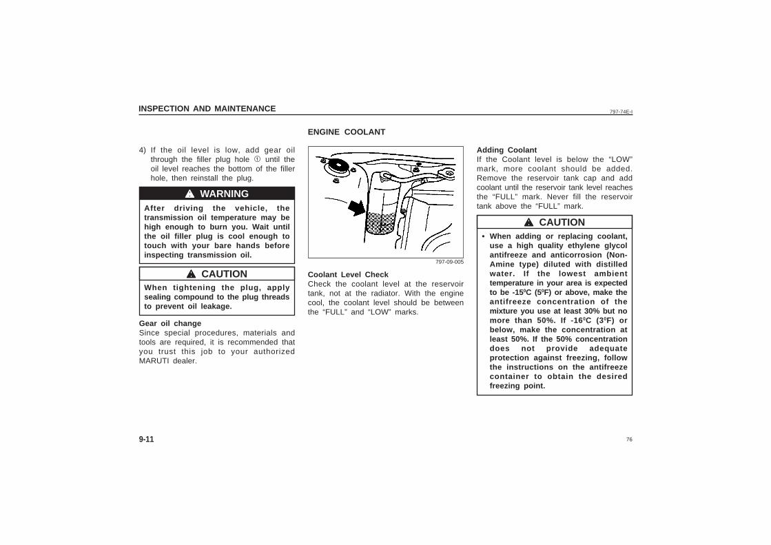
4) If the oil level is low, add gear oilthrough the filler plug hole 1 until theoil level reaches the bottom of the fillerhole, then reinstall the plug.
After driving the vehicle, thetransmission oil temperature may behigh enough to burn you. Wait untilthe oil filler plug is cool enough totouch with your bare hands beforeinspecting transmission oil.
When tightening the plug, applysealing compound to the plug threadsto prevent oil leakage.
Gear oil changeSince special procedures, materials andtools are required, it is recommended thatyou trust this job to your authorizedMARUTI dealer.
9-11
wwwww WARNING
wwwww CAUTION
Adding CoolantIf the Coolant level is below the “LOW”mark, more coolant should be added.Remove the reservoir tank cap and addcoolant until the reservoir tank level reachesthe “FULL” mark. Never fill the reservoirtank above the “FULL” mark.
• When adding or replacing coolant,use a high quality ethylene glycolantifreeze and anticorrosion (Non-Amine type) diluted with distilledwater. If the lowest ambienttemperature in your area is expectedto be -15 0C (50F) or above, make theantifreeze concentration of themixture you use at least 30% but nomore than 50%. If -16 0C (30F) orbelow, make the concentration atleast 50%. If the 50% concentrationdoes not provide adequateprotection against freezing, followthe instructions on the antifreezecontainer to obtain the desiredfreezing point.
ENGINE COOLANT
wwwww CAUTION
797-09-005
Coolant Level CheckCheck the coolant level at the reservoirtank, not at the radiator. With the enginecool, the coolant level should be betweenthe “FULL” and “LOW” marks.
77
797-74E-I INSPECTION AND MAINTENANCE
9-12
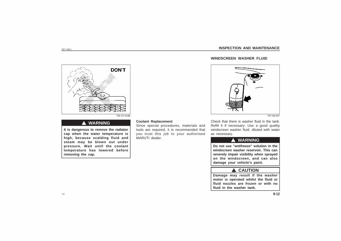
It is dangerous to remove the radiatorcap when the water temperature ishigh, because scalding fluid andsteam may be blown out underpressure. Wait until the coolanttemperature has lowered beforeremoving the cap.
70F-07-018E
wwwww WARNING
wwwww CAUTION
WINDSCREEN WASHER FLUID
Check that there is washer fluid in the tank.Refill it if necessary. Use a good qualitywindscreen washer fluid, diluted with wateras necessary.
Do not use “antifreeze” solution in thewindscreen washer reservoir. This canseverely impair visibility when sprayedon the windscreen, and can alsodamage your vehicle’s paint.
Damage may result if the washermotor is operated whilst the fluid orfluid nozzles are frozen or with nofluid in the washer tank.
wwwww WARNING
797-09-007
Coolant ReplacementSince special procedures, materials andtools are required, it is recommended thatyou trust this job to your authorisedMARUTI dealer.
78
797-74E-IINSPECTION AND MAINTENANCE
9-13
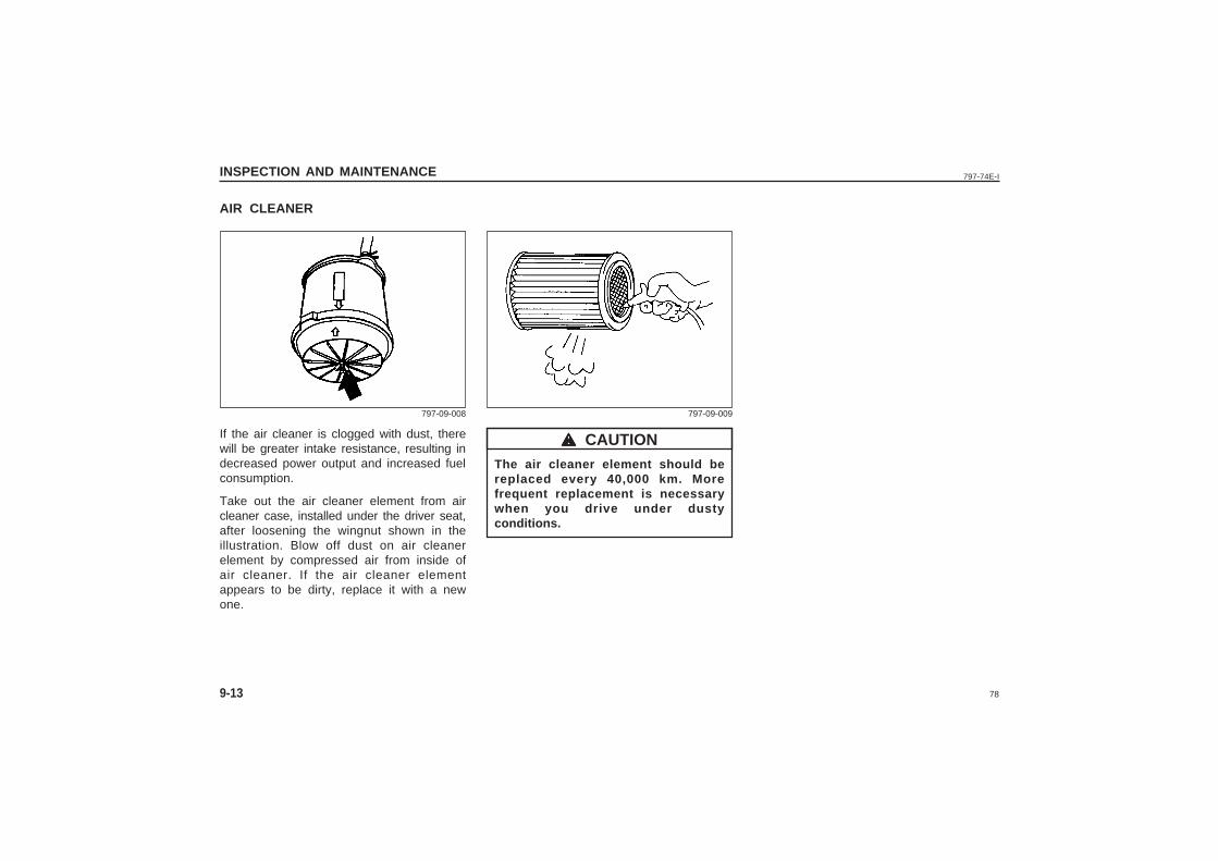
AIR CLEANER
If the air cleaner is clogged with dust, therewill be greater intake resistance, resulting indecreased power output and increased fuelconsumption.
Take out the air cleaner element from aircleaner case, installed under the driver seat,after loosening the wingnut shown in theillustration. Blow off dust on air cleanerelement by compressed air from inside ofair cleaner. If the air cleaner elementappears to be dirty, replace it with a newone.
797-09-008
The air cleaner element should bereplaced every 40,000 km. Morefrequent replacement is necessarywhen you drive under dustyconditions.
wwwww CAUTION
797-09-009
79
797-74E-I INSPECTION AND MAINTENANCE
9-14
SPARK PLUGS
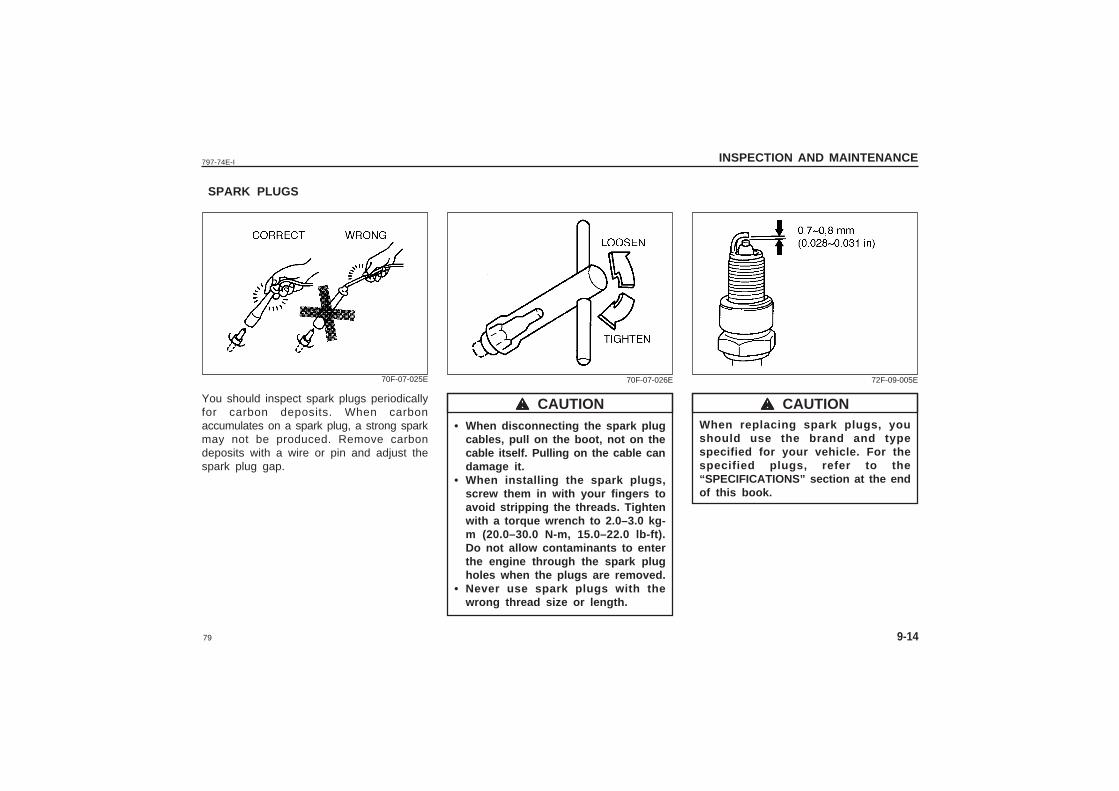
You should inspect spark plugs periodicallyfor carbon deposits. When carbonaccumulates on a spark plug, a strong sparkmay not be produced. Remove carbondeposits with a wire or pin and adjust thespark plug gap.
70F-07-025E
When replacing spark plugs, youshould use the brand and typespecified for your vehicle. For thespecified plugs, refer to the“SPECIFICATIONS” section at the endof this book.
wwwww CAUTION
72F-09-005E
• When disconnecting the spark plugcables, pull on the boot, not on thecable itself. Pulling on the cable candamage it.
• When installing the spark plugs,screw them in with your fingers toavoid stripping the threads. Tightenwith a torque wrench to 2.0–3.0 kg-m (20.0–30.0 N-m, 15.0–22.0 lb-ft).Do not allow contaminants to enterthe engine through the spark plugholes when the plugs are removed.
• Never use spark plugs with thewrong thread size or length.
wwwww CAUTION
70F-07-026E
80
797-74E-IINSPECTION AND MAINTENANCE
9-15
BRAKES
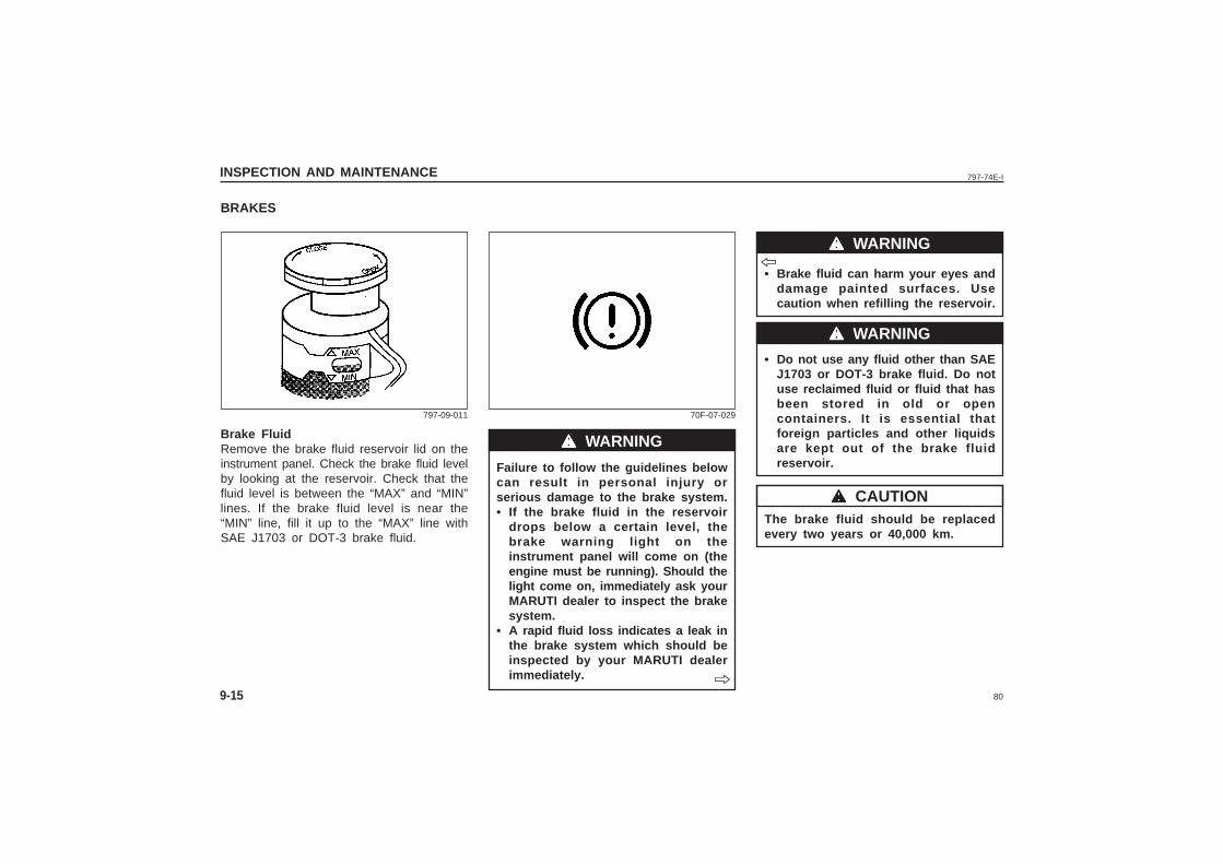
Brake FluidRemove the brake fluid reservoir lid on theinstrument panel. Check the brake fluid levelby looking at the reservoir. Check that thefluid level is between the “MAX” and “MIN”lines. If the brake fluid level is near the“MIN” line, fill it up to the “MAX” line withSAE J1703 or DOT-3 brake fluid.
797-09-011
Failure to follow the guidelines belowcan result in personal injury orserious damage to the brake system.• If the brake fluid in the reservoir
drops below a certain level, thebrake warning light on theinstrument panel will come on (theengine must be running). Should thelight come on, immediately ask yourMARUTI dealer to inspect the brakesystem.
• A rapid fluid loss indicates a leak inthe brake system which should beinspected by your MARUTI dealerimmediately.
wwwww WARNING
70F-07-029
ˇ̌̌̌̌
ˇ̌̌̌̌
• Brake fluid can harm your eyes anddamage painted surfaces. Usecaution when refilling the reservoir.
• Do not use any fluid other than SAEJ1703 or DOT-3 brake fluid. Do notuse reclaimed fluid or fluid that hasbeen stored in old or opencontainers. It is essential thatforeign particles and other liquidsare kept out of the brake fluidreservoir.
The brake fluid should be replacedevery two years or 40,000 km.
wwwww WARNING
wwwww WARNING
wwwww CAUTION
81
797-74E-I INSPECTION AND MAINTENANCE
9-16
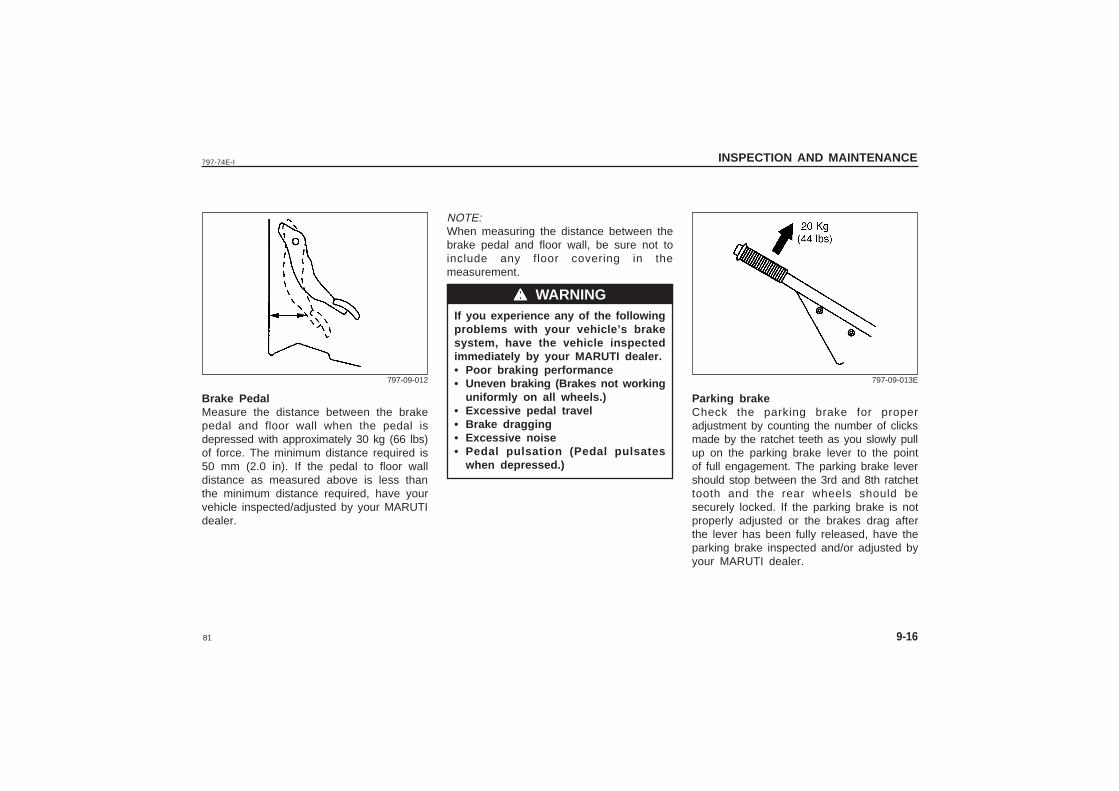
Brake PedalMeasure the distance between the brakepedal and floor wall when the pedal isdepressed with approximately 30 kg (66 lbs)of force. The minimum distance required is50 mm (2.0 in). If the pedal to floor walldistance as measured above is less thanthe minimum distance required, have yourvehicle inspected/adjusted by your MARUTIdealer.
797-09-012
Parking brakeCheck the parking brake for properadjustment by counting the number of clicksmade by the ratchet teeth as you slowly pullup on the parking brake lever to the pointof full engagement. The parking brake levershould stop between the 3rd and 8th ratchettooth and the rear wheels should besecurely locked. If the parking brake is notproperly adjusted or the brakes drag afterthe lever has been fully released, have theparking brake inspected and/or adjusted byyour MARUTI dealer.
797-09-013E
NOTE:When measuring the distance between thebrake pedal and floor wall, be sure not toinclude any floor covering in themeasurement.
If you experience any of the followingproblems with your vehicle’s brakesystem, have the vehicle inspectedimmediately by your MARUTI dealer.• Poor braking performance• Uneven braking (Brakes not working
uniformly on all wheels.)• Excessive pedal travel• Brake dragging• Excessive noise• Pedal pulsation (Pedal pulsates
when depressed.)
wwwww WARNING
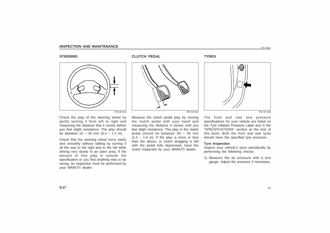
82
797-74E-IINSPECTION AND MAINTENANCE
9-17
STEERING
Check the play of the steering wheel bygently turning it from left to right andmeasuring the distance that it moves beforeyou feel slight resistance. The play shouldbe between 10 – 30 mm (0.4 – 1.2 in).
Check that the steering wheel turns easilyand smoothly without rattling by turning itall the way to the right and to the left whiledriving very slowly in an open area. If theamount of free play is outside thespecification or you find anything else to bewrong, an inspection must be performed byyour MARUTI dealer.
797-09-015
TYRES
The front and rear tyre pressurespecifications for your vehicle are listed onthe Tyre Inflation Pressure Label and in the“SPECIFICATIONS” section at the end ofthis book. Both the front and rear tyresshould have the specified tyre pressure.
Tyre InspectionInspect your vehicle’s tyres periodically byperforming the following checks:
1) Measure the air pressure with a tyregauge. Adjust the pressure if necessary.
70F-07-035
CLUTCH PEDAL
Measure the clutch pedal play by movingthe clutch pedal with your hand andmeasuring the distance it moves until youfeel slight resistance. The play in the clutchpedal should be between 30 – 35 mm(1.2 – 1.4 in). If the play is more or lessthan the above, or clutch dragging is feltwith the pedal fully depressed, have theclutch inspected by your MARUTI dealer.
70F-07-034
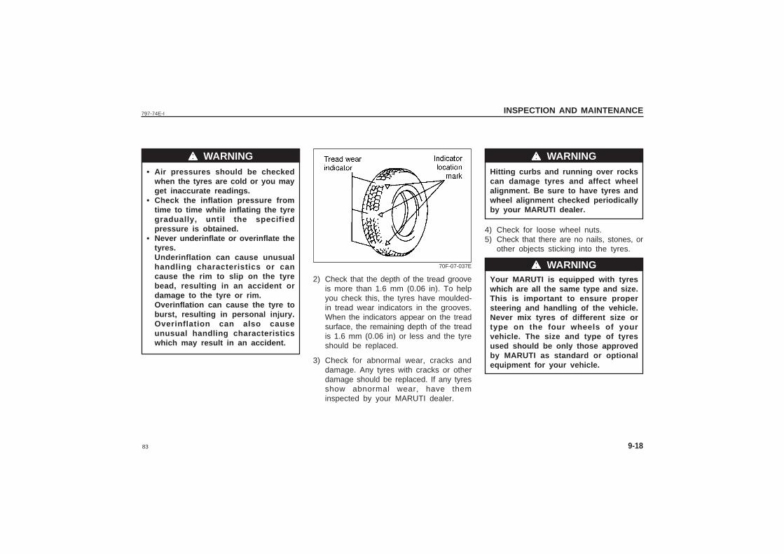
83
797-74E-I INSPECTION AND MAINTENANCE
9-18
• Air pressures should be checkedwhen the tyres are cold or you mayget inaccurate readings.
• Check the inflation pressure fromtime to time while inflating the tyregradually, until the specifiedpressure is obtained.
• Never underinflate or overinflate thetyres.Underinflation can cause unusualhandling characteristics or cancause the rim to slip on the tyrebead, resulting in an accident ordamage to the tyre or rim.Overinflation can cause the tyre toburst, resulting in personal injury.Overinflation can also causeunusual handling characteristicswhich may result in an accident.
wwwww WARNINGHitting curbs and running over rockscan damage tyres and affect wheelalignment. Be sure to have tyres andwheel alignment checked periodicallyby your MARUTI dealer.
4) Check for loose wheel nuts.5) Check that there are no nails, stones, or
other objects sticking into the tyres.
Your MARUTI is equipped with tyreswhich are all the same type and size.This is important to ensure propersteering and handling of the vehicle.Never mix tyres of different size ortype on the four wheels of yourvehicle. The size and type of tyresused should be only those approvedby MARUTI as standard or optionalequipment for your vehicle.
wwwww WARNING
wwwww WARNING2) Check that the depth of the tread groove
is more than 1.6 mm (0.06 in). To helpyou check this, the tyres have moulded-in tread wear indicators in the grooves.When the indicators appear on the treadsurface, the remaining depth of the treadis 1.6 mm (0.06 in) or less and the tyreshould be replaced.
3) Check for abnormal wear, cracks anddamage. Any tyres with cracks or otherdamage should be replaced. If any tyresshow abnormal wear, have theminspected by your MARUTI dealer.
70F-07-037E
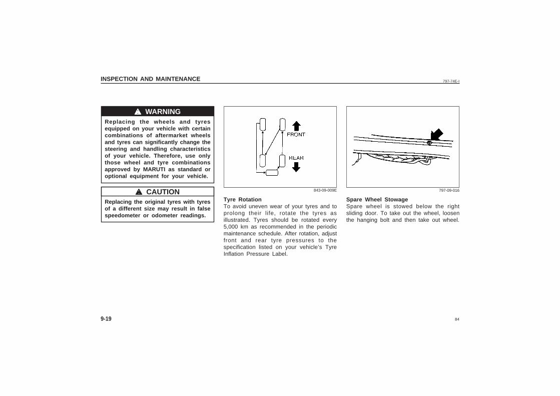
84
797-74E-IINSPECTION AND MAINTENANCE
9-19
Replacing the wheels and tyresequipped on your vehicle with certaincombinations of aftermarket wheelsand tyres can significantly change thesteering and handling characteristicsof your vehicle. Therefore, use onlythose wheel and tyre combinationsapproved by MARUTI as standard oroptional equipment for your vehicle.
Replacing the original tyres with tyresof a different size may result in falsespeedometer or odometer readings.
wwwww WARNING
wwwww CAUTIONTyre RotationTo avoid uneven wear of your tyres and toprolong their life, rotate the tyres asillustrated. Tyres should be rotated every5,000 km as recommended in the periodicmaintenance schedule. After rotation, adjustfront and rear tyre pressures to thespecification listed on your vehicle’s TyreInflation Pressure Label.
843-09-009E
Spare Wheel StowageSpare wheel is stowed below the rightsliding door. To take out the wheel, loosenthe hanging bolt and then take out wheel.
797-09-016
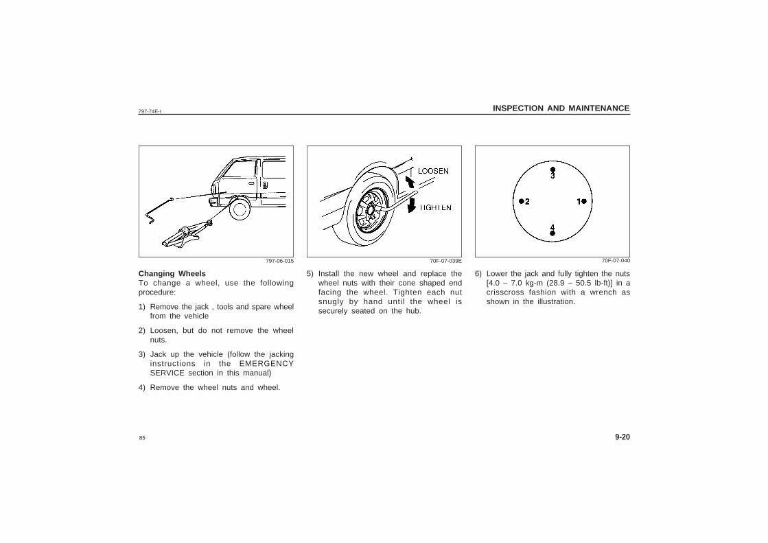
85
797-74E-I INSPECTION AND MAINTENANCE
9-20
Changing WheelsTo change a wheel, use the followingprocedure:
1) Remove the jack , tools and spare wheelfrom the vehicle
2) Loosen, but do not remove the wheelnuts.
3) Jack up the vehicle (follow the jackinginstructions in the EMERGENCYSERVICE section in this manual)
4) Remove the wheel nuts and wheel.
797-06-015
5) Install the new wheel and replace thewheel nuts with their cone shaped endfacing the wheel. Tighten each nutsnugly by hand until the wheel issecurely seated on the hub.
70F-07-039E 70F-07-040
6) Lower the jack and fully tighten the nuts[4.0 – 7.0 kg-m (28.9 – 50.5 lb-ft)] in acrisscross fashion with a wrench asshown in the illustration.
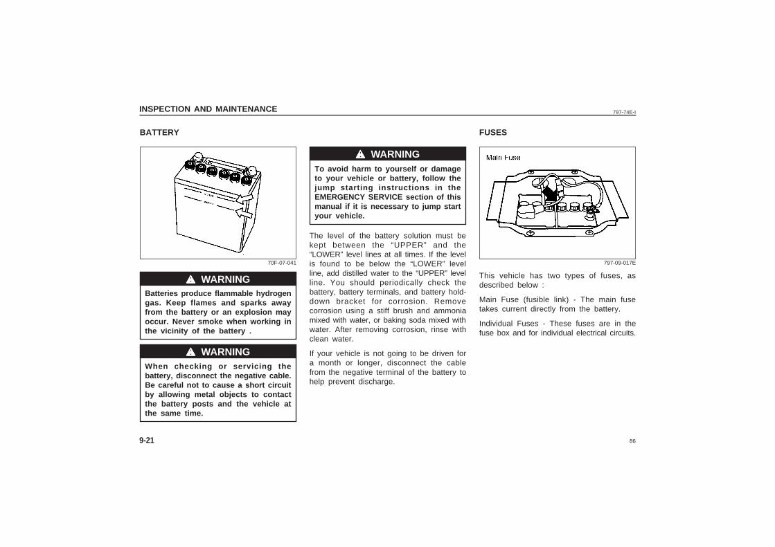
86
797-74E-IINSPECTION AND MAINTENANCE
9-21
BATTERY
Batteries produce flammable hydrogengas. Keep flames and sparks awayfrom the battery or an explosion mayoccur. Never smoke when working inthe vicinity of the battery .
When checking or servicing thebattery, disconnect the negative cable.Be careful not to cause a short circuitby allowing metal objects to contactthe battery posts and the vehicle atthe same time.
wwwww WARNING
wwwww WARNING
70F-07-041
To avoid harm to yourself or damageto your vehicle or battery, follow thejump starting instructions in theEMERGENCY SERVICE section of thismanual if it is necessary to jump startyour vehicle.
The level of the battery solution must bekept between the “UPPER” and the“LOWER” level lines at all times. If the levelis found to be below the “LOWER” levelline, add distilled water to the “UPPER” levelline. You should periodically check thebattery, battery terminals, and battery hold-down bracket for corrosion. Removecorrosion using a stiff brush and ammoniamixed with water, or baking soda mixed withwater. After removing corrosion, rinse withclean water.
If your vehicle is not going to be driven fora month or longer, disconnect the cablefrom the negative terminal of the battery tohelp prevent discharge.
FUSES
This vehicle has two types of fuses, asdescribed below :
Main Fuse (fusible link) - The main fusetakes current directly from the battery.
Individual Fuses - These fuses are in thefuse box and for individual electrical circuits.
wwwww WARNING
797-09-017E
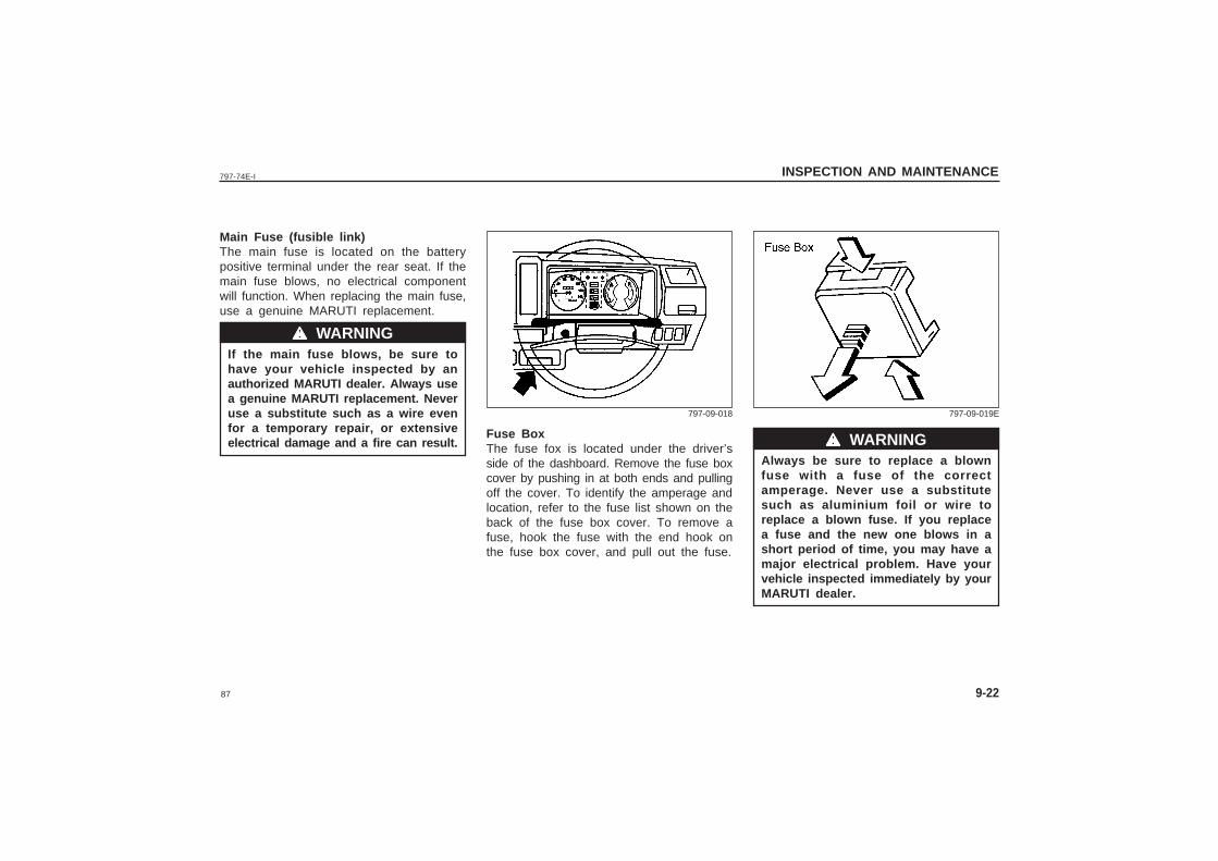
87
797-74E-I INSPECTION AND MAINTENANCE
9-22
Main Fuse (fusible link)The main fuse is located on the batterypositive terminal under the rear seat. If themain fuse blows, no electrical componentwill function. When replacing the main fuse,use a genuine MARUTI replacement.
If the main fuse blows, be sure tohave your vehicle inspected by anauthorized MARUTI dealer. Always usea genuine MARUTI replacement. Neveruse a substitute such as a wire evenfor a temporary repair, or extensiveelectrical damage and a fire can result.
wwwww WARNING
Fuse BoxThe fuse fox is located under the driver’sside of the dashboard. Remove the fuse boxcover by pushing in at both ends and pullingoff the cover. To identify the amperage andlocation, refer to the fuse list shown on theback of the fuse box cover. To remove afuse, hook the fuse with the end hook onthe fuse box cover, and pull out the fuse.
Always be sure to replace a blownfuse with a fuse of the correctamperage. Never use a substitutesuch as aluminium foil or wire toreplace a blown fuse. If you replacea fuse and the new one blows in ashort period of time, you may have amajor electrical problem. Have yourvehicle inspected immediately by yourMARUTI dealer.
wwwww WARNING
797-09-018 797-09-019E
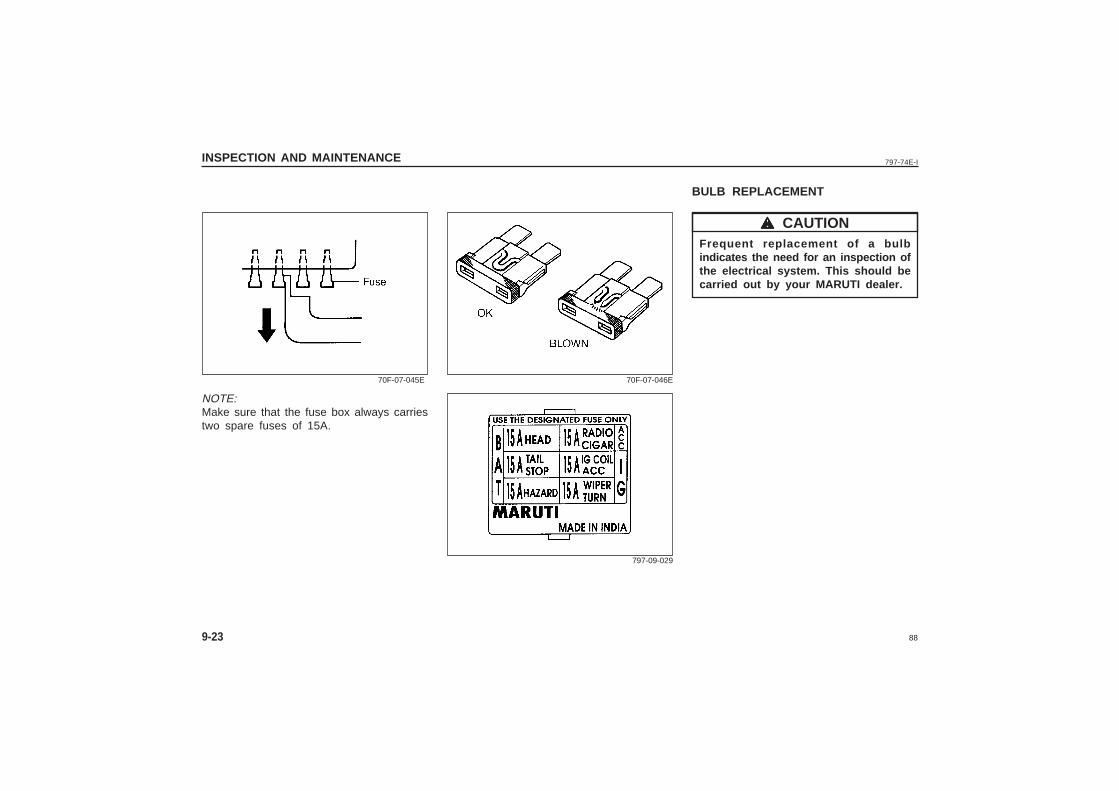
88
797-74E-IINSPECTION AND MAINTENANCE
9-23
NOTE:Make sure that the fuse box always carriestwo spare fuses of 15A.
70F-07-045E 70F-07-046E
797-09-029
BULB REPLACEMENT
Frequent replacement of a bulbindicates the need for an inspection ofthe electrical system. This should becarried out by your MARUTI dealer.
wwwww CAUTION
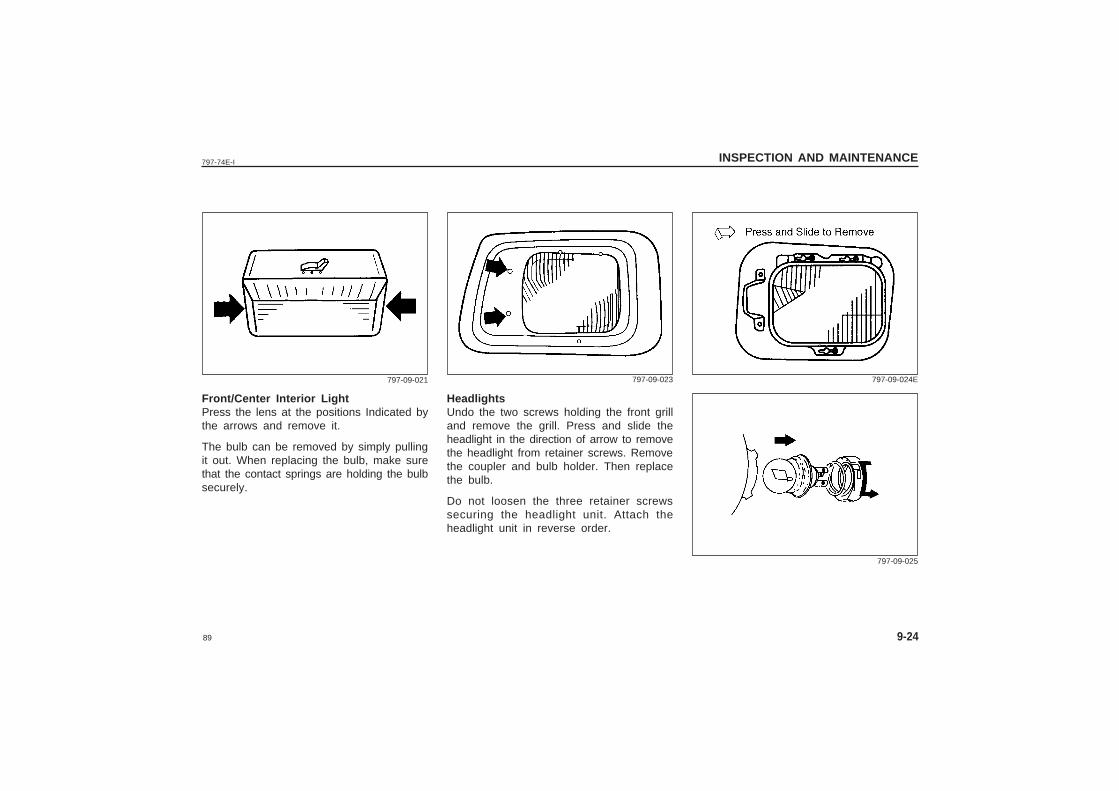
89
797-74E-I INSPECTION AND MAINTENANCE
9-24
Front/Center Interior LightPress the lens at the positions Indicated bythe arrows and remove it.
The bulb can be removed by simply pullingit out. When replacing the bulb, make surethat the contact springs are holding the bulbsecurely.
797-09-021
HeadlightsUndo the two screws holding the front grilland remove the grill. Press and slide theheadlight in the direction of arrow to removethe headlight from retainer screws. Removethe coupler and bulb holder. Then replacethe bulb.
Do not loosen the three retainer screwssecuring the headlight unit. Attach theheadlight unit in reverse order.
797-09-023 797-09-024E
797-09-025
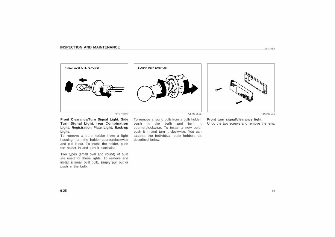
90
797-74E-IINSPECTION AND MAINTENANCE
9-25
Front Clearance/Turn Signal Light, SideTurn Signal Light, rear CombinationLight, Registration Plate Light, Back-upLight.To remove a bulb holder from a lighthousing, turn the holder counterclockwiseand pull it out. To install the holder, pushthe holder in and turn it clockwise.
Two types (small oval and round) of bulbare used for these lights. To remove andinstall a small oval bulb, simply pull out orpush in the bulb.
70F-07-050E
Front turn signal/clearance lightUndo the two screws and remove the lens.
843-09-016
To remove a round bulb from a bulb holder,push in the bulb and turn itcounterclockwise. To install a new bulb,push it in and turn it clockwise. You canaccess the individual bulb holders asdescribed below:
70F-07-051E
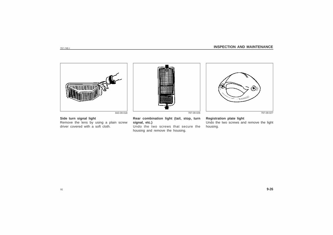
91
797-74E-I INSPECTION AND MAINTENANCE
9-26
Side turn signal lightRemove the lens by using a plain screwdriver covered with a soft cloth.
843-09-018
Rear combination light (tail, stop, turnsignal, etc.)Undo the two screws that secure thehousing and remove the housing.
797-09-026
Registration plate lightUndo the two screws and remove the lighthousing.
797-09-027
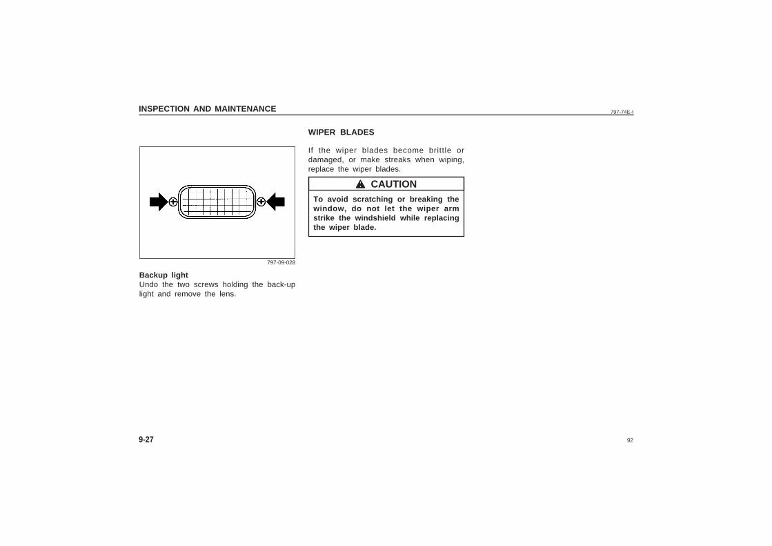
92
797-74E-IINSPECTION AND MAINTENANCE
9-27
Backup lightUndo the two screws holding the back-uplight and remove the lens.
797-09-028
WIPER BLADES
If the wiper blades become brittle ordamaged, or make streaks when wiping,replace the wiper blades.
To avoid scratching or breaking thewindow, do not let the wiper armstrike the windshield while replacingthe wiper blade.
wwwww CAUTION
93
797-74E-I EMERGENCY SERVICE
10
EMERGENCY SERVICE
Jacking Instructions ......................................................................................... 10-1
Jump Starting Instructions ............................................................................. 10-2
Towing ................................................................................................................10-3
Emergency Remedies ......................................................................................10-4
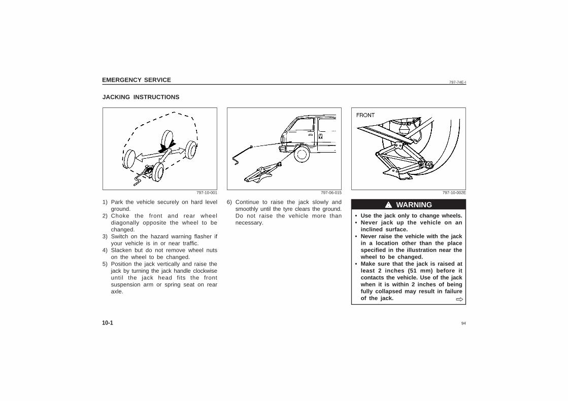
94
797-74E-IEMERGENCY SERVICE
10-1
JACKING INSTRUCTIONS
6) Continue to raise the jack slowly andsmoothly until the tyre clears the ground.Do not raise the vehicle more thannecessary.
• Use the jack only to change wheels.• Never jack up the vehicle on an
inclined surface.• Never raise the vehicle with the jack
in a location other than the placespecified in the illustration near thewheel to be changed.
• Make sure that the jack is raised atleast 2 inches (51 mm) before itcontacts the vehicle. Use of the jackwhen it is within 2 inches of beingfully collapsed may result in failureof the jack.
1) Park the vehicle securely on hard levelground.
2) Choke the front and rear wheeldiagonally opposite the wheel to bechanged.
3) Switch on the hazard warning flasher ifyour vehicle is in or near traffic.
4) Slacken but do not remove wheel nutson the wheel to be changed.
5) Position the jack vertically and raise thejack by turning the jack handle clockwiseuntil the jack head fits the frontsuspension arm or spring seat on rearaxle.
wwwww WARNING
797-10-001 797-06-015 797-10-002E
ˇ̌̌̌̌
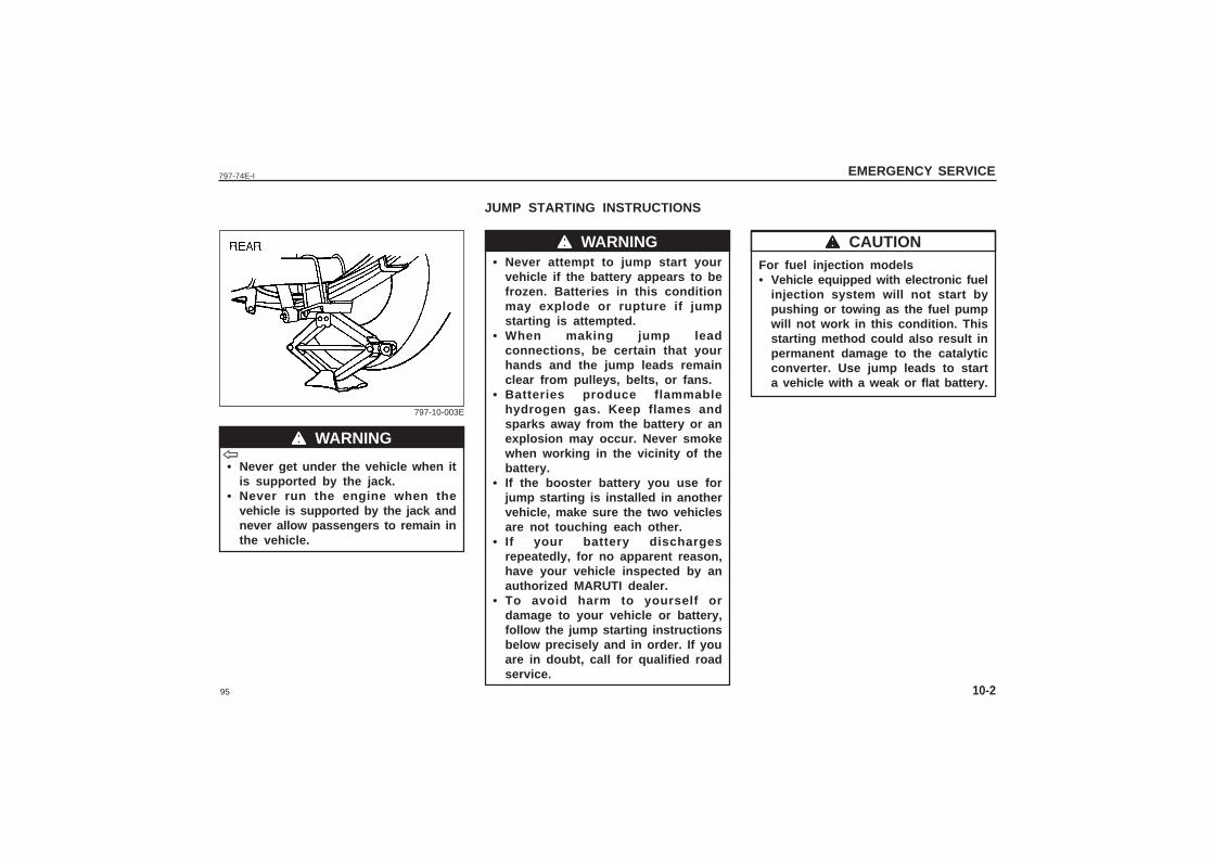
95
797-74E-I EMERGENCY SERVICE
10-2
• Never get under the vehicle when itis supported by the jack.
• Never run the engine when thevehicle is supported by the jack andnever allow passengers to remain inthe vehicle.
JUMP STARTING INSTRUCTIONS
• Never attempt to jump start yourvehicle if the battery appears to befrozen. Batteries in this conditionmay explode or rupture if jumpstarting is attempted.
• When making jump leadconnections, be certain that yourhands and the jump leads remainclear from pulleys, belts, or fans.
• Batteries produce flammablehydrogen gas. Keep flames andsparks away from the battery or anexplosion may occur. Never smokewhen working in the vicinity of thebattery.
• If the booster battery you use forjump starting is installed in anothervehicle, make sure the two vehiclesare not touching each other.
• If your battery dischargesrepeatedly, for no apparent reason,have your vehicle inspected by anauthorized MARUTI dealer.
• To avoid harm to yourself ordamage to your vehicle or battery,follow the jump starting instructionsbelow precisely and in order. If youare in doubt, call for qualified roadservice.
wwwww WARNING
wwwww WARNING
797-10-003E
For fuel injection models• Vehicle equipped with electronic fuel
injection system will not start bypushing or towing as the fuel pumpwill not work in this condition. Thisstarting method could also result inpermanent damage to the catalyticconverter. Use jump leads to starta vehicle with a weak or flat battery.
ˇ̌̌̌̌wwwww CAUTION
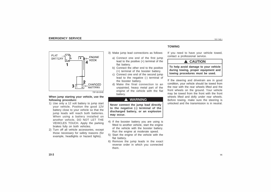
96
797-74E-IEMERGENCY SERVICE
10-3
wwwww WARNING
70F-08-004E
wwwww CAUTION
When jump starting your vehicle, use thefollowing procedure:1) Use only a 12 volt battery to jump start
your vehicle. Position the good 12Vbattery close to your vehicle so that thejump leads will reach both batteries.When using a battery installed onanother vehicle, DO NOT LET THEVEHICLES TOUCH. Apply the parkingbrakes fully on both vehicles.
2) Turn off all vehicle accessories, exceptthose necessary for safety reasons (forexample, headlights or hazard lights).
3) Make jump lead connections as follows:
a) Connect one end of the first jumplead to the positive (+) terminal of theflat battery.
b) Connect the other end to the positive(+) terminal of the booster battery.
c) Connect one end of the second jumplead to the negative (-) terminal ofthe booster battery.
d) Make the final connection to anunpainted, heavy metal part of theengine of the vehicle with the flatbattery.
Never connect the jump lead directlyto the negative (-) terminal of thedischarged battery, or an explosionmay occur.
4) If the booster battery you are using isfitted to another vehicle, start the engineof the vehicle with the booster battery.Run the engine at moderate speed.
5) Start the engine of the vehicle with theflat battery.
6) Remove the jump leads in the exactreverse order in which you connectedthem.
TOWING
If you need to have your vehicle towed,contact a professional service.
To help avoid damage to your vehicleduring towing, proper equipment andtowing procedures must be used.
If the steering and drivetrain are in goodcondition, your vehicle should be towed fromthe rear with the rear wheels lifted and thefront wheels on the ground. Your vehiclemay be towed from the front with the frontwheels lifted and dolly under rear wheels.Before towing, make sure the steering isunlocked and the transmission is in neutral.
97
797-74E-I EMERGENCY SERVICE
10-4
EMERGENCY REMEDIES
If the Engine OverheatsThe engine could overheat temporarily undersevere driving conditions. If the enginecoolant temperature gauge indicatesoverheating during driving:
1) Turn off the air conditioner, if equipped.
2) Take the vehicle to a safe place andpark.
3) Let the engine run at normal idle speedfor a few minutes until the indicator iswithin the normal, acceptabletemperature range between “H” and “C”.
If you see or hear escaping steam,stop the vehicle in a safe place andimmediately turn off the engine to letit cool. Do not remove the seats whensteam is present. When the steam canno longer be seen or heard, removethe seats to see if the coolant is tillboiling. If it is, you must wait until itstops boiling before you proceed.
If the Starter Does Not Operate:1) Try turning the ignition switch to the
“START” position with the headlightsturned on to determine the batterycondition. If the headlights go excessivelydim or go off, it usually means thateither the battery is flat or the batteryterminal contact is poor. Recharge thebattery or correct battery terminal contactas necessary.
2) If the headlights remain bright, check thefuses. If the reason for failure of thestarter is not obvious, there may be amajor electrical problem. Have thevehicle inspected by your authorizedMARUTI dealer.
If the Engine is FloodedIf the engine is flooded with petrol, it maybe hard to start. If this happens, press theaccelerator pedal all the way to the floorand hold it there while cranking the engine.(Do not operate the starter motor for morethan 15 seconds). Release the acceleratoras soon as the engine has started.
wwwww WARNING
If the temperature indication does not comedown to within the normal, acceptablerange:
1) Turn off the engine and check that thewater pump belt and pulleys are notdamaged or slipping. If any abnormalityis found, correct it.
2) Check the coolant level in the reservoir.If it is found to be lower than the “LOW”line, look for leaks at the radiator, waterpump, and radiator hoses. If you locateany leaks that may have caused theoverheating, do not run the engine untilthese problems have been corrected.
3) If you do not find a leak, carefully addcoolant to the reservoir and then theradiator, if necessary. (Refer to “ENGINECOOLANT” in the “INSPECTION ANDMAINTENANCE” section.)
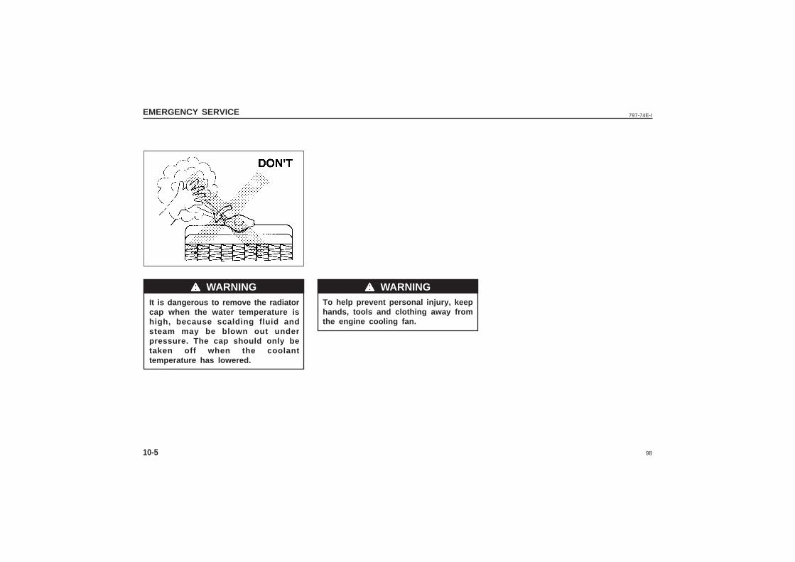
98
797-74E-IEMERGENCY SERVICE
10-5
It is dangerous to remove the radiatorcap when the water temperature ishigh, because scalding fluid andsteam may be blown out underpressure. The cap should only betaken off when the coolanttemperature has lowered.
wwwww WARNING wwwww WARNINGTo help prevent personal injury, keephands, tools and clothing away fromthe engine cooling fan.
99
797-74E-I BODY WORK CARE
11
BODY WORK CARE
Corrosion Prevention .......................................................................................11-1
Vehicle Cleaning ...............................................................................................11-2
100
797-74E-IBODY WORK CARE
11-1
CORROSION PREVENTION
the vehicle which are not well ventilatedto permit quick drying.
This information illustrates the necessity ofkeeping your vehicle (particularly theunderbody) as clean and dry as possible.It is equally important to repair any damageto the paint or protective coatings as soonas possible.
How to Help Prevent Corrosion
Wash your vehicle frequentlyThe best way to preserve the finish on yourvehicle and to help avoid corrosion is tokeep it clean with frequent washing.Wash your vehicle regularly during thewinter and immediately after the winter.Keep your vehicle, particularly the underside,as clean and dry as possible.If you frequently drive on salted roads, yourvehicle should be washed at least once amonth during the winter. If you live near theocean, your vehicle should be washed atleast once a month throughout the year.For washing instructions, refer to the“VEHICLE CLEANING” section.
Remove foreign material depositsForeign material such as salts, chemicals,road oil or tar, tree sap, bird droppings andindustrial fall-out may damage the finish ofyour vehicle if it is left on painted surfaces.
Remove these types of deposits as quicklyas possible. If these deposits are difficult towash off, an additional cleaner may berequired. Be sure that any cleaner you useis not harmful to painted surfaces and isspecifically intended for your purposes.Follow the manufacturer’s directions whenusing these special cleaners.
Repair finish damageCarefully examine your vehicle for damageto the painted surfaces. Should you find anychips or scratches in the paint, touch themup immediately to prevent corrosion fromstarting. If the chips or scratches have gonethrough to the bare metal, have a qualifiedbody shop make the repair.
Keep Passenger and luggagecompartments clean.Moisture, dirt or mud can accumulate underthe floor mats and may cause corrosion.Occasionally, check under these mats toensure that this area is clean and dry. Morefrequent checks are necessary if the vehicleis used off road or in wet weather.
Certain cargos such as chemicals, fertilizers,cleaners, salts, etc., are extremely corrosiveby nature. These products should betransported in sealed containers. If a spillor leak does occur, clean and dry the areaimmediately.
It is important to take good care of yourvehicle to protect it from corrosion.Listed below are instructions for how tomaintain your vehicle to prevent corrosion.Please read and follow these instructionscarefully.
Important Information About Corrosion
Common causes of corrosion1) Accumulation of road salt, dirt, moisture,
or chemicals in hard to reach areas ofthe vehicle underbody or frame.
2) Chipping, scratches and any damage totreated or painted metal surfacesresulting from minor accidents orabrasion by stones and gravel.
Environmental conditions whichaccelerate corrosion1) Road salt, dust control chemicals, sea air
or industrial pollution will all acceleratethe corrosion of metal.
2) High humidity will increase the rate ofcorrosion particularly when thetemperature range is just above thefreezing point.
3) Moisture in certain areas of a vehicle foran extended period of time may promotecorrosion even though other bodysections may be completely dry.
4) High temperatures will cause anaccelerated rate of corrosion to parts of
101
797-74E-I BODY WORK CARE
11-2
Store your vehicle in a dry, well-ventilated area.Do not park your vehicle in a damp, poorlyventilated area. If you often wash yourvehicle in the garage or if you frequentlydrive it in when wet, your garage may bedamp. The high humidity in the garage maycause or accelerate corrosion. A wet vehiclemay corrode even in a heated garage if theventilation is poor.
Do not apply additional undercoatingor rust preventive coating on oraround exhaust system componentssuch as the exhaust pipes, etc. A firecould be started if the undercoatingsubstance becomes overheated.
Cover your vehicleIf you cannot regularly park your vehicle ina garage, we recommend you use a vehiclecover. Years of exposure to midday sun cancause the colours in paint, plastic parts, andfabrics to fade. Covering your vehicle witha high-quality, “breathable” vehicle cover canhelp protect the finish from the harmful UVrays in sunlight, and can reduce the amountof dust and air pollution reaching thesurface.
VEHICLE CLEANING
fabric cleaner, carefully follow themanufacturer’s instructions and precautions.
Seat BeltsClean seat belts with a mild soap andwater. Do not use bleach or dye on thebelts. They may weaken the fabric in thebelts.
Vinyl floor matsOrdinary dirt can be removed from vinyl withwater or mild soap. Use a brush to helploosen dirt. After the dirt is loosened, rinsethe mat thoroughly with water and dry it inthe shade.
CarpetsRemove dirt and soil as much as possiblewith a vacuum cleaner. Using a mild soapsolution, rub stained areas with a cleandamp cloth. To remove soap, rub the areasagain with a cloth dampened with water.Repeat this until the stain is removed, oruse a commercial carpet cleaner for tougherstains. If you use a carpet cleaner, carefullyfollow the manufacturer’s instructions andprecautions.
wwwww WARNING
When cleaning the interior or exteriorof the vehicle, NEVER USE flammablesolvents such as lacquer thinners,petrol, benzene or cleaning materialssuch as bleach or strong householddetergents. The materials could causepersonal injury or damage to thevehicle.
Cleaning the Interior
Vinyl upholsteryPrepare a solution of soap or mild detergentmixed with warm water. Apply the solutionto the vinyl with a sponge or soft cloth andlet it soak for a few minutes to loosen dirt.Rub the surface with a clean, damp clothto remove dirt and the soap solution. Ifsome dirt still remains on the surface, repeatthis procedure.
Fabric upholsteryRemove loose dirt with a vacuum cleaner.Using a mild soap solution, rub stainedareas with a clean damp cloth. To removesoap, rub the areas again with a clothdampened with water. Repeat this until thestain is removed, or use a commercial fabriccleaner for tougher stains. If you use a
wwwww WARNING
102
797-74E-IBODY WORK CARE
11-3
Cleaning the Exterior
It is important that your vehicle bekept clean and free from dirt. Failureto keep your vehicle clean may resultin fading of the paint or corrosion tovarious parts of the vehicle body.
Washing
• Never attempt to wash and waxyour vehicle with the enginerunning.
• When cleaning the underside of thebody and fender, where there maybe sharp-edged parts, you shouldwear gloves and a longsleeved shirtto protect your hands and armsfrom being cut.
• After washing your vehicle, carefullytest the brakes before driving tomake sure they have maintainedtheir normal effectiveness.
When washing the vehicle, follow theinstructions below:
1) Flush the underside of body and wheelhousings with pressurized water toremove mud and debris. Use plenty ofwater.
When washing the vehicle, avoiddirecting steam or hot water of morethan 80 0C (1760F) on plastic parts.
2) Remove dirt and mud from the bodyexterior with running water. You may usea soft sponge or brush. Do not use hardmaterials which can scratch the paint.
3) Wash the entire exterior with a milddetergent or car wash soap using asponge or soft cloth. The sponge orcloth should be frequently soaked in thesoap solution.
When using a commercial car washproduct, observe the cautionsspecified by the manufacturer. Neveruse strong household detergents orsoaps.
wwwww WARNING
wwwww CAUTION
4) Once the dirt has been completelyremoved, rinse off the detergent withrunning water.
5) After rinsing, wipe off the vehicle bodywith a wet chamois or cloth and allowit to dry in the shade.
6) Check carefully for damage to paintedsurfaces. If there is any damage,“Touchup” the damage following theprocedure below:
a) Clean all damaged spots and allowthem to dry.
b) Stir the paint and “touchup” thedamaged spots lightly using a smallbrush.
c) Allow the paint to dry completely.
WaxingAfter washing the vehicle, waxing andpolishing are recommended to furtherprotect and beautify the paint.• Only use waxes and polishes of good
quality.• When using waxes and polishes,
observe the precautions specified by themanufacturers.
wwwww CAUTION
wwwww CAUTION
103
797-74E-I GENERAL INFORMATION
12
GENERAL INFORMATION
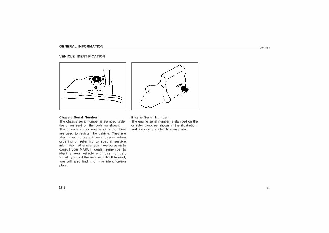
104
797-74E-I
VEHICLE IDENTIFICATION
Engine Serial NumberThe engine serial number is stamped on thecylinder block as shown in the illustrationand also on the identification plate.
Chassis Serial NumberThe chassis serial number is stamped underthe driver seat on the body as shown.The chassis and/or engine serial numbersare used to register the vehicle. They arealso used to assist your dealer whenordering or referring to special serviceinformation. Whenever you have occasion toconsult your MARUTI dealer, remember toidentify your vehicle with this number.Should you find the number difficult to read,you will also find it on the identificationplate.
GENERAL INFORMATION
12-1
105
797-74E-I SPECIFICATIONS
13
SPECIFICATIONS
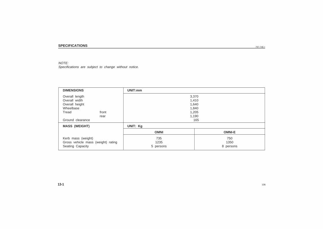
106
797-74E-I
13-1
SPECIFICATIONS
NOTE:Specifications are subject to change without notice.
DIMENSIONS UNIT:mm
Overall length 3,370Overall width 1,410Overall height 1,640Wheelbase 1,840Tread front 1,205
rear 1,190Ground clearance 165
MASS (WEIGHT) UNIT: Kg
OMNI OMNI-E
Kerb mass (weight) 735 750Gross vehicle mass (weight) rating 1235 1350Seating Capacity 5 persons 8 persons
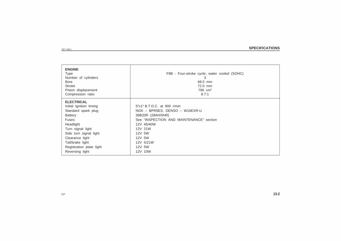
107
797-74E-I SPECIFICATIONS
13-2
ENGINEType F8B - Four-stroke cycle, water cooled (SOHC)Number of cylinders 3Bore 68.5 mmStroke 72.0 mmPiston displacement 796 cm3
Compression ratio 8.7:1
ELECTRICALInitial Ignition timing 50±10 B.T.D.C. at 900 r/minStandard spark plug NGK – BPR5ES, DENSO – W16EXR-UBattery 38B20R (28AH/5HR)Fuses See “INSPECTION AND MAINTENANCE” sectionHeadlight 12V 45/40WTurn signal light 12V 21WSide turn signal light 12V 5WClearance light 12V 5WTail/brake light 12V 5/21WRegistration plate light 12V 5WReversing light 12V 10W
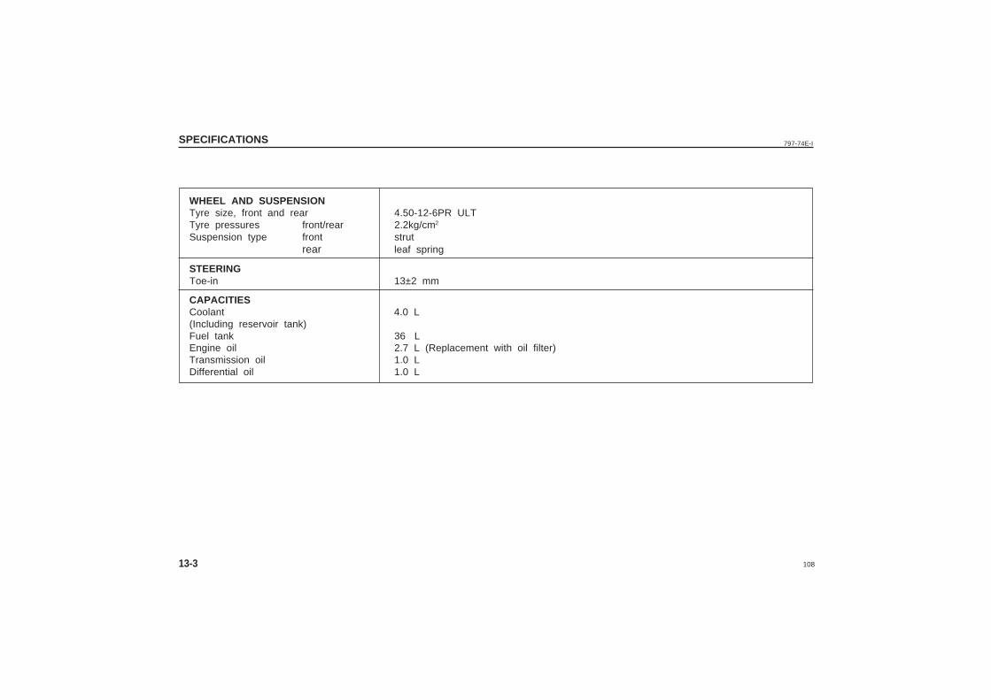
108
797-74E-I
13-3
SPECIFICATIONS
WHEEL AND SUSPENSIONTyre size, front and rear 4.50-12-6PR ULTTyre pressures front/rear 2.2kg/cm2
Suspension type front strutrear leaf spring
STEERINGToe-in 13±2 mm
CAPACITIESCoolant 4.0 L(Including reservoir tank)Fuel tank 36 LEngine oil 2.7 L (Replacement with oil filter)Transmission oil 1.0 LDifferential oil 1.0 L
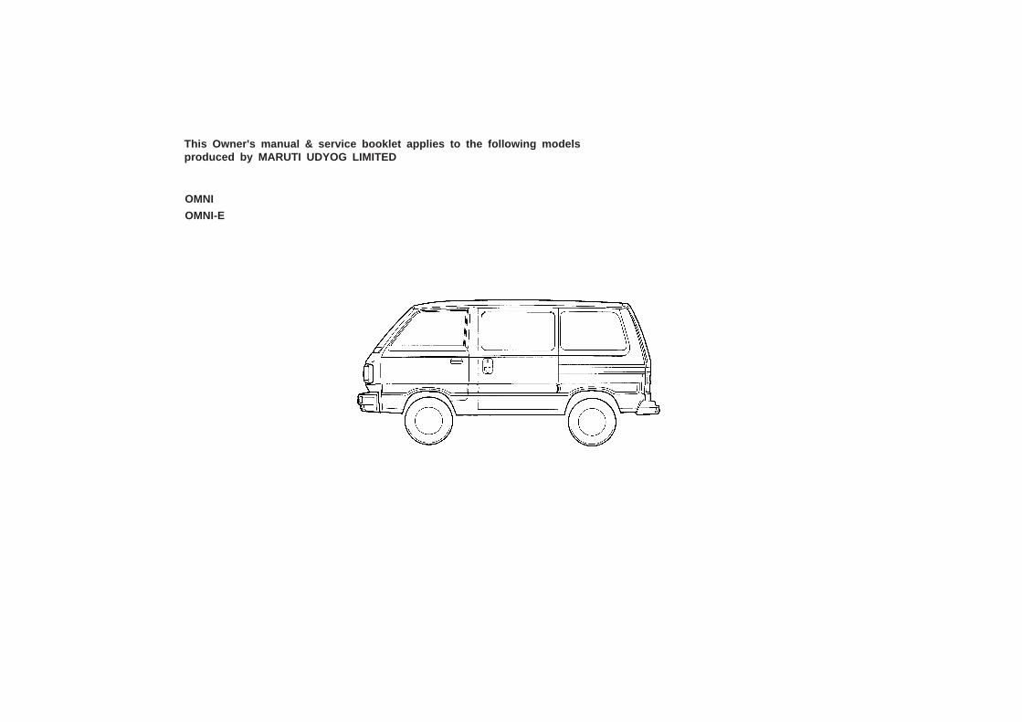
This Owner's manual & service booklet applies to the following modelsproduced by MARUTI UDYOG LIMITED
OMNI
OMNI-E