doc 9905 doc xxxx - icscc.org.cn
TRANSCRIPT

Approved by and published under the authority of the Secretary General
INTERNATIONAL CIVIL AVIATION ORGANIZATION
Doc 9905Required Navigation PerformanceAuthorization Required (RNP AR)Procedure Design ManualSecond Edition, 2016
ORGANIZACIÓN DE AVIACIÓN CIVIL INTERNACIONAL
Doc XXXX
Volume X — XXXXXXXXXXXX Edition, 20XX
XXXXXXXXXXXXXXXXXXXXXXX
Aprobada por la Secretaria General y publicada bajo su responsabilidad
Doc XXXX
XXXXXXXX
Approved by and published under the authority of the Secretary General
Doc XXXX
Volume X — XXXXXXXXXXXX Edition, 20XX
XXXXXXXXXXXXXXXXXXXXXXX
Doc XXXX
Volume X — XXXXXXXXXXXX Edition, 20XX
XXXXXXXXXXXXXXXXXXXXXXX
Утверждено Генеральным секретарем и опубликовано с его санкции
Международная организация гражданской авиации
Doc XXXX
Volume X — XXXXXXXXXXXX Edition, 20XX
Approuvé par la Secrétaire générale et publié sous son autorité
ORGANISATION DE L’AVIATION CIVILE INTERNATIONALE
XXXXXXXXXXXXXXXXXXXXXXX


Approved by and published under the authority of the Secretary General
INTERNATIONAL CIVIL AVIATION ORGANIZATION
Doc 9905
Second Edition, 2016
Required Navigation PerformanceAuthorization Required (RNP AR)Procedure Design Manual
Published in separate English, Arabic, Chinese, French, Russian and Spanish editions by the
INTERNATIONAL CIVIL AVIATION ORGANIZATION 999 University Street, Montréal, Quebec, Canada H3C 5H7
For ordering information and for a complete listing of sales agents
and booksellers, please go to the ICAO website at www.icao.int
First edition 2009 Second edition 2016
Doc 9905, Required Navigation Performance Authorization Required (RNP AR) Procedure Design Manual Order Number: 9905
ISBN
© ICAO 2016
All rights reserved. No part of this publication may be reproduced, stored in a
permission in writing from the International Civil Aviation Organization.
(iii)
AMENDMENTS
Amendments are announced in the supplements to the Catalogue of ICAO Publications; the Catalogue and its supplements are available on the ICAO website at www.icao.int. The space below is provided to keep a record of such amendments.
RECORD OF AMENDMENTS AND CORRIGENDA
AMENDMENTS CORRIGENDA
No. Date Entered by No. Date Entered by


(v)
TABLE OF CONTENTS
Page FOREWORD ..................................................................................................................................................... (vii)
DEFINITIONS .................................................................................................................................................... (ix)
ABBREVIATIONS AND ACRONYMS ............................................................................................................... (xiii)
Chapter 1. Description of required navigation performance authorization required (RNP AR) ............ 1-1
1.1 Purpose of the manual ...................................................................................................................... 1-1
1.2 Application ........................................................................................................................................ 1-1
1.3 Aircraft qualification .......................................................................................................................... 1-2
1.4 Operational qualification ................................................................................................................... 1-2
1.5 Flight operations information ............................................................................................................. 1-3
1.6 Flight procedures .............................................................................................................................. 1-3
Chapter 2. RNP AR approach procedure design ....................................................................................... 2-1
2.1 Underlying principles......................................................................................................................... 2-1
2.2 Obstacle clearance altitude/height (OCA/H) and decision altitude/height (DA/H) ............................. 2-1
2.3 Standard conditions .......................................................................................................................... 2-2
2.4 Terrain effects ................................................................................................................................... 2-2
2.5 Lateral protection .............................................................................................................................. 2-2
2.6 Vertical protection ............................................................................................................................. 2-3
Chapter 3. General criteria ........................................................................................................................... 3-1
3.1 Aircraft speed categories .................................................................................................................. 3-1
3.2 Calculating turn radius and bank angle ............................................................................................. 3-3
Chapter 4. Procedure construction ............................................................................................................. 4-1
4.1 General principles ............................................................................................................................. 4-1
4.2 Initial approach segment ................................................................................................................... 4-14
4.3 Holding .............................................................................................................................................. 4-16
4.4 Intermediate approach segment ....................................................................................................... 4-16
4.5 FAS ................................................................................................................................................... 4-18
4.6 Missed approach segment (MAS) ..................................................................................................... 4-32
4.7 Determination of OCA/H ................................................................................................................... 4-43
(vi) RNP AR Procedure Design Manual
Chapter 5. Publication and charting ........................................................................................................... 5-1
5.1 Introduction ....................................................................................................................................... 5-1
5.2 Aeronautical chart titles ..................................................................................................................... 5-1
5.3 Approach chart identification ............................................................................................................. 5-1
5.4 Chart notes ....................................................................................................................................... 5-1
5.5 Depiction ........................................................................................................................................... 5-2
5.6 Minima .............................................................................................................................................. 5-2
Appendix 1. Vertical error budget (VEB) minimum obstacle clearance (MOC) equation explanation (SI units) ...................................................................................................................... APP 1-1
Appendix 2. Vertical error budget (VEB) minimum obstacle clearance (MOC) equation explanation (non-SI units) ............................................................................................................... APP 2-1
_____________________

(vii)
FOREWORD
Required navigation performance (RNP) was initially envisaged by the International Civil Aviation Organization (ICAO)
as a means to facilitate change in airspace operation. ICAO recognized that global navigation satellite systems, the
navigation infrastructure, operations, and aircraft systems were undergoing change faster than could be supported by
their traditional technical standards processes. RNP was developed to allow the specification of airspace and operation
requirements without the constraints of the slow process for specifying equipment and systems.
Initially, in order to support RNP operations, RNP procedure design criteria were developed and incorporated in the
Procedures for Air Navigation Services — Aircraft Operations (PANS-OPS) (Doc 8168). However, lacking demand and
general familiarity with the change in operations and implementation paradigm possible with RNP, the initial criteria were
conservative in nature and specification. Consequently, as specific locations were identified where demanding RNP
solutions were needed, ICAO criteria were found to be insufficient and lacking in the necessary support guidance for
approving operations.
At the same time, one State in collaboration with industry and a key airline operator undertook the task to develop
criteria that permitted the usage of RNP-capable aircraft to address a significant problem with airport access in obstacle-
rich environments or terrain, under limiting weather conditions. These criteria for RNP procedures were documented in
regulatory guidance, as part of the United States Federal Aviation Administration (FAA) Advisory Circular (AC) 120-29A.
The AC 120-29A RNP criteria permit a significant degree of flexibility and customization in procedure design. It extends
beyond traditional procedure design guidance in its provision of criteria addressing relevant aspects of operational
requirements that must be considered in the implementation of such special flight operations e.g. visual segment
assessment, engine loss, extraction, tailored climb gradient and balked landing. However, such criteria can be very
demanding and time-consuming as it must be evaluated and approved for every application. As a result, it was
determined that a degree of standardization in lieu of maximum variability would facilitate not only procedure
development but implementation as well.
In order to rationalize and support the implementation of RNP operations, ICAO established the Required Navigation
Performance and Special Operational Requirements Study Group (RNPSORSG) which developed the Performance-Based Navigation (PBN) Manual (Doc 9613). The PBN Manual provides two types of navigation specifications for
approach operations: RNP approach (RNP APCH) and RNP authorization required approach (RNP AR APCH). The
RNP APCH navigation specification is intended to satisfy general RNP operational requirements and permit participation
by aircraft with a basic level of RNP capability without a requirement for operational authorization. The other navigation
specification, RNP AR APCH, which enables a higher level of navigation performance better able to address issues of
airport access, such as obstacle-rich environments, and facilitate advances in air traffic management (ATM), requires
the operator to meet additional aircraft and aircrew requirements and obtain operational authorization from the State
regulatory authority.
RNP AR procedures can provide significant operational and safety advantages over other area navigation (RNAV)
procedures by incorporating additional navigational accuracy, integrity and functional capabilities to permit operations
using reduced obstacle clearance tolerances that enable approach and departure procedures to be implemented in
circumstances where other types of approach and departure procedures are not operationally possible or satisfactory.
Procedures implemented in accordance with this manual allow the exploitation of high-quality, managed lateral and
vertical navigation (VNAV) capabilities that provide improvements in operational safety and reduced controlled flight into
terrain (CFIT) risks.

(viii) RNP AR Procedure Design Manual
This manual is intended for use by aircraft operators and procedure designers of instrument approaches based on RNP
using RNAV avionics systems, where authorization is required (AR).
The manual includes design criteria to aid States in the implementation of RNP AR approach procedures in accordance
with the PBN Manual, Volume II, Part C, Chapter 6, Implementing RNP AR APCH. Similar criteria for departure
procedures will be incorporated when developed.
_____________________

(ix)
DEFINITIONS
Aircraft-based augmentation system (ABAS). An augmentation system that augments and/or integrates the
information obtained from the other GNSS elements with information available on board the aircraft.
Note.— The most common form of ABAS is receiver autonomous integrity monitoring (RAIM).
Airspace concept. An airspace concept provides the outline and intended framework of operations within an airspace.
An airspace concept is essentially a high-level statement of an airspace plan. Airspace concepts are developed to
satisfy explicit strategic objectives such as improved safety, increased air traffic capacity and mitigation of
environmental impact. Airspace concepts include details of the practical organization of the airspace and its users
based on particular communications, navigation and surveillance/air traffic management (CNS/ATM) assumptions,
e.g. air traffic services (ATS) route structure, separation minima, route spacing and obstacle clearance.
Approach procedure with vertical guidance (APV). A performance-based navigation (PBN) instrument approach
procedure designed for 3D instrument approach operations Type A.
Area navigation (RNAV). A method of navigation which permits aircraft operation on any desired flight path within the
coverage of ground-based or spaced-based navigation aids or within the limits of the capability of self-contained
aids, or a combination of these.
Note.— Area navigation includes performance-based navigation as well as other operations that do not meet the definition of performance-based navigation.
Area navigation route. An ATS route established for the use of aircraft capable of employing area navigation.
ATS surveillance service. Term used to indicate a service provided directly by means of an ATS surveillance system.
ATS surveillance system. A generic term meaning variously, ADS-B, PSR, SSR or any comparable ground-based
system that enables the identification of aircraft.
Note.— A comparable ground-based system is one that has been demonstrated, by comparative assessment or other methodology, to have a level of safety and performance equal to or better than monopulse SSR.
Cyclic redundancy checking (CRC). A mathematical algorithm applied to the digital expression of data that provides a level of assurance against loss or alteration of data.
Datum crossing point (DCP). The DCP is a point on the glide path directly above the LTP or FTP at a height specified
by the RDH.
Decision altitude (DA) or decision height (DH). A specified altitude or height in a 3D instrument approach operation at
which a missed approach must be initiated if the required visual reference to continue the approach has not been
established.
Note 1.— DA is referenced to mean sea level and DH is referenced to the threshold elevation.
(x) RNP AR Procedure Design Manual
Note 2.— The required visual reference means that section of the visual aids or of the approach area which should have been in view for sufficient time for the pilot to have made an assessment of the aircraft position and rate of change of position, in relation to the desired flight path. In Category III operations with a decision height the required visual reference is that specified for the particular procedure and operation. Note 3.— For convenience where both expressions are used they may be written in the form “decision altitude/height” and abbreviated “DA/H”. Mixed navigation environment. An environment where different navigation specifications may be applied within the
same airspace (e.g. RNP 10 routes and RNP 4 routes in the same airspace) or where operations using
conventional navigation are allowed together with RNAV or RNP applications.
Navigation aid (NAVAID) infrastructure. Navaid infrastructure refers to space-based and or ground-based navigation
aids available to meet the requirements in a navigation specification.
Navigation application. The application of a navigation specification and the supporting navaid infrastructure to routes,
procedures, and/or defined airspace volume, in accordance with the intended airspace concept.
Note.— The navigation application is one element, along with communication, surveillance and ATM procedures meeting the strategic objectives in a defined airspace concept. Navigation function. The detailed capability of the navigation system (such as the execution of leg transitions, parallel
offset capabilities, holding patterns, navigation databases) required to meet the airspace concept.
Note.— Navigational functional requirements are one of the drivers for selection of a particular navigation specification. Navigation functionalities (functional requirements) for each navigation specification can be found in the
Performance-Based Navigation (PBN) Manual (Doc 9613), Volume II, Parts B and C. Navigation specification. A set of aircraft and air crew requirements needed to support performance-based navigation
operations within a defined airspace. There are two kinds of navigation specifications:
RNP specification. A navigation specification based on area navigation that includes the requirement for
performance monitoring and alerting, designated by the prefix RNP, e.g. RNP 4, RNP APCH.
RNAV specification. A navigation specification based on area navigation that does not include the requirement for
performance monitoring and alerting, designated by the prefix RNAV, e.g. RNAV 5, RNAV 1.
Note.— The Performance-Based Navigation (PBN) Manual (Doc 9613), Volume II, contains detailed guidance on navigation specifications. Obstacle clearance surface (OCS). An obstacle evaluation surface used to determine the minimum obstacle clearance
altitude at any point.
Performance-based navigation (PBN). Area navigation based on performance requirements for aircraft operating
along an ATS route, on an instrument approach procedure or in a designated airspace.
Note.— Performance requirements are expressed in navigation specifications in terms of accuracy, integrity, continuity, availability and functionality needed for the proposed operation in the context of a particular airspace concept.
Definitions (xi)
Procedural control. Air traffic control service provided by using information derived from sources other than an ATS
surveillance system.
RNAV operations. Aircraft operations using an area navigation system for RNAV applications. RNAV operations include
the use of area navigation for operations which are not developed in accordance with the Performance-Based
Navigation (PBN) Manual (Doc 9613).
RNAV system. A navigation system which permits aircraft operation on any desired flight path within the coverage of
station-referenced navigation aids or within the limits of the capability of self-contained aids, or a combination of
these. An RNAV system may be included as part of a flight management system (FMS).
RNAV operations. Aircraft operations using an area navigation system for RNAV applications. RNAV operations include
the use of area navigation for operations which are not developed in accordance with the Performance-Based
Navigation (PBN) Manual (Doc 9613).RNP operations. Aircraft operations using an RNP system for RNP
applications.
RNP system. An area navigation system which supports on-board performance monitoring and alerting.
Satellite based augmentation system (SBAS). A wide coverage augmentation system in which the user receives
augmentation from a satellite-based transmitter.
Standard instrument arrival (STAR). A designated instrument flight rule (IFR) arrival route linking a significant point,
normally on an ATS route, with a point from which a published instrument approach procedure can be commenced.
Standard instrument departure (SID). A designated instrument flight rule (IFR) departure route linking the aerodrome
or a specified runway of the aerodrome with a specified significant point, normally on a designated ATS route, at
which the en-route phase of a flight commences.
Vertical path angle (VPA). Angle of the published final approach descent in Baro-VNAV procedures.
_____________________

(xiii)
ABBREVIATIONS AND ACRONYMS
AC Advisory circular
ADS-B Automatic dependent surveillance broadcast
AGL Above ground level
anpe Actual navigation performance error
APCH Approach
APV Approach procedure with vertical guidance
AR Authorization required
*ase Altimetry system error
ASI Airspeed indicator
ATC Air traffic control
*atis Automatic terminal information service
ATM Air traffic management
ATS Air traffic services
ATT Along track tolerance
BARO-VNAV Barometric vertical navigation
BG Body geometry
CAT Category
CDA Continuous descent approach
CFIT Controlled flight into terrain
Cot Cotangent
CNS/ATM Communications, navigation and surveillance/air traffic management
DA/H Decision altitude/height
DCP Datum crossing point
DER Departure end of runway
DFAP Distance from threshold to FAP
DFROP Distance to final approach roll-out point
DR Descent rate
DTA Distance of turn anticipation
FAA Federal Aviation Administration
FAF Final approach fix
FAP Final approach point
FAS Final approach segment
FCC Flight control computer
FOSA Flight operations safety assessment
FROP Final approach roll-out point
ft Feet
*fte Flight technical error
FTP Fictitious threshold point
GNSS Global navigation satellite system
GP Glide path
GPI Ground point of intercept
* Lower case is used for those abbreviations and acronyms that come from the Performance-Based Navigation (PBN) Manual
(Doc 9613).

(xiv) RNP AR Procedure Design Manual
GPS Global positioning system
H Altitude
HATh Height above threshold
HL Height loss
IAF Initial approach fix
IAS Indicated airspeed
IF Intermediate fix
IRU Inertial reference unit
ISA International standard atmosphere
isad International standard atmosphere temperature deviation
km Kilometre
kt Knot
LNAV Lateral navigation
LTP Landing threshold point
LTPELEV Landing threshold point elevation
m Metre
MA Missed approach
MAS Missed approach segment(s)
MEL Minimum equipment list
MOC Minimum obstacle clearance
NM Nautical mile
OAS Obstacle assessment surface(s)
OCA/H Obstacle clearance altitude/height
OCS Obstacle clearance surface
PANS-OPS Procedures for Air Navigation Services — Aircraft Operations
PBN Performance-based navigation
PSR Primary surveillance radar
R Rate of turn
r Radius
RA Radio altimeter
RDH Reference datum height
RF Radius to fix (ARINC leg type)
RNAV Area navigation
RNP Required navigation performance
RNP AR Required navigation performance authorization required
RNPSORSG Required Navigation Performance and Special Operational Requirements Study Group
RSS Root sum square
RWY Runway
SI International system of units
SOC Start of climb
SSR Secondary surveillance radar
TAS True airspeed
TCH Threshold crossing height
TF Track to fix (ARINC leg type)
TP Turning point
TrD Transition distance
TWC Tailwind component
V Speed
VA Heading to altitude (ARINC leg type)
vae Vertical angle error
Vat Speed at threshold
VEB Vertical error budget

Abbreviations and acronyms (xv)
VGSI Visual glide slope indicator
VNAV Vertical navigation
VPA Vertical path angle
Vslg Stall speed in landing configuration at maximum landing mass
Vso Stall speed
WGS World geodetic system
wpr Waypoint precision error
_____________________

1-1
Chapter 1
DESCRIPTION OF REQUIRED NAVIGATION PERFORMANCE AUTHORIZATION REQUIRED (RNP AR)
1.1 PURPOSE OF THE MANUAL
1.1.1 This manual is intended for use by aircraft operators and procedure designers of instrument approaches
based on required navigation performance (RNP) using area navigation (RNAV) avionics systems, where authorization
is required (AR).
1.1.2 The manual includes design criteria to aid States in the implementation of RNP AR approach (APCH)
procedures in accordance with Performance-Based Navigation (PBN) Manual (Doc 9613) (hereafter referred to as the
PBN Manual), Volume II, Part C, Chapter 6, Implementing RNP AR APCH.
1.2 APPLICATION
1.2.1 Implementation of RNP AR procedures extends beyond procedure design in that an authorization process
for aircraft operators is necessary to ensure that other critical dependencies and associated airworthiness and
operational procedure approvals are complete prior to implementation. Guidance on implementation and operational
approval is provided in the PBN Manual.
1.2.2 The PBN Manual contains navigation specifications applicable to two RNP approach applications: RNP
APCH and RNP AR APCH.
1.2.3 RNP AR APCH operations are classified as approach procedures with vertical guidance (APVs) in
accordance with Annex 6 — Operation of Aircraft. This type of operation requires a positive vertical navigation (VNAV)
guidance system for the final approach segment (FAS). The procedure design criteria in the manual are based on
utilization of a barometric vertical navigation system (BARO-VNAV) meeting specified airworthiness requirements.
Obstacle clearance is based on a statistical assessment of all the component errors referred to as a vertical error budget
(VEB). Other suitably accurate vertical guidance may be implemented provided equivalent accuracy, integrity and
containment can be assured. SBAS avionics meeting specified airworthiness requirements can be used as an alternate
means of providing vertical guidance on RNP AR approaches designed in accordance with these criteria.
1.2.4 RNP AR APCH procedures may be designed to support multiple minima for various appropriate RNP, e.g.
RNP 0.3, RNP 0.2, down to RNP 0.1. However, designers should not promulgate procedures with RNP less than 0.3
unless there is an operational benefit. Reductions in RNP reduce the alert limits and increase the possibility of an alert
and a consequent go-around; therefore, the minimum RNP published should not be smaller than necessary to provide
the required operational capability.
1.2.5 The design criteria in this manual are applicable to a range of aircraft types and cannot; therefore, take into
account the full capability of some aircraft types. Consequently, procedures designed in accordance with this manual will
provide an acceptable operational solution in many but not all circumstances. Where an operationally acceptable
solution is not available through the application of these criteria, development of detailed procedures may be needed to

1-2 RNP AR Procedure Design Manual
satisfy local conditions. Alternative design solutions may be derived which specify aircraft type or specific performance
parameters, special operating conditions or limitations, crew training, operational evaluation or other requirements that
can be demonstrated to provide an equivalent level of safety. Such solutions are not the subject of this manual and
require a case-by-case flight operations safety assessment (FOSA) and operational approval.
1.2.6 RNP AR APCH operations utilize high levels of RNAV capability, and all aspects of the operation must
meet the relevant requirements specified in the PBN Manual.
1.2.7 The safety of RNP AR APCH procedures is dependent upon the proper inter-relationship between aircraft
capability, operating procedures and procedure design. Users of this manual should understand this critical difference in
the design of RNP AR procedures.
1.3 AIRCRAFT QUALIFICATION
1.3.1 Aircraft qualification is integral to the process of authorization for RNP AR operations. For an RNP AR
instrument flight procedure, only aircraft that have demonstrated performance, capability and functionality can be
authorized to conduct RNP AR APCH operations.
1.3.2 Aircraft must meet the requirements of the RNP AR APCH navigation specification given in the PBN
Manual. Aircraft manufacturers must demonstrate and document aircraft performance and capability, and any special
procedures or limitations associated with the aircraft and systems as part of either an aircraft certification programme or
aircraft compliance assessment.
1.3.3 The demonstration of aircraft capability allows all qualified aircraft to use the instrument flight procedure,
relieving the designer of the need to consider individual aircraft types or performance capabilities.
1.3.4 As aircraft performance, integrity and functionality are demonstrated, documented and approved as part of
the demonstration of RNP AR capability, the conduct of special or extensive flight trials and simulations to gather
statistical evidence of the aircraft performance is not required to support the implementation of RNP AR operations.
1.4 OPERATIONAL QUALIFICATION
1.4.1 The authorization process for RNP AR APCH operations includes the approval of operating procedures
and crew training in accordance with the RNP AR APCH navigation specification given in the PBN Manual.
1.4.2 Operating procedures must conform to any conditions in the aircraft RNP AR capability approval and any
additional requirement such as a minimum equipment list (MEL), flight crew operations manuals, aircraft flight manuals
and maintenance guidance.
1.4.3 Operating procedures must also take into account any limitations or requirements specified by the
procedure designer. Specified equipment or capabilities may be required to conduct an RNP AR APCH procedure in
certain cases.
1.4.4 Individual RNP AR APCH procedures are validated in accordance with the PBN Manual and other relevant
guidance prior to publication. However, as variations may occur in functionality, equipment and flyability, operators are
required to conduct an operational validation of each of the procedures applicable to the type of aircraft operated.
1.4.5 Prior to authorization for the conduct of RNP AR APCH operations, an operator must demonstrate to the
State regulator that all appropriate elements of the RNP AR APCH operations have been appropriately addressed
including:
Chapter 1. Description of RNP AR 1-3
a) determination of aircraft qualification;
b) training e.g. flight crews, dispatch;
c) MEL, continuing airworthiness;
d) requirements for operational procedures;
e) dispatch procedures;
f) maintenance procedures;
g) conditions or limitations for approval;
h) procedure operational validation for each aircraft type; and
i) conduct of a FOSA.
1.4.6 The specific considerations and issues for these areas are as described in detail in the PBN Manual.
1.5 FLIGHT OPERATIONS INFORMATION
1.5.1 The conduct of RNP AR instrument procedures requires that the aircraft operator examine its crew
information, flight procedures and training to ensure that they are sufficient to enable operator qualification and
operational approval.
1.5.2 Crew information, flight procedures and training must be suitable for the RNP AR APCH instrument
approach procedures, aircraft type(s) or variants, crew positions, airborne systems, navaids and ground systems to be
used. Training topics will be tailored to suit their application to initial qualification, recurrent qualification, requalification,
command training upgrade or differences qualification, as applicable. Crew training requirements are detailed in the PBN
Manual.
1.6 FLIGHT PROCEDURES
Users of this manual must be familiar with the following aspects associated with RNP AR APCH operations.
a) RNP capability. Crews must be aware of the aircraft RNP capability documented in the RNP AR
authorization appropriate to the aircraft configuration or operational procedures (e.g. global positioning
system (GPS) inoperative, use of flight director instead of autopilot).
b) RNP availability check. Prior to the commencement of an approach, the crew is responsible for
ensuring that the appropriate RNP is selected. The RNP with the least stringent navigation accuracy
requirement meeting all the requirements of the approach procedures and consistent with the
operating conditions should be selected to reduce the possibility of alerts and consequent missed
approaches. Crews will ensure prior to commencement of a procedure that the required navigation
system performance is available and can be expected to be available through the conduct of the
procedure. RNP should not be changed after commencement of the procedure.
1-4 RNP AR Procedure Design Manual
c) Radius to fix (RF) legs. The use of RF legs provides more flexibility in the design of the procedure
track. RF legs may be present in all phases of the procedure including the final segment, and the
requirement for RF leg capability, if applicable, will be annotated in the PBN requirements box on the
approach chart. As the use of RF legs in the design of procedures is optional, capability to fly
procedures incorporating RF legs must be specifically identified in the operator authorization.
d) Minimum equipment. Minimum equipment provisions are detailed in the PBN Manual. At some
locations, the airspace or obstacle environment will require RNP capability during a missed approach
from anywhere on the procedure. At these locations redundant equipment may be required.
e) Non-standard speeds or climb gradients. RNP AR approaches are developed based on standard
approach speeds and specified a nominal climb gradient in the missed approach. Any exceptions to
these standards must be indicated on the approach procedure, and the operator must ensure they can
comply with any published restrictions before conducting the operation.
f) Non-normal operations. Crews must be competent to contain the aircraft position within tracking
tolerances consistent with the selected RNP during all normal and non-normal operations. (Flight
technical tolerances are specified in the navigation specifications given in the PBN Manual, Volume II,
Chapter 6.)
g) Vertical flight path tolerances. In the FAS, crews will monitor any vertical deviation from the VNAV
path to ensure that the aircraft remains within the tolerances specified in the navigation specifications
given in the PBN Manual, Volume II, Chapter 6.
h) Coupled autopilot. Use of coupled autopilot is recommended. Operator procedures must specify the
conditions for operations without autopilot.
_____________________
2-1
Chapter 2
RNP AR APPROACH PROCEDURE DESIGN
2.1 UNDERLYING PRINCIPLES
RNP APCH versus RNP AR APCH
2.1.1 RNP APCH is defined as an RNP approach procedure that requires a lateral TSE of +/-1 NM in the initial,
intermediate and missed approach segments (MAS) and a lateral TSE of ±0.3 NM in the FAS. Guidance on
implementing RNP APCH operations can be found in the PBN Manual, Volume II, Chapter 5, Implementing RNP APCH.
2.1.2 RNP AR APCH is defined as an RNP approach procedure that requires a lateral TSE as low as ±0.1 NM
on any segment of the approach procedure. RNP AR APCH procedures also require that a specific vertical accuracy be
maintained as detailed in the PBN Manual, Volume II, Part B, Chapter 6. The datum crossing point (DCP) for RNP AR
procedures is the point located above the landing threshold point (LTP) or the fictitious threshold point (FTP). The RNP
AR APCH criteria apply only to those aircraft and operators complying with specified additional certification, approval
and training requirements. RNP AR APCH procedures are only published where significant operational advantages can
be achieved while preserving or improving safety of operation. The RNP AR certification and approval requirements are
contained in the PBN Manual. For the purposes of applying the criteria contained in this manual, RNP AR procedure
obstacle protection is associated with RNP navigation accuracy requirements. The RNP navigation accuracy
requirement is used to determine the area semi-width value (in NM) of a protection area associated with a segment of an
instrument procedure.
2.2 OBSTACLE CLEARANCE ALTITUDE/HEIGHT (OCA/H)
AND DECISION ALTITUDE/HEIGHT (DA/H)
2.2.1 An OCA/H is published for RNP AR procedures on the chart; however, for procedures involving an MAS
with RNP navigation accuracy requirements less than 1.0 NM, the DA/H is published instead, and the appropriate
notation is entered on the chart. In this case, the approval process is intended to ensure that the final approach RNP is
continued until the point where the nominal DA/H occurs.
DA/H lower limit
2.2.2 Since RNP AR approach procedures are designed for 3D instrument approach operations Type A, the
lowest possible DH is 250 ft.
Procedure complexity and OCA/H values below 75 m (246 ft)
2.2.3 If an OCH of 75 m (246 ft) is obtained using a straight-in approach, the procedure should not be further
complicated by adding RF turns or reducing RNP solely to obtain lower OCH values.

2-2 RNP AR Procedure Design Manual
2.3 STANDARD CONDITIONS
OCA/H is promulgated for those categories of aircraft for which the procedure is designed. The OCH values shall be
based on the following standard conditions:
a) final approach vertical guidance and DA/H are based on pressure altimeter;
b) procedure is flown using flight director or autopilot;
c) aircraft dimensions are considered in certification (no additional procedure design action is required);
d) early go-around or missed approach is safeguarded by the certification and approval process; and
e) aircraft are appropriately certificated and approved by the appropriate authority for RNP AR
operations.
2.4 TERRAIN EFFECTS The application of the VEB for obstacle protection relies on accurate altimetry. Rapidly rising terrain, significant
ridgelines or cliffs, steep valley walls and deep canyons may be associated with Bernoulli/Venturi/orographic lifting
effects that can impact vertical performance. Areas where significant variations in pressure may occur must be identified
during the design process, and their effect on the proposed procedure must be considered during the design process
and validated in the safety assessment.
2.5 LATERAL PROTECTION
For RNP AR procedures, the semi-width of the primary area is defined as 2 × RNP navigation accuracy requirement.
There are no buffer or secondary areas. Table 2-1 lists RNP navigation accuracy requirements applicable to the specific
instrument procedure segments.
Table 2-1. RNP navigation accuracy requirements
RNP AR
Segment Maximum Standard Minimum
Arrival 2 2 1.0
Initial 1 1 0.1
Intermediate 1 1 0.1
Final 0.5 0.3 0.1
Missed approach 1.0 1.0 0.1*
*See section 4.6 for limitations associated with MAS most
stringent RNP navigation accuracy requirements.
Chapter 2. RNP AR approach procedure design 2-3
2.6 VERTICAL PROTECTION
2.6.1 In the final approach and MAS, obstacle clearance is provided by two obstacle assessment surfaces
(OAS):
a) a final approach surface based on the VEB of the barometric altimeter system; and
b) a horizontal surface based on a transition distance (TrD) (see 4.6.9), and a missed approach (Z)
surface.
2.6.2 The certification, approval and training processes are designed to ensure barometric altimeter and crew
performance are adequate to remain within this vertical profile.
_____________________

3-1
Chapter 3
GENERAL CRITERIA
3.1 AIRCRAFT SPEED CATEGORIES
3.1.1 Aircraft performance differences have a direct effect on the airspace and visibility required for manoeuvres
such as circling approach, turning missed approach, final approach descent and manoeuvering to land (including base
and procedure turns). The most significant factor in performance is speed. Accordingly, five categories of typical aircraft
have been established to provide a standardized basis for relating aircraft manoeuvrability to specific instrument
approach procedures.
3.1.2 The landing configuration which is to be taken into consideration shall be defined by the operator or by the
airplane manufacturer.
3.1.3 Aircraft categories will be referred to throughout this document by their letter designations as follows:
• Category A — less than 169 km/h (91 kt) indicated airspeed (IAS)
• Category B — 169 km/h (91 kt) or more but less than 224 km/h (121 kt) IAS
• Category C — 224 km/h (121 kt) or more but less than 261 km/h (141 kt) IAS
• Category D — 261 km/h (141 kt) or more but less than 307 km/h (166 kt) IAS
• Category E — 307 km/h (166 kt) or more but less than 391 km/h (211 kt) IAS
Note.— If the rotorcraft and crew are certified and meet the RNP AR procedure requirements, rotorcraft may be used to fly aircraft Category A RNP AR procedures.
3.1.4 The criterion taken into consideration for the classification of aeroplanes by categories is the IAS at
threshold (Vat) which is equal to the stall speed (Vso) multiplied by 1.3 or stall speed, in landing configuration at maximum
certificated landing mass (Vso) multiplied by 1.23. If both Vso and Vslg are available, the higher resulting speed at
threshold (Vat) is used. The ranges of speeds (IAS) in Tables 3-1 a) and 3-1 b) are to be used in calculating procedures.
For conversion of these speeds to TAS, see 3.1.7.
Restriction on aircraft category and IAS
3.1.5 Where airspace requirements are critical for a specific category of aircraft, procedures may be based on
lower speed category aircraft, provided use of the procedure is restricted to those categories. Alternatively, the
procedure may be designated as limited to a specific maximum IAS for a particular segment without reference to
category. True airspeed (TAS) should be calculated using the procedure speeds given in Tables 3-1 a) and 3-1 b).
3-2 RNP AR Procedure Design Manual
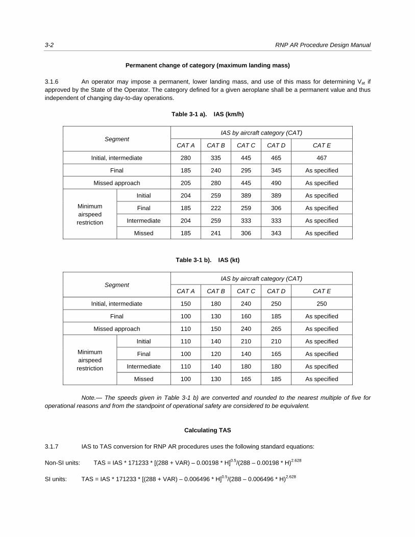
Permanent change of category (maximum landing mass)
3.1.6 An operator may impose a permanent, lower landing mass, and use of this mass for determining Vat if
approved by the State of the Operator. The category defined for a given aeroplane shall be a permanent value and thus
independent of changing day-to-day operations.
Table 3-1 a). IAS (km/h)
Segment IAS by aircraft category (CAT)
CAT A CAT B CAT C CAT D CAT E
Initial, intermediate 280 335 445 465 467
Final 185 240 295 345 As specified
Missed approach 205 280 445 490 As specified
Minimum
airspeed
restriction
Initial 204 259 389 389 As specified
Final 185 222 259 306 As specified
Intermediate 204 259 333 333 As specified
Missed 185 241 306 343 As specified
Table 3-1 b). IAS (kt)
Segment IAS by aircraft category (CAT)
CAT A CAT B CAT C CAT D CAT E
Initial, intermediate 150 180 240 250 250
Final 100 130 160 185 As specified
Missed approach 110 150 240 265 As specified
Minimum
airspeed
restriction
Initial 110 140 210 210 As specified
Final 100 120 140 165 As specified
Intermediate 110 140 180 180 As specified
Missed 100 130 165 185 As specified
Note.— The speeds given in Table 3-1 b) are converted and rounded to the nearest multiple of five for operational reasons and from the standpoint of operational safety are considered to be equivalent.
Calculating TAS
3.1.7 IAS to TAS conversion for RNP AR procedures uses the following standard equations:
Non-SI units: TAS = IAS * 171233 * [(288 + VAR) – 0.00198 * H]0.5
/(288 – 0.00198 * H)2.628
SI units: TAS = IAS * 171233 * [(288 + VAR) – 0.006496 * H]0.5
/(288 – 0.006496 * H)2.628
Chapter 3. General criteria 3-3
where
IAS = indicated airspeed (kt or km/h, as appropriate)
TAS = true airspeed (kt or km/h, as appropriate)
VAR = variation from international standard atmosphere (ISA) (standard value +15) or local data for
95 per cent high temperature, if available
H = altitude (ft or m, as appropriate)
The above equations are incorporated in a Microsoft Excel spreadsheet, which is available together with the electronic
version of the manual on the ICAO public website (www.icao.int) under “Publications”.
3.2 CALCULATING TURN RADIUS AND BANK ANGLE
Speeds for turn calculations
3.2.1 Fly-over waypoints are not permitted between segments of an RNP AR procedure where there are track
changes. For RNP AR procedures, the turn radius for fly-by and RF turns is calculated using a speed V = TAS +
designated tailwind.
3.2.2 Determine the TAS for the turn using formulas in 3.1.7, and the airspeed for the highest aircraft category
from Table 3-1 a) or 3-1 b) for which the procedure is designed.
3.2.3 A speed restriction may be applied to reduce turn radius; however, the maximum speed must be
operationally acceptable for the aircraft intended for the operation. Only one speed restriction per approach segment is
permitted, and the fastest airspeed appropriate for the highest speed category of aircraft for which the procedure is
authorized shall be used to determine that speed.
Calculating the turn radius for fly-by turns
3.2.4 The turn radius applied at fly-by fixes is based on a standard bank angle of 18 degrees at a TAS plus
assumed tailwind. Locate the highest speed aircraft category that will be published on the approach procedure and use
the appropriate IAS in Table 3-1 a) (international system of units (SI)) or Table 3-1 b) (non-SI units), using the highest
altitude allowed in the turn, calculate the TAS using the appropriate formulas in 3.1.7. For initial and intermediate
segments, use the minimum altitude for the fix prior to the turn fix. Use the tailwind component (TWC) from Table 3-2 a)
(SI units) or Table 3-2 b) (non-SI units) for the highest altitude within the turn. (For turns initiated at an altitude located
between values in the table, a new TWC may be interpolated for that turn. If an interpolated wind value is ever used
below 150 m (492 ft), then the 0 ft value for wind begins with 28 km/h (15 kt.))
3.2.5 For the MAS, use the altitude based on a seven per cent gradient with origin at OCA/H – HL (height loss:
nominally 15 m (49 ft)).
3.2.6 Other tailwind gradients, or specific values, may be used after a site-specific determination of wind has
been carried out based on that location’s meteorological history (using available information from other sources). The
source and values used should be documented.
3-4 RNP AR Procedure Design Manual
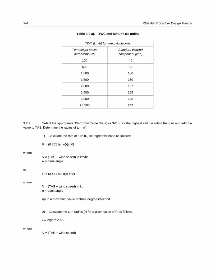
Table 3-2 a). TWC and altitude (SI units)
TWC (km/h) for turn calculations
Turn height above aerodrome (m)
Standard tailwind component (kph)
100 40
500 92
1 000 100
1 500 130
2 000 157
2 500 185
3 000 220
≥3 500 242
3.2.7 Select the appropriate TWC from Table 3-2 a) or 3-2 b) for the highest altitude within the turn and add the
value to TAS. Determine the radius of turn (r).
1) Calculate the rate of turn (R) in degrees/second as follows:
R = (6 355 tan α)/(π*V)
where
V = (TAS + wind speed) in km/h;
α = bank angle
or
R = (3 431 tan α)/( π*V)
where
V = (TAS + wind speed) in kt;
α = bank angle
up to a maximum value of three degrees/second.
2) Calculate the turn radius (r) for a given value of R as follows:
r = V/(20* π* R)
where
V = (TAS + wind speed)

Chapter 3. General criteria 3-5
Table 3-2 b). TWC and altitude (non-SI units)
TWC (kt) for turn calculations
Turn height above aerodrome (ft)
Standard tailwind component (kt)
500 25
1 000 38
1 500 50
2 000 50
2 500 50
3 000 50
3 500 55
4 000 60
4 500 65
5 000 70
5 500 75
6 000 80
6 500 85
7 000 90
7 500 95
8 000 100
8 500 105
9 000 110
9 500 115
10 000 120
10 500 125
≥11 000 130
Turn radii based on non-standard bank angles
3.2.8 The standard design bank angle is 18 degrees. Lower or higher bank angles are allowed for smooth
transitions, maintaining stabilized approaches, lower minima or to achieve specific leg lengths. Non-standard bank
angles must fall in the window of values listed in Table 3-3.
3-6 RNP AR Procedure Design Manual
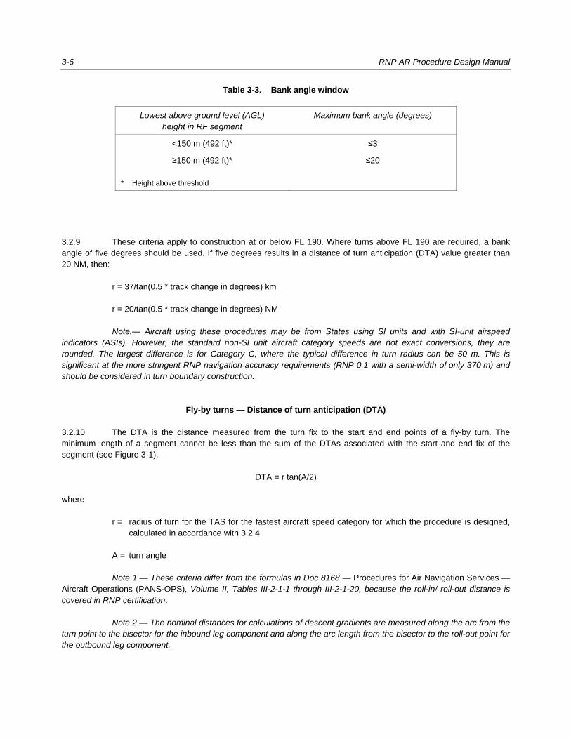
Table 3-3. Bank angle window
Lowest above ground level (AGL) height in RF segment
Maximum bank angle (degrees)
<150 m (492 ft)* ≤3
≥150 m (492 ft)*
* Height above threshold
≤20
3.2.9 These criteria apply to construction at or below FL 190. Where turns above FL 190 are required, a bank
angle of five degrees should be used. If five degrees results in a distance of turn anticipation (DTA) value greater than
20 NM, then:
r = 37/tan(0.5 * track change in degrees) km
r = 20/tan(0.5 * track change in degrees) NM
Note.— Aircraft using these procedures may be from States using SI units and with SI-unit airspeed indicators (ASIs). However, the standard non-SI unit aircraft category speeds are not exact conversions, they are rounded. The largest difference is for Category C, where the typical difference in turn radius can be 50 m. This is significant at the more stringent RNP navigation accuracy requirements (RNP 0.1 with a semi-width of only 370 m) and should be considered in turn boundary construction.
Fly-by turns — Distance of turn anticipation (DTA)
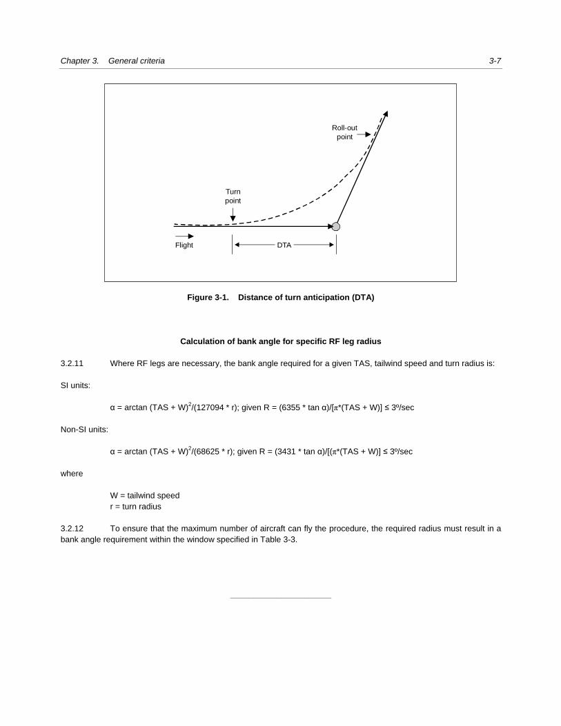
3.2.10 The DTA is the distance measured from the turn fix to the start and end points of a fly-by turn. The
minimum length of a segment cannot be less than the sum of the DTAs associated with the start and end fix of the
segment (see Figure 3-1).
DTA = r tan(A/2)
where
r = radius of turn for the TAS for the fastest aircraft speed category for which the procedure is designed,
calculated in accordance with 3.2.4
A = turn angle
Note 1.— These criteria differ from the formulas in Doc 8168 — Procedures for Air Navigation Services — Aircraft Operations (PANS-OPS), Volume II, Tables III-2-1-1 through III-2-1-20, because the roll-in/ roll-out distance is covered in RNP certification.
Note 2.— The nominal distances for calculations of descent gradients are measured along the arc from the turn point to the bisector for the inbound leg component and along the arc length from the bisector to the roll-out point for the outbound leg component.
Chapter 3. General criteria 3-7
Figure 3-1. Distance of turn anticipation (DTA)
Calculation of bank angle for specific RF leg radius
3.2.11 Where RF legs are necessary, the bank angle required for a given TAS, tailwind speed and turn radius is:
SI units:
α = arctan (TAS + W)2/(127094 * r); given R = (6355 * tan α)/[π*(TAS + W)] ≤ 3º/sec
Non-SI units:
α = arctan (TAS + W)2/(68625 * r); given R = (3431 * tan α)/[(π*(TAS + W)] ≤ 3º/sec
where
W = tailwind speed
r = turn radius
3.2.12 To ensure that the maximum number of aircraft can fly the procedure, the required radius must result in a
bank angle requirement within the window specified in Table 3-3.
______________________
Roll-out
point
Turn
point
Flight DTA

4-1
Chapter 4
PROCEDURE CONSTRUCTION
4.1 GENERAL PRINCIPLES
Segments and legs
4.1.1 The arrival, initial and intermediate segments provide a smooth transition from the en-route environment to
the FAS. Descent to the vertical path intercept and configuring the aircraft for final approach must be accomplished in
these segments. RNP segments should be designed using the most appropriate leg type (track to fix (ARINC leg type)
(TF or RF)) to satisfy obstruction and operational requirements in initial, intermediate, final and MAS. Generally, TF legs
are considered first, but RF legs may be used in lieu of TF-TF turns for turn path control, procedure simplification, or
improved flyability.
Fixes
Fix identification
4.1.2 The fixes used are those in the general criteria. Each fix shall be identified as specified in Annex 15 —
Aeronautical Information Services.
Stepdown fixes
4.1.3 Stepdown fixes are not permitted in RNP AR procedures.
Restrictions on promulgation of RNP AR procedures
Altimeter errors
4.1.4 Final approach vertical guidance is based on barometric altimeters, and therefore procedures shall not be
promulgated for use with remote altimeter setting sources.
Visual segment surface
4.1.5 The visual segment surface must be clear of obstacles in order to publish RNP AR procedures.

4-2 RNP AR Procedure Design Manual
Frame of reference
4.1.6 Positions of obstacles are related to a conventional x, y, z coordinate system with its origin at LTP and
parallel to the world geodetic system (WGS) WGS-84 ellipsoid (see Figure 4-1). The x-axis is parallel to the final
approach track: positive x is the distance before threshold and negative x is the distance after threshold. The y-axis is at
right angles to the x-axis. The z-axis is vertical, heights above threshold being positive.
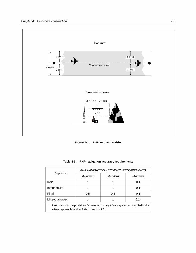
RNP segment width
4.1.7 RNP navigation accuracy requirements are specified in increments of a hundredth (0.01) of a NM.
Segment width is defined as 4 × the RNP navigation accuracy requirement and segment half-width (semi-width) is
defined as 2 × the RNP navigation accuracy requirement (see Figure 4-2). Standard RNP values for instrument
procedures are listed in Table 4-1.
4.1.8 The standard RNP navigation accuracy requirements listed in Table 4-1 should be applied unless a more
stringent navigation accuracy requirement is required to achieve the required ground track or lowest OCA/H. The most
stringent RNP navigation accuracy requirements are listed in the “Minimum” column of Table 4-1.
Figure 4-1. Coordinate system baseline
Orthometric geoidTangent point
z
VPAGPI
LTP orthometricheight
LTP
x
RDH
tan(VPA)
Parallel
Tangent plane
RDH
RDP
Chapter 4. Procedure construction 4-3
Figure 4-2. RNP segment widths
Table 4-1. RNP navigation accuracy requirements
Segment RNP NAVIGATION ACCURACY REQUIREMENTS
Maximum Standard Minimum
Initial 1 1 0.1
Intermediate 1 1 0.1
Final 0.5 0.3 0.1
Missed approach 1 1 0.1*
* Used only with the provisions for minimum, straight final segment as specified in the
missed approach section. Refer to section 4.6.
Plan view
Cross-section view
Course centreline
2 RNP
2 RNP
2 RNP
2 RNP4 RNP
2 × RNP 2 × RNP
MOC

4-4 RNP AR Procedure Design Manual
RNP segment length
4.1.9 Segments should be designed with sufficient length to allow the required descent to be as close to the
optimum gradient as possible and to take account of DTA where turns are required. The minimum straight segment (any
segment) length is 2 × RNP (+DTA, as appropriate, for fly-by turn constructions). Paragraph 4.1.7 applies where RNP
changes occur (RNP value changes 1 × RNP prior to fix). For obstacle clearance calculations, the segment extends
1 × RNP before the first fix to 1 × RNP past the second fix.
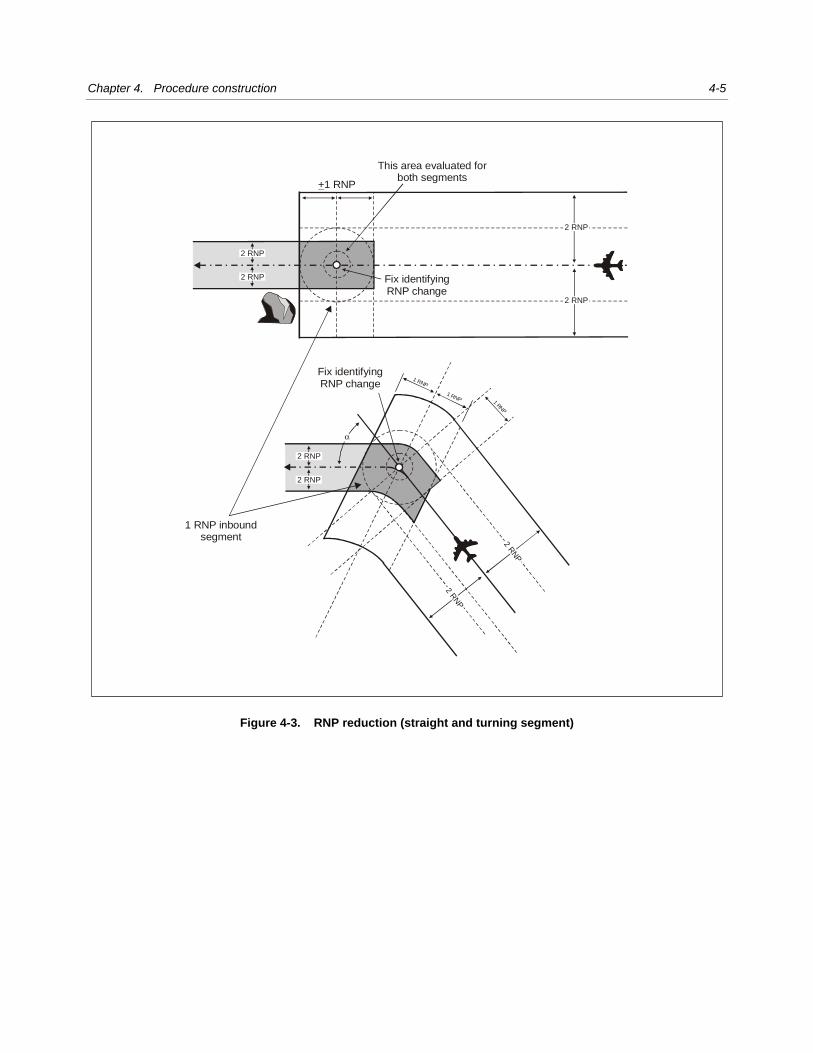
Changing segment width (RNP navigation accuracy requirements)
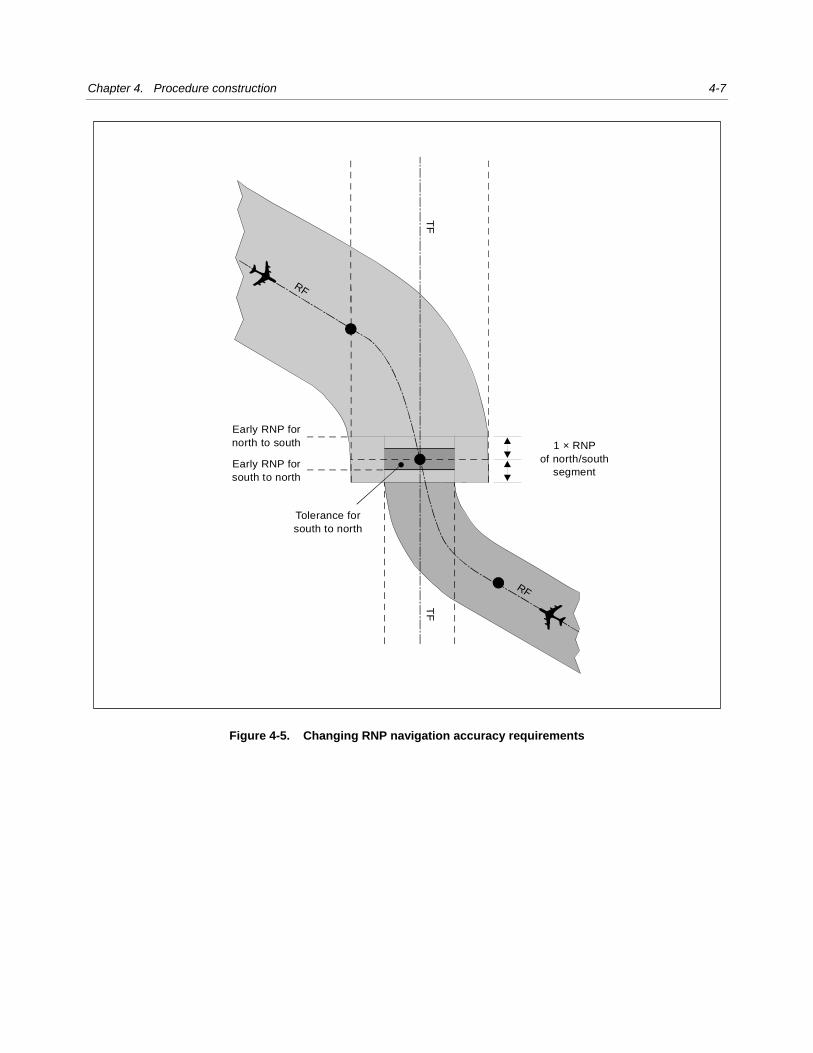
4.1.10 Changes in the RNP navigation accuracy requirements must be completed upon the aircraft reaching the
fix; therefore, the area within ±1 RNP navigation accuracy requirement of the fix must be evaluated for both segments.
The RNP navigation accuracy requirement reduction is illustrated in Figure 4-3, the RNP navigation accuracy
requirement increase is illustrated in Figure 4-4, and RNP navigation accuracy requirement changes involving RF legs
are illustrated in Figure 4-5.
TF leg segment
4.1.11 A TF leg is a geodesic flight path between two fixes and is the normal standard leg used in RNP AR
procedures. TF legs except at the MAPt are linked by fly-by waypoints or RF legs.
Area construction for turns at fly-by waypoints joining two TF legs
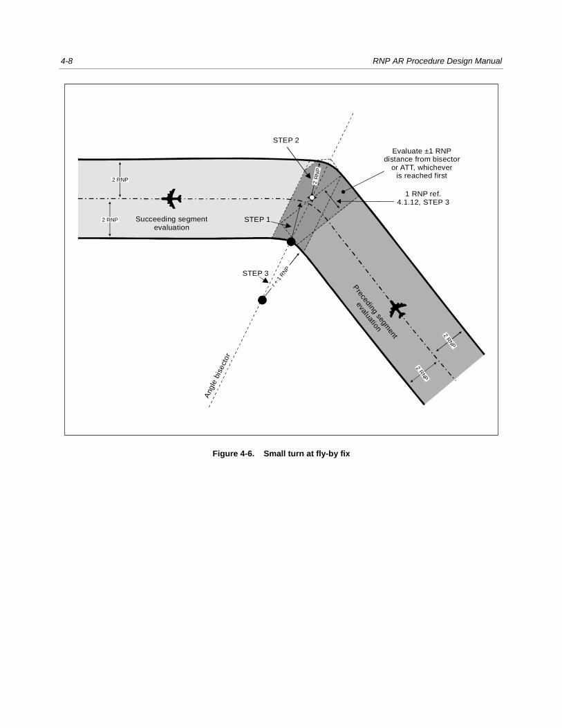
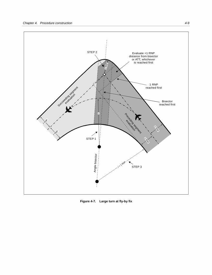
4.1.12 This construction is specific to RNP AR procedures, and only primary areas are used: ½ AW = 2 × RNP;
buffer areas are not applied. Turn angles should be limited to a maximum of 70 degrees where aircraft are expected to
cross (fly-by) the fix at altitudes above FL 190, and to 90 degrees at and below FL 190. When obstructions prevent use
of this construction, use of an RF leg should be considered (see 4.1.13). The fly-by turn area is constructed using the
following steps:
STEP 1: Determine the required ground track. Calculate the turn radius (r) as described in 3.2.4. Construct the
turning flight path tangent to the inbound and outbound legs. The centre will be located on the bisector (see Figures 4-6
and 4-7).
STEP 2: Construct the outer boundary tangential to the inbound and outbound segment outer boundaries, with a
radius of 2 × RNP and centre located at the fix.
STEP 3: Construct the inner turn boundary tangential to the inbound and outbound segment inner boundaries, with
radius of (r + 1 RNP). The centre is located on the bisector (see Figure 4-7).
The evaluation for the succeeding segment begins at a distance of 1 RNP before the turn fix (see Figure 4-6) or at
1 RNP before the angle bisector line (see Figure 4-7), whichever is encountered first.
Chapter 4. Procedure construction 4-5
Figure 4-3. RNP reduction (straight and turning segment)
2 RNP
2 RNP
+1 RNP
Fix identifyingRNP change
Fix identifyingRNP change
1 RNP inboundsegment
2 RNP
2 RNP
This area evaluated forboth segments
1 RNP
1 RNP 1 RNP
2 RN
P
2 RN
P
2 RNP
2 RNP
α

4-6 RNP AR Procedure Design Manual
Figure 4-4. RNP navigation accuracy requirement increase (straight and turning segments)
2 RN
P2 R
NP
Fix identifyingRNP change
2 RNP
2 RNP
+1 RNP +1 RNP
+1 R
NP
α
2 RNP
2 RNP
+s
1 RNP ofinbound egment Fix identifying
RNP change
2 RNP
2 RNP
Chapter 4. Procedure construction 4-7
Figure 4-5. Changing RNP navigation accuracy requirements
TF
TF
RF
RF
1 × RNP
of north/south
segment
Early RNP for
north to south
Early RNP for
south to north
Tolerance for
south to north
4-8 RNP AR Procedure Design Manual
Figure 4-6. Small turn at fly-by fix
STEP 3
STEP 1
STEP 2
Succeeding segmentevaluation
1 RNP ref.4.1.12, STEP 3
Evaluate ±1 RNPdistance from bisector
or ATT, whicheveris reached first
Preceding segm
ent
evaluation
Angle
bis
ect
or
2 RNP
r +
1 RN
P
2 RNP
2 R
NP
2 RNP
2 R
NP
Chapter 4. Procedure construction 4-9
Figure 4-7. Large turn at fly-by fix
STEP 2
STEP 1
STEP 3
An
gle
bi s
ect o
r
Evaluate +1 RNPdistance from bisector
or ATT, whicheveris reached first
1 RNPreached first
Suc
ceed
ing
segm
ent
eval
uatio
n
Bisectorreached first
2 RN
P
2 R
NP
2 RN
P
2 RN
P
2 R
NP
r
r + 1
RNP
Pre
cedin
g segm
ent
evaluatio
n
4-10 RNP AR Procedure Design Manual
RF turns
RF leg construction
4.1.13 An RF leg may be used to accommodate a track change where obstructions prevent the design of a fly-by
turn or to accommodate other operational requirements. RF legs provide a repeatable, fixed-radius ground track in a turn.
4.1.14 The RF leg is specified using the following parameters:
a) a beginning point at the path terminator fix of the inbound segment and an end point at the beginning
fix of the outbound segment; and
b) the centre of the turn located at the intersection of the bisector and any turn radius (or on the
intersection of the radius perpendicular to the inbound track at the initiation point and the radius
perpendicular to the outbound track at the termination point).
Parameters a) and b) must each specify the same turn arc that is tangent to the inbound leg at its termination fix and
tangent to the outbound leg at its originating fix. Taken together, they over-specify the turn. However, this is resolved by
the data coder selecting the parameters required for the specific navigation system. (See Figure 4-8.)
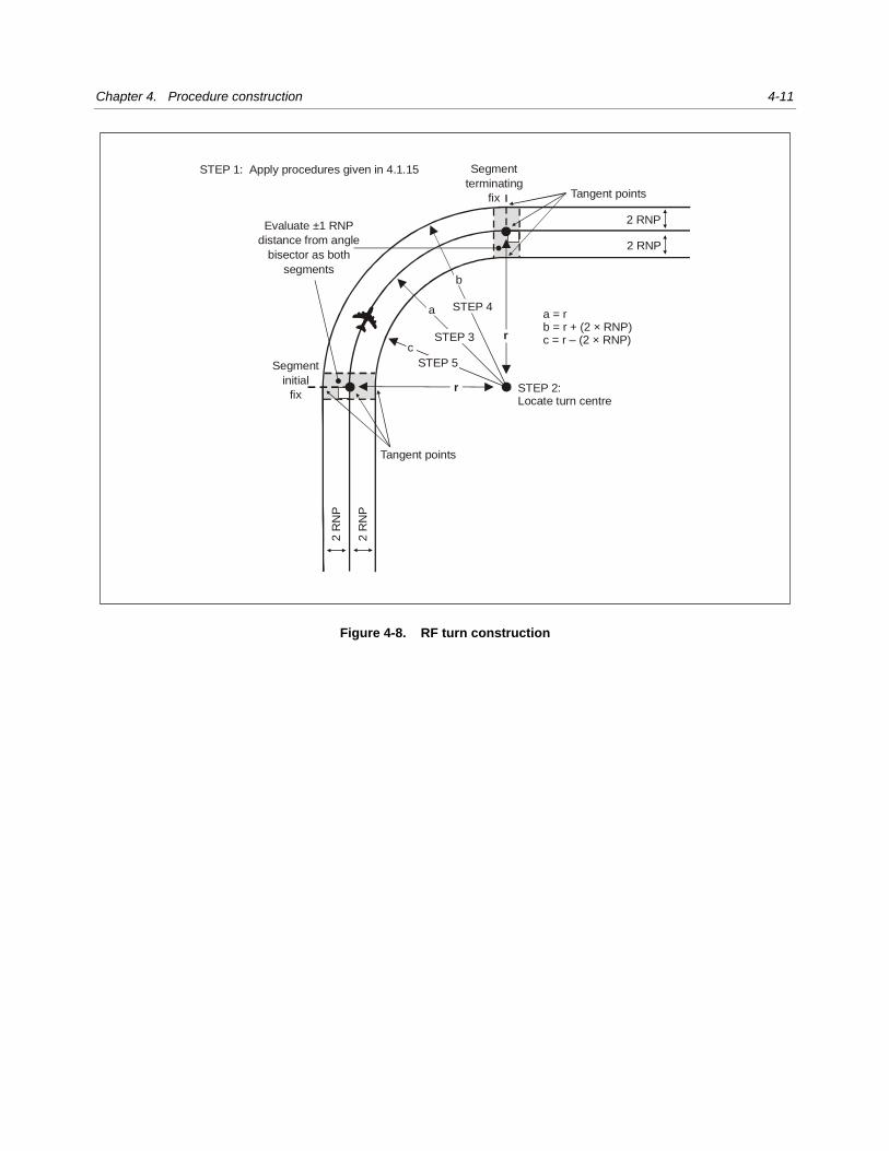
4.1.15 The turn area is bounded by concentric arcs. The minimum turn radius is 2 × RNP.
STEP 1: Determine the ground track necessary to avoid obstacles. Calculate the turn(s) and associated radii (r)
necessary to best achieve the ground track. Apply 3.2.8 to verify the bank angle associated with R is within the
Table 3-3 specified values.
STEP 2: Locate the turn centre at a perpendicular distance “r” from the inbound and outbound segments. This is the
common centre for the nominal turn track, outer boundary and inner boundary arcs.
STEP 3: Construct the flight path. Draw an arc of radius “r” from the tangent point on the inbound course to the
tangent point on the outbound track.
STEP 4: Construct the outer turn area boundary. Draw an arc of radius (r + 2 * RNP) from the tangent point on the
inbound segment outer boundary to the tangent point on the outbound track outer boundary.
STEP 5: Construct the inner turn area boundary. Draw an arc of radius (r – 2 * RNP) from the tangent point on the
inbound segment inner boundary to the tangent point on the inner boundary of the outbound track.
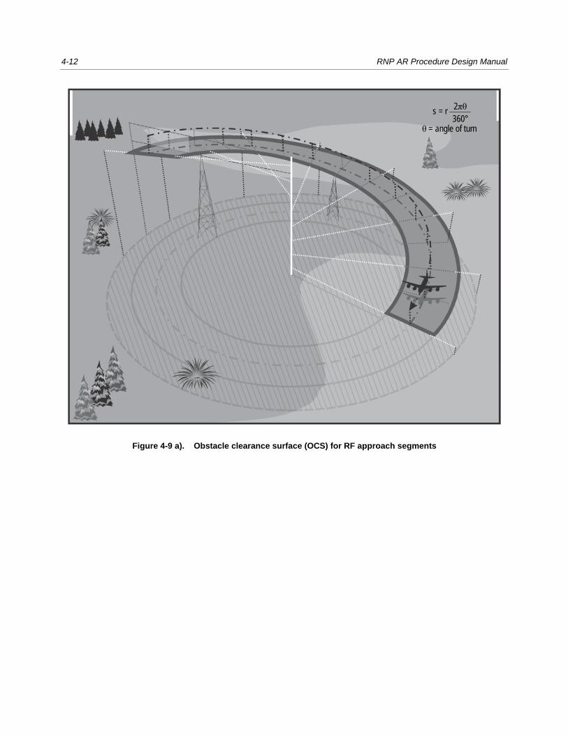
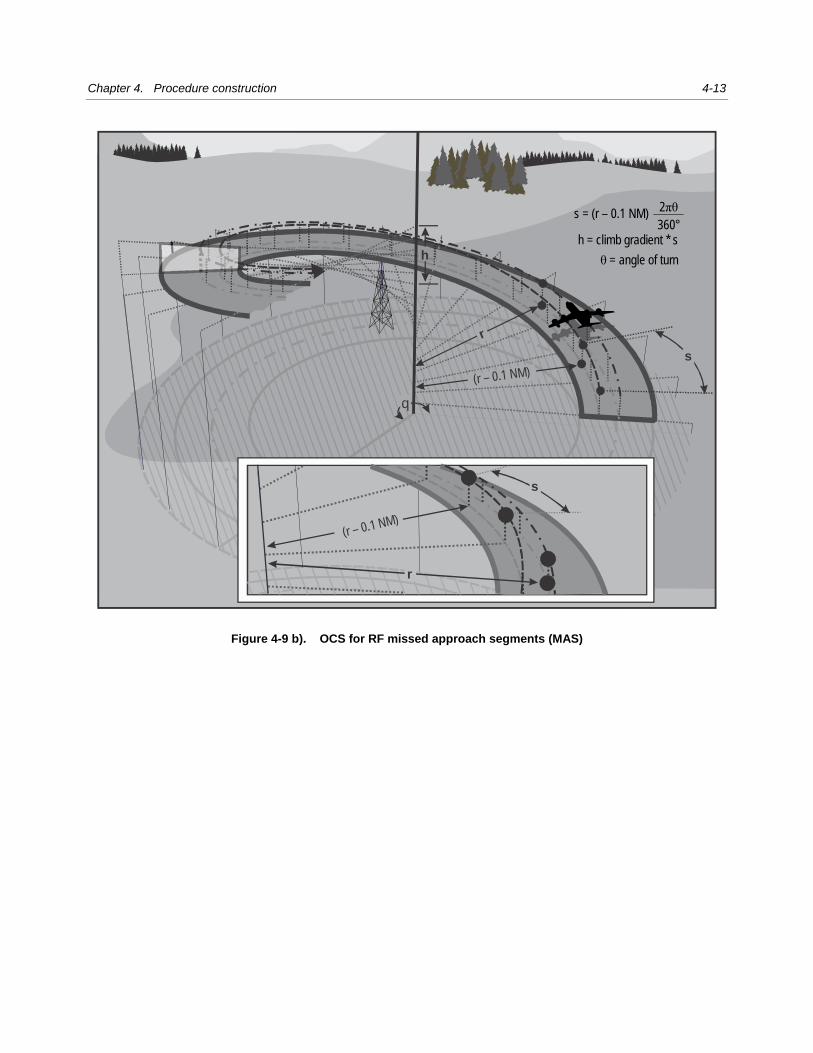
STEP 6: The height of the surface is constant along a radial line in a manner similar to a spiral staircase as
illustrated in Figure 4-9 a) for approach and Figure 4-9 b) for missed approach. To determine the height of the surface
for an RF leg in the approach, calculate the height based on the gradient along the nominal track and apply the height
across a radial line through the point. To determine the height of the surface for an RF leg in the missed approach, the
distance for the gradient is based on an arc length calculated using a radius of (r – 0.1 NM).
Calculation of descent gradients
4.1.16 Descent gradients are calculated between the nominal fix positions. For RF segments, the distance used is
the arc distance between the nominal fix positions.
Chapter 4. Procedure construction 4-11
Figure 4-8. RF turn construction
r
r
2 RNP
2 RNP
2 R
NP
2 R
NP
STEP 2:Locate turn centre
STEP 1: Apply procedures given in 4.1.15
Segment
initial
fix
a = rb = r + (2 × RNP)c = r – (2 × RNP)
Segment
terminating
fix
STEP 3
STEP 4
STEP 5
a
b
c
Tangent points
Tangent points
Evaluate ±1 RNP
distance from angle
bisector as both
segments
4-12 RNP AR Procedure Design Manual
Figure 4-9 a). Obstacle clearance surface (OCS) for RF approach segments
s = r 2πθ360°
θ = angle of turn
Chapter 4. Procedure construction 4-13
Figure 4-9 b). OCS for RF missed approach segments (MAS)
r
q
h
r
(r 1 N )– 0. M
(r 1 N )– 0. M
s
s
h = limb radientc g * s
s = (r – 0.1 NM) 2πθ360°
θ = angle of turn

4-14 RNP AR Procedure Design Manual
Mountainous terrain
4.1.17 In mountainous terrain, minimum obstacle clearance (MOC) for the initial and intermediate and missed
approach segments should be increased by as much as 100 per cent.
4.2 INITIAL APPROACH SEGMENT
RNP navigation accuracy requirement
4.2.1 In the initial approach segment the least stringent and the optimum RNP navigation accuracy requirement
is 1.0 NM. The most stringent is 0.1 NM.
Length
4.2.2 Segments should be designed with sufficient length to allow the required descent to be as close to the
optimum gradient as possible and to take account of DTA where fly-by turns are required.
4.2.3 Minimum straight segment (any segment) length is 2 × RNP (+DTA, as appropriate, for fly-by turn
construction). Paragraph 4.1.10 applies where the lateral accuracy value changes occur (changes 1 × RNP prior to the
fix).
4.2.4 The maximum initial segment length (total of all component segments) is 50 NM.
Alignment
4.2.5 The normal arrival for an RNP AR procedure will be via a direct RNP or RNAV route. However, RNP AR
procedures can also incorporate the normal RNP APCH T- or Y-bar arrangement. This is based on a runway-aligned
final segment preceded by an intermediate segment and up to three initial segments arranged either side of and along
the final approach track to form a T or a Y.
4.2.6 RNAV enables the geometry of approach procedure design to be very flexible. The “Y” configuration is
preferred where obstructions and air traffic flow allow. The approach design should provide the least complex
configuration possible to achieve the desired minimum OCA/H. See Figure 4-10 for examples.
4.2.7 Turns for connecting TF legs should normally be restricted to 90 degrees. For turns greater than this, RF
legs should be used and may be considered for all turns. For the T and Y configurations, offset initial approach fixes
(IAFs) are located such that a course change of 70 to 90 degrees is required at the IF. The capture region for tracks
inbound to the offset IAF extends 180 degrees about the IAFs, providing a direct entry when the course change at the
intermediate fix (IF) is 70 degrees or more.
Lateral initial segments 4.2.8 The lateral initial segments are based on course differences of 70 to 90 degrees from the intermediate
segment track. This arrangement ensures that entry from within a capture region requires a change of course at the IAF
not greater than 110 degrees.

Chapter 4. Procedure construction 4-15
Figure 4-10. Application of basic Y and basic T
Central initial segment 4.2.9 The central initial segment may commence at the IF. It is normally aligned with the intermediate segment.
Its capture region is 70 to 90 degrees either side of the initial segment track, the angle being identical to the course
change at the IF for the corresponding offset IAF. For turns greater than 110 degrees at the IAFs, sector 1 or 2 entries
should be used.
Restricted initial segments
4.2.10 Where one or both offset IAFs are not provided, a direct entry will not be available from all directions. In
such cases a holding pattern may be provided at the IAF to enable entry to the procedure via a procedure turn.
IAF IAF
IF
FAP

4-16 RNP AR Procedure Design Manual
4.3 HOLDING
4.3.1 If holding patterns are to be provided, the preferred configuration is located at the IAF and aligned with the
initial segment.
Descent gradient 4.3.2 See Table 4-2 for standard and maximum descent values.
Minimum altitudes
4.3.3 Minimum altitudes in the initial approach segment shall be established in 50-m or 100-ft increments, as
appropriate. The altitude selected shall provide an MOC of 300 m (984 ft) above obstacles and must not be lower than
any altitude specified for any portion of the intermediate or final approach segments.
Procedure altitudes/heights
4.3.4 All initial approach segments shall have procedure altitudes/heights established and published. Procedure
altitudes/heights shall not be less than the OCA/H and shall be developed in coordination with air traffic control (ATC),
taking into account the aircraft requirements. The initial segment procedure altitude/height should be established to allow
the aircraft to intercept the FAS descent gradient/angle from within the intermediate segment.
4.4 INTERMEDIATE APPROACH SEGMENT
4.4.1 The intermediate approach segment blends the initial approach segment into the FAS. It is the segment in
which aircraft configuration, speed and positioning adjustments are made for entry into the FAS.
Table 4-2. Descent gradient constraints
Segment Descent gradient
Standard Maximum
Arrival 4% (2.4°) 8% (4.7°)
Initial 4% (2.4°) 8% (4.7°)
Intermediate ≤2.5% (1.4°) Equal to final
segment gradient
Final 5.2% (3°) See Table 4-3

Chapter 4. Procedure construction 4-17
RNP navigation accuracy requirement
4.4.2 In the intermediate approach segment, the least stringent and the optimum RNP navigation accuracy
requirement is 1.0 NM. The most stringent is 0.1 NM.
Length
4.4.3 Segments should be designed with sufficient length to allow the required descent to be as close to the
OPTIMUM gradient as possible and accommodate the DTA where fly-by turns are required. Minimum straight segment
(any segment) length is: 2 × RNP (+DTA, as appropriate, for fly-by turn constructions). Paragraph 4.1.10 applies where
the lateral accuracy value changes occur (RNP value changes 1 RNP prior to fix).
Alignment
4.4.4 The intermediate approach segment should be aligned with the FAS whenever possible. Fly-by turns at the
final approach point (FAP) are limited to a maximum of 15-degree track change at the fix. Turns of more than 15
degrees should employ an RF leg.
Descent gradient
4.4.5 The optimum descent gradient in the intermediate segment is 2.5 per cent (1.4 degrees). The maximum
descent gradient is the same as the maximum final approach gradient. If a descent angle higher than standard is used,
the evaluation should ensure that sufficient flexibility is provided for the continuous descent approach (CDA) technique.
4.4.6 If a higher than standard gradient is required, a prior segment must make provision for the aircraft to
configure for final segment descent.
4.4.7 Where a track change using a fly-by turn occurs at the FAP, the reduction in track distance may be ignored
as the difference is negligible (maximum 15-degree turn).
Table 4-3. Maximum VPA
Aircraft Category VPA θ Gradient % Ft/NM
A < 150 km/h (80 kt) 6.4 11.2 682
150 km/h ≤ A < 167 km/h
(80 kt ≤ A < 90 kt) 5.7 9.9 606
B 4.2 7.3 446
C 3.6 6.3 382
D 3.1 5.4 329
4-18 RNP AR Procedure Design Manual
Minimum altitude/height
4.4.8 The minimum altitude/height is the height of the highest obstacle within the intermediate approach
segment area plus the MOC of 150 m (492 ft).
4.4.9 The minimum altitude/height in the intermediate approach segment shall be established in 50-m or 100-ft
increments, as appropriate.
Procedure altitudes/heights
4.4.10 Procedure altitudes/heights in the intermediate segment shall be established to allow the aircraft to
intercept a prescribed final approach descent.
Minimum obstacle clearance (MOC)
4.4.11 When establishing the intermediate segment minimum altitude (vertical path angle (VPA) intercept altitude),
the difference between the 150 m (492 ft) intermediate MOC value and the MOC value provided by the VEB OAS where
it reaches the height of the intermediate segment controlling obstruction should be considered.
4.4.12 If the VEB MOC at the height of the controlling obstruction exceeds the intermediate segment MOC, then
the VEB MOC value should be applied (see Figure 4-11).
4.4.13 If the VEB is less than the MOC for the intermediate segment at the FAP, the intermediate MOC should be
extended into the final segment until intersecting the VEB surface (see Figure 4-12).
Note.— If the minimum altitude has to be raised because of obstacles in the intermediate segment, the FAP must be moved. The VEB must be recalculated and a new minimum altitude derived.
4.5 FAS
4.5.1 FAS lateral guidance is based on RNP. Vertical guidance is based on BARO-VNAV avionics. The FAS
OAS (VEB) is based on limiting the vertical error performance of BARO-VNAV avionic systems to stated limits.
RNP navigation accuracy requirement
4.5.2 In the FAS, the least stringent RNP navigation accuracy requirement is 0.5 NM, the optimum RNP
navigation accuracy requirement is 0.3 NM and the most stringent RNP navigation accuracy requirement is 0.1 NM. A
more stringent than optimum RNP navigation accuracy requirement should only be used if:
a) 0.3 NM results in a DA/H greater than 90 m (295 ft) above the elevation of the LTP; and
b) a significant operational advantage can be obtained.
4.5.3 In these cases, the most stringent navigation accuracy requirement that may be used is 0.1 NM. Where
approaches with RNP navigation accuracy requirements less than 0.3 are published, OCA/H should also be published
for an RNP navigation accuracy requirement of 0.3 NM.

Chapter 4. Procedure construction 4-19
Figure 4-11. Intermediate segment MOC 1
Figure 4-12. Intermediate segment MOC 2
OAS
VPA
FAP
based on
VEB MOC
FAP
based on
150 m (492 ft)
MOC
VEB MOC
LTP
Tangent
plane
FAP Intermediate segment
DVEB
150 m (492 ft) MOC
OCS intermediate
VPA ( )θ
OASVEB
4-20 RNP AR Procedure Design Manual
Length
4.5.4 No maximum or minimum is specified. However, the length must accommodate the descent required and
must provide a stabilized segment prior to OCA/H.
Alignment
Straight-in approaches
4.5.5 The optimum final approach alignment is a TF segment straight in from FAP to LTP on the extended
runway centreline (see Figure 4-13). If necessary, the TF track may be offset by up to five degrees. Where the track is
offset, it must cross the extended runway centreline at least 450 m (1 476 ft) before the LTP.
Location of FAP
4.5.6 The FAP is a point on the reciprocal of the true final approach course where the VPA extending from RDH
above the LTP (fictitious threshold point (FTP) if offset) intersects the intermediate segment altitude.
Figure 4-13. FAP to LTP distance
FAPIntermediate segment altitude
VPA

Chapter 4. Procedure construction 4-21
4.5.7 In all cases, the FAP shall be identified as a named fix. The latitude and longitude of the FAP is calculated
geodetically from the LTP/FTP using:
a) the reciprocal of the true track of the final approach TF leg (true track – 180 degrees); and
b) the required distance from LTP (FTP if offset) to the FAP.
Calculation of FAP-LTP distance
4.5.8 The FAP to LTP distance can be calculated as follows:
( )
ee
e
r + ar * ln
r +b +RDHd =
tan VPA
or
d = re * ln[(re + a)/(re + b + RDH)]/tan(VPA)
where
d = FAP to LTP distance (m or ft, as appropriate)
re = (mean earth radius) 6367435.67964 (m) or 20 890 537 (ft), as appropriate
RDH = reference datum height (m or ft, as appropriate)
a = FAP altitude (m or ft, as appropriate)
b = LTP elevation (m or ft, as appropriate)
The calculations are geoidal (rather than ellipsoidal) since the VPA is a pressure gradient determined by the barometric
altimeter and is therefore relative to the geoid. The VPA maintains a gradient relative to the earth and follows an arcing
path as illustrated in Figure 4-13.
Turns in the FAS
4.5.9 A final segment may be designed using an RF leg segment when obstacles or operational requirements
prevent a straight-in approach from the FAP to the LTP. Fly-by turns are not allowed. The along-track geodetic distance
from the LTP (FTP if offset) to the point the GP intercepts the intermediate segment minimum altitude (DFAP) should be
determined and DFAP calculated.
4.5.10 The leg (TF or RF) on which the FAP is located is determined by comparing this distance with the total
length of the FAS.
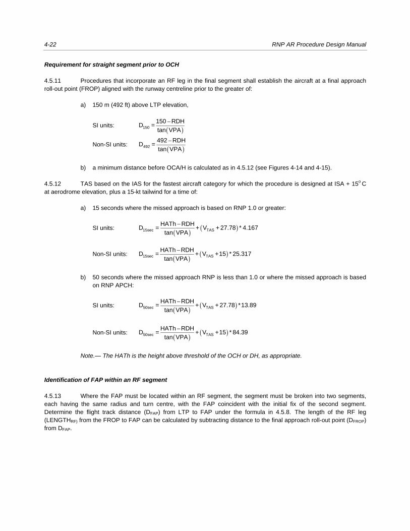
4-22 RNP AR Procedure Design Manual
Requirement for straight segment prior to OCH
4.5.11 Procedures that incorporate an RF leg in the final segment shall establish the aircraft at a final approach
roll-out point (FROP) aligned with the runway centreline prior to the greater of:
a) 150 m (492 ft) above LTP elevation,
SI units: ( )−
150
150 RDHD =
tan VPA
Non-SI units: ( )−
492
492 RDHD =
tan VPA
b) a minimum distance before OCA/H is calculated as in 4.5.12 (see Figures 4-14 and 4-15).
4.5.12 TAS based on the IAS for the fastest aircraft category for which the procedure is designed at ISA + 15o
C
at aerodrome elevation, plus a 15-kt tailwind for a time of:
a) 15 seconds where the missed approach is based on RNP 1.0 or greater:
SI units: ( ) ( )−15sec TAS
HATh RDHD = + V + 27.78 * 4.167
tan VPA
Non-SI units: ( ) ( )−15sec TAS
HATh RDHD = + V +15 * 25.317
tan VPA
b) 50 seconds where the missed approach RNP is less than 1.0 or where the missed approach is based
on RNP APCH:
SI units: ( ) ( )−50sec TAS
HATh RDHD = + V + 27.78 *13.89
tan VPA
Non-SI units: ( ) ( )−50sec TAS
HATh RDHD = + V +15 * 84.39
tan VPA
Note.— The HATh is the height above threshold of the OCH or DH, as appropriate.
Identification of FAP within an RF segment
4.5.13 Where the FAP must be located within an RF segment, the segment must be broken into two segments,
each having the same radius and turn centre, with the FAP coincident with the initial fix of the second segment.
Determine the flight track distance (DFAP) from LTP to FAP under the formula in 4.5.8. The length of the RF leg
(LENGTHRF) from the FROP to FAP can be calculated by subtracting distance to the final approach roll-out point (DFROP)
from DFAP.

Chapter 4. Procedure construction 4-23
Figure 4-14. FROP
Figure 4-15. Constraints on OCH and FROP
Roll-out point
on final
centreline track
LTP
(OCH – RDH)/tan VPA
FROP based on the highest of OCH 1, OCH 2, OCH 3
150 m(492 ft)
RDH
LTP to OCH 1 distance 15 or 50 seconds
OCH 1 due obstaclesto
OCH 2 due to minimumheight constraint
OCH 3 due to stabilizationtime requirement
FROP
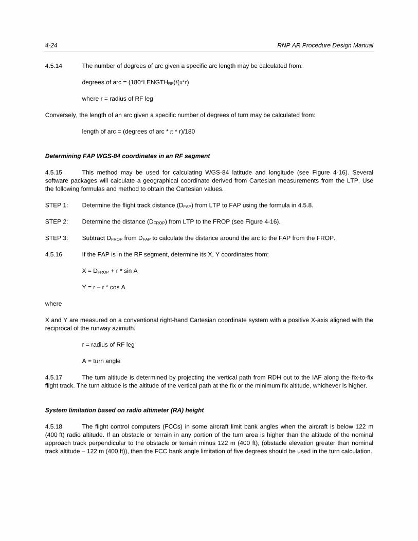
4-24 RNP AR Procedure Design Manual
4.5.14 The number of degrees of arc given a specific arc length may be calculated from:
degrees of arc = (180*LENGTHRF)/(π*r)
where r = radius of RF leg
Conversely, the length of an arc given a specific number of degrees of turn may be calculated from:
length of arc = (degrees of arc * π * r)/180
Determining FAP WGS-84 coordinates in an RF segment
4.5.15 This method may be used for calculating WGS-84 latitude and longitude (see Figure 4-16). Several
software packages will calculate a geographical coordinate derived from Cartesian measurements from the LTP. Use
the following formulas and method to obtain the Cartesian values.
STEP 1: Determine the flight track distance (DFAP) from LTP to FAP using the formula in 4.5.8.
STEP 2: Determine the distance (DFROP) from LTP to the FROP (see Figure 4-16).
STEP 3: Subtract DFROP from DFAP to calculate the distance around the arc to the FAP from the FROP.
4.5.16 If the FAP is in the RF segment, determine its X, Y coordinates from:
X = DFROP + r * sin A
Y = r – r * cos A
where
X and Y are measured on a conventional right-hand Cartesian coordinate system with a positive X-axis aligned with the
reciprocal of the runway azimuth.
r = radius of RF leg
A = turn angle
4.5.17 The turn altitude is determined by projecting the vertical path from RDH out to the IAF along the fix-to-fix
flight track. The turn altitude is the altitude of the vertical path at the fix or the minimum fix altitude, whichever is higher.
System limitation based on radio altimeter (RA) height
4.5.18 The flight control computers (FCCs) in some aircraft limit bank angles when the aircraft is below 122 m
(400 ft) radio altitude. If an obstacle or terrain in any portion of the turn area is higher than the altitude of the nominal
approach track perpendicular to the obstacle or terrain minus 122 m (400 ft), (obstacle elevation greater than nominal
track altitude – 122 m (400 ft)), then the FCC bank angle limitation of five degrees should be used in the turn calculation.
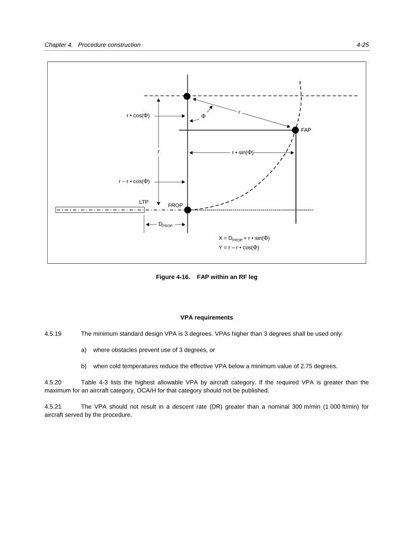
Chapter 4. Procedure construction 4-25
Figure 4-16. FAP within an RF leg
VPA requirements
4.5.19 The minimum standard design VPA is 3 degrees. VPAs higher than 3 degrees shall be used only:
a) where obstacles prevent use of 3 degrees, or
b) when cold temperatures reduce the effective VPA below a minimum value of 2.75 degrees.
4.5.20 Table 4-3 lists the highest allowable VPA by aircraft category. If the required VPA is greater than the
maximum for an aircraft category, OCA/H for that category should not be published.
4.5.21 The VPA should not result in a descent rate (DR) greater than a nominal 300 m/min (1 000 ft/min) for
aircraft served by the procedure.
LTPFROP
FAP
DFROP
Φ
r
rr • cos( )Φ
r – r • cos( )Φ
r • sin( )Φ
X = D + FROP
Y = r – r • cos( )
r • sin( )ΦΦ
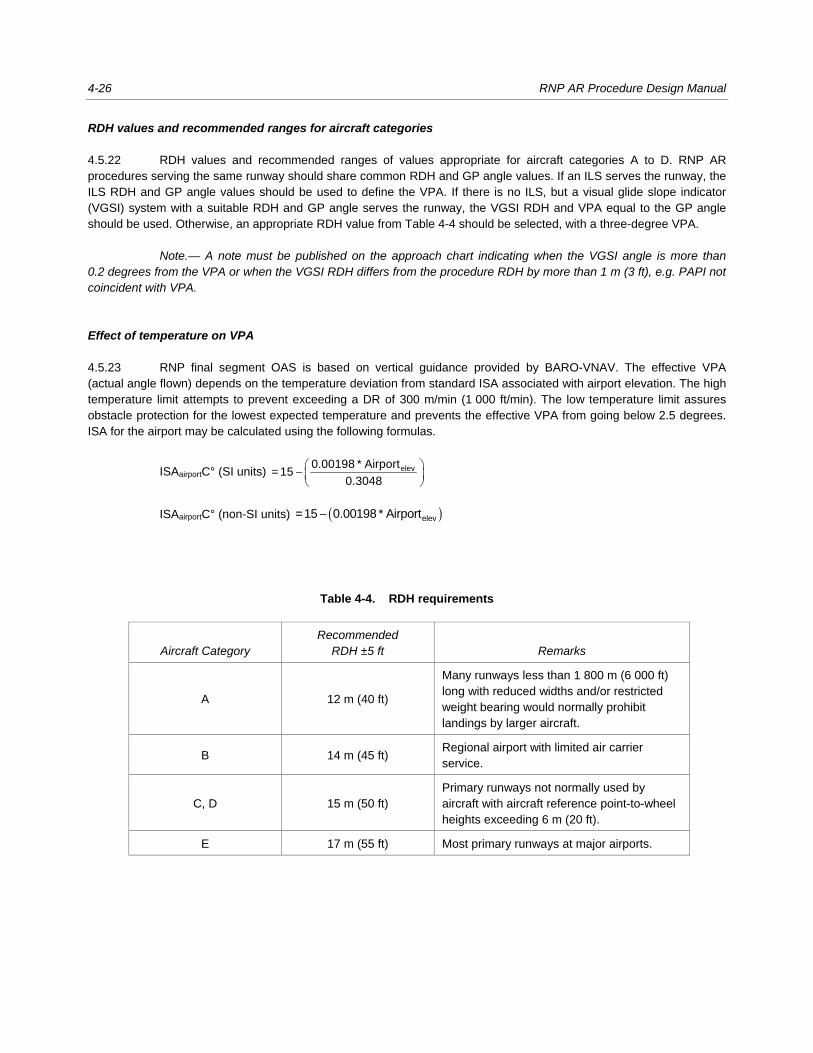
4-26 RNP AR Procedure Design Manual
RDH values and recommended ranges for aircraft categories
4.5.22 RDH values and recommended ranges of values appropriate for aircraft categories A to D. RNP AR
procedures serving the same runway should share common RDH and GP angle values. If an ILS serves the runway, the
ILS RDH and GP angle values should be used to define the VPA. If there is no ILS, but a visual glide slope indicator
(VGSI) system with a suitable RDH and GP angle serves the runway, the VGSI RDH and VPA equal to the GP angle
should be used. Otherwise, an appropriate RDH value from Table 4-4 should be selected, with a three-degree VPA.
Note.— A note must be published on the approach chart indicating when the VGSI angle is more than 0.2 degrees from the VPA or when the VGSI RDH differs from the procedure RDH by more than 1 m (3 ft), e.g. PAPI not coincident with VPA.
Effect of temperature on VPA
4.5.23 RNP final segment OAS is based on vertical guidance provided by BARO-VNAV. The effective VPA
(actual angle flown) depends on the temperature deviation from standard ISA associated with airport elevation. The high
temperature limit attempts to prevent exceeding a DR of 300 m/min (1 000 ft/min). The low temperature limit assures
obstacle protection for the lowest expected temperature and prevents the effective VPA from going below 2.5 degrees.
ISA for the airport may be calculated using the following formulas.
ISAairportC° (SI units) −
elev0.00198 * Airport= 15
0.3048
ISAairportC° (non-SI units) ( )− elev=15 0.00198 * Airport
Table 4-4. RDH requirements
Aircraft Category Recommended
RDH ±5 ft Remarks
A 12 m (40 ft)
Many runways less than 1 800 m (6 000 ft)
long with reduced widths and/or restricted
weight bearing would normally prohibit
landings by larger aircraft.
B 14 m (45 ft) Regional airport with limited air carrier
service.
C, D 15 m (50 ft)
Primary runways not normally used by
aircraft with aircraft reference point-to-wheel
heights exceeding 6 m (20 ft).
E 17 m (55 ft) Most primary runways at major airports.
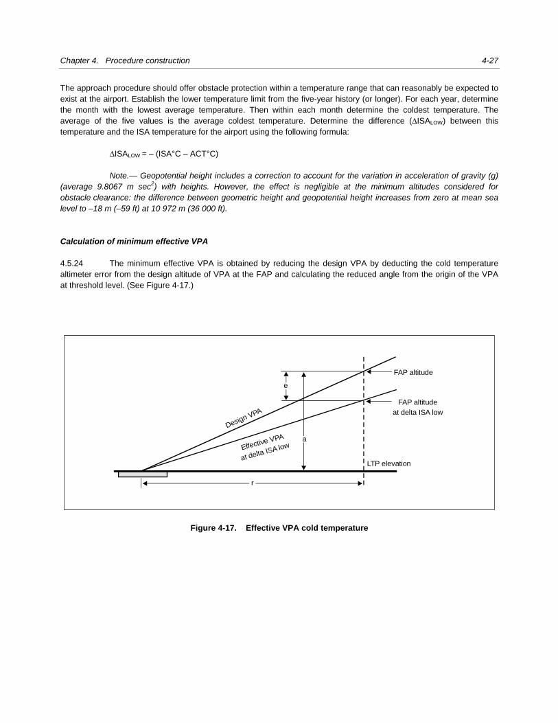
Chapter 4. Procedure construction 4-27
The approach procedure should offer obstacle protection within a temperature range that can reasonably be expected to
exist at the airport. Establish the lower temperature limit from the five-year history (or longer). For each year, determine
the month with the lowest average temperature. Then within each month determine the coldest temperature. The
average of the five values is the average coldest temperature. Determine the difference (ΔISALOW) between this
temperature and the ISA temperature for the airport using the following formula:
ΔISALOW = – (ISA°C – ACT°C)
Note.— Geopotential height includes a correction to account for the variation in acceleration of gravity (g) (average 9.8067 m sec2) with heights. However, the effect is negligible at the minimum altitudes considered for obstacle clearance: the difference between geometric height and geopotential height increases from zero at mean sea level to –18 m (–59 ft) at 10 972 m (36 000 ft). Calculation of minimum effective VPA 4.5.24 The minimum effective VPA is obtained by reducing the design VPA by deducting the cold temperature
altimeter error from the design altitude of VPA at the FAP and calculating the reduced angle from the origin of the VPA
at threshold level. (See Figure 4-17.)
Figure 4-17. Effective VPA cold temperature
e
a
FAP altitude
LTP elevation
FAP altitude
at delta ISA low
Effective VPA
at delta ISA low
r
Design VPA
4-28 RNP AR Procedure Design Manual
Low temperature limit
4.5.25 The effective VPA at the minimum promulgated temperature must not be less than 2.5 degrees. The
nominal VPA, in some cases may be raised above 3.0 degrees. However, consideration must be given to: aircraft
performance at the higher VPA; high temperature effects; and the regulatory constraints on the maximum GP for the
aircraft.
4.5.25.1 If the temperature history for the location indicates the low temperature limitation is frequently encountered
during established busy recovery times, consideration should be given to raising the GP angle to the lowest angle (within
the limits of Table 4-3) that will make the approach more frequently usable.
4.5.25.1.1 The minimum VPA is the larger of 2.5 degrees, or
VPA =
a + eMin arctan( )
r where a = FAP altitude – LTP elevation (m or ft, as appropriate)
e (Si units) = ΔISALOW * [(0.19 * 0.3048) + (0.0038 * a)] + (0.032 * a) + (4.9 * 0.3048), or
e (non-Si units) = ΔISALOW * [0.19 + (0.0038 * a)] + (0.032 * a) + 4.9
r = ( )a
tan VPA
4.5.25.1.2 If the effective VPA is less than 2.5 degrees, calculate the ΔISALOW to achieve an angle of 2.5 degrees using one of the following formulas:
ΔISALOW (SI units) = el (0.032 * a) (4.9 * 0.3048)
(0.19 * 0.3048) + (0.0038 * a)
− − −
ΔISALOW (non-SI units) = − − −
+el (0.032 * a) 4.9
0.19 (0.0038*a)
where
el = FAP altitude – b
b = r * tan(2.5°) + LTP elevation
a
r =tan(VPA)
a = FAP altitude – LTP elevation (m or ft, as appropriate)

Chapter 4. Procedure construction 4-29
4.5.25.1.3 Determine the published low temperature limitation “NA below” for the procedure using the ΔISALOW
derived from the equation in 4.5.25.1.2 in the following formula:
NA below = ISA + ΔISALOW
Note.— If the temperature history for the location indicates the low temperature limitation is frequently encountered during established busy recovery times, consider raising the VPA to the lowest angle that will make the approach usable more often. Calculation of maximum effective VPA 4.5.26 The maximum effective VPA is obtained by increasing the design VPA by adding the high temperature
altimeter error to the design altitude of VPA at the FAP and calculating the increased angle from the origin of the VPA at
threshold level (see Figure 4-18).
Figure 4-18. Effective VPA hot temperature
eh
ac
FAP altitude at
delta ISA high
LTP elevation
FAP altitude
r
Maximum VPA
Design VPA
4-30 RNP AR Procedure Design Manual
4.5.26.1 To accomplish this, determine the maximum ΔISAHigh (above ISA) that will produce the maximum allowed
VPA using one of the following formulas:
ΔISAHigh (SI units) =− −eh (0.032 * a) (4.9 * 0.3048)
(0.19 * 0.3048) + (0.0038 * a)
ΔISAHigh (non-SI units) =− −eh (0.032 * a) 4.9
0.19 + (0.0038 * a)
where
eh = c – FAP altitude
c = r * tan (α) + LTP elevation
α = maximum allowed VPA
a = FAP altitude – LTP elevation
a
r =tan(VPA)
4.5.26.2 The maximum effective VPA angle is 1.13 times the Table 4-3 maximum design value for the fastest
published approach category. If the calculated effective VPA exceeds this, then the published maximum temperature
must be restricted to a lower value. Determine NAabove with the following formula:
NAabove = ISA airport + ΔISAHigh
VEB
4.5.27 Calculation of the VEB is described in Appendices 1 and 2.
Final approach OAS
4.5.28 The distance of the final approach OAS origin from LTP (DVEB) and its slope are defined by the VEB.
Note.— In case of RNP navigation accuracy requirement reduction in segments where the VEB is applied, the least stringent RNP navigation accuracy requirement shall be used in VEB calculation.
4.5.29 The height of the OAS at any distance “x” from the LTP can be calculated as follows:
( ) − −fHGT e eOAS = r +LTP e r LTP
where
( )−
= gradientVEB
e
* OASx Df
r

Chapter 4. Procedure construction 4-31
OASHGT = height of the VEB OAS (m or ft, as appropriate)
x = distance from LTP to obstacle (m or ft, as appropriate)
DVEB = distance from LTP to the LTP level intercept of the VEB OAS (m or ft, as appropriate)
re = (mean earth radius) 6367435.67964 (m) or 20 890 537 (ft), as appropriate
OASgradient = value as derived from Appendix 1 or 2, as appropriate
Note.— DVEB and tan final approach OAS are both obtained from Appendix 1 (SI units) or Appendix 2 (non-SI units).
Adjustment for aircraft body geometry (bg)
4.5.30 Where the final approach is a straight segment, the OAS gradient is the same for the straight and curved
path portions. However, the obstacle clearance margin is increased to account for the difference in the flight paths of the
navigation reference point on the aircraft and the wheels. For wings level, this is assumed to be 8 m (25 ft) for all aircraft.
Additional adjustment for bg during a bank is calculated as follows:
bg = 40 * sin(bank angle) m; or
bg = 132 * sin(bank angle) ft
The optimum bank angle equals 18 degrees; however, other bank angles may be applied for specific aircraft. The
adjustment obstacle clearance margin for the curved section of the final approach and the relative orientation of the VEB
OAS for the straight and curved sections are illustrated in Figure 4-19.
Figure 4-19. OAS adjustment for TF and RF legs
VPA
TF OAS
TF OAS
RF OAS
TF OASorigin
RF OASorigin
RFFROP
RFsegmentinitial fix
1 RNP
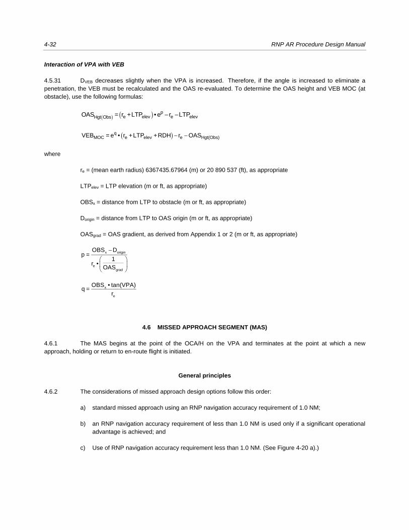
4-32 RNP AR Procedure Design Manual
Interaction of VPA with VEB
4.5.31 DVEB decreases slightly when the VPA is increased. Therefore, if the angle is increased to eliminate a
penetration, the VEB must be recalculated and the OAS re-evaluated. To determine the OAS height and VEB MOC (at
obstacle), use the following formulas:
( ) ( ) − −pe elev e elevHgt ObsOAS = r +LTP • e r LTP
( ) − −qMOC e elev e Hgt(Obs)VEB = e • r +LTP +RDH r OAS
where
re = (mean earth radius) 6367435.67964 (m) or 20 890 537 (ft), as appropriate
LTPelev = LTP elevation (m or ft, as appropriate)
OBSx = distance from LTP to obstacle (m or ft, as appropriate)
Dorigin = distance from LTP to OAS origin (m or ft, as appropriate)
OASgrad = OAS gradient, as derived from Appendix 1 or 2 (m or ft, as appropriate)
−
x origin
egrad
OBS Dp =
1r •
OAS
x
e
OBS • tan(VPA)q =
r
4.6 MISSED APPROACH SEGMENT (MAS)
4.6.1 The MAS begins at the point of the OCA/H on the VPA and terminates at the point at which a new
approach, holding or return to en-route flight is initiated.
General principles
4.6.2 The considerations of missed approach design options follow this order:
a) standard missed approach using an RNP navigation accuracy requirement of 1.0 NM;
b) an RNP navigation accuracy requirement of less than 1.0 NM is used only if a significant operational
advantage is achieved; and
c) Use of RNP navigation accuracy requirement less than 1.0 NM. (See Figure 4-20 a).)
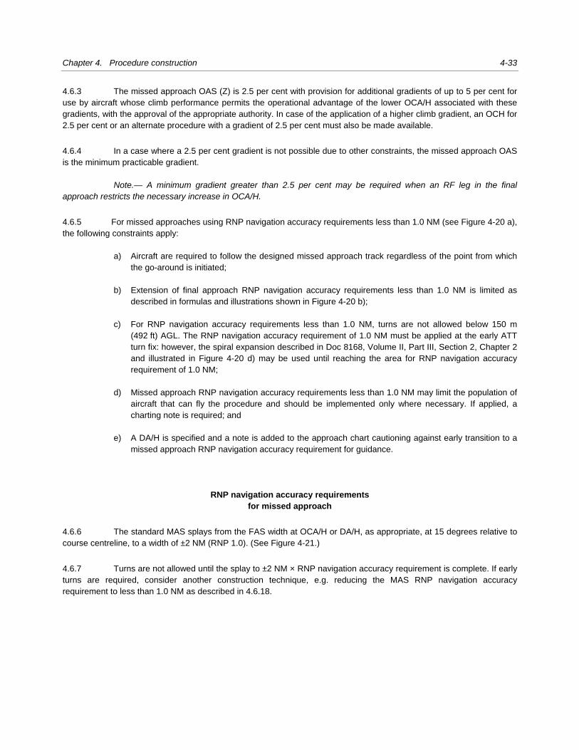
Chapter 4. Procedure construction 4-33
4.6.3 The missed approach OAS (Z) is 2.5 per cent with provision for additional gradients of up to 5 per cent for
use by aircraft whose climb performance permits the operational advantage of the lower OCA/H associated with these
gradients, with the approval of the appropriate authority. In case of the application of a higher climb gradient, an OCH for
2.5 per cent or an alternate procedure with a gradient of 2.5 per cent must also be made available.
4.6.4 In a case where a 2.5 per cent gradient is not possible due to other constraints, the missed approach OAS
is the minimum practicable gradient.
Note.— A minimum gradient greater than 2.5 per cent may be required when an RF leg in the final approach restricts the necessary increase in OCA/H.
4.6.5 For missed approaches using RNP navigation accuracy requirements less than 1.0 NM (see Figure 4-20 a),
the following constraints apply:
a) Aircraft are required to follow the designed missed approach track regardless of the point from which
the go-around is initiated;
b) Extension of final approach RNP navigation accuracy requirements less than 1.0 NM is limited as
described in formulas and illustrations shown in Figure 4-20 b);
c) For RNP navigation accuracy requirements less than 1.0 NM, turns are not allowed below 150 m
(492 ft) AGL. The RNP navigation accuracy requirement of 1.0 NM must be applied at the early ATT
turn fix: however, the spiral expansion described in Doc 8168, Volume II, Part III, Section 2, Chapter 2
and illustrated in Figure 4-20 d) may be used until reaching the area for RNP navigation accuracy
requirement of 1.0 NM;
d) Missed approach RNP navigation accuracy requirements less than 1.0 NM may limit the population of
aircraft that can fly the procedure and should be implemented only where necessary. If applied, a
charting note is required; and
e) A DA/H is specified and a note is added to the approach chart cautioning against early transition to a
missed approach RNP navigation accuracy requirement for guidance.
RNP navigation accuracy requirements for missed approach
4.6.6 The standard MAS splays from the FAS width at OCA/H or DA/H, as appropriate, at 15 degrees relative to
course centreline, to a width of ±2 NM (RNP 1.0). (See Figure 4-21.)
4.6.7 Turns are not allowed until the splay to ±2 NM × RNP navigation accuracy requirement is complete. If early
turns are required, consider another construction technique, e.g. reducing the MAS RNP navigation accuracy
requirement to less than 1.0 NM as described in 4.6.18.
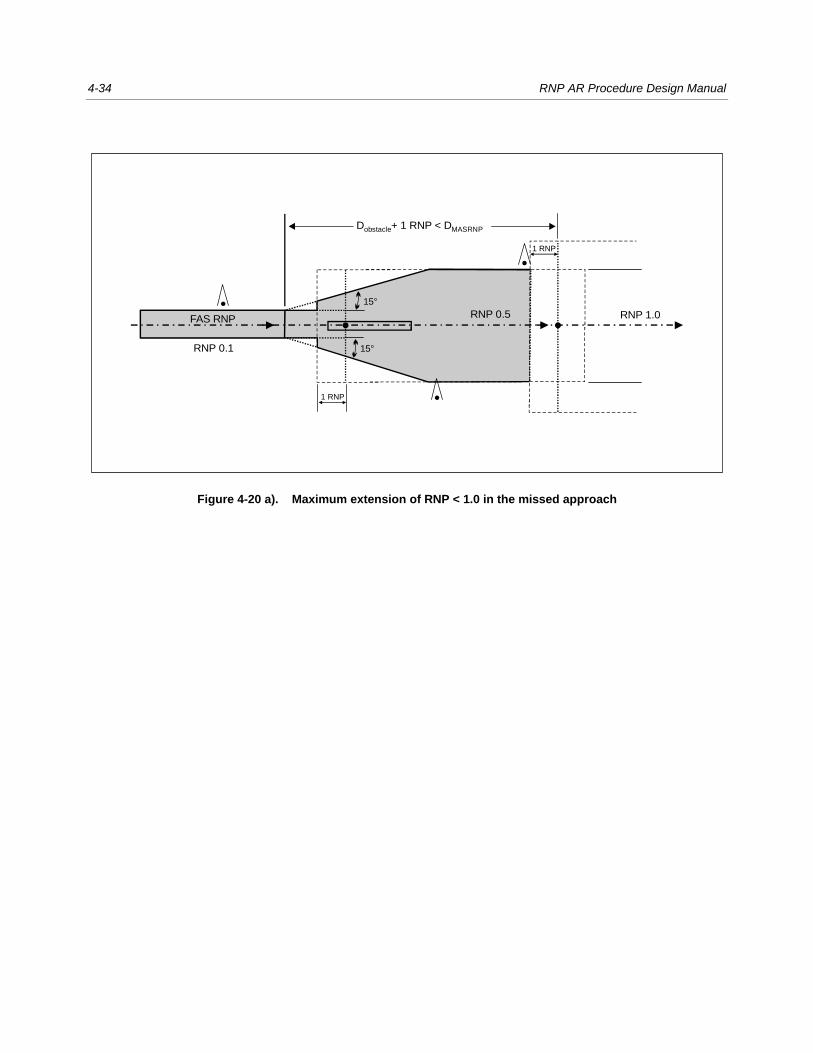
4-34 RNP AR Procedure Design Manual
Figure 4-20 a). Maximum extension of RNP < 1.0 in the missed approach
D + 1 RNP < Dobstacle MASRNP
RNP 1.0RNP 0.5
RNP 0.1
FAS RNP
1 RNP
1 RNP
15°
15°
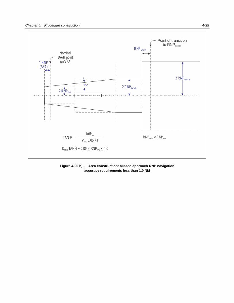
Chapter 4. Procedure construction 4-35
Figure 4-20 b). Area construction: Missed approach RNP navigation accuracy requirements less than 1.0 NM
15°
NominalDA/H point
on VPA
Point of transitionto RNPMAS(2)
RNPMAS(1)
1 RNP(FAS)
TAN = Drift IRU
V 0.05 KT TAS
RNP RNP MAS FAS<
2 RNPFAS
2 RNPMAS(2)
2 RNPMAS(1)
θ
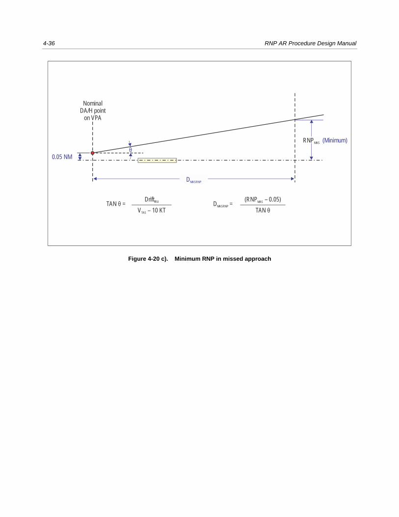
4-36 RNP AR Procedure Design Manual
Figure 4-20 c). Minimum RNP in missed approach
0.05 NMθ
(Minimum)
NominalDA/H point
on VPA
RNPMAS
DMASRNP
D = MASRNP
(RNP – 0.05) MAS
TAN θTAN = θ
Drift IRU
V – 10 KT TAS

Chapter 4. Procedure construction 4-37
Figure 4-20 d). Application of the spiral expansion
NominalDA/H point
on VPA
Point of transitionto RNPMAS(2)
2 RNPMAS(1)
RNPMAS(1)
2 RNPFAS
1 RNP(FAS)
15°
15°
c
2 RNPMAS(2)

4-38 RNP AR Procedure Design Manual
Figure 4-21. Missed approach splay
FAS RNP RNP 1.0
15°
15°
DSPLAY
2 NM
2 NM
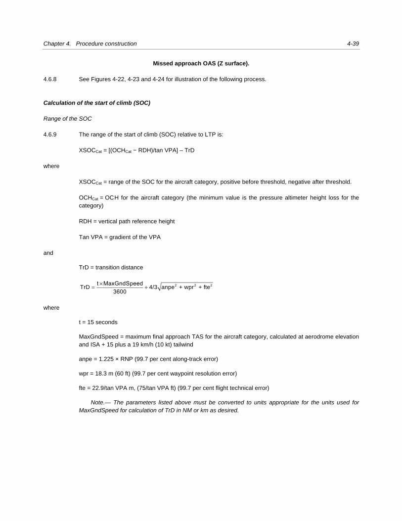
Chapter 4. Procedure construction 4-39
Missed approach OAS (Z surface). 4.6.8 See Figures 4-22, 4-23 and 4-24 for illustration of the following process.
Calculation of the start of climb (SOC)
Range of the SOC
4.6.9 The range of the start of climb (SOC) relative to LTP is:
XSOCCat = [(OCHCat − RDH)/tan VPA] – TrD
where
XSOCCat = range of the SOC for the aircraft category, positive before threshold, negative after threshold.
OCHCat = OC H for the aircraft category (the minimum value is the pressure altimeter height loss for the
category)
RDH = vertical path reference height
Tan VPA = gradient of the VPA
and
TrD = transition distance
×= + 2 2 2TrD 4/3 anpe + wpr + ftet MaxGndSpeed
3600
where t = 15 seconds MaxGndSpeed = maximum final approach TAS for the aircraft category, calculated at aerodrome elevation
and ISA + 15 plus a 19 km/h (10 kt) tailwind anpe = 1.225 × RNP (99.7 per cent along-track error) wpr = 18.3 m (60 ft) (99.7 per cent waypoint resolution error)
fte = 22.9/tan VPA m, (75/tan VPA ft) (99.7 per cent flight technical error)
Note.— The parameters listed above must be converted to units appropriate for the units used for MaxGndSpeed for calculation of TrD in NM or km as desired.
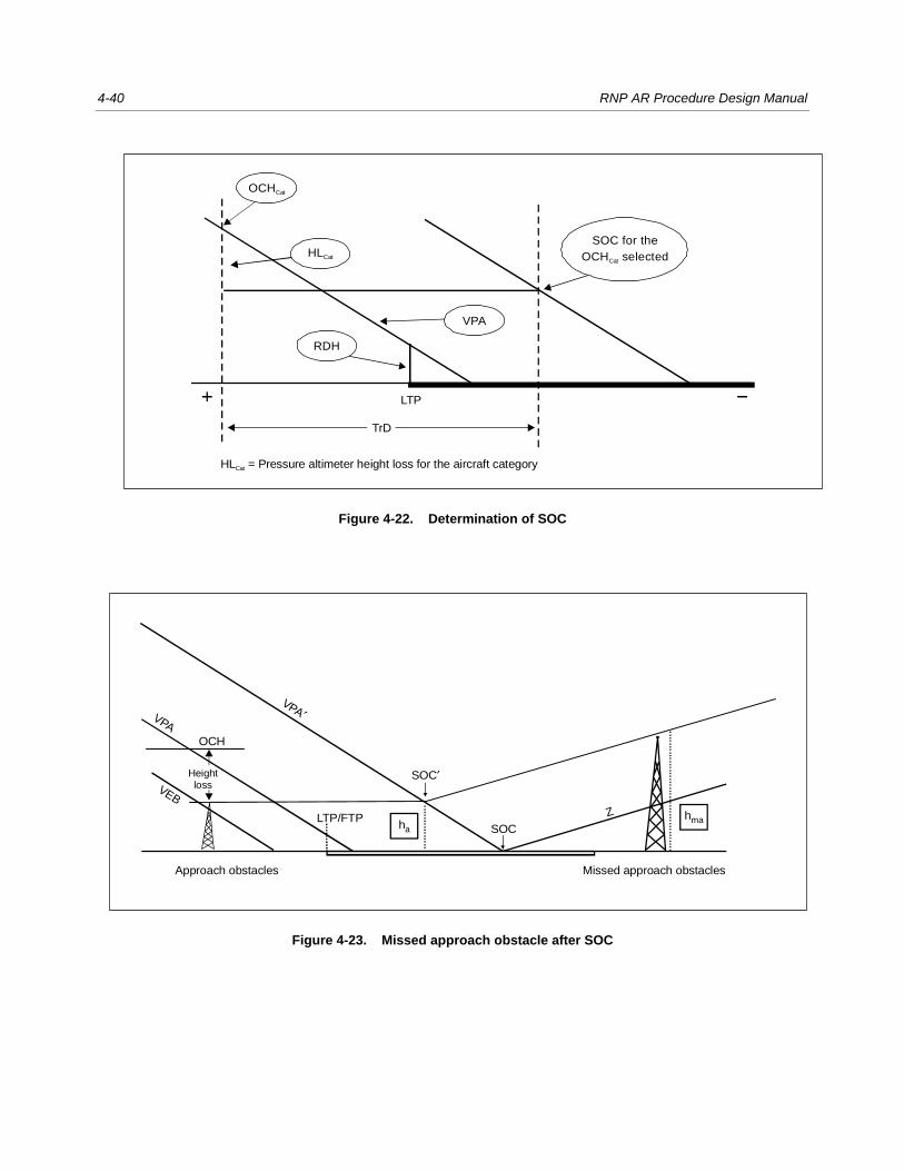
4-40 RNP AR Procedure Design Manual
Figure 4-22. Determination of SOC
Figure 4-23. Missed approach obstacle after SOC
LTP
TrD
HL = Pressure altimeter height loss for the aircraft categoryCat
SOC for the
OCH selectedCat
VPA
RDH
OCH Cat
HL Cat
OCH
Approach obstacles Missed approach obstacles
LTP/FTP Z
VPA′VPA
VEB
SOC
SOC′
ha
hma
Heightloss
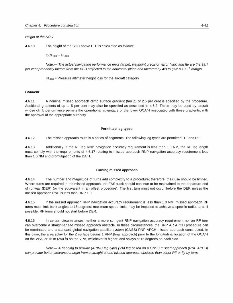
Chapter 4. Procedure construction 4-41
Height of the SOC
4.6.10 The height of the SOC above LTP is calculated as follows:
OCHCat − HLCat Note.— The actual navigation performance error (anpe), waypoint precision error (wpr) and fte are the 99.7 per cent probability factors from the VEB projected to the horizontal plane and factored by 4/3 to give a 10E–5 margin.
HLCat = Pressure altimeter height loss for the aircraft category
Gradient
4.6.11 A nominal missed approach climb surface gradient (tan Z) of 2.5 per cent is specified by the procedure.
Additional gradients of up to 5 per cent may also be specified as described in 4.6.2. These may be used by aircraft
whose climb performance permits the operational advantage of the lower OCA/H associated with these gradients, with
the approval of the appropriate authority.
Permitted leg types
4.6.12 The missed approach route is a series of segments. The following leg types are permitted: TF and RF.
4.6.13 Additionally, if the RF leg RNP navigation accuracy requirement is less than 1.0 NM, the RF leg length
must comply with the requirements of 4.6.17 relating to missed approach RNP navigation accuracy requirement less
than 1.0 NM and promulgation of the DA/H.
Turning missed approach 4.6.14 The number and magnitude of turns add complexity to a procedure; therefore, their use should be limited.
Where turns are required in the missed approach, the FAS track should continue to be maintained to the departure end
of runway (DER) (or the equivalent in an offset procedure). The first turn must not occur before the DER unless the
missed approach RNP is less than RNP 1.0.
4.6.15 If the missed approach RNP navigation accuracy requirement is less than 1.0 NM, missed approach RF
turns must limit bank angles to 15 degrees; maximum speed limits may be imposed to achieve a specific radius and, if
possible, RF turns should not start before DER.
4.6.16 In certain circumstances, neither a more stringent RNP navigation accuracy requirement nor an RF turn
can overcome a straight-ahead missed approach obstacle. In these circumstances, the RNP AR APCH procedure can
be terminated and a standard global navigation satellite system (GNSS) RNP APCH missed approach constructed. In
this case, the area splay for the Z surface begins 1 RNP (final approach) prior to the longitudinal location of the OCA/H
on the VPA, or 75 m (250 ft) on the VPA, whichever is higher, and splays at 15 degrees on each side.
Note.— A heading to altitude (ARINC leg type) (VA) leg based on a GNSS missed approach (RNP APCH) can provide better clearance margin from a straight ahead missed approach obstacle than either RF or fly-by turns.
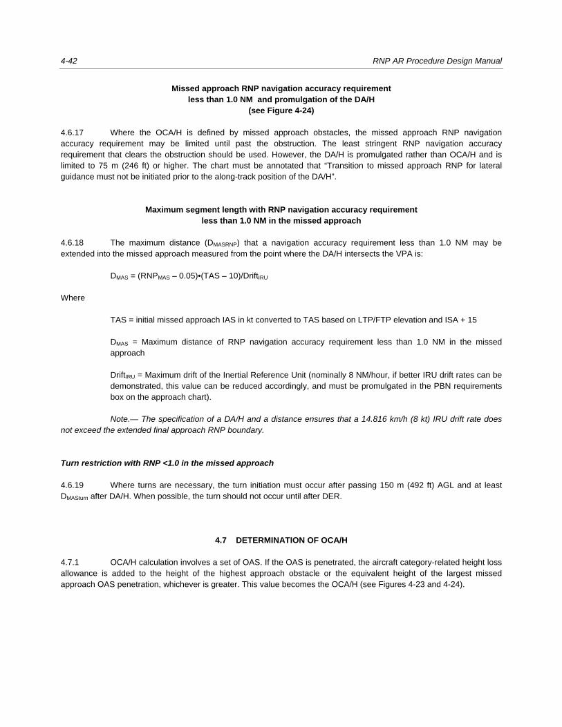
4-42 RNP AR Procedure Design Manual
Missed approach RNP navigation accuracy requirement less than 1.0 NM and promulgation of the DA/H
(see Figure 4-24)
4.6.17 Where the OCA/H is defined by missed approach obstacles, the missed approach RNP navigation
accuracy requirement may be limited until past the obstruction. The least stringent RNP navigation accuracy
requirement that clears the obstruction should be used. However, the DA/H is promulgated rather than OCA/H and is
limited to 75 m (246 ft) or higher. The chart must be annotated that “Transition to missed approach RNP for lateral
guidance must not be initiated prior to the along-track position of the DA/H”.
Maximum segment length with RNP navigation accuracy requirement less than 1.0 NM in the missed approach
4.6.18 The maximum distance (DMASRNP) that a navigation accuracy requirement less than 1.0 NM may be
extended into the missed approach measured from the point where the DA/H intersects the VPA is:
DMAS = (RNPMAS ‒ 0.05)•(TAS ‒ 10)/DriftIRU
Where
TAS = initial missed approach IAS in kt converted to TAS based on LTP/FTP elevation and ISA + 15
DMAS = Maximum distance of RNP navigation accuracy requirement less than 1.0 NM in the missed
approach
DriftIRU = Maximum drift of the Inertial Reference Unit (nominally 8 NM/hour, if better IRU drift rates can be
demonstrated, this value can be reduced accordingly, and must be promulgated in the PBN requirements
box on the approach chart).
Note.— The specification of a DA/H and a distance ensures that a 14.816 km/h (8 kt) IRU drift rate does not exceed the extended final approach RNP boundary.
Turn restriction with RNP <1.0 in the missed approach
4.6.19 Where turns are necessary, the turn initiation must occur after passing 150 m (492 ft) AGL and at least
DMASturn after DA/H. When possible, the turn should not occur until after DER.
4.7 DETERMINATION OF OCA/H
4.7.1 OCA/H calculation involves a set of OAS. If the OAS is penetrated, the aircraft category-related height loss
allowance is added to the height of the highest approach obstacle or the equivalent height of the largest missed
approach OAS penetration, whichever is greater. This value becomes the OCA/H (see Figures 4-23 and 4-24).
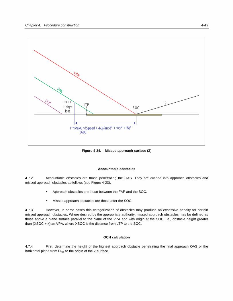
Chapter 4. Procedure construction 4-43
Figure 4-24. Missed approach surface (Z)
Accountable obstacles
4.7.2 Accountable obstacles are those penetrating the OAS. They are divided into approach obstacles and
missed approach obstacles as follows (see Figure 4-23).
• Approach obstacles are those between the FAP and the SOC.
• Missed approach obstacles are those after the SOC.
4.7.3 However, in some cases this categorization of obstacles may produce an excessive penalty for certain
missed approach obstacles. Where desired by the appropriate authority, missed approach obstacles may be defined as
those above a plane surface parallel to the plane of the VPA and with origin at the SOC, i.e., obstacle height greater
than (XSOC + x)tan VPA, where XSOC is the distance from LTP to the SOC.
OCH calculation
4.7.4 First, determine the height of the highest approach obstacle penetrating the final approach OAS or the
horizontal plane from Dveb to the origin of the Z surface.
OCH
Heightloss
LTP Z
VPA’
VPA
VEB
SOC
T * MaxGndSpeed + 4/3 anpe + wpr + fte 2 2 2
3600

4-44 RNP AR Procedure Design Manual
4.7.5 Next, reduce the heights of all missed approach obstacles to the height of equivalent approach obstacles
by the formula given below:
ha = [(hma + MOC) * cot Z – ( XZ – x)]/(cot VPA + cot Z)
where
ha = height of the equivalent approach obstacle
hma = height of the missed approach obstacle
X = distance of the obstacle from threshold (positive prior to the LTP threshold, negative after)
cot Z = cotangent of the Z surface angle
cot VPA = cotangent of the VPA
XZ = X coordinate of the point where ZX = ZLTP (origin of the missed approach surface).
4.7.6 MOC is 0 m/(0 ft) for a straight missed approach and RF turns; 30 m/(98 ft) for turns up to 15 degrees;
50 m/(164 ft) for turns greater than 15 degrees.
Straight missed approach
4.7.7 Determine OCH for the procedure by adding the height loss allowance defined in Table 4-5, to the height
of the highest approach obstacle (real or equivalent).
OCH = ha + HL margin
OCH calculation (turns in the missed approach — except RF)
4.7.8 Obstacle elevation/height shall be less than:
(OCA/H – HL) + (dz + do)tan Z – MOC
where
do = shortest distance from the obstacle to the earliest turning point (TP) (see Figures 4-23 and 4-24)
dz = horizontal distance from SOC to the earliest TP,
and MOC is:
50 m (164 ft) (Cat H, 40 m (132 ft)) for turns more than 15 degrees and 30 m (98 ft) for turns 15 degrees
or less.
4.7.9 If the obstacle elevation/height penetrates the Z surface, the OCA/H must be increased or the TP moved to
obtain the required clearance.
Chapter 4. Procedure construction 4-45
Application of RF legs in a turning missed approach
4.7.10 When an RF leg is used in a missed approach, the along-track distance during the RF turn for inclusion in
the track distance to calculate the gradient of the OAS is the arc length(s) based on a turn radius of (r – 0.1 NM). (See
Figures 4-9 b) and 4-25).
4.7.11 The height of the surface at any point on the track is constant radially across the surface. The slope is only
in the direction of the nominal flight vector tangent to the nominal track at any point and has a lateral slope of zero along
any radius.
4.7.12 Obstacle elevation/height shall be less than
(OCA/H – HL) + (dz + do) tan Z – MOC
where
do = distance measured along the arc(s), calculated for RF legs using a radius of (r – 0.1 NM)
dz = horizontal distance from SOC to the turning fix.
MOC applied in the formula calculating ha is 0 for RF missed approach legs.
4.7.13 If the obstacle elevation/height penetrates the Z surface, the OCA/H must be increased or the TP moved to
obtain the required clearance.
Figure 4-25. Radius for calculating track length for gradient
r – 0.1 NM
r
(Used to calculates = length for gradient)
0.1 NM
2 RNP
Note.— Use (r – 0.1 NM) radius to calculate arc length,, for gradient of surface.s

4-46 RNP AR Procedure Design Manual
Height loss margins Adjustments for high aerodrome elevations
4.7.14 The height loss margins in Table 4-5 shall be adjusted for airfield elevation higher than 900 m (2 953 ft).
The tabulated allowances shall be increased by two per cent of the RA margin per 300 m (984 ft) airfield elevation.
Adjustments for steep VPA
4.7.15 Procedures involving VPAs greater than 3.5 degrees or any angle when the nominal rate of descent (Vat
for the aircraft type x´ the sine of the VPA) exceeds 5 m/sec (1 000 ft/min) are nonstandard and require the following:
a) increase of height loss margin (which may be aircraft type-specific);
b) adjustment of the origin of the missed approach surface;
c) adjustment of the slope of the W surface;
d) re-survey of obstacles; and
e) the application of related operational constraints.
4.7.16 Such procedures are normally restricted to specifically approved operators and aircraft and are associated
with appropriate aircraft and crew restrictions. They are not to be used as a means to introduce noise abatement
procedures.
Table 4-5. Height loss margins
The following height loss margins shall be applied to all approach and equivalent approach obstacles
Margin using RA Margin using pressure altimeter
Aircraft category (Vat) Metres Feet Metres Feet
A – 169 km/h (90 kt) 13 42 40 130
B – 223 km/h (120 kt) 18 59 43 142
C – 260 km/h (140 kt) 22 71 46 150
D – 306 km/h (165 kt) 26 85 49 161
Note.— RA margins are used only for height loss adjustment.
Chapter 4. Procedure construction 4-47
Exceptions and adjustments
4.7.17 Values in the height loss table are calculated to account for aircraft using normal manual overshoot
procedures from OCA/H on the nominal approach path. Values in the table may be adjusted for specific aircraft types
where adequate flight and theoretical evidence is available, i.e., the height loss value corresponding to a probability of
1 × 10⁻⁵
(based on a missed approach rate 10–2
).
Margins for specific Vat
4.7.18 If a height loss/altimeter margin is required for a specific Vat, the following formulas apply (see also
PANS-OPS, Volume II, Part I, Section 4, Chapter 1, Tables I-4-1-1 and I-4-1-2):
Margin = (0.068Vat + 28.3) metres where Vat is in km/h
Margin = (0.125Vat + 28.3) metres where Vat is in kt
where Vat is the speed at threshold based on 1.3 times stall speed in the landing configuration at maximum certificated
landing mass.
Note.— The equations assume the aerodynamic and dynamic characteristics of the aircraft are directly related to the speed category. Thus, the calculated height loss/altimeter margins may not realistically represent small aircraft with Vat at maximum landing mass exceeding 165 kt.
Missed approach turns — restrictions
4.7.19 Where missed approach turns are necessary, the earliest point in the turn initiation area must be located
after a distance equivalent to 150 m (492 ft) AGL relative to a 2.5 per cent gradient or specified climb gradient, if higher,
with its origin at the SOC.
_____________________


5-1
Chapter 5
PUBLICATION AND CHARTING
5.1 INTRODUCTION
The general criteria in PANS-OPS, Volume II, Part I, Section 4, Chapter 9, Charting/AIP; and Part III, Section 5,
Publication, apply as modified in this chapter. See PANS-OPS, Volume II, Part III, Section 5, Chapter 2, for specific
aeronautical database publication requirements. The required navigation specification for any published procedure must
be included in the State AIP on the chart in the PBN requirements box or in the GEN section.
5.2 AERONAUTICAL CHART TITLES
Charts must be titled in accordance with Annex 4 — Aeronautical Charts, 10.5 for arrival procedures and 11.6 for
approach procedures.
5.3 APPROACH CHART IDENTIFICATION
The chart must be identified in accordance with Annex 4, 11.6, and with Doc 8168, Volume II, Part III, Section 5,
Chapter 1, 1.4 — Approach.
5.4 CHART NOTES
5.4.1 An RNP AR APCH chart requires the depiction of PBN requirements box in the chart plan view. The
applicable navigation specifications, including RNP AR APCH, applicable to the procedure, must be depicted in the PBN
requirements box. Additional PBN items shall be published in the PBN requirements box. The PBN requirements box
must include the navigation specification(s) used in the procedure design, any navigation sensor limitations and required
functionalities that are described as options in the navigation specification. Example items include:
a) RF required;
b) the navigation accuracy requirement if not part of the navigation specification.
Additional procedure requirements must be provided as chart notes. Example notes include:
c) “ATS surveillance service required”;
d) “Night operations N/A.”
5-2 RNP AR Procedure Design Manual
5.4.2 For RNP AR APCH procedures, the following specific notes may be required:
a) a note must be published on the chart that includes the specific authorization requirement; and
b) for RNP AR APCH procedures with missed approach RNP navigation accuracy requirement less than
1.0 NM, the following note is required: “Transition to missed approach RNP for lateral guidance must
not be initiated prior to the along-track position of DA/H”.
5.5 DEPICTION
Different required RNP navigation accuracy requirements on different initial segment legs must be charted with a note.
The required note may be charted with the applicable leg or as a procedure note with reference to the applicable leg. If
the same RNP navigation accuracy requirement applies to all initial and intermediate segments, then that navigation
accuracy requirement is depicted as indicated in 5.4.
5.6 MINIMA
5.6.1 OCA/H is published on approach charts for all RNP AR APCH procedures with one exception: for RNP AR
APCH procedures involving a MAS with RNP navigation accuracy requirements less than 1.0 NM, a DA/H shall be
published. An example of minima depiction is provided in PANS-OPS, Volume II, Part 1, Section 4, Chapter 9.
5.6.2 An OCA/H or DA/H for RNP 0.3 must be published for each RNP AR approach procedure. Additional
OCA/H or DA/H for RNP navigation accuracy requirements between 0.1 NM and 0.3 NM may be published as applicable.
_____________________
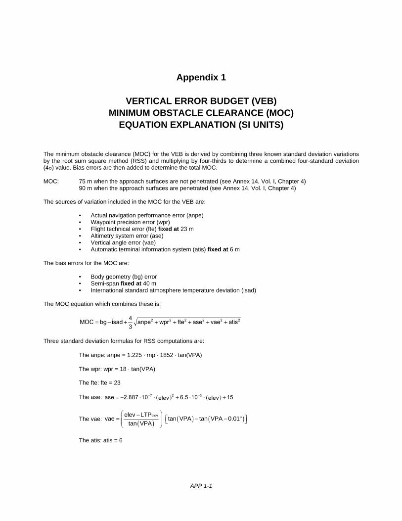
APP 1-1
Appendix 1
VERTICAL ERROR BUDGET (VEB) MINIMUM OBSTACLE CLEARANCE (MOC)
EQUATION EXPLANATION (SI UNITS)
The minimum obstacle clearance (MOC) for the VEB is derived by combining three known standard deviation variations by the root sum square method (RSS) and multiplying by four-thirds to determine a combined four-standard deviation (4σ) value. Bias errors are then added to determine the total MOC.
MOC: 75 m when the approach surfaces are not penetrated (see Annex 14, Vol. I, Chapter 4) 90 m when the approach surfaces are penetrated (see Annex 14, Vol. I, Chapter 4) The sources of variation included in the MOC for the VEB are: • Actual navigation performance error (anpe) • Waypoint precision error (wpr) • Flight technical error (fte) fixed at 23 m • Altimetry system error (ase) • Vertical angle error (vae) • Automatic terminal information system (atis) fixed at 6 m The bias errors for the MOC are: • Body geometry (bg) error • Semi-span fixed at 40 m • International standard atmosphere temperature deviation (isad) The MOC equation which combines these is:
= − + + + + + +2 2 2 2 2 24MOC bg isad anpe wpr fte ase vae atis3
Three standard deviation formulas for RSS computations are:
The anpe: anpe = 1.225 ⋅ rnp ⋅ 1852 ⋅ tan(VPA)
The wpr: wpr = 18 ⋅ tan(VPA) The fte: fte = 23
The ase: ( ) ( )− −= − ⋅ ⋅ + ⋅ ⋅ +27 3ase 2.887 10 6.5 10 15elev elev
The vae: ( ) ( ) ( ) −
= − − °
elevelev LTPvae tan VPA tan VPA 0.01
tan VPA
The atis: atis = 6
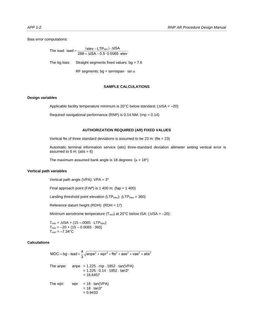
APP 1-2 RNP AR Procedure Design Manual
Bias error computations:
The isad: ( ) ⋅ Δ−=+ Δ − ⋅ ⋅
elev ISAelev LTPisad288 ISA 0.5 0.0065 elev
The bg bias: Straight segments fixed values: bg = 7.6
RF segments: bg = semispan ⋅ sin α
SAMPLE CALCULATIONS
Design variables Applicable facility temperature minimum is 20°C below standard: (ΔISA = –20) Required navigational performance (RNP) is 0.14 NM: (rnp = 0.14)
AUTHORIZATION REQUIRED (AR) FIXED VALUES
Vertical fte of three standard deviations is assumed to be 23 m: (fte = 23) Automatic terminal information service (atis) three-standard deviation altimeter setting vertical error is
assumed to 6 m: (atis = 6) The maximum assumed bank angle is 18 degrees: (α = 18°)
Vertical path variables Vertical path angle (VPA): VPA = 3° Final approach point (FAP) is 1 400 m: (fap = 1 400) Landing threshold point elevation (LTPelev): (LTPelev = 360) Reference datum height (RDH): (RDH = 17) Minimum aerodrome temperature (Tmin) at 20°C below ISA: (ΔISA = –20):
Tmin = ΔISA + (15 –.0065 ⋅ LTPelev)
Tmin = –20 + (15 – 0.0065 ⋅ 360) Tmin = –7.34°C
Calculations
= − + + + + + +2 2 2 2 2 24MOC bg isad anpe wpr fte ase vae atis3
The anpe: anpe = 1.225 ⋅ rnp ⋅ 1852 ⋅ tan(VPA)
= 1.225 ⋅ 0.14 ⋅ 1852 ⋅ tan3° = 16.6457
The wpr: wpr = 18 ⋅ tan(VPA)
= 18 ⋅ tan3° = 0.9433
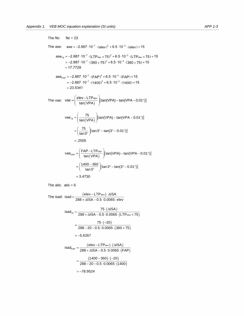
Appendix 1. VEB MOC equation explanation (SI units) APP 1-3
The fte: fte = 23
The ase: ( ) ( )− −= − ⋅ ⋅ + ⋅ ⋅ +27 3ase 2.887 10 6.5 10 15elev elev
( ) ( )
( ) ( )
− −
− −
= − ⋅ ⋅ + ⋅ ⋅ ++ += − ⋅ ⋅ + ⋅ ⋅ ++ +=
27 3elev elev75
27 3
ase 2.887 10 6.5 10 15LTP 75 LTP 752.887 10 6.5 10 15360 75 360 75
17.7729
( ) ( )
( ) ( )
− −
− −
= − ⋅ ⋅ + ⋅ ⋅ +
= − ⋅ ⋅ + ⋅ ⋅ +=
27 3FAP
27 3
ase 2.887 10 6.5 10 15FAP FAP2.887 10 6.5 10 151400 140023.5341
The vae: ( ) [ ] −= − − °
elevelev LTPvae tan(VPA) tan(VPA 0.01 )
tan VPA
( ) [ ]
[ ]
75
75vae tan(VPA) tan(VPA 0.01 )
tan VPA
75tan3 tan(3 0.01 )
tan3
.2505
= − − °
= ° − ° − ° °
=
( ) [ ]
[ ]
−= − − °
− = ° − ° − ° °
=
elev
FAP
FAP LTPvae tan(VPA) tan(VPA 0.01 )
tan VPA
1400 360tan3 tan(3 0.01 )
tan3
3.4730
The atis: atis = 6
The isad: ( )− ⋅ Δ
=+ Δ − ⋅ ⋅
elevelev LTP ISAisad
288 ISA 0.5 0.0065 elev
( )
( )
( )( )
⋅ Δ=
+ Δ − ⋅ ⋅ +
⋅ −=
− − ⋅ ⋅ +
= −
75elev
75 ISAisad
288 ISA 0.5 0.0065 LTP 75
75 20
288 20 0.5 0.0065 360 75
5.6267
( ) ( )
( )
( ) ( )( )
− ⋅ Δ=
+ Δ − ⋅ ⋅
− ⋅ −=
− − ⋅ ⋅
= −
elev
FAP
elev LTP ISAisad
288 ISA 0.5 0.0065 FAP
1400 360 20
288 20 0.5 0.0065 1400
78.9524
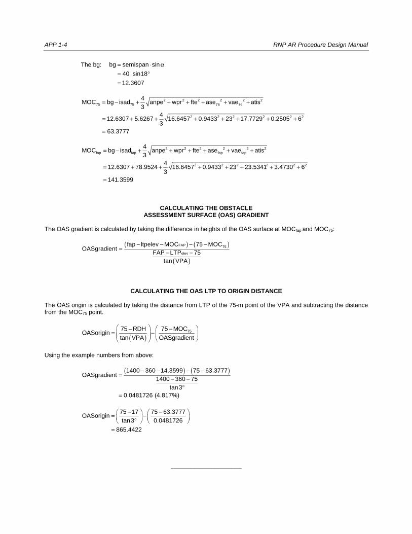
APP 1-4 RNP AR Procedure Design Manual
The bg: = ⋅ α= ⋅ °=
bg semispan sin
40 sin18
12.3607
= − + + + + + +
= + + + + + + +
=
2 2 2 2 2 2
75 75 76 76
2 2 2 2 2 2
4MOC bg isad anpe wpr fte ase vae atis
3
412.6307 5.6267 16.6457 0.9433 23 17.7729 0.2505 6
3
63.3777
= − + + + + + +
= + + + + + + +
=
2 2 2 2 2 2
fap fap fap fap
2 2 2 2 2 2
4MOC bg isad anpe wpr fte ase vae atis
3
412.6307 78.9524 16.6457 0.9433 23 23.5341 3.4730 6
3
141.3599
CALCULATING THE OBSTACLE ASSESSMENT SURFACE (OAS) GRADIENT
The OAS gradient is calculated by taking the difference in heights of the OAS surface at MOCfap and MOC75:
( ) ( )
( )
− − − −= − −
FAP 75
elev
fap ltpelev MOC 75 MOCOASgradient
FAP LTP 75
tan VPA
CALCULATING THE OAS LTP TO ORIGIN DISTANCE The OAS origin is calculated by taking the distance from LTP of the 75-m point of the VPA and subtracting the distance from the MOC75 point.
( ) −−= −
7575 MOC75 RDHOASorigin
tan VPA OASgradient
Using the example numbers from above:
( ) ( )− − − −=
− −°
=
1400 360 14.3599 75 63.3777OASgradient
1400 360 75
tan3
0.0481726 (4.817%)
− − = − °
=
75 17 75 63.3777OASorigin
tan3 0.0481726
865.4422
_____________________

APP 2-1
Appendix 2
VERTICAL ERROR BUDGET (VEB) MINIMUM OBSTACLE CLEARANCE (MOC) EQUATION EXPLANATION (NON-SI UNITS)
The required minimum obstacle clearance (MOC) for the VEB is derived by combining known three standard deviation variations by the RSS method and multiplying by four-thirds to determine a combined four standard deviation (4σ) value. Bias errors are then added to determine the total MOC. MOC: 250 ft when the approach surfaces are not penetrated (see Annex 14, Vol. I, Chapter 4) 300 ft when the approach surfaces are penetrated (see Annex 14, Vol. I, Chapter 4) The sources of variation included in the MOC for the VEB are: • Actual navigation performance error (anpe) • Waypoint precision error (wpr) • Flight technical error (fte) fixed at 75 ft • Altimetry system error (ase) • Vertical angle error (vae) • Automatic terminal information system (atis) fixed at 20 ft The bias errors for the MOC are: • Body geometry (bg) error • Semi-span fixed at 132 • International standard atmosphere temperature deviation (isad) The MOC equation which combines these is:
= − + + + + + +2 2 2 2 2 24MOC bg isad anpe wpr fte ase vae atis3
Three standard deviation formulas for RSS computations:
The anpe: = ⋅ ⋅ ⋅1852anpe 1.225 rnp tanVPA0.3048
The wpr: = ⋅wpr 60 tanVPA The fte: fte = 75
The ase: ( ) ( )− −= − ⋅ ⋅ + ⋅ ⋅ +28 3ase 8.8 10 6.5 10 50elev elev
The vae: [ ]− = − − °
elevelev LTPvae tan tan( 0.01 )
tanθ θ
θ
The atis: atis = 20
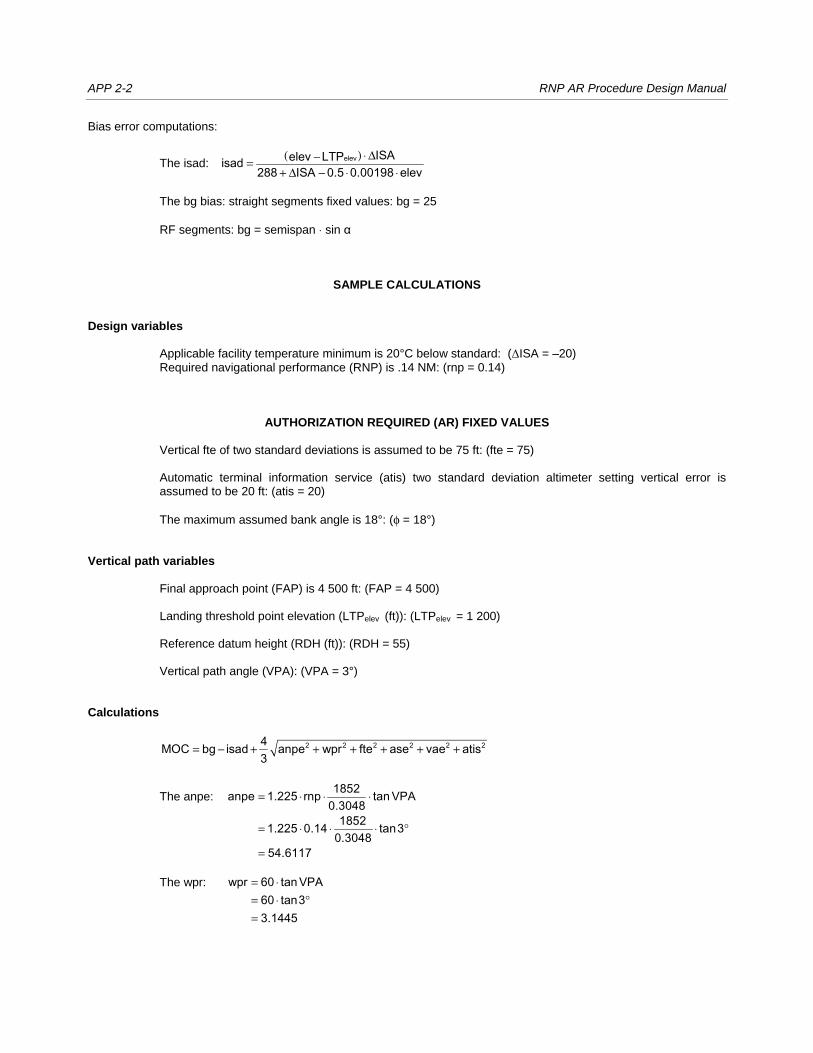
APP 2-2 RNP AR Procedure Design Manual
Bias error computations:
The isad: ( ) ⋅ Δ−=
+ Δ − ⋅ ⋅elev ISAelev LTPisad
288 ISA 0.5 0.00198 elev
The bg bias: straight segments fixed values: bg = 25
RF segments: bg = semispan ⋅ sin α
SAMPLE CALCULATIONS Design variables Applicable facility temperature minimum is 20°C below standard: (ΔISA = –20) Required navigational performance (RNP) is .14 NM: (rnp = 0.14)
AUTHORIZATION REQUIRED (AR) FIXED VALUES Vertical fte of two standard deviations is assumed to be 75 ft: (fte = 75) Automatic terminal information service (atis) two standard deviation altimeter setting vertical error is
assumed to be 20 ft: (atis = 20)
The maximum assumed bank angle is 18°: (φ = 18°) Vertical path variables Final approach point (FAP) is 4 500 ft: (FAP = 4 500) Landing threshold point elevation (LTPelev (ft)): (LTPelev = 1 200) Reference datum height (RDH (ft)): (RDH = 55) Vertical path angle (VPA): (VPA = 3°) Calculations
= − + + + + + +2 2 2 2 2 24MOC bg isad anpe wpr fte ase vae atis3
The anpe: = ⋅ ⋅ ⋅
= ⋅ ⋅ ⋅ °
=
1852anpe 1.225 rnp tanVPA0.304818521.225 0.14 tan30.3048
54.6117
The wpr: = ⋅= ⋅ °=
wpr 60 tanVPA60 tan33.1445
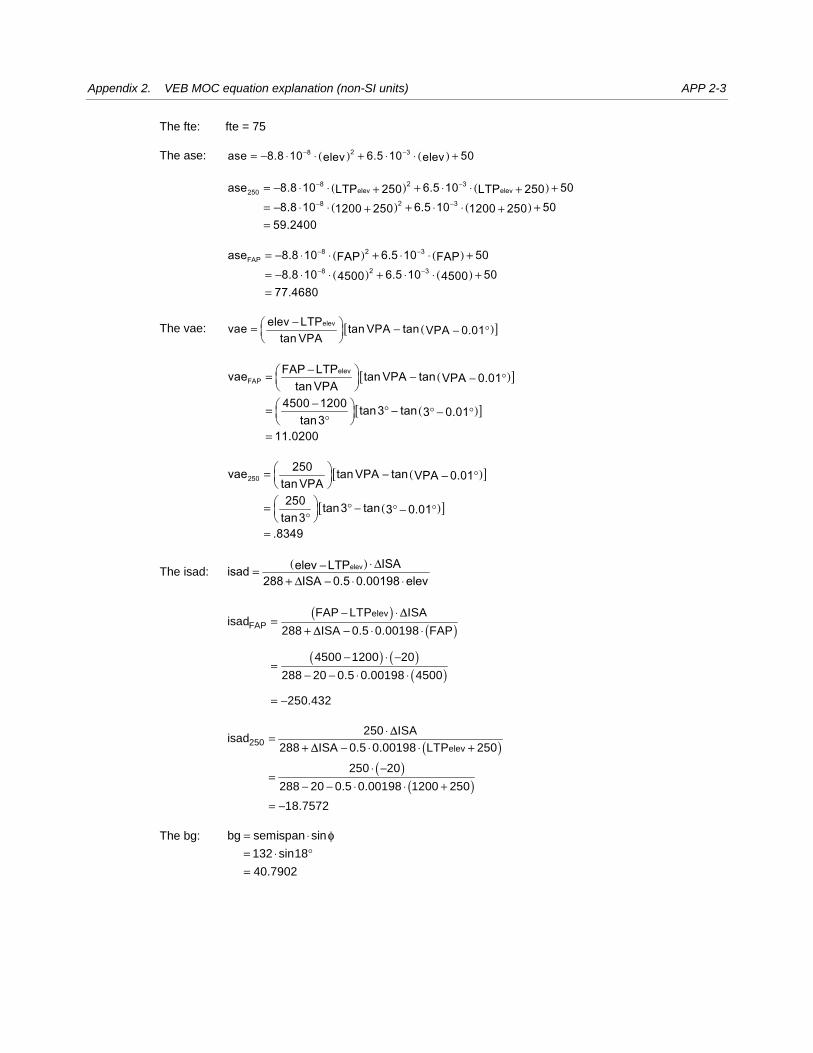
Appendix 2. VEB MOC equation explanation (non-SI units) APP 2-3
The fte: fte = 75
The ase: ( ) ( )− −= − ⋅ ⋅ + ⋅ ⋅ +28 3ase 8.8 10 6.5 10 50elev elev
( ) ( )
( ) ( )
− −
− −
= − ⋅ ⋅ + ⋅ ⋅ ++ += − ⋅ ⋅ + ⋅ ⋅ ++ +=
28 3elev elev250
28 3
ase 8.8 10 6.5 10 50LTP 250 LTP 2508.8 10 6.5 10 501200 250 1200 250
59.2400
( ) ( )
( ) ( )
− −
− −
= − ⋅ ⋅ + ⋅ ⋅ +
= − ⋅ ⋅ + ⋅ ⋅ +=
28 3FAP
28 3
ase 8.8 10 6.5 10 50FAP FAP8.8 10 6.5 10 504500 4500
77.4680
The vae: ( )[ ]− = − − °
elevelev LTPvae tan VPA tan VPA 0.01tan VPA
( )[ ]
( )[ ]
− = − − °
− = ° − ° − ° ° =
elevFAP
FAP LTPvae tanVPA tan VPA 0.01tanVPA4500 1200 tan3 tan 3 0.01tan3
11.0200
( )[ ]
( )[ ]
= − − ° = ° − ° − ° °
=
250250vae tanVPA tan VPA 0.01tanVPA250 tan3 tan 3 0.01tan3
.8349
The isad: ( ) ⋅ Δ−=
+ Δ − ⋅ ⋅elev ISAelev LTPisad
288 ISA 0.5 0.00198 elev
( )
( )
( ) ( )( )
− ⋅=
+ − ⋅ ⋅
− ⋅ −=
− − ⋅ ⋅
= −
elev
FAP
FAP LTP ISAisad
288 ISA 0.5 0.00198 FAP
4500 1200 20
288 20 0.5 0.00198 4500
250.432
ΔΔ
( )
( )( )
⋅=+ − ⋅ ⋅ +
⋅ −=
− − ⋅ ⋅ +
= −
250elev
250 ISAisad
288 ISA 0.5 0.00198 LTP 250
250 20
288 20 0.5 0.00198 1200 250
18.7572
ΔΔ
The bg: = ⋅= ⋅ °=
bg semispan sin
132 sin18
40.7902
φ
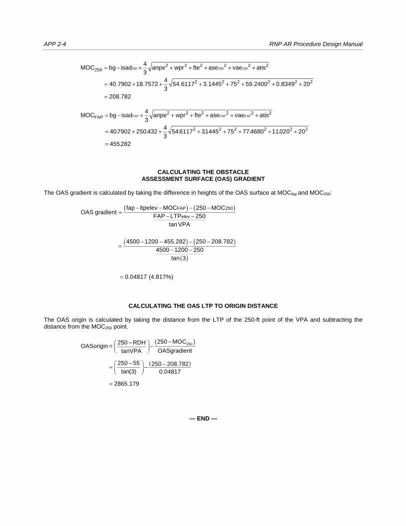
APP 2-4 RNP AR Procedure Design Manual
= − + + + + + +
= + + + + + + +
=
250 250 2502 2 2 2 2 2
250
2 2 2 2 2 2
4MOC bg isad anpe wpr fte ase vae atis
3
440.7902 18.7572 54.6117 3.1445 75 59.2400 0.8349 20
3
208.782
. . . . . .
.
= − + + + + + +
= + + + + + + +
=
FAP FAP FAP2 2 2 2 2 2
FAP
2 2 2 2 2 2
4MOC bg isad anpe wpr fte ase vae atis
3
4407902 250 432 54 6117 31445 75 77 4680 11020 20
3
455 282
CALCULATING THE OBSTACLE ASSESSMENT SURFACE (OAS) GRADIENT
The OAS gradient is calculated by taking the difference in heights of the OAS surface at MOCfap and MOC250:
( ) ( )
( ) ( )
( )
− − − −=
− −
− − − −=
− −
=
FAP 250
elev
fap ltpelev MOC 250 MOCOAS gradient
FAP LTP 250
tan VPA
4500 1200 455.282 250 208.782
4500 1200 250
tan 3
0.04817 (4.817%)
CALCULATING THE OAS LTP TO ORIGIN DISTANCE The OAS origin is calculated by taking the distance from the LTP of the 250-ft point of the VPA and subtracting the distance from the MOC250 point.
( )
( )
250250 MOC250 RDHOASorigin =
OASgradienttanVPA
250 55 250 208.782
tan(3) 0.04817
2865.179
−− −
− −= −
=
— END —