do - it - yourself and troubleshooting guide for no. 12 ...shoesystemsplus.com/assets/images/parts...
TRANSCRIPT

1
Do - it - yourselfMaintenance
andTroubleshooting
Guidefor
NO. 12 LANDISSHOE STITCHERS
Compliments of:
SHOESYSTEMS
PLUS249 West Main Street
Goshen, NY 10924Ph: 800-354-6278 Fax: 845-291-7097
www.shoesystemsplus.com

3
Dear Shoemaker:
In presenting this manual on the Landis 12-series stitchers, it is our aim to make do-it-yourself repair and troubleshooting as simple as possible. We have taken each significant part and operation separately and explained it in a manner that, we believe, will enable any operator to troubleshoot and/or repair his stitcher to achieve satisfactory results.
These instructions should be studied before attempting to do work on a machine. Time given to the thorough understanding of the particu-lar machine problem or difficulty you are experiencing will be money saved when you are able to correct the problem yourself with the aid of this manual, and your machine is put back in operation without that expensive service call by a repairman.
We at Shoe Systems Plus are always striving to improve our ability to assist you in your operation. So, if you are unable to accomplish the repair yourself, please call us and we will do our best to help you get that important stitcher back in operation!
249 West Main StreetGoshen, NY 10924
800-354-6278
4
Having Trouble Finding Parts?Call for your free copy of our
2001 Parts & Supplies Catalogue
Our staff will be happy to help you locate the parts you need. As machinery rebuilders, we can counsel you when dealing with machinery problems, in many cases saving you time and money by avoiding unnecessary parts re-placement and service calls.
5
Do - It - Yourself Maintenance andTroubleshooting Guide for
No. 12 Landis Shoe Stitchers
OIL MACHINE THOROUGHLY ONCE A DAY Clean wax pot frequently and add wax occasionally. Old wax will cause thread to break.
Machine must be well maintained and wax in wax pot must be in good condition before attempting to sew. Thread rolls must turn freely before making any adjustments on machine. Clean thread rolls with kerosene and oil them thoroughly. Rubber strippers should be replaced if worn out.
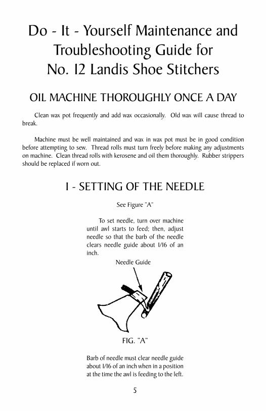
I - SETTING OF THE NEEDLESee Figure “A”
To set needle, turn over machine until awl starts to feed; then, adjust needle so that the barb of the needle clears needle guide about 1/16 of an inch.
Barb of needle must clear needle guide about 1/16 of an inch when in a position at the time the awl is feeding to the left.
Needle Guide
FIG. “A”

6
II - SETTING AND LINING UP AWL To take out awl (Fig. “A”), swing shoe guide bracket to the front; in this position, socket wrench can reach awl clamp nut. See Fig. “B”.
Set awl with needle so it clears needle about 1/16 of an inch. Keep awl sharp and do not use a bent awl.
Awl must be in line with the needle. (See Fig. “C”, below.) When machine feeds, the awl springs to the right, therefore, perfect adjustment is obtained when awl is slightly to the left of the needle. Should the awl be out of line, try a new awl and, if it appears the same, then line up awl. To line up awl, loosen screw No. L26-305 and turn adjustment screw No. L26-205. See Fig. “B”.
To line up awl loosen screw No. L26-305 and turn ad-justment screw No. L26-205 to take out awl, push back knob L30-302E and swing guide brackets to the front.
Awl must always be set slight-ly to the left of needle.
FIG. “C”
FIG. “A” Awl
FIG. “B”
PRESSER FOOT
SHOE GUIDE
12-L30-302E
12-L26-205
12-L26-305

7
III - LOOPER No. L29-5 Set Looper so that it throws thread 1/16 of an inch above barb of needle. Looper must also clear threadhook No. L29-6. Sharp edges on looper will cause the thread to fray or break. (See Figures “D”, “E” and “F” below.)
LooperMustClear
ThreadHook
Set Looper so that it throws thread 1/16 of an inch above barb of needle.
FIG. “D”FIG. “E”Front View
Side View
FIG. “F”

8
IV - LIFTER No. L29-10 Thread lifter should be set so that it passes as close as possible to point of needle and must separate the two threads when needle comes up at this point. Thread Lifter should be set close to shuttle. See Figs. “G” and “H”.
To adjust lifter No. L29-10 up or down, loosen screw No. L29-310 and turn eccentric No. L29-210 to get right position.
The bobbin case is retained by the latch at top of the door. The fulcrum pin for the latch is an eccentric retained by a small set screw on inside of door. The bobbin retainer should be set so that there is about 1/32 of an inch space between the retainer and the bobbin case. This will permit the thread to go freely around the shuttle. The thread must not stick when passing between the bobbin case and the retainer. The eccentric fulcrum pin is an adjustment for this purpose. Be sure door is latched whenever bobbin case is in machine. Failure to do this will jam the bobbin case against the lifter. Thread Lifter should be set close to shuttle at this point.
V - TENSION Adjust tension to prevent an uneven amount of thread being drawn from the wax pot.
If tension is too tight, the lock will be placed unevenly in the sole. The result will be ripped work.
Before adjusting the tension be sure that thread rolls and the felt washers of the ten-sion are clean.
Strippers should be replaced when worn out.
Adjust stripper tight enough so that it strips the wax off the thread. When stripper is too tight it will act like a tension and will cause thread to break.
FIG. “G”
FIG. “H”
L29-10
Thread lifter must pass as close as possible to point of needle.
Needle GuideLATCH12-L22-5
BOBBIN RETAINER12-L22-3
FULCRUM PIN12-L22-505
L29-310
L29-210
9
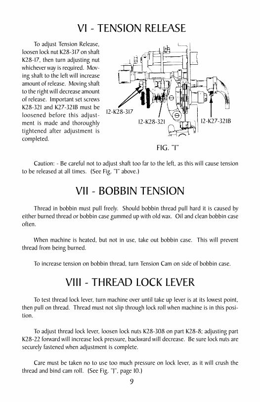
VI - TENSION RELEASE To adjust Tension Release, loosen lock nut K28-317 on shaft K28-17, then turn adjusting nut whichever way is required. Mov-ing shaft to the left will increase amount of release. Moving shaft to the right will decrease amount of release. Important set screws K28-321 and K27-321B must be loosened before this adjust-ment is made and thoroughly tightened after adjustment is completed.
Caution: - Be careful not to adjust shaft too far to the left, as this will cause tension to be released at all times. (See Fig. “I” above.)
VII - BOBBIN TENSION Thread in bobbin must pull freely. Should bobbin thread pull hard it is caused by either burned thread or bobbin case gummed up with old wax. Oil and clean bobbin case often.
When machine is heated, but not in use, take out bobbin case. This will prevent thread from being burned.
To increase tension on bobbin thread, turn Tension Cam on side of bobbin case.
VIII - THREAD LOCK LEVER To test thread lock lever, turn machine over until take up lever is at its lowest point, then pull on thread. Thread must not slip through lock roll when machine is in this posi-tion.
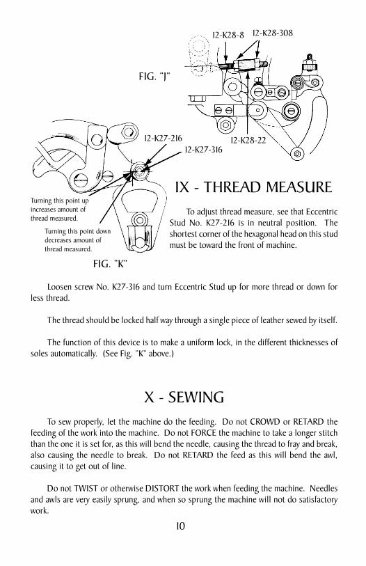
To adjust thread lock lever, loosen lock nuts K28-308 on part K28-8; adjusting part K28-22 forward will increase lock pressure, backward will decrease. Be sure lock nuts are securely fastened when adjustment is complete.
Care must be taken no to use too much pressure on lock lever, as it will crush the thread and bind cam roll. (See Fig. “J”, page 10.)
FIG. “I”
12-K28-321 12-K27-321B12-K28-317
10
IX - THREAD MEASURE To adjust thread measure, see that Eccentric Stud No. K27-216 is in neutral position. The shortest corner of the hexagonal head on this stud must be toward the front of machine.
Loosen screw No. K27-316 and turn Eccentric Stud up for more thread or down for less thread.
The thread should be locked half way through a single piece of leather sewed by itself.
The function of this device is to make a uniform lock, in the different thicknesses of soles automatically. (See Fig. “K” above.)
X - SEWING To sew properly, let the machine do the feeding. Do not CROWD or RETARD the feeding of the work into the machine. Do not FORCE the machine to take a longer stitch than the one it is set for, as this will bend the needle, causing the thread to fray and break, also causing the needle to break. Do not RETARD the feed as this will bend the awl, causing it to get out of line.
Do not TWIST or otherwise DISTORT the work when feeding the machine. Needles and awls are very easily sprung, and when so sprung the machine will not do satisfactory work.
Turning this point up increases amount of thread measured.
Turning this point down decreases amount of thread measured.
FIG. “K”
12-K27-21612-K27-316
FIG. “J”
12-K28-22
12-K28-8 12-K28-308

11
All that is required of the operator is to guide the work, and the machine will feed properly and sew a smooth, even stitch.
The machine may be in perfect adjustment and still fail to do satisfactory sewing if the operator is careless in handling his work.
SPEED OF THE MACHINE The No. 12 Shoe Stitcher should be run at a speed of 350 revolutions per minute. To get this speed the rear shaft should run about 600 revolutions per minute.
INSTRUCTIONS FOR SETTING MODEL 12K STITCHER PRESSERFOOT MECHANISM
The presserfoot is locked when the roll 12K-27-25 raises the presserfoot bar locking dog 12K-27-26 sufficiently to grip and lock the presserfoot bar nut 12K-27-331.
The presserfoot bar sleeve adjusting nut 12K-27-327, when assembled, is screwed on to adjusting sleeve 12K-27-27 so that sleeve protrudes through nut about a full thread. This location of nut will provide ample clearance for the action of the mechanism. The average adjusted position of nut 12K-27-327 is about 1/8” above block 12K-27-30.
(continued on page 12)
FIG. “L”
12-K27-7
12-K27-6
PRESSERFOOT
NEEDLE PLATE
12-K27-1612-K27-201
12-K27-27
12-K27-33112-K27-31 12-K27-26
12-K27-25 ASSM.CLEARANCE
12-K27-24
CAM
12-K27-3012-K27-327
12-K27-327B12-K27-327A
12-K27-70612-K27-32
12-K27-506

12
SETTING MODEL 12K STITCHER - continued
The adjustment to lock the mechanism is made with the presserfoot cam lever 12K-27-24 in highest position at working end and in this position, the cam lever eccentric, 12K-27-25 is up. In this position, the presserfoot should be locked.
To adjust -- the sleeve 12K-27-27 should be up as shown on the drawing -- now back out adjusting screw 12K-27-327A to lower the sleeve with dog 12K-27-26 until it contacts the cam lever eccentric roll. Continued dropping will then raise the dog until it binds the nut 12K-27-331. The adjustment is complete when you cannot raise the presserfoot raising lever, part 12K-27-7, after which the adjusting screw should be locked with binding screw 12K-27-327B.
NEEDLE PLATE ADJUSTMENT
SIZE OF THREAD, NEEDLES AND AWLS A little experience will soon enable the operator to select the size of needle best suited for his work. The following table may be used as a general guide for the size of needles used for the different sizes of thread. For 4 to 6 stitches per inch, 9 cord thread, No. 24-45 Needle and 24-43 Awl. For 7 to 9 stitches per inch, 8 cord thread, No. 23-47 Needle and 23-45 Awl. For 10 stitches per inch, 7 cord thread, No. 22-50 Needle and 22-47 Awl. For 12 stitches per inch, 6 cord thread, No. 21-52 Needle and 21-50 Awl. For 14 stitches per inch, 5 cord thread, No. 20-54 Needle and 20-52 Awl. Landis Needles are numbered 24-45, 23-47, 22-50, 21-52 and 20-54. Landis Awls are numbered 24-43, 23-45, 22-47, 21-50 and 20-52. The number 20-54 is the smallest Needle and the number 20-52 is the smallest Awl.
Figure “M” shows the needle plate adjustment in side and top views. To adjust needle slot to the awl, release screw, K22-301B, (side view) and turn eccentric dowel, K22-201B, in direction required to properly position needle slot to clear the awl.
FIG. “M”12-K22-301B 12-K22-201B
12-K24-308
HEAD 12-K22-IN
AWL
NEEDLE PLATE
NEEDLE PLATE AWL

13
THREADING DIAGRAMFOR
SEWING OR MACHINE THREAD
FIG. “N”
THREADTO LOOPER
COLUMN
THRE
AD

14
THREADING DIAGRAMFOR
BOBBIN WINDER THREAD
FIG. “O”Spool to Bobbin
Threading Diagram
BOBBIN WINDERSHIFTER HANDLE
THREAD TOBOBBIN WINDER
WAX POT
SHELFBRACKET
THREAD GUIDE
COLUMN
THRE
AD
15
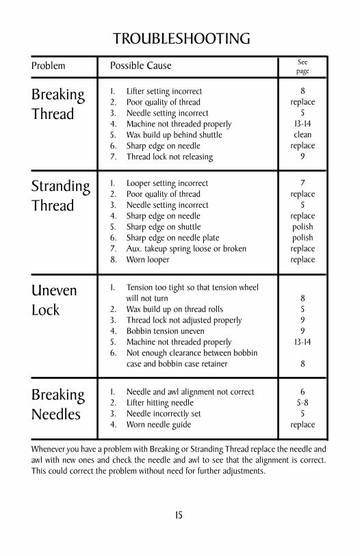
TROUBLESHOOTING
Problem Possible Cause Seepage
BreakingThread
Stranding Thread
UnevenLock
BreakingNeedles
Whenever you have a problem with Breaking or Stranding Thread replace the needle and awl with new ones and check the needle and awl to see that the alignment is correct. This could correct the problem without need for further adjustments.
1. Lifter setting incorrect2. Poor quality of thread3. Needle setting incorrect4. Machine not threaded properly5. Wax build up behind shuttle6. Sharp edge on needle7. Thread lock not releasing
8replace
513-14clean
replace9
1. Looper setting incorrect2. Poor quality of thread3. Needle setting incorrect4. Sharp edge on needle5. Sharp edge on shuttle6. Sharp edge on needle plate7. Aux. takeup spring loose or broken8. Worn looper
7replace
5replacepolishpolishreplacereplace
1. Tension too tight so that tension wheel will not turn2. Wax build up on thread rolls3. Thread lock not adjusted properly4. Bobbin tension uneven5. Machine not threaded properly6. Not enough clearance between bobbin case and bobbin case retainer
8599
13-14
8
1. Needle and awl alignment not correct2. Lifter hitting needle3. Needle incorrectly set4. Worn needle guide
65-85
replace