dlc3000 series digital level...
TRANSCRIPT
www.Fisher.com
Introduction
Principle of Operation
Installation
Setup and Calibration
Troubleshooting and Maintenance
Replaceable Parts
375 Field Communicator Basics
Loop Schematics/Nameplates
Glossary
Index
D10
2748
X01
2
Instruction ManualForm 5631April 2005DLC3000 Series
FIELDVUE� Type DLC3000Digital Level Controllers
This manual applies to:
Type DLC3010 Model 375 FieldCommunicator
DeviceRevision
FirmwareRevision
HardwareRevision
Device DescriptionRevison
1 8 1 2
1
2
3
4
5
6
A
B
9
10
Glossary
Index
DLC3000 Series
i
Unfold This Sheet to See theModel 375 Field Communicator
Menu Structure
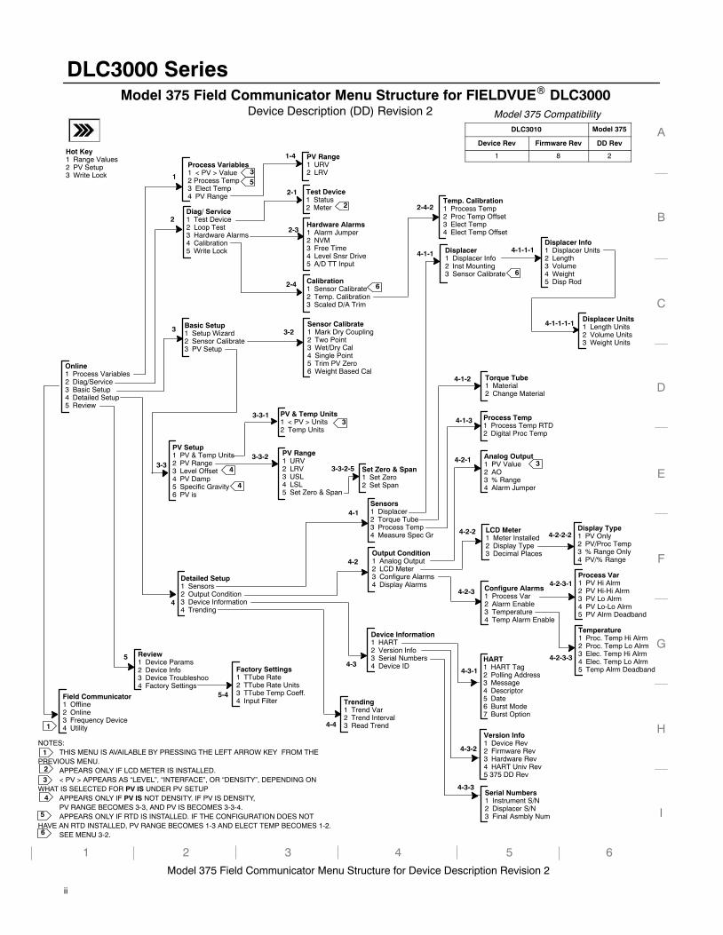
Process Variables1 < PV > Value2 Process Temp3 Elect Temp4 PV Range
Serial Numbers1 Instrument S/N2 Displacer S/N3 Final Asmbly Num
Display Type1 PV Only2 PV/Proc Temp3 % Range Only4 PV/% Range
Process Var1 PV Hi Alrm2 PV Hi-Hi Alrm3 PV Lo Alrm4 PV Lo-Lo Alrm5 PV Alrm Deadband
Online1 Process Variables2 Diag/Service3 Basic Setup4 Detailed Setup5 Review
Version Info1 Device Rev2 Firmware Rev3 Hardware Rev4 HART Univ Rev5 375 DD Rev
Temperature1 Proc. Temp Hi Alrm2 Proc. Temp Lo Alrm3 Elec. Temp Hi Alrm4 Elec. Temp Lo Alrm5 Temp Alrm Deadband
Output Condition1 Analog Output2 LCD Meter3 Configure Alarms4 Display Alarms
PV Setup1 PV & Temp Units2 PV Range3 Level Offset4 PV Damp5 Specific Gravity6 PV is
Sensor Calibrate1 Mark Dry Coupling2 Two Point3 Wet/Dry Cal4 Single Point5 Trim PV Zero6 Weight Based Cal
Diag/ Service1 Test Device2 Loop Test3 Hardware Alarms4 Calibration5 Write Lock Displacer
1 Displacer Info2 Inst Mounting3 Sensor Calibrate
Device Information1 HART2 Version Info3 Serial Numbers4 Device ID
Sensors1 Displacer2 Torque Tube3 Process Temp4 Measure Spec Gr
Displacer Info1 Displacer Units2 Length3 Volume4 Weight5 Disp Rod
Torque Tube1 Material2 Change Material
Basic Setup1 Setup Wizard2 Sensor Calibrate3 PV Setup
Trending1 Trend Var2 Trend Interval3 Read Trend
LCD Meter1 Meter Installed2 Display Type3 Decimal Places
Calibration1 Sensor Calibrate2 Temp. Calibration3 Scaled D/A Trim
Model 375 Field Communicator Menu Structure for Device Description Revision 2
Field Communicator1 Offline2 Online3 Frequency Device4 Utility
Hardware Alarms1 Alarm Jumper2 NVM3 Free Time4 Level Snsr Drive5 A/D TT Input
Detailed Setup1 Sensors2 Output Condition3 Device Information4 Trending
Device Description (DD) Revision 2
NOTES:THIS MENU IS AVAILABLE BY PRESSING THE LEFT ARROW KEY FROM THE
PREVIOUS MENU.APPEARS ONLY IF LCD METER IS INSTALLED.< PV > APPEARS AS “LEVEL”, “INTERFACE”, OR “DENSITY”, DEPENDING ON
WHAT IS SELECTED FOR PV IS UNDER PV SETUPAPPEARS ONLY IF PV IS NOT DENSITY. IF PV IS DENSITY,PV RANGE BECOMES 3-3, AND PV IS BECOMES 3-3-4.APPEARS ONLY IF RTD IS INSTALLED. IF THE CONFIGURATION DOES NOT
HAVE AN RTD INSTALLED, PV RANGE BECOMES 1-3 AND ELECT TEMP BECOMES 1-2.SEE MENU 3-2.
1 2 3 4 5
A
B
C
D
E
F
G
H
I
2-32
2-4
3-3
4
4-1
4-1-1
1
3
Configure Alarms1 Process Var2 Alarm Enable3 Temperature4 Temp Alarm Enable
Test Device1 Status2 Meter
2-1
1
PV Range1 URV2 LRV3 USL4 LSL5 Set Zero & Span
3-3-2
6
Process Temp1 Process Temp RTD2 Digital Proc Temp
HART1 HART Tag2 Polling Address3 Message4 Descriptor5 Date6 Burst Mode7 Burst Option
Analog Output1 PV Value2 AO3 % Range4 Alarm Jumper
Review1 Device Params2 Device Info3 Device Troubleshoo4 Factory Settings
1
5
4-2
4-3
4-4
4-1-2
4-1-3
3-2
4-2-2
4-3-1
4-3-2
4-3-3
4-2-3-1
1-4 PV Range1 URV2 LRV
2
2
Factory Settings1 TTube Rate2 TTube Rate Units3 TTube Temp Coeff.4 Input Filter
PV & Temp Units1 < PV > Units2 Temp Units
Set Zero & Span1 Set Zero2 Set Span
Displacer Units1 Length Units2 Volume Units3 Weight Units
4-2-3
4-2-1
4-2-3-3
3
3
3
4
4
4
3
3-3-1
5-4
4-2-2-2
3-3-2-5
5
6
4-1-1-1
4-1-1-1-1
5
6
6
Hot Key1 Range Values2 PV Setup3 Write Lock
Temp. Calibration1 Process Temp2 Proc Temp Offset3 Elect Temp4 Elect Temp Offset
2-4-2
Model 375 Field Communicator Menu Structure for FIELDVUE� DLC3000
DLC3000 Series
ii
Model 375 CompatibilityDLC3010 Model 375
Device Rev Firmware Rev DD Rev
1 8 2
DLC3000 Series
iii
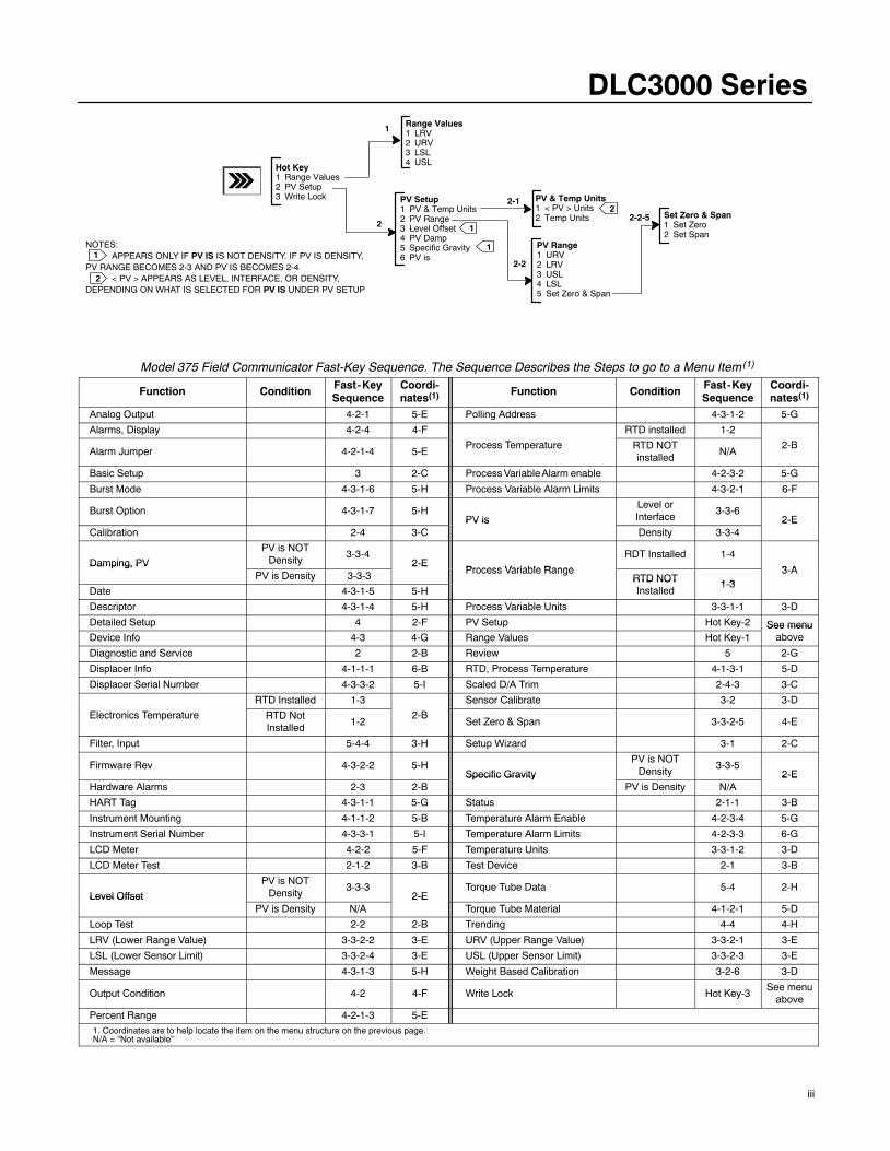
Hot Key1 Range Values2 PV Setup3 Write Lock
1 Range Values1 LRV2 URV3 LSL4 USL
PV Setup1 PV & Temp Units2 PV Range3 Level Offset4 PV Damp5 Specific Gravity6 PV is
2
PV & Temp Units1 < PV > Units2 Temp Units
2-1
PV Range1 URV2 LRV3 USL4 LSL5 Set Zero & Span
2-2
1
1
NOTES:APPEARS ONLY IF PV IS IS NOT DENSITY. IF PV IS DENSITY,
PV RANGE BECOMES 2-3 AND PV IS BECOMES 2-4< PV > APPEARS AS LEVEL, INTERFACE, OR DENSITY,
DEPENDING ON WHAT IS SELECTED FOR PV IS UNDER PV SETUP
2
1
2
Set Zero & Span1 Set Zero2 Set Span
2-2-5
Model 375 Field Communicator Fast-Key Sequence. The Sequence Describes the Steps to go to a Menu Item(1)
Function Condition Fast-KeySequence
Coordi-nates(1) Function Condition Fast-Key
SequenceCoordi-nates(1)
Analog Output 4-2-1 5-E Polling Address 4-3-1-2 5-G
Alarms, Display 4-2-4 4-F RTD installed 1-2
Alarm Jumper 4-2-1-4 5-EProcess Temperature RTD NOT
installedN/A
2-B
Basic Setup 3 2-C Process Variable Alarm enable 4-2-3-2 5-G
Burst Mode 4-3-1-6 5-H Process Variable Alarm Limits 4-3-2-1 6-F
Burst Option 4-3-1-7 5-HPV is
Level orInterface
3-3-62-E
Calibration 2-4 3-CPV is
Density 3-3-42-E
Damping, PV
PV is NOTDensity
3-3-42-E
Process Variable Range
RDT Installed 1-4
3 ADamping, PV
PV is Density 3-3-32-E
Process Variable RangeRTD NOT 1 3
3-A
Date 4-3-1-5 5-HRTD NOTInstalled
1-3
Descriptor 4-3-1-4 5-H Process Variable Units 3-3-1-1 3-D
Detailed Setup 4 2-F PV Setup Hot Key-2 See menuDevice Info 4-3 4-G Range Values Hot Key-1
See menuabove
Diagnostic and Service 2 2-B Review 5 2-G
Displacer Info 4-1-1-1 6-B RTD, Process Temperature 4-1-3-1 5-D
Displacer Serial Number 4-3-3-2 5-I Scaled D/A Trim 2-4-3 3-C
RTD Installed 1-3 Sensor Calibrate 3-2 3-D
Electronics Temperature RTD NotInstalled
1-22-B
Set Zero & Span 3-3-2-5 4-E
Filter, Input 5-4-4 3-H Setup Wizard 3-1 2-C
Firmware Rev 4-3-2-2 5-HSpecific Gravity
PV is NOTDensity
3-3-52-E
Hardware Alarms 2-3 2-BSpecific Gravity
PV is Density N/A2-E
HART Tag 4-3-1-1 5-G Status 2-1-1 3-B
Instrument Mounting 4-1-1-2 5-B Temperature Alarm Enable 4-2-3-4 5-G
Instrument Serial Number 4-3-3-1 5-I Temperature Alarm Limits 4-2-3-3 6-G
LCD Meter 4-2-2 5-F Temperature Units 3-3-1-2 3-D
LCD Meter Test 2-1-2 3-B Test Device 2-1 3-B
Level Offset
PV is NOTDensity
3-3-32-E
Torque Tube Data 5-4 2-HLevel Offset
PV is Density N/A2-E
Torque Tube Material 4-1-2-1 5-D
Loop Test 2-2 2-B Trending 4-4 4-H
LRV (Lower Range Value) 3-3-2-2 3-E URV (Upper Range Value) 3-3-2-1 3-E
LSL (Lower Sensor Limit) 3-3-2-4 3-E USL (Upper Sensor Limit) 3-3-2-3 3-E
Message 4-3-1-3 5-H Weight Based Calibration 3-2-6 3-D
Output Condition 4-2 4-F Write Lock Hot Key-3See menu
above
Percent Range 4-2-1-3 5-E
1. Coordinates are to help locate the item on the menu structure on the previous page.N/A = “Not available”
Introduction
April 2005 1-1
1-1
Section 1 Introduction
Scope of Manual 1-2. . . . . . . . . . . . . . . . . . . . . . . . . . . . . . . . . . . . . . . . . . . . . . . . . . . . . . . .
Conventions Used in this Manual 1-2. . . . . . . . . . . . . . . . . . . . . . . . . . . . . . . . . . . . .
Description 1-2. . . . . . . . . . . . . . . . . . . . . . . . . . . . . . . . . . . . . . . . . . . . . . . . . . . . . . . . . . . . . .
Specifications 1-3. . . . . . . . . . . . . . . . . . . . . . . . . . . . . . . . . . . . . . . . . . . . . . . . . . . . . . . . . . .
Related Documents 1-3. . . . . . . . . . . . . . . . . . . . . . . . . . . . . . . . . . . . . . . . . . . . . . . . . . . . .
Educational Services 1-3. . . . . . . . . . . . . . . . . . . . . . . . . . . . . . . . . . . . . . . . . . . . . . . . . . .
1
DLC3000 Series
April 20051-2
Scope of ManualThis instruction manual includes specifications,installation, operating, and maintenance informationfor the FIELDVUE� Type DLC3000 series digital levelcontrollers.
The manual describes the functionality of instrumentswith Firmware Revision 8.
This instruction manual supports the Model 375 FieldCommunicator with device description revision 2, usedwith Type DLC3000 instruments with firmware revision8. You can obtain information about the process,instrument, or sensor using the Model 375 FieldCommunicator or AMS� Suite: Intelligent DeviceManager. Contact your Fisher� sales office to obtainthe appropriate software.
No person may install, operate, or maintain a TypeDLC3000 controller without first � being fully trainedand qualified in valve, actuator, and accessoryinstallation, operation and maintenance, and �carefully reading and understanding the contents ofthis manual. If you have any questions concerningthese instructions, contact your Fisher sales officebefore proceeding.
NoteNeither Emerson�, Emerson ProcessManagement nor Fisher assumeresponsibility for the selection, use, ormaintenance of any product.Responsibility for the selection, use,and maintenance of any Fisherproduct remains solely with thepurchaser and end-user.
Conventions Used in this Manual
Procedures that require the use of the Model 375Field Communicator have the Field Communicatorsymbol in the heading.
Some of the procedures also contain the sequence ofnumeric keys required to display the desired FieldCommunicator menu. For example, to access theStatus menu, from the Online menu, press 2 (selectsDiag/Service) followed by 1 (selects Test Device)followed by a second 1 (selects Status). The keysequence in the procedure heading is shown as
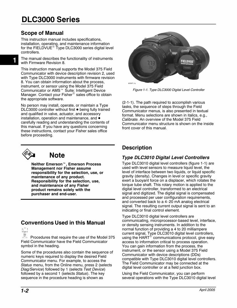
Figure 1-1. Type DLC3000 Digital Level Controller
W7977 / IL
(2-1-1). The path required to accomplish varioustasks, the sequence of steps through the FieldCommunicator menus, is also presented in textualformat. Menu selections are shown in italics, e.g.,Calibrate. An overview of the Model 375 FieldCommunicator menu structure is shown on the insidefront cover of this manual.
Description
Type DLC3010 Digital Level ControllersType DLC3010 digital level controllers (figure 1-1) areused with level sensors to measure liquid level, thelevel of interface between two liquids, or liquid specificgravity (density). Changes in level or specific gravityexert a buoyant force on a displacer, which rotates thetorque tube shaft. This rotary motion is applied to thedigital level controller, transformed to an electricalsignal and digitized. The digital signal is compensatedand processed per user configuration requirements,and converted back to a 4-20 mA analog electricalsignal. The resulting current output signal is sent to anindicating or final control element.
Type DLC3010 digital level controllers arecommunicating, microprocessor-based level, interface,or density sensing instruments. In addition to thenormal function of providing a 4 to 20 milliamperecurrent signal, Type DLC3010 digital level controllers,using the HART� communications protocol, give easyaccess to information critical to process operation.You can gain information from the process, theinstrument, or the sensor using a Model 375 FieldCommunicator with device descriptions (DDs)compatible with Type DLC3010 digital level controllers.The Field Communicator may be connected at thedigital level controller or at a field junction box.
Using the Field Communicator, you can performseveral operations with the Type DLC3010 digital level
1
Introduction
April 2005 1-3
controller. You can interrogate, configure, calibrate, ortest the digital level controller. Using the HARTprotocol, information from the field can be integratedinto control systems or be received on a single loopbasis.
Type DLC3010 digital level controllers are designed todirectly replace standard pneumatic andelectro-pneumatic level transmitters. Type DLC3010digital level controllers mount on a wide variety ofFisher 249 Series cageless and caged level sensors.Type DLC3010 digital level controllers mount on othermanufacturers’ displacer type level sensors throughthe use of mounting adaptors.
249 Series Caged Sensors (see table 1-8)
� The Type 249, 249B, 249BF, 249C, 249K, and249L sensors side-mount on the vessel with thedisplacer mounted inside a cage outside the vessel.(The Type 249BF is available only in Europe, MiddleEast, and Africa.)
249 Series Cageless Sensors (see table 1-9)
� The Type 249BP, 249CP, and 249P sensorstop-mount on the vessel with the displacer hangingdown into the vessel.
� The Type 249V sensor side-mounts on thevessel with the displacer hanging out into the vessel.
� The Type 249W wafer-style sensor mounts ontop of a vessel or on a customer-supplied cage.
Specifications Specifications for the Type DLC3000 digital levelcontrollers are shown in table 1-1. Specifications forthe 249 Series sensor are shown in table 1-5.Specifications for the Field Communicator can befound in the Product Manual for The FieldCommunicator.
Related Documents Other documents containing information related to theType DLC3000 digital level controllers and 249 Seriessensors include:
� FIELDVUE� Type DLC3010 Digital LevelControllers (Bulletin 11.2:DLC3000)
� Proportional Control Loop with FIELDVUE�
Instruments (PS Sheet 62.1:FIELDVUE(E))
� Audio Monitor for HART� Communications (PSSheet 62.1:FIELDVUE (G))
� Using FIELDVUE� Instruments with the SmartHART� Loop Interface and Monitor (HIM) (PS Sheet62.1:FIELDVUE(L))
� Caged 249 Series Displacer Sensors InstructionManual - Form 1802
� Cageless 249 Series Displacer SensorsInstruction Manual - Form 1803
� Type 249W Cageless Wafer Style Level SensorInstruction Manual - Form 5729
� Supplement to 249 Series Sensors InstructionManual: Simulation of Process Conditions forCalibration of Level-Trols - Form 5767
� Technical Monograph 7: The Dynamics of Leveland Pressure Control
� Technical Monograph 18: Level-Trol DensityTransmitter
� Technical Monograph 26: Guidelines for Selectionof Liquid Level Control Equipment
Educational Services For information on available courses for the DLC3000Series digital level controller, as well as a variety ofother products, contact:
Emerson Process ManagementEducational Services, RegistrationP.O. Box 190; 301 S. 1st Ave.Marshalltown, IA 50158-2823Phone: 800-338-8158 orPhone: 641-754-3771 FAX: 641-754-3431e-mail: [email protected]
1
DLC3000 Series
April 20051-4
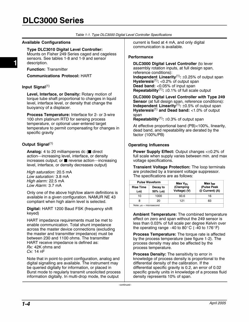
Table 1-1. Type DLC3000 Digital Level Controller Specifications
Available Configurations
Type DLC3010 Digital Level Controller:Mounts on Fisher 249 Series caged and cagelesssensors. See tables 1-8 and 1-9 and sensordescription.
Function: Transmitter
Communications Protocol: HART
Input Signal(1)
Level, Interface, or Density: Rotary motion oftorque tube shaft proportional to changes in liquidlevel, interface level, or density that change thebuoyancy of a displacer.
Process Temperature: Interface for 2- or 3-wire100 ohm platinum RTD for sensing processtemperature, or optional user-entered targettemperature to permit compensating for changes inspecific gravity
Output Signal(1)
Analog: 4 to 20 milliamperes dc (� directaction—increasing level, interface, or densityincreases output; or � reverse action—increasinglevel, interface, or density decreases output)
High saturation: 20.5 mALow saturation: 3.8 mAHigh alarm: 22.5 mALow Alarm: 3.7 mA
Only one of the above high/low alarm definitions isavailable in a given configuration. NAMUR NE 43compliant when high alarm level is selected.
Digital: HART 1200 Baud FSK (frequency shiftkeyed)
HART impedance requirements must be met toenable communication. Total shunt impedanceacross the master device connections (excludingthe master and transmitter impedance) must bebetween 230 and 1100 ohms. The transmitterHART receive impedance is defined as:Rx: 42K ohms and Cx: 14 nF
Note that in point-to-point configuration, analog anddigital signalling are available. The instrument maybe queried digitally for information, or placed inBurst mode to regularly transmit unsolicited processinformation digitally. In multi-drop mode, the output
current is fixed at 4 mA, and only digitalcommunication is available.
Performance
DLC3000 Digital Level Controller (to leverassembly rotation inputs, at full design span,reference conditions):Independent Linearity(1): ±0.25% of output spanHysteresis(1): <0.2% of output spanDead band: <0.05% of input spanRepeatability(1): ±0.1% of full scale output
DLC3000 Digital Level Controller with Type 249Sensor (at full design span, reference conditions):Independent Linearity(1): ±0.5% of output spanHysteresis(1) and Dead band: <1.0% of outputspanRepeatability(1): ±0.3% of output span
At effective proportional band (PB)<100%, linearity,dead band, and repeatability are derated by thefactor (100%/PB)
Operating Influences
Power Supply Effect: Output changes <±0.2% offull scale when supply varies between min. and maxvoltage specifications.
Transient Voltage Protection: The loop terminalsare protected by a transient voltage suppressor.The specifications are as follows:
Pulse Waveform Max VCL Max IPPRise Time
��s)Decay to50% ��s)
Max VCL(Clamping Voltage) (V)
Max IPP(Pulse Peak
@ Current) (A)
10 1000 93.6 16
8 20 121 83Note: µs = microsecond
Ambient Temperature: The combined temperatureeffect on zero and span without the 249 sensor isless than 0.03% of full scale per degree Kelvin overthe operating range -40 to 80�C (-40 to 176�F)
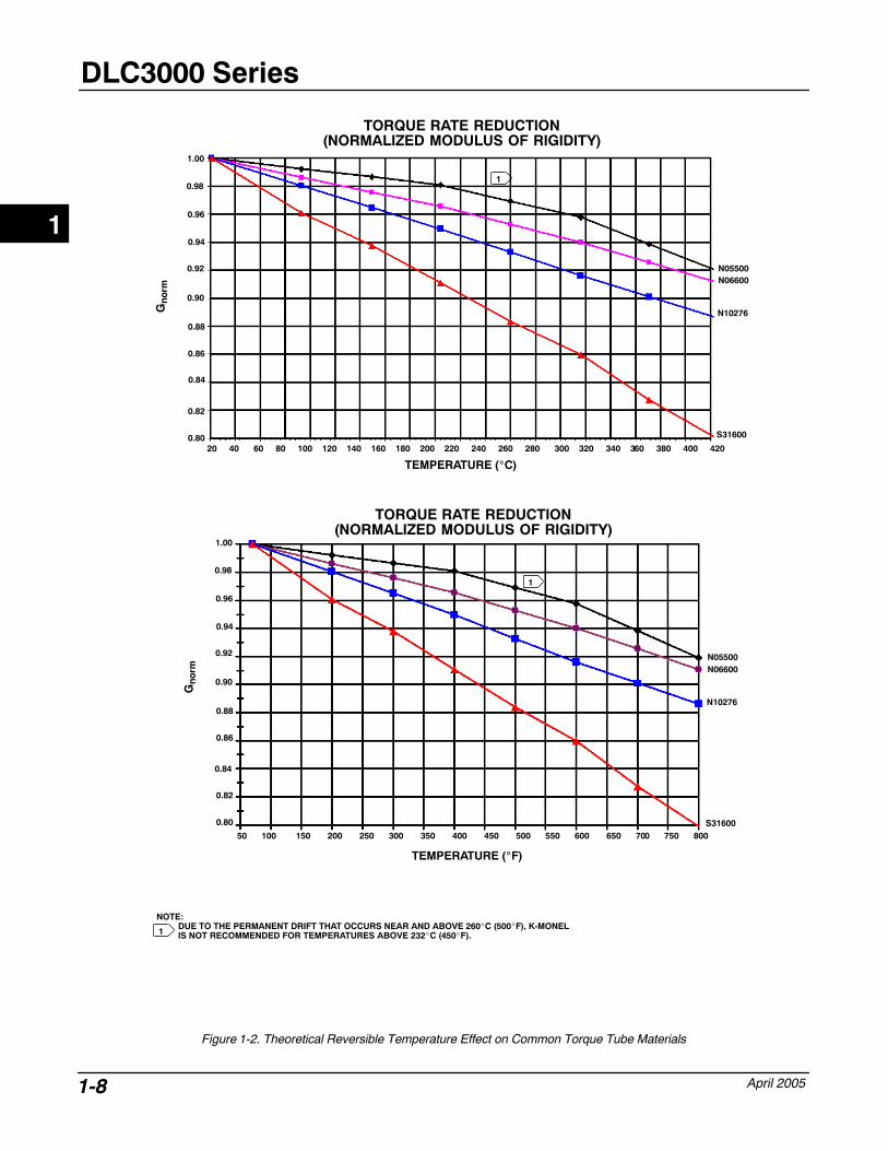
Process Temperature: The torque rate is affectedby the process temperature (see figure 1-2). Theprocess density may also be affected by theprocess temperature.
Process Density: The sensitivity to error inknowledge of process density is proportional to thedifferential density of the calibration. If thedifferential specific gravity is 0.2, an error of 0.02specific gravity units in knowledge of a process fluiddensity represents 10% of span.
-continued -
1
Introduction
April 2005 1-5
Table 1-1. Type DLC3000 Digital Level Controller Specifications (continued)
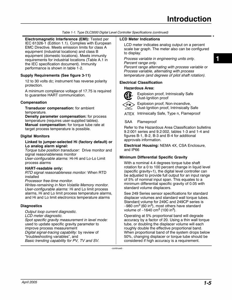
Electromagnetic Interference (EMI): Tested perIEC 61326-1 (Edition 1.1). Complies with EuropeanEMC Directive. Meets emission limits for class Aequipment (industrial locations) and class Bequipment (domestic locations). Meets immunityrequirements for industrial locations (Table A.1 inthe IEC specification document). Immunityperformance is shown in table 1-2.
Supply Requirements (See figure 3-11)
12 to 30 volts dc; instrument has reverse polarityprotection.
A minimum compliance voltage of 17.75 is requiredto guarantee HART communication.
Compensation
Transducer compensation: for ambienttemperature.Density parameter compensation: for processtemperature (requires user-supplied tables).Manual compensation: for torque tube rate attarget process temperature is possible.
Digital Monitors
Linked to jumper-selected Hi (factory default) orLo analog alarm signal:Torque tube position transducer: Drive monitor andsignal reasonableness monitorUser-configurable alarms: Hi-Hi and Lo-Lo Limitprocess alarms
HART-readable only:RTD signal reasonableness monitor: When RTDinstalledProcessor free-time monitor.Writes-remaining in Non Volatile Memory monitor.User-configurable alarms: Hi and Lo limit processalarms, Hi and Lo limit process temperature alarms,and Hi and Lo limit electronics temperature alarms
Diagnostics
Output loop current diagnostic.LCD meter diagnostic.Spot specific gravity measurement in level mode:used to update specific gravity parameter toimprove process measurementDigital signal-tracing capability: by review of“troubleshooting variables”, andBasic trending capability for PV, TV and SV.
LCD Meter Indications
LCD meter indicates analog output on a percentscale bar graph. The meter also can be configuredto display:
Process variable in engineering units only.Percent range only.Percent range alternating with process variable orProcess variable, alternating with processtemperature (and degrees of pilot shaft rotation).
Electrical Classification
Hazardous Area:
Explosion proof, Intrinsically Safe Dust-Ignition proof
Explosion proof, Non-incendive, Dust-Ignition proof, Intrinsically Safe
Intrinsically Safe, Type n, Flameproof
Flameproof
Refer to the Hazardous Area Classification bulletins9.2:001 series and 9.2:002, tables 1-3 and 1-4 andfigures B-1, B-2, B-3 and B-4 for additionalapprovals information.
Electrical Housing: NEMA 4X, CSA Enclosure,and IP66
Minimum Differential Specific Gravity
With a nominal 4.4 degrees torque tube shaftrotation for a 0 to 100 percent change in liquid level(specific gravity=1), the digital level controller canbe adjusted to provide full output for an input rangeof 5% of nominal input span. This equates to aminimum differential specific gravity of 0.05 withstandard volume displacers.
See 249 Series sensor specifications for standarddisplacer volumes and standard wall torque tubes.Standard volume for 249C and 249CP series is∼980 cm3 (60 in3), most others have standardvolume of ∼1640 cm3 (100 in3).
Operating at 5% proportional band will degradeaccuracy by a factor of 20. Using a thin wall torquetube, or doubling the displacer volume will eachroughly double the effective proportional band.When proportional band of the system drops below50%, changing displacer or torque tube should beconsidered if high accuracy is a requirement.
-continued -
1
APPROVED
ATEX
SAA
DLC3000 Series
April 20051-6
Table 1-1. Type DLC3000 Digital Level Controller Specifications (continued)
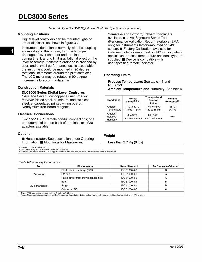
Mounting Positions
Digital level controllers can be mounted right- orleft-of-displacer, as shown in figure 3-7.
Instrument orientation is normally with the couplingaccess door at the bottom, to provide properdrainage of lever chamber and terminalcompartment, and to limit gravitational effect on thelever assembly. If alternate drainage is provided byuser, and a small performance loss is acceptable,the instrument could be mounted in 90 degreerotational increments around the pilot shaft axis.The LCD meter may be rotated in 90 degreeincrements to accommodate this.
Construction Materials
DLC3000 Series Digital Level Controller:Case and Cover: Low-copper aluminum alloyInternal: Plated steel, aluminum, and stainlesssteel; encapsulated printed wiring boards;Neodymium Iron Boron Magnets
Electrical Connections
Two 1/2-14 NPT female conduit connections; oneon bottom and one on back of terminal box. M20adapters available.
Options
� Heat insulator. See description under OrderingInformation. � Mountings for Masoneilan,
Yamatake and Foxboro/Eckhardt displacersavailable. � Level Signature Series Test(Performance Validation Report) available (EMAonly) for instruments factory-mounted on 249sensor. � Factory Calibration: available forinstruments factory-mounted on 249 sensor, whenapplication, process temperature and density(s) aresupplied. � Device is compatible withuser-specified remote indicator.
Operating Limits
Process Temperature: See table 1-6 and figure 3-9.Ambient Temperature and Humidity: See below
Conditions NormalLimits(1,2, 3)
Transport andStorageLimits(1)
NominalReference(1)
AmbientTemperature
-40 to 80�C(-40 to 176�F)
-40 to 85�C(-40 to 185�F)
25�C(77�F)
AmbientRelativeHumidity
0 to 95%,(non-condensing)
0 to 95%,(non-condensing)
40%
Weight
Less than 2.7 Kg (6 lbs)1. Defined in ISA Standard S51.12. LCD meter may not be readable below -20�C ( -4�F)3. Contact your Fisher sales office or application engineer if temperatures exceeding these limits are required.
Table 1-2. Immunity PerformancePort Phenomenon Basic Standard Performance Criteria(1)
Electrostatic discharge (ESD) IEC 61000-4-2 B
Enclosure EM field IEC 61000-4-3 AEnclosureRated power frequency magnetic field IEC 61000-4-8 A
Burst IEC 61000-4-4 B
I/O signal/control Surge IEC 61000-4-5 BI/O signal/controlConducted RF IEC 61000-4-6 A
Note: RTD wiring must be shorter than 3 meters (9.8 feet).1. A = No degradation during testing. B = Temporary degradation during testing, but is self-recovering. Specification Limit = +/ - 1% of span.
1
Introduction
April 2005 1-7
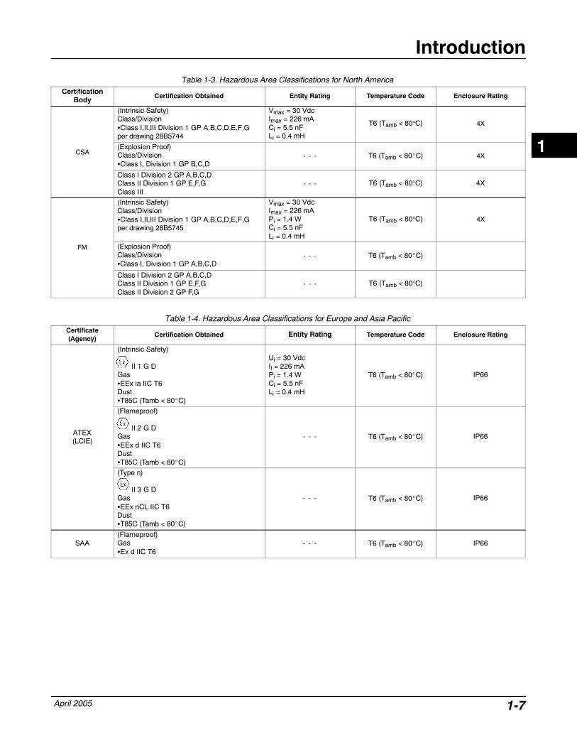
Table 1-3. Hazardous Area Classifications for North AmericaCertification
Body Certification Obtained Entity Rating Temperature Code Enclosure Rating
(Intrinsic Safety)Class/Division�Class I,II,III Division 1 GP A,B,C,D,E,F,Gper drawing 28B5744
Vmax = 30 VdcImax = 226 mACi = 5.5 nFLi = 0.4 mH
T6 (Tamb < 80°C) 4X
CSA(Explosion Proof)Class/Division�Class I, Division 1 GP B,C,D
- - - T6 (Tamb < 80�C) 4X
Class I Division 2 GP A,B,C,DClass II Division 1 GP E,F,GClass III
- - - T6 (Tamb < 80°C) 4X
(Intrinsic Safety)Class/Division�Class I,II,III Division 1 GP A,B,C,D,E,F,Gper drawing 28B5745
Vmax = 30 VdcImax = 226 mAPi = 1.4 WCi = 5.5 nFLi = 0.4 mH
T6 (Tamb < 80°C) 4X
FM (Explosion Proof)Class/Division�Class I, Division 1 GP A,B,C,D
- - - T6 (Tamb < 80�C)
Class I Division 2 GP A,B,C,DClass II Division 1 GP E,F,GClass II Division 2 GP F,G
- - - T6 (Tamb < 80°C)
Table 1-4. Hazardous Area Classifications for Europe and Asia PacificCertificate(Agency)
Certification Obtained Entity Rating Temperature Code Enclosure Rating
(Intrinsic Safety)
II 1 G DGas�EEx ia IIC T6Dust�T85C (Tamb < 80�C)
Ui = 30 VdcIi = 226 mAPi = 1.4 WCi = 5.5 nFLi = 0.4 mH
T6 (Tamb < 80�C) IP66
ATEX(LCIE)
(Flameproof)
II 2 G DGas�EEx d IIC T6Dust�T85C (Tamb < 80�C)
- - - T6 (Tamb < 80�C) IP66
(Type n)
II 3 G DGas�EEx nCL IIC T6Dust�T85C (Tamb < 80�C)
- - - T6 (Tamb < 80�C) IP66
SAA(Flameproof)Gas�Ex d IIC T6
- - - T6 (Tamb < 80�C) IP66
1
DLC3000 Series
April 20051-8
TORQUE RATE REDUCTION(NORMALIZED MODULUS OF RIGIDITY)
Gno
rm
TEMPERATURE (�C)
N05500N06600
N10276
S31600
20 40 60 80 100 120 140 160 180 200 220 240 260 280 300 320 340 360 380 400 420
1.00
0.96
0.92
0.88
0.84
0.82
0.80
0.90
0.86
0.98
0.94
TORQUE RATE REDUCTION(NORMALIZED MODULUS OF RIGIDITY)
TEMPERATURE (�F)
N05500N06600
N10276
S3160050 100 150 200 250 300 350 400 450 500 550 600 650 700 750 800
1.00
0.96
0.92
0.88
0.84
0.82
0.80
0.90
0.86
0.98
0.94
Gno
rm
NOTE: DUE TO THE PERMANENT DRIFT THAT OCCURS NEAR AND ABOVE 260�C (500�F), K-MONELIS NOT RECOMMENDED FOR TEMPERATURES ABOVE 232�C (450�F).
1
1
1
Figure 1-2. Theoretical Reversible Temperature Effect on Common Torque Tube Materials
1
Introduction
April 2005 1-9
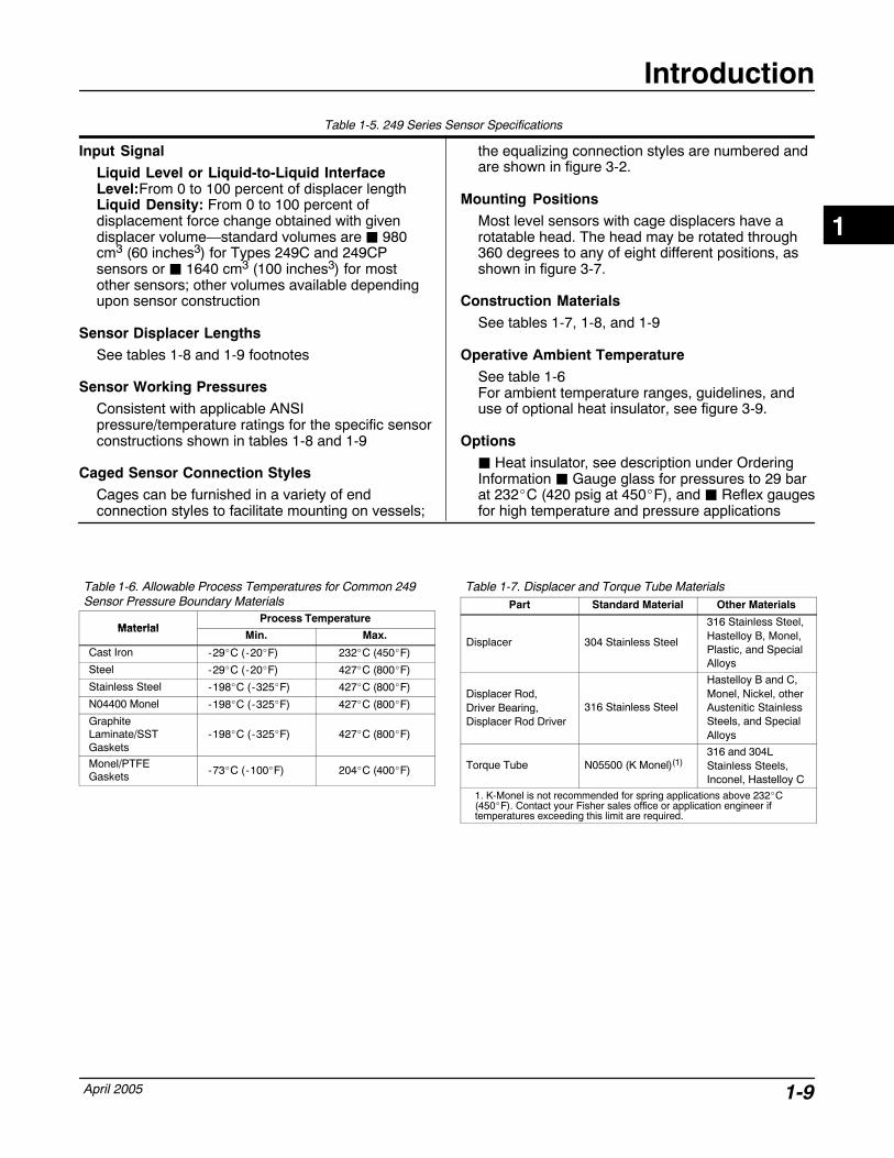
Table 1-5. 249 Series Sensor Specifications
Input Signal
Liquid Level or Liquid-to-Liquid InterfaceLevel:From 0 to 100 percent of displacer lengthLiquid Density: From 0 to 100 percent ofdisplacement force change obtained with givendisplacer volume—standard volumes are � 980cm3 (60 inches3) for Types 249C and 249CPsensors or � 1640 cm3 (100 inches3) for mostother sensors; other volumes available dependingupon sensor construction
Sensor Displacer Lengths
See tables 1-8 and 1-9 footnotes
Sensor Working Pressures
Consistent with applicable ANSIpressure/temperature ratings for the specific sensorconstructions shown in tables 1-8 and 1-9
Caged Sensor Connection Styles
Cages can be furnished in a variety of endconnection styles to facilitate mounting on vessels;
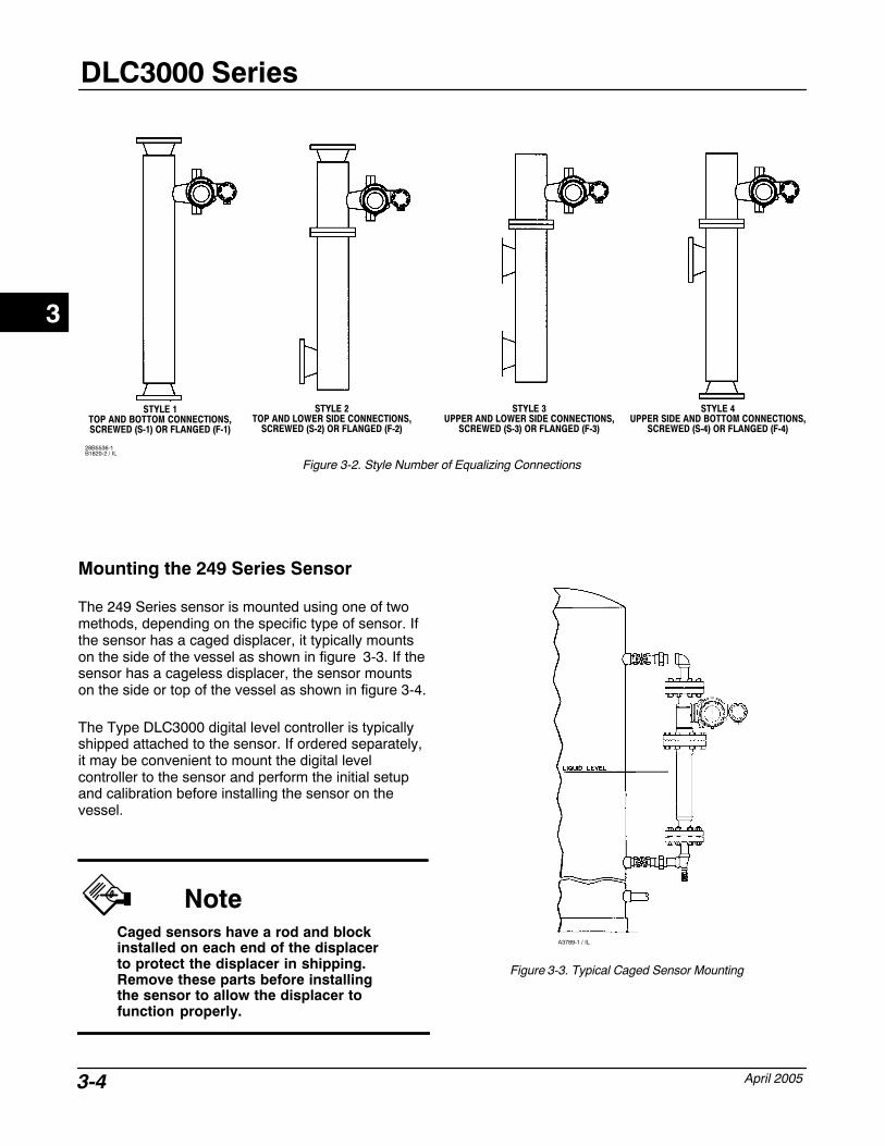
the equalizing connection styles are numbered andare shown in figure 3-2.
Mounting Positions
Most level sensors with cage displacers have arotatable head. The head may be rotated through360 degrees to any of eight different positions, asshown in figure 3-7.
Construction Materials
See tables 1-7, 1-8, and 1-9
Operative Ambient Temperature
See table 1-6For ambient temperature ranges, guidelines, anduse of optional heat insulator, see figure 3-9.
Options
� Heat insulator, see description under OrderingInformation � Gauge glass for pressures to 29 barat 232�C (420 psig at 450�F), and � Reflex gaugesfor high temperature and pressure applications
Table 1-6. Allowable Process Temperatures for Common 249Sensor Pressure Boundary Materials
MaterialProcess Temperature
MaterialMin. Max.
Cast Iron -29�C (-20�F) 232�C (450�F)
Steel -29�C (-20�F) 427�C (800�F)
Stainless Steel -198�C (-325�F) 427�C (800�F)
N04400 Monel -198�C (-325�F) 427�C (800�F)
GraphiteLaminate/SSTGaskets
-198�C (-325�F) 427�C (800�F)
Monel/PTFEGaskets -73�C (-100�F) 204�C (400�F)
Table 1-7. Displacer and Torque Tube MaterialsPart Standard Material Other Materials
Displacer 304 Stainless Steel
316 Stainless Steel,Hastelloy B, Monel,Plastic, and SpecialAlloys
Displacer Rod,Driver Bearing,Displacer Rod Driver
316 Stainless Steel
Hastelloy B and C,Monel, Nickel, otherAustenitic StainlessSteels, and SpecialAlloys
Torque Tube N05500 (K Monel)(1)316 and 304LStainless Steels,Inconel, Hastelloy C
1. K-Monel is not recommended for spring applications above 232�C(450�F). Contact your Fisher sales office or application engineer iftemperatures exceeding this limit are required.
1
DLC3000 Series
April 20051-10
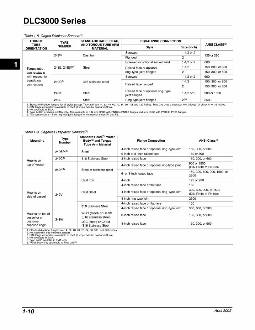
Table 1-8. Caged Displacer Sensors(1)
TORQUETUBE
TYPE STANDARD CAGE, HEAD,AND TORQUE TUBE ARM
EQUALIZING CONNECTIONANSI CLASS(2)TUBE
ORIENTATION
TYPENUMBER AND TORQUE TUBE ARM
MATERIAL Style Size (Inch)ANSI CLASS(2)
249(3) Cast ironScrewed 1-1/2 or 2
125 or 250249(3) Cast ironFlanged 2
125 or 250
Screwed or optional socket weld 1-1/2 or 2 600
Torque tube 249B, 249BF(4) Steel Raised face or optional 1-1/2 150, 300, or 600Torque tubearm rotatable
249B, 249BF Steel Raised face or optionalring-type-joint flanged 2 150, 300, or 600arm rotatable
with respect toli i
Screwed 1-1/2 or 2 600pequalizingconnections
249C(3) 316 stainless steelRaised face flanged
1-1/2 150, 300, or 600connections
249C 316 stainless steelRaised face flanged
2 150, 300, or 600
249K SteelRaised face or optional ring-typejoint flanged
1-1/2 or 2 900 or 1500
249L Steel Ring-type joint flanged 2(5) 25001. Standard displacer lengths for all styles (except Type 249) are 14, 32, 48, 60, 72, 84, 96, 108 and 120 inches. Type 249 uses a displacer with a length of either 14 or 32 inches.2. DIN flange connections available in EMA (Europe, Middle East and Africa).3. Not available in EMA.4. Type 249BF available in EMA only. Also available in DIN size DN40 with PN10 to PN100 flanges and size DN50 with PN10 to PN63 flanges.5. Top connection is 1-inch ring-type joint flanged for connection styles F1 and F2.
Table 1-9. Cageless Displacer Sensors(1)
Mounting TypeNumber
Standard Head(2), WaferBody(6) and TorqueTube Arm Material
Flange Connection ANSI Class(3)
249BP(4) Steel4-inch raised face or optional ring-type joint 150, 300, or 600
249BP(4) Steel6-inch or 8-inch raised face 150 or 300
Mounts on249CP 316 Stainless Steel 3-inch raised face 150, 300, or 600
Mounts ontop of vessel
249P(5) Steel or stainless steel
4-inch raised face or optional ring-type joint 900 or 1500(DIN PN10 to PN250)
249P(5) Steel or stainless steel6- or 8-inch raised face 150, 300, 600, 900, 1500, or
2500
Cast Iron 4-inch 125 or 250
4-inch raised face or flat face 150
Mounts on side of vessel
249VCast Steel 4-inch raised face or optional ring-type joint
300, 600, 900, or 1500(DIN PN10 to PN160)
side of vessel249V
4-inch ring-type joint 2500
316 Stainless Steel4-inch raised face or flat face 150
316 Stainless Steel4-inch raised face or optional ring-type joint 300, 600, or 900
Mounts on top ofvessel or on
249W
WCC (steel) or CF8M(316 stainless steel)
3-inch raised face 150, 300, or 600vessel or oncustomersupplied cage
249WLCC (steel) or CF8M(316 Stainless Steel
4-inch raised face 150, 300, or 600
1. Standard displacer lengths are 14, 32, 48, 60, 72, 84, 96, 108, and 120 inches.2. Not used with side-mounted sensors.3. DIN flange connections available in EMA (Europe, Middle East and Africa).4. Not available in EMA.5. Type 249P available in EMA only.6. Wafer Body only applicable to Type 249W.
1
Principle of Operation
April 2005 2-1
2-2
Section 2 Principle of Operation
HART� Communication 2-2. . . . . . . . . . . . . . . . . . . . . . . . . . . . . . . . . . . . . . . . . . . . . . . .
Digital Level Controller Operation 2-2. . . . . . . . . . . . . . . . . . . . . . . . . . . . . . . . . . . . .
2
DLC3000 Series
April 20052-2
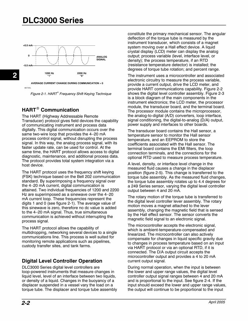
Figure 2-1. HART� Frequency Shift Keying Technique
-0.5 mA
+0.5 mA
1200 Hz“1”
2200 Hz“0”
AVERAGE CURRENT CHANGE DURING COMMUNICATION = 0
ANALOGSIGNAL
0
A6174/IL
HART� Communication The HART (Highway Addressable RemoteTransducer) protocol gives field devices the capabilityof communicating instrument and process datadigitally. This digital communication occurs over thesame two-wire loop that provides the 4–20 mAprocess control signal, without disrupting the processsignal. In this way, the analog process signal, with itsfaster update rate, can be used for control. At thesame time, the HART protocol allows access to digitaldiagnostic, maintenance, and additional process data.The protocol provides total system integration via ahost device.
The HART protocol uses the frequency shift keying(FSK) technique based on the Bell 202 communicationstandard. By superimposing a frequency signal overthe 4–20 mA current, digital communication isattained. Two individual frequencies of 1200 and 2200Hz are superimposed as a sinewave over the 4–20mA current loop. These frequencies represent thedigits 1 and 0 (see figure 2-1). The average value ofthis sinewave is zero, therefore no dc value is addedto the 4–20 mA signal. Thus, true simultaneouscommunication is achieved without interrupting theprocess signal.
The HART protocol allows the capability ofmultidropping, networking several devices to a singlecommunications line. This process is well suited formonitoring remote applications such as pipelines,custody transfer sites, and tank farms.
Digital Level Controller Operation DLC3000 Series digital level controllers areloop-powered instruments that measure changes inliquid level, level of an interface between two liquids,or density of a liquid. Changes in the buoyancy of adisplacer suspended in a vessel vary the load on atorque tube. The displacer and torque tube assembly
constitute the primary mechanical sensor. The angulardeflection of the torque tube is measured by theinstrument transducer, which consists of a magnetsystem moving over a Hall effect device. A liquidcrystal display (LCD) meter can display the analogoutput; process variable (level, interface level, ordensity); the process temperature, if an RTD(resistance temperature detector) is installed; thedegrees of torque tube rotation; and percent range.
The instrument uses a microcontroller and associatedelectronic circuitry to measure the process variable,provide a current output, drive the LCD meter, andprovide HART communications capability. Figure 2-2shows the digital level controller assembly. Figure 2-3is a block diagram of the main components in theinstrument electronics; the LCD meter, the processormodule, the transducer board, and the terminal board.The processor module contains the microprocessor,the analog-to-digital (A/D) converters, loop interface,signal conditioning, the digital-to-analog (D/A) output,power supply and interfaces to other boards.
The transducer board contains the Hall sensor, atemperature sensor to monitor the Hall sensortemperature, and an EEPROM to store thecoefficients associated with the Hall sensor. Theterminal board contains the EMI filters, the loopconnection terminals, and the connections for theoptional RTD used to measure process temperature.
A level, density, or interface level change in themeasured fluid causes a change in the displacerposition (figure 2-5). This change is transferred to thetorque tube assembly. As the measured fluid changes,the torque tube assembly rotates up to 4.4 degrees fora 249 Series sensor, varying the digital level controlleroutput between 4 and 20 mA.
The rotary motion of the torque tube is transferred tothe digital level controller lever assembly. The rotarymotion moves a magnet attached to the leverassembly, changing the magnetic field that is sensedby the Hall effect sensor. The sensor converts themagnetic field signal to an electronic signal.
The microcontroller accepts the electronic signal,which is ambient-temperature-compensated andlinearized. The microcontroller can also activelycompensate for changes in liquid specific gravity dueto changes in process temperature based on an inputvia HART protocol or via an optional RTD, if it isconnected. The D/A output circuit accepts themicrocontroller output and provides a 4 to 20 mAcurrent output signal.
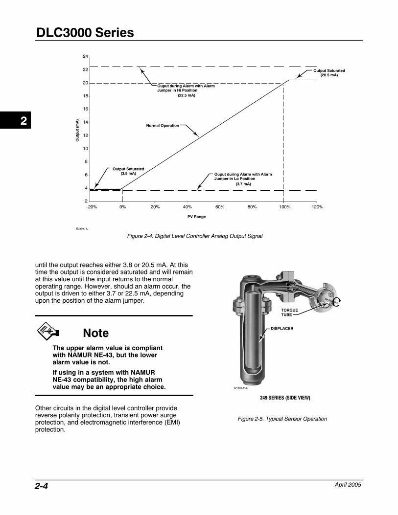
During normal operation, when the input is betweenthe lower and upper range values, the digital levelcontroller output signal ranges between 4 and 20 mAand is proportional to the input. See figure 2-4. If theinput should exceed the lower and upper range values,the output will continue to be proportional to the input
2

Principle of Operation
April 2005 2-3
Figure 2-2. DLC3000 Series Digital Level Controller Assembly
LCD METERASSEMBLY
ELECTRONICSASSEMBLY
LEVER ASSEMBLY
TERMINAL BOX
TERMINAL BOX COVER
HOUSING
COVER
ADAPTER RING
TRANSDUCERBOARD
E0377 / IL
Figure 2-3. DLC3000 Series Digital Level Controller Principle of Operation
LCD Meter
Transducer Module
ProcessorModule
Torque TubeRotation
Linearization Dataresident in NVM
TerminalBox
RTDProcess
TemperatureInterface
Loop / HARTInterface
ElectronicsTemperature Sensor
Shaft PositionTransducer
E0378 / IL
2
DLC3000 Series
April 20052-4
Figure 2-4. Digital Level Controller Analog Output Signal
2
4
6
8
10
12
14
16
18
20
22
24
-20% 0% 20% 40% 60% 80% 100% 120%
Ouput during Alarm with AlarmJumper in Hi Position
Output Saturated(3.8 mA)
(22.5 mA)
Ouput during Alarm with AlarmJumper in Lo Position
(3.7 mA)
Output Saturated(20.5 mA)
Normal Operation
Ou
tpu
t (m
A)
PV Range
E0379 / IL
until the output reaches either 3.8 or 20.5 mA. At thistime the output is considered saturated and will remainat this value until the input returns to the normaloperating range. However, should an alarm occur, theoutput is driven to either 3.7 or 22.5 mA, dependingupon the position of the alarm jumper.
NoteThe upper alarm value is compliantwith NAMUR NE-43, but the loweralarm value is not.
If using in a system with NAMURNE-43 compatibility, the high alarmvalue may be an appropriate choice.
Other circuits in the digital level controller providereverse polarity protection, transient power surgeprotection, and electromagnetic interference (EMI)protection.
Figure 2-5. Typical Sensor Operation
TORQUETUBE
DISPLACER
249 SERIES (SIDE VIEW)
W1389-1*/IL
2
Installation
April 2005 3-1
3-3
Section 3 Installation
Configuration: On the Bench or in the Loop 3-2. . . . . . . . . . . . . . . . . . . . . . . . . .
Protecting the Coupling and Flexures 3-2. . . . . . . . . . . . . . . . . . . . . . . . . . . . . . . . .
Mounting 3-2. . . . . . . . . . . . . . . . . . . . . . . . . . . . . . . . . . . . . . . . . . . . . . . . . . . . . . . . . . . . . . . .
Mounting the 249 Series Sensor 3-4. . . . . . . . . . . . . . . . . . . . . . . . . . . . . . . . . . . . . . . . . .
Digital Level Controller Orientation 3-5. . . . . . . . . . . . . . . . . . . . . . . . . . . . . . . . . . . . . . . .
Mounting the Digital Level Controller on a 249 Series Sensor 3-5. . . . . . . . . . . . . .
Mounting the Digital Level Controller for High Temperature Applications 3-6. . .
Electrical Connections 3-8. . . . . . . . . . . . . . . . . . . . . . . . . . . . . . . . . . . . . . . . . . . . . . . . .
Power Supply 3-8. . . . . . . . . . . . . . . . . . . . . . . . . . . . . . . . . . . . . . . . . . . . . . . . . . . . . . . . . . . .
Field Wiring 3-9. . . . . . . . . . . . . . . . . . . . . . . . . . . . . . . . . . . . . . . . . . . . . . . . . . . . . . . . . . . . . .
Grounding 3-10. . . . . . . . . . . . . . . . . . . . . . . . . . . . . . . . . . . . . . . . . . . . . . . . . . . . . . . . . . . . . . . Shielded Wire 3-10. . . . . . . . . . . . . . . . . . . . . . . . . . . . . . . . . . . . . . . . . . . . . . . . . . . . . . . . . . .
Power/Current Loop Connections 3-10. . . . . . . . . . . . . . . . . . . . . . . . . . . . . . . . . . . . . . . .
RTD Connections 3-10. . . . . . . . . . . . . . . . . . . . . . . . . . . . . . . . . . . . . . . . . . . . . . . . . . . . . . . . Two-Wire RTD Connections 3-10. . . . . . . . . . . . . . . . . . . . . . . . . . . . . . . . . . . . . . . . . . . . . . . Three-Wire RTD Connections 3-10. . . . . . . . . . . . . . . . . . . . . . . . . . . . . . . . . . . . . . . . . . . . . .
Communication Connections 3-10. . . . . . . . . . . . . . . . . . . . . . . . . . . . . . . . . . . . . . . . . . . . .
Test Connections 3-11. . . . . . . . . . . . . . . . . . . . . . . . . . . . . . . . . . . . . . . . . . . . . . . . . . . . . . . .
Multichannel Installations 3-11. . . . . . . . . . . . . . . . . . . . . . . . . . . . . . . . . . . . . . . . . . . . . . . .
Alarm Jumper 3-12. . . . . . . . . . . . . . . . . . . . . . . . . . . . . . . . . . . . . . . . . . . . . . . . . . . . . . . . . . .
Changing Jumper Position 3-12. . . . . . . . . . . . . . . . . . . . . . . . . . . . . . . . . . . . . . . . . . . . . . .
Loop Test 3-12. . . . . . . . . . . . . . . . . . . . . . . . . . . . . . . . . . . . . . . . . . . . . . . . . . . . . . . . . . . . . . . .
Installation in Conjunction with a RosemountModel 333 HART� Tri-Loop� HART�-to-AnalogSignal Converter 3-13. . . . . . . . . . . . . . . . . . . . . . . . . . . . . . . . . . . . . . . . . . . . . . . . . . . . . . .
3
DLC3000 Series
April 20053-2
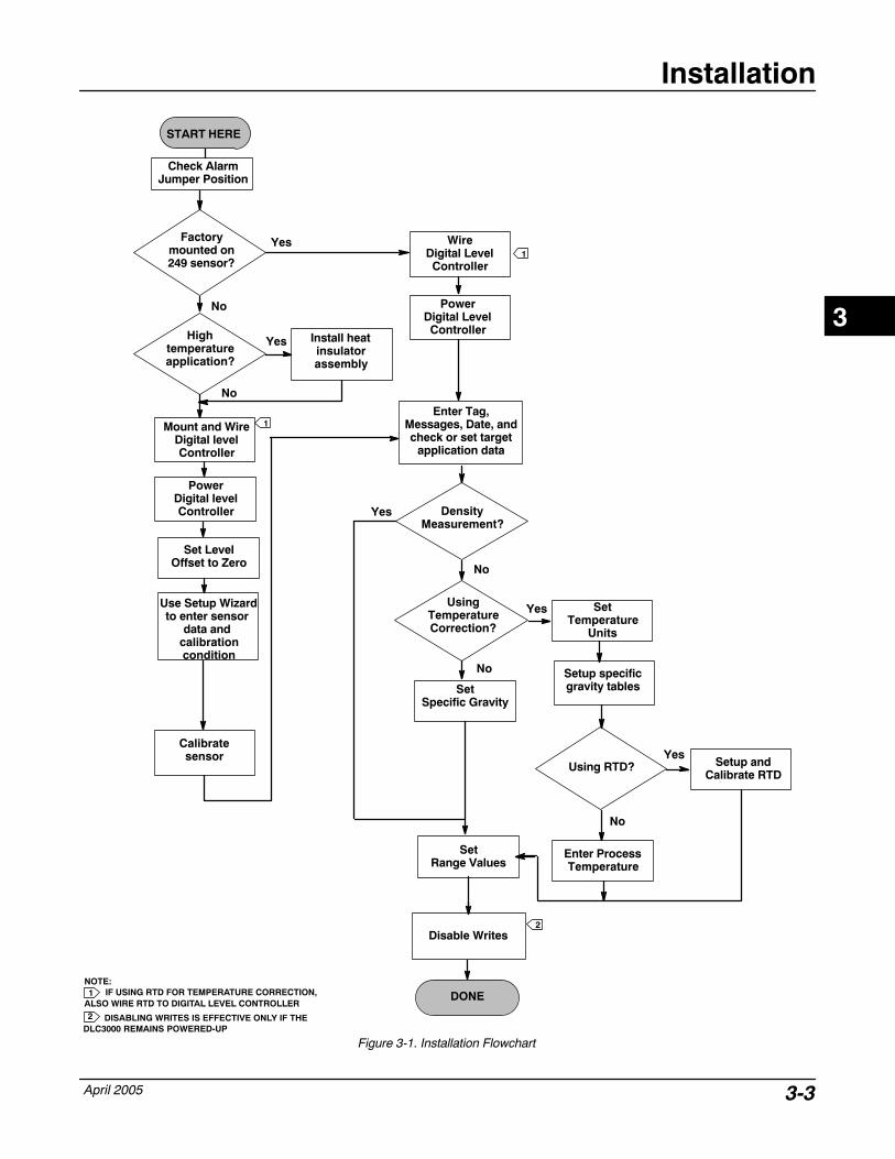
This section contains digital level controller installationinformation including an installation flowchart (figure3-1), mounting and electrical installation information,and a discussion of failure mode jumpers.
Configuration: On the Bench or inthe LoopConfigure the digital level controller before or afterinstallation. It may be useful to configure theinstrument on the bench before installation to ensureproper operation, and to familiarize yourself with itsfunctionality.
Protecting the Coupling andFlexures
CAUTION
Damage to flexures and other partscan cause measurement errors.Observe the following steps beforemoving the sensor and controller.
Lever Lock
The lever lock is built in to the coupling access door.When the door is open, it positions the lever in theneutral travel position for coupling. In some cases, thisfunction is used to protect the lever assembly fromviolent motion during shipment.
A DLC3010 controller will have one of the followingmechanical configurations when received:
1. A fully assembled and coupled caged-displacersystem is shipped with the displacer or driver rodblocked within the operating range by mechanicalmeans. In this case, the access handle (figure 3-5) willbe in the unlocked position. Remove thedisplacer-blocking hardware before calibration. (Seethe appropriate sensor instruction manual). Thecoupling should be intact.
CAUTION
When shipping an instrument mountedon a sensor, if the lever assembly iscoupled to the linkage, and the linkageis constrained by the displacer blocks,use of the lever lock may result indamage to bellows joints or flexure.
2. If the displacer cannot be blocked because of cageconfiguration or other concerns, the transmitter isuncoupled from the torque tube by loosening thecoupling nut, and the access handle will be in thelocked position. Before placing such a configurationinto service, perform the Coupling procedure.
3. For a cageless system where the displacer is notconnected to the torque tube during shipping, thetorque tube itself stabilizes the coupled lever positionby resting against a physical stop in the sensor. Theaccess handle will be in the unlocked position. Mountthe sensor and hang the displacer. The couplingshould be intact.
4. If the controller was shipped alone, the accesshandle will be in the locked position. All of theMounting, Coupling and Calibration procedures mustbe performed.
The access handle includes a retaining set screw, asshown in figures 3-5 and 3-6. The screw is driven in tocontact the spring plate in the handle assembly beforeshipping. It secures the handle in the desired positionduring shipping and operation. To open or close theaccess door, this set screw must be backed out sothat its top is flush with the handle surface.
Mounting
WARNING
To avoid personal injury, always wearprotective gloves, clothing, andeyewear when performing anyinstallation operations.
Personal injury or property damagedue to sudden release of pressure,contact with hazardous fluid, fire, orexplosion can be caused bypuncturing, heating, or repairing adisplacer that is retaining processpressure or fluid. This danger may notbe readily apparent whendisassembling the sensor orremoving the displacer. Beforedisassembling the sensor orremoving the displacer, observe theappropriate warnings provided in thesensor instruction manual.
Check with your process or safetyengineer for any additional measuresthat must be taken to protect againstprocess media.
3
Installation
April 2005 3-3
Figure 3-1. Installation Flowchart
START HERE
Factorymounted on249 sensor?
Use Setup Wizardto enter sensor
data and calibrationcondition
Check AlarmJumper Position
Mount and WireDigital levelController
PowerDigital levelController
No
Yes
Install heatinsulatorassembly
Hightemperatureapplication?
Yes
No
Set LevelOffset to Zero
Calibratesensor
WireDigital LevelController
PowerDigital LevelController
Enter Tag,Messages, Date, andcheck or set target
application data
DensityMeasurement?
SetRange Values
UsingTemperatureCorrection?
SetTemperature
Units
Setup specificgravity tablesSet
Specific Gravity
Yes
No
Yes
No
Using RTD?Yes
Setup andCalibrate RTD
Enter ProcessTemperature
No
1
1
1
DONE
Disable Writes
NOTE:IF USING RTD FOR TEMPERATURE CORRECTION,
ALSO WIRE RTD TO DIGITAL LEVEL CONTROLLER2
2
DISABLING WRITES IS EFFECTIVE ONLY IF THEDLC3000 REMAINS POWERED-UP
3
DLC3000 Series
April 20053-4
Figure 3-2. Style Number of Equalizing Connections
STYLE 1TOP AND BOTTOM CONNECTIONS,SCREWED (S−1) OR FLANGED (F−1)
STYLE 2TOP AND LOWER SIDE CONNECTIONS,
SCREWED (S−2) OR FLANGED (F−2)
STYLE 3UPPER AND LOWER SIDE CONNECTIONS,
SCREWED (S−3) OR FLANGED (F−3)
STYLE 4UPPER SIDE AND BOTTOM CONNECTIONS,
SCREWED (S−4) OR FLANGED (F−4)
28B5536-1B1820-2 / IL
Mounting the 249 Series Sensor
The 249 Series sensor is mounted using one of twomethods, depending on the specific type of sensor. Ifthe sensor has a caged displacer, it typically mountson the side of the vessel as shown in figure 3-3. If thesensor has a cageless displacer, the sensor mountson the side or top of the vessel as shown in figure 3-4.
The Type DLC3000 digital level controller is typicallyshipped attached to the sensor. If ordered separately,it may be convenient to mount the digital levelcontroller to the sensor and perform the initial setupand calibration before installing the sensor on thevessel.
NoteCaged sensors have a rod and blockinstalled on each end of the displacerto protect the displacer in shipping.Remove these parts before installingthe sensor to allow the displacer tofunction properly.
Figure 3-3. Typical Caged Sensor Mounting
A3789-1 / IL
3
Installation
April 2005 3-5
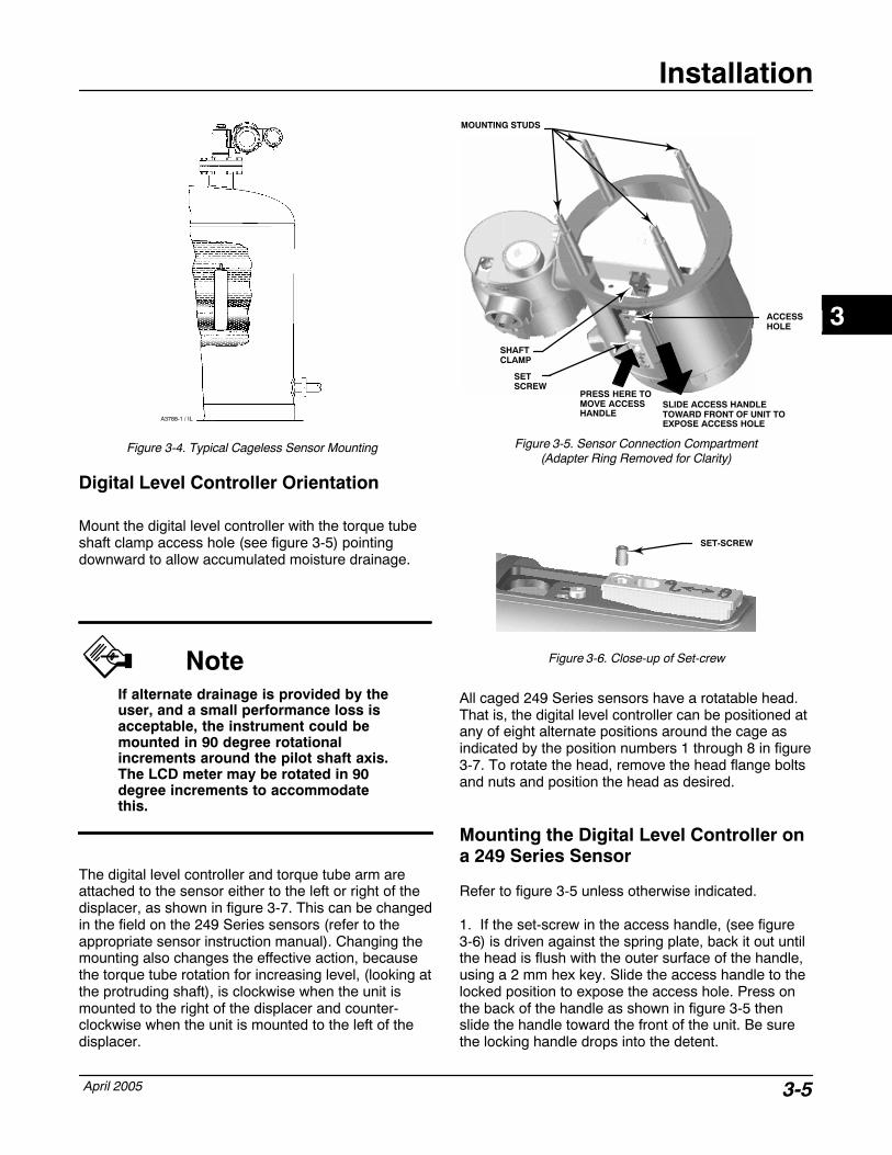
Figure 3-4. Typical Cageless Sensor Mounting
A3788-1 / IL
Digital Level Controller Orientation
Mount the digital level controller with the torque tubeshaft clamp access hole (see figure 3-5) pointingdownward to allow accumulated moisture drainage.
NoteIf alternate drainage is provided by theuser, and a small performance loss isacceptable, the instrument could bemounted in 90 degree rotationalincrements around the pilot shaft axis.The LCD meter may be rotated in 90degree increments to accommodatethis.
The digital level controller and torque tube arm areattached to the sensor either to the left or right of thedisplacer, as shown in figure 3-7. This can be changedin the field on the 249 Series sensors (refer to theappropriate sensor instruction manual). Changing themounting also changes the effective action, becausethe torque tube rotation for increasing level, (looking atthe protruding shaft), is clockwise when the unit ismounted to the right of the displacer and counter-clockwise when the unit is mounted to the left of thedisplacer.
Figure 3-5. Sensor Connection Compartment(Adapter Ring Removed for Clarity)
PRESS HERE TOMOVE ACCESSHANDLE
SLIDE ACCESS HANDLETOWARD FRONT OF UNIT TOEXPOSE ACCESS HOLE
ACCESSHOLE
MOUNTING STUDS
SHAFTCLAMP
SETSCREW
Figure 3-6. Close-up of Set-crew
SET-SCREW
All caged 249 Series sensors have a rotatable head.That is, the digital level controller can be positioned atany of eight alternate positions around the cage asindicated by the position numbers 1 through 8 in figure3-7. To rotate the head, remove the head flange boltsand nuts and position the head as desired.
Mounting the Digital Level Controller ona 249 Series Sensor
Refer to figure 3-5 unless otherwise indicated.
1. If the set-screw in the access handle, (see figure3-6) is driven against the spring plate, back it out untilthe head is flush with the outer surface of the handle,using a 2 mm hex key. Slide the access handle to thelocked position to expose the access hole. Press onthe back of the handle as shown in figure 3-5 thenslide the handle toward the front of the unit. Be surethe locking handle drops into the detent.
3
DLC3000 Series
April 20053-6
8
24
6
3
7
1
5
SENSOR
CAGED
CAGELESS
RIGHT-OF-DISPLACERLEFT-OF-DISPLACER
1 1
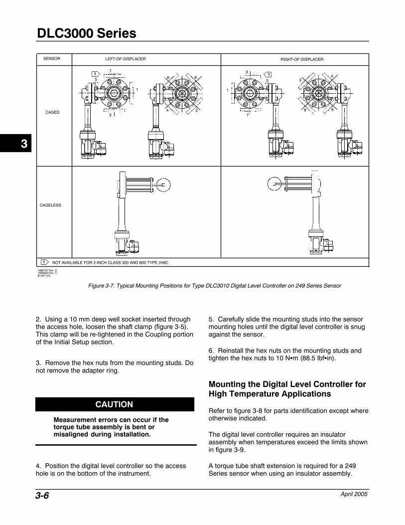
1 NOT AVAILABLE FOR 2-INCH CLASS 300 AND 600 TYPE 249C.
19B2787 Rev. D19B6600 Rev. CB1407-2/IL
8
24
6
1
3
7
5
Figure 3-7. Typical Mounting Positions for Type DLC3010 Digital Level Controller on 249 Series Sensor
2. Using a 10 mm deep well socket inserted throughthe access hole, loosen the shaft clamp (figure 3-5).This clamp will be re-tightened in the Coupling portionof the Initial Setup section.
3. Remove the hex nuts from the mounting studs. Donot remove the adapter ring.
CAUTION
Measurement errors can occur if thetorque tube assembly is bent ormisaligned during installation.
4. Position the digital level controller so the accesshole is on the bottom of the instrument.
5. Carefully slide the mounting studs into the sensormounting holes until the digital level controller is snugagainst the sensor.
6. Reinstall the hex nuts on the mounting studs andtighten the hex nuts to 10 N�m (88.5 lbf�in).
Mounting the Digital Level Controller forHigh Temperature Applications
Refer to figure 3-8 for parts identification except whereotherwise indicated.
The digital level controller requires an insulatorassembly when temperatures exceed the limits shownin figure 3-9.
A torque tube shaft extension is required for a 249Series sensor when using an insulator assembly.
3
Installation
April 2005 3-7
MN2880020A7423-CB2707 / IL
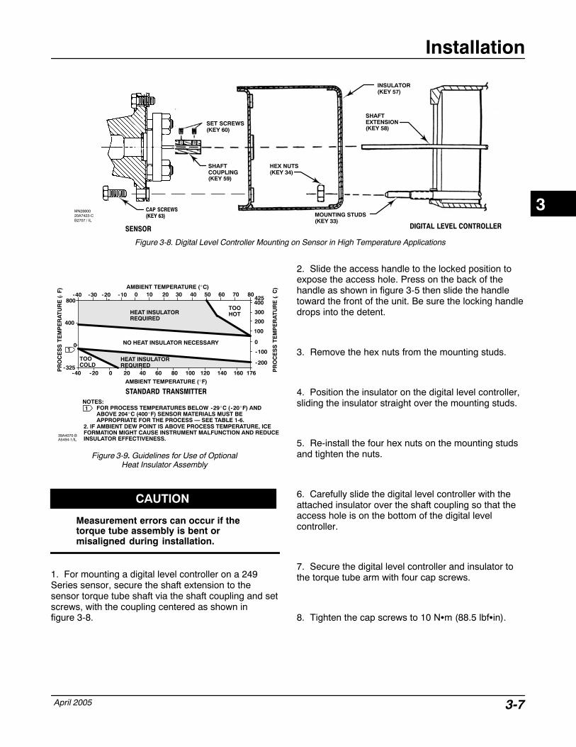
Figure 3-8. Digital Level Controller Mounting on Sensor in High Temperature Applications
SENSOR DIGITAL LEVEL CONTROLLER
SHAFTEXTENSION(KEY 58)
SHAFTCOUPLING(KEY 59)
SET SCREWS(KEY 60)
INSULATOR(KEY 57)
CAP SCREWS(KEY 63) MOUNTING STUDS
(KEY 33)
HEX NUTS(KEY 34)
HEAT INSULATORREQUIRED
Figure 3-9. Guidelines for Use of OptionalHeat Insulator Assembly
70
0 20 40 60 80 100 120 140 160
0 10 20-20 -10 30 40 50 60400
300
200
100
00
400
800
-325
AMBIENT TEMPERATURE (�C)
STANDARD TRANSMITTER
AMBIENT TEMPERATURE (�F)
HEAT INSULATORREQUIRED
TOOHOT
NOTES: FOR PROCESS TEMPERATURES BELOW -29�C ( -20�F) ANDABOVE 204�C (400�F) SENSOR MATERIALS MUST BE APPROPRIATE FOR THE PROCESS — SEE TABLE 1-6.
PR
OC
ES
S T
EM
PE
RA
TU
RE
( C
)
�
PR
OC
ES
S T
EM
PE
RA
TU
RE
( F
)
�
39A4070-BA5494-1/IL
42580
-100
-200
176-20-40
-40 -30
TOOCOLD
1
1
2. IF AMBIENT DEW POINT IS ABOVE PROCESS TEMPERATURE, ICEFORMATION MIGHT CAUSE INSTRUMENT MALFUNCTION AND REDUCEINSULATOR EFFECTIVENESS.
NO HEAT INSULATOR NECESSARY
CAUTION
Measurement errors can occur if thetorque tube assembly is bent ormisaligned during installation.
1. For mounting a digital level controller on a 249Series sensor, secure the shaft extension to thesensor torque tube shaft via the shaft coupling and setscrews, with the coupling centered as shown in figure 3-8.
2. Slide the access handle to the locked position toexpose the access hole. Press on the back of thehandle as shown in figure 3-5 then slide the handletoward the front of the unit. Be sure the locking handledrops into the detent.
3. Remove the hex nuts from the mounting studs.
4. Position the insulator on the digital level controller,sliding the insulator straight over the mounting studs.
5. Re-install the four hex nuts on the mounting studsand tighten the nuts.
6. Carefully slide the digital level controller with theattached insulator over the shaft coupling so that theaccess hole is on the bottom of the digital levelcontroller.
7. Secure the digital level controller and insulator tothe torque tube arm with four cap screws.
8. Tighten the cap screws to 10 N�m (88.5 lbf�in).
3
DLC3000 Series
April 20053-8
230 � � RL � 1100 �
�
�
�
� POWERSUPPLY
Signal loop may be grounded atany point or left ungrounded.A HART-based communicator
may be connected at any termination point in the signalloop. Signal loop must havebetween 250 and 1100 ohmsload for communication.
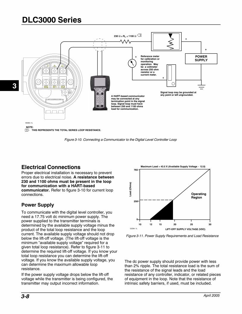
Figure 3-10. Connecting a Communicator to the Digital Level Controller Loop
Reference meterfor calibration ormonitoring operation. Maybe a voltmeteracross 250 ohmresistor or a current meter.
E0363 / IL
1
NOTE:THIS REPRESENTS THE TOTAL SERIES LOOP RESISTANCE.1
Electrical Connections Proper electrical installation is necessary to preventerrors due to electrical noise. A resistance between230 and 1100 ohms must be present in the loopfor communication with a HART-basedcommunicator. Refer to figure 3-10 for current loopconnections.
Power Supply To communicate with the digital level controller, youneed a 17.75 volt dc minimum power supply. Thepower supplied to the transmitter terminals isdetermined by the available supply voltage minus theproduct of the total loop resistance and the loopcurrent. The available supply voltage should not dropbelow the lift-off voltage. (The lift-off voltage is theminimum “available supply voltage” required for agiven total loop resistance). Refer to figure 3-11 todetermine the required lift-off voltage. If you know yourtotal loop resistance you can determine the lift-offvoltage. If you know the available supply voltage, youcan determine the maximum allowable loopresistance.If the power supply voltage drops below the lift-offvoltage while the transmitter is being configured, thetransmitter may output incorrect information.
Maximum Load = 43.5 X (Available Supply Voltage - 12.0)
12 30
LIFT-OFF SUPPLY VOLTAGE (VDC)
Lo
ad (
Oh
ms)
0
10 20 2515
783
250
OperatingRegion
Figure 3-11. Power Supply Requirements and Load Resistance
E0284 / IL
The dc power supply should provide power with lessthan 2% ripple. The total resistance load is the sum ofthe resistance of the signal leads and the loadresistance of any controller, indicator, or related piecesof equipment in the loop. Note that the resistance ofintrinsic safety barriers, if used, must be included.
3

Installation
April 2005 3-9
Field Wiring
NoteFor intrinsically safe applications,refer to the instructions suppliedby the barrier manufacturer.
WARNING
To avoid personal injury or propertydamage caused by fire or explosion,remove power to the instrumentbefore removing the digital levelcontroller cover in an area whichcontains a potentially explosiveatmosphere or has been classified ashazardous.
All power to the digital level controller is supplied overthe signal wiring. Signal wiring need not be shielded,but use twisted pairs for best results. Do not rununshielded signal wiring in conduit or open trays withpower wiring, or near heavy electrical equipment. If thedigital controller is in an explosive atmosphere, do notremove the digital level controller covers when thecircuit is alive, unless in an intrinsically safeinstallation. Avoid contact with leads and terminals. Topower the digital level controller, connect the positivepower lead to the + terminal and the negative powerlead to the - terminal as shown in figure 3-12.
Figure 3-12. Digital Level Controller Terminal Box
4 TO 20 MA LOOPCONNECTIONS
TEST CONNECTIONS
INTERNALGROUNDCONNECTION
1/2-INCH NPT CONDUIT CONNECTION
EXTERNALGROUNDCONNECTION
FRONT VIEW
REAR VIEW
RTDCONNECTIONS
W8041 / IL
CAUTION
Do not apply loop power across the Tand + terminals. This can destroy the 1 Ohm sense resistor in the terminalbox. Do not apply loop power acrossthe Rs and — terminals. This candestroy the 50 Ohm sense resistor inthe electronics module.
3
DLC3000 Series
April 20053-10
When wiring to screw terminals, the use of crimpedlugs is recommended. Tighten the terminal screws toensure that good contact is made. No additional powerwiring is required. All digital level controller coversmust be fully engaged to meet explosion proofrequirements. For ATEX approved units, the terminalbox cover set screw must engage one of the recessesin the terminal box beneath the terminal box cover.
Grounding
WARNING
Personal injury or property damagecan result from fire or explosioncaused by the discharge of staticelectricity when flammable orhazardous gases are present.Connect a 14 AWG (2.1 mm2) groundstrap between the digital levelcontroller and earth ground whenflammable or hazardous gases arepresent. Refer to national and localcodes and standards for groundingrequirements.
The digital level controller will operate with the currentsignal loop either floating or grounded. However, theextra noise in floating systems affects many types ofreadout devices. If the signal appears noisy or erratic,grounding the current signal loop at a single point maysolve the problem. The best place to ground the loopis at the negative terminal of the power supply. As analternative, ground either side of the readout device.Do not ground the current signal loop at more thanone point.
Shielded Wire
Recommended grounding techniques for shielded wireusually call for a single grounding point for the shield.You can either connect the shield at the power supplyor to the grounding terminals, either internal orexternal, at the instrument terminal box shown infigure 3-12.
Power/Current Loop Connections
Use ordinary copper wire of sufficient size to ensurethat the voltage across the digital level controllerterminals does not go below 12.0 volts dc. Connectthe current signal leads as shown in figure 3-10. Aftermaking connections, recheck the polarity andcorrectness of connections, then turn the power on.
RTD Connections
An RTD that senses process temperatures may beconnected to the digital level controller. This permitsthe instrument to automatically make specific gravitycorrections for temperature changes. For best results,locate the RTD as close to the displacer as practical.For optimum EMC performance, use shielded wire nolonger than 3 meters (9.8 feet) to connect the RTD.Connect only one end of the shield. Connect the shieldto either the internal ground connection in theinstrument terminal box or to the RTD thermowell.Wire the RTD to the digital level controller as follows(refer to figure 3-12):
Two-Wire RTD Connections
1. Connect a jumper wire between the RS and R1terminals in the terminal box.
2. Connect the RTD to the R1 and R2 terminals.
Three-Wire RTD Connections
1. Connect the 2 wires which are connected to thesame end of the RTD to the RS and R1 terminals inthe terminal box. Usually these wires are the samecolor.
2. Connect the third wire to terminal R2. (Theresistance measured between this wire and either wireconnected to terminal RS or R1 should read anequivalent resistance for the existing ambienttemperature. Refer to the RTD manufacturer’stemperature to resistance conversion table.) Usuallythis wire is a different color from the wires connectedto the RS and R1 terminals.
Communication Connections
WARNING
Personal injury or property damagecaused by fire or explosion may occurif this connection is attempted in anarea which contains a potentiallyexplosive atmosphere or has beenclassified as hazardous. Confirm thatarea classification and atmosphereconditions permit the safe removal ofthe terminal box cap beforeproceeding.
The 375 Field Communicator interfaces with the TypeDLC3000 digital level controller from any wiringtermination point in the 4–20 mA loop (except acrossthe power supply). If you choose to connect the HART
3
Installation
April 2005 3-11
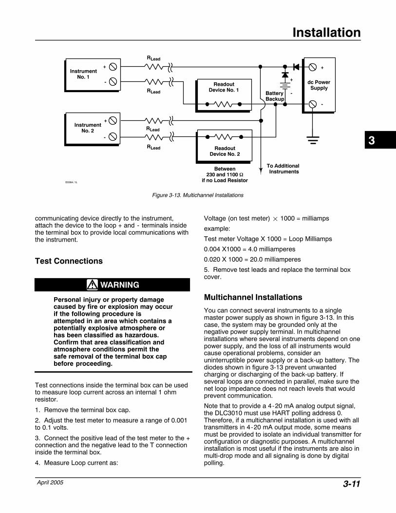
Figure 3-13. Multichannel Installations
RLead
RLead
RLead
+
+
-
-
To Additional InstrumentsBetween
230 and 1100 �if no Load Resistor
InstrumentNo. 2
+
-
InstrumentNo. 1
ReadoutDevice No. 2
ReadoutDevice No. 1
dc PowerSupply
+
-
E0364 / IL
BatteryBackup
+
-
RLead
communicating device directly to the instrument,attach the device to the loop + and - terminals insidethe terminal box to provide local communications withthe instrument.
Test Connections
WARNING
Personal injury or property damagecaused by fire or explosion may occurif the following procedure isattempted in an area which contains apotentially explosive atmosphere orhas been classified as hazardous.Confirm that area classification andatmosphere conditions permit thesafe removal of the terminal box capbefore proceeding.
Test connections inside the terminal box can be usedto measure loop current across an internal 1 ohmresistor.
1. Remove the terminal box cap.
2. Adjust the test meter to measure a range of 0.001to 0.1 volts.
3. Connect the positive lead of the test meter to the +connection and the negative lead to the T connectioninside the terminal box.
4. Measure Loop current as:
Voltage (on test meter) � 1000 = milliamps
example:
Test meter Voltage X 1000 = Loop Milliamps
0.004 X1000 = 4.0 milliamperes
0.020 X 1000 = 20.0 milliamperes
5. Remove test leads and replace the terminal boxcover.
Multichannel Installations
You can connect several instruments to a singlemaster power supply as shown in figure 3-13. In thiscase, the system may be grounded only at thenegative power supply terminal. In multichannelinstallations where several instruments depend on onepower supply, and the loss of all instruments wouldcause operational problems, consider anuninterruptible power supply or a back-up battery. Thediodes shown in figure 3-13 prevent unwantedcharging or discharging of the back-up battery. Ifseveral loops are connected in parallel, make sure thenet loop impedance does not reach levels that wouldprevent communication.
Note that to provide a 4-20 mA analog output signal,the DLC3010 must use HART polling address 0.Therefore, if a multichannel installation is used with alltransmitters in 4-20 mA output mode, some meansmust be provided to isolate an individual transmitter forconfiguration or diagnostic purposes. A multichannelinstallation is most useful if the instruments are also inmulti-drop mode and all signaling is done by digitalpolling.
3
DLC3000 Series
April 20053-12
Alarm Jumper Each digital level controller continuously monitors itsown performance during normal operation. Thisautomatic diagnostic routine is a timed series ofchecks repeated continuously. If diagnostics detect afailure in the electronics, the instrument drives itsoutput to either below 3.70 mA or above 22.5 mA,depending on the position (HI/LO) of the alarm jumper.
An alarm condition occurs when the digital levelcontroller self-diagnostics detect an error that wouldrender the process variable measurement inaccurate,incorrect, or undefined, or a user defined threshold isviolated. At this point the analog output of the unit isdriven to a defined level either above or below thenominal 4-20 mA range, based on the position of thealarm jumper.On encapsulated electronics 14B5483X042 andearlier, if the jumper is missing, the alarm isindeterminate, but usually behaves as a FAIL LOWselection. On encapsulated electronics 14B5483X052and later, the behavior will default to FAIL HIGH whenthe jumper is missing.Alarm Jumper LocationsWithout a meter installed:The alarm jumper is located on the front side of theelectronics module on the electronics side of the digitallevel controller housing, and is labeled FAIL MODE.
With a meter installed:The alarm jumper is located on the LCD faceplate onthe electronics module side of the digital levelcontroller housing, and is labeled FAIL MODE.
Changing Jumper Position
WARNING
Personal injury or property damagecaused by fire or explosion may occurif the following procedure isattempted in an area which contains apotentially explosive atmosphere orhas been classified as hazardous.Confirm that area classification andatmosphere conditions permit thesafe removal of the instrument coverbefore proceeding.
Use the following procedure to change the position ofthe alarm jumper:
1. If the digital level controller is installed, set the loopto manual.
2. Remove the housing cover on the electronics side.Do not remove the cover in explosive atmosphereswhen the circuit is alive.
3. Set the jumper to the desired position.
4. Replace the cover. All covers must be fullyengaged to meet explosion proof requirements. ForATEX approved units, the set screw on the transducerhousing must engage one of the recesses in thecover.
Loop Test (2-2) Loop test can be used to verify the controller output,the integrity of the loop, and the operations of anyrecorders or similar devices installed in the loop. Toinitiate a loop test, perform the following procedure:
1. Connect a reference meter to the controller. To doso, either connect the meter to the test connectionsinside the terminal box (see the Test Connectionsprocedure) or connect the meter in the loop as shownin figure 3-10.
2. From the Online menu, select Diag/Services, andLoop Test, to prepare to perform a loop test.
3. Select OK after you set the control loop to manual.
The Field Communicator displays the loop test menu.
4. Select a discreet milliamp level for the controller tooutput. At the “Choose analog output” prompt, select 4 mA, 20 mA, or Other to manually input a valuebetween 4 and 20 milliamps.
5. Check the reference meter to verify that it readsthe value you commanded the controller to output. Ifthe readings do not match, either the controllerrequires an output trim, or the meter is malfunctioning.
After completing the test procedure, the displayreturns to the loop test screen and allows you tochoose another output value or end the test.
3
Installation
April 2005 3-13
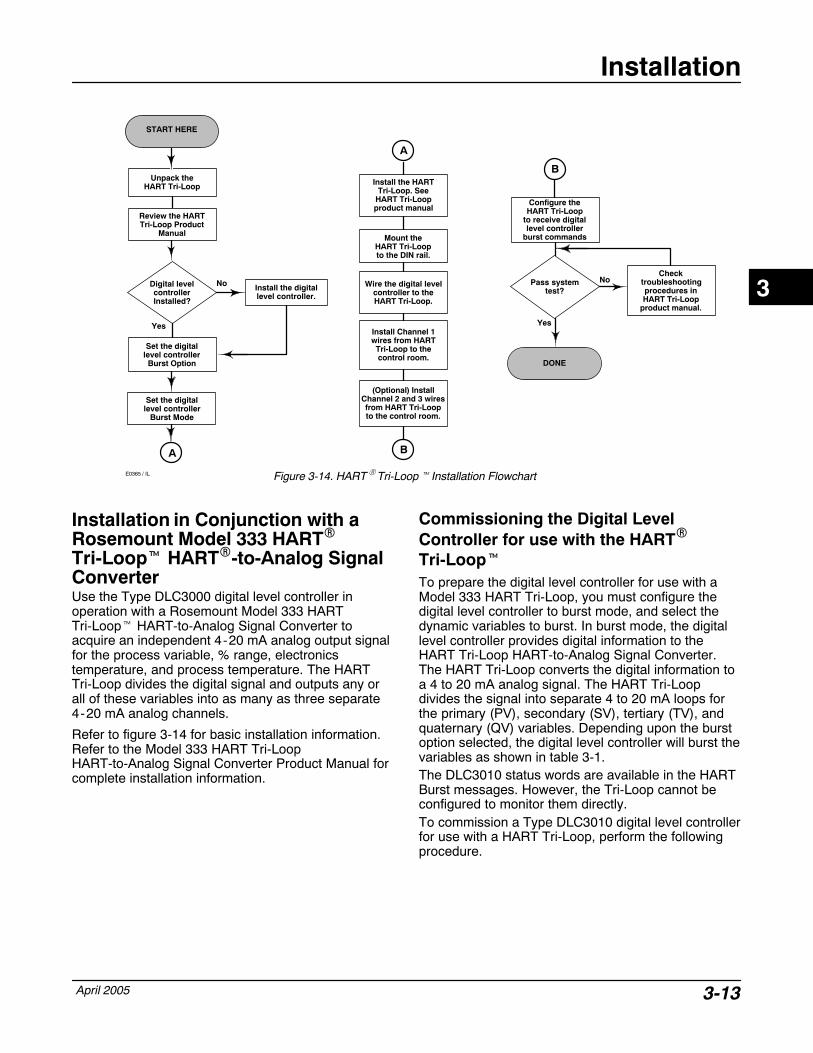
Figure 3-14. HART� Tri-Loop� Installation Flowchart
START HERE
DONE
Digital levelcontrollerInstalled?
Unpack theHART Tri-Loop
Review the HARTTri-Loop Product
Manual
Set the digitallevel controller
Burst Option
Set the digitallevel controller
Burst Mode
A
No
Yes
Install the digitallevel controller.
A
Install the HARTTri-Loop. See
HART Tri-Loopproduct manual
Mount theHART Tri-Loopto the DIN rail.
Wire the digital levelcontroller to theHART Tri-Loop.
Install Channel 1wires from HART
Tri-Loop to thecontrol room.
(Optional) InstallChannel 2 and 3 wiresfrom HART Tri-Loopto the control room.
B
B
Configure theHART Tri-Loop
to receive digitallevel controller
burst commands
Pass systemtest?
Checktroubleshootingprocedures inHART Tri-Loop
product manual.
No
Yes
E0365 / IL
Installation in Conjunction with aRosemount Model 333 HART�
Tri-Loop� HART�-to-Analog SignalConverter Use the Type DLC3000 digital level controller inoperation with a Rosemount Model 333 HARTTri-Loop� HART-to-Analog Signal Converter toacquire an independent 4-20 mA analog output signalfor the process variable, % range, electronicstemperature, and process temperature. The HARTTri-Loop divides the digital signal and outputs any orall of these variables into as many as three separate4-20 mA analog channels.
Refer to figure 3-14 for basic installation information.Refer to the Model 333 HART Tri-LoopHART-to-Analog Signal Converter Product Manual forcomplete installation information.
Commissioning the Digital LevelController for use with the HART�
Tri-Loop�To prepare the digital level controller for use with aModel 333 HART Tri-Loop, you must configure thedigital level controller to burst mode, and select thedynamic variables to burst. In burst mode, the digitallevel controller provides digital information to theHART Tri-Loop HART-to-Analog Signal Converter.The HART Tri-Loop converts the digital information toa 4 to 20 mA analog signal. The HART Tri-Loopdivides the signal into separate 4 to 20 mA loops forthe primary (PV), secondary (SV), tertiary (TV), andquaternary (QV) variables. Depending upon the burstoption selected, the digital level controller will burst thevariables as shown in table 3-1.The DLC3010 status words are available in the HARTBurst messages. However, the Tri-Loop cannot beconfigured to monitor them directly.To commission a Type DLC3010 digital level controllerfor use with a HART Tri-Loop, perform the followingprocedure.
3
DLC3000 Series
April 20053-14
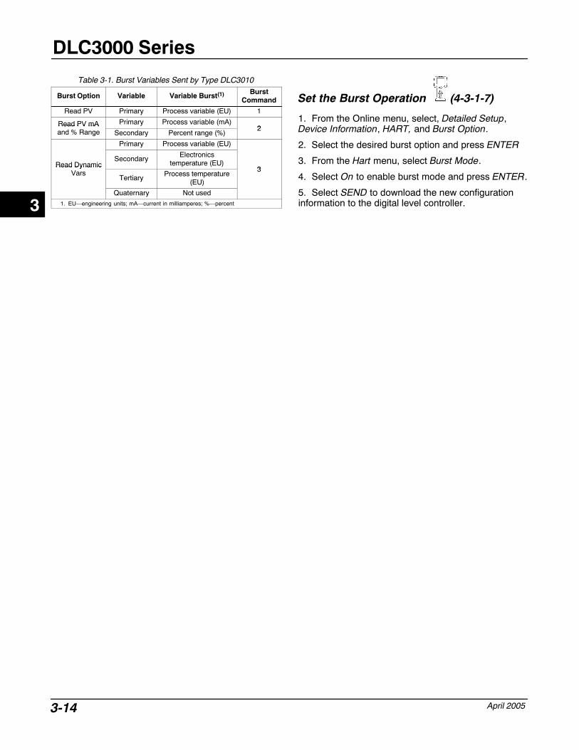
Table 3-1. Burst Variables Sent by Type DLC3010
Burst Option Variable Variable Burst(1) BurstCommand
Read PV Primary Process variable (EU) 1
Read PV mA Primary Process variable (mA)2
Read PV mAand % Range Secondary Percent range (%)
2
Primary Process variable (EU)
Read DynamicSecondary Electronics
temperature (EU)3
Read DynamicVars
Tertiary Process temperature(EU)
3
Quaternary Not used1. EU—engineering units; mA—current in milliamperes; %—percent
Set the Burst Operation (4-3-1-7)
1. From the Online menu, select, Detailed Setup,Device Information, HART, and Burst Option.
2. Select the desired burst option and press ENTER
3. From the Hart menu, select Burst Mode.
4. Select On to enable burst mode and press ENTER.
5. Select SEND to download the new configurationinformation to the digital level controller.3
Setup and Calibration
April 2005 4-1
4-4
Section 4 Setup and Calibration
Initial Setup
Preliminary Considerations 4-5. . . . . . . . . . . . . . . . . . . . . . . . . . . . . . . . . . . . . . . . . . . .
Write Lock 4-5. . . . . . . . . . . . . . . . . . . . . . . . . . . . . . . . . . . . . . . . . . . . . . . . . . . . . . . . . . . . . . .
Level Offset 4-5. . . . . . . . . . . . . . . . . . . . . . . . . . . . . . . . . . . . . . . . . . . . . . . . . . . . . . . . . . . . .
Using the Setup Wizard 4-5. . . . . . . . . . . . . . . . . . . . . . . . . . . . . . . . . . . . . . . . . . . . . . . . .
Coupling 4-7. . . . . . . . . . . . . . . . . . . . . . . . . . . . . . . . . . . . . . . . . . . . . . . . . . . . . . . . . . . . . . . .
Calibration
Introduction: Calibration of Smart Instruments 4-8. . . . . . . . . . . . . . . . . . . . . . .
Quick Calibration 4-8. . . . . . . . . . . . . . . . . . . . . . . . . . . . . . . . . . . . . . . . . . . . . . . . . . . . . . .
PV Sensor Calibration 4-8. . . . . . . . . . . . . . . . . . . . . . . . . . . . . . . . . . . . . . . . . . . . . . . . . .
Procedures that Affect the Zero of the PV Calculation 4-9. . . . . . . . . . . . . . . . . . . Mark Dry Coupling 4-9. . . . . . . . . . . . . . . . . . . . . . . . . . . . . . . . . . . . . . . . . . . . . . . . . . . . . Trim PV Zero 4-9. . . . . . . . . . . . . . . . . . . . . . . . . . . . . . . . . . . . . . . . . . . . . . . . . . . . . . . . . .
Procedures that Affect the Gain of the PV Calculation 4-10. . . . . . . . . . . . . . . . . . . Two-Point Sensor Calibration 4-10. . . . . . . . . . . . . . . . . . . . . . . . . . . . . . . . . . . . . . . . . . . . Single-Point Sensor Calibration 4-11. . . . . . . . . . . . . . . . . . . . . . . . . . . . . . . . . . . . . . . . . . Wet/Dry Calibration 4-11. . . . . . . . . . . . . . . . . . . . . . . . . . . . . . . . . . . . . . . . . . . . . . . . . . . . Weight-Based Calibration 4-12. . . . . . . . . . . . . . . . . . . . . . . . . . . . . . . . . . . . . . . . . . . . . . . Theoretical Calibration 4-12. . . . . . . . . . . . . . . . . . . . . . . . . . . . . . . . . . . . . . . . . . . . . . . . . .
Ranging Operations 4-13. . . . . . . . . . . . . . . . . . . . . . . . . . . . . . . . . . . . . . . . . . . . . . . . . . . .
Temperature Calibration 4-13. . . . . . . . . . . . . . . . . . . . . . . . . . . . . . . . . . . . . . . . . . . . . . . .
Manual Entry of Process Temperature 4-14. . . . . . . . . . . . . . . . . . . . . . . . . . . . . . . . . . . .
Output DAC Calibration:Scaled D/A Trim 4-14. . . . . . . . . . . . . . . . . . . . . . . . . . . . .
Calibration Examples 4-14. . . . . . . . . . . . . . . . . . . . . . . . . . . . . . . . . . . . . . . . . . . . . . . . . . .
Level Application 4-14. . . . . . . . . . . . . . . . . . . . . . . . . . . . . . . . . . . . . . . . . . . . . . . . . . . . . . . .
Interface Application
4
DLC3000 Series
April 20054-2
with standard displacer and torque tube 4-15. . . . . . . . . . . . . . . . . . . . . . . . . . . . . . . . . . . . . with an overweight displacer 4-15. . . . . . . . . . . . . . . . . . . . . . . . . . . . . . . . . . . . . . . . . . . . . . .
Density Applications 4-16. . . . . . . . . . . . . . . . . . . . . . . . . . . . . . . . . . . . . . . . . . . . . . . . . . . . .
Calibration at Process Conditions (Hot Cut-Over) when input cannot be varied 4-17. . . . . . . . . . . . . . . . . . . . . . . . . . . . . . . . . . . . . . . . . . . . . . . . . . . . . . .
Entering Theoretical Torque Tube Rates 4-18. . . . . . . . . . . . . . . . . . . . . . . . . . . . . . . . . .
Accuracy Considerations 4-18. . . . . . . . . . . . . . . . . . . . . . . . . . . . . . . . . . . . . . . . . . . . . .
Effect of Proportional Band 4-18. . . . . . . . . . . . . . . . . . . . . . . . . . . . . . . . . . . . . . . . . . . . . . .
Density Variations in Interface Applications 4-19. . . . . . . . . . . . . . . . . . . . . . . . . . . . . . .
High Process Temperatures 4-19. . . . . . . . . . . . . . . . . . . . . . . . . . . . . . . . . . . . . . . . . . . . . .
Temperature Compensation 4-19. . . . . . . . . . . . . . . . . . . . . . . . . . . . . . . . . . . . . . . . . . . . . .
Detailed Setup
Menu and Quick Key Sequence Tables Front Cover. . . . . . . . . . . . . . . . . . . . . . . . . . . . . . .
Setting Protection 4-20. . . . . . . . . . . . . . . . . . . . . . . . . . . . . . . . . . . . . . . . . . . . . . . . . . . . . . .
Setting Up the Sensor 4-20. . . . . . . . . . . . . . . . . . . . . . . . . . . . . . . . . . . . . . . . . . . . . . . . . .
Entering Displacer Data 4-20. . . . . . . . . . . . . . . . . . . . . . . . . . . . . . . . . . . . . . . . . . . . . . . . . .
Entering Torque Tube Data 4-20. . . . . . . . . . . . . . . . . . . . . . . . . . . . . . . . . . . . . . . . . . . . . .
Specifying Instrument Mounting 4-20. . . . . . . . . . . . . . . . . . . . . . . . . . . . . . . . . . . . . . . . . .
Process Temperature Indications 4-20. . . . . . . . . . . . . . . . . . . . . . . . . . . . . . . . . . . . . . . . . Entering RTD Data 4-20. . . . . . . . . . . . . . . . . . . . . . . . . . . . . . . . . . . . . . . . . . . . . . . . . . . . . . . Setting Temperature Units 4-21. . . . . . . . . . . . . . . . . . . . . . . . . . . . . . . . . . . . . . . . . . . . . . . .
Setting Up the Instrument for the Application 4-21. . . . . . . . . . . . . . . . . . . . . . . .
Selecting the Process Variable 4-21. . . . . . . . . . . . . . . . . . . . . . . . . . . . . . . . . . . . . . . . . . .
Setting PV Engineering Units 4-21. . . . . . . . . . . . . . . . . . . . . . . . . . . . . . . . . . . . . . . . . . . . . Process Variable Units 4-21. . . . . . . . . . . . . . . . . . . . . . . . . . . . . . . . . . . . . . . . . . . . . . . . . . . . Displacer Units 4-21. . . . . . . . . . . . . . . . . . . . . . . . . . . . . . . . . . . . . . . . . . . . . . . . . . . . . . . . . . Torque Tube Rate Units 4-21. . . . . . . . . . . . . . . . . . . . . . . . . . . . . . . . . . . . . . . . . . . . . . . . . .
Setting PV Range 4-21. . . . . . . . . . . . . . . . . . . . . . . . . . . . . . . . . . . . . . . . . . . . . . . . . . . . . . . . Instrument Action 4-21. . . . . . . . . . . . . . . . . . . . . . . . . . . . . . . . . . . . . . . . . . . . . . . . . . . . . . . . Reverse Action 4-21. . . . . . . . . . . . . . . . . . . . . . . . . . . . . . . . . . . . . . . . . . . . . . . . . . . . . . . . . . Entering the Upper and Lower Range Values 4-22. . . . . . . . . . . . . . . . . . . . . . . . . . . . . . . . Setting Zero and Span 4-22. . . . . . . . . . . . . . . . . . . . . . . . . . . . . . . . . . . . . . . . . . . . . . . . . . . .
Setting Level Offset 4-23. . . . . . . . . . . . . . . . . . . . . . . . . . . . . . . . . . . . . . . . . . . . . . . . . . . . . . . .
Setting PV Damping 4-23. . . . . . . . . . . . . . . . . . . . . . . . . . . . . . . . . . . . . . . . . . . . . . . . . . . . .
Setting Input Filter 4-24. . . . . . . . . . . . . . . . . . . . . . . . . . . . . . . . . . . . . . . . . . . . . . . . . . . . . . .
Setting the Specific Gravity 4-24. . . . . . . . . . . . . . . . . . . . . . . . . . . . . . . . . . . . . . . . . . . . . . .
4
Setup and Calibration
April 2005 4-3
Setting Up the LCD Meter 4-25. . . . . . . . . . . . . . . . . . . . . . . . . . . . . . . . . . . . . . . . . . . . . .
Testing the Meter 4-25. . . . . . . . . . . . . . . . . . . . . . . . . . . . . . . . . . . . . . . . . . . . . . . . . . . . . . . .
Setting Alarms 4-26. . . . . . . . . . . . . . . . . . . . . . . . . . . . . . . . . . . . . . . . . . . . . . . . . . . . . . . . . .
Setting Process Variable Alarm Limits 4-26. . . . . . . . . . . . . . . . . . . . . . . . . . . . . . . . . . . . Process Variable High AlarmProcess Variable High High AlarmProcess Variable Low AlarmProcess Variable Low Low AlarmProcess Variable Alarm Deadband
Setting Temperature Alarm Limits 4-26. . . . . . . . . . . . . . . . . . . . . . . . . . . . . . . . . . . . . . . . Temperature High AlarmTemperature Low AlarmElectronics Temperature High AlarmElectronics Temperature Low AlarmTemperature Alarm Deadband
Enabling Process Variable Alarms 4-27. . . . . . . . . . . . . . . . . . . . . . . . . . . . . . . . . . . . . . . . PV High AlarmPV High High AlarmPV Low AlarmPV Low Low Alarm
Enabling Temperature Alarms 4-27. . . . . . . . . . . . . . . . . . . . . . . . . . . . . . . . . . . . . . . . PV Temperature High AlarmPV Temperature Low AlarmElectronics Temperature High AlarmElectronics Temperature Low Alarm
Entering HART� Information 4-28. . . . . . . . . . . . . . . . . . . . . . . . . . . . . . . . . . . . . . . . . . .
HART� Tag
Polling AddressMessage
Descriptor
Date
Multidrop Communication 4-29. . . . . . . . . . . . . . . . . . . . . . . . . . . . . . . . . . . . . . . . . . . . . .
Temperature Compensation 4-29. . . . . . . . . . . . . . . . . . . . . . . . . . . . . . . . . . . . . . . . . . .
4
DLC3000 Series
April 20054-4
Initial Setup If a Type DLC3010 digital level controller ships fromthe factory mounted on a 249 Series sensor, initialsetup and calibration is not necessary. The factoryenters the sensor data, couples the instrument to thesensor, and calibrates the instrument and sensorcombination.
NoteIf you received the digital levelcontroller mounted on the sensor withthe displacer blocked, or if thedisplacer is not connected, theinstrument will be coupled to thesensor and the lever assemblyunlocked. To place the unit in service,if the displacer is blocked, remove therod and block at each end of thedisplacer and check the instrumentcalibration. (If the “factory cal” optionwas ordered, the instrument will beprecompensated to the processconditions provided on the requisition,and will not appear to be calibrated ifchecked against room temperature 0and 100% water level inputs).
If the displacer is not connected, hangthe displacer on the torque tube, andre-zero the instrument by performingthe Mark Dry Coupling procedure.
If you received the digital levelcontroller mounted on the sensor andthe displacer is not blocked (such asin skid mounted systems), theinstrument will not be coupled, to thesensor, and the lever assembly will belocked. To place the unit in service,unlock the lever assembly and couplethe instrument to the sensor. Thenperform the Mark Dry Couplingprocedure.
To review the configuration data entered by thefactory, connect the instrument to a 24 volt dc powersupply as shown in figure 3-10. Connect the 375 Field
Communicator to the instrument and turn it on. Fromthe Online menu select Review then select DeviceParams (Device Parameters). If your application datahas changed since the instrument wasfactory-configured, refer to the Detailed Setup sectionfor instructions on modifying configuration data.
For instruments not mounted on a level sensor orwhen replacing an instrument, initial setup consists ofentering sensor information so that the digital levelcontroller matches the sensor. Once the sensorinformation is entered, the next step is coupling thesensor to the digital level controller. When the digitallevel controller and sensor are coupled, thecombination may be calibrated.
Sensor information includes displacer and torque tubeinformation, such as:
� Length units (meters, inches, or centimeters)
� Volume units (cubic inches, cubic millimeters, ormilliliters)
� Weight units (kilograms, pounds, or ounce)
� Displacer Length
� Displacer Volume
� Displacer Weight
� Displacer Driver Rod Length (moment arm) (seetable 4-1)
� Torque Tube Material
� Instrument mounting (right or left of displacer)
� Measurement Application (level, interface, ordensity)
NoteA sensor with a K-Monel torque tubemay have NiCu on the nameplate asthe torque tube material.
4
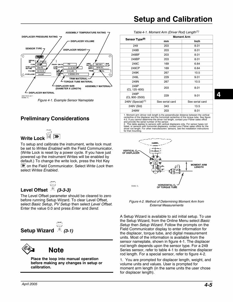
Setup and Calibration
April 2005 4-5
Figure 4-1. Example Sensor Nameplate
DISPLACER PRESSURE RATING
1500 PSI
103 CU-IN
316 SST
249B
76543210
PSI
2 x 32 INCHES
4 3/4 LBS
K MONEL/STD
285/100 F
WCB STL
MONEL
DISPLACER MATERIAL
DISPLACER VOLUME
DISPLACER SIZE(DIAMETER X LENGTH)
TORQUE TUBE MATERIAL
SENSOR TYPE DISPLACER WEIGHT
ASSEMBLY TEMPERATURE RATING
ASSEMBLY MATERIAL
TRIM MATERIAL
23A1725-E sht 1E0366 / IL
Preliminary Considerations
Write LockTo setup and calibrate the instrument, write lock mustbe set to Writes Enabled with the Field Communicator.(Write Lock is reset by a power cycle. If you have justpowered up the instrument Writes will be enabled bydefault.) To change the write lock, press the Hot Key
on the Field Communicator. Select Write Lock thenselect Writes Enabled.
Level Offset (3-3-3)The Level Offset parameter should be cleared to zerobefore running Setup Wizard. To clear Level Offset,select Basic Setup, PV Setup then select Level Offset.Enter the value 0.0 and press Enter and Send.
Setup Wizard (3-1)
NotePlace the loop into manual operationbefore making any changes in setup orcalibration.
Table 4-1. Moment Arm (Driver Rod) Length(1)
Sensor Type(2)Moment Arm
Sensor Type(2)mm Inch
249 203 8.01
249B 203 8.01
249BF 203 8.01
249BP 203 8.01
249C 169 6.64
249CP 169 6.64
249K 267 10.5
249L 229 9.01
249N 267 10.5
249P(CL 125-600)
203 8.01
249P(CL 900-2500)
229 9.01
249V (Special)(1) See serial card See serial card
249V (Std) 343 13.5
249W 203 8.011. Moment arm (driver rod) length is the perpendicular distance between the verticalcenterline of the displacer and the horizontal centerline of the torque tube. See figure4-2. If you cannot determine the driver rod length, contact your Fisher sales officeand provide the serial number of the sensor.2. This table applies to sensors with vertical displacers only. For sensor types notlisted, or sensors with horizontal displacers, contact your Fisher sales office for thedriver rod length. For other manufacturers’ sensors, see the installation instructionsfor that mounting.
Figure 4-2. Method of Determining Moment Arm fromExternal Measurements
E0283 / IL HORIZONTAL CLOF TORQUE TUBE
VERTICAL CL OF DISPLACER
MOMENT ARMLENGTH
A Setup Wizard is available to aid initial setup. To usethe Setup Wizard, from the Online Menu select BasicSetup then Setup Wizard. Follow the prompts on theField Communicator display to enter information forthe displacer, torque tube, and digital measurementunits. Most of the information is available from thesensor nameplate, shown in figure 4-1. The displacerrod length depends upon the sensor type. For a 249Series sensor, refer to table 4-1 to determine displacerrod length. For a special sensor, refer to figure 4-2.
1. You are prompted for displacer length, weight, andvolume units and values. User is prompted formoment arm length (in the same units the user chosefor displacer length).
4
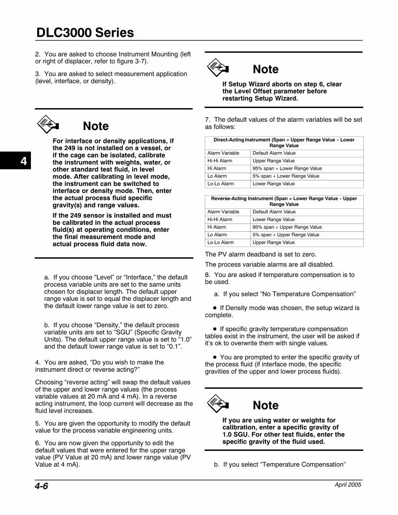
DLC3000 Series
April 20054-6
2. You are asked to choose Instrument Mounting (leftor right of displacer, refer to figure 3-7).
3. You are asked to select measurement application(level, interface, or density).
NoteFor interface or density applications, ifthe 249 is not installed on a vessel, orif the cage can be isolated, calibratethe instrument with weights, water, orother standard test fluid, in levelmode. After calibrating in level mode,the instrument can be switched tointerface or density mode. Then, enterthe actual process fluid specificgravity(s) and range values.
If the 249 sensor is installed and mustbe calibrated in the actual processfluid(s) at operating conditions, enterthe final measurement mode andactual process fluid data now.
a. If you choose “Level” or “Interface,” the defaultprocess variable units are set to the same unitschosen for displacer length. The default upperrange value is set to equal the displacer length andthe default lower range value is set to zero.
b. If you choose “Density,” the default processvariable units are set to “SGU” (Specific GravityUnits). The default upper range value is set to “1.0”and the default lower range value is set to “0.1”.
4. You are asked, “Do you wish to make theinstrument direct or reverse acting?”
Choosing “reverse acting” will swap the default valuesof the upper and lower range values (the processvariable values at 20 mA and 4 mA). In a reverseacting instrument, the loop current will decrease as thefluid level increases.
5. You are given the opportunity to modify the defaultvalue for the process variable engineering units.
6. You are now given the opportunity to edit thedefault values that were entered for the upper rangevalue (PV Value at 20 mA) and lower range value (PVValue at 4 mA).
NoteIf Setup Wizard aborts on step 6, clearthe Level Offset parameter beforerestarting Setup Wizard.
7. The default values of the alarm variables will be setas follows:
Direct-Acting Instrument (Span = Upper Range Value - LowerRange Value
Alarm Variable Default Alarm Value
Hi-Hi Alarm Upper Range Value
Hi Alarm 95% span + Lower Range Value
Lo Alarm 5% span + Lower Range Value
Lo-Lo Alarm Lower Range Value
Reverse-Acting Instrument (Span = Lower Range Value - UpperRange Value
Alarm Variable Default Alarm Value
Hi-Hi Alarm Lower Range Value
Hi Alarm 95% span + Upper Range Value
Lo Alarm 5% span + Upper Range Value
Lo-Lo Alarm Upper Range Value
The PV alarm deadband is set to zero.
The process variable alarms are all disabled.
8. You are asked if temperature compensation is tobe used.
a. If you select “No Temperature Compensation”
� If Density mode was chosen, the setup wizard iscomplete.
� If specific gravity temperature compensationtables exist in the instrument, the user will be asked ifit’s ok to overwrite them with single values.
� You are prompted to enter the specific gravity ofthe process fluid (if interface mode, the specificgravities of the upper and lower process fluids).
NoteIf you are using water or weights forcalibration, enter a specific gravity of1.0 SGU. For other test fluids, enter thespecific gravity of the fluid used.
b. If you select “Temperature Compensation”
4
Setup and Calibration
April 2005 4-7
Two specific gravity tables are available in theinstrument to provide specific gravity correction fortemperature (see tables 4-3 and 4-4). For interfacelevel applications, both tables are used. For levelmeasurement applications, only the lower specificgravity table is used. Neither table is used for densityapplications. Both tables may be edited during detailedsetup. The Setup Wizard asks if the tables should beused. If not, then you must supply a specific gravityvalue (or values for interface applications).
� If Density mode was NOT chosen, the user willbe presented with the current specific gravitytemperature compensation table (or lower fluid specificgravity temperature compensation table if interfaceapplication) for edit. The user can accept the currenttable(s), modify an individual entry, or enter a newtable manually. For an interface application, the usercan switch between the upper and lower fluid tables.
� You are prompted to choose a torque tubematerial. The instrument loads the default torque tubetemperature compensation table for the materialchosen. If you choose “Unknown” for the material, theK-Monel temperature compensation table is loaded. Ifyou choose “Special” the current table in theinstrument will be left unchanged, but the label for thematerial is changed to “Special”. This feature allows aspecial user table to be retained without overwriting,but does not allow it to be copied to a storedconfiguration.
� You are presented with the torque-tubetemperature compensation table for edit. You canaccept the table, edit an individual table entry, load atemperature compensation table for a different torquetube material, or enter a new table manually. If atemperature compensation table for a differentmaterial is chosen, the torque tube material will beupdated to reflect the new material chosen. If a newtable is entered manually, or an individual entry ismodified, then the torque tube material will bechanged to “Special.”
NoteIn firmware version 07 and 08, the datatables for torque-tube correction aresimply stored without implementation.The user may use the information topre-compensate the measuredtorque-tube rate manually.
Coupling After entering the sensor information, the SetupWizard prompts you to couple the digital levelcontroller to the sensor. If not already coupled,perform the following procedure to couple the digitallevel controller to the sensor.1. Slide the access handle to the locked position toexpose the access hole. Press on the back of thehandle as shown in figure 3-5 then slide the handletoward the front of the unit. Be sure the locking handledrops into the detent.2. Set the displacer to the lowest possible processcondition, (i.e. lowest water level or minimum specificgravity) or replace the displacer by the heaviestcalibration weight.
NoteInterface or density applications withdisplacer/torque tube sized for a smalltotal change in specific gravity aredesigned to be operated with thedisplacer always submerged. In theseapplications, the torque rod issometimes resting on a stop while thedisplacer is dry. The torque tube doesnot begin to move until a considerableamount of liquid has covered thedisplacer. In this case, couple with thedisplacer submerged in the fluid withthe lowest density and the highestprocess temperature condition, or withan equivalent condition simulated withthe calculated weights.
If the sizing of the sensor results in aproportional band greater than 100%(total expected rotational span greaterthan 4.4 degrees), couple thetransmitter to the pilot shaft while atthe 50% process condition to makemaximum use of available transmittertravel (�6�). The Mark Dry Couplingprocedure is still performed at the zerobuoyancy (or zero differentialbuoyancy) condition.
3. Insert a 10 mm deep well socket through theaccess hole and onto the torque tube shaft clamp nut.Tighten the clamp nut to a maximum torque of 2.1 N�m(18 lbf�in).
4. Slide the access handle to the unlocked position.(Press on the back of the handle as shown in figure3-5 then slide the handle toward the rear of the unit.)Be sure the locking handle drops into the detent.
4
DLC3000 Series
April 20054-8
Calibration
Introduction: Calibration of SmartInstruments
Analog instruments generally have only one interfacethat can be calibrated by the user. A zero and spanoutput calibration is normally performed at thecorresponding two input conditions. Zero/Spancalibration is very simple to use, but provides littleversatility. If the 0% and 100% input conditions are notavailable to the user, a calibration can sometimes beaccomplished, but the gain and offset adjustments willlikely interact, requiring considerable iteration toachieve accuracy. In contrast, intelligent instrumentshave many interfaces that can be calibrated or scaledby the user, with consequent increased versatility.
Refer to table 4-2 for a list of relationships in theDLC3000 that can be calibrated or configured by theuser. Note that not all relationships are listed here.
These parameters are factory-set to the most commonvalues for the 249 Series products. Therefore, for thebulk of units sold in simple level applications, it ispossible to accept the defaults and proceed to asimple zero-and-span operation. If any of theadvanced features of the instrument are to be used,accurate sensor and test fluid information shouldgenerally be entered before beginning the calibration.
Quick Calibration
The following procedure may be used to calibrate theinstrument as an analog transmitter replacement. Theoutput 4 and 20 mA conditions will be related to agiven pair of mechanical input conditions only, the PVin engineering units will not be calibrated. Thisapproach will give satisfactory results for many of thesimple level measurement applications encountered.
NoteThis procedure assumes that you areusing the instrument in LevelMeasurement Mode, even if theprocess is interface or density.
The SG value used for Level is theactual fluid SG, the SG value used forInterface is the difference between theSGs upper and lower fluid, and, the SGvalue entered for Density would be thedifference between the minimum andmaximum density range of theapplication.
1. Connect a 24 VDC supply and 250 Ohm minimumseries resistance, and a 375 Field Communicator.2. Enter the mounting sense (4-1-1-1-2), then SEND.3. Set Level Offset to zero (3-3-3); then SEND.4. Set PV is (3-3-6) to LEVEL, then SEND.5. Set Specific Gravity to the difference between SGsof the upper and lower fluids (3-3-5).6. Set up the lowest process condition (or hangweight equal to the displacer weight - minimumbuoyancy).7. Couple to the 249 Series transmitter and close theaccess door (this unlocks the lever assembly).8. Mark Dry-Coupling point (this marks zerobuoyancy). (3-2-1).9. Set Zero (3-3-2-5-1).10. Set up the highest process condition (or hangweight equal to the displacer weight - maximumbuoyancy).11. Set Span (3-3-2-5-2).12. Set Meter Type to % Range Only (4-2-2-2-3).
PV Sensor CalibrationIf the advance capabilities of the transmitter are to beused, it is necessary to calibrate the PV sensorinstead of using the “zero and span” approach. Thefollowing is a description of the functionality of thevarious HART command procedures for calibrating thesensor. Subsequently, we will relate which proceduresto use in a given scenario, and in which order to applythem.
4

Setup and Calibration
April 2005 4-9
Procedures that Affect the Zero of the PVCalculation
Mark Dry Coupling (3-2-1)
This procedure captures the current pilot shaft rotationvalue and associates it with the zero buoyancy or “drydisplacer” condition. (If the pilot shaft is not alreadyphysically coupled to the transmitter, perform themechanical procedure under Coupling first). The MarkDry Coupling procedure prompts you to hang thedisplacer, unlock the lever arm, and verify that thedisplacer is completely dry.
From the Online menu, select Basic Setup, SensorCalibrate, and Mark Dry Coupling. Follow the promptson the Field Communicator to mark the dry couplingpoint.
NoteIf the handle on the coupling accessdoor is in the position towards thefront of the transmitter, the couplingaccess hole is open and the lever is“locked” (pinned in the neutral travelposition). In this condition, the true“at-rest” position of the linkage maynot be captured correctly. Moving thehandle to the rear of the transmittercloses the coupling-access hole andunlocks the lever.
The captured number can be read back as the“Reference Coupling Point”. It functions as thepre-calculation zero for the process measurementalgorithm. This procedure can be run either before orafter most of the gain calibrations, (with the exceptionof the “single-point” calibration, for which couplingpoint must have been marked first). However, theprocedure returns a valid result at only one inputcondition - zero buoyancy.
Table 4-2. Relationships in the DLC3000 that can be UserCalibrated or Configured
Torque TubeRate
The scale factor between the internal digitalrepresentation of the measured pilot shaft rotationand the physical torque input to the sensor.
Reference (dry)Coupling Point
The angle of pilot shaft rotation associated withthe zero buoyancy condition. (The zero referencefor the input of the PV calculation).
Driver RodLength
The scale factor (moment arm) between a forceinput to the sensor driver rod and the torquedeveloped as input to the torque tube.
DisplacerVolume
The scale factor relating the density of theprocess fluid to the maximum force that can beproduced as an input to the driver rod of thesensor.
SG
The density of the process fluid normalized to thedensity of water at reference conditions. Thescale factor that transforms displacer volume andmeasured buoyancy into a level signal normalizedto displacer length.
Displacer Length The scale factor to convert normalized level tolevel on the displacer in engineering units.
Level OffsetThe zero reference for the output of the PVcalculation, referred to the location of the bottomof the displacer at zero buoyancy condition.
URV (UpperRange Value)
The value of computed process variable at whicha 20 mA output (100% Range) is desired.
LRV (LowerRange Value)
The value of computed process variable at whicha 4 mA output (0% Range) is desired.
DAC Trim The gain and offset of the D/A converter whichexecutes the digital commands to generate output
Elec TempOffset
Bias to improve the accuracy of the ambienttemperature measurement used to providetemperature compensation for themechanical-to-electronic transducer.
Proc TempOffset
Bias to improve the accuracy of the (RTD)temperature measurement used to providecompensation for process-temperature-relateddensity changes.
Trim PV Zero (3-2-5)
This procedure computes and adds an offset to thecomputed process variable, so that the computedvalue matches the user’s external observation of theprocess measurement. For example (see figure 4-4), ifthe bottom of the displacer is 4 feet above the bottomof the vessel, and the user’s observation is measuredfrom the bottom of the vessel, a Level Offset value of4 feet would be computed. The liquid level indicatedby the PV would then be referenced to the bottom ofthe vessel. If the Level Offset is 0.0, the reference forthe PV measurement is understood to be the locationof the bottom of the displacer at the dry condition.Other useful references would include the center ofthe displacer, the system set-point, or even sea level.(It may not be possible to use sea level as a referencein many cases, as there is currently a 100 ft.magnitude limit on the Level Offset parameter).
4
DLC3000 Series
April 20054-10
The Level Offset parameter can also be editedmanually under Basic Setup, PV Setup, Level Offset(3-3-3).
If the computed process variable is biased due to theinability to mark the reference coupling point correctly,(which can happen when the sensor hardware isoversized to provide additional gain for someinterface-level applications), the Level Offset(computed by Trim PV Zero or entered manually) canbe used to trim out that bias. However, thereasonableness limits (USL, LSL) on the range valuesare also shifted by the Level Offset. If the magnitudeof the Level Offset value exceeds 20% of the displacerlength, at least one of the desired range values will nolonger be inside the legal range. Checking rangevalues against the USL and LSL is only done whenwriting the range values, so in systems that use theDLC3000 DD, it is possible to temporarily remove theoffset, adjust the range values, and replace the offsetafterwards.
NoteOn systems that cannot access theLevel Offset, and that write the rangevalues automatically duringinitialization, (such as DeltaV�), it isnot advisable to use Trim PV Zero tocompensate for an invalid ReferenceCoupling Point. If a communicationdrop-out occurs, DeltaV will attempt towrite unit and range data to the DLC.DeltaV will continuously repeatinitialization attempts when a rangevalue is rejected. The other parametersthat are successfully written duringeach iteration will rapidly use up thewrite-cycle life of the NVM in theDLC3000’s microprocessor.
The Level Offset is effectively a post-calculation zero.Therefore, the Trim PV Zero procedure should beperformed after the gain calibration, but it may be runat any valid process condition. The range valuesshould be set after running Trim PV Zero if it is beingused to shift the zero reference away from the bottomof the displacer. The range values must be set beforerunning Trim PV Zero if it is being used to compensatefor an invalid Reference Coupling Point.
NoteThe Trim PV Zero command and LevelOffset parameter are not available indensity measurement mode atfirmware revision 8. If displacer sizingfor a density application results in anoverweight displacer, it will benecessary to set the system up inLevel or Interface measurement modeto calibrate effectively. The output ofthe instrument will only make sense in“% Range” units in such a case, sincedensity units are not available in Levelor Interface Mode.
From the Online menu, select Basic Setup, SensorCalibrate, and Trim PV Zero.
Follow the prompts on the Field Communicator.
1. Adjust the process condition or simulation to anyvalid and observable value.
2. Enter the external observation of the measurementin the current PV units. The Level Offset is computedand stored.
3. Recheck the upper and lower range values againstthe USL and LSL. If the offset is being added to shiftthe physical zero reference, shift the range values bythe same amount. If you are trimming out a ReferenceCoupling Point calibration error, note whether one ofthe range values has become illegal. If so, it will benecessary to temporarily remove the Level Offsetbefore running the Setup Wizard or changing therange values. If the range values will be writtenautomatically by any system, do not use the Trim PVZero command for trimming out a Reference CouplingPoint error. Instead, use Level measurement mode,enter the delta SG between fluids as the system SG,and Mark Dry Coupling point at the lowest processcondition. The Reference Coupling Point will thenrepresent the zero differential buoyancy condition, andthe algorithm will compute the interface level correctly.
Procedures that Affect the Gain of the PVCalculation
Two-Point Sensor Calibration (3-2-2)
This procedure is usually the most accurate methodfor calibrating the sensor. It uses independentobservations of two valid process conditions, togetherwith the hardware dimensional data and SGinformation, to compute the effective torque rate of the
4
Setup and Calibration
April 2005 4-11
sensor. The two data points can be separated by anyspan between a few percent to 100%, as long as theyremain on the displacer. Within this range, thecalibration accuracy will generally increase as thedata-point separation gets larger. Accuracy is alsoimproved by running the procedure at processtemperature, as the temperature effect on torque ratewill be captured. (It is possible to use theoretical datato pre-compensate the measured torque rate for atarget process condition when the calibration must berun at ambient conditions.)
An external method of measuring the processcondition is required. This procedure may be runbefore or after marking the coupling point. It adjuststhe calculation gain only, so the change in PV outputwill track the change in input correctly after thisprocedure. However, there may be a constant bias inthe PV until the Mark Dry Coupling procedure hasbeen run.
From the Online menu, select Basic Setup, SensorCalibrate, and Two Point.
Follow the prompts on the Field Communicator tocalibrate the sensor.
1. Put the control loop in manual control.
2. Adjust the process condition to a value near the topor bottom of the valid range.
3. Enter this externally measured process condition inthe current PV units.
4. Adjust the process condition to a value near thebottom or top of the valid range, but at a position thatis toward the opposite end of the range relative to thecondition used in step
5. Enter this second externally measured processcondition in the current PV units.
The sensor torque rate is now calibrated. Be sure toverify that there is no bias in the PV calculation andthat the upper and lower range values are correctbefore returning the loop to automatic control.
Single-Point Sensor Calibration (3-2-4)
This procedure uses the previously stored ReferenceCoupling Point, together with a single independentobservation of the current process condition, tocompute the sensor torque rate. The Single-Pointsensor calibration procedure is useful when the drycondition can only be established during a plant shutdown, and/or the process condition is difficult tochange during operation. (e.g., a top or side-mountedcageless sensor on a large vessel.)
An accurate means of externally measuring theprocess condition is required. A valid Reference
Coupling Point, (representing either zero buoyancy orzero differential buoyancy), must have been previouslystored. Actions that improve the accuracy of thiscalibration method include:
a. entering the correct displacer information,
b. entering the actual SG of the process fluid, and
c. running the Mark Dry Coupling procedure withthe torque tube at the same temperature it willreach under process conditions, (or an accuratesimulation of that rotation).
From the Online menu, select Basic Setup, SensorCalibrate, and Single Point.
Follow the prompts on the Field Communicator tocalibrate the instrument and sensor.
1. Allow the process condition to settle to a stable,non-zero value.
2. Enter the externally measured process condition inthe current PV units.
The sensor torque rate is calibrated. Be sure to verifythat the upper and lower range values are correctbefore returning the loop to automatic control. Thereshould be no bias in the PV calculation if thepreviously stored Reference Coupling Point wasaccurate.
If the PV does not match the observed process afterusing this procedure, there is likely to be both a gainerror and a bias error present. This is due to a changein the actual zero buoyancy rotation compared to thestored value. If it is possible, repeat the Mark DryCoupling and Single-Point calibration sequence atprocess temperature to improve the accuracy.
Wet/Dry Calibration (3-2-3)
The following procedure can be used to calibrate thesensor if the process condition can be changed to theequivalent of a completely dry and completelysubmerged displacer, but the actual preciseintermediate values cannot be observed. (E.g., nosight glass is available, but the cage can be isolatedand drained or flooded.)
Correct displacer information and the SG of the testfluid must be entered before performing thisprocedure. It is only valid in Level measurement mode.It will work for an interface application that has beenset up as a Level application using “SG (lower fluid) - SG (upper fluid)” as the calibrationSG.
From the Online menu, select Basic Setup, SensorCalibrate, and Wet/Dry Cal. Follow the prompts on the
4
DLC3000 Series
April 20054-12
Field Communicator to calibrate the instrument andsensor.
1. Set the control loop for manual control.
2. Enter the specific gravity for the liquid in thesystem. (Use difference between fluid SGs for aninterface application being calibrated in Levelmeasurement mode.)
3. Adjust the liquid level until the displacer is dry (orcompletely submerged in upper liquid). Allow theoutput to settle, then acknowledge establishment ofthe “dry” condition to the system.
4. Adjust the liquid level until the displacer iscompletely submerged in the lower liquid. Allow theoutput to settle, then acknowledge establishment ofthe “wet” condition of the system.
The sensor torque rate is calibrated. If the Mark DryCoupling procedure was run at the “dry” (or completelysubmerged in upper liquid) condition, the zero of thePV calculation will be correct also. Verify that theupper and lower range values are correct and returnthe loop to automatic control.
Weight-Based Calibration (3-2-6)
This procedure may be used on the bench or with acalibration jig that is capable of applying a mechanicalforce to the driver rod to simulate displacer buoyancychanges. It allows the instrument and sensor to becalibrated using equivalent weights or force inputsinstead of using the actual displacer buoyancychanges. If the displacer information has been enteredprior to beginning the procedure, the instrument will beable to compute reasonable weight value suggestionsfor the calibration. However, the only preliminary dataessential for the correct calibration of the torque rate isthe length of the driver rod being used for thecalibration.
Weight equivalent to the net displacer weight at twovalid process conditions must be available. The sensormust have been sized properly for the expectedservice, so that the chosen process conditions are inthe free-motion linear range of the sensor. Thecoupling point should be marked at what is going to bethe zero buoyancy weight or the zerodifferential-buoyancy weight, depending on thecalibration approach. The instrument should normallybe physically coupled to the pilot shaft at thatcondition. (However, if the expected operational travelof the pilot is greater than 5 degrees, it would beadvisable to couple the transmitter to the pilot shaft atthe condition representing mid-travel instead. This will
prevent hitting a stop in the transmitter before limitingin the sensor.) The Mark Dry Coupling procedure maybe run either before or after the Weight-based Cal.However, the PV output is expected to have a biaserror until the Reference Coupling Point is correctlymarked.
To begin the weight-based calibration, from the Onlinemenu, select: Basic Setup, Sensor Calibrate andWeight Based Cal.
Follow the prompts on the Field Communicator tocalibrate the sensor.
1. For interface level or density measurements, enterthe specific gravity of the upper fluid and lower fluid asrequested.
2. Place a weight on the displacer rod that isapproximately equal to that indicated on the prompt.The suggested weight is equivalent to the effectivedisplacer weight when the liquid is at its lowest level orthe displacer is suspended in the liquid with the lowerspecific gravity.
3. After allowing the system to stabilize, enter theactual value of the weight suspended on the displacerrod.
4. Place a weight on the displacer rod that isapproximately equal to that indicated on the prompt.The suggested weight is equivalent to the effectivedisplacer weight when the liquid is at its highest levelor the displacer is suspended in the liquid with thehigher specific gravity.
5. After allowing the system to stabilize, enter theactual value of the weight suspended on the displacerrod.
The sensor torque rate is calibrated. If the Mark DryCoupling procedure was performed at the zerobuoyancy (or zero differential buoyancy) condition, thezero of the PV calculation will be correct also. Checkthe range values before putting the loop in service.
Theoretical Calibration
In cases where it is not possible to manipulate theinput at all, the user may set up a nominal calibrationusing information available about the hardware andthe process. The theoretical torque rate for theinstalled torque tube may be looked up andcompensated for process temperatures. This value isthen manually entered in the instrument configuration.The displacer information and fluid SGs are entered.The desired range values are entered manually.Finally, the Level Offset is adjusted, by using the TrimPV Zero command, to bias the computed PV to thecurrent value of the process. It should be possible tocontrol the loop with this rough calibration.
4
Setup and Calibration
April 2005 4-13
NoteThe theoretical torque rate for theinstalled torque tube is available in theSupplement to 249 Series SensorsInstruction Manual - Form 5767 (partnumber D103066X012). Contact yourFisher sales office for information onobtaining this manual supplement.
Observations of the sight glass or other independentmeasurements may be logged against DLC outputsover time. The ratio of the independent-observableprocess changes to the DLC output changes may thenbe used as a scale factor to modify the theoreticaltorque rate stored in the instrument. After each gainadjustment, a new zero trim will be required. When aplant-maintenance shutdown occurs, the instrumentmay be isolated and calibrated in the normal manner.
NoteThis method can cause problems withthe Setup Wizard and with DeltaV,because the Level Offset will move theUSL and LSL (reasonableness checkson the range values). If the requiredLevel Offset is greater than 20% of thedisplacer length, one of the desiredrange values will appear illegal to theDLC. This reasonableness check isonly performed while writing a rangevalue, so the Setup Wizard can beaccommodated by temporarilyremoving the Level Offset andreplacing it after the procedure iscomplete. DeltaV does not have accessto the Level Offset, so this method isnot advisable in a DeltaV application,or with any similar HART-basedcontrol system that does not haveaccess to the specific DLC3000 devicedescription.
Ranging OperationsThe Set Zero and Set Span procedures capture theexisting (engineering unit) PV values when they arerun, and use them to compute scale and offset for theconversion of PV to %-range and mA-output
commands. These procedures are provided fortreating the instrument like a conventional analogtransmitter. They are not normally used when runninga full sensor calibration. When the full capability of thetransmitter is used, it is usually better to edit the rangevalues directly.
To modify the output span with respect to the digitalPV, press the Hot Key and select Range Values, or,from the Online menu, select Basic Setup, PV Setup,and PV Range. Follow the prompts on the FieldCommunicator to edit the URV and/or LRV.
Temperature Calibration (2-4-2) This procedure allows you to display the temperatureas measured by the instrument. You can then trim thetemperature reading so that it matches the actualtemperature more closely in the region of interest.(This is an offset adjustment only. There is no ability tochange the gain.)
This calibration is initially performed at the factory.Performing it in the field requires an accurateindependent measurement of the instrument housingtemperature or process temperature, (as appropriate).The instrument should be at a steady-state conditionwith respect to that temperature when performing theprocedure.
NoteThe effectiveness of the instrumentelectronic temperature compensationdepends upon the accuracy of theelectronics temperature offset storedin the NVM (non-volatile memory). Ifthe electronics temperature isincorrect, the temperature curveapplied to the magnets and Hall sensorwill be misaligned, resulting in over- orunder-compensation.
From the Online menu, select Diag/Service,Calibration, and Temp. Calibration. Follow the promptson the Field Communicator to trim the temperaturereadings.
1. Display the temperature reading:
� To display the process temperature reading,select Process Temp.
� To display the electronics temperature reading,select Elect Temp.
4
DLC3000 Series
April 20054-14
2. When you have noted the temperature reading,press EXIT.
3. If necessary, trim the temperature reading:
� To trim the process temperature reading, selectProc Temp Offset.
� To trim the electronics temperature reading,select Elect Temp Offset.
4. Enter the difference between the actualtemperature and the reading noted in step 2.
Manual Entry of Process Temperature (4-1-3-2)
If a process temperature sensor (RTD) is not installed,it is possible to manually set the Digital ProcessTemperature variable to the target processtemperature. This value will be used by anySG-compensation tables that the user has entered. Ifno compensation tables are active, the Digital ProcessTemperature value may be used to document theprocess temperature at which the instrument wascalibrated, or the process temperature for which thestored torque rate is pre-compensated.
From the Online menu, select Detailed Setup,Sensors, Process Temp, Digital Proc Temp. Followthe prompts on the Field Communicator to edit theDigital Proc Temp.
Output DAC Calibration: Scaled D/A Trim(2-4-3)This procedure allows trimming the gain and offset ofthe Digital-to-Analog (D/A) converter to adjust theaccuracy at which the output follows 4 to 20 mAcurrent commands from the firmware. This relationshipis initially set in the factory, and should not requirefrequent user adjustment. Reasons for using thisprocedure might include:
� Correction for component aging after theinstrument has been in service for an extended period.
� Adjusting D/A calibration to be optimum at thenormal operating temperature, when that temperatureis considerably removed from room temperatureconditions.
The procedure is iterative, and will eventually reach aresolution limit where attempts to improve the resultwill cycle at a few decimal places to either side of thetarget.
From the Online menu, select Diag/Service,Calibration, and Scaled D/A Trim. Follow the promptson the Field Communicator to trim the D/A output.
1. Scale the output from 4 to 20 mA? If yourreference meter is graduated in “mA”, select Proceedand go to step 5. If the reference reading is presentedin some other unit system, such as “%” or “mm”,select Change and continue with step 2.
2. Enter the scale low output value.
3. Enter the scale high output value.
4. If the high and low output values are correct, selectProceed and continue to step 5. If they are not correct,select Change and return to step 2.
5. Connect a reference meter across the testconnections in the terminal box. See the TestConnections procedure in the Installation section. Youcan also connect a reference meter in the loop asshown in figure 3-10.
6. The Field Communicator commands the instrumentto set its output to 4 mA or the low output value.
7. Enter the reading from the reference meter.
8. If the reference meter reading equals 4 mA or thelow output value, select Yes and continue to step 9. Ifnot, select No and return to step 7.
9. The Field Communicator commands the instrumentto set its output to 20 mA or the high output value.
10. Enter the reading from the reference meter.
11. If the reference meter reading equals 20 mA orthe high output value, select Yes and continue to step12. If not, select No and return to step 10.
12. The Field Communicator commands theinstrument to set its output back to the original value.
Calibration Examples
Level Application—with standarddisplacer and torque tube, using water astest fluidStandard practice is to initially calibrate the system atfull design span to determine the sensitivity of thesensor/transmitter combination. (This practice hastraditionally been called “matching”). The data isrecorded in transmitter non-volatile memory. Theinstrument may then be set up for a target fluid with agiven specific gravity by changing the value of SG inmemory. The value of SG in the instrument memoryduring the calibration process should match the SG ofthe test fluid being used in the calibration.
From the Online menu, select: Basic Setup, SensorCalibrate, and rn a Sensor Calibration with water,using either the Wet/Dry (3-2-1), or Two-point (3-2-3)method. It should be possible to use input points ofany water level from dry to 100% of displacer length. Ifcoupling point was marked at zero level condition, the
4
Setup and Calibration
April 2005 4-15
Single-point (3-2-4) method may also be used,provided that the new test input condition is not tooclose to the zero level condition. After the calibration,edit the SG parameter to configure the instrument forthe target process fluid.
Interface Application—with standarddisplacer and torque tubeThis procedure assumes that process temperature isnear ambient temperature and that the displacer is notoverweight for the torque tube. If these assumptionsare not correct for your installation, refer to thetemperature correction or overweight displacerprocedures in this section.
1. From the Online menu select: Basic Setup, PVSetup, Level Offset. Set Offset to 0.00 in., pressENTER and SEND.
2. Run through set-up wizard and verify all displacerdata is correct.
Select Application = Level, Direct ActionUse No temperature compensation.Enter SG =1.0 or actual SG of test fluid if different
than 1.0
3. After completing the Setup Wizard, put a little oftest fluid in the dry cage (up to CL [centerline] of lowerside connection if connection style is 1 or 3, or justbarely to bottom of displacer in the style is not 1 or 3).From the Online menu select: Basic Setup, SensorCalibrate, Mark Dry Coupling Point. Follow allprompts.
4. Fill the cage with test liquid to near top of displacer.From the Online menu select: Basic Setup, SensorCalibration, Single Point. Follow the prompts and enterthe actual test liquid level in the currently selectedengineering units.
5. Adjust test fluid level and check instrument displayand current output against external level at severalpoints to verify the level calibration. If the display isslightly inaccurate:
a. For bias errors, try re-marking the coupling pointat the zero level condition.
b. For gain errors, try using the two-point sensorcalibration to trim the torque tube rate by using twoseparate fluid levels, on the displacer, separated byat least 10 inches.
6. When the water calibration is as accurate as youcan get it, bring the actual lower process fluid to thezero interface level position and fill the rest of the cagewith the actual lighter process liquid (the upper fluid).
The output in % should now be approximately:
100 * SGupperfluid / SGlowerfluid
From the Online menu, select: Basic Setup, PV Setup,PV is, (3-3-6). (Note: if PV is has been set to density,the menu selection for PV is will be 3-3-4.) SelectInterface, Press ENTER and SEND.
7. From the PV Setup menu (where you should beafter finishing PV is selection), select the SpecificGravity menu. Use single point entry method, andenter the SG of the lower fluid and the SG of theupper fluid respectively at the prompts.
8. If you are using the actual upper fluid, make surethe displacer is completely covered.
If you are simulating the upper fluid with water, you willneed to fill the cage to SGupperfluid times(displacerlength) plus a little extra to account for the amount thatthe displacer rises because of the increase inbuoyancy.
NoteInformation on computing precisesimulation of this effect is available inthe Supplement to 249 Series SensorsInstruction Manual - Form 5767 (partnumber D103066X012). Contact yourFisher sales office for information onobtaining this manual supplement.
From the Online menu, select: Basic Setup, SensorCalibrate, Trim PV Zero.
Enter 0.0 inches. This will trim out the displacer risecorrection at the minimum buoyancy condition. (Checkthe Level Offset variable, to see how much correctionwas made. If the Level Offset exceeds 20% ofdisplacer length it can cause problems, as detailedelsewhere, but the fraction of an inch that is trimmedout here will not hurt.) This step is taken to make surethat a 4 mA output will be produced at the lowestmeasurable process condition. Since the output willnot change any more for interface levels droppingbelow the bottom of the displacer, we arbitrarilyre-label that point as zero. An alternative approachwould be to adjust the range values slightly to get 4mA out at the lowest possible computed PV.
9. The sensor is calibrated. Check output againstinput to validate reconfiguration to Interface mode.
Interface Application—with an overweightdisplacerAn interface application can be mathematicallyrepresented as a level application with a single fluidwhose density is equal to the difference between theactual fluid densities.
4
DLC3000 Series
April 20054-16
1. From the Online menu, select; Basic Setup, PVSetup.
2. Set Level Offset to zero.
3. Set the range values to: LRV = 0.0, URV =displacer length.
4. Mark the coupling point at lowest process condition(displacer completely submerged in the upperfluid-NOT dry).
5. Set PV is to Level
6. Set Specific Gravity to the difference between the 2fluid SGs. (For example, if SG upper = 0.87 and SGlower = 1.0, the specific gravity to enter is 0.13).
7. Use any of the sensor calibration methods tocalibrate torque tube rate, but use actual processfluids, (or use a single test fluid to set up buoyancyconditions simulating the process conditions you arereporting to the instrument.) From the Online menuselect: Basic Setup, Sensor Calibrate.
NoteInformation on simulating processconditions is available in theSupplement to 249 Series SensorsInstruction Manual - Form 5767 (partnumber D103066X012). Contact yourFisher sales office for information onobtaining this manual supplement.
8. Trim the PV Zero with actual process:
a. Adjust the process so you have an interface inthe sight glass.
b. From the Online menu, select; Basic Setup,Sensor Calibration, Trim PV zero.
c. Enter the measured value at the prompt.
Following are some guidelines on the use of thevarious sensor calibration methods when theapplication uses and overweight displacer:
Weight-based: Use two accurately known weightsbetween minimum and maximum buoyancyconditions. The full displacer weight is invalid becauseit will put the unit on a stop.
Wet/dry: “Dry” now means submerged in lightest fluidand “wet” means submerged in the heaviest fluid.
Single-point: Set up any valid process condition thatyou can independently measure, (other than the
condition that matches the coupling point). The higherthe data point is, the better the resolution will be.
Two point: Use any two interface levels that actuallyfall on the displacer. Accuracy is better if the levels arefarther apart. The result should be close if you canmove the level even 10%.
Theoretical: If the level cannot be changed at all, youcan enter a theoretical value for torque tube ratemanually. In this case you would not be able to markthe coupling point at the 0% interface condition.Because this means you will need a large offset to trimthe PV to the process condition, there is no advantageto using the differential SG approach. The large offsetrequirement also means that this approach is notappropriate for use with DeltaV.
Trim PV Zero: If you are trimming PV zero with aninitial offset in place, be sure to report the independentlevel measurement with the same zero referenceestablished by that initial offset. For example, if youmanually put in an offset to make the instrument reportlevel from the bottom of the tank, then when you aredoing a zero trim you must measure from the bottomof the tank to the sight glass level. If you measurefrom the bottom of the displacer, the instrument willtake out your initial offset.
Density ApplicationsIf the displacer is overweight, there is no way to getthe output numerically correct in density mode,because the Level Offset is not available. Therefore,density calibration normally has to begin with theassumption that the displacer is free moving at zerobuoyancy (dry) conditions. “Mark” the coupling pointaccurately at dry displacer conditions, and any of thefour sensor calibration methods (weight-based,wet/dry, single-point, and two-point) can be used indensity mode. However, the terminology can beconfusing, because it usually refers to a “level” as theprocess condition to set up. When using one of thesemethod, remember that you are in the density modeand enter observed PV in current units of SGU, g/L,lb/in3, kg/m3, etc.
The weight-based method works well. It asks you forthe lowest and highest density you want to use for thecalibration points, and computes weight values foryou. You are allowed to edit the values to tell it whatweights you actually used, in case you can’t come upwith the exact values it asks for.
The wet/dry method is also straightforward. It asks forthe SG of your test fluid first. Then, it has you set upfirst a dry and then a completely submerged displacercondition.
The single-point calibration also works as normal. (Theexception is that you must report the density conditionin current PV units when it asks you for the “level” incurrent PV units.) The precondition for single-point cal
4
Setup and Calibration
April 2005 4-17
to work is always that the coupling point waspreviously “marked” at the zero buoyancy state.
The two-point calibration method requires you to setup two different process conditions, with as muchdifference as possible. You could use two standardfluids with well-known density and alternatelysubmerge the displacer in one or the other. If you aregoing to try to simulate a fluid by using a certainamount of water, you have to remember that theamount of displacer covered by the water is whatcounts, not the amount in the cage. The amount in thecage will always need to be slightly more because ofthe displacer motion. Because of this inconvenience,and the extra work of draining and flooding with twofluids, the two-point calibration method is probably theleast attractive in density mode.
Note: These calibration methods advise you to trim PVzero for better accuracy. That command is notavailable in density mode.
Calibration at Process Conditions (HotCut-Over) when input cannot be variedIf the input to the sensor cannot be varied forcalibration, you can configure the instrument gainusing theoretical information and trim the output offsetto the current process condition. This allows you tomake the controller operational and to control a levelaround a setpoint. You can then use comparisons ofinput changes to output changes over time to refinethe gain estimate. A new offset trim will be requiredafter each gain adjustment. This approach is notrecommended for a safety-related application, whereexact knowledge of the level is important to prevent anoverflow or dry sump condition. However, it should bemore than adequate for the average level-controlapplication that can tolerate large excursions from amidspan set point.
There are a number of calibration methods available inthe DLC3000 Device Description. Two-point calibrationallows you to calibrate the torque tube using two inputconditions that put the measured interface anywhereon the displacer. The accuracy of the methodincreases as the two points are moved farther apart,but if the level can be adjusted up or down even a fewinches, it is enough to make a calculation. Most levelprocesses can accept a small, manual adjustment ofthis nature. If your process cannot, then the theoreticalapproach is the only method available.
NoteThis approach is not recommended foruse with DeltaV. (See other referencesto DeltaV in this section of themanual).
1. Determine all the information you can about the249 hardware: 249 type, mounting sense (controller tothe right or left of displacer), torque tube material andwall thickness, displacer volume, weight, length, anddriver rod length. (Driver rod length is called “DispRod” in the DD menus. It is not the suspension rodlength, but the horizontal distance between thecenterline of the displacer and the centerline of thetorque tube). Also obtain process information: fluiddensities, process temperature, and pressure. (Thepressure is used as a reminder to consider the densityof an upper vapor phase, which can becomesignificant at higher pressures.)
2. Run the setup wizard and enter the various datathat is requested as accurately as possible. Set theRange Values (LRV, URV) to the PV values whereyou will want to see 4 mA and 20 mA output,respectively. These might be 0 and 14 inches on a 14inch displacer.
3. Mount and couple at the current process condition.It is not necessary to run the Mark Dry Couplingprocedure, because it stores the current torque tubeangle as the zero buoyancy condition, and willtherefore not be accurate.
4. With the torque tube type and material information,find a theoretical value for the composite or effectivetorque-tube rate, (Refer to the Entering TheoreticalTorque Tube (TT) Rates procedure in this section),and enter it in the instrument memory. The value canbe accessed in the Review Menu under FactorySettings.
5. If the process temperature departs significantlyfrom room temperature, use a correction factorinterpolated from tables of theoretical normalizedmodulus of rigidity. Multiply the theoretical rate by thecorrection factor before entering the data. You shouldnow have the gain correct to within perhaps 10%, atleast for the standard wall, short length torque tubes.(For the longer torque tubes (249K, L, N) with thin-walland a heat insulator extension, the theoretical values
4

DLC3000 Series
April 20054-18
are much less accurate, as the mechanical pathdeparts considerably from the linear theory.)
NoteTables containing information ontemperature effects on torque tubescan be found in the Supplement to 249Series Sensors Instruction Manual -Form 5767 (part number D103066X012).Contact your Fisher sales office forinformation on obtaining this manualsupplement.
6. Now using a sight glass or sampling ports, obtainan estimate of the current process condition. Run theTrim PV Zero procedure and report the value of theactual process in the PV engineering units. (forexample, sight glass reads 11 inches.) The instrumentwill compute an offset to trim out the differencebetween your value and it’s calculation, and store it inthe Level Offset parameter.
7. You should now be able to go to automatic control.If observations over time show the instrument outputexhibits, for example,1.2 times as much excursion asthe sight glass input, you could divide the storedtorque tube rate by 1.2 and send the new value to theinstrument. Then run another Trim PV Zero procedureto correct the offset, and observe results for anotherextended period to see if further iteration is required.
Entering Theoretical Torque Tube (TT) Rates
The Supplement to 249 Series Sensors InstructionManual, Form 5767, provides the theoreticalcomposite torque tube (TT) rate for 249 Seriessensors with Type DLC3010 controllers. Thesenumbers are nominal values. They should be within10% of the values that the instrument would computewhen you perform a sensor calibration. They will beless accurate for the long torque tubes (Type 249K, L,N, V, and P), especially with thin-wall constructions.
If you are unable to perform a sensor calibrationduring installation, you may enter the values into theinstrument at the following menu item in the handheld:
Review, Factory Settings, TT rate (5-4-1)
Then, manually set the LRV and URV to the PVvalues at which you desire 4 and 20 mA output,respectively.
Basic Setup, PV Setup, PV Range, URV LRV(3-3-2-2)
Next, perform a Trim PV Zero operation to align theinstrument output with the sight glass reading.
Basic Setup, Sensor Calibrate, Trim PV Zero (3-2-5)
These steps will provide an approximate PVcalibration to get a system operational. Furtherrefinements can then be made when it is possible tomanipulate and observe the level and instrumentoutput.
NoteThis approach is not advised whenusing the HART interface in a DeltaVinstallation, because the computedLevel Offset can exceed 20% ofdisplacer length, making one of therange values appear invalid during theDeltaV initialization process. This canlead to repetitive re-initializationattempts, using up the write-cycle lifeof the instrument NVM.
Accuracy Considerations
Effect of Proportional BandIf you are operating at low Proportional Band [PB =100% times (full span torque tube rotation) / (4.4degrees)], you can expect a degradation factor ofabout (100%)/(PB%) on the Transmitter accuracyspecifications.
NoteThis formula is most correct forlinearity errors that are relativelysteep-sided. If the linearity error curveshape is simple with relatively gradualslope, the net effect of reducing spanmay be less. Instruments such as theDLC3000, that use a compensationtechnique to reduce the residualmechanical or electrical non-linearity,will generally have a complex shapefor the net-error curve.
If this is too much degradation, an improvement of 2.0can be obtained by using a thin-wall torque tube.Additional gain can be achieved by increasing thedisplacer diameter. Available clearance inside the
4
Setup and Calibration
April 2005 4-19
cage, and the need to keep the net displacer weight atthe highest and lowest process conditions within theusable range of the torque tube / driver rodcombination, place practical limits on how much thesizing can be adjusted.
With an overweight displacer, the calibration processbecomes more difficult, (because the zero buoyancycondition will occur with the linkage driven hard into atravel stop). In interface measurement mode itbecomes impossible to mark the “dry” coupling pointcorrectly or use the single-point calibration. Onesimple and effective solution is to use Levelmeasurement mode. Mark the coupling point at thelowest process condition instead of zero buoyancy,and enter the differential SG = (SGlowerfluid -SGupperfluid). The algorithm then computes levelcorrectly.
Density Variations in InterfaceApplicationsA high sensitivity to errors in the knowledge of fluiddensity can develop in some interface applications.For example: Suppose the whole input span isrepresented by an effective change in SG of 0.18.Then a change in the actual SG of the upper fluid from0.8 to 0.81 could cause a measurement error of 5.6%of span at the lowest interface level. The sensitivity tothe knowledge of a fluid density is maximum at theprocess condition where that fluid covers all of thedisplacer, and zero at the opposite extreme processcondition.
If the fluid density changes are batch-related or verygradual, it may be practical to keep track of the SG ofthe fluid and periodically reconfigure the transmittermemory to match the actual process condition.Frequent automatic updates to this variable are notadvised, as the NVM location where it is stored has anexpected lifetime of about 10,000 write operations. Ifchanges are only a function of temperature, thecharacteristic of the fluid can be loaded once in theNVM table, and an RTD connected to measure the
process temperature and drive the correction table. Iftemperature is not the driving influence, the best thatcan be done is to calibrate for the widest potentialdifferential SG. (This will keep the variations as smalla percentage of calibrated span as possible.) Thencalculate an alarm threshold that will prevent vesselover- or under-flow at the worst case error.
Extreme Process TemperaturesFor applications that will run at extreme temperatures,the effect of process temperature on the torque tubemust be taken into account. Best results are obtainedby running the torque tube calibration at actualprocess temperature. However, the decrease in springrate with temperature can be simulated at roomtemperature by increasing the load on the torque tubeduring room-temperature calibration. This will producethe same deflection that would occur at actual processconditions. This compensation is theoretical and notperfect, but is still an improvement over ambientcalibration with no attempt at compensation.
NoteFor additional information, refer to theSupplement to 249 Series SensorsInstruction Manual - Form 5767 (partnumber D103066X012). Contact yourFisher sales office for information onobtaining this manual supplement.
Temperature CompensationIf the process temperature departs significantly fromcalibration temperature, you will need to apply acorrection factor. Refer to Temperature Compensationat the end of this section for detailed setupinformation.
4
DLC3000 Series
April 20054-20
Detailed SetupThe DLC3000 Series digital level controller has thecapability to communicate via the HART protocol. Thissection describes the advanced features that can beaccessed with the Model 375 Field communicator. TheBasic Setup and Detailed Setup selections from theOnline Menu allow you to configure the digital levelcontroller to your application.
Setting Protection To change setup parameters may require enablingwriting to the instrument with the Field Communicator.To change the write protection, press the Hot Key and select Write Lock, or, from the Online menu,select Diag/Service then select Write Lock. SelectWrites Enabled to enable writing setup and calibrationdata, or select Writes Disabled to disable writing data. Note that cycling power will clear the Write Lockcondition to “Writes Enabled”.
Setting Up the Sensor
Entering Displacer Data (4-1-1-1)
To enter displacer data, from the Online menu selectDetailed Setup, Sensors, Displacer, and DisplacerInfo. Follow the prompts on the Field Communicatordisplay to enter Displ Units (Displacer Units), Length(Displacer Length), Volume (Displacer Volume),Weight (Displacer Weight), and Disp Rod (DisplacerRod Length).
� Displ Units—Permits setting the units of measurefor the displacer length (feet, meters, inches, orcentimeters), volume (liters, cubic inches, cubicmillimeters, or milliliters) and weight (grams,kilograms, pounds, or ounces).
� Length—Enter the displacer length from thesensor nameplate. See figure 4-1.
� Volume—Enter the displacer volume from thesensor nameplate. See figure 4-1.
� Weight—Enter the displacer weight from thesensor nameplate. See figure 4-1.
� Disp Rod—Enter the displacer rod length. Thedisplacer rod length depends upon the sensor type.For a 249 Series sensor, obtain the displacer rodlength from table 4-1 or from the Field Communicator
Help. Refer to figure 4-2 to physically measure thisvalue.
Entering Torque Tube Data (4-1-2)To enter torque tube data, from the Online menuselect Detailed Setup, Sensors, and Torque Tube.Select Material (Torque Tube Material) to display thetorque tube material or Change Material to Change thetorque tube material.
� Material—Displays the torque tube materialcurrently stored in the instrument.
NoteA sensor with a K-Monel torque tubemay have NiCu on the nameplate asthe torque tube material.
� Change Material—Enter the sensor torque tubematerial. You can also load a table with the materialtemperature coefficients. You can select to load thetable with the defaults, or, if you select No, you canenter the torque tube temperature coefficient values.To enter the torque tube material temperaturecoefficients, from the Online menu select Review, thenselect Factory Settings and TTube Temp. Coeff(Torque Tube Temperature Coefficient).
Specifying Instrument Mounting
(4-1-1-2)To indicate on which side of the displacer theinstrument is mounted, from the Online menu selectDetailed Setup, Sensors, Displacer, and InstMounting. Specify if the instrument is to the right or leftof the displacer. See figure 3-7.
Process Temperature IndicationsThe digital level controller can receive the processtemperature from a resistance temperature detector(RTD) connected to the unit or, if no RTD is connectedto the unit, you can enter the process temperaturedirectly. The digital level controller uses the processtemperature to make specific gravity corrections.
Entering RTD Data (4-1-3-1)If an RTD is connected to the digital level controller,select Detailed Setup, Sensors, Process Temp, and
4
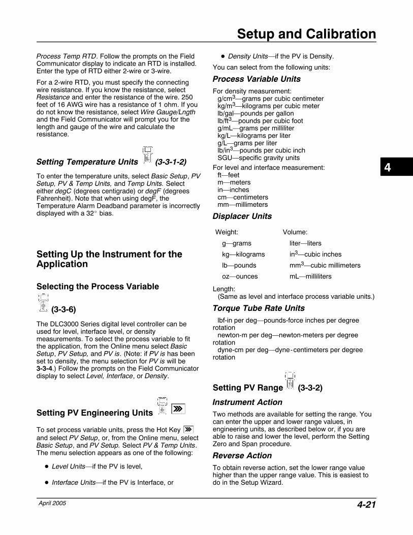
Setup and Calibration
April 2005 4-21
Process Temp RTD. Follow the prompts on the FieldCommunicator display to indicate an RTD is installed.Enter the type of RTD either 2-wire or 3-wire.
For a 2-wire RTD, you must specify the connectingwire resistance. If you know the resistance, selectResistance and enter the resistance of the wire. 250feet of 16 AWG wire has a resistance of 1 ohm. If youdo not know the resistance, select Wire Gauge/Lngthand the Field Communicator will prompt you for thelength and gauge of the wire and calculate theresistance.
Setting Temperature Units (3-3-1-2)
To enter the temperature units, select Basic Setup, PVSetup, PV & Temp Units, and Temp Units. Selecteither degC (degrees centigrade) or degF (degreesFahrenheit). Note that when using degF, theTemperature Alarm Deadband parameter is incorrectlydisplayed with a 32� bias.
Setting Up the Instrument for theApplication
Selecting the Process Variable
(3-3-6)
The DLC3000 Series digital level controller can beused for level, interface level, or densitymeasurements. To select the process variable to fitthe application, from the Online menu select BasicSetup, PV Setup, and PV is. (Note: if PV is has beenset to density, the menu selection for PV is will be3-3-4.) Follow the prompts on the Field Communicatordisplay to select Level, Interface, or Density.
Setting PV Engineering Units
To set process variable units, press the Hot Key and select PV Setup, or, from the Online menu, selectBasic Setup, and PV Setup. Select PV & Temp Units.The menu selection appears as one of the following:
� Level Units—if the PV is level,
� Interface Units—if the PV is Interface, or
� Density Units—if the PV is Density.
You can select from the following units:
Process Variable UnitsFor density measurement:
g/cm3—grams per cubic centimeterkg/m3—kilograms per cubic meterlb/gal—pounds per gallonlb/ft3—pounds per cubic footg/mL—grams per milliliterkg/L—kilograms per literg/L—grams per literlb/in3—pounds per cubic inchSGU—specific gravity units
For level and interface measurement:ft—feetm—metersin—inchescm—centimetersmm—millimeters
Displacer Units
Weight: Volume:
g—grams liter—liters
kg—kilograms in3—cubic inches
lb—pounds mm3—cubic millimeters
oz—ounces mL—milliliters
Length:(Same as level and interface process variable units.)
Torque Tube Rate Unitslbf-in per deg—pounds-force inches per degree
rotationnewton-m per deg—newton-meters per degree
rotationdyne-cm per deg—dyne-centimeters per degree
rotation
Setting PV Range (3-3-2)
Instrument ActionTwo methods are available for setting the range. Youcan enter the upper and lower range values, inengineering units, as described below or, if you areable to raise and lower the level, perform the SettingZero and Span procedure.
Reverse ActionTo obtain reverse action, set the lower range valuehigher than the upper range value. This is easiest todo in the Setup Wizard.
4
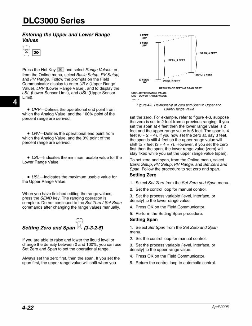
DLC3000 Series
April 20054-22
Entering the Upper and Lower RangeValues
Press the Hot Key and select Range Values, or,from the Online menu, select Basic Setup, PV Setup,and PV Range. Follow the prompts on the FieldCommunicator display to enter URV (Upper RangeValue), LRV (Lower Range Value), and to display theLSL (Lower Sensor Limit), and USL (Upper SensorLimit).
� URV—Defines the operational end point fromwhich the Analog Value, and the 100% point of thepercent range are derived.
� LRV—Defines the operational end point fromwhich the Analog Value, and the 0% point of thepercent range are derived.
� LSL—Indicates the minimum usable value for theLower Range Value.
� USL—Indicates the maximum usable value forthe Upper Range Value.
When you have finished editing the range values,press the SEND key. The ranging operation iscomplete. Do not continued to the Set Zero / Set Spancommands after changing the range values manually.
Setting Zero and Span (3-3-2-5)
If you are able to raise and lower the liquid level orchange the density between 0 and 100%, you can useSet Zero and Span to set the operational range.
Always set the zero first, then the span. If you set thespan first, the upper range value will shift when you
Figure 4-3. Relationship of Zero and Span to Upper andLower Range Value
(2 FEET)LRV
6 FEETURV
SPAN, 4 FEET
ZERO, 2 FEET
SPAN, 4 FEET
ZERO, 3 FEET
7 FEETURV
RESULTS OF SETTING SPAN FIRST
URV—UPPER RANGE VALUELRV—LOWER RANGE VALUEE0367 / IL
set the zero. For example, refer to figure 4-3, supposethe zero is set to 2 feet from a previous ranging. If youset the span at 4 feet then the lower range value is 2feet and the upper range value is 6 feet. The span is 4feet (6 - 2 = 4). If you now set the zero at, say 3 feet,the span is still 4 feet so the upper range value willshift to 7 feet (3 + 4 = 7). However, if you set the zerofirst then the span, the lower range value (zero) willstay fixed while you set the upper range value (span).
To set zero and span, from the Online menu, selectBasic Setup, PV Setup, PV Range, and Set Zero andSpan. Follow the procedure to set zero and span.
Setting Zero
1. Select Set Zero from the Set Zero and Span menu.
2. Set the control loop for manual control.
3. Set the process variable (level, interface, ordensity) to the lower range value.
4. Press OK on the Field Communicator.
5. Perform the Setting Span procedure.
Setting Span
1. Select Set Span from the Set Zero and Spanmenu.
2. Set the control loop for manual control.
3. Set the process variable (level, interface, ordensity) to the upper range value.
4. Press OK on the Field Communicator.
5. Return the control loop to automatic control.
4
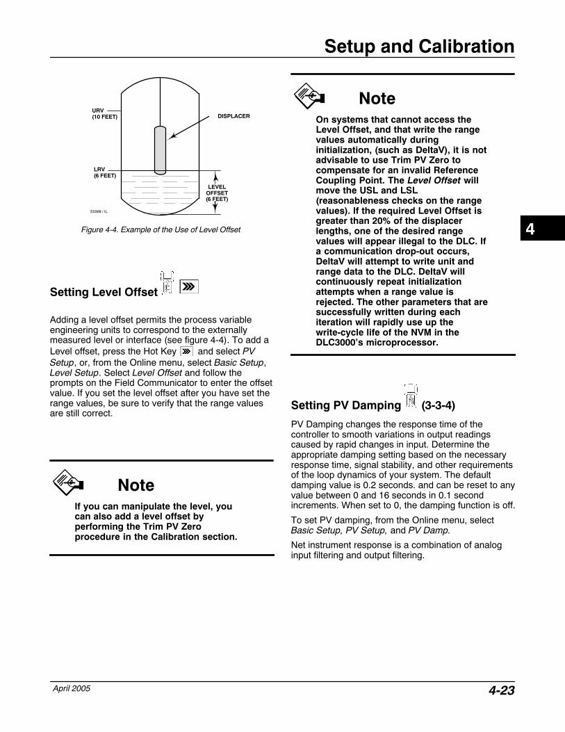
Setup and Calibration
April 2005 4-23
Figure 4-4. Example of the Use of Level Offset
LEVELOFFSET(6 FEET)
URV(10 FEET)
LRV(6 FEET)
E0368 / IL
DISPLACER
Setting Level Offset
Adding a level offset permits the process variableengineering units to correspond to the externallymeasured level or interface (see figure 4-4). To add aLevel offset, press the Hot Key and select PVSetup, or, from the Online menu, select Basic Setup,Level Setup. Select Level Offset and follow theprompts on the Field Communicator to enter the offsetvalue. If you set the level offset after you have set therange values, be sure to verify that the range valuesare still correct.
NoteIf you can manipulate the level, youcan also add a level offset byperforming the Trim PV Zeroprocedure in the Calibration section.
NoteOn systems that cannot access theLevel Offset, and that write the rangevalues automatically duringinitialization, (such as DeltaV), it is notadvisable to use Trim PV Zero tocompensate for an invalid ReferenceCoupling Point. The Level Offset willmove the USL and LSL(reasonableness checks on the rangevalues). If the required Level Offset isgreater than 20% of the displacerlengths, one of the desired rangevalues will appear illegal to the DLC. Ifa communication drop-out occurs,DeltaV will attempt to write unit andrange data to the DLC. DeltaV willcontinuously repeat initializationattempts when a range value isrejected. The other parameters that aresuccessfully written during eachiteration will rapidly use up thewrite-cycle life of the NVM in theDLC3000’s microprocessor.
Setting PV Damping (3-3-4)
PV Damping changes the response time of thecontroller to smooth variations in output readingscaused by rapid changes in input. Determine theappropriate damping setting based on the necessaryresponse time, signal stability, and other requirementsof the loop dynamics of your system. The defaultdamping value is 0.2 seconds. and can be reset to anyvalue between 0 and 16 seconds in 0.1 secondincrements. When set to 0, the damping function is off.
To set PV damping, from the Online menu, selectBasic Setup, PV Setup, and PV Damp.
Net instrument response is a combination of analoginput filtering and output filtering.
4
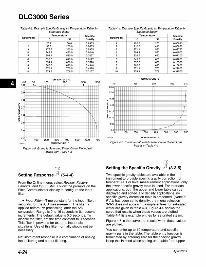
DLC3000 Series
April 20054-24
Table 4-3. Example Specific Gravity vs Temperature Table forSaturated Water
Data PointTemperature Specific
Data Point�C �F
SpecificGravity
12345
26.793.3176.7248.9304.4
80.0200.0350.0480.0580.0
0.99850.96550.89350.80400.7057
6789
10
337.8354.4365.6371.1374.7
640.0670.0690.0700.0706.5
0.61970.55700.49400.43900.3157
Figure 4-5. Example Saturated Water Curve Plotted withValues from Table 4-3
0.3
0.4
0.5
0.6
0.7
0.8
0.9
1.0
0 100 200 300 400 500 600 700TEMPERATURE �F
SP
EC
IFIC
GR
AV
ITY
100 200 300-18 30 380TEMPERATURE �C
E0369 / IL
Setting Response (5-4-4)
From the Online menu, select Review, FactorySettings, and Input Filter. Follow the prompts on theField Communicator display to configure the inputfilter.
� Input Filter—Time constant for the input filter, inseconds, for the A/D measurement. The filter isapplied before PV processing, after the A/Dconversion. Range is 0 to 16 seconds in 0.1 secondincrements. The default value is 0.0 seconds. Todisable the filter, set the time constant to 0 seconds.This filter is provided for extreme input noisesituations. Use of this filter normally should not benecessary.
Net instrument response is a combination of analoginput filtering and output filtering.
Table 4-4. Example Specific Gravity vs Temperature Table forSaturated Steam
Data PointTemperature Specific
Data Point�C �F
SpecificGravity
12345
126.7210.0271.1304.4326.7
260410520580620
0.000950.008500.027600.049000.07200
6789
10
343.3357.8365.6371.1374.4
650676690700706
0.098000.135000.168000.210000.31570
Figure 4-6. Example Saturated Steam Curve Plotted fromValues in Table 4-4
0.0
0.05
0.10
0.15
0.20
0.25
0.30
0.35
0 100 200 300 400 500 600 700
SP
EC
IFIC
GR
AV
ITY
TEMPERATURE �F
-18 100 200 300 375
TEMPERATURE �C
E0370 / IL
Setting the Specific Gravity (3-3-5)
Two specific gravity tables are available in theinstrument to provide specific gravity correction fortemperature. For level measurement applications, onlythe lower specific gravity table is used. For interfaceapplications, both the upper and lower table can bedisplayed and edited. For density applications, nospecific gravity correction table is presented. (Note: ifPV is has been set to density, the menu selection3-3-5 does not appear.) Example entries for saturatedwater are given in table 4-3. Figure 4-5 shows thecurve that results when these values are plotted.Table 4-4 lists example entries for saturated steam.
Figure 4-6 is the curve that results when these valuesare plotted.
You can enter up to 10 temperature and specificgravity pairs in the table. The table entry function isterminated by entering zero for the specific gravity.Keep this in mind when setting up a table for a upper
4
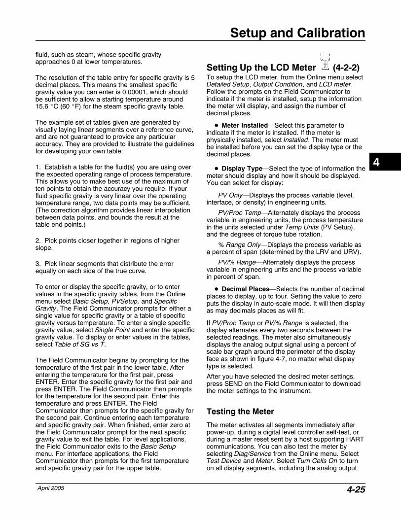
Setup and Calibration
April 2005 4-25
fluid, such as steam, whose specific gravityapproaches 0 at lower temperatures.
The resolution of the table entry for specific gravity is 5decimal places. This means the smallest specificgravity value you can enter is 0.00001, which shouldbe sufficient to allow a starting temperature around15.6 �C (60 �F) for the steam specific gravity table.
The example set of tables given are generated byvisually laying linear segments over a reference curve,and are not guaranteed to provide any particularaccuracy. They are provided to illustrate the guidelinesfor developing your own table:
1. Establish a table for the fluid(s) you are using overthe expected operating range of process temperature.This allows you to make best use of the maximum often points to obtain the accuracy you require. If yourfluid specific gravity is very linear over the operatingtemperature range, two data points may be sufficient.(The correction algorithm provides linear interpolationbetween data points, and bounds the result at thetable end points.)
2. Pick points closer together in regions of higherslope.
3. Pick linear segments that distribute the errorequally on each side of the true curve.
To enter or display the specific gravity, or to entervalues in the specific gravity tables, from the Onlinemenu select Basic Setup, PVSetup, and SpecificGravity. The Field Communicator prompts for either asingle value for specific gravity or a table of specificgravity versus temperature. To enter a single specificgravity value, select Single Point and enter the specificgravity value. To display or enter values in the tables,select Table of SG vs T.
The Field Communicator begins by prompting for thetemperature of the first pair in the lower table. Afterentering the temperature for the first pair, pressENTER. Enter the specific gravity for the first pair andpress ENTER. The Field Communicator then promptsfor the temperature for the second pair. Enter thistemperature and press ENTER. The FieldCommunicator then prompts for the specific gravity forthe second pair. Continue entering each temperatureand specific gravity pair. When finished, enter zero atthe Field Communicator prompt for the next specificgravity value to exit the table. For level applications,the Field Communicator exits to the Basic Setupmenu. For interface applications, the FieldCommunicator then prompts for the first temperatureand specific gravity pair for the upper table.
Setting Up the LCD Meter (4-2-2) To setup the LCD meter, from the Online menu selectDetailed Setup, Output Condition, and LCD meter.Follow the prompts on the Field Communicator toindicate if the meter is installed, setup the informationthe meter will display, and assign the number ofdecimal places.
� Meter Installed—Select this parameter toindicate if the meter is installed. If the meter isphysically installed, select Installed. The meter mustbe installed before you can set the display type or thedecimal places.
� Display Type—Select the type of information themeter should display and how it should be displayed.You can select for display:
PV Only—Displays the process variable (level,interface, or density) in engineering units.
PV/Proc Temp—Alternately displays the processvariable in engineering units, the process temperaturein the units selected under Temp Units (PV Setup),and the degrees of torque tube rotation.
% Range Only—Displays the process variable asa percent of span (determined by the LRV and URV).
PV/% Range—Alternately displays the processvariable in engineering units and the process variablein percent of span.
� Decimal Places—Selects the number of decimalplaces to display, up to four. Setting the value to zeroputs the display in auto-scale mode. It will then displayas may decimals places as will fit.
If PV/Proc Temp or PV/% Range is selected, thedisplay alternates every two seconds between theselected readings. The meter also simultaneouslydisplays the analog output signal using a percent ofscale bar graph around the perimeter of the displayface as shown in figure 4-7, no matter what displaytype is selected.
After you have selected the desired meter settings,press SEND on the Field Communicator to downloadthe meter settings to the instrument.
Testing the Meter
The meter activates all segments immediately afterpower-up, during a digital level controller self-test, orduring a master reset sent by a host supporting HARTcommunications. You can also test the meter byselecting Diag/Service from the Online menu. SelectTest Device and Meter. Select Turn Cells On to turnon all display segments, including the analog output
4
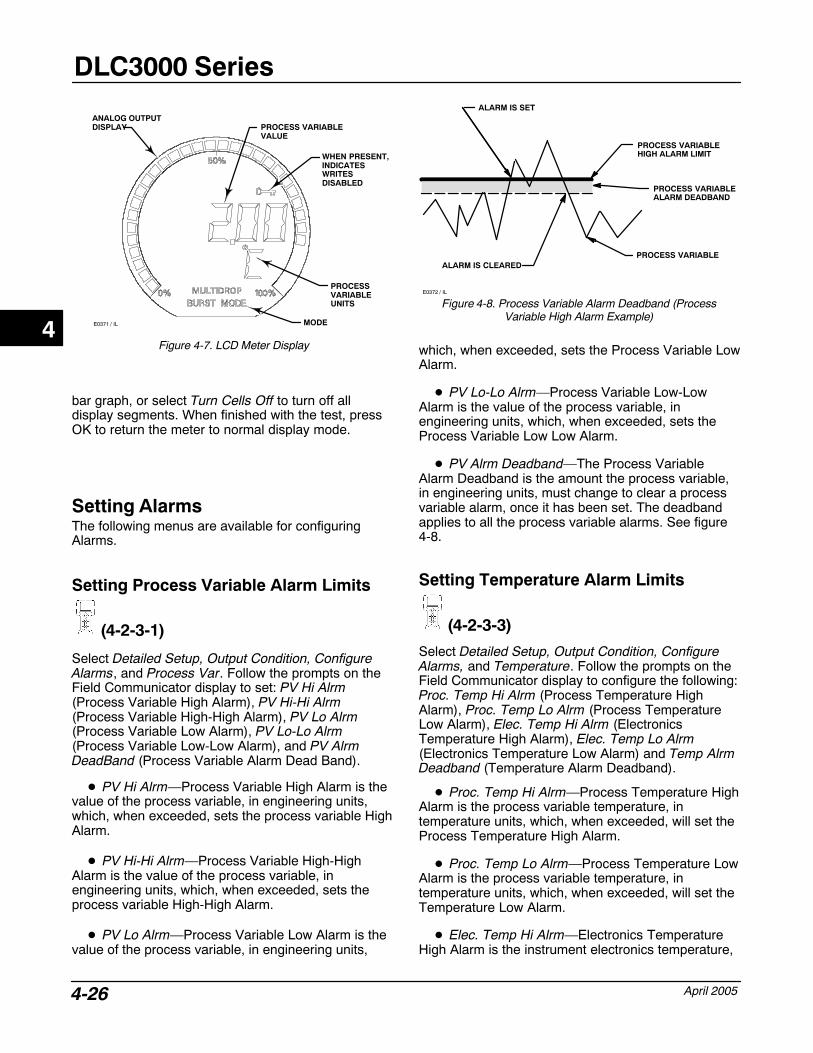
DLC3000 Series
April 20054-26
Figure 4-7. LCD Meter Display
WHEN PRESENT, INDICATESWRITES DISABLED
PROCESS VARIABLE VALUE
MODE
PROCESS VARIABLEUNITS
ANALOG OUTPUT DISPLAY
E0371 / IL
bar graph, or select Turn Cells Off to turn off alldisplay segments. When finished with the test, pressOK to return the meter to normal display mode.
Setting AlarmsThe following menus are available for configuringAlarms.
Setting Process Variable Alarm Limits
(4-2-3-1)
Select Detailed Setup, Output Condition, ConfigureAlarms, and Process Var. Follow the prompts on theField Communicator display to set: PV Hi Alrm(Process Variable High Alarm), PV Hi-Hi Alrm(Process Variable High-High Alarm), PV Lo Alrm(Process Variable Low Alarm), PV Lo-Lo Alrm(Process Variable Low-Low Alarm), and PV AlrmDeadBand (Process Variable Alarm Dead Band).
� PV Hi Alrm—Process Variable High Alarm is thevalue of the process variable, in engineering units,which, when exceeded, sets the process variable HighAlarm.
� PV Hi-Hi Alrm—Process Variable High-HighAlarm is the value of the process variable, inengineering units, which, when exceeded, sets theprocess variable High-High Alarm.
� PV Lo Alrm—Process Variable Low Alarm is thevalue of the process variable, in engineering units,
ALARM IS CLEARED
ALARM IS SET
PROCESS VARIABLEHIGH ALARM LIMIT
PROCESS VARIABLEALARM DEADBAND
E0372 / IL
Figure 4-8. Process Variable Alarm Deadband (ProcessVariable High Alarm Example)
PROCESS VARIABLE
which, when exceeded, sets the Process Variable LowAlarm.
� PV Lo-Lo Alrm—Process Variable Low-LowAlarm is the value of the process variable, inengineering units, which, when exceeded, sets theProcess Variable Low Low Alarm.
� PV Alrm Deadband—The Process VariableAlarm Deadband is the amount the process variable,in engineering units, must change to clear a processvariable alarm, once it has been set. The deadbandapplies to all the process variable alarms. See figure4-8.
Setting Temperature Alarm Limits
(4-2-3-3)
Select Detailed Setup, Output Condition, ConfigureAlarms, and Temperature. Follow the prompts on theField Communicator display to configure the following:Proc. Temp Hi Alrm (Process Temperature HighAlarm), Proc. Temp Lo Alrm (Process TemperatureLow Alarm), Elec. Temp Hi Alrm (ElectronicsTemperature High Alarm), Elec. Temp Lo Alrm(Electronics Temperature Low Alarm) and Temp AlrmDeadband (Temperature Alarm Deadband).
� Proc. Temp Hi Alrm—Process Temperature HighAlarm is the process variable temperature, intemperature units, which, when exceeded, will set theProcess Temperature High Alarm.
� Proc. Temp Lo Alrm—Process Temperature LowAlarm is the process variable temperature, intemperature units, which, when exceeded, will set theTemperature Low Alarm.
� Elec. Temp Hi Alrm—Electronics TemperatureHigh Alarm is the instrument electronics temperature,
4
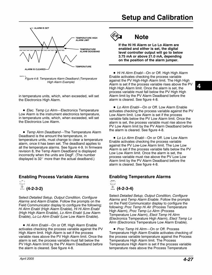
Setup and Calibration
April 2005 4-27
ALARM IS CLEARED
ALARM IS SET
TEMPERATURE HIGHALARM LIMIT
TEMPERATUREALARM DEADBAND
E0373 / IL
Figure 4-9. Temperature Alarm Deadband (TemperatureHigh Alarm Example)
TEMPERATURE
in temperature units, which, when exceeded, will setthe Electronics High Alarm.
� Elec. Temp Lo Alrm—Electronics TemperatureLow Alarm is the instrument electronics temperature,in temperature units, which, when exceeded, will setthe Electronics Low Alarm.
� Temp Alrm Deadband—The Temperature AlarmDeadband is the amount the temperature, intemperature units, must change to clear a temperaturealarm, once it has been set. The deadband applies toall the temperature alarms. See figure 4-9. In firmwarerevision 8, the Temp Alarm Deadband is displayedincorrectly when the units are DegF. (The numberdisplayed is 32� more than the actual deadband.)
Enabling Process Variable Alarms
(4-2-3-2)
Select Detailed Setup, Output Condition, ConfigureAlarms and Alarm Enable. Follow the prompts on theField Communicator display to configure the following:Hi Alrm Enabl (High Alarm Enable), Hi Hi Alrm Enabl(High High Alarm Enable), Lo Alrm Enabl (Low AlarmEnable), Lo Lo Alrm Enabl (Low Low Alarm Enable).
� Hi Alrm Enabl—On or Off. High Alarm Enableactivates checking the process variable against the PVHigh Alarm limit. High Alarm is set if the processvariable rises above the PV High Alarm limit. Once thealarm is set, the process variable must fall below thePV High Alarm limit by the PV Alarm Deadband beforethe alarm is cleared. See figure 4-8.
NoteIf the Hi Hi Alarm or Lo Lo Alarm areenabled and either is set, the digitallevel controller output will go to below3.75 mA or above 21.0 mA, dependingon the position of the alarm jumper.
� Hi Hi Alrm Enabl—On or Off. High High AlarmEnable activates checking the process variableagainst the PV High-High Alarm limit. The High HighAlarm is set if the process variable rises above the PVHigh High Alarm limit. Once the alarm is set, theprocess variable must fall below the PV High HighAlarm limit by the PV Alarm Deadband before thealarm is cleared. See figure 4-8.
� Lo Alrm Enabl—On or Off. Low Alarm Enableactivates checking the process variable against the PVLow Alarm limit. Low Alarm is set if the processvariable falls below the PV Low Alarm limit. Once thealarm is set, the process variable must rise above thePV Low Alarm limit by the PV Alarm Deadband beforethe alarm is cleared. See figure 4-8.
� Lo Lo Alrm Enabl—On or Off. Low Low AlarmEnable activates checking the process variableagainst the PV Low-Low Alarm limit. The Low LowAlarm is set if the process variable falls below the PVLow Low Alarm limit. Once the alarm is set, theprocess variable must rise above the PV Low LowAlarm limit by the PV Alarm Deadband before thealarm is cleared. See figure 4-8.
Enabling Temperature Alarms
(4-2-3-4)
Select Detailed Setup, Output Condition, ConfigureAlarms and Temp Alarm Enable. Follow the promptson the Field Communicator display to configure thefollowing: Proc Temp Hi Alr (Process TemperatureHigh Alarm), Proc Temp Lo Alrm (ProcessTemperature Low Alarm), Elect Temp Hi Alrm(Electronics Temperature High Alarm), Elect Temp LoAlrm (Electronics Temperature Low Alarm Enable).
� Proc Temp Hi Alrm—On or Off. ProcessTemperature High Alarm Enable activates checking ofthe process variable temperature against the ProcessTemperature High Alarm limit. The ProcessTemperature High Alarm is set if the process variabletemperature rises above the Process Temperature
4
DLC3000 Series
April 20054-28
High Alarm limit. Once the alarm is set, the processvariable temperature must fall below the ProcessTemperature High Alarm limit by the TemperatureAlarm Deadband before the alarm is cleared. Seefigure 4-9.
� Proc Temp Lo Alrm—On or Off. ProcessTemperature Low Alarm Enable activates checking ofthe process variable temperature against the ProcessTemperature Low Alarm limit. Process TemperatureLow Alarm is set if the process variable temperaturefalls below the Process Temperature Low Alarm limit.Once the alarm is set, the process variabletemperature must rise above the ProcessTemperature Low Alarm limit by the TemperatureAlarm Deadband before the alarm is cleared. Seefigure 4-9.
� Elect Temp Hi Alrm—On or Off. ElectronicsTemperature High Alarm Enable activates checking ofthe instrument electronics temperature against theElectronics Temperature High Alarm limit. ElectronicsTemperature High Alarm is set if the instrumentelectronics temperature rises above the ElectronicsTemperature High Alarm limit. Once the alarm is set,the instrument electronics temperature must fall belowthe Electronics Temperature High Alarm limit by theTemperature Alarm Deadband before the alarm iscleared. See figure 4-9.
� Elect Temp Lo Alrm—On or Off. ElectronicsTemperature Low Alarm Enable activates checking ofthe instrument electronics temperature against theElectronics Temperature Low Alarm limit. ElectronicsTemperature Low Alarm is set if the instrumentelectronics temperature falls below the ElectronicsTemperature Low Alarm limit. Once the alarm is set,the instrument electronics temperature must riseabove the Electronics Temperature Low Alarm limit bythe Temperature Alarm Deadband before the alarm iscleared. See figure 4-9.
Entering HART� Information
(4-3-1)From the Online menu select Detailed Setup, DeviceInformation, and HART. Follow the prompts on theField Communicator display to enter or viewinformation in the following fields: HART Tag, PollingAddress, Message, Descriptor, and Date.
� HART Tag—The HART tag is the easiest way toidentify and distinguish between controllers inmulti-controller environments. Use the HART tag tolabel controllers electronically according to therequirements of your application. The tag you define isautomatically displayed when a HART-basedcommunicator establishes contact with the controllerat power-up. The tag may be up to eight characterslong and has no impact on the primary variablereadings of the controller.
� Polling Address—If the digital level controller isused in a point-to-point configuration, the PollingAddress is 0. When several devices are connected inthe same loop, each device must be assigned aunique polling address. The Polling Address may beset to a value between 0 and 15.
For the Field Communicator to be able tocommunicate with a device whose polling address isnot 0, it must be configured to automatically search forall or specific connected devices. For information onconfiguring the Field Communicator for automaticpolling, see the Model 375 Field Communicator Basicssection, Appendix A.
� Message—Message provides the most specificuser-defined means for identifying individualcontrollers in multi-controller environments. it allowsfor 32 characters of information and is stored with theother configuration data. Message has no impact onthe operation of the controller or the HART-basedcommunicator.
� Descriptor—The Descriptor provides a longeruser-defined electronic label to assist with morespecific controller identification that is available withthe HART tag. The descriptor may be up to 16characters long and has no impact on the operation ofthe controller or HART-based communicator.
� Date—Date is a user-defined variable thatprovides a place to save the date of the last revision ofconfiguration or calibration information. It has noimpact on the operation of the controller or FieldCommunicator. Enter a date with the formatMM/DD/YY.
4
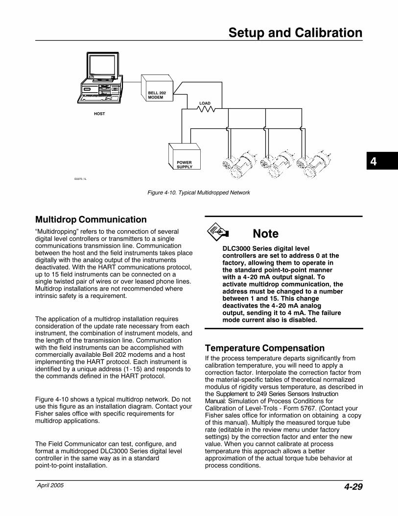
Setup and Calibration
April 2005 4-29
Figure 4-10. Typical Multidropped Network
E0375 / IL
HOST
BELL 202MODEM
POWERSUPPLY
LOAD
Multidrop Communication “Multidropping” refers to the connection of severaldigital level controllers or transmitters to a singlecommunications transmission line. Communicationbetween the host and the field instruments takes placedigitally with the analog output of the instrumentsdeactivated. With the HART communications protocol,up to 15 field instruments can be connected on asingle twisted pair of wires or over leased phone lines.Multidrop installations are not recommended whereintrinsic safety is a requirement.
The application of a multidrop installation requiresconsideration of the update rate necessary from eachinstrument, the combination of instrument models, andthe length of the transmission line. Communicationwith the field instruments can be accomplished withcommercially available Bell 202 modems and a hostimplementing the HART protocol. Each instrument isidentified by a unique address (1-15) and responds tothe commands defined in the HART protocol.
Figure 4-10 shows a typical multidrop network. Do notuse this figure as an installation diagram. Contact yourFisher sales office with specific requirements formultidrop applications.
The Field Communicator can test, configure, andformat a multidropped DLC3000 Series digital levelcontroller in the same way as in a standardpoint-to-point installation.
NoteDLC3000 Series digital levelcontrollers are set to address 0 at thefactory, allowing them to operate inthe standard point-to-point mannerwith a 4-20 mA output signal. Toactivate multidrop communication, theaddress must be changed to a numberbetween 1 and 15. This changedeactivates the 4-20 mA analogoutput, sending it to 4 mA. The failuremode current also is disabled.
Temperature CompensationIf the process temperature departs significantly fromcalibration temperature, you will need to apply acorrection factor. Interpolate the correction factor fromthe material-specific tables of theoretical normalizedmodulus of rigidity versus temperature, as described inthe Supplement to 249 Series Sensors InstructionManual: Simulation of Process Conditions forCalibration of Level-Trols - Form 5767. (Contact yourFisher sales office for information on obtaining a copyof this manual). Multiply the measured torque tuberate (editable in the review menu under factorysettings) by the correction factor and enter the newvalue. When you cannot calibrate at processtemperature this approach allows a betterapproximation of the actual torque tube behavior atprocess conditions.
4
DLC3000 Series
April 20054-30
4
Troubleshooting and Maintenance
April 2005 5-1
5-5
Section 5 Troubleshooting & MaintenanceDiagnostic Messages 5-3. . . . . . . . . . . . . . . . . . . . . . . . . . . . . . . . . . . . . . . . . . . . . . .
Viewing Device InformationViewing Process Variable Information 5-5. . . . . . . . . . . . . . . . . . . . . . . . . . . . . . . .
Process VariableElectronics TemperatureProcess Variable Range
Viewing Output Information 5-5. . . . . . . . . . . . . . . . . . . . . . . . . . . . . . . . . . . . . . . . . . . .
Process Variable
Analog Output
% RangeAlarm Jumper
Measuring Specific Gravity 5-6. . . . . . . . . . . . . . . . . . . . . . . . . . . . . . . . . . . . . . . . . . . . .
Trending 5-6. . . . . . . . . . . . . . . . . . . . . . . . . . . . . . . . . . . . . . . . . . . . . . . . . . . . . . . . . . . . . . . . .
Viewing the Device ID 5-7. . . . . . . . . . . . . . . . . . . . . . . . . . . . . . . . . . . . . . . . . . . . . . . . . . .
Viewing Version Information 5-7. . . . . . . . . . . . . . . . . . . . . . . . . . . . . . . . . . . . . . . . . . .
Field Device Revision
Device Description RevisionSoftware RevisionHardware RevisionUniversal Revision
Viewing Serial Number Information 5-7. . . . . . . . . . . . . . . . . . . . . . . . . . . . . . . . . . . .
Displacer Serial NumberFinal Assembly NumberInstrument Serial Number
Viewing Process and Temperature Alarms 5-7. . . . . . . . . . . . . . . . . . . . . . . . . . .
Viewing Hardware Alarms 5-8. . . . . . . . . . . . . . . . . . . . . . . . . . . . . . . . . . . . . . . . . . . . . .
Viewing Instrument Status 5-8. . . . . . . . . . . . . . . . . . . . . . . . . . . . . . . . . . . . . . . . . . . . .
Hardware Diagnostics 5-5. . . . . . . . . . . . . . . . . . . . . . . . . . . . . . . . . . . . . . . . . . . . . . . . . .
Test Terminals 5-5. . . . . . . . . . . . . . . . . . . . . . . . . . . . . . . . . . . . . . . . . . . . . . . . . . . . . . . . . .
Removing the Digital LevelController from the Sensor 5-9. . . . . . . . . . . . . . . . . . . . . . . . . . . . . . . . . . . . . . . . . . . .
Removing the Type DLC3010Digital Level Controller from a 249 Series Sensor 5-9. . . . . . . . . . . . . . . . . . . . . . . . .
5
DLC3000 Series
April 20055-2
249 Series Sensor in Standard Temperature Application 5-9. . . . . . . . . . . . . . . . . . . . . . 249 Series Sensor in High Temperature Application 5-10. . . . . . . . . . . . . . . . . . . . . . . . . .
LCD Meter Assembly 5-11. . . . . . . . . . . . . . . . . . . . . . . . . . . . . . . . . . . . . . . . . . . . . . . . . . .
Removing the LCD Meter Assembly 5-11. . . . . . . . . . . . . . . . . . . . . . . . . . . . . . . . . . . . . .
Replacing the LCD Meter Assembly 5-11. . . . . . . . . . . . . . . . . . . . . . . . . . . . . . . . . . . . . .
Electronics Module 5-12. . . . . . . . . . . . . . . . . . . . . . . . . . . . . . . . . . . . . . . . . . . . . . . . . . . . .
Removing the Electronics Module 5-12. . . . . . . . . . . . . . . . . . . . . . . . . . . . . . . . . . . . . . . .
Replacing the Electronics Module 5-13. . . . . . . . . . . . . . . . . . . . . . . . . . . . . . . . . . . . . . . .
Terminal Box 5-13. . . . . . . . . . . . . . . . . . . . . . . . . . . . . . . . . . . . . . . . . . . . . . . . . . . . . . . . . . . .
Removing the Terminal Box 5-13. . . . . . . . . . . . . . . . . . . . . . . . . . . . . . . . . . . . . . . . . . . . . .
Replacing the Terminal Box 5-14. . . . . . . . . . . . . . . . . . . . . . . . . . . . . . . . . . . . . . . . . . . . . .
Removing and Replacing the Inner Guideand Access Handle Assembly 5-14. . . . . . . . . . . . . . . . . . . . . . . . . . . . . . . . . . . . . . . . .
Lever Assembly 5-15. . . . . . . . . . . . . . . . . . . . . . . . . . . . . . . . . . . . . . . . . . . . . . . . . . . . . . . . .
Removing the Lever Assembly 5-15. . . . . . . . . . . . . . . . . . . . . . . . . . . . . . . . . . . . . . . . . . .
Replacing the Lever Assembly 5-15. . . . . . . . . . . . . . . . . . . . . . . . . . . . . . . . . . . . . . . . . . .
Packing for Shipment 5-16. . . . . . . . . . . . . . . . . . . . . . . . . . . . . . . . . . . . . . . . . . . . . . . . . . .
5
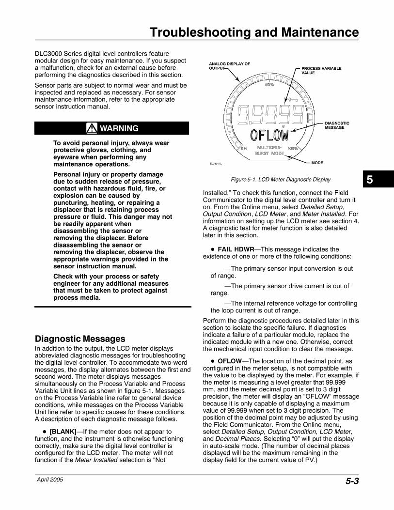
Troubleshooting and Maintenance
April 2005 5-3
DLC3000 Series digital level controllers featuremodular design for easy maintenance. If you suspecta malfunction, check for an external cause beforeperforming the diagnostics described in this section.
Sensor parts are subject to normal wear and must beinspected and replaced as necessary. For sensormaintenance information, refer to the appropriatesensor instruction manual.
WARNING
To avoid personal injury, always wearprotective gloves, clothing, andeyeware when performing anymaintenance operations.
Personal injury or property damagedue to sudden release of pressure,contact with hazardous fluid, fire, orexplosion can be caused bypuncturing, heating, or repairing adisplacer that is retaining processpressure or fluid. This danger may notbe readily apparent whendisassembling the sensor orremoving the displacer. Beforedisassembling the sensor orremoving the displacer, observe theappropriate warnings provided in thesensor instruction manual.
Check with your process or safetyengineer for any additional measuresthat must be taken to protect againstprocess media.
Diagnostic Messages In addition to the output, the LCD meter displaysabbreviated diagnostic messages for troubleshootingthe digital level controller. To accommodate two-wordmessages, the display alternates between the first andsecond word. The meter displays messagessimultaneously on the Process Variable and ProcessVariable Unit lines as shown in figure 5-1. Messageson the Process Variable line refer to general deviceconditions, while messages on the Process VariableUnit line refer to specific causes for these conditions.A description of each diagnostic message follows.
� [BLANK]—If the meter does not appear tofunction, and the instrument is otherwise functioningcorrectly, make sure the digital level controller isconfigured for the LCD meter. The meter will notfunction if the Meter Installed selection is “Not
Figure 5-1. LCD Meter Diagnostic Display
DIAGNOSTIC MESSAGE
PROCESS VARIABLE VALUE
MODE
ANALOG DISPLAY OFOUTPUT
E0380 / IL
Installed.” To check this function, connect the FieldCommunicator to the digital level controller and turn iton. From the Online menu, select Detailed Setup,Output Condition, LCD Meter, and Meter Installed. Forinformation on setting up the LCD meter see section 4.A diagnostic test for meter function is also detailedlater in this section.
� FAIL HDWR—This message indicates theexistence of one or more of the following conditions:
—The primary sensor input conversion is outof range.
—The primary sensor drive current is out ofrange.
—The internal reference voltage for controllingthe loop current is out of range.
Perform the diagnostic procedures detailed later in thissection to isolate the specific failure. If diagnosticsindicate a failure of a particular module, replace theindicated module with a new one. Otherwise, correctthe mechanical input condition to clear the message.
� OFLOW—The location of the decimal point, asconfigured in the meter setup, is not compatible withthe value to be displayed by the meter. For example, ifthe meter is measuring a level greater that 99.999mm, and the meter decimal point is set to 3 digitprecision, the meter will display an “OFLOW” messagebecause it is only capable of displaying a maximumvalue of 99.999 when set to 3 digit precision. Theposition of the decimal point may be adjusted by usingthe Field Communicator. From the Online menu,select Detailed Setup, Output Condition, LCD Meter,and Decimal Places. Selecting “0” will put the displayin auto-scale mode. (The number of decimal placesdisplayed will be the maximum remaining in thedisplay field for the current value of PV.)
5
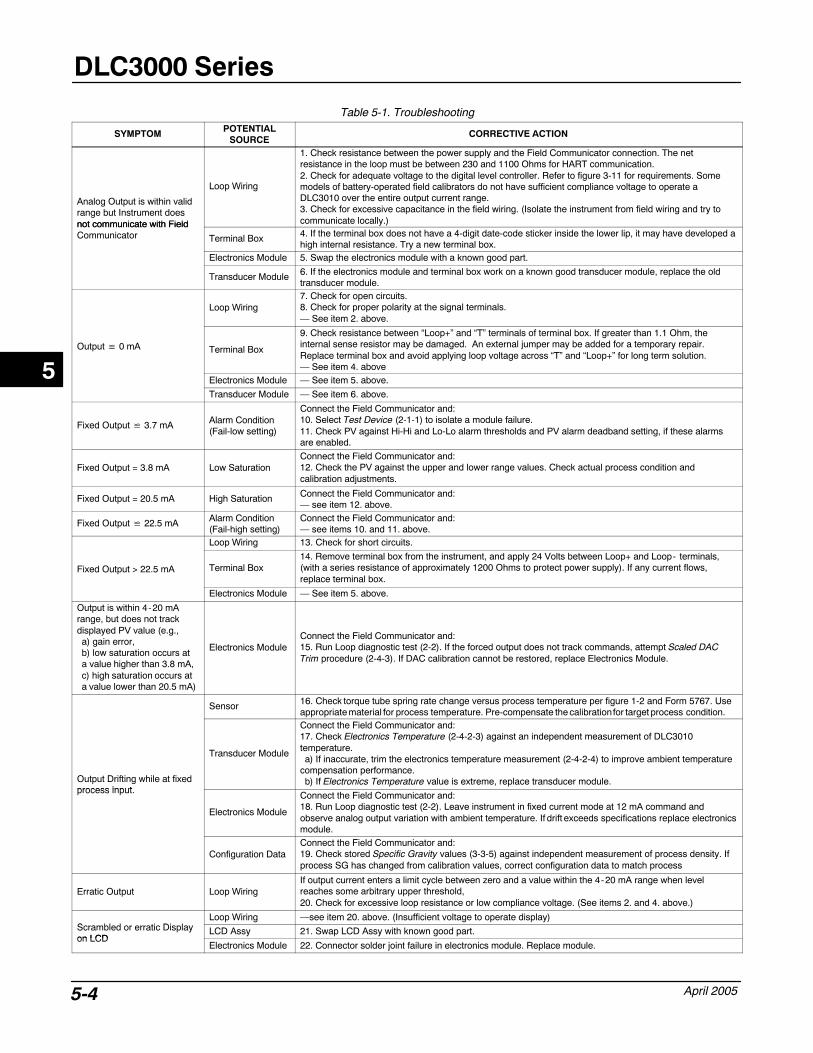
DLC3000 Series
April 20055-4
Table 5-1. Troubleshooting
SYMPTOM POTENTIALSOURCE
CORRECTIVE ACTION
Analog Output is within validrange but Instrument doesnot communicate with Field
Loop Wiring
1. Check resistance between the power supply and the Field Communicator connection. The netresistance in the loop must be between 230 and 1100 Ohms for HART communication. 2. Check for adequate voltage to the digital level controller. Refer to figure 3-11 for requirements. Somemodels of battery-operated field calibrators do not have sufficient compliance voltage to operate aDLC3010 over the entire output current range.3. Check for excessive capacitance in the field wiring. (Isolate the instrument from field wiring and try tocommunicate locally.)not communicate with Field
Communicator Terminal Box 4. If the terminal box does not have a 4-digit date-code sticker inside the lower lip, it may have developed ahigh internal resistance. Try a new terminal box.
Electronics Module 5. Swap the electronics module with a known good part.
Transducer Module 6. If the electronics module and terminal box work on a known good transducer module, replace the oldtransducer module.
Loop Wiring7. Check for open circuits.8. Check for proper polarity at the signal terminals.— See item 2. above.
Output � 0 mA Terminal Box
9. Check resistance between “Loop+” and “T” terminals of terminal box. If greater than 1.1 Ohm, theinternal sense resistor may be damaged. An external jumper may be added for a temporary repair.Replace terminal box and avoid applying loop voltage across “T” and “Loop+” for long term solution.— See item 4. above
Electronics Module — See item 5. above.
Transducer Module — See item 6. above.
Fixed Output � 3.7 mA Alarm Condition(Fail-low setting)
Connect the Field Communicator and:10. Select Test Device (2-1-1) to isolate a module failure.11. Check PV against Hi-Hi and Lo-Lo alarm thresholds and PV alarm deadband setting, if these alarmsare enabled.
Fixed Output = 3.8 mA Low SaturationConnect the Field Communicator and:12. Check the PV against the upper and lower range values. Check actual process condition andcalibration adjustments.
Fixed Output = 20.5 mA High Saturation Connect the Field Communicator and:— see item 12. above.
Fixed Output � 22.5 mA Alarm Condition(Fail-high setting)
Connect the Field Communicator and:— see items 10. and 11. above.
Loop Wiring 13. Check for short circuits.
Fixed Output > 22.5 mA Terminal Box14. Remove terminal box from the instrument, and apply 24 Volts between Loop+ and Loop- terminals,(with a series resistance of approximately 1200 Ohms to protect power supply). If any current flows,replace terminal box.
Electronics Module — See item 5. above.
Output is within 4-20 mArange, but does not trackdisplayed PV value (e.g.,a) gain error,b) low saturation occurs ata value higher than 3.8 mA,c) high saturation occurs ata value lower than 20.5 mA)
Electronics ModuleConnect the Field Communicator and:15. Run Loop diagnostic test (2-2). If the forced output does not track commands, attempt Scaled DACTrim procedure (2-4-3). If DAC calibration cannot be restored, replace Electronics Module.
Sensor 16. Check torque tube spring rate change versus process temperature per figure 1-2 and Form 5767. Useappropriate material for process temperature. Pre-compensate the calibration for target process condition.
Output Drifting while at fixedprocess input
Transducer Module
Connect the Field Communicator and:17. Check Electronics Temperature (2-4-2-3) against an independent measurement of DLC3010temperature.a) If inaccurate, trim the electronics temperature measurement (2-4-2-4) to improve ambient temperature
compensation performance.b) If Electronics Temperature value is extreme, replace transducer module.
process input.
Electronics Module
Connect the Field Communicator and:18. Run Loop diagnostic test (2-2). Leave instrument in fixed current mode at 12 mA command andobserve analog output variation with ambient temperature. If drift exceeds specifications replace electronicsmodule.
Configuration DataConnect the Field Communicator and:19. Check stored Specific Gravity values (3-3-5) against independent measurement of process density. Ifprocess SG has changed from calibration values, correct configuration data to match process
Erratic Output Loop WiringIf output current enters a limit cycle between zero and a value within the 4-20 mA range when levelreaches some arbitrary upper threshold,20. Check for excessive loop resistance or low compliance voltage. (See items 2. and 4. above.)
S bl d ti Di lLoop Wiring —see item 20. above. (Insufficient voltage to operate display)
Scrambled or erratic Displayon LCD
LCD Assy 21. Swap LCD Assy with known good part.on LCD
Electronics Module 22. Connector solder joint failure in electronics module. Replace module.
5
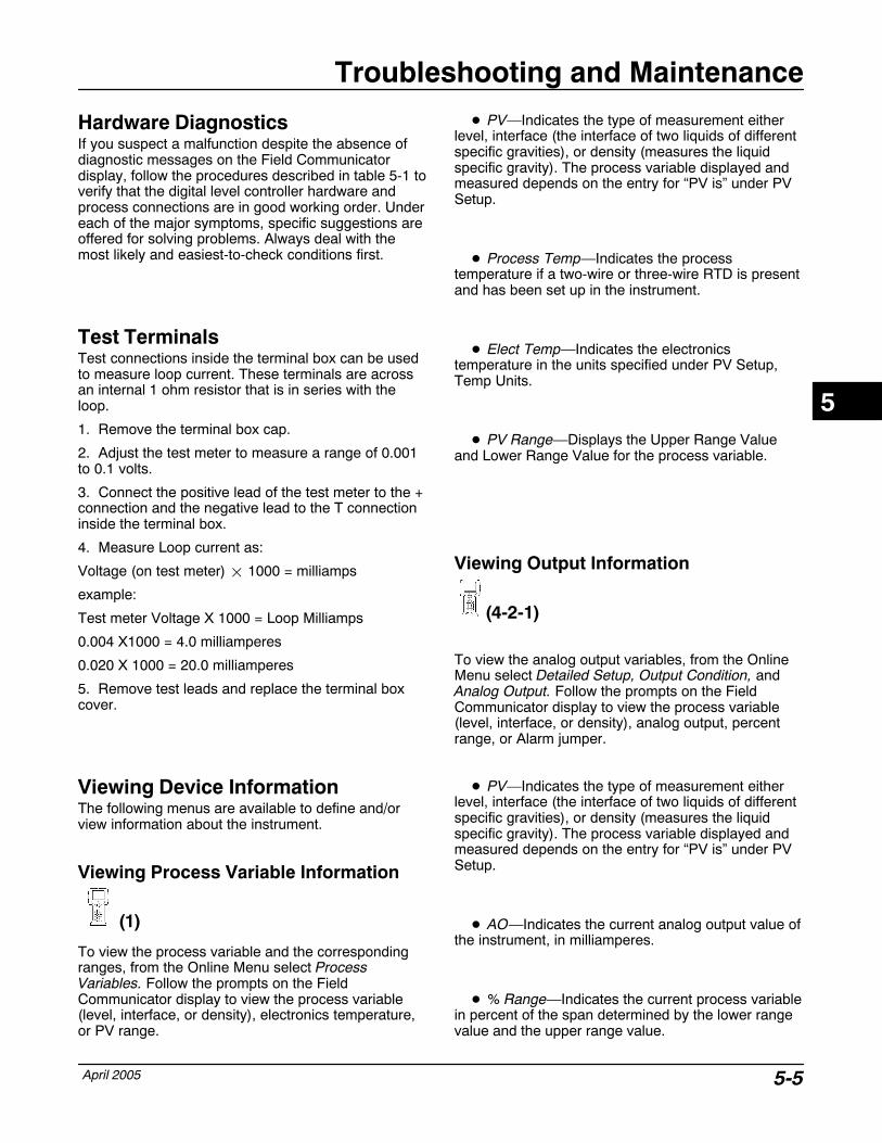
Troubleshooting and Maintenance
April 2005 5-5
Hardware Diagnostics If you suspect a malfunction despite the absence ofdiagnostic messages on the Field Communicatordisplay, follow the procedures described in table 5-1 toverify that the digital level controller hardware andprocess connections are in good working order. Undereach of the major symptoms, specific suggestions areoffered for solving problems. Always deal with themost likely and easiest-to-check conditions first.
Test Terminals Test connections inside the terminal box can be usedto measure loop current. These terminals are acrossan internal 1 ohm resistor that is in series with theloop.
1. Remove the terminal box cap.
2. Adjust the test meter to measure a range of 0.001to 0.1 volts.
3. Connect the positive lead of the test meter to the +connection and the negative lead to the T connectioninside the terminal box.
4. Measure Loop current as:
Voltage (on test meter) � 1000 = milliamps
example:
Test meter Voltage X 1000 = Loop Milliamps
0.004 X1000 = 4.0 milliamperes
0.020 X 1000 = 20.0 milliamperes
5. Remove test leads and replace the terminal boxcover.
Viewing Device InformationThe following menus are available to define and/orview information about the instrument.
Viewing Process Variable Information
(1)
To view the process variable and the correspondingranges, from the Online Menu select ProcessVariables. Follow the prompts on the FieldCommunicator display to view the process variable(level, interface, or density), electronics temperature,or PV range.
� PV—Indicates the type of measurement eitherlevel, interface (the interface of two liquids of differentspecific gravities), or density (measures the liquidspecific gravity). The process variable displayed andmeasured depends on the entry for “PV is” under PVSetup.
� Process Temp—Indicates the processtemperature if a two-wire or three-wire RTD is presentand has been set up in the instrument.
� Elect Temp—Indicates the electronicstemperature in the units specified under PV Setup,Temp Units.
� PV Range—Displays the Upper Range Valueand Lower Range Value for the process variable.
Viewing Output Information
(4-2-1)
To view the analog output variables, from the OnlineMenu select Detailed Setup, Output Condition, andAnalog Output. Follow the prompts on the FieldCommunicator display to view the process variable(level, interface, or density), analog output, percentrange, or Alarm jumper.
� PV—Indicates the type of measurement eitherlevel, interface (the interface of two liquids of differentspecific gravities), or density (measures the liquidspecific gravity). The process variable displayed andmeasured depends on the entry for “PV is” under PVSetup.
� AO—Indicates the current analog output value ofthe instrument, in milliamperes.
� % Range—Indicates the current process variablein percent of the span determined by the lower rangevalue and the upper range value.
5
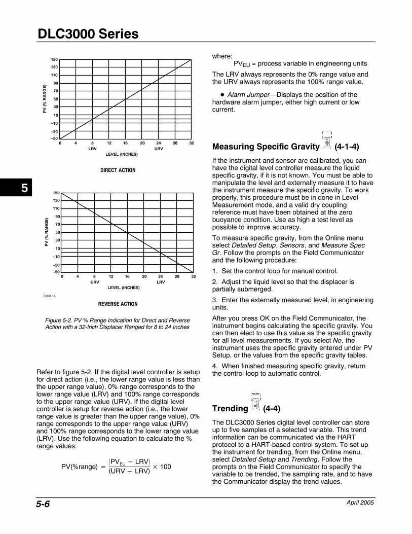
DLC3000 Series
April 20055-6
Figure 5-2. PV % Range Indication for Direct and ReverseAction with a 32-Inch Displacer Ranged for 8 to 24 Inches
DIRECT ACTION
REVERSE ACTION
150
130
110
90
70
50
30
10
–10
–30
–500 4 8 12 16 20 24 28 32
LRV URVLEVEL (INCHES)
PV
(%
RA
NG
E)
150
130
110
90
70
50
30
10
–10
–30
–500 4 8 12 16 20 24 28 32
LRVURVLEVEL (INCHES)
PV
(%
RA
NG
E)
E0383 / IL
Refer to figure 5-2. If the digital level controller is setupfor direct action (i.e., the lower range value is less thanthe upper range value), 0% range corresponds to thelower range value (LRV) and 100% range correspondsto the upper range value (URV). If the digital levelcontroller is setup for reverse action (i.e., the lowerrange value is greater than the upper range value), 0%range corresponds to the upper range value (URV)and 100% range corresponds to the lower range value(LRV). Use the following equation to calculate the %range values:
PV(%range) ��PVEU � LRV�
(URV � LRV)� 100
where: PVEU = process variable in engineering units
The LRV always represents the 0% range value andthe URV always represents the 100% range value.
� Alarm Jumper—Displays the position of thehardware alarm jumper, either high current or lowcurrent.
Measuring Specific Gravity (4-1-4)
If the instrument and sensor are calibrated, you canhave the digital level controller measure the liquidspecific gravity, if it is not known. You must be able tomanipulate the level and externally measure it to havethe instrument measure the specific gravity. To workproperly, this procedure must be in done in LevelMeasurement mode, and a valid dry couplingreference must have been obtained at the zerobuoyance condition. Use as high a test level aspossible to improve accuracy.
To measure specific gravity, from the Online menuselect Detailed Setup, Sensors, and Measure SpecGr. Follow the prompts on the Field Communicatorand the following procedure:
1. Set the control loop for manual control.
2. Adjust the liquid level so that the displacer ispartially submerged.
3. Enter the externally measured level, in engineeringunits.
After you press OK on the Field Communicator, theinstrument begins calculating the specific gravity. Youcan then elect to use this value as the specific gravityfor all level measurements. If you select No, theinstrument uses the specific gravity entered under PVSetup, or the values from the specific gravity tables.
4. When finished measuring specific gravity, returnthe control loop to automatic control.
Trending (4-4)
The DLC3000 Series digital level controller can storeup to five samples of a selected variable. This trendinformation can be communicated via the HARTprotocol to a HART-based control system. To set upthe instrument for trending, from the Online menu,select Detailed Setup and Trending. Follow theprompts on the Field Communicator to specify thevariable to be trended, the sampling rate, and to havethe Communicator display the trend values.
5
Troubleshooting and Maintenance
April 2005 5-7
� Trend Var—Permits selecting the variable fortrending: PV, Process Temperature, or ElectronicsTemperature. Off turns the trending function off.
� Trend Interval—Permits selecting how often theinstrument should sample and store the selected trendvariable. Enter a sample interval between 0.2 and 10.0seconds.
� Read Trend—Permits viewing the five mostrecent samples on the Field Communicator display.The five sample values are displayed along with asample number. The smaller sample number containsthe oldest sample value. When finished viewing thedisplayed sample values, press OK on the FieldCommunicator to view the next five samples. PressABORT to exit the display.
Viewing the Device ID (4-3-4)
Each instrument has a unique Device Identifier. Thedevice ID provides additional security to prevent thisinstrument from accepting commands meant for otherinstruments. To view the device ID, from the OnlineMenu select Detailed Setup, Device Information, andDevice ID.
Viewing Version Information (4-3-2)
The Version Information menu is available to viewinformation about the instrument. From the Onlinemenu, select Detailed Setup, Device Information, andVersion Info. Follow the prompts on the FieldCommunicator display to view information in thefollowing fields: Device Rev (Device Revision),Firmware Rev (Firmware Revision), Hardware Rev(Hardware Revision), HART Univ Rev (HARTUniversal Revision).
� Device Rev—Device Revision is the revision ofthe protocol for interfacing to the functionality of theinstrument.
� Firmware Rev—Firmware Revision is the revisionnumber of the Fisher software in the instrument.
� Hardware Rev—Hardware Revision is therevision number of the Fisher instrument hardware.
� HART Univ Rev—HART Universal Revision isthe revision number of the HART Universal
Commands which are used as the communicationsprotocol for the instrument.
� 375 DD Rev—DD Rev is the revision level of theDevice Description used by the 375 FieldCommunicator while communicating with theinstrument.
Viewing Serial Number Information
(4-3-3)
To view or enter serial number information, from theOnline menu select Detailed Setup, DeviceInformation, and Serial Numbers. Follow the promptson the Field Communicator display to enter or view thefollowing serial numbers: Instrument S/N (InstrumentSerial Number), Displacer S/N (Displacer SerialNumber), and Final Assembly Num (Final AssemblyNumber).
� Instrument S/N—Enter the serial number on theinstrument nameplate, up to 12 characters.
� Displacer S/N—Use this field to enter or view thedisplacer serial number. The displacer serial number isthe same as the sensor serial number found on thesensor nameplate.
� Final Assembly Num—The Final AssemblyNumber is a number that can be used to identify theinstrument and sensor combination.
Viewing Process and TemperatureAlarms
(4-2-4)
To view active process or temperature alarms, fromthe Online menu, select Detailed Setup, OutputCondition, and Display Alarms.
If a process or temperature alarm is active, it willappear when the Display Alarms menu is selected. Ifmore than one alarm is active, they will appear on thedisplay one at a time in the order listed below.
1. PV Exceeds Hi Alarm Limit
2. PV Exceeds Hi Hi Alarm Limit
3. PV Exceeds Lo Alarm Limit
4. PV Exceeds Lo Lo Alarm Limit
5. Process Temperature Exceeds Hi Alarm Limit
6. Process Temperature Exceeds Lo Alarm Limit
5
DLC3000 Series
April 20055-8
7. Electronics Temperature Exceeds Hi Alarm Limit
8. Electronics Temperature Exceeds Lo Alarm Limit
Viewing Hardware Alarms (2-3)
To view hardware alarm information, from the Onlinemenu select Diag/Service and Hardware Alarms.Follow the prompts on the Field Communicator displayto view information in the following fields: AlarmJumper, NVM (Non-Volatile Memory), Free Time,Level Snsr Drive (Level Sensor Drive), and A/D TTInput (Analog to Digital Torque Tube Input).
� Alarm Jumper—Displays the position of thehardware alarm jumper, either high current or lowcurrent.
� NVM—Displays the current value of theremaining number of NVM writes. Setup data is storedin NVM. If the remaining number of NVM writes seemsto be decreasing rapidly, check to make sure thecontrol system is not unnecessarily writing to theNVM. Reaching 0 will cause the NVM Write LimitExceeded status to be activated.
� Free Time—Displays the current microprocessorfree time. If the free time limit check fails, the FreeTime Limit Exceeded status is activated.
� Level Snsr Drive—Displays the current limit andvalue of the Level Sensor Drive Signal. If the drivevalue exceeds the hardcoded limits, either above orbelow, the instrument forces the output current to thealarm value determined by the alarm jumper andactivates the Field Device Malfunction statusmessage. (The Level Snsr Drive Limit field is forfactory use only.)
� A/D TT Input—Displays the current limit andvalue of the A/D Torque Tube Input. If the inputexceeds the hardcoded limits, either above or below,the Torque Tube A/D Input Failed status is activated.(The A/D TT Input Limit field is for factory use only.)
Viewing Instrument Status (2-1-1) To view the instrument status, from the Online menuselect Diag/Service, Test Device, Status. Thefollowing describes the various displays for theinstrument Status menu.
� Torque Tube A/D Input Failed—When active,indicates the torque tube position reading hasexceeded the hardcoded limits, either above or below.When active the instrument forces the output currentto the alarm value determined by the alarm jumper. Ifthis status message appears, the lever assembly maybeen driven to a hard stop by a bad mechanicalcoupling condition. Try recoupling the instrument toclear it. If it does not clear, from the Online menu,select Diag/Serv, Hardware Alarms, A/D TT input(2-3-5). If the value is 1230 mV and does not respondto lever assembly motion, try installing a newElectronics Module. If a new Electronics Module doesnot clear the failure, the Transducer Module is at fault.
NoteWhen using the handheldcommunicator, it is necessary to exitthe menu item, move the lever, andre-enter the menu item with the lever inthe new position. The variable is notread dynamically, only once per entry.In AMS Device Manager, this variableis updated dynamically, although at aslow rate.
� Hall Current Readback Limit Failed—Whenactive, indicates the Hall current readback hasexceeded the hardcoded limits, either above or below.When active the instrument forces the output currentto the alarm value determined by the alarm jumper.This status typically indicates an electronics failure. Ifthis status message appears, try cycling power to theinstrument and see if it clears. If it does not clear, tryreplacing the Electronics Module. If the message stilldoesn’t clear, the problem is on the transducer board.Contact your Fisher sales office for repair information.
� Reference Voltage Limit Failed—When active,indicates the reference voltage reading of the A/Dconverter has exceeded the hardcoded limits, eitherabove or below. When active the instrument forces theoutput current to the alarm value determined by thealarm jumper. If this status message appears, trycycling power to the instrument and see if it clears. If itdoes not clear, replace the Electronics Module.
5
Troubleshooting and Maintenance
April 2005 5-9
� NVM Write Limit Exceeded—When active,indicates the total number of writes to one of the threeareas of NVM has exceeded the hardcoded limit. Ifthis status message appears, run the hardware alarmdiagnostics to determine which area of NVM is at zerocount. From the Online menu, select Diag/Serv,Hardware Alarms, NVM (2-3-2).
If the HC12 (Microprocessor) count is zero, correct thecondition that is causing excessive writes to thetransmitter. Try cycling power to the instrument andsee if it clears. If it does not clear, replace theElectronics Module. If the Hall (Transducer) count iszero, replace the Transducer Module.
� Free Time Limit Exceeded—When active,indicates the instrument has failed the free time checkand the execution period cannot be maintained. If thisstatus message appears, try cycling power to theinstrument and see if it clears. If it does not clear,replace the Electronics Module.
� Process Temperature Sensor Failed—Whenactive, indicates the process temperature sensor(RTD) reading has exceeded the hardcoded limits(<10 ohms or >320 ohms). If this status messageappears, reinstall the process temperature sensor(RTD).
The following status messages appear whenever theyare active. You do not need to access any specificOnline menu item to see them.
� Field Device Malfunction—When active,indicates that an attempt to write to NVM failed,usually in the message or date fields. Try to write thefield again at a later time.
� Primary Variable Analog Output Fixed—Whenactive, indicates the analog and digital outputs for thePrimary Variable are held at the requested value. Theywill not respond to the applied process.
� Primary Variable Analog Output Saturated—When active, indicates the analog and digital outputsfor the Primary Variable are beyond their limits and nolonger represent the true applied process.
� Non-Primary Variable Out of Limits—Whenactive, indicates the process applied to a sensor, otherthan that of the Primary Variable, is beyond theoperating limits of the device. This indicates atemperature alarm is active.
� Primary Variable Out of Limits—When active,indicates the process applied to the sensor for thePrimary Variable is beyond the operating limits of thedevice.
Removing the Digital LevelController from the Sensor Because of its modular design, most of the serviceand maintenance to the digital level controller can bedone without removing it from the sensor. However, ifnecessary to replace sensor to instrument matingparts or parts in the transducer housing, or to performbench maintenance, perform the following proceduresto remove the digital level controller from the sensor.
WARNING
On an explosion-proof instrument,remove the electrical power beforeremoving the instrument covers in ahazardous area. Personal injury orproperty damage may result from fireand explosion if power is applied tothe instrument with the coversremoved.
Tools Required
Table 5-2 lists the tools required for maintaining theDLC3000 Series digital level controller.
Removing the Type DLC3010 DigitalLevel Controller from a 249 SeriesSensor
249 Series Sensor in StandardTemperature Applications
1. Loosen the set screw (key 31) in the terminal boxcover assembly (key 6) so that the cover can beunscrewed from the terminal box.
2. After removing the cover (key 6), note the locationof field wiring connections and disconnect the fieldwiring from the wiring terminals.
3. As shown in figure 3-5, locate the access handleon the bottom of the transducer housing. Using a 2mm hex key, back out the set screw in the depressionon the access handle until it is flush with the handlesurface. Press on the back of the handle, as shown inthe figure, and slide the handle toward the front of theunit, (the locked position), to expose the access hole.Be sure the locking handle drops into the detent.
5
DLC3000 Series
April 20055-10
Table 5-2. Tools RequiredTool Size Usage Keys
Hex Key 2 mm HandleCover-lock set screws
3120
Hex Key 2.5 mm Small cap screws 13
Hex Key 4 mm Lever assembly mtg capscrew
14
Hex Key 5 mm Terminal box mtg cap screw 7
Hex Socket 10 mm Coupling nut 76
Open-end 13 mm Transmitter mounting nuts 34
PhillipsScrewdriver
Terminal screwsElectronics module mtgscrews
2536
Small flat bladescrewdriver
LCD assy mtg screws 40
Strap wrenchHelpful for removing a displaycover that has beenover-tightened
3
Large flat bladescrewdriver(1) Flex circuit mtg screws 19
Needle nosepliers(1) Align/clamp ring extraction 17
1. Needed to remove a flex circuit if date code numbers are requested for warrantyinformation.
NoteIf the access handle will not slide, thesensor linkage is most likely in anextreme position. When the leverassembly is at a hard stop inside thehousing, the locking pin on the accessdoor may not be able to engage themating slot in the lever assembly. Thiscondition can occur if the displacerhas been removed, if the sensor islying on its side, or if the instrumenthad been coupled to the sensor whilethe displacer was not connected. Tocorrect this condition, manipulate thesensor linkage to bring the leverassembly to within approximately 4degrees of the neutral position beforeattempting to slide the handle. A probeinserted through the top vent of the249 head may be required to deflectthe driver rod to a position where thelever assembly is free.
4. Using a 10 mm deep well socket inserted throughthe access hole, loosen the shaft clamp (figure 3-5).
5. Loosen and remove the hex nuts (key 34) from themounting studs (key 33).
6. Carefully pull the digital level controller straight offthe sensor torque tube.
CAUTION
Tilting the instrument when pulling itoff of the sensor torque tube cancause the torque tube shaft to bend.To prevent damage to the torque tubeshaft, ensure that the digital levelcontroller is level when pulling it off ofthe sensor torque tube.
7. When re-installing the digital level controller, followthe appropriate procedure outlined in the Installationsection. Also setup the digital level controller asdescribed in the Initial Setup section.
249 Series Sensor in High TemperatureApplication
1. Loosen the set screw (key 31) in the terminal boxcover assembly (key 6) so that the cover can beunscrewed from the terminal box.
2. After removing the cover (key 6), note the locationof field wiring connections and disconnect the fieldwiring from the wiring terminals.
3. As shown in figure 3-5, locate the access handleon the bottom of the transducer housing. Using a 2mm hex key, back out the set screw in the depressionon the access handle until it is flush with the handlesurface. Press on the back of the handle, as shown inthe figure, and slide the handle toward the front of theunit, (the locked position), to expose the access hole.Be sure the locking handle drops into the detent.
5
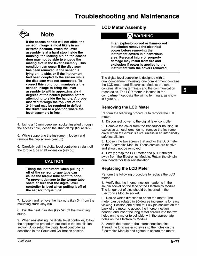
Troubleshooting and Maintenance
April 2005 5-11
NoteIf the access handle will not slide, thesensor linkage is most likely in anextreme position. When the leverassembly is at a hard stop inside thehousing, the locking pin on the accessdoor may not be able to engage themating slot in the lever assembly. Thiscondition can occur if the displacerhas been removed, if the sensor islying on its side, or if the instrumenthad been coupled to the sensor whilethe displacer was not connected. Tocorrect this condition, manipulate thesensor linkage to bring the leverassembly to within approximately 4degrees of the neutral position beforeattempting to slide the handle. A probeinserted through the top vent of the249 head may be required to deflectthe driver rod to a position where thelever assembly is free.
4. Using a 10 mm deep well socket inserted throughthe access hole, loosen the shaft clamp (figure 3-5).
5. While supporting the instrument, loosen andremove the cap screws (key 63).
6. Carefully pull the digital level controller straight offthe torque tube shaft extension (key 58).
CAUTION
Tilting the instrument when pulling itoff of the sensor torque tube cancause the torque tube shaft to bend.To prevent damage to the torque tubeshaft, ensure that the digital levelcontroller is level when pulling it off ofthe sensor torque tube.
7. Loosen and remove the hex nuts (key 34) from themounting studs (key 33).
8. Pull the heat insulator (key 57) off the mountingstuds.
9. When re-installing the digital level controller, followthe appropriate procedure outlined in the Installationsection. Also setup the digital level controller asdescribed in the Setup and Calibration section.
LCD Meter Assembly
WARNING
In an explosion-proof or flame-proofinstallation remove the electricalpower before removing theinstrument covers in a hazardousarea. Personal injury or propertydamage may result from fire andexplosion if power is applied to theinstrument with the covers removed.
The digital level controller is designed with adual-compartment housing; one compartment containsthe LCD meter and Electronics Module; the othercontains all wiring terminals and the communicationreceptacles. The LCD meter is located in thecompartment opposite the wiring terminals, as shownin figure 5-3.
Removing the LCD Meter Perform the following procedure to remove the LCDmeter.1. Disconnect power to the digital level controller.2. Remove the cover from the transducer housing. Inexplosive atmospheres, do not remove the instrumentcover when the circuit is alive, unless in an intrinsicallysafe installation.3. Loosen the two screws that anchor the LCD meterto the Electronics Module. These screws are captiveand should not be removed.4. Firmly grasp the LCD meter and pull it straightaway from the Electronics Module. Retain the six-pindual header for later reinstallation.
Replacing the LCD Meter Perform the following procedure to replace the LCDmeter.1. Verify that the interconnection header is in thesix-pin socket on the face of the Electronics Module.The longer set of pins should be inserted in theElectronics Module socket.2. Decide which direction to orient the meter. Themeter can be rotated in 90-degree increments for easyviewing. Position one of the four six-pin sockets on theback of the meter to accept the interconnectionheader, and insert the long meter screws into the twoholes on the meter to coincide with the appropriateholes on the Electronics Module.3. Attach the meter to the interconnection pins.Thread the long meter screws into the holes on theElectronics Module and tighten to secure the meter.
5
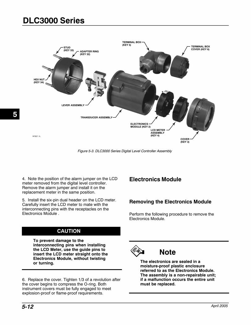
DLC3000 Series
April 20055-12
Figure 5-3. DLC3000 Series Digital Level Controller Assembly
COVER(KEY 3)
LCD METERASSEMBLY(KEY 4)
ELECTRONICSMODULE (KEY 2)
TRANSDUCER ASSEMBLY
TERMINAL BOX(KEY 5)
TERMINAL BOX COVER (KEY 6)
LEVER ASSEMBLY
ADAPTER RING(KEY 32)
W7927 / IL
STUD(KEY 33)
HEX NUT(KEY 34)
4. Note the position of the alarm jumper on the LCDmeter removed from the digital level controller.Remove the alarm jumper and install it on thereplacement meter in the same position.
5. Install the six-pin dual header on the LCD meter.Carefully insert the LCD meter to mate with theinterconnecting pins with the receptacles on theElectronics Module .
CAUTION
To prevent damage to theinterconnecting pins when installingthe LCD Meter, use the guide pins toinsert the LCD meter straight onto theElectronics Module, without twistingor turning.
6. Replace the cover. Tighten 1/3 of a revolution afterthe cover begins to compress the O-ring. Bothinstrument covers must be fully engaged to meetexplosion-proof or flame-proof requirements.
Electronics Module
Removing the Electronics Module
Perform the following procedure to remove theElectronics Module.
NoteThe electronics are sealed in amoisture-proof plastic enclosurereferred to as the Electronics Module.The assembly is a non-repairable unit;if a malfunction occurs the entire unitmust be replaced.
5
Troubleshooting and Maintenance
April 2005 5-13
WARNING
On an explosion-proof instrument,remove the electrical power beforeremoving the instrument covers in ahazardous area. Personal injury orproperty damage may result from fireand explosion if power is applied tothe instrument with the coversremoved.
1. Disconnect power to the digital level controller.
2. Remove the cover from the transducer housing. Inexplosive atmospheres, do not remove the instrumentcover when the circuit is alive, unless in an intrinsicallysafe installation. Remove the LCD meter assembly.
3. Loosen the two screws that anchor the ElectronicsModule to the transducer housing. These screws arecaptive and should not be removed.
4. Firmly grasp the Electronics Module and pull itstraight out of the housing.
Replacing the Electronics Module
Perform the following procedure to replace theElectronics Module.
1. Carefully insert the Electronics Module to mate theinterconnecting pins with the receptacles on theTransducer housing.
CAUTION
To prevent damage to theinterconnecting pins when installingthe Electronics Module, use the guidepins to insert the Electronics Modulestraight onto the Transducer housingreceptacles without twisting orturning.
2. Tighten the two mounting screws. Replace the LCDmeter assembly.
3. Replace the cover. Tighten 1/3 of a revolution afterthe cover begins to compress the O-ring. Bothinstrument covers must be fully engaged to meetexplosion-proof requirements.
Terminal BoxThe terminal box is located on the transducer housingand contains the terminal strip assembly for fieldwiring connections. Unless indicated otherwise, referto figure 6-3.
WARNING
On an explosion-proof instrument,remove the electrical power beforeremoving the instrument covers in ahazardous area. Personal injury orproperty damage may result from fireand explosion if power is applied tothe instrument with the coversremoved.
Removing the Terminal Box
1. Loosen the set screw (key 31) in the terminal boxcover assembly (key 6) so that the cover can beunscrewed from the terminal box.
2. After removing the cover (key 6), note the locationof field wiring connections and disconnect the fieldwiring from the wiring terminals.
3. Remove the screw (key 7), and pull out theterminal box assembly.
CAUTION
To avoid damaging the terminal boxassembly connector, pull the terminalbox assembly straight out of thehousing, without twisting or turning.
5

DLC3000 Series
April 20055-14
Replacing the Terminal Box
NoteInspect all O-rings for wear and replace asnecessary.
1. Apply sealant to the O-ring (key 27) and install theO-ring over the stem of the terminal box as shown infigure 6-3.
2. Orient the terminal box so that the connectorsengage properly, and carefully insert the terminal boxinto the transducer housing until the O-ring is seated.
CAUTION
To avoid damaging the mating pins inthe Transducer housing, ensure thatthe guiding mechanism is engagedproperly before applying force.
3. Fasten the terminal box to the transducer housingwith the screw (key 7). Tighten the screw to 6 N�m (53lbf�in).
4. Apply sealant to the O-ring (key 26) and install theO-ring over the cover threads on the terminal box. Usea tool to prevent cutting the O-ring while installing itover the threads.
5. Reconnect the field wiring as noted in step 2 in theRemoving the Terminal Box procedure.
6. Apply lubricant to the threads on the terminal boxto prevent seizing or galling while installing theterminal box cover.
7. Screw the terminal box cover assembly (key 6)completely onto the terminal box to seat the O-ring(key 26). Loosen the cover (not more than 1 turn) untilthe set screw (key 31) aligns with one of the recessesin the terminal box beneath the cover. Tighten the setscrew to engage the recesses but no more than 0.88N�m (7.8 lbf�in).
8. Apply lubricant to the conduit entrance plug (key 28) and install it in the unused conduit entrance.
Figure 5-4. Installing Inner Guide and Access Handle Assembly
ZERO LOCKING PININNER GUIDE(KEY 11)
VENT HOLE
LUBRICATETHIS SURFACE
VENT HOLES
HANDLEASSEMBLY(KEY 12)
SCREWS (KEY 13)
LUBRICATETHIS SURFACE
TRANSDUCER HOUSING
ACCESS HOLEE0381 / IL
Removing and Replacing the InnerGuide and Access Handle AssemblyThe access handle and inner guide are located on thetransducer housing. Unless indicated otherwise, referto figure 6-2.
1. Remove the digital level controller from the sensoras described in Removing the Digital Level Controllerfrom the Sensor.
2. Loosen and remove the hex nuts (key 34) from thestuds (key 33) and remove the adapter ring (key 32).
NoteIn the next step the screws (key 13)will be attracted by the magnets on thelever assembly. Use care to keep thescrews from falling beneath thecoupling shield.
5
Troubleshooting and Maintenance
April 2005 5-15
3. Remove the coupling shield (key 16) by removingthe two screws (key 13). Take care not to drop thescrews into the lever assembly compartment wherethey will be attracted by the magnets.
4. Loosen and remove the two screws (key 13) in thehandle assembly (key 12). Remove the handleassembly and the inner guide (key 11).
5. Apply thread lock to the internal threads of thereplacement inner guide. Also apply a thin coat of alight grade of grease to the zero locking pin on theinner guide and on the surface that is opposite thezero locking pin, as shown in figure 5-4 (this surfacecontacts the transducer housing when installed).
6. Place the inner guide in the slot inside thetransducer housing so that the vent holes in the innerguide (the milled slots in the inner guide, see figure5-4) face the exterior of the housing and are over theaccess hole.
7. Apply a thin coat of a light grade of grease to thesurface of the replacement handle assembly (seefigure 5-4) where it will contact the transducer housing.
8. Install the handle assembly (key 12) in the slot ofthe transducer housing over the inner guide (key 11)so that the vent holes in the handle assembly are overthe access hole.
9. Install two screws (key 13) to secure the handleassembly (key 12) to the inner guide (key 11). Tightenthe screws to 0.48 N�m (4.2 lbf�in).
10. Press down on the handle as shown in figure 3-5and slide it forward to make sure it works smoothlyand that the zero locking pin engages the leverassembly. Also check for free travel of the leverassembly when the handle is in the unlocked position.
11. Install the coupling shield (key 16) and securewith the two screws (key 13). Tighten the screws to0.48 N�m (4.2 lbf�in).
12. Refer to figure 6-1. Install the adapter ring (key32) on the studs (key 33) and secure with hex nuts(key 34).
13. When re-installing the digital level controller,follow the appropriate procedure outlined in theInstallation section. Also setup the digital levelcontroller as described in the Setup and Calibrationsection.
Lever Assembly
Removing the Lever AssemblyThe lever assembly is located in the transducerhousing. Unless indicated otherwise, refer to figure6-2.1. Remove the digital level controller from the sensoras described in Removing the Digital Level Controllerfrom the Sensor.2. Loosen and remove the hex nuts (key 34) from thestuds (key 33) and remove the adapter ring (key 32).3. Remove the coupling shield (key 16) by removingthe two screws (key 13). Take care not to drop thescrews into the lever assembly compartment wherethey will be attracted by the magnets.4. Inspect the lever assembly alignment with thehousing. If it is off center or not co-axial with the mainhousing, continue with the removal procedure.5. Loosen and remove the mounting screw (key 14)from the lever assembly.6. Loosen the flexure block from its machined pocketin the housing, by inserting a smooth tool into the holefor the mounting screw, and gently rocking it back andforth in what would be the vertical axis if thetransmitter were installed.7. Lift the lever assembly out of the housing.Inspect the flexure for damage. If the flexure is bent ortorn, replace the lever assembly.
Replacing the Lever AssemblyReplacing the lever assembly in the field may result ina slight degradation in linearity performance, since thefactory characterizes the entire transducer module asa unit. For most applications, this degradation shouldnot be noticeable. (If guaranteed restoration to factoryspecification is desired, the entire transducer moduleshould be replaced.)1. Move the zero-pin slide to the locking position.2. Apply a thin coat of a light grade of grease to theinternal thread of the hole for the lever mounting bolt.3. Hold lever assembly by coupling block and guidethe flexure block into its aligning slot in the housingwithout applying any downward force to the sprungparts of the lever assembly.
CAUTION
To prevent damage to the flexure wheninserting the flexure block into itsaligning slot in the housing, applypressure to the flexure block only.
5
DLC3000 Series
April 20055-16
A long pin inserted into the bolt-hole in the flexureblock may be used to pull it against the inside cornerof the aligning slot.
4. Secure the block by reinstalling the M5x20socket-head cap screw (key 14). Torque to 2.8 N�m(25 lbf�in) �10%.
5. Mark bolt head and block with amovement-detecting sealant.
6. Install the coupling shield (key 16) and secure withthe two screws (key 13). Tighten the screws to 0.48N�m (4.2 lbf�in).
7. Refer to figure 6-1. Install the adapter ring (key 32)on the studs (key 33) and secure with hex nuts (key34). When re-installing the digital level controller,follow the appropriate procedure outlined in theInstallation section. Set up the digital level controlleras described in the Setup and Calibration section.
Packing for Shipment
If it becomes necessary to return the unit for repair ordiagnosis, contact your Fisher sales office for returnedgoods information.
CAUTION
Lock the lever assembly whenshipping the stand-alone instrument,to prevent damage to the flexure.
Use the original shipping carton ifpossible.
5
Replaceable Parts
April 2005 6-1
6-6
Section 6 Replaceable Parts
Parts Ordering 6-2. . . . . . . . . . . . . . . . . . . . . . . . . . . . . . . . . . . . . . . . . . . . . . . . . . . . . . . . . . .
Mounting Kits 6-2. . . . . . . . . . . . . . . . . . . . . . . . . . . . . . . . . . . . . . . . . . . . . . . . . . . . . . . . . . .
Repair Kits 6-2. . . . . . . . . . . . . . . . . . . . . . . . . . . . . . . . . . . . . . . . . . . . . . . . . . . . . . . . . . . . . . .
Parts List 6-3. . . . . . . . . . . . . . . . . . . . . . . . . . . . . . . . . . . . . . . . . . . . . . . . . . . . . . . . . . . . . . . .
Type DLC3010 Digital Level Controllers 6-3. . . . . . . . . . . . . . . . . . . . . . . . . . . . . . . . . .
Transducer Assembly 6-4. . . . . . . . . . . . . . . . . . . . . . . . . . . . . . . . . . . . . . . . . . . . . . .
Terminal Box Assembly 6-5. . . . . . . . . . . . . . . . . . . . . . . . . . . . . . . . . . . . . . . . . . . . .
Terminal Box Cover Assembly 6-5. . . . . . . . . . . . . . . . . . . . . . . . . . . . . . . . . . . . . . .
Mounting Parts 6-6. . . . . . . . . . . . . . . . . . . . . . . . . . . . . . . . . . . . . . . . . . . . . . . . . . . . . . . . . . 249 Series Sensor with Heat Insulator 6-6. . . . . . . . . . . . . . . . . . . . . . . . . . . . . . . . . . . . . .
6
DLC3000 Series
April 20056-2
Table 6-1. Mounting Kits
Fisher 249 MasoneilanYamatake NQP
Foxboro-EckardtFisher 249Series 12100 or 12800 12200 or 12300
Yamatake NQP144LD LP167
Without Heat Insulator - - - 28B5742X012 28B8444X012 GB0101X0012 29B5900X012 29B8480X012
With Heat Insulator 28B5741X012 28B5743X012 28B8445X012 GB0105X0012 29B8491X012 - - -
Parts Ordering Whenever corresponding with your Fisher sales officeabout this equipment, always mention the controllerserial number. When ordering replacement parts, referto the 11-character part number of each required partas found in the following parts list. Parts that do notshow part numbers are not orderable.
NoteUse only genuine Fisher replacementparts. Components that are notsupplied by Fisher should not, underany circumstances, be used in anyFisher instrument. The use ofcomponents not manufactured byFisher will void your warranty, mightadversely affect the performance of theinstrument, and might jeopardizeworker and workplace safety.
NoteNeither Emerson, Emerson ProcessManagement, nor Fisher assumeresponsibility for the selection, use, ormaintenance of any product.Responsibility for the selection, use,and maintenance of any Fisherproduct remains solely with thepurchaser and end-user.
Mounting Kits
Heat Insulator Kit, for mounting Type DLC3010 on249 Series sensor. Includes heat insulator(key 57), cap screws (key 61), shaft extension(key 58), shaft coupling (key 59), andset screws (key 60). 28B5741X012
NoteContact your Fisher sales office forinformation on the availability ofadditional mounting kits.
Parts Kits 1* Small Hardware Spare Parts Kit 19B1643X032
Description Qty/kitIncludes
Screw (key 7) 1Set Screw (key 20) 2Set Screw (key 31) 2Test Terminal (key 24 4Wire Retainer (key 25) 8Lock Washer (key 31) 1Alarm Jumper (key 35) 2Header Assembly (key 38) 2Clamp Nut (key 76) 1
2* Spare O-Rings Kit 19B1643X022Includes three each of keys 21, 26, and 27
6
* Recommended spare part

Replaceable Parts
April 2005 6-3
NOTES:INSTALL ALARM JUMPER (KEY 35) ON ELECTRONICS ASSEMBLY (KEY2) WHEN LCD METER (KEY 4) IS NOT INSTALLED.LOCATION OF ALARM JUMPER (KEY 35) WHEN LCD METER (KEY 4) IS INSTALLED.
Figure 6-1. DLC3000 Series Digital Level Controller Assembly
1
2
12
58B5510-AE0382 / IL
APPLY LUB/THREADLOCK
21
Parts List
Type DLC3010 Digital Level Controllers(figure 6-1) Key Description Part Number2 Electronics Ass’y, includes alarm jumper
(key 35) and captive screws (key 36) 18B5529X0123 Cover, includes O-ring (key 21) 38B5734X0124 LCD Meter Ass’y, includes header ass’y
(key 38) and captive screws (key 40) 38B5738X0125 Terminal Box Ass’y 28B5740X0226 Terminal Box Cover Ass’y, includes labels
(key 30 and 64) and set screw (key 31) 28B5531X0127* Screw, hex socket(1) 11B9076X0428 Nameplate
Key Description Part Number9 Drive Screw, 18-8 sst 1A368228982
21* O-ring, nitrile(2) 1K1810X001232 Adaptor Ring, A03600 1N10160G01233 Stud, sst (4 req’d) 1N10162G01234 Hex Nut, 304 sst (4 req’d) 1N10252G01235* Alarm Jumper(1) 18B5733X01236 Screw, captive, 18-8 sst
For electronics ass’y (2 req’d) 18B5732X02238* Header Assembly, dual row (not shown)(1) 18B5736X01240 Screw, captive, 18-8 sst
For LCD meter (2 req’d) 18B5732X01266 Zink-Plate No. 770 Anti-Seize Compound
(not furnished with instrument)67 Thread Lock, Loctite 242
(not furnished with instrument)
6
* Recommended spare part1. Included in small hardware spare parts kit.2. Included in spare O-rings kit.
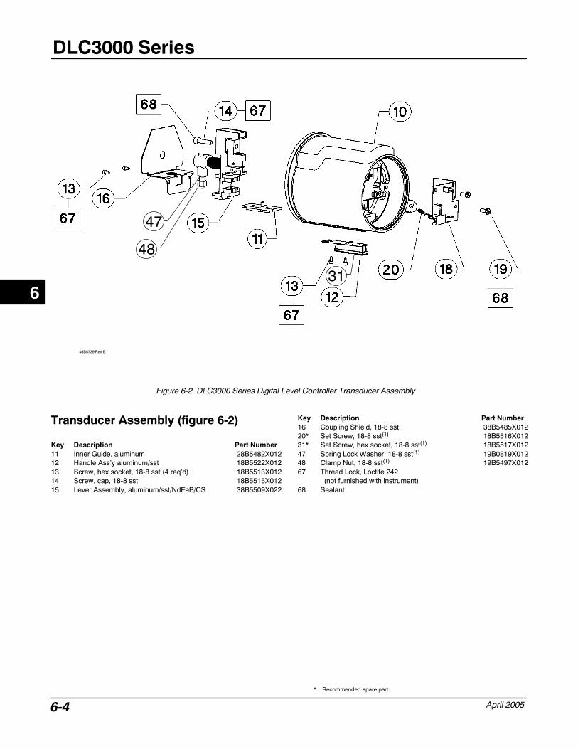
DLC3000 Series
April 20056-4
Figure 6-2. DLC3000 Series Digital Level Controller Transducer Assembly
48B5739 Rev B
31
47
48
Transducer Assembly (figure 6-2)
Key Description Part Number11 Inner Guide, aluminum 28B5482X01212 Handle Ass’y aluminum/sst 18B5522X01213 Screw, hex socket, 18-8 sst (4 req’d) 18B5513X01214 Screw, cap, 18-8 sst 18B5515X01215 Lever Assembly, aluminum/sst/NdFeB/CS 38B5509X022
Key Description Part Number16 Coupling Shield, 18-8 sst 38B5485X01220* Set Screw, 18-8 sst(1) 18B5516X01231* Set Screw, hex socket, 18-8 sst(1) 18B5517X01247 Spring Lock Washer, 18-8 sst(1) 19B0819X01248 Clamp Nut, 18-8 sst(1) 19B5497X01267 Thread Lock, Loctite 242
(not furnished with instrument)68 Sealant
6
* Recommended spare part
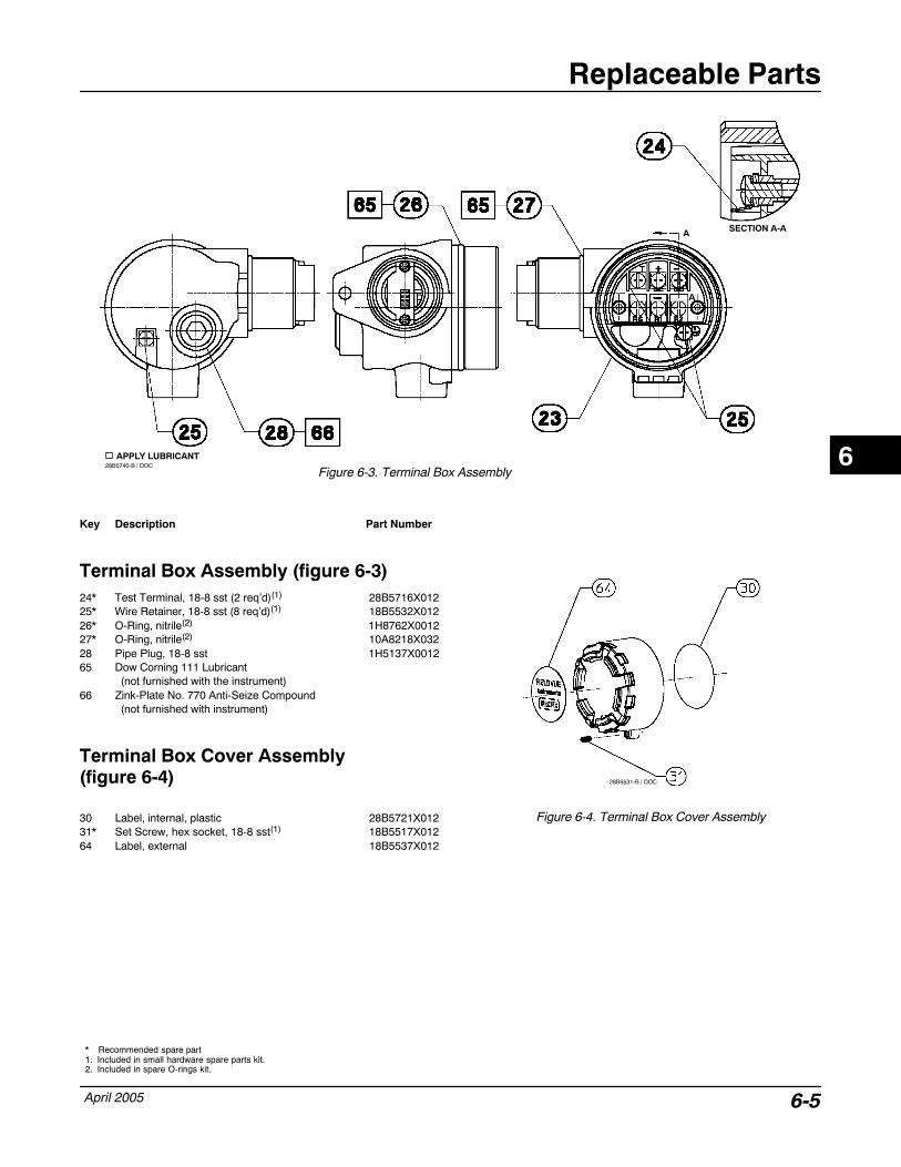
Replaceable Parts
April 2005 6-5
Figure 6-3. Terminal Box Assembly28B5740-B / DOC APPLY LUBRICANT
SECTION A-AA
A
Key Description Part Number
Terminal Box Assembly (figure 6-3)24* Test Terminal, 18-8 sst (2 req’d)(1) 28B5716X01225* Wire Retainer, 18-8 sst (8 req’d)(1) 18B5532X01226* O-Ring, nitrile(2) 1H8762X001227* O-Ring, nitrile(2) 10A8218X03228 Pipe Plug, 18-8 sst 1H5137X001265 Dow Corning 111 Lubricant
(not furnished with the instrument)66 Zink-Plate No. 770 Anti-Seize Compound
(not furnished with instrument)
Terminal Box Cover Assembly(figure 6-4)
30 Label, internal, plastic 28B5721X01231* Set Screw, hex socket, 18-8 sst(1) 18B5517X01264 Label, external 18B5537X012
Figure 6-4. Terminal Box Cover Assembly
28B5531-B / DOC
6
* Recommended spare part1. Included in small hardware spare parts kit.2. Included in spare O-rings kit.
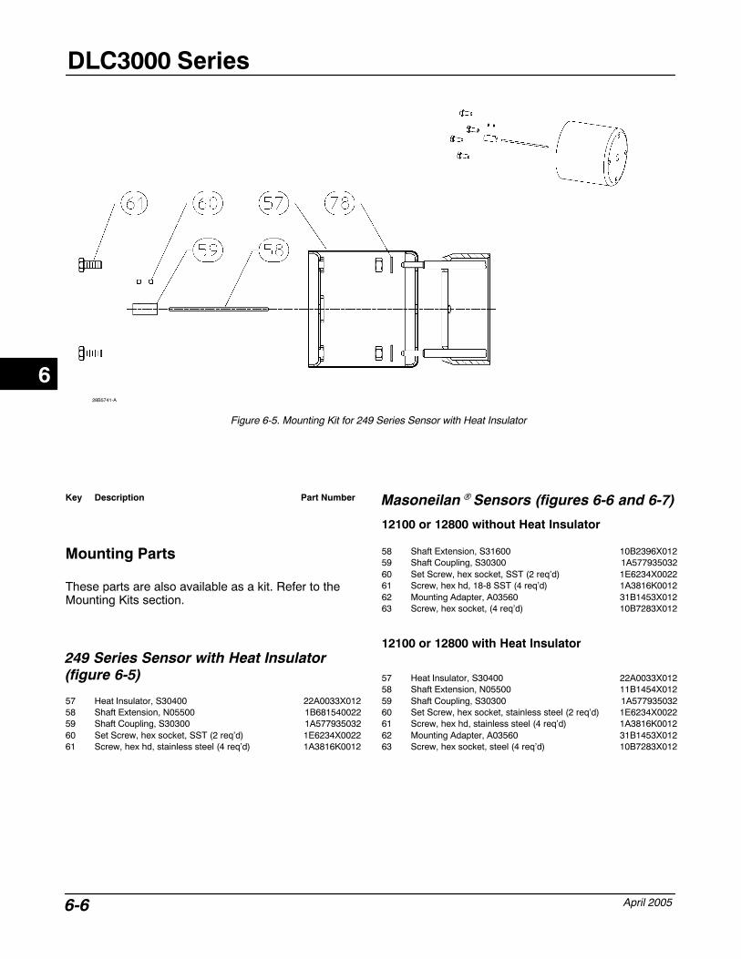
DLC3000 Series
April 20056-6
Figure 6-5. Mounting Kit for 249 Series Sensor with Heat Insulator
28B5741-A
Key Description Part Number
Mounting Parts
These parts are also available as a kit. Refer to theMounting Kits section.
249 Series Sensor with Heat Insulator(figure 6-5)
57 Heat Insulator, S30400 22A0033X01258 Shaft Extension, N05500 1B68154002259 Shaft Coupling, S30300 1A57793503260 Set Screw, hex socket, SST (2 req’d) 1E6234X002261 Screw, hex hd, stainless steel (4 req’d) 1A3816K0012
Masoneilan� Sensors (figures 6-6 and 6-7)
12100 or 12800 without Heat Insulator
58 Shaft Extension, S31600 10B2396X01259 Shaft Coupling, S30300 1A57793503260 Set Screw, hex socket, SST (2 req’d) 1E6234X002261 Screw, hex hd, 18-8 SST (4 req’d) 1A3816K001262 Mounting Adapter, A03560 31B1453X01263 Screw, hex socket, (4 req’d) 10B7283X012
12100 or 12800 with Heat Insulator
57 Heat Insulator, S30400 22A0033X01258 Shaft Extension, N05500 11B1454X01259 Shaft Coupling, S30300 1A57793503260 Set Screw, hex socket, stainless steel (2 req’d) 1E6234X002261 Screw, hex hd, stainless steel (4 req’d) 1A3816K001262 Mounting Adapter, A03560 31B1453X01263 Screw, hex socket, steel (4 req’d) 10B7283X012
6

Replaceable Parts
April 2005 6-7
Figure 6-6. Mounting Kit for Masoneilan 12200 and 12300 Sensor without Heat Insulator
29B8444-A
Figure 6-7. Mounting Kit for Masoneilan 12200 and 12300 Sensor with Heat Insulator
29B8445-A
Key Description Part Number
12200 or 12300 without Heat Insulator
58 Shaft Extension N05500 1B68154002259 Shaft Coupling, S30300 1A57793503260 Hex Socket Screw (2 req’d) 1E6234X002262 Mounting Adaptor, A92024 39B8487X01274 Hex Nut, stainless steel (4 req’d) 1A3457K001275 Hex Cap Screw, stainless steel (4 req’d) 1A3904X0032
Key Description Part Number
12200 or 12300 with Heat Insulator57 Heat Insulator, S30400 22A0033X01258 Shaft Extension N05500 19B8446X01259 Shaft Coupling, S30300 1A57793503261 Hex Cap Screw, stainless steel (4 req’d) 1A3816K001260 Hex Socket Screw (2 req’d) 1E6234X002262 Mounting Adaptor, A92024 39B8487X01274 Hex Nut, stainless steel (4 req’d) 1A3457K001275 Hex Cap Screw, stainless steel (4 req’d) 1A9304X0032
6
DLC3000 Series
April 20056-8
Key Description Part Number
Yamatake NQP Sensor
Without Heat Insulator
58 Shaft Extension, S31600 GB0099X001259 Shaft Retainer, S30400 GB0104X001260 Hex Socket Screw, stainless steel 18B5517X01262 Mounting Adaptor, A96061 GB0100X001263 Hex Socket Screw, stainless steel (3 req’d) 1J6857X001271 Hex Socket Screw, stainless steel (3 req’d) 18B5512X01272 Shaft Adapter, S30400 GB0107X001273 Hex Socket Screw, stainless steel (2 req’d) 1U8830X0012
With Heat Insulator
57 Heat Insulator, S30400 22A0033X01258 Shaft Extension, N05500 GB0103X001259 Shaft Retainer, S30400 GB0104X001260 Hex Socket Screw, stainless steel 18B5517X01261 Hex Cap Screw, stainless steel (4 req’d) 1A3816K001262 Mounting Adaptor, A96061 GB0100X001263 Hex Socket Screw, stainless steel (3 req’d) 1J6857X001271 Hex Socket Screw, stainless steel (3 req’d) 18B5512X01272 Shaft Adapter, S30400 GB0107X001273 Hex Socket Screw, stainless steel (2 req’d) 1U8830X0012
Key Description Part Number
Foxboro-Eckardt Sensors
144LD without Heat Insulator58 Shaft Extension, S31600 10B2396X01259 Shaft Coupling, S30300 19B5898X01260 Set Screw, hex socket, SST (2 req’d) 1E6234X002262 Mounting Adapter, A92024 39B5899X01274 Hex Nut, steel (4 req’d) 19A4788X01275 Hex Cap Screw, steel (4 req’d) 17B6153X012
144LD with Heat Insulator57 Heat Insulator, S30400 22A0033X01258 Shaft Extension, 316 SST 11B1454X01259 Shaft Coupling, S30300 19B5898X01260 Set Screw, hex socket, stainless steel (2 req’d) 1E6234X002261 Screw, hex hd, stainless steel (4 req’d) 1A3816K001262 Mounting Adapter, A92024 39B5899X01274 Hex Nut, steel (4 req’d) 19A4788X01275 Hex Cap Screw, steel (4 req’d) 17B6153X012
LP167 without Heat Insulator58 Shaft Extension, S31600 19B8478X01259 Shaft Coupling, S30300 19B5898X01260 Set Screw, hex socket, stainless steel (2 req’d) 1E6234X002262 Mounting Adapter, A92024 39B8479X01263 Screw, hex socket, (4 req’d) 19B8477X012
6
375 Field Communicator Basics
April 2005 A-1
Appendix A Model 375 FieldCommunicator Basics
Display A-2. . . . . . . . . . . . . . . . . . . . . . . . . . . . . . . . . . . . . . . . . . . . . . . . . . . . . . . . . . . . . . . . . . .
Using the Keypad A-2. . . . . . . . . . . . . . . . . . . . . . . . . . . . . . . . . . . . . . . . . . . . . . . . . . . . . . .
On/Off Key A-2. . . . . . . . . . . . . . . . . . . . . . . . . . . . . . . . . . . . . . . . . . . . . . . . . . . . . . . . . . . . . .
Navigation Keys A-2. . . . . . . . . . . . . . . . . . . . . . . . . . . . . . . . . . . . . . . . . . . . . . . . . . . . . . . . .
Enter Key A-2. . . . . . . . . . . . . . . . . . . . . . . . . . . . . . . . . . . . . . . . . . . . . . . . . . . . . . . . . . . . . . . .
Tab Key A-2. . . . . . . . . . . . . . . . . . . . . . . . . . . . . . . . . . . . . . . . . . . . . . . . . . . . . . . . . . . . . . . . .
Alphanumeric Keys A-2. . . . . . . . . . . . . . . . . . . . . . . . . . . . . . . . . . . . . . . . . . . . . . . . . . . . . .
Backlight Adjustment Key A-3. . . . . . . . . . . . . . . . . . . . . . . . . . . . . . . . . . . . . . . . . . . . . . . .
Function Key A-3. . . . . . . . . . . . . . . . . . . . . . . . . . . . . . . . . . . . . . . . . . . . . . . . . . . . . .
Multifunction LED A-3. . . . . . . . . . . . . . . . . . . . . . . . . . . . . . . . . . . . . . . . . . . . . . . . . .
Using the Touch Screen A-3. . . . . . . . . . . . . . . . . . . . . . . . . . . . . . . . . . . . . . . . . . . . . . . .
Using the Soft Input Panel Keyboard A-3. . . . . . . . . . . . . . . . . . . . . . . . . . . . . . . . . .
Menu Structure A-4. . . . . . . . . . . . . . . . . . . . . . . . . . . . . . . . . . . . . . . . . . . . . . . . . . . . . . . . . .
Offline Operation A-4. . . . . . . . . . . . . . . . . . . . . . . . . . . . . . . . . . . . . . . . . . . . . . . . . . . . . . . . . . Polling A-5. . . . . . . . . . . . . . . . . . . . . . . . . . . . . . . . . . . . . . . . . . . . . . . . . . . . . . . . . . . . . . . . . . System Information A-5. . . . . . . . . . . . . . . . . . . . . . . . . . . . . . . . . . . . . . . . . . . . . . . . . . . . . . . Reviewing Instrument Device Descriptions A-5. . . . . . . . . . . . . . . . . . . . . . . . . . . . . . . . . . . Simulation A-6. . . . . . . . . . . . . . . . . . . . . . . . . . . . . . . . . . . . . . . . . . . . . . . . . . . . . . . . . . . . . .
Online Operation A-6. . . . . . . . . . . . . . . . . . . . . . . . . . . . . . . . . . . . . . . . . . . . . . . . . . . . . . . .
Displaying the Field CommunicatorDevice Description Revision A-6. . . . . . . . . . . . . . . . . . . . . . . . . . . . . . . . . . . . . . . . . .
A
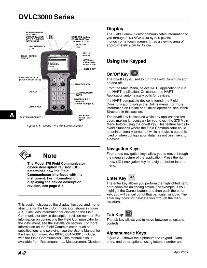
DVLC3000 Series
April 2005A-2
Figure A-1. Model 375 Field Communicator
ALPHANUMERIC KEYS
IrDA INTERFACE(TOP)
HART AND fieldbusCOMMUNICATIONTERMINALS (TOP)
TOUCH SCREENDISPLAY
NAVIGATION KEYS(FOUR ARROW KEYS)
TAB KEY
ON/OFF KEY
MULTIFUNCTION LEDBACKLIGHTADJUSTMENT KEY
POWER SUPPLYCHARGERCONNECTION (SIDE)
FUNCTION KEY
ENTER KEY
STYLUS(BACK)
OPTIONALEXPANSIONPORT (SIDE)
DLC3000: Tag
1 Process Variables
3 Basic Setup 4 Detailed Setup 5 Review
2 Diag/Service
BLINKING HEARTINDICATESCOMMUNICATIONWITH A FIELDVUEINSTRUMENT
HOTKEY
SCRATCHPAD
NoteThe Model 375 Field Communicatordevice description revision (DD)determines how the FieldCommunicator interfaces with theinstrument. For information ondisplaying the device descriptionrevision, see page A-5.
This section discusses the display, keypad, and menustructure for the Field Communicator, shown in figureA-1. It includes information for displaying the FieldCommunicator device description revision number. Forinformation on connecting the Field Communicator tothe instrument, see the Installation section. For moreinformation on the Field Communicator, such asspecifications and servicing, see the User’s Manual forthe Field Communicator 00375-0047-0001, includedwith the Field Communicator. This manual also isavailable from Rosemount Inc., Measurement Division.
Display The Field Communicator communicates information toyou through a 1/4 VGA (240 by 320 pixels)monochrome touch screen. It has a viewing area ofapproximately 9 cm by 12 cm.
Using the Keypad
On/Off Key The on/off key is used to turn the Field Communicatoron and off.
From the Main Menu, select HART Application to runthe HART application. On startup, the HARTApplication automatically polls for devices.
If a HART-compatible device is found, the FieldCommunicator displays the Online menu. For moreinformation on Online and Offline operation, see MenuStructure in this section.
The on/off key is disabled while any applications areopen, making it necessary for you to exit the 375 MainMenu before using the on/off key. This feature helps toavoid situations where the Field Communicator couldbe unintentionally turned off while a device’s output isfixed or when configuration data has not been sent toa device.
Navigation Keys Four arrow navigation keys allow you to move throughthe menu structure of the application. Press the rightarrow ( ) navigation key to navigate further into themenu.
Enter Key The enter key allows you perform the highlighted item,or to complete an editing action. For example, if youhighlight the Cancel button, and then push the enterkey, you will cancel out of that particular window. Theenter key does not navigate you through the menustructure.
Tab Key The tab key allows you to move between selectablecontrols.
Alphanumeric Keys Figure A-2 shows the alphanumeric keypad. Dataentry, and other options, using letters, number and
A
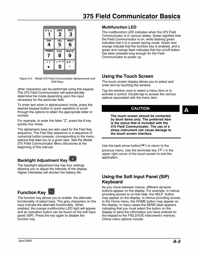
375 Field Communicator Basics
April 2005 A-3
Figure A-2. Model 375 Field Communicator Alphanumeric andShift Keys
DEF
8
GHI
9
JKL
4 5 6TUV
1
0
WXYZ
2 3# % & ABC
MNO
, ( ) ‘
Copy Paste Hot Key
Insert + Hot Key
/
-
PQRS
7
�
other characters can be performed using this keypad.The 375 Field Communicator will automaticallydetermine the mode depending upon the inputnecessary for the particular field.
To enter text when in alphanumeric mode, press thedesired keypad button in quick repetition to scrollthrough the options to attain the appropriate letter ornumber.
For example, to enter the letter “Z”, press the 9 keyquickly four times.
The alphameric keys are also used for the Fast Keysequence. The Fast Key sequence is a sequence ofnumerical button presses, corresponding to the menuoptions that lead you to a given task. See the Model375 Field Communicator Menu Structures at thebeginning of this manual.
Backlight Adjustment Key The backlight adjustment key has four settingsallowing you to adjust the intensity of the display.Higher intensities will shorten the battery life.
Function Key The function key allows you to enable the alternatefunctionality of select keys. The grey characters on thekeys indicate the alternate functionality. Whenenabled, the orange multifunction LED light will appearand an indication button can be found on the soft inputpanel (SIP). Press the key again to disable thefunction key.
Multifunction LED The multifunction LED indicates when the 375 FieldCommunicator is in various states. Green signifies thatthe Field Communicator is on, while flashing greenindicates that it is in power saving mode. Green andorange indicate that the function key is enabled, and agreen and orange flash indicates that the on/off buttonhas been pressed long enough for the FieldCommunicator to power up.
Using the Touch Screen The touch screen display allows you to select andenter text by touching the window.
Tap the window once to select a menu item or toactivate a control. Double-tap to access the variousoptions associated with the menu item.
CAUTION
The touch screen should be contactedby blunt items only. The preferred itemis the stylus that is included with the375 Field Communicator. The use of asharp instrument can cause damage tothe touch screen interface.
Use the back arrow button( ) to return to theprevious menu. Use the terminate key ( ) in theupper right corner of the touch screen to end theapplication.
Using the Soft Input Panel (SIP)Keyboard As you move between menus, different dynamicbuttons appear on the display. For example, in menusproviding access to on-line help, the HELP buttonmay appear on the display. In menus providing accessto the Home menu, the HOME button may appear onthe display. In many cases the SEND label appearsindicating that you must select the button on thedisplay to send the information you have entered onthe keypad to the FIELDVUE instrument’s memory.Online menu options include:
A
DVLC3000 Series
April 2005A-4
� Hot Key
Tap the Hot Key from any Online window to displaythe Hot Key menu. This menu allows you to quickly:
� Set instrument range values
� Perform PV setup
� Change the instrument protection
For details on ranging, PV setup, and protection, andother configuration parameters, see the DetailedSetup section of this manual.
The Hot Key can also be accessed by enabling thefunction key, and pressing the 3 key on thealphanumeric key pad.
� SCRATCHPAD is a text editor that allowsyou to create, open, edit and save simple text (.txt)documents.
� HELP—gives you information regarding thedisplay selection.
� SEND—sends the information you have enteredto the instrument.
� HOME—takes you back to the Online menu.
� EXIT—takes you back to the menu from whichyou had requested the value of a variable that canonly be read.
� ABORT—cancels your entry and takes you backto the menu from which you had selected the currentvariable or routine. Values are not changed.
� OK—takes you to the next menu or instructionscreen.
� ENTER—sends the information you haveselected to the instrument or flags the value that is tobe sent to the instrument. If it is flagged to be sent, theSEND dynamic label appears as a function keyselection.
� ESC—cancels your entry and takes you back tothe menu from which you had selected the currentvariable or routine. Values are not changed.
� SAVE—saves information to the internal flash orthe configuration expansion module.
Menu StructureThe Field Communicator is generally used in twoenvironments: offline (when not connected to aninstrument) and online (connected to an instrument).
Offline Operation Selecting HART Application when not connected to aFIELDVUE instrument causes the Field Communicatorto display the message “No device found at address 0.Poll?” Selecting “Yes” or “No” will bring you to theHART Application menu. Three choices are availablefrom this screen: Offline, Online and Utility. The Offlinemenu allows you to create offline configurations, aswell as view and change device configurations storedon the 375 Field Communicator. The Utility menuallows you to set the polling option, change thenumber of ignored status messages, view theavailable Device Descriptions, perform a simulation,and view HART diagnostics.
Do not change units in the offline mode. Changedunits will be written back to the instrument when theonline mode is entered.
You can set up a “reset to factory defaults” function forsaving a configuration of a new DLC3000. Thefunction will be labeled DLCDEFAULTS. This functionwill allow you to return to factory defaults using thehandheld communicator. Marking the Process TempOffset and Electronics Temp Offset “NOT TO SEND”will prevent you from overwriting the factorycharacterizations of these variables in an instrumentdifferent than the one you saved the configurationfrom. If you are trying to restore these values for thesame instrument, after having corrupted them in aDLC3010, you could mark them SEND. The choice ofmarking the HART data (tag, date, descriptor, etc.) atthe end NOT TO SEND is correct if you entered all thedata at one point with a handheld and don’t want tohave to recreate it.
Note that the SAVE feature allows you to create a setof standard configurations that you can load toinstruments quickly, and then go in and update just thevariable info by hand. This feature is very useful if youhave a few dozen similar installations.
Refer to the the 375 Field Communicator instructionmanual for discussion of the methods of savingconfigurations, editing configurations, and loadingsaved configurations to instruments.
Following is a list of variables that are stored in a“Saved Configuration” in the handheld memory whenyou push the SAVE button.
WriteProtectDisplacerWeightUnitsDisplacerWeightDisplacerVolumeUnits
A
375 Field Communicator Basics
April 2005 A-5
DisplacerVolumeDisplacerLengthUnitsDisplacerLengthMomentArmLengthSensorActionTorqueTubeRateUnits
TorqueTubeRateTorqueTubeMaterialprimary_variable_codePV UnitsUPPER_RANGE_VALUELOWER_RANGE_VALUEDAMPING_VALUEInputFilterLevelOffsetTempUnits
ProcTempOffset (Mark this “NOT TO SEND)ElecTempOffset (Mark this “NOT TO SEND)PV.HI_ALARMPV.HI_HI_ALARMPV.LO_ALARMPV.LO_LO_ALARMPV.DEADBANDPVAlarmEnable (packed binary)ElecTempHI_ALARMElecTempLO_ALARM
ProcTempHI_ALARMProcTempLO_ALARMTempDEADBANDTempAlarmEnable (packed binary)MeterInstalledMeterTypeMeterDecimalPointTrendVariableTrendIntervalRTDType
WireResistancetag (Mark this “NOT TO SEND” ifdesired)date (Mark this “NOT TO SEND” if desireddescriptor (Mark this “NOT TO SEND” if desired)message (Mark this “NOT TO SEND” if desired)InstrumentSerialNumber (Mark this “NOT TO SEND” ifdesired)final_assembly_number (Mark this “NOT TO SEND” ifdesired)DisplacerSerialNumber (Mark this “NOT TO SEND” ifdesired)polling_addressburst_mode_select
Polling When several devices are connected in the sameloop, such as for split ranging, each device must beassigned a unique polling address. Use the Pollingoptions to configure the Field Communicator to
automatically search for all or specific connecteddevices.
To enter a polling option, select Utility from the HARTApplication menu. Select Configure HART Application,and then select Polling. Tap ENTER to select thehighlighted option.
The Polling options are:
1. Never Poll—connects to a device at address 0,and if not found will not poll for devices at addresses 1through 15.
2. Ask Before Polling—connects to a device ataddress 0, and if not found asks if you want to poll fordevices at addresses 1 through 15.
3. Always Poll—connects to a device at address 0,and if not found will automatically poll for devices ataddresses 1 through 15.
4. Digital Poll—automatically polls for devices ataddress 0 through 15 and lists devices found by tag.
5. Poll Using Tag—asks for a device HART tag andthen polls for that device.
6. Poll Using Long Tag—allows you to enter thelong tag of the device. (Only supported in HARTUniversal revision 6 devices.)
To find individual device addresses, use the DigitalPoll option to find each connected device in the loopand list them by tag.
For more information on setting the polling address,see the Detailed Setup section.
System Information To access the Field Communicator systeminformation, select Settings from the 375 Main Menu.
About 375 includes software information about your375 Field Communicator.
Licensing can be viewed when you turn on the 375Field Communicator and in the License settings menu.The license setting allows you to view the license onthe System Card.
Memory settings consists of System Card, InternalFlash size, and Ram size, as well as the ExpansionModule if installed. It allows you to view the totalmemory storage and available free space.
Reviewing Instrument DeviceDescriptionsThe Field Communicator memory module containsdevice descriptions for specific HART-compatibledevices. These descriptions make up the applicationsoftware that the communicator needs to recognizeparticular devices.
To review the device descriptions programmed intoyour Field Communicator, select Utility from the HART
A
DVLC3000 Series
April 2005A-6
Application menu, then select Available DeviceDescriptions. The manufacturers with devicedescriptions installed on the Field Communicator arelisted.
Select the desired manufacturer to see the list of thecurrently installed device models, or types, providedby the selected manufacturer.
Select the desired instrument model or type to see theavailable device revisions that support that instrument.
Simulation The Field Communicator provides a simulation modethat allows you to simulate an online connection to aHART-compatible device. The simulation mode is atraining tool that enables you to become familiar withthe various menus associated with a device withouthaving the Field Communicator connected to thedevice.
To simulate an online connection, select Utility fromthe main menu. Select Simulation then select FisherControls. Select DLC3000 to see the menu structurefor the DLC3000 Series digital valve controller. Referto the appropriate sections of this manual forinformation on the various menus.
Online Operation The Online menu is the first to be displayed whenconnecting to a HART compatible device. It containsimportant information about the connected device.
The figure on the front cover foldout shows anoverview of the DLC3000 Series digital valve controllermenu structure.
Displaying the Field CommunicatorDevice Description Revision Device Description (DD) Revision is the revisionnumber of the Fisher Device Description that residesin the Field Communicator. It defines how the FieldCommunicator is to interact with the user andinstrument.
Field Communicators with device description revision2 are used with DVC3000 Series instruments. You candisplay the device description revision when the FieldCommunicator is Offline or Online: to see the FieldCommunicator device description revision numberfrom the Offline menu, select Utility, Simulation, FisherControls, and DLC3000. From the Online menu, selectDetailed Setup, Device Information, Version Info, andDevice Description (4-3-2-5).
A
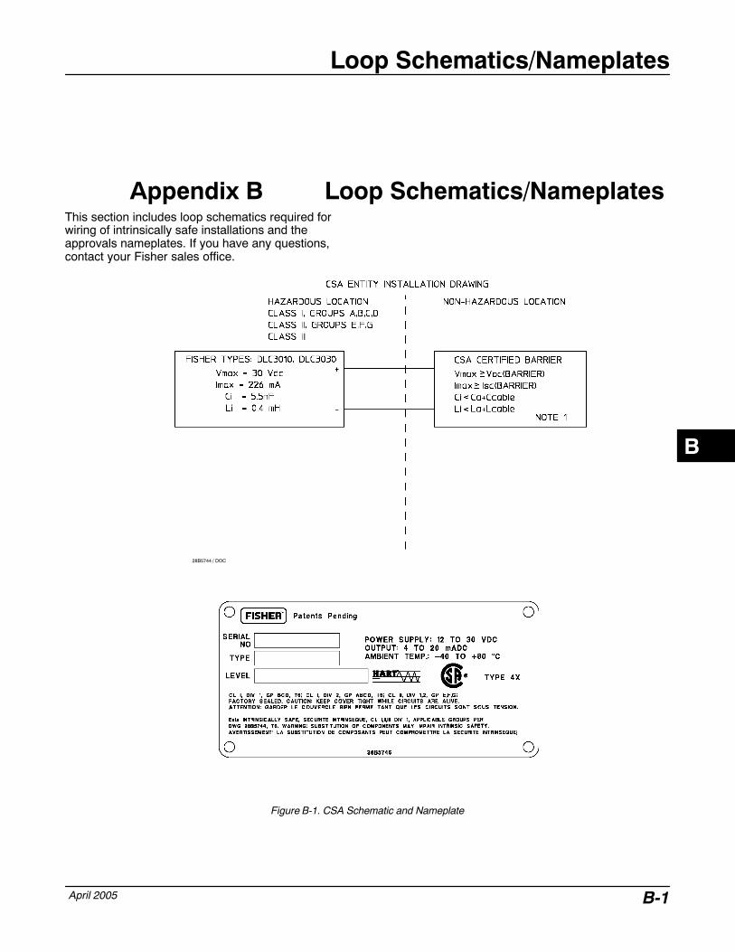
Loop Schematics/Nameplates
April 2005 B-1
Appendix B Loop Schematics/NameplatesThis section includes loop schematics required forwiring of intrinsically safe installations and theapprovals nameplates. If you have any questions,contact your Fisher sales office.
28B5744 / DOC
Figure B-1. CSA Schematic and Nameplate
B
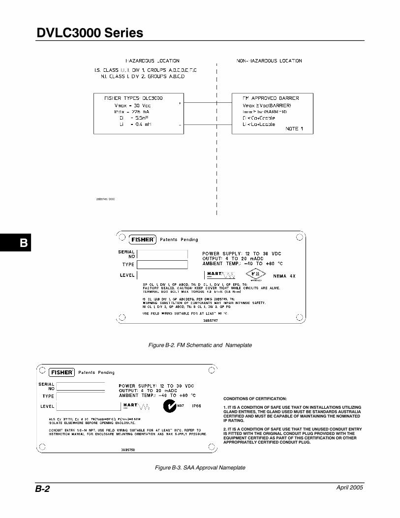
DVLC3000 Series
April 2005B-2
28B5745 / DOC
Figure B-2. FM Schematic and Nameplate
CONDITIONS OF CERTIFICATION:
1. IT IS A CONDITION OF SAFE USE THAT ON INSTALLATIONS UTILIZINGGLAND ENTRIES, THE GLAND USED MUST BE STANDARDS AUSTRALIACERTIFIED AND MUST BE CAPABLE OF MAINTAINING THE NOMINATEDIP RATING.
2. IT IS A CONDITION OF SAFE USE THAT THE UNUSED CONDUIT ENTRYIS FITTED WITH THE ORIGINAL CONDUIT PLUG PROVIDED WITH THEEQUIPMENT CERTIFIED AS PART OF THIS CERTIFICATION OR OTHERAPPROPRIATELY CERTIFIED CONDUIT PLUG.
Figure B-3. SAA Approval Nameplate
B
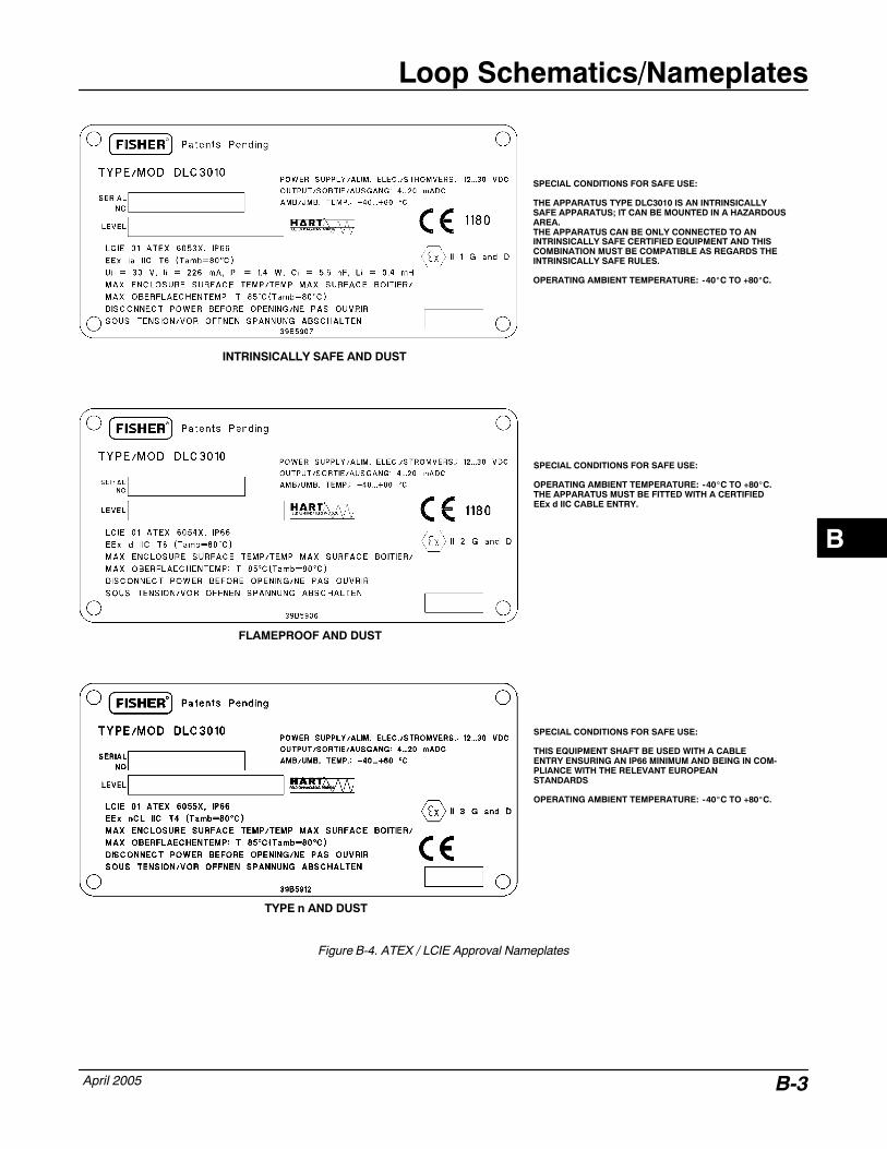
Loop Schematics/Nameplates
April 2005 B-3
TYPE n AND DUST
FLAMEPROOF AND DUST
INTRINSICALLY SAFE AND DUST
SPECIAL CONDITIONS FOR SAFE USE:
THE APPARATUS TYPE DLC3010 IS AN INTRINSICALLYSAFE APPARATUS; IT CAN BE MOUNTED IN A HAZARDOUSAREA.THE APPARATUS CAN BE ONLY CONNECTED TO AN INTRINSICALLY SAFE CERTIFIED EQUIPMENT AND THISCOMBINATION MUST BE COMPATIBLE AS REGARDS THEINTRINSICALLY SAFE RULES.
OPERATING AMBIENT TEMPERATURE: -40�C TO +80�C.
SPECIAL CONDITIONS FOR SAFE USE: OPERATING AMBIENT TEMPERATURE: -40�C TO +80�C.THE APPARATUS MUST BE FITTED WITH A CERTIFIEDEEx d IIC CABLE ENTRY.
SPECIAL CONDITIONS FOR SAFE USE:
THIS EQUIPMENT SHAFT BE USED WITH A CABLEENTRY ENSURING AN IP66 MINIMUM AND BEING IN COM-PLIANCE WITH THE RELEVANT EUROPEAN STANDARDS OPERATING AMBIENT TEMPERATURE: -40�C TO +80�C.
Figure B-4. ATEX / LCIE Approval Nameplates
B
DVLC3000 Series
April 2005B-4
B
Glossary
April 2005 Glossary-1
Glossary
Alarm DeadbandThe amount by which the process variable mustreturn within normal limits for the alarm to clear.
Alarm LimitAn adjustable value that, when exceeded,activates an alert.
AlgorithmA set of logical steps to solve a problem oraccomplish a task. A computer program containsone or more algorithms.
AlphanumericConsisting of letters and numbers.
ANSI (acronym)The acronym ANSI stands for the AmericanNational Standards Institute
BurstBurst mode is an extension to HART protocol thatprovides the continuous transmission of standardHART command response by a field device.
ByteA unit of binary digits (bits). A byte consists ofeight bits.
CommissioningFunctions performed with a Field Communicatorand the digital level controller to test theinstrument and loop and verify digital levelcontroller configuration data.
ConfigurationStored instructions and operating parameters fora FIELDVUE Instrument.
Control LoopAn arrangement of physical and electroniccomponents for process control. The electroniccomponents of the loop continuously measureone or more aspects of the process, then alterthose aspects as necessary to achieve a desiredprocess condition. A simple control loopmeasures only one variable. More sophisticatedcontrol loops measure many variables andmaintain specified relationships among thosevariables.
DampingOutput function that increases the time constantof the digital level controller output to smooth theoutput when there are rapid input variations.
DescriptorSixteen-character field for additional identificationof the digital level controller, its use, or location.The descriptor is stored in the instrument and canbe changed using a Field Communicator and thedevice information function.
Device IDUnique identifier embedded in the instrument atthe factory.
Device RevisionRevision number of the interface software thatpermits communication between the FieldCommunicator and the instrument.
Firmware RevisionThe revision number of the instrument firmware.Firmware is a program that is entered into theinstrument at time of manufacture and cannot bechanged by the user.
9Glossary
DLC3000 Series
April 2005Glossary-2
Free TimePercent of time that the microprocessor is idle. Atypical value is 25%. The actual value dependson the number of functions in the instrument thatare enabled and on the amount of communicationcurrently in progress.
GainThe ratio of output change to input change.
Hardware RevisionRevision number of the Fisher instrumenthardware. The physical components of theinstrument are defined as the hardware.
HART (acronym)The acronym HART stands for HighwayAddressable Remote Transducer. Thecommunications standard that providessimultaneous analog and digital signaltransmission between control rooms and fielddevices.
HART TagAn eight-character field for identifying the digitallevel controller. The HART tag is stored in theinstrument and can be changed using a FieldCommunicator and the device informationfunction.
HART Universal RevisionRevision number of the HART UniversalCommands which are the communicationsprotocol for the instrument.
Instrument Serial NumberThe serial number assigned to the instrument.
Lower Range Value (LRV)Lowest value of the process variable that thedigital level controller is currently configured tomeasure in the 4 to 20 mA loop.
Lower Sensor Limit (LSL)Lowest value of the process variable that thedigital level controller can be configured tomeasure.
MemoryA type of semiconductor used for storingprograms or data. FIELDVUE instruments usethree types of memory: Random Access Memory(RAM), Read Only Memory (ROM), andNon-Volatile Memory (NVM). See also theselistings in this glossary.
MenuA list of programs, commands, or other activitiesthat you select by using the arrow keys tohighlight the item then pressing ENTER, or byentering the numeric value of the menu item.
MessageTwenty-four character field for any additionalinformation the user may want to include.
MultidroppingThe connection of several field devices to a singlecommunications transmission line.
Non-Volatile Memory (NVM)A type of semiconductor memory that retains itscontents even though power is disconnected.NVM contents can be changed duringconfiguration unlike ROM which can be changedonly at time of instrument manufacture. NVMstores configuration data.
On-Line ConfigurationConfiguration of the digital level controlleroperational parameters using a FieldCommunicator connected to the instrument.
ParallelSimultaneous: said of data transmission on two ormore channels at the same time.
Polling AddressAddress of the instrument. If the digital valvecontroller is used in a point-to-point configuration,set the polling address to 0. If it is used in amultidrop configuration, or split range application,set the polling address to a value from 0 to 15.
Process Variable (PV)A physical quality or quantity which is monitoredas part of a control strategy. The digital levelcontroller can measure level, interface levelbetween two liquids of different specific gravity,and liquid density.
9Glossary
Glossary
April 2005 Glossary-3
ProtocolA set of data formats and transmission rules forcommunication between electronic devices.Devices that conform to the same protocol cancommunicate accurately.
Random Access Memory (RAM)A type of semiconductor memory that is normallyused by the microprocessor during normaloperation that permits rapid retrieval and storageof programs and data. See also Read OnlyMemory (ROM) and Non-Volatile Memory (NVM).
Read-Only Memory (ROM)A memory in which information is stored at thetime of instrument manufacture. You canexamine but not change ROM contents.
RerangingConfiguration function that changes the digitallevel controller 4 to 20 mA settings.
RTDThe abbreviation for resistance temperaturedetector. Temperature is measured by the RTDby correlating the resistance of the RTD elementwith temperature.
Send DataA Field Communicator command that transfersconfiguration data from the Field Communicator’sworking register to the digital level controllermemory.
SoftwareMicroprocessor or computer programs androutines that reside in alterable memory (usuallyRAM), as opposed to firmware, which consists ofprograms and routines that are programmed intomemory (usually ROM) when the instrument ismanufactured. Software can be manipulatedduring normal operation, firmware cannot.
SpanAlgebraic difference between the upper and lowerrange values.
Temperature SensorA device within the instrument that measures theinstrument’s internal temperature.
Upper Range Value (URV)Highest value of the process variable that thedigital level controller is currently configured tomeasure in the 4 to 20 mA loop.
Upper Sensor Limit (USL)Highest value of the process variable that thedigital level controller can be configured tomeasure.
Working RegisterMemory location in a Field Communicator thattemporarily stores data as it is being entered.
9Glossary
DLC3000 Series
April 2005Glossary-4
Notes
9Glossary
Index
April 2005 Index-1
A
Alarm Jumper, 3−12Changing Position, 3−12Displaying Output Action, 5−6, 5−8
AlarmsDisplaying, 5−7Enabling
Process Variable, 4−27Temperature, 4−27
Hardware, Displaying, 5−8Setting Limits
Process Variable, 4−26Temperature, 4−26
AMS Suite: Intelligent Device Manager, 1−2
B
Burst Operation, 3−14
C
CalibrationPV Sensor Calibration, 4−8Quick Calibration, 4−8Scaled D/A Trim, 4−14Temperature, 4−13
Calibration , 4−8PV Sensor, Procedures that Affect the Zero of the PV
CalculationMark Dry Coupling, 4−9Trim PV Zero, 4−9
Coupling, 4−7
D
D/A Trim, Scaled. See Calibration
Damping. See Process Variable Damping
Date, 4−28
Descriptor, 4−28
Device Id, 5−7
Displacer Data, 4−20Length, 4−20Rod Length, 4−20Serial Number, 5−7Units, 4−20Volume, 4−20Weight, 4−20
DLC3000 SeriesDescription, 1−2Installation. See InstallationPrinciple of Operation, 2−2Removing from the Sensor, 5−9Specifications, 1−3Testing, 5−8
E
Educational Services, 1−3
Electrical Connections, 3−8
Electronics Assembly, Part Number, 6−3
Electronics ModuleRemoving, 5−12Replacing, 5−13
F
Field CommunicatorAlphanumeric Keypad, A−2Backlight Adjustment Key, A−3Device Description Revision, A−6Display, A−2Enter Key, A−2Function Key, A−3Hot Key, A−4Multifunction LED, A−3Navigation Keys, A−2Offline Menu, A−4On/Off Key, A−2Online Menu, A−6Online Simulation, A−6Polling, A−5Scratchpad, A−4Soft Input Panel Keyboard (SIP), A−3Specifications, A−2System Information, A−5
AIndexIndex
DLC3000 Series
April 2005Index-2
Tab Key, A−2Using the Touch Screen, A−3
Final Assembly Number, 5−7
G
Grounding, 3−10Shielded Wire, 3−10
H
Hardware Diagnostics, 5−5
HART Communication, Principle of Operation, 2−2
HART Tag, 4−28
HART Tri − Loop, Configuring DLC3000 for use with,3−13
Heat Insulator, Installation, 3−6
Hot Key, Field Communicator, A−4
I
Initial Setup, 4−4
Inner Guide and Access Handle Assembly, Removingand Replacing, 5−14
Input Filter, 4−24
InstallationDLC3010 on 249 Series Sensor, 3−5Electrical, 3−8Field Wiring, 3−9Heat Insulator, 3−6Multichannel, 3−11Of 249 Series Sensor, 3−4Power/Current Loop Connections, 3−10RTD Connections, 3−10
Instrument Mounting, Specifying, 4−20
Instrument Serial Number, 5−7
Instrument Status, 5−8
L
LCD MeterDiagnostic Messages, 5−3Part Number, 6−3Removing, 5−11Replacing, 5−11
Setup, 4−25Testing, 4−25
Level Offset, 4−5
Level Sensor Drive Signal, 5−8
Lever Assembly, 5−15Removing, 5−15Replacing, 5−15
Loop Test, 3−12
M
Message, 4−28
Model 375 Field Communicator, 1−2
Mounting, 3−2249 Series Sensor, 3−4Digital Level Controller Orientation, 3−5DLC3010, On 249 Series Sensor, 3−5
Mounting Kits, 6−2
Multichannel Installations, 3−11
Multidropped Communication, Typical MultidroppedNetwork, 4−29
P
Packing for Shipment, 5−16
Parts, Ordering, 6−2
Parts Kits, 6−2
Polling Address, 4−28
Power Supply, Load Limits, 3−8
Power/Current Loop Connections, 3−10
Process VariableDamping, 4−23Offset, 4−23Range, 4−21Selecting, 4−21Units, 4−21
Protection, 4−5, 4−20
R
Range Values, 4−22
Related Documents, 1−3
Revision Information, Field Communicator, DeviceDescription, A−6
RTDConnections, 3−10
AIndex
Index
April 2005 Index-3
Setup, 4−21
S
Serial NumberDisplacer, 5−7Instrument, 5−7
Setting Zero and Span, 4−22
Setup Wizard, 4−5
Specifications, 1−3
Specific GravityEntering, 4−24Measuring, 5−6
Status. See Instrument Status
T
TemperatureElectronics, 5−5
Process, 4−20Units, 4−21
Terminal Box, 5−13Removing, 5−13Replacing, 5−14
Test Terminals, 3−11, 5−5
Torque Tube DataMaterial, 4−20Temperature Coefficient, 4−20
W
Write Lock, 4−5See also Protection
Z
Zero and Span. See Setting Zero and Span
AIndex
DLC3000 Series
April 2005Index-4
AIndex

Fisher
Marshalltown, Iowa 50158 USA
Cernay 68700 France
Sao Paulo 05424 Brazil
Singapore 128461
The contents of this publication are presented for informational purposes only, and while every effort has been made to ensure their accuracy, theyare not to be construed as warranties or guarantees, express or implied, regarding the products or services described herein or their use or applicability. We reserve the right to modify or improve the designs or specifications of such products at any time without notice.
Neither Emerson, Emerson Process Management, nor Fisher assume responsibility for the selection, use or maintenance of any product. Responsibility for proper selection, use and maintenance of any Fisher product remains solely with the purchaser and end-user.
�Fisher Controls International, LLC 2000, 2005; All Rights Reserved Printed in USA
FIELDVUE, ValveLink and Fisher are marks owned by Fisher Controls International LLC, a member of the Emerson Process Management business division of Emerson Electric Co. DeltaV and Tri-Loop are marks owned by one of the companies in the Emerson Process Managementbusiness division of Emerson Electric Co. Emerson and the Emerson logo are trademarks and service marks of Emerson Electric Co. HART is amark owned by the HART Communications Foundation. All other marks are the property of their respective owners.
Emerson Process Management
www.Fisher.com