diy speaker kit - manual - farnell element14 · diy speaker kit - manual. welcome to the diy...
TRANSCRIPT
DIYSpeaker Kit - Manual
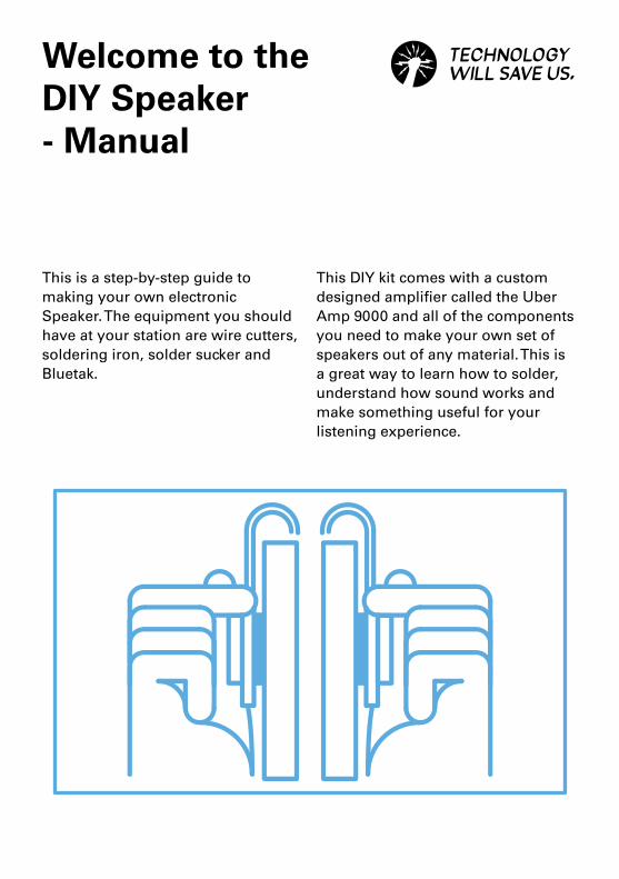
Welcome to the DIY Speaker- Manual
This is a step-by-step guide to making your own electronic Speaker. The equipment you should have at your station are wire cutters, soldering iron, solder sucker and Bluetak.
This DIY kit comes with a custom designed amplifier called the Uber Amp 9000 and all of the components you need to make your own set of speakers out of any material. This is a great way to learn how to solder, understand how sound works and make something useful for your listening experience.
3DIY Speaker - Manual
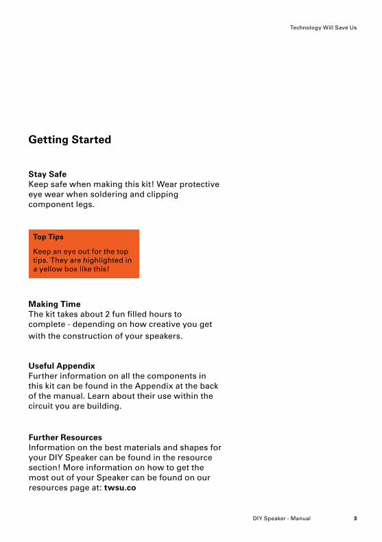
Getting Started
Top Tips
Keep an eye out for the top tips. They are highlighted in a yellow box like this!
Useful Appendix Further information on all the components in this kit can be found in the Appendix at the back of the manual. Learn about their use within the circuit you are building.
Making Time The kit takes about 2 fun filled hours to complete - depending on how creative you get with the construction of your speakers.
Stay Safe Keep safe when making this kit! Wear protective eye wear when soldering and clipping component legs.
Technology Will Save Us
Further Resources Information on the best materials and shapes for your DIY Speaker can be found in the resource section! More information on how to get the most out of your Speaker can be found on our resources page at: twsu.co
DIY Speaker - Manual4
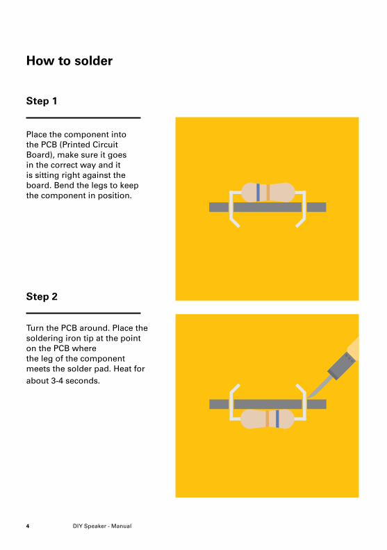
How to solder
Turn the PCB around. Place the soldering iron tip at the point on the PCB where the leg of the component meets the solder pad. Heat for about 3-4 seconds.
Place the component into the PCB (Printed Circuit Board), make sure it goes in the correct way and it is sitting right against the board. Bend the legs to keep the component in position.
Step 1
Step 2

5DIY Speaker - Manual
Using your other hand, add solder to the heated pad. Add enough solder to cover the pad and the base of the components leg. Remove the solder and leave the iron for another second.
After soldering both legs, take your side cutters and remove the excess component leg. If you make a mistake, re-heat the join and use a solder sucker to remove the molten solder.
Technology Will Save Us
Step 3
Step 4
DIY Speaker - Manual6
Making your DIY Speaker
Components
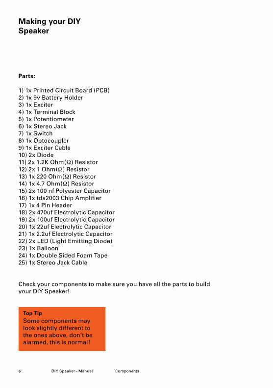
Parts:
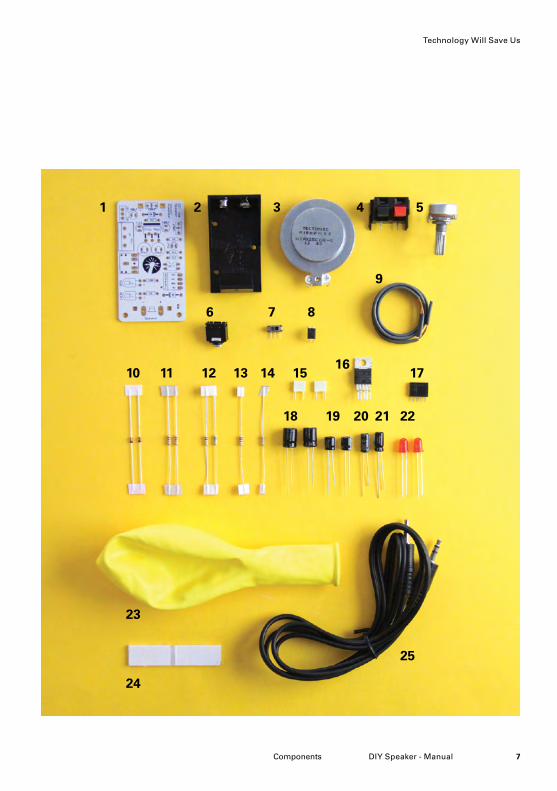
1) 1x Printed Circuit Board (PCB) 2) 1x 9v Battery Holder3) 1x Exciter 4) 1x Terminal Block5) 1x Potentiometer6) 1x Stereo Jack7) 1x Switch8) 1x Optocoupler9) 1x Exciter Cable10) 2x Diode11) 2x 1.2K Ohm(Ω) Resistor12) 2x 1 Ohm(Ω) Resistor13) 1x 220 Ohm(Ω) Resistor 14) 1x 4.7 Ohm(Ω) Resistor15) 2x 100 nf Polyester Capacitor16) 1x tda2003 Chip Amplifier17) 1x 4 Pin Header18) 2x 470uf Electrolytic Capacitor19) 2x 100uf Electrolytic Capacitor20) 1x 22uf Electrolytic Capacitor21) 1x 2.2uf Electrolytic Capacitor22) 2x LED (Light Emitting Diode)23) 1x Balloon24) 1x Double Sided Foam Tape 25) 1x Stereo Jack Cable
Check your components to make sure you have all the parts to build your DIY Speaker!
Top Tip
Some components may look slightly different to the ones above, don’t be alarmed, this is normal!
7DIY Speaker - ManualComponents
1 2
6
10
23
24
11 12 13 14 15
18 19 20 21 22
25
1716
7 8
3 4 5
9
Technology Will Save Us
DIY Speaker - Manual8
1
Step 1
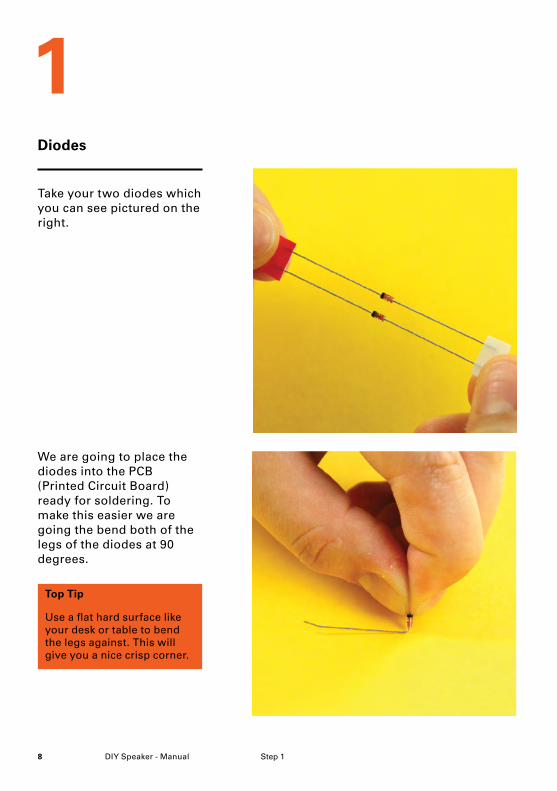
Diodes
Take your two diodes which you can see pictured on the right.
We are going to place the diodes into the PCB (Printed Circuit Board) ready for soldering. To make this easier we are going the bend both of the legs of the diodes at 90 degrees.
Top Tip
Use a flat hard surface like your desk or table to bend the legs against. This will give you a nice crisp corner.
9DIY Speaker - ManualStep 1
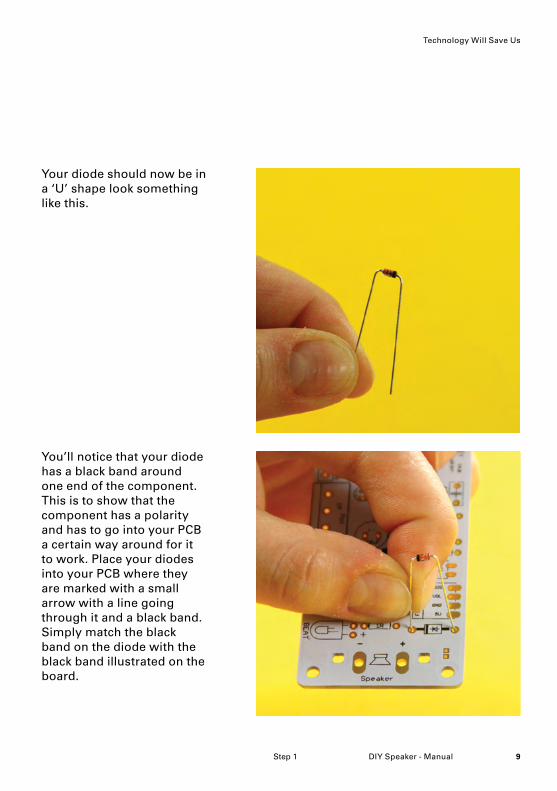
Your diode should now be in a ‘U’ shape look something like this.
You’ll notice that your diode has a black band around one end of the component. This is to show that the component has a polarity and has to go into your PCB a certain way around for it to work. Place your diodes into your PCB where they are marked with a small arrow with a line going through it and a black band. Simply match the black band on the diode with the black band illustrated on the board.
Technology Will Save Us
DIY Speaker - Manual10 Step 1
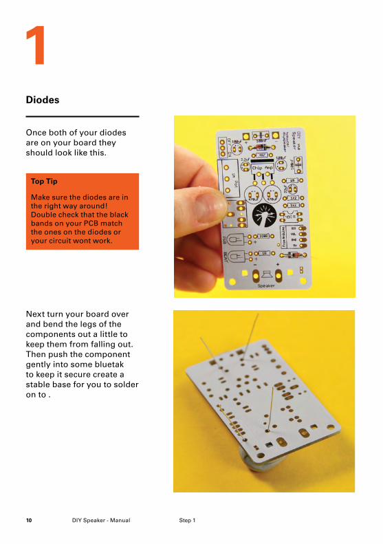
Once both of your diodes are on your board they should look like this.
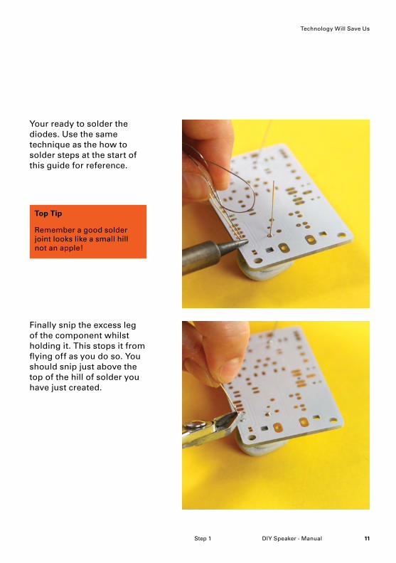
Next turn your board over and bend the legs of the components out a little to keep them from falling out. Then push the component gently into some bluetak to keep it secure create a stable base for you to solder on to .
Top Tip
Make sure the diodes are in the right way around! Double check that the black bands on your PCB match the ones on the diodes or your circuit wont work.
1Diodes
11DIY Speaker - Manual
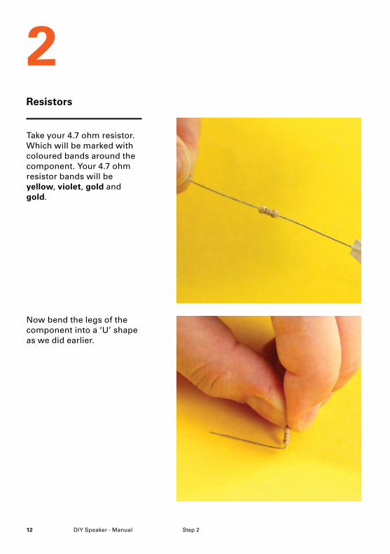
Top Tip
Remember a good solder joint looks like a small hill not an apple!
Step 1
Your ready to solder the diodes. Use the same technique as the how to solder steps at the start of this guide for reference.
Finally snip the excess leg of the component whilst holding it. This stops it from flying off as you do so. You should snip just above the top of the hill of solder you have just created.
Technology Will Save Us
DIY Speaker - Manual12
2
Step 2
Resistors
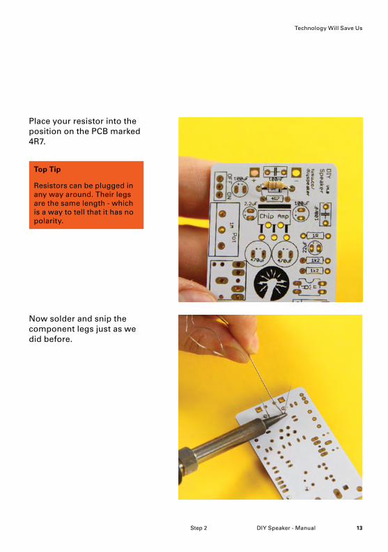
Take your 4.7 ohm resistor. Which will be marked with coloured bands around the component. Your 4.7 ohm resistor bands will be yellow, violet, gold and gold.
Now bend the legs of the component into a ‘U’ shape as we did earlier.
13DIY Speaker - Manual
Top Tip
Resistors can be plugged in any way around. Their legs are the same length - which is a way to tell that it has no polarity.
Step 2
Place your resistor into the position on the PCB marked 4R7.
Now solder and snip the component legs just as we did before.
Technology Will Save Us

DIY Speaker - Manual14 Step 2
Now bend the resistors legs and place them into the board where their position is marked with a 1R symbol.
The next resistors you need are your 1 ohm resistors. Which will be marked with the following bands; brown, black, gold, gold.
2Resistors
15DIY Speaker - Manual
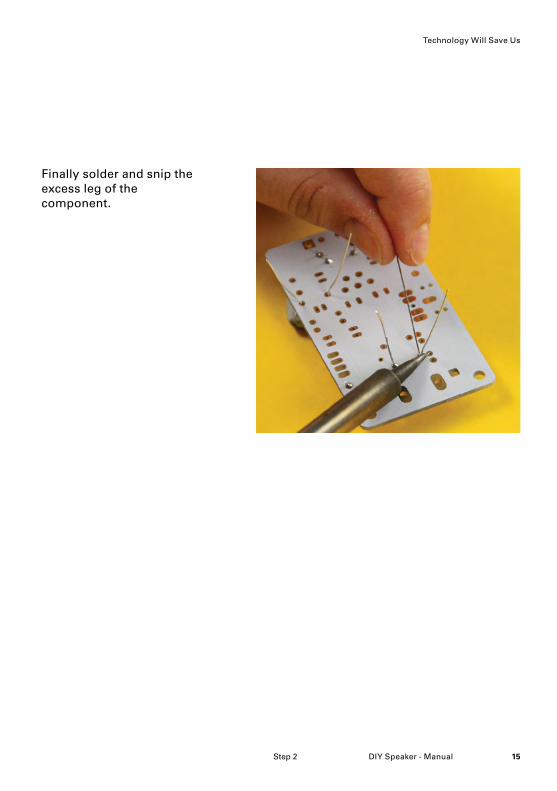
Finally solder and snip the excess leg of the component.
Step 2
Technology Will Save Us
DIY Speaker - Manual16 Step 2
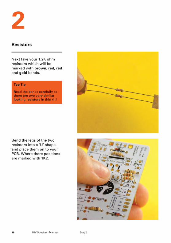
Next take your 1.2K ohm resistors which will be marked with brown, red, red and gold bands.
Bend the legs of the two resistors into a ‘U’ shape and place them on to your PCB. Where there positions are marked with 1K2.
2Resistors
Top Tip
Read the bands carefully as there are two very similar looking resistors in this kit!
17DIY Speaker - Manual
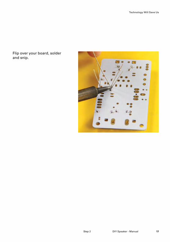
Flip over your board, solder and snip.
Step 2
Technology Will Save Us
DIY Speaker - Manual18
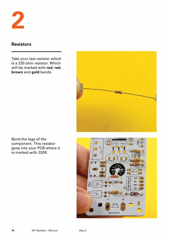
Bend the legs of the component. This resistor goes into your PCB where it is marked with 220R.
Take your last resistor which is a 220 ohm resistor. Which will be marked with red, red, brown and gold bands.
Step 2
2Resistors
19DIY Speaker - Manual
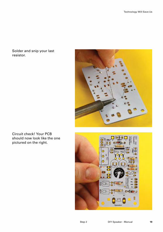
Circuit check! Your PCB should now look like the one pictured on the right.
Solder and snip your last resistor.
Step 2
Technology Will Save Us
DIY Speaker - Manual20 Step 3
Capacitors
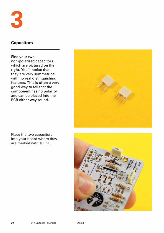
Place the two capacitors into your board where they are marked with 100nF.
Find your two non-polarized capacitors which are pictured on the right. You’ll notice that they are very symmetrical with no real distinguishing features. This is often a very good way to tell that the component has no polarity and can be placed into the PCB either way round.
3
21DIY Speaker - Manual
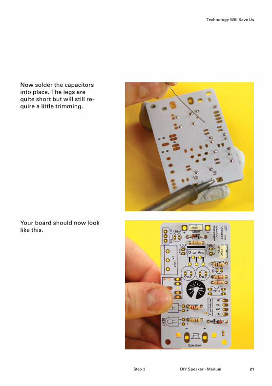
Your board should now look like this.
Now solder the capacitors into place. The legs are quite short but will still re-quire a little trimming.
Step 3
Technology Will Save Us
DIY Speaker - Manual22 Step 4
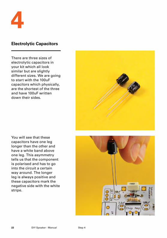
You will see that these capacitors have one leg longer than the other and have a white band above one leg. This asymmetry tells us that the component is polarised and has to go into the circuit a certain way around. The longer leg is always positive and these capacitors mark the negative side with the white stripe.
There are three sizes of electrolytic capacitors in your kit which all look similar but are slightly different sizes. We are going to start with the 100uF capacitors which physically, are the shortest of the three and have 100uF written down their sides.
Electrolytic Capacitors
4
23DIY Speaker - Manual
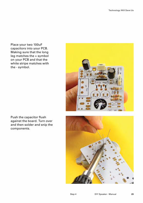
Push the capacitor flush against the board. Turn over and then solder and snip the components.
Place your two 100uF capacitors into your PCB. Making sure that the long leg matches the + symbol on your PCB and that the white stripe matches with the - symbol.
Step 4
Technology Will Save Us
DIY Speaker - Manual24
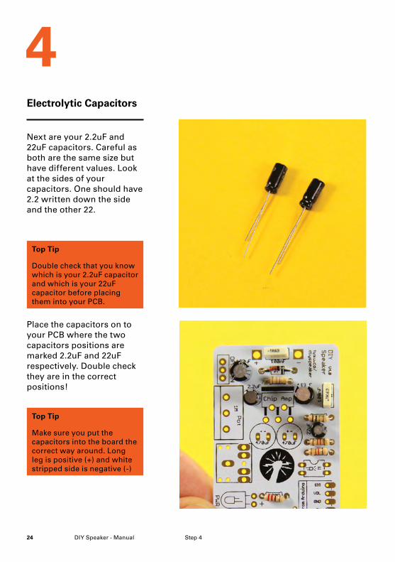
Place the capacitors on to your PCB where the two capacitors positions are marked 2.2uF and 22uF respectively. Double check they are in the correct positions!
Next are your 2.2uF and 22uF capacitors. Careful as both are the same size but have different values. Look at the sides of your capacitors. One should have 2.2 written down the side and the other 22.
Step 4
Electrolytic Capacitors
4
Top Tip
Make sure you put the capacitors into the board the correct way around. Long leg is positive (+) and white stripped side is negative (-)
Top Tip
Double check that you know which is your 2.2uF capacitor and which is your 22uF capacitor before placing them into your PCB.
25DIY Speaker - Manual
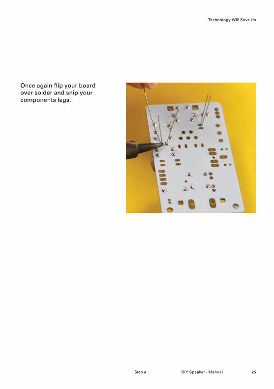
Once again flip your board over solder and snip your components legs.
Step 4
Technology Will Save Us
DIY Speaker - Manual26
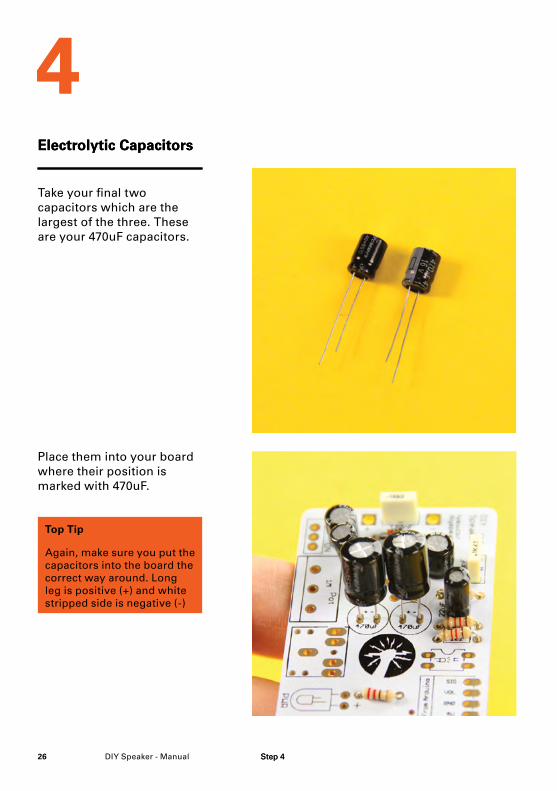
Place them into your board where their position is marked with 470uF.
Take your final two capacitors which are the largest of the three. These are your 470uF capacitors.
Step 4
Electrolytic Capacitors
4
Top Tip
Again, make sure you put the capacitors into the board the correct way around. Long leg is positive (+) and white stripped side is negative (-)
Step 4
Electrolytic Capacitors
4
27DIY Speaker - Manual
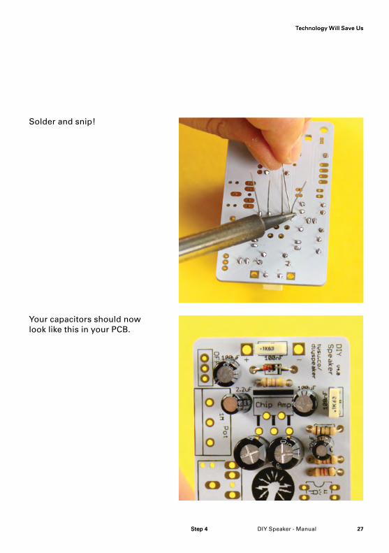
Your capacitors should now look like this in your PCB.
Solder and snip!
Step 4
Technology Will Save Us
Step 4
Technology Will Save Us
DIY Speaker - Manual28
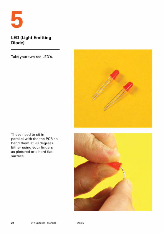
These need to sit in parallel with the the PCB so bend them at 90 degrees. Either using your fingers as pictured or a hard flat surface.
Take your two red LED’s.
Step 5
LED (Light Emitting Diode)
5
29DIY Speaker - Manual
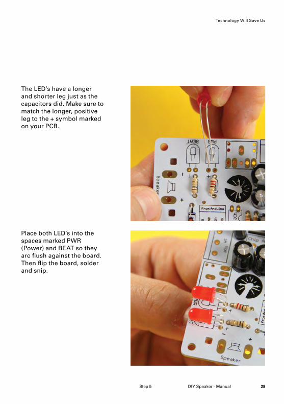
Place both LED’s into the spaces marked PWR (Power) and BEAT so they are flush against the board. Then flip the board, solder and snip.
The LED’s have a longer and shorter leg just as the capacitors did. Make sure to match the longer, positive leg to the + symbol marked on your PCB.
Step 5
Technology Will Save Us
DIY Speaker - Manual30 Step 6
IC (Integrated Circuit)
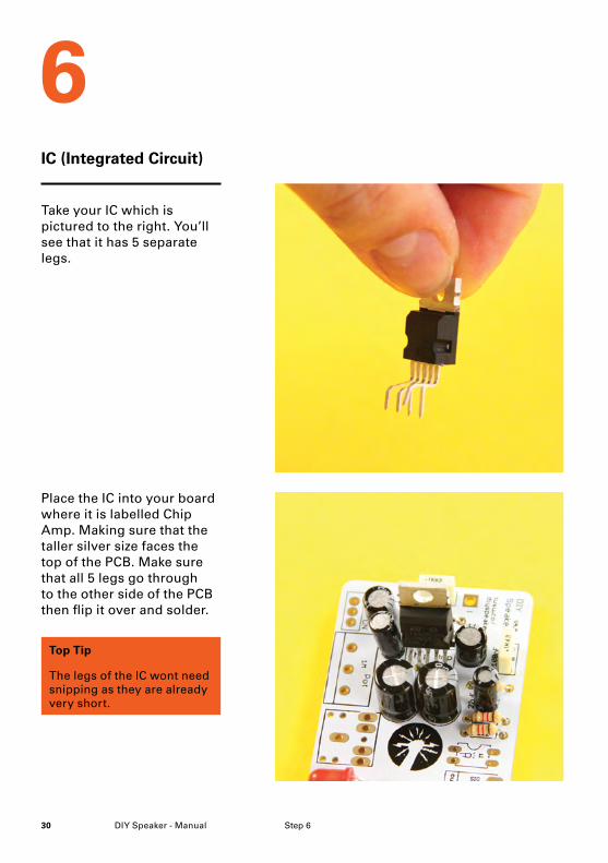
Place the IC into your board where it is labelled Chip Amp. Making sure that the taller silver size faces the top of the PCB. Make sure that all 5 legs go through to the other side of the PCB then flip it over and solder.
Take your IC which is pictured to the right. You’ll see that it has 5 separate legs.
6
Top Tip
The legs of the IC wont need snipping as they are already very short.
31DIY Speaker - Manual
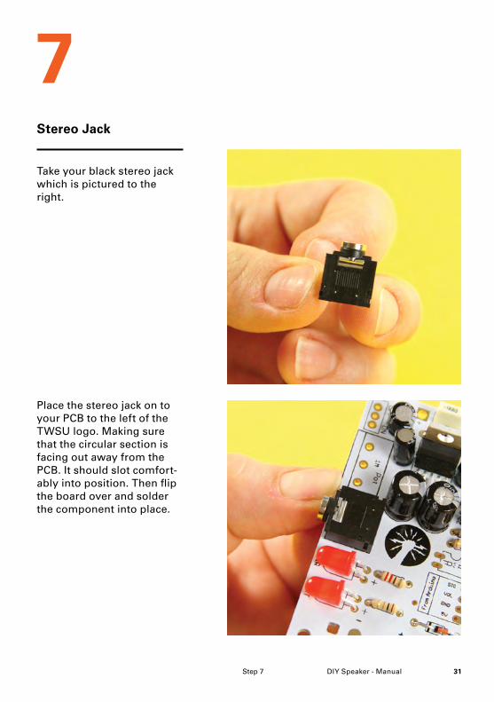
Stereo Jack
Place the stereo jack on to your PCB to the left of the TWSU logo. Making sure that the circular section is facing out away from the PCB. It should slot comfort-ably into position. Then flip the board over and solder the component into place.
Take your black stereo jack which is pictured to the right.
7
Step 7
DIY Speaker - Manual32 Step 8
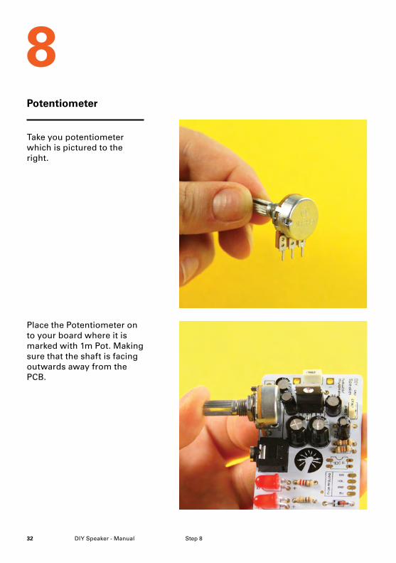
Potentiometer
Place the Potentiometer on to your board where it is marked with 1m Pot. Making sure that the shaft is facing outwards away from the PCB.
Take you potentiometer which is pictured to the right.
8
33DIY Speaker - Manual
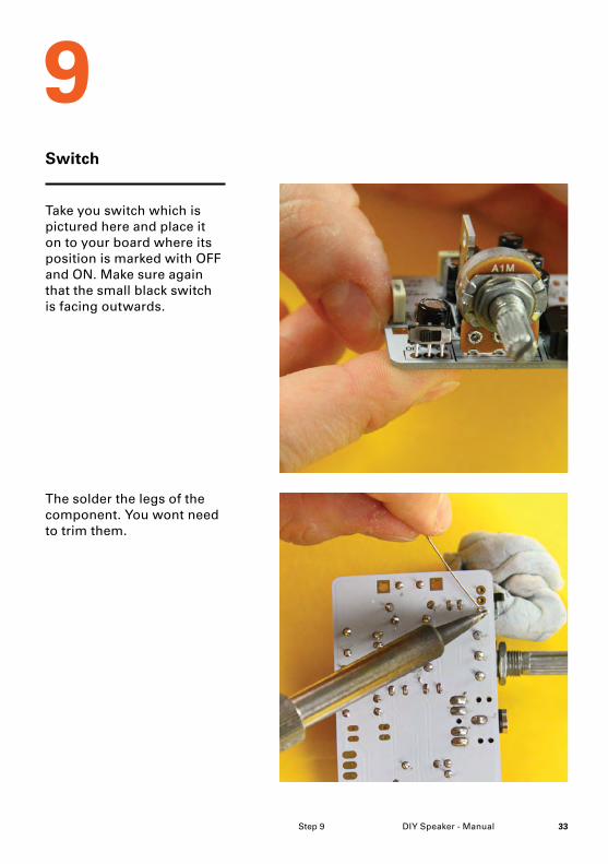
Switch
The solder the legs of the component. You wont need to trim them.
Take you switch which is pictured here and place it on to your board where its position is marked with OFF and ON. Make sure again that the small black switch is facing outwards.
9
Step 9
DIY Speaker - Manual34 Step 10
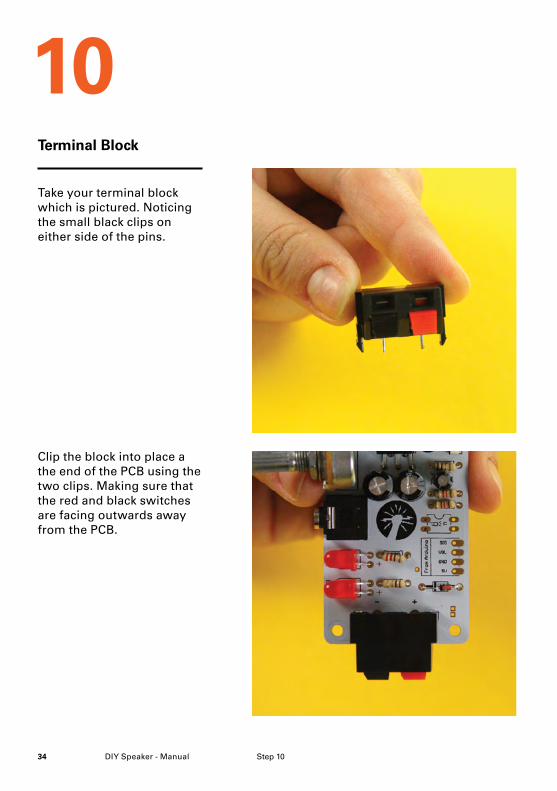
Terminal Block
Clip the block into place a the end of the PCB using the two clips. Making sure that the red and black switches are facing outwards away from the PCB.
Take your terminal block which is pictured. Noticing the small black clips on either side of the pins.
10
35DIY Speaker - Manual
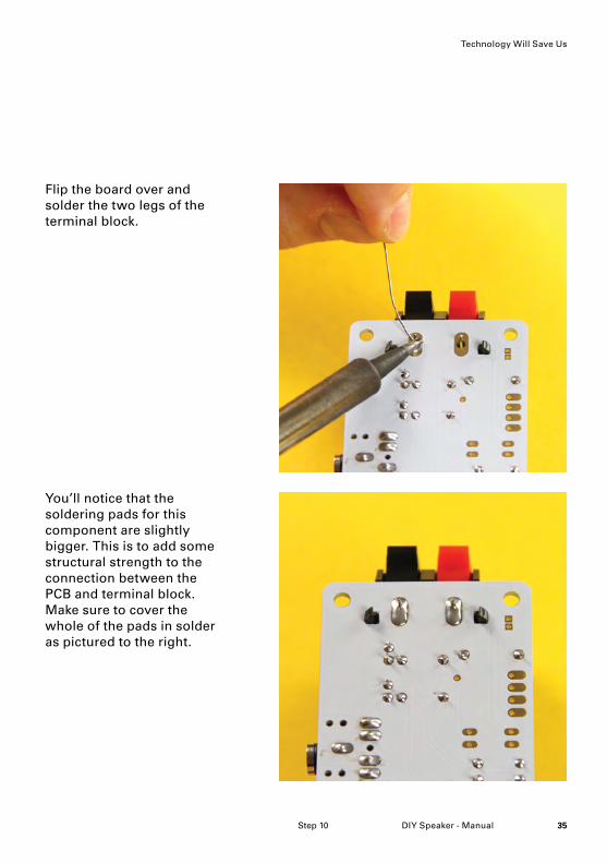
You’ll notice that the soldering pads for this component are slightly bigger. This is to add some structural strength to the connection between the PCB and terminal block. Make sure to cover the whole of the pads in solder as pictured to the right.
Flip the board over and solder the two legs of the terminal block.
Step 10
Technology Will Save Us
DIY Speaker - Manual36 Step 11
Optocoupler
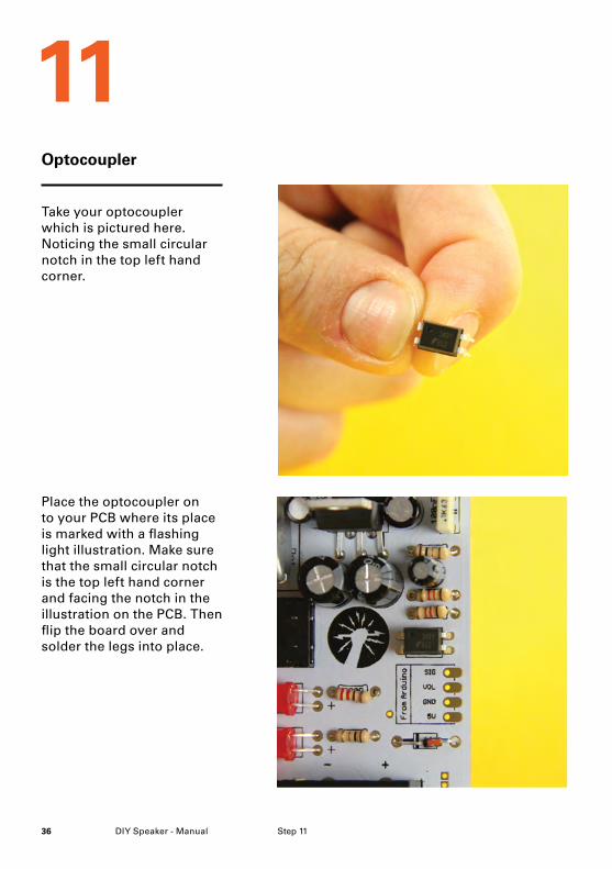
Place the optocoupler on to your PCB where its place is marked with a flashing light illustration. Make sure that the small circular notch is the top left hand corner and facing the notch in the illustration on the PCB. Then flip the board over and solder the legs into place.
Take your optocoupler which is pictured here. Noticing the small circular notch in the top left hand corner.
11
37DIY Speaker - Manual
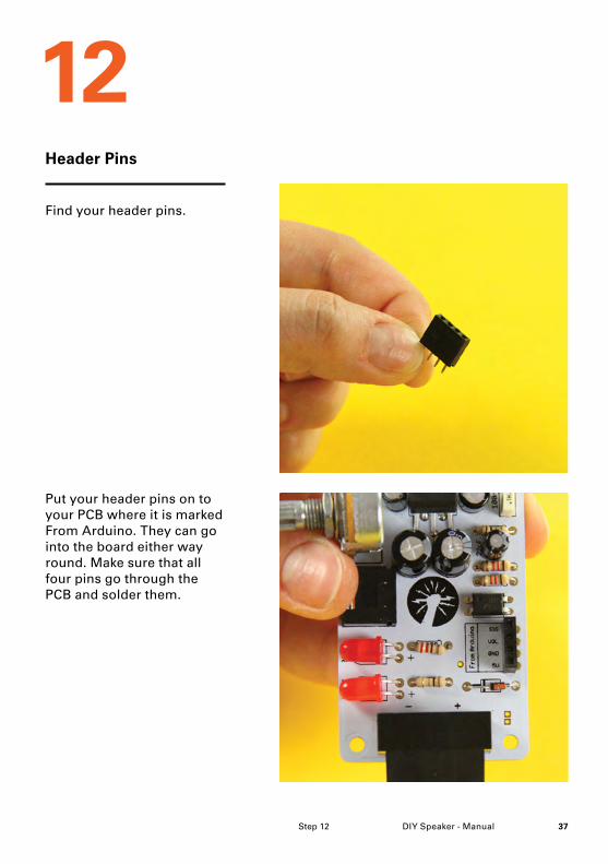
Header Pins
Put your header pins on to your PCB where it is marked From Arduino. They can go into the board either way round. Make sure that all four pins go through the PCB and solder them.
Find your header pins.
12
Step 12
DIY Speaker - Manual38
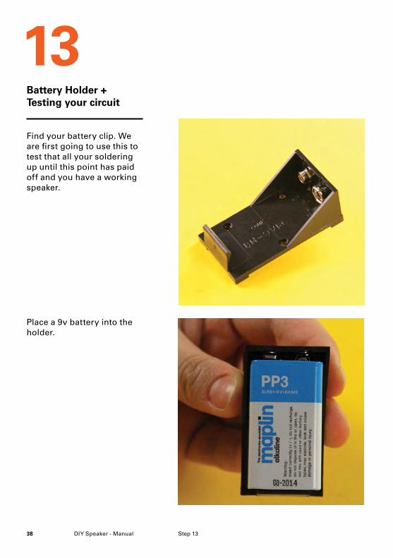
Battery Holder + Testing your circuit
Place a 9v battery into the holder.
Find your battery clip. We are first going to use this to test that all your soldering up until this point has paid off and you have a working speaker.
13
Step 13
39DIY Speaker - Manual
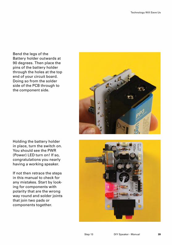
Holding the battery holder in place, turn the switch on. You should see the PWR (Power) LED turn on! If so, congratulations you nearly having a working speaker.
If not then retrace the steps in this manual to check for any mistakes. Start by look-ing for components with polarity that are the wrong way round and solder joints that join two pads or components together.
Bend the legs of the Battery holder outwards at 90 degrees. Then place the pins of the battery holder through the holes at the top end of your circuit board. Doing so from the solder side of the PCB through to the component side.
Step 13
Technology Will Save Us
DIY Speaker - Manual40
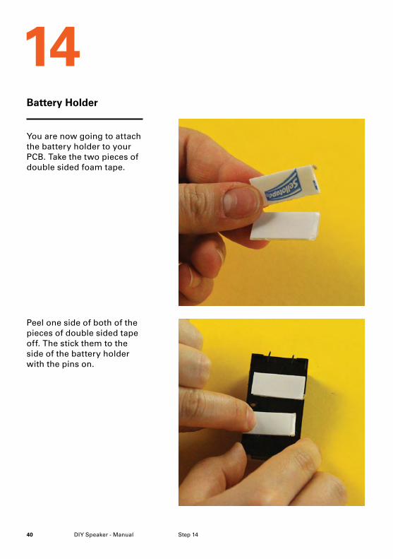
Peel one side of both of the pieces of double sided tape off. The stick them to the side of the battery holder with the pins on.
You are now going to attach the battery holder to your PCB. Take the two pieces of double sided foam tape.
Battery Holder
14
Step 14
41DIY Speaker - Manual
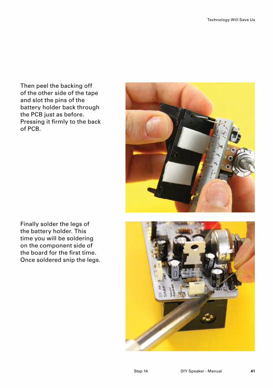
Finally solder the legs of the battery holder. This time you will be soldering on the component side of the board for the first time. Once soldered snip the legs.
Then peel the backing off of the other side of the tape and slot the pins of the battery holder back through the PCB just as before. Pressing it firmly to the back of PCB.
Technology Will Save Us
Step 14
DIY Speaker - Manual42
Exciter
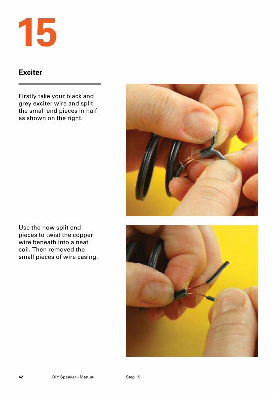
Use the now split end pieces to twist the copper wire beneath into a neat coil. Then removed the small pieces of wire casing.
Firstly take your black and grey exciter wire and split the small end pieces in half as shown on the right.
15
Step 15
43DIY Speaker - Manual
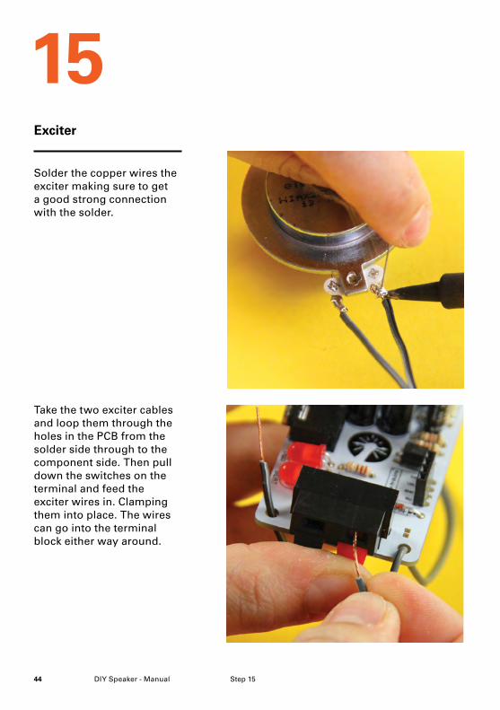
Take your silver exciter which can be seen here and feed the two copper wires through the holes at the edge of the exciter. Loop them around the hole to keep them in place ready to solder.
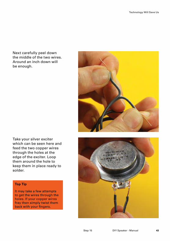
Next carefully peel down the middle of the two wires. Around an inch down will be enough.
Top Tip
It may take a few attempts to get the wires through the holes. If your copper wires fray then simply twist them back with your fingers.
Technology Will Save Us
Step 15
DIY Speaker - Manual44
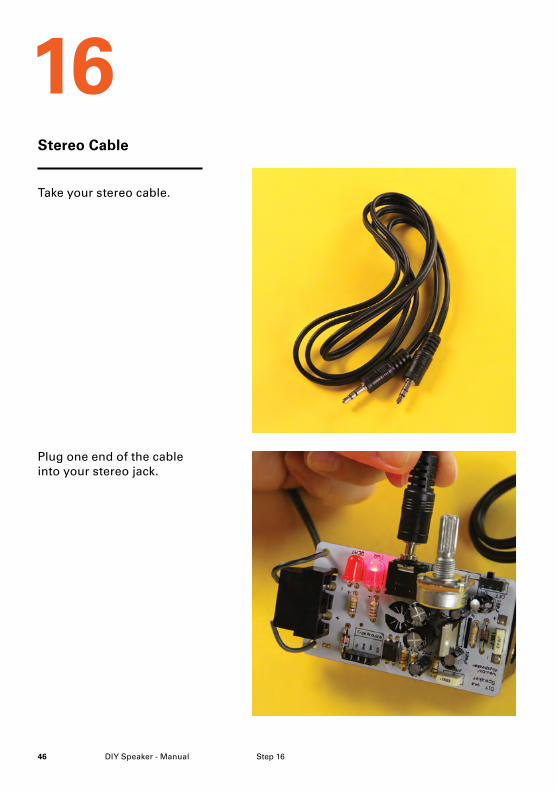
Take the two exciter cables and loop them through the holes in the PCB from the solder side through to the component side. Then pull down the switches on the terminal and feed the exciter wires in. Clamping them into place. The wires can go into the terminal block either way around.
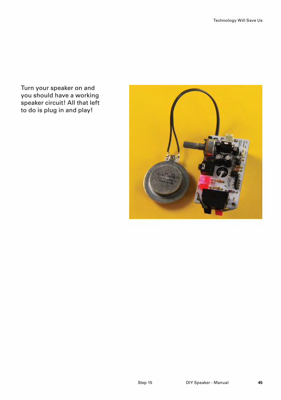
Solder the copper wires the exciter making sure to get a good strong connection with the solder.
Exciter
15
Step 15
45DIY Speaker - Manual
Turn your speaker on and you should have a working speaker circuit! All that left to do is plug in and play!
Technology Will Save Us
Step 15
DIY Speaker - Manual46 Step 16
Stereo Cable
Plug one end of the cable into your stereo jack.
Take your stereo cable.
16
47DIY Speaker - Manual
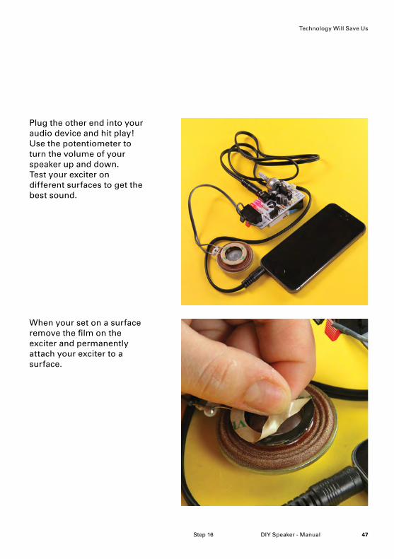
Plug the other end into your audio device and hit play! Use the potentiometer to turn the volume of your speaker up and down. Test your exciter on different surfaces to get the best sound.
When your set on a surface remove the film on the exciter and permanently attach your exciter to a surface.
Step 16
Technology Will Save Us
DIY Speaker - Manual48
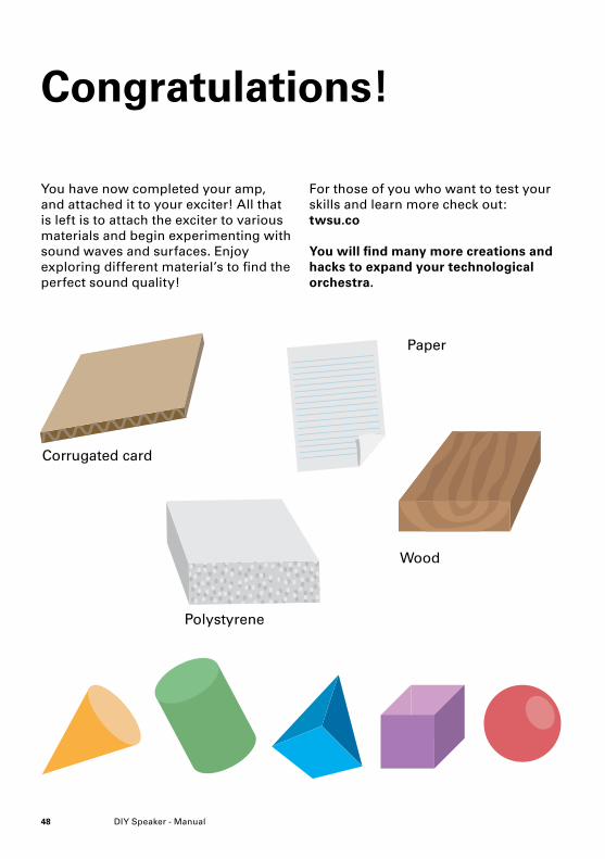
Congratulations!
You have now completed your amp, and attached it to your exciter! All that is left is to attach the exciter to various materials and begin experimenting with sound waves and surfaces. Enjoy exploring different material’s to find the perfect sound quality!
For those of you who want to test your skills and learn more check out:twsu.co
You will find many more creations and hacks to expand your technological orchestra.
Corrugated card
Paper
Polystyrene
Wood
49DIY Speaker - Manual
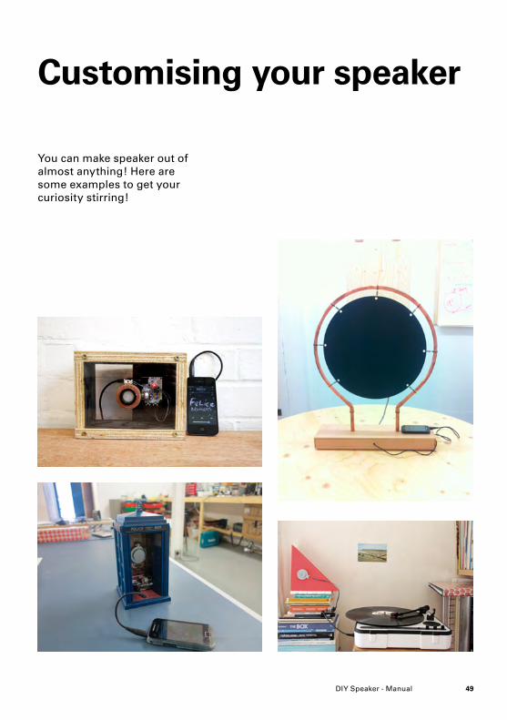
Customising your speaker
You can make speaker out of almost anything! Here are some examples to get your curiosity stirring!
DIY Speaker - Manual50
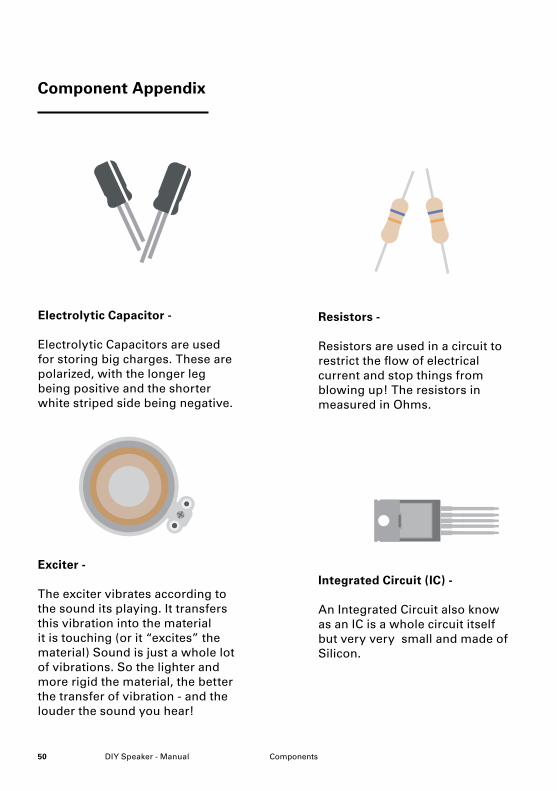
Component Appendix
Integrated Circuit (IC) -
An Integrated Circuit also know as an IC is a whole circuit itself but very very small and made of Silicon.
Resistors -
Resistors are used in a circuit to restrict the flow of electrical current and stop things from blowing up! The resistors in measured in Ohms.
Electrolytic Capacitor -
Electrolytic Capacitors are used for storing big charges. These are polarized, with the longer leg being positive and the shorter white striped side being negative.
Exciter -
The exciter vibrates according to the sound its playing. It transfers this vibration into the material it is touching (or it “excites” the material) Sound is just a whole lot of vibrations. So the lighter and more rigid the material, the better the transfer of vibration - and the louder the sound you hear!
Components
51DIY Speaker - Manual
Technology Will Save Us
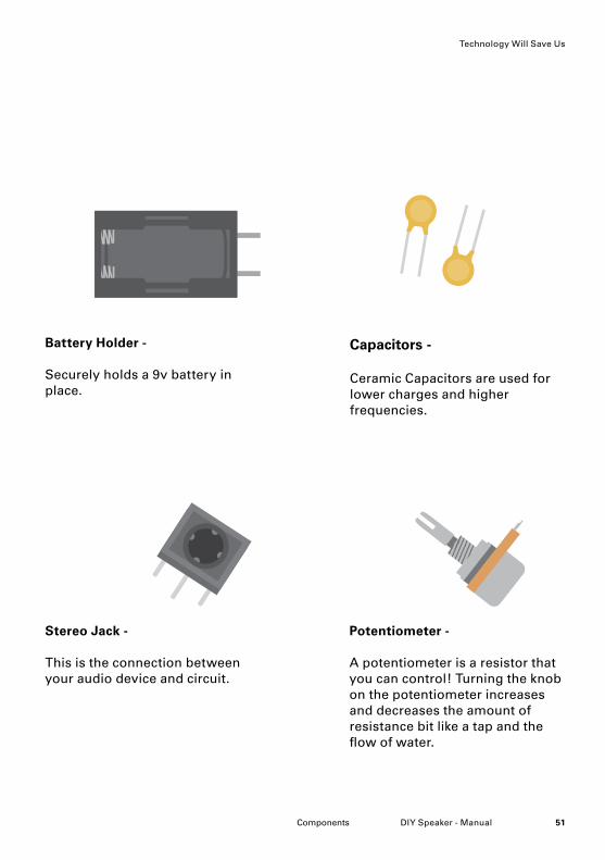
Capacitors -
Ceramic Capacitors are used for lower charges and higher frequencies.
Battery Holder -
Securely holds a 9v battery in place.
Potentiometer -
A potentiometer is a resistor that you can control! Turning the knob on the potentiometer increases and decreases the amount of resistance bit like a tap and the flow of water.
Stereo Jack -
This is the connection between your audio device and circuit.
Components
DIY Speaker - Manual52
Component Appendix
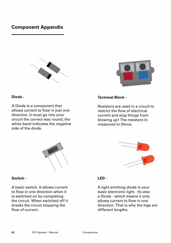
LED -
A light-emitting diode is your basic electronic light. Its also a Diode - which means it only allows current to flow in one direction. That is why the legs are different lengths.
Terminal Block -
Resistors are used in a circuit to restrict the flow of electrical current and stop things from blowing up! The resistors in measured in Ohms.
Switch -
A basic switch. It allows current to flow in one direction when it is switched on by completing the circuit. When switched off it breaks the circuit stopping the flow of current.
Components
Diode -
A Diode is a component that allows current to flow in just one direction. It must go into your circuit the correct way round, the white band indicates the negative side of the diode.
53DIY Speaker - Manual
Technology Will Save Us
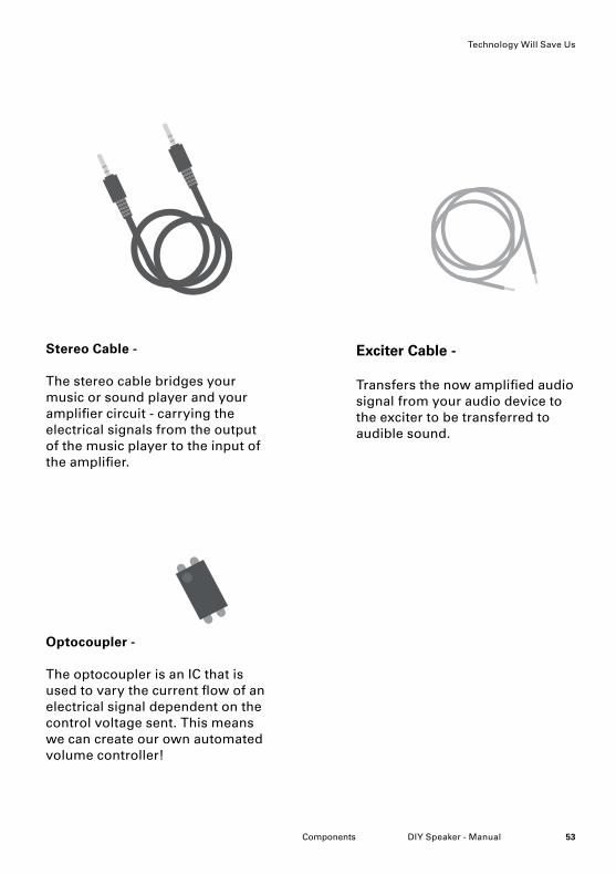
Exciter Cable -
Transfers the now amplified audio signal from your audio device to the exciter to be transferred to audible sound.
Stereo Cable -
The stereo cable bridges your music or sound player and your amplifier circuit - carrying the electrical signals from the output of the music player to the input of the amplifier.
Optocoupler -
The optocoupler is an IC that is used to vary the current flow of an electrical signal dependent on the control voltage sent. This means we can create our own automated volume controller!
Components

DIY Speaker - Manual54
Technology Will Save Us exists to educate and inspire people to make, tinker and experiment creatively with technology as a way of unleashing new possibilities.
Devices, gadgets and computers are all a part of our everyday lives and yet most people know so little about what these things are made of, let alone how to fix them or create new uses for them. We believe that the opportunity for technology to play a richer, more creative role in our lives has yet to be explored.
Thank You!

Interested in more classes? Have an idea for a workshop we should teach? Do you want to teach a class yourself? We’d love to hear from you. Contact us by email or find out more on our website. [email protected] www.techwillsaveus.com @techwillsaveus
Contact