division 3 concrete - prime construction group, inc. · e. submit laboratory test reports for...
TRANSCRIPT
DIVISION 3
CONCRETE

03300-1
SECTION 03300
CAST-IN-PLACE CONCRETE
PART 1 - GENERAL
1.1 RELATED DOCUMENTS
A. Drawings and general provisions of the Contract, including General and Supplementary Conditions and Division 01 Specification Sections, apply to this Section.
1.2 SUMMARY
A. Section includes cast-in-place concrete, including formwork, reinforcement, concrete materials, mixture design, placement procedures, and finishes, for the following:
1. Footings. 2. Foundation walls. 3. Slabs-on-grade. 4. Suspended slabs. 5. Concrete toppings. 6. Building frame members. 7. Building walls.
B. Related Sections:
1. Section 02200 "Earthwork" for drainage fill under slabs-on-grade.
1.3 DEFINITIONS
A. Cementitious Materials: Portland cement alone or in combination with one or more of the following: blended hydraulic cement, fly ash and other pozzolans, ground granulated blast-furnace slag, and silica fume; subject to compliance with requirements.
1.4 ACTION SUBMITTALS
A. Product Data: For each type of product indicated.
B. Design Mixtures: For each concrete mixture. Submit alternate design mixtures when characteristics of materials, Project conditions, weather, test results, or other circumstances warrant adjustments.
1. Indicate amounts of mixing water to be withheld for later addition at Project site. 2. Water/cement ratio (total gallons of water per cubic yard). 3. Brand, type, and quantity of cement. 4. Type and quantity of aggregates. 5. Type and quantity of admixtures.
03300-2
6. Type, composition, and quantity of fly ash, slag (GGBFS), or silica fume. 7. Unit weight (wet density). 8. Composition strength based on 28-day compression test.
C. Steel Reinforcement Shop Drawings: Placing drawings that detail fabrication, bending, and placement. Include bar sizes, lengths, material, grade, bar schedules, stirrup spacing, bent bar diagrams, bar arrangement, splices and laps, mechanical connections, tie spacing, hoop spacing, and supports for concrete reinforcement.
D. Formwork Shop Drawings: Prepared by or under the supervision of a qualified professional engineer detailing fabrication, assembly, and support of formwork.
1. Shoring and Reshoring: Indicate proposed schedule and sequence of stripping formwork, shoring removal, and reshoring installation and removal.
E. Construction Joint Layout: Indicate proposed construction joints required to construct the structure.
1. Location of construction joints is subject to approval of the Engineer.
F. Samples: For waterstops vapor retarder.
1.5 INFORMATIONAL SUBMITTALS
A. Qualification Data: For Installer manufacturer testing agency.
B. Welding certificates.
C. Material Certificates: For each of the following, signed by manufacturers:
1. Cementitious materials. 2. Admixtures. 3. Form materials and form-release agents. 4. Steel reinforcement and accessories. 5. Fiber reinforcement. 6. Waterstops. 7. Curing compounds. 8. Floor and slab treatments. 9. Bonding agents. 10. Adhesives. 11. Vapor retarders. 12. Joint-filler strips. 13. Repair materials.
D. Material Test Reports: For the following, from a qualified testing agency, indicating compliance with requirements:
03300-3
1. Aggregates. Include service record data indicating absence of deleterious expansion of concrete due to alkali aggregate reactivity.
E. Submit laboratory test reports for concrete mix design, aggregates (particularly deleterious materials in coarse aggregate) and fly ash, slag (GGBFS) and silica fume (if used) 4 weeks before scheduled pouring.
1. For mass concrete, submit laboratory test report on the heat of hydration for the
trial mix design if requested by ENGINEER. Trial mix design shall consist of concrete block 4-foot by 4-foot by 4-foot.
F. Floor surface flatness and levelness measurements indicating compliance with specified tolerances.
G. Field quality-control reports.
1. Submit written reports to ENGINEER documenting testing and inspection results. Prepare report as noted in Section 01410.
2. Submit mill test reports on reinforcement. 3. Submit materials certificates in lieu of laboratory test reports on other materials.
Manufacturer and CONTRACTOR shall sign material certificates certifying that each material item complies with, or exceeds, specified requirements. Submit certification from admixture manufacturers that chloride content complies with specification requirements.
H. Minutes of preinstallation conference.
1.6 QUALITY ASSURANCE
A. Installer Qualifications: A qualified installer who employs on Project personnel qualified as ACI-certified Flatwork Technician and Finisher and a supervisor who is an ACI-certified Concrete Flatwork Technician.
B. Manufacturer Qualifications: A firm experienced in manufacturing ready-mixed concrete products and that complies with ASTM C 94/C 94M requirements for production facilities and equipment.
1. Manufacturer certified according to NRMCA's "Certification of Ready Mixed Concrete Production Facilities."
C. Testing Agency Qualifications: An independent agency, acceptable to authorities having jurisdiction, qualified according to ASTM C 1077 and ASTM E 329 for testing indicated.
1. Personnel conducting field tests shall be qualified as ACI Concrete Field Testing Technician, Grade 1, according to ACI CP-1 or an equivalent certification program.
03300-4
2. Personnel performing laboratory tests shall be ACI-certified Concrete Strength Testing Technician and Concrete Laboratory Testing Technician - Grade I. Testing Agency laboratory supervisor shall be an ACI-certified Concrete Laboratory Testing Technician - Grade II.
D. Source Limitations: Obtain each type or class of cementitious material of the same brand from the same manufacturer's plant, obtain aggregate from single source, and obtain admixtures from single source from single manufacturer.
E. Welding Qualifications: Qualify procedures and personnel according to AWS D1.4/D 1.4M, "Structural Welding Code - Reinforcing Steel."
F. ACI Publications: Comply with the following unless modified by requirements in the Contract Documents:
1. ACI 301, "Specifications for Structural Concrete," Sections 1 through 5. 2. ACI 117, "Specifications for Tolerances for Concrete Construction and
Materials."
G. Concrete Testing Service: Engage a qualified independent testing agency to perform material evaluation tests and to design concrete mixtures.
H. Mockups: Cast concrete slab-on-grade panels to demonstrate typical joints, surface finish, texture, tolerances, floor treatments, and standard of workmanship.
1. Build panel approximately 200 sq. ft. (18.6 sq. m) for slab-on-grade in the location indicated or, if not indicated, as directed by Engineer.
2. Approved mockups may become part of the completed Work if undisturbed at time of Substantial Completion.
I. Preinstallation Conference: Conduct conference at Project site.
1. Before submitting design mixtures, review concrete design mixture and examine procedures for ensuring quality of concrete materials. Require representatives of each entity directly concerned with cast-in-place concrete to attend, including the following:
a. Contractor's superintendent. b. Independent testing agency responsible for concrete design mixtures. c. Ready-mix concrete manufacturer. d. Concrete subcontractor. e. Special concrete finish subcontractor.
2. Review special inspection and testing and inspecting agency procedures for field quality control, concrete finishes and finishing, cold- and hot-weather concreting procedures, curing procedures, construction contraction and isolation joints, and joint-filler strips, semirigid joint fillers, forms and form removal limitations, vapor-retarder installation, anchor rod and anchorage device installation
03300-5
tolerances, steel reinforcement installation, floor and slab flatness and levelness measurement, concrete repair procedures, and concrete protection.
1.7 DELIVERY, STORAGE, AND HANDLING
A. Steel Reinforcement: Deliver, store, and handle steel reinforcement to prevent bending and damage.
B. Waterstops: Store waterstops under cover to protect from moisture, sunlight, dirt, oil, and other contaminants.
1.8 PROJECT CONDITIONS
A. Protect adjacent finish materials against spatter during concrete placement.
PART 2 - PRODUCTS
2.1 FORM-FACING MATERIALS
A. Smooth-Formed Finished Concrete: Form-facing panels that will provide continuous, true, and smooth concrete surfaces. Furnish in largest practicable sizes to minimize number of joints.
1. Plywood, metal, or other approved panel materials. 2. Exterior-grade plywood panels, suitable for concrete forms, complying with
DOC PS 1, and as follows:
a. High-density overlay, Class 1 or better. b. Medium-density overlay, Class 1 or better; mill-release agent treated and
edge sealed. c. Structural 1, B-B or better; mill oiled and edge sealed. d. B-B (Concrete Form), Class 1 or better; mill oiled and edge sealed.
B. Rough-Formed Finished Concrete: Plywood, lumber, metal, or another approved material. Provide lumber dressed on at least two edges and one side for tight fit.
C. Forms for Cylindrical Columns, Pedestals, and Supports: Metal, glass-fiber-reinforced plastic, paper, or fiber tubes that will produce surfaces with gradual or abrupt irregularities not exceeding specified formwork surface class. Provide units with sufficient wall thickness to resist plastic concrete loads without detrimental deformation.
D. Chamfer Strips: Wood, metal, PVC, or rubber strips, 3/4 by 3/4 inch (19 by 19 mm), minimum.
E. Rustication Strips: Wood, metal, PVC, or rubber strips, kerfed for ease of form removal.
03300-6
F. Form-Release Agent: Commercially formulated form-release agent that will not bond with, stain, or adversely affect concrete surfaces and will not impair subsequent treatments of concrete surfaces.
1. Formulate form-release agent with rust inhibitor for steel form-facing materials.
G. Form Ties: Factory-fabricated, removable or snap-off metal or glass-fiber-reinforced plastic form ties designed to resist lateral pressure of fresh concrete on forms and to prevent spalling of concrete on removal.
1. Furnish units that will leave no corrodible metal closer than 1 inch (25 mm) to the plane of exposed concrete surface.
2. Furnish ties with integral water-barrier plates to walls indicated to receive dampproofing or waterproofing.
2.2 STEEL REINFORCEMENT
A. Reinforcing Bars: ASTM A 615/A 615M, Grade 60 (Grade 420), deformed.
B. Plain-Steel Wire: ASTM A 82/A 82M, as drawn.
C. Deformed-Steel Wire: ASTM A 496/A 496M.
D. Plain-Steel Welded Wire Reinforcement: ASTM A 185/A 185M, plain, fabricated from as-drawn steel wire into flat sheets.
2.3 REINFORCEMENT ACCESSORIES
A. Joint Dowel Bars: ASTM A 615/A 615M, Grade 60 (Grade 420), plain-steel bars, cut true to length with ends square and free of burrs.
B. Bar Supports: Bolsters, chairs, spacers, and other devices for spacing, supporting, and fastening reinforcing bars and welded wire reinforcement in place. Manufacture bar supports from steel wire, plastic, or precast concrete according to CRSI's "Manual of Standard Practice," of greater compressive strength than concrete and as follows:
1. For concrete surfaces exposed to view where legs of wire bar supports contact forms, use CRSI Class 1 plastic-protected steel wire or CRSI Class 2 stainless-steel bar supports.
2.4 CONCRETE MATERIALS
A. Cementitious Material: Use the following cementitious materials, of the same type, brand, and source, throughout Project:
1. Portland Cement: ASTM C 150, Type I, except use Type III where applications
require high-early-strength or Type II where required by ENGINEER for corro-sive environments.
03300-7
2. Use one brand of cement throughout Project, unless otherwise acceptable to ENGINEER.
B. Fly Ash: ASTM C 618, Type C or Type F (corrosive environments) with loss on ignition not more than 6 percent.
C. Ground Granulated Blast-Furnace Slag: ASTM C 989.
D. Silica Fume: ASTM C 1240, amorphous silica.
E. Normal-Weight Aggregates: ASTM C 33, Class 3M coarse aggregate or better, graded. Provide aggregates from a single source with documented service record data of at least 10 years' satisfactory service in similar applications and service conditions using similar aggregates and cementitious materials.
1. Maximum Coarse-Aggregate Size: 1-1/2 inches (38 mm) nominal. 2. Fine Aggregate: Free of materials with deleterious reactivity to alkali in cement.
F. Water: ASTM C 94/C 94M.
G. Potable Water Structures: For surfaces in contact with potable water, use only materials approved by Department of Public Health of the state that has jurisdiction.
2.5 ADMIXTURES
A. Air-Entraining Admixture: ASTM C 260.
B. Chemical Admixtures: Provide admixtures certified by manufacturer to be compatible with other admixtures and that will not contribute water-soluble chloride ions exceeding those permitted in hardened concrete. Do not use calcium chloride or admixtures containing calcium chloride.
1. Prohibited Admixtures: Calcium chloride thyocyanates or admixtures containing
more than 0.1 percent chloride ions. 2. Water-Reducing Admixture: ASTM C 494/C 494M, Type A. 3. Water-Reducing and Retarding Admixture: ASTM C 494/C 494M, Type D. 4. High-Range, Water-Reducing Admixture: ASTM C 494/C 494M, Type F. 5. Water Reducing, Nonchloride Accelerator Admixture: ASTM C 494, Type E. 6. High-Range, Water-Reducing and Retarding Admixture: ASTM C 494/C 494M,
Type G.
2.6 FIBER REINFORCEMENT
A. Synthetic Micro-Fiber: Monofilament polypropylene micro-fibers engineered and designed for use in concrete, complying with ASTM C 1116/C 1116M, Type III, 1 to 2-1/4 inches (25 to 57 mm) long.
03300-8
1. Products: Subject to compliance with requirements, available products that may be incorporated into the Work include, but are not limited to, the following:
a. Monofilament Micro-Fibers:
1) Axim Italcementi Group, Inc.; Fibrasol II P. 2) Euclid Chemical Company (The), an RPM company; Fiberstrand
150. 3) FORTA Corporation; FORTA Econo-Mono. 4) Grace Construction Products, W. R. Grace & Co.; Grace MicroFiber. 5) Metalcrete Industries; Polystrand 1000. 6) Nycon, Inc.; ProConM. 7) Propex Concrete Systems Corp.; Fibermesh 150. 8) Sika Corporation; Sika Fiber PPM.
2.7 WATERSTOPS
A. Chemically Resistant Flexible Waterstops: Thermoplastic elastomer rubber waterstops with factory-installed metal eyelets, for embedding in concrete to prevent passage of fluids through joints; resistant to oils, solvents, and chemicals. Factory fabricate corners, intersections, and directional changes.
1. JP Specialties, Inc. 2. Sika Corporation 3. Vinylex Waterstop & Accessories 4. Westec Barrier Technologies 5. Profile: As indicated. 6. Dimensions: as indicated on the structural drawings.
B. Flexible PVC Waterstops: CE CRD-C 572, for embedding in concrete to prevent passage of fluids through joints. Factory fabricate corners, intersections, and directional changes.
1. BoMetals, Inc 2. Paul Murphy Plastics Company 3. Sika Corporation 4. Vinylex Waterstop & Accessories 5. Profile: as indicated on the structural drawings. 6. Dimensions: as indicated on the structural drawings.
C. Self-Expanding Butyl Strip Waterstops: Manufactured rectangular or trapezoidal strip, butyl rubber with sodium bentonite or other hydrophilic polymers, for adhesive bonding to concrete, 3/4 by 1 inch (19 by 25 mm).
1. Carlisle Coatings & Waterstop 2. CETCO 3. Concrete Sealants Inc. 4. Henry Company, Sealants Division
03300-9
5. JP Specialties, Inc. 6. Sika Corporation
D. Self-Expanding Rubber Strip Waterstops: Manufactured rectangular or trapezoidal strip, bentonite-free hydrophilic polymer modified chloroprene rubber, for adhesive bonding to concrete, 3/8 by 3/4 inch (10 by 19 mm).
1. Adeka Ultra Seal/OCM, Inc. 2. Sika Corporation 3. Vinylex Waterstop & Accesories
2.8 VAPOR RETARDERS
A. Sheet Vapor Retarder: ASTM E 1745, Class B. Include manufacturer's recommended adhesive or pressure-sensitive tape.
1. Fortifiber Building System 2. Raven Industries, Inc. 3. Stego Industries, LLC
B. Sheet Vapor Retarder: Polyethylene sheet, ASTM D 4397, not less than 10 mils (0.25 mm) thick.
2.9 FLOOR AND SLAB TREATMENTS: Refer to specification 09907, Protective Concrete Coatings.
2.10 CURING MATERIALS
A. Absorptive Cover: AASHTO M 182, Class 2, burlap cloth made from jute or kenaf, weighing approximately 9 oz./sq. yd. (305 g/sq. m) when dry.
B. Moisture-Retaining Cover: ASTM C 171, polyethylene film or white burlap-polyethylene sheet.
C. Water: Potable.
D. Clear, Waterborne, Membrane-Forming Curing Compound: ASTM C 309, Type 1, Class B, nondissipating, certified by curing compound manufacturer to not interfere with bonding of floor covering.
1. BASF Construction Chemical 2. ChemMasters, Inc. 3. Dayton Superior 4. Euclid Chemical Company 5. Kaufman Products, Inc. 6. L&M Construction Chemical 7. Lambert Corporation 8. Metalcrete Industries
03300-10
9. Nox-Crete Products Group 10. Sika Corporation 11. SpecChem 12. Symons by Dayton Superior 13. TK Products Unitex by Dayton Superior 14. Vexcon Chemicals Inc. 15. W.R. Meadows, Inc.
2.11 RELATED MATERIALS
A. Expansion- and Isolation-Joint-Filler Strips: ASTM D 1751, asphalt-saturated cellulosic fiber or ASTM D 1752, cork or self-expanding cork.
B. Reglets: Fabricate reglets of not less than 0.022-inch- (0.55-mm-) thick, galvanized-steel sheet. Temporarily fill or cover face opening of reglet to prevent intrusion of concrete or debris.
C. Dovetail Anchor Slots: Hot-dip galvanized-steel sheet, not less than 0.034 inch (0.85 mm) thick, with bent tab anchors. Temporarily fill or cover face opening of slots to prevent intrusion of concrete or debris.
2.12 REPAIR MATERIALS
A. Repair Underlayment: Cement-based, polymer-modified, self-leveling product that can be applied in thicknesses from 1/8 inch (3.2 mm) and that can be feathered at edges to match adjacent floor elevations.
1. Cement Binder: ASTM C 150, portland cement or hydraulic or blended hydraulic cement as defined in ASTM C 219.
2. Primer: Product of underlayment manufacturer recommended for substrate, conditions, and application.
3. Aggregate: Well-graded, washed gravel, 1/8 to 1/4 inch (3.2 to 6 mm) or coarse sand as recommended by underlayment manufacturer.
4. Compressive Strength: Not less than 4000 psi (29 MPa) at 28 days when tested according to ASTM C 109/C 109M.
B. Repair Overlayment: Cement-based, polymer-modified, self-leveling product that can be applied in thicknesses from 1/4 inch (6.4 mm) and that can be filled in over a scarified surface to match adjacent floor elevations.
1. Cement Binder: ASTM C 150, portland cement or hydraulic or blended hydraulic cement as defined in ASTM C 219.
2. Primer: Product of topping manufacturer recommended for substrate, conditions, and application.
3. Aggregate: Well-graded, washed gravel, 1/8 to 1/4 inch (3.2 to 6 mm) or coarse sand as recommended by topping manufacturer.
4. Compressive Strength: Not less than 5000 psi (34.5 MPa) at 28 days when tested according to ASTM C 109/C 109M.
03300-11
2.13 CONCRETE MIXTURES, GENERAL
A. Prepare design mixes for each concrete class and strength by either laboratory trial batch or field experience methods as specified in ACI 301. If trial batch method is used, use independent testing facilities acceptable to ENGINEER for preparing and reporting proposed mix designs. Testing facility shall not be identical to that used for field quality control testing.
B. Fly ash shall be used to partially supplant cement content in Class A and Class S concrete, unless noted otherwise, and is optional in other classes. Replacement quantity of cement content by weight shall be not less than 15 percent for Class A and Class S concrete or more than 25 percent for all classes except Class F.
C. For concrete Class A and Class S, concrete mix design with fly ash and silica fume shall be maximum 30 percent of cement content by weight, and shall constitute no more than 20 and 10 percent, respectively, of the total weight of cementitious materials.
D. For concrete, Class S, use Portland cement Type II with fly ash, Type F.
E. Ground granulated blast furnace slag (GGBFS) shall only be permitted for mass concrete placement and as approved by ENGINEER. Replacement quantity of cement content weight shall not be less than 35 percent or more than 50 percent.
F. Coarse aggregate shall be 1-1/2” top size, except for Class G concrete which shall be 3/8” top size.
G. Design mixes to provide normal weight concrete for following classes and properties:
1. Locations for concrete classes are as follows:
a. Class A Structural concrete (slabs, walls, columns, beams, equipment bases, and slab toppings 2 inches or greater in thickness).
b. Class S Sulfate resistant structural concrete (slabs, walls, columns, and beams) where indicated on Drawings.
c. Class G Grout fill for use in sweeping in final surfaces in sanitary structures and slab toppings less than 2 inches in thickness.
d. Class P Exterior pavements (unless otherwise indicated on Drawings). e. Class B Sidewalks and manhole bases (unless otherwise indicated on
Drawings). f. Class C Fill within manholes, mud mats, fill under structures, encasement
for piping below or adjacent to structures and encasement for floor drains, sewer inlets and similar items.
g. Class F Flowable fill for filling spaces as permitted and directed by ENGINEER.
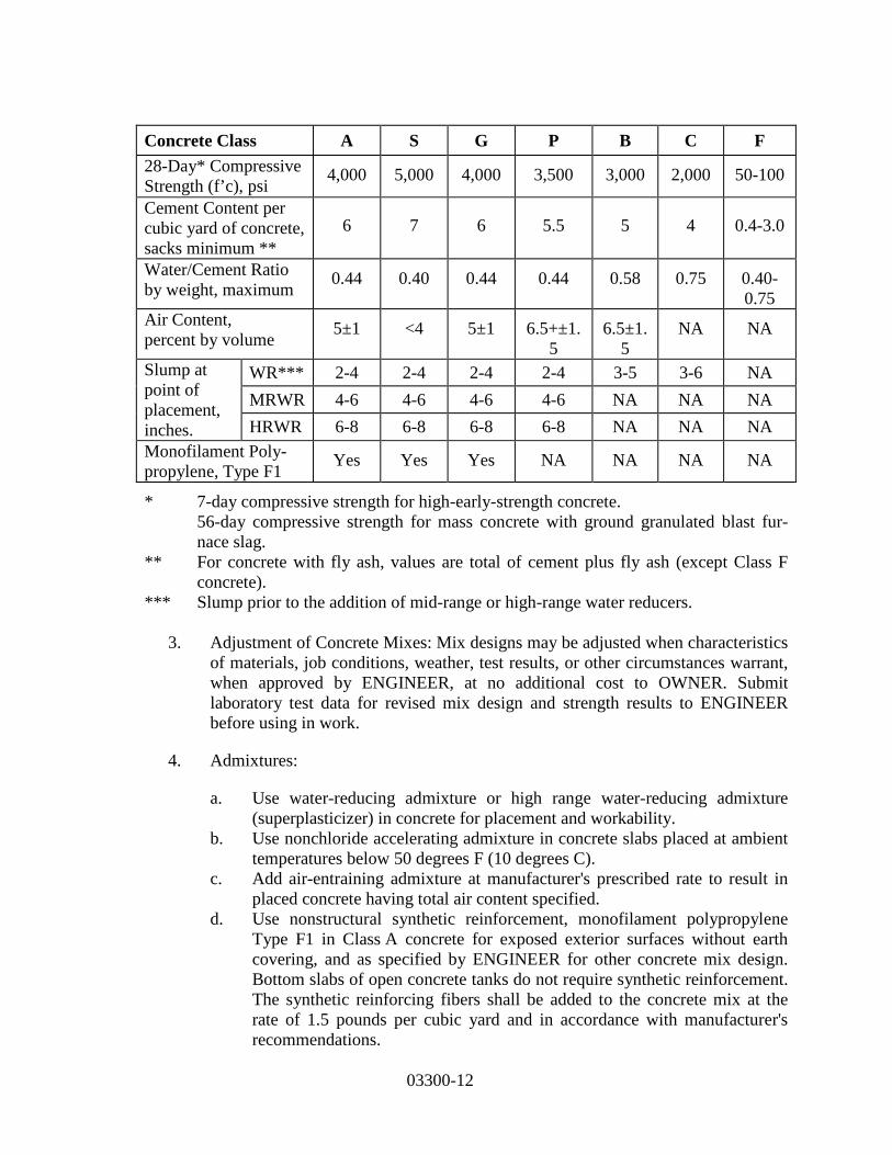
2. Properties for concrete classes are as follows:
03300-12
Concrete Class A S G P B C F 28-Day* Compressive Strength (f’c), psi 4,000 5,000 4,000 3,500 3,000 2,000 50-100
Cement Content per cubic yard of concrete, sacks minimum **
6 7 6 5.5 5 4 0.4-3.0
Water/Cement Ratio by weight, maximum 0.44 0.40 0.44 0.44 0.58 0.75 0.40-
0.75 Air Content, percent by volume 5±1 <4 5±1 6.5+±1.
5 6.5±1.
5 NA NA
Slump at point of placement, inches.
WR*** 2-4 2-4 2-4 2-4 3-5 3-6 NA MRWR 4-6 4-6 4-6 4-6 NA NA NA HRWR 6-8 6-8 6-8 6-8 NA NA NA
Monofilament Poly-propylene, Type F1 Yes Yes Yes NA NA NA NA
* 7-day compressive strength for high-early-strength concrete. 56-day compressive strength for mass concrete with ground granulated blast fur-nace slag.
** For concrete with fly ash, values are total of cement plus fly ash (except Class F concrete).
*** Slump prior to the addition of mid-range or high-range water reducers.
3. Adjustment of Concrete Mixes: Mix designs may be adjusted when characteristics of materials, job conditions, weather, test results, or other circumstances warrant, when approved by ENGINEER, at no additional cost to OWNER. Submit laboratory test data for revised mix design and strength results to ENGINEER before using in work.
4. Admixtures:
a. Use water-reducing admixture or high range water-reducing admixture (superplasticizer) in concrete for placement and workability.
b. Use nonchloride accelerating admixture in concrete slabs placed at ambient temperatures below 50 degrees F (10 degrees C).
c. Add air-entraining admixture at manufacturer's prescribed rate to result in placed concrete having total air content specified.
d. Use nonstructural synthetic reinforcement, monofilament polypropylene Type F1 in Class A concrete for exposed exterior surfaces without earth covering, and as specified by ENGINEER for other concrete mix design. Bottom slabs of open concrete tanks do not require synthetic reinforcement. The synthetic reinforcing fibers shall be added to the concrete mix at the rate of 1.5 pounds per cubic yard and in accordance with manufacturer's recommendations.
03300-13
2.14 FABRICATING REINFORCEMENT
A. Fabricate steel reinforcement according to CRSI's "Manual of Standard Practice."
2.15 CONCRETE MIXING
1. Ready-Mixed Concrete: Measure, batch, mix, and deliver concrete according to ASTM C 94/C 94M and ASTM C 1116/C 1116M, and furnish batch ticket information.
2. When air temperature is between 85 and 90 deg F (30 and 32 deg C), reduce mixing and delivery time from 1-1/2 hours to 75 minutes; when air temperature is above 90 deg F (32 deg C), reduce mixing and delivery time to 60 minutes.
PART 3 - EXECUTION
3.1 FORMWORK
A. Design, erect, shore, brace, and maintain formwork, according to ACI 301, to support vertical, lateral, static, and dynamic loads, and construction loads that might be applied, until structure can support such loads.
B. Construct formwork so concrete members and structures are of size, shape, alignment, elevation, and position indicated, within tolerance limits of ACI 117.
C. Limit concrete surface irregularities, designated by ACI 347 as abrupt or gradual, as follows:
1. Class A, 1/8 inch (3.2 mm) for smooth-formed finished surfaces. 2. Class B, 1/4 inch (6 mm) for rough-formed finished surfaces.
D. Construct forms tight enough to prevent loss of concrete mortar.
E. Fabricate forms for easy removal without hammering or prying against concrete surfaces. Provide crush or wrecking plates where stripping may damage cast concrete surfaces. Provide top forms for inclined surfaces steeper than 1.5 horizontal to 1 vertical.
1. Install keyways, reglets, recesses, and the like, for easy removal. 2. Do not use rust-stained steel form-facing material.
F. Set edge forms, bulkheads, and intermediate screed strips for slabs to achieve required elevations and slopes in finished concrete surfaces. Provide and secure units to support screed strips; use strike-off templates or compacting-type screeds.
G. Provide temporary openings for cleanouts and inspection ports where interior area of formwork is inaccessible. Close openings with panels tightly fitted to forms and
03300-14
securely braced to prevent loss of concrete mortar. Locate temporary openings in forms at inconspicuous locations.
H. Chamfer exterior corners and edges of permanently exposed concrete.
I. Form openings, chases, offsets, sinkages, keyways, reglets, blocking, screeds, and bulkheads required in the Work. Determine sizes and locations from trades providing such items.
J. Clean forms and adjacent surfaces to receive concrete. Remove chips, wood, sawdust, dirt, and other debris just before placing concrete.
K. Retighten forms and bracing before placing concrete, as required, to prevent mortar leaks and maintain proper alignment.
L. Coat contact surfaces of forms with form-release agent, according to manufacturer's written instructions, before placing reinforcement.
3.2 EMBEDDED ITEMS
A. Place and secure anchorage devices and other embedded items required for adjoining work that is attached to or supported by cast-in-place concrete. Use setting drawings, templates, diagrams, instructions, and directions furnished with items to be embedded.
1. Install anchor rods, accurately located, to elevations required and complying with tolerances in Section 7.5 of AISC's "Code of Standard Practice for Steel Buildings and Bridges."
2. Install reglets to receive waterproofing and to receive through-wall flashings in outer face of concrete frame at exterior walls, where flashing is shown at lintels, shelf angles, and other conditions.
3. Install dovetail anchor slots in concrete structures as indicated.
3.3 REMOVING AND REUSING FORMS
A. Vertical Forms not supporting concrete weight may be removed when concrete has sufficiently set to resist damage from removal operation.
B. Other forms shall be left in place until concrete has attained strength to support its own
weight and construction live loads, unless removed in sections, and each structural section immediately reshored.
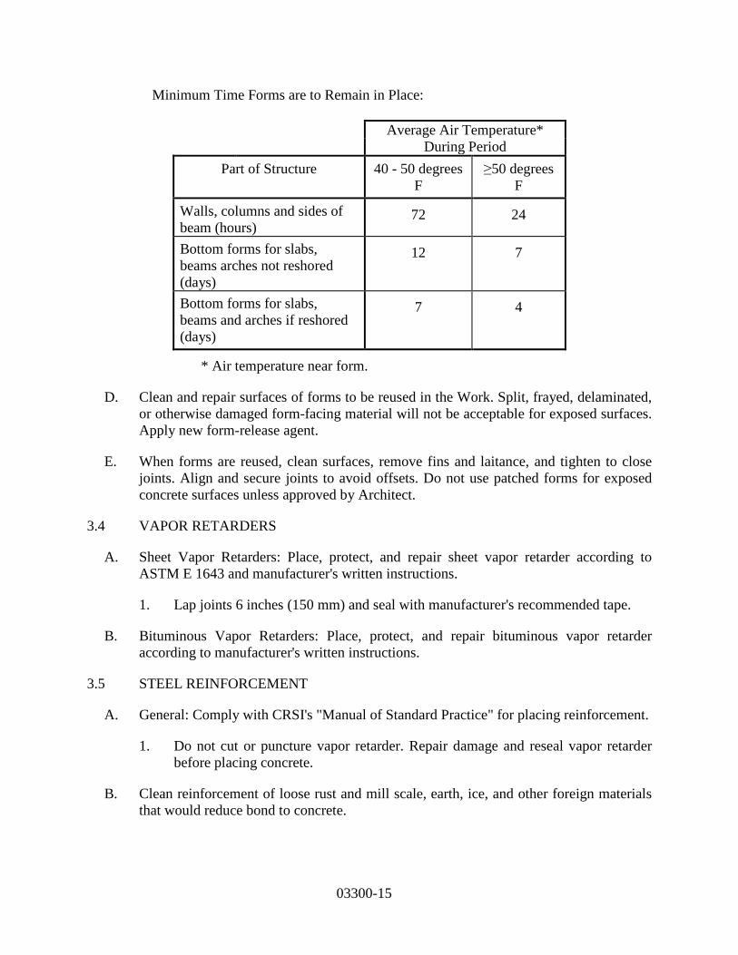
C. Time Periods: Forms remain in place as shown in table below. If form removal occurs
before time shown in the table, apply curing procedures previously specified.
03300-15
Minimum Time Forms are to Remain in Place:
Average Air Temperature* During Period
Part of Structure 40 - 50 degrees F
≥50 degrees F
Walls, columns and sides of beam (hours)
72 24
Bottom forms for slabs, beams arches not reshored (days)
12 7
Bottom forms for slabs, beams and arches if reshored (days)
7 4
* Air temperature near form.
D. Clean and repair surfaces of forms to be reused in the Work. Split, frayed, delaminated, or otherwise damaged form-facing material will not be acceptable for exposed surfaces. Apply new form-release agent.
E. When forms are reused, clean surfaces, remove fins and laitance, and tighten to close joints. Align and secure joints to avoid offsets. Do not use patched forms for exposed concrete surfaces unless approved by Architect.
3.4 VAPOR RETARDERS
A. Sheet Vapor Retarders: Place, protect, and repair sheet vapor retarder according to ASTM E 1643 and manufacturer's written instructions.
1. Lap joints 6 inches (150 mm) and seal with manufacturer's recommended tape.
B. Bituminous Vapor Retarders: Place, protect, and repair bituminous vapor retarder according to manufacturer's written instructions.
3.5 STEEL REINFORCEMENT
A. General: Comply with CRSI's "Manual of Standard Practice" for placing reinforcement.
1. Do not cut or puncture vapor retarder. Repair damage and reseal vapor retarder before placing concrete.
B. Clean reinforcement of loose rust and mill scale, earth, ice, and other foreign materials that would reduce bond to concrete.
03300-16
C. Accurately position, support, and secure reinforcement against displacement. Locate and support reinforcement with bar supports to maintain minimum concrete cover. Do not tack weld crossing reinforcing bars.
D. Set wire ties with ends directed into concrete, not toward exposed concrete surfaces.
E. Install welded wire reinforcement in longest practicable lengths on bar supports spaced to minimize sagging. Lap edges and ends of adjoining sheets at least one mesh spacing. Offset laps of adjoining sheet widths to prevent continuous laps in either direction. Lace overlaps with wire.
F. Field bending of reinforcement:
1. Field bending of plain reinforcement shall be performed using an approved and appropriate sized portable hydraulic device that makes ACI-approved radius bends. No other field bending method shall be permitted.
2. No field bending shall be permitted for epoxy coated reinforcement.
3.6 JOINTS
A. Locate and install construction joints as shown or, if not shown, locate so as not to impair strength and appearance of structures, at intervals not to exceed 50 feet. For construction joints in water-containing structures or tanks or in water-restraining structures, use watertight joints.
B. Continue reinforcement across construction joints, unless otherwise noted. Mechanical inserts with threaded studs are not accepted as substitutes for through-dowels.
C. Locate construction joints in floor system at or near middle of span in slabs, beams, or girders unless beam intersects girders at this point. Then, where not shown on Drawings, joints in girders shall be offset distances twice the width of beams, and provisions made for shear by web reinforcement across joints.
D. Provide watertight joints to prevent water seepage. Take special care in finishing surfaces to which succeeding concrete is bonded. Provide waterstops in joints if shown. Install waterstops to form continuous diaphragm in each joint. Make provisions to support and protect exposed waterstops during progress of work. Fabricate field joints in waterstops according to manufacturer's printed instructions.
E. Provide isolation joints in slabs-on-ground at points of contact between slabs-on-ground and vertical surfaces of column pedestals, foundation walls, and grade beams.
F. Contraction (Control) Joints in Slabs-on-Ground: Construct contraction (control) joints in slabs-on-ground to form panels of patterns as shown. Use saw cuts 3/16 inch by 1/4 slab depth or inserts 1/4-inch wide by 1/4 of slab depth unless otherwise noted.
03300-17
G. If joint pattern is not shown, provide joints at 15 feet at most in either direction, with locations to conform to bay spacing wherever practical (at column centerlines, half-bays, third-bays).
H. Form contraction joints by inserting pre-molded plastic, hardboard, or fiberboard strip into fresh concrete until top surface of strip is flush with slab surface. Tool slab edges round on each side of insert. After concrete has cured, remove inserts and clean groove of loose debris.
I. Cut contraction joints in unexposed floor slabs by saw cuts as soon as practical after slab finishing when it can be safely done without dislodging aggregate.
J. Doweled Joints: Install dowel bars and support assemblies at joints where indicated. Lubricate or asphalt coat one-half of dowel length to prevent concrete bonding to one side of joint.
3.7 INSTALLATION OF EMBEDDED ITEMS
A. Set and build into Work anchorage devices and other embedded items required for other work that are attached to, or supported by, cast-in-place concrete. Use setting drawings, diagrams, instructions and directions provided by suppliers of attachment items.
B. Edge Forms and Screed Strips for Slabs: Set edge forms or bulkheads and intermediate screed strips for slabs to obtain set elevations and contours in finished slab surface. Provide and secure units sufficiently strong to support screed strips by use of strike-off templates or accepted compacting screeds.
C. Conduits and pipes of aluminum shall not be embedded in structural concrete unless they are effectively coated or covered to prevent aluminum-concrete reaction or electrolytic action between aluminum and steel.
D. PVC Waterstops:
1. Field butt splices shall be heat fused using a Teflon-coated thermostatically controlled waterstop splicing iron at approximately 380 degrees F following manufacturer’s recommendations. Lapping of waterstop or use of adhesives shall not be allowed.
2. Center the waterstop in joint and secure waterstop in correct position using hog rings or grommets spaced at 12 inches on center along length of waterstop and wire tie to adjacent reinforcing steel. Do not drive nails or otherwise puncture additional holes in the waterstop when forming.
E. Bentonite and Hydrophylic Waterstops:
1. Adhere waterstop to substrate using manufacturer’s recommended adhesive. 2. Tightly butt ends of waterstop together to form a continuous waterstop. Do not lap
waterstop.
03300-18
3. Verify that minimum concrete per manufacturer’s recommendations will occur along waterstop’s entire length. Do not install waterstop in keyways.
4. Follow manufacturer’s recommended installation procedures.
3.8 PREPARATION OF FORM SURFACES
A. Clean re-used forms of concrete matrix residue, repair and patch to return forms to acceptable surface condition.
B. Coat contact surfaces of forms with form-coating compounds before placing reinforcement.
C. Thin form-coating compounds only with acceptable thinning agents, quantity, and under conditions of form-coating compound manufacturer's directions. Do not allow excess form-coating material to accumulate in forms or to come into contact with in-place concrete surfaces against which fresh concrete is placed. Apply in compliance with manufacturer's instructions.
Coat steel forms with non-staining, rust-preventive form oil to protect against rusting. Rust-stained steel formwork is not acceptable.
3.9 CONCRETE PLACEMENT
A. Before placing concrete, inspect and complete formwork installation, reinforcing steel, waterstop installation, and other embedded or cast-in items.
1. Notify other crafts to permit installation of their work. 2. Cooperate with other trades in setting their work. 3. Moisten wood forms immediately before placing concrete where form coatings
are not used. 4. Apply temporary protective covering to lower 2 feet of finished walls where
adjacent floor slabs are poured to guard against spattering during slab placement.
B. Comply with ACI 304R and as specified in this Section.
C. Discharge Concrete at Site within 1-1/2 hours after cement is added to water or aggregates. When air temperature exceeds 85 degrees F, the discharge time shall be less than 45 minutes. The 45-minute requirement may be waived with the use of a water reducing, retarding admixture and approval of ENGINEER.
D. Provide trip ticket in duplicate for each ready-mixed concrete load delivered, stating truck number, Project name, CONTRACTOR and producer, batching time, total yards of concrete and material contained therein. Show ticket to ENGINEER upon request. Fill in concrete discharge time and turn over to ENGINEER trip ticket copies at end of each day.
E. Deposit concrete continuously or in layers so that no concrete is placed on concrete which has hardened sufficiently to cause seams or planes of weakness. If section cannot
03300-19
be placed continuously, provide construction joints as specified. Deposit concrete as nearly as practical to its final location to avoid segregation.
F. When depositing by chute, provide equipment of size and design to ensure continuously flowing concrete. Provide discharge end of chute with baffle plate to prevent segregation. Position chute so that concrete need not flow more than 5 feet horizontally.
G. Do not drop concrete from chute end distances greater than 3 times the deposited layer thickness, nor more than 5 feet. Where distance from chute end to surface of concrete exceeds these distances, use spout and maintain lower end as near to deposit surface as practical. When operations are intermittent, discharge chutes into hoppers.
H. Placing Concrete in Forms: Deposit concrete in forms in horizontal layers not deeper than 24 inches to avoid inclined construction joints. Where placement involves several layers, place each layer while preceding layer is still plastic to avoid cold joints.
1. Fill bottom of wall space with 2 to 4 inches of cement slurry immediately before
depositing concrete in walls. Use cement slurry composed of 1 part Portland cement, 2 parts fine aggregate, and sufficient water (but not to exceed 0.45 parts) for 7-inch slump mixture.
2. Consolidate placed concrete by mechanical vibrating equipment supplemented by hand spading, rodding, or tamping. Use equipment and procedures for concrete consolidation in accordance with ACI recommended practices.
3. Do not use vibrators to transport concrete inside forms. Insert and withdraw vibrators vertically at uniformly spaced locations not farther than visible machine effectiveness. Place vibrators to rapidly penetrate placed layer and at least 6 inches into preceding layer. Do not insert vibrators into concrete layers that have begun to set. At each insertion, limit duration to time necessary to consolidate concrete and complete reinforcement embedment and other embedded items without causing mix segregation. Keep vibrators away from waterstops to prevent displacement.
I. Placing Concrete Slabs: Deposit and consolidate concrete slabs in continuous operations between construction joints until panel or section placement is complete.
1. Consolidate concrete during placing operations so that concrete is thoroughly
worked around reinforcement and other embedded items and into corners. 2. Bring slab surfaces to correct level with straightedge and strikeoff. Use bull floats
or darbies to smooth surface, free of humps or hollows. Do not disturb slab surfaces before beginning finishing operations.
3. Maintain reinforcing in proper position during concrete placement operations. 4. Maintain waterstop in proper position during concrete placement operations. 5. Concrete Placement against Expanding Bentonite Waterstop. Direct concrete flow
away from bentonite water stops. If flow cannot be away from bentonite, direct flow parallel to waterstop.
6. Moisten soil when depositing concrete directly on granular soil.
03300-20
J. Deposit and consolidate concrete for floors and slabs in a continuous operation, within limits of construction joints, until placement of a panel or section is complete.
1. Consolidate concrete during placement operations so concrete is thoroughly worked around reinforcement and other embedded items and into corners.
2. Maintain reinforcement in position on chairs during concrete placement. 3. Screed slab surfaces with a straightedge and strike off to correct elevations. 4. Slope surfaces uniformly to drains where required. 5. Begin initial floating using bull floats or darbies to form a uniform and open-
textured surface plane, before excess bleedwater appears on the surface. Do not further disturb slab surfaces before starting finishing operations.
K. Cold-Weather Placement: Comply with ACI 306.1 and as follows. Protect concrete work from physical damage or reduced strength that could be caused by frost, freezing actions, or low temperatures.
1. When average high and low temperature is expected to fall below 40 deg F (4.4 deg C) for three successive days, maintain delivered concrete mixture temperature within the temperature range required by ACI 301.
2. Do not use frozen materials or materials containing ice or snow. Do not place concrete on frozen subgrade or on subgrade containing frozen materials.
3. Do not use calcium chloride, salt, or other materials containing antifreeze agents or chemical accelerators unless otherwise specified and approved in mixture designs.
L. Hot-Weather Placement: Comply with ACI 301 and as follows:
1. Maintain concrete temperature below 90 deg F (32 deg C) at time of placement. Chilled mixing water or chopped ice may be used to control temperature, provided water equivalent of ice is calculated to total amount of mixing water. Using liquid nitrogen to cool concrete is Contractor's option.
2. Fog-spray forms, steel reinforcement, and subgrade just before placing concrete. Keep subgrade uniformly moist without standing water, soft spots, or dry areas.
3.10 FINISHING FORMED SURFACES
A. Rough-Formed Finish: As-cast concrete texture imparted by form-facing material with tie holes and defects repaired and patched. Remove fins and other projections that exceed specified limits on formed-surface irregularities.
1. Apply to concrete surfaces not exposed to public view.
B. Smooth-Formed Finish: As-cast concrete texture imparted by form-facing material, arranged in an orderly and symmetrical manner with a minimum of seams. Repair and patch tie holes and defects. Remove fins and other projections that exceed specified limits on formed-surface irregularities.
1. Apply to concrete surfaces exposed to public view.
03300-21
C. Related Unformed Surfaces: At tops of walls, horizontal offsets, and similar unformed surfaces adjacent to formed surfaces, strike off smooth and finish with a texture matching adjacent formed surfaces. Continue final surface treatment of formed surfaces uniformly across adjacent unformed surfaces unless otherwise indicated.
3.11 FINISHING FLOORS AND SLABS
A. Scratch Finish: Apply scratch finish to monolithic slab surfaces that are to receive concrete floor topping or mortar setting beds for tile, Portland cement terrazzo, and other bonded applied cementitious finish flooring material, and as otherwise shown.
1. After placing slabs, plane surface to tolerances for floor flatness (FF) of 15 and
floor levelness (FL) of 13 in accordance with ASTM E 1155. 2. Slope surfaces uniformly to drains. After leveling, roughen surface before final
set with stiff brushes, brooms, or rakes.
B. Float Finish: Apply float finish to monolithic slab surfaces to receive trowel finish and other finishes as specified, and slab surfaces which are covered with membrane or elastic waterproofing, membrane or elastic roofing, or sand-bed terrazzo, and as otherwise shown.
1. After screeding, consolidating, and leveling concrete slabs, do not work surface
until ready for floating. Begin floating when surface water has disappeared or when concrete has stiffened sufficiently to permit power-driven float operation. Consolidate surface with power-driven floats, or by hand-floating if area is small or inaccessible to power units.
2. Check and level surface plane to tolerances of floor flatness (FF) of 18 and floor levelness (FL) of 15 in accordance with ASTM E 1155.
3. Cut down high spots and fill low spots. 4. Uniformly slope surfaces to drains. Immediately after leveling, refloat surface to
uniform, smooth, granular texture.
C. Trowel Finish: Apply trowel finish to monolithic slab surfaces exposed-to-view, and slab surfaces covered with resilient flooring, carpet, ceramic or quarry tile, paint, or other thin film finish coating system.
1. After floating, begin first trowel finish operation using power-driven trowels.
Begin last troweling when surface produces ringing sound when trowel moves over surface. Consolidate concrete surface by final hand-troweling operation, free of trowel marks, uniform in texture and appearance.
2. Check and level surface plane to tolerances of floor flatness (FF) of 20 and floor levelness (FL) of 17 in accordance with ASTM E 1155.
3. Grind smooth surface defects that would telegraph through applied floor covering system.

03300-22
D. Trowel and Fine Broom Finish: Where ceramic or quarry tile is installed with thin-set mortar, apply trowel finish as specified, then immediately follow with slightly scarifying surface by fine brooming.
E. Nonslip Broom Finish: Apply non-slip broom finish to exterior concrete platforms, steps, ramps, and elsewhere as noted.
1. Immediately after float finishing, slightly roughen concrete surface by brooming
with fiber bristle broom perpendicular to main traffic route. Coordinate required finish with ENGINEER before application.
3.12 MISCELLANEOUS CONCRETE ITEMS
A. Filling In: Fill in holes and openings left in concrete structures after work of other trades is in place unless otherwise indicated. Mix, place, and cure concrete, as specified, to blend with in-place construction. Provide other miscellaneous concrete filling indicated or required to complete the Work.
B. Curbs: Provide monolithic finish to interior curbs by stripping forms while concrete is still green and by steel-troweling surfaces to a hard, dense finish with corners, intersections, and terminations slightly rounded.
C. Equipment Bases and Foundations:
1. Coordinate sizes and locations of concrete bases with actual equipment provided. 2. Construct concrete bases 4 inches ((100 mm)) high unless otherwise indicated;
and extend base not less than 6 inches (150 mm) in each direction beyond the maximum dimensions of supported equipment unless otherwise indicated or unless required for seismic anchor support.
3. Minimum Compressive Strength: 4000 psi (27.6 MPa) at 28 days. 4. Install dowel rods to connect concrete base to concrete floor. Unless otherwise
indicated, install dowel rods on 18-inch (450-mm) centers around the full perimeter of concrete base.
5. For supported equipment, install epoxy-coated anchor bolts that extend through concrete base, and anchor into structural concrete substrate.
6. Prior to pouring concrete, place and secure anchorage devices. Use setting drawings, templates, diagrams, instructions, and directions furnished with items to be embedded.
7. Cast anchor-bolt insert into bases. Install anchor bolts to elevations required for proper attachment to supported equipment.
D. Steel Pan Stairs: Provide concrete fill for steel pan stair treads, landings, and associated items. Cast-in inserts and accessories as shown on Drawings. Screed, tamp, and trowel finish concrete surfaces.
03300-23
3.13 CONCRETE PROTECTING AND CURING
A. Protect freshly placed concrete from premature drying and excessive cold or hot temperatures.
B. Start curing as soon as free water has disappeared from concrete surface after placing and finishing. Maintain curing as follows:
1. All concrete unless otherwise noted: 7 days. 2. High-early-strength concrete: 3 days. 3. Mass concrete with ground granulated blast furnace slag: 14 days.
C. Curing Methods: Cure concrete for water-retaining structures by moist curing. Cure concrete for other structures by curing compound, moist curing, moisture-retaining cover curing, or combinations thereof.
D. Provide Moist Curing by following methods:
1. Keep concrete surface continuously wet by covering with water. 2. Continuous water-fog spray. 3. Covering concrete surface with specified absorptive cover, thoroughly saturating
cover with water and keeping continuously wet. Place absorptive cover to cover concrete surfaces and edges, with 4 inches lap over adjacent absorptive covers.
E. Provide Moisture-Retaining Cover Curing as follows:
1. Cover concrete surfaces with moisture-retaining cover for curing concrete, placed in widest practical width with sides and ends lapped 3 inches and sealed by wa-terproof tape or adhesive.
2. Immediately repair holes or tears during curing period using cover material and waterproof tape.
F. Provide Curing Compound as follows:
1. Apply specified curing compound to concrete slabs as soon as last finishing oper-ations are complete (within 2 hours). Apply uniformly in continuous operation by power-spray or roller according to manufacturer's directions. Recoat areas sub-jected to heavy rainfall within 3 hours after initial application. Maintain coating continuity and repair damage during curing period.
2. Transparent curing compound shall be used for structural concrete (Class A con-crete). White curing compound shall be used for exterior pavements (Class P con-crete) and sidewalks (Class B concrete).
3. Do not use membrane curing compounds on surfaces that are covered with coat-ing material applied directly to concrete, liquid floor hardener, waterproofing, dampproofing, membrane roofing, flooring (ceramic or quarry tile, glue-down carpet), painting, and other coatings and finish materials, unless otherwise ac-ceptable to ENGINEER.
03300-24
G. Curing Formed Surfaces: Cure formed concrete surfaces, including beam undersides, supported slabs and other similar surfaces by moist curing with forms in place for full curing period. If form removal occurs before curing period is up, continue curing by methods specified above as applicable.
H. Curing Unformed Surfaces: Cure unformed surfaces, including slabs, floor topping, and other flat surfaces, by application of appropriate curing method.
3.14 JOINT FILLING
A. Prepare, clean, and install joint filler according to manufacturer's written instructions.
1. Defer joint filling until concrete has aged at least one month. Do not fill joints until construction traffic has permanently ceased.
B. Remove dirt, debris, saw cuttings, curing compounds, and sealers from joints; leave contact faces of joint clean and dry.
C. Install semirigid joint filler full depth in saw-cut joints and at least 2 inches (50 mm) deep in formed joints. Overfill joint and trim joint filler flush with top of joint after hardening.
3.15 CONCRETE SURFACE REPAIRS
A. Defective Concrete: Repair and patch defective areas when approved by Engineer. Remove and replace concrete that cannot be repaired and patched to Engineer's approval.
B. Patching Mortar: Mi dry-pack patching mortar, consisting of one part portland cement to two and one-half parts fine aggregate passing a No. 16 (1.18-mm) sieve, using only enough water for handling and placing.
C. Repairing Formed Surfaces: Surface defects include color and texture irregularities, cracks, spalls, air bubbles, honeycombs, rock pockets, fins and other projections on the surface, and stains and other discolorations that cannot be removed by cleaning.
1. Immediately after form removal, cut out honeycombs, rock pockets, and voids more than 1/2 inch (13 mm) in any dimension to solid concrete. Limit cut depth to 3/4 inch (19 mm). Make edges of cuts perpendicular to concrete surface. Clean, dampen with water, and brush-coat holes and voids with bonding agent. Fill and compact with patching mortar before bonding agent has dried. Fill form-tie voids with patching mortar or cone plugs secured in place with bonding agent.
2. Repair defects on surfaces exposed to view by blending white portland cement and standard portland cement so that, when dry, patching mortar will match surrounding color. Patch a test area at inconspicuous locations to verify mixture and color match before proceeding with patching. Compact mortar in place and strike off slightly higher than surrounding surface.
03300-25
3. Repair defects on concealed formed surfaces that affect concrete's durability and structural performance as determined by Engineer.
D. Repairing Unformed Surfaces: Test unformed surfaces, such as floors and slabs, for finish and verify surface tolerances specified for each surface. Correct low and high areas. Test surfaces sloped to drain for trueness of slope and smoothness; use a sloped template.
1. Repair finished surfaces containing defects. Surface defects include spalls, popouts, honeycombs, rock pockets, crazing and cracks in excess of 0.01 inch (0.25 mm) wide or that penetrate to reinforcement or completely through unreinforced sections regardless of width, and other objectionable conditions.
2. After concrete has cured at least 14 days, correct high areas by grinding. 3. Correct localized low areas during or immediately after completing surface
finishing operations by cutting out low areas and replacing with patching mortar. Finish repaired areas to blend into adjacent concrete.
4. Correct other low areas scheduled to receive floor coverings with a repair underlayment. Prepare, mix, and apply repair underlayment and primer according to manufacturer's written instructions to produce a smooth, uniform, plane, and level surface. Feather edges to match adjacent floor elevations.
5. Correct other low areas scheduled to remain exposed with a repair topping. Cut out low areas to ensure a minimum repair topping depth of 1/4 inch (6 mm) to match adjacent floor elevations. Prepare, mix, and apply repair topping and primer according to manufacturer's written instructions to produce a smooth, uniform, plane, and level surface.
6. Repair defective areas, except random cracks and single holes 1 inch (25 mm) or less in diameter, by cutting out and replacing with fresh concrete. Remove defective areas with clean, square cuts and expose steel reinforcement with at least a 3/4-inch (19-mm) clearance all around. Dampen concrete surfaces in contact with patching concrete and apply bonding agent. Mix patching concrete of same materials and mixture as original concrete except without coarse aggregate. Place, compact, and finish to blend with adjacent finished concrete. Cure in same manner as adjacent concrete.
7. Repair random cracks and single holes 1 inch (25 mm) or less in diameter with patching mortar. Groove top of cracks and cut out holes to sound concrete and clean off dust, dirt, and loose particles. Dampen cleaned concrete surfaces and apply bonding agent. Place patching mortar before bonding agent has dried. Compact patching mortar and finish to match adjacent concrete. Keep patched area continuously moist for at least 72 hours.
E. Perform structural repairs of concrete, subject to Engineer's approval, using epoxy adhesive and patching mortar.
F. Repair materials and installation not specified above may be used, subject to Engineer's approval.
03300-26
3.16 FIELD QUALITY CONTROL
A. Testing and Inspecting: Owner will engage a special inspector and qualified testing and inspecting agency to perform field tests and inspections and prepare test reports.
B. Testing and Inspecting: Engage a qualified testing and inspecting agency to perform tests and inspections and to submit reports.
C. Inspections:
1. Steel reinforcement placement. 2. Steel reinforcement welding. 3. Headed bolts and studs. 4. Verification of use of required design mixture. 5. Concrete placement, including conveying and depositing. 6. Curing procedures and maintenance of curing temperature. 7. Verification of concrete strength before removal of shores and forms from beams
and slabs.
D. Provide qualified personnel and employ testing laboratory, approved by ENGINEER, to do tests and to submit test reports.
E. Sampling Fresh Concrete: ASTM C 172, except modified for slump and air-content tests to comply with ASTM C 94.
1. Slump: ASTM C 143, one each time compression test specimens are made; additional tests when concrete consistency seems to have changed.
2. Air Content: ASTM C 231, pressure method, one each time compression test specimens made.
3. Concrete Temperature: Test hourly when air temperature is 40 degrees F and below, and when 80 degrees F and above; and each time compression test specimens are made.
4. Compression Test Specimen: ASTM C 31, four standard cylinders for each compressive strength test set, unless otherwise directed. Mold and store cylinders for laboratory-cured test specimens.
5. Compressive Strength Tests: ASTM C 39, one set for each day's pour exceeding 5 cubic yards plus additional set for each 50 cubic yards over and above first 50 cubic yards of each concrete class placed in 1 day; 1 specimen tested at 7 days, 2 specimens tested at 28 days, and 1 specimen retained in reserve for later testing if required.
F. Test Results: Report test results in writing to ENGINEER and CONTRACTOR within 24 hours after tests. Compressive strength test reports shall contain Project identification name and number, concrete placement date, concrete testing service name, concrete type and class, location of concrete batch in structure, design compressive strength at 28 days, concrete mix proportions and materials; compressive breaking strength and break type for both 7-day tests and 28-day tests.
03300-27
G. Acceptance: Concrete strength shall be considered satisfactory if averages of 3 consecutive strength test results equal or exceed specified 28-day compressive strength (f’c), and no individual strength test result falls below specified compressive strength by more than 500 psi.
H. Failure to Meet Requirements:
1. Should 7-day compressive strengths shown by test specimens fall below 65 percent of required 28-day strength (f’c), ENGINEER will have the right to require changes in proportions for remaining Work. Furthermore, ENGINEER will have the right to require additional curing, as specified in this Section, on those portions or structures represented by failed test specimens.
2. Should 28-day compressive strengths (f’c) test results fail to meet required strength, core-boring tests conforming to ASTM Standard C 42 shall be made at CONTRACTOR's expense within 60 days of that concrete placement.
I. At locations where concrete quality is deemed questionable by ENGINEER, core-boring tests shall also be made at CONTRACTOR's expense.
J. Concrete is acceptable if average strength of 3 cores is at least 85 percent and no single core is less than 75 percent of required minimum allowable 28-day compressive strengths (f’c). If core-boring test results fail to meet strength requirements, ENGINEER will have right to require strengthening or replacing those portions of structures which failed to develop specified strength.
K. Provide additional curing when ordered by ENGINEER because of failure to meet requirements. It shall be done at CONTRACTOR's expense, and no claim for extra compensation for additional curing will be allowed. Additional curing shall extend period of protection. Additional curing is limited to 60 days.
L. Additional Tests: Testing service shall make additional in-place concrete tests when test results suggest specified concrete strengths and other characteristics have not been attained. Testing service may conduct tests to determine adequacy by cored cylinders complying with ASTM C 42, or by other approved methods. CONTRACTOR shall pay for additional tests when unacceptable concrete is verified.
END OF SECTION

03410-1
SECTION 03410 - STRUCTURAL PRECAST CONCRETE PART 1 - GENERAL 1.01 SUMMARY
A. Section Includes: Extent of structural precast concrete work as shown on Drawings.
B. Structural precast concrete includes the following:
1. Hollow core slab units.
C. Related Documents: Drawings and general provisions of Contract, including General and Supplementary Conditions and Division 1, apply to Work of this Section.
1.02 SUBMITTALS
A. Shop Drawings: Submit in accordance with Section 01340, Shop Drawings, Working Drawings, and
Samples covering the items included under this Section. Shop Drawing submittals shall include:
1. Submit manufacturer's specifications and instructions for manufactured materials and products. Include manufacturer's certifications and laboratory test reports as required.
2. Submit Shop Drawings showing complete information for fabrication and installation of precast concrete units. Indicate member dimensions and cross-section, location, size, and type of reinforcement including special reinforcement and lifting devices necessary for handling and erection. a. Indicate layout, dimensions, and identification of each precast unit corresponding to
sequence and procedure of installation. Indicate welded connections by AWS standard symbols. Detail inserts, connections, and joints including accessories and construction at openings in precast units.
3. Include erection procedure for precast units and sequence of erection.
B. Concrete Compression Test Report: Submit written reports of Concrete Compression Test results for approval prior to shipment, in accordance with Section 01340, Shop Drawings, Working Drawings, and Samples.
1.03 DESIGN REQUIREMENTS
A. Design by Fabricator: Design precast slab units to support superimposed dead loads and live loads. The slab section sizes provided on Drawings are based on approximate uniform live and dead loads. Manufacturer shall design the units for actual uniform live and dead loads, equipment loads, and other concentrated loads shown on Drawings.
1. Design roof units for all applicable uniform live loads and dead loads as shown on Drawings.
2. Design floor units for the concentrated loads as shown, including equipment loads and monorail loads.
03410-2
1.04 QUALITY ASSURANCE
A. Codes and Standards: Comply with provisions of following codes, specifications, and standards,
except as otherwise indicated:
1. ACI 301, "Specifications for Structural Concrete for Buildings."
2. ACI 318, "Building Code Requirements for Reinforced Concrete."
3. Concrete Reinforcing Steel Institute, "Manual of Standard Practice."
4. Prestressed Concrete Institute MNL 116, "Manual for Quality Control for Plants and Production of Precast Concrete Products."
B. Fabricator Qualifications: Firms which have 2 years successful experience in fabrication of precast
concrete units similar to units required for this Project will be acceptable. Fabricator must have sufficient production capacity to produce required units without causing delay in Work.
1. Fabricator must be producer member of the Prestressed Concrete Institute (PCI) and/or participate in its Plant Certification Program.
2. Produce precast concrete units at fabricating plant engaged primarily in manufacturing of similar units, unless plant fabrication or delivery to Site is impractical.
3. If units are not produced at precast concrete fabricating plant, maintain procedures and conditions for quality control which are equivalent to plant production.
4. Size Changes: Thicker units than those shown may be used. Supplier to inform the General Contractor of such change so additional material and Work required by other trade can be included in the Contract Price.
1.05 DELIVERY, STORAGE, AND HANDLING
A. Deliver precast concrete units to Site in such quantities and at such times to assure continuity of
installation. Store units at Site with care to prevent cracking, distortion, staining, or other physical damage, and so that markings are visible. Lift and support units at designated lift points. Use slings in handling; the use of chockers, chains, etc., is not allowed.
B. Deliver anchorage items which are to be embedded in other construction before start of such Work.
Provide setting diagrams, templates, instructions, and directions as required for installation.
PART 2 - PRODUCTS
2.01 MANUFACTURERS
A. Subject to compliance with specified requirements, manufacturers offering products which may be incorporated in Work include:
03410-3
1. Nonmetallic Shrinkage-Resistant Grout: a. Euco N.S., Euclid Chemical Co. b. Crystex, L&M Construction Chemicals. c. Masterflow 713, Master Builders. d. Five Star Grout, U.S. Grout Corp.
2.02 FORMWORK
A. Provide forms and, where required, form-facing materials of metal, plastic, wood, or other
acceptable material that is nonreactive with concrete and will produce required finish surfaces.
B. Accurately construct forms mortar-tight, of sufficient strength to withstand pressures due to concrete placing operations, temperature changes, and prestressed, pretensioning and detensioning operations. Maintain formwork to provide completed precast concrete units of shapes, lines, and dimensions indicated, within fabrication tolerances specified in PCI MNL 116.
C. Unless forms for plant manufactured prestressed concrete units are stripped prior to detensioning,
design forms so that stresses are not induced in precast units due to deformation of concrete under prestress or to movement during detensioning.
2.03 REINFORCING MATERIALS
A. Reinforcing Bars: ASTM A 615, Grade 60, unless otherwise indicated.
B. Low-Alloy Steel Reinforcing Bars: ASTM A 706.
C. Steel Wire: ASTM A 82, plain, cold-drawn, steel.
D. Welded Wire Fabric: ASTM A 185.
E. Welded Deformed Steel Wire Fabric: ASTM A 497.
F. Supports for Reinforcement: Provide supports for reinforcement including bolsters, chairs, spacers,
and other devices for spacing, supporting, and fastening reinforcing, complying with CRSI recommendations.
1. For exposed-to-view concrete surfaces where legs of supports are in contact with forms, provide supports with legs which are plastic protected (CRSI, Class 1) or stainless steel protected (CRSI, Class 2).
2.04 PRESTRESSING TENDONS
A. Uncoated, 7-wire stress-relieved strand complying with ASTM A 416. Use Grade 250 unless
Grade 270 indicated.
2.05 CONCRETE MATERIALS
A. Portland Cement: ASTM C 150, Type I or Type III.
03410-4
B. Use only one brand and type of cement throughout Project, unless otherwise acceptable to ENGINEER.
C. Aggregates: ASTM C 33. Provide aggregates from a single source for exposed concrete.
D. Water: Potable.
E. Air-Entraining Admixture: ASTM C 260.
F. Water-Reducing Admixture: ASTM C 494, Type A, or other type approved for fabricator's units.
Admixtures containing calcium chloride are not permitted.
2.06 CONNECTION MATERIALS
A. Steel Plates: Structural quality, hot-rolled carbon steel, ASTM A 283, Grade C.
B. Steel Shapes: ASTM A 36.
C. Anchor Bolts: ASTM A 307, low-carbon steel bolts, regular hexagon nuts, and carbon steel washers.
D. High Strength Threaded Fasteners: Heavy hexagon structural bolts, heavy hexagon bolts, and hardened washers complying with ASTM A 324.
E. Finish of Steel Units: Exposed units galvanized per ASTM A 153; others painted with rust-
inhibitive primer.
F. Bearing Pads: Provide bearing pads for precast concrete units as follows:
1. On Bearing Masonry Walls: Tempered hardboard pads, smooth both sides, 1/2-inch thick.
2. On Non-bearing Masonry Walls: Closed cell neoprene pads, ASTM D 1056 and C 509, SAE, Grade SC 41, SC 42, or SC 43.
G. Rigid Filler Board: Use rigid-type roof insulation board detailed at the perimeter of the roof slabs.
H. Ceiling Caulk: See Joint Sealer specified in Division 7.
I. Welding Electrodes: Comply with AWS standards.
J. Accessories: Provide clips, hangers, and other accessories required for installation of Project units
and for support of subsequent construction or finishes.
2.07 GROUT MATERIALS
A. Cement Grout: Portland cement, ASTM C 150, Type I, and clean, natural sand, ASTM C 404. Mix at ratio of 1 part cement to 3 parts sand, by volume, with minimum water required for placement and hydration.
B. Nonmetallic Shrinkage-Resistant Grout: Where nonshrink grout is shown on Drawings, use pre-
mixed, nonmetallic, noncorrosive, nonstaining product containing selected silica sands, Portland
03410-5
cement, shrinkage compensating agents, plasticizing and water-reducing agents, complying with CRD-C621, with the amount of water as recommended by manufacturer.
2.08 PROPORTIONING AND DESIGN OF MIXES
A. Prepare design mixes for concrete required.
B. Design mixes may be prepared by an independent testing facility or by qualified precast
manufacturing plant personnel at precast manufacturer's option.
C. Proportion mixes by either laboratory trail batch or field experience methods, using materials to be employed on the Project for concrete required, complying with ACI 318.
1. Produce standard-weight concrete consisting of specified Portland cement, aggregates, admixtures, and water to produce the following properties: a. Compressive Strength: 5,000 psi minimum at 28 days. Release strength for prestressed
units: 3,500 psi.
2. Cure compression test cylinders using same methods as used for precast concrete work.
D. Admixtures:
1. Use air-entraining admixture to obtain 4 to 6 percent entrainment in concrete, unless otherwise indicated.
2. Use water-reducing admixtures in strict compliance with manufacturer's directions. Admixtures to increase cement dispersion or provide increased workability for low-slump concrete may be used subject to ENGINEER's acceptance.
3. Use amounts as recommended by admixture manufacturer for climatic conditions prevailing at time of placing. Adjust quantities of admixtures as required to maintain quality control.
2.09 FABRICATION
A. Fabricate precast concrete units complying with manufacturing and testing procedures, quality
control recommendations, and dimensional tolerances of PCI MNL-116, and as specified for types of units required.
B. Ready-Mix Concrete: Comply with requirements of ASTM C 94 and as herein specified.
C. Delete references for allowing additional water to be added to batch for material with insufficient
slump. Addition of water to batch will not be permitted.
D. During hot weather, or under conditions contributing to rapid setting of concrete, a shorter mixing time than specified in ASTM C 94 may be required.
1. When the air temperature is between 85 and 90 degrees F, reduce mixing and delivery time from 1-1/2 hours to 75 minutes, and when air temperature is above 90 degrees F, reduce mixing and delivery time to 60 minutes.
03410-6
E. Built-in Anchorages: Accurately position built-in anchorage devices and secure to formwork. Locate anchorages where they do not affect position of main reinforcement or placing of concrete. Do not relocate bearing plates in units unless acceptable to ENGINEER.
F. Cast-in holes for openings larger than 10-inch diameter or 10-inch square in accordance with final
Shop Drawings. Other smaller holes will be field cut by trades requiring them, as acceptable to ENGINEER.
G. Coat surfaces of forms with bond-breaking compound before reinforcement is placed. Provide
commercial formulation form-coating compounds that will not bond with, stain, or adversely affect concrete surfaces, and will not impair subsequent treatments of concrete surfaces requiring bond or adhesion. Apply in compliance with manufacturer's instructions.
H. Clean reinforcement of loose rust and mill scale, earth, and other materials which reduce or destroy
bond with concrete.
I. Accurately position support and secure reinforcement against displacement by formwork construction or concrete placement operations. Locate and support reinforcing by metal chairs, runners, bolsters, spacers, and hangers as required.
J. Place reinforcement to obtain at least the minimum coverages for concrete protection. Arrange,
space, and securely tie bars and bar supports to hold reinforcement in position during concrete placement operations. Set wire ties so ends are directed into concrete, not toward exposed concrete surfaces.
K. Pretensioning of tendons for prestressed concrete may be accomplished either by single-strand
tensioning method or multiple-strand tensioning method. Comply with PCI MNL-116 requirements.
L. Place concrete in a continuous operation to prevent formation of seams or planes of weakness in precast units, complying with requirements of ACI 304. Thoroughly consolidate placed concrete by internal and external vibration without dislocation or damage to reinforcement and built-in items.
M. Provide permanent markings to identify pick-up points and orientation in structure, complying with
markings indicated on final Shop Drawings. Imprint date of casting on each precast unit on a surface which will not show in finished structure.
N. Curing by low-pressure steam, steam vapor, radiant heat and moisture, or other similar process may
be employed to accelerate concrete hardening and to reduce curing time.
O. Delay detensioning of prestressed units until concrete has attained at least 70 percent of design stress, as established by test cylinders.
P. If concrete has been heat-cured, perform detensioning while concrete is still warm and moist, to
avoid dimensional changes which may cause cracking or undesirable stresses in concrete.
Q. Detensioning of pretensioned tendons may be accomplished either by gradual release of tensioning jacks or by heat cutting tendons, using a sequence and pattern to prevent shock or unbalanced loading.
03410-7
R. Finish of Formed Surfaces: Provide finishes for formed surfaces of precast concrete units as follows:
1. Commercial Finish: Remove fins and large protrusions and fill holes. Rub or grind ragged edges. Faces to be true, well-defined surfaces.
S. Finish of Unformed Surfaces: Apply trowel finish to unformed surfaces unless otherwise indicated.
Consolidate concrete; bring to proper level with a straightedge, float, and trowel to a smooth, uniform finish.
1. Apply scratch finish to precast units which will receive concrete topping after installation. Following initial strike-off, transversely scarify surface to provide ridges approximately 1/4-inch deep.
2.10 HOLLOW CORE SLAB UNITS
A. Precast, prestressed concrete units with open voids running full length of slabs.
B. Furnish units which are free of voids or honeycomb with straight true edges and surfaces.
C. Provide "Commercial Finish" units unless otherwise indicated.
D. Manufacturer units of concrete materials which will provide a minimum 3,500 psi compressive
strength at time of initial prestress and a 28-day compressive strength of 5,000 psi.
E. Adequately reinforce slab units to resist transporting and handling stresses.
F. Include cast-in weld plates where required for anchorage or lateral bracing to structural steel members.
G. Coordinate with other trades for installation of items to be cast-in units.
H. Provide headers of cast-in-place concrete or structural steel shapes for openings larger than 1/2 slab
width in accordance with hollow slab unit manufacturer's recommendations.
I. Standard Details are included on Drawings.
2.11 SOURCE QUALITY CONTROL
A. Dimensional Tolerances: Units having dimensions smaller or greater than required, and fall outside of specified tolerance limits, will be subject to additional conditions as herein specified.
1. Precast units having dimensions greater than required will be rejected if appearance or function of the structure is adversely affected, or if larger dimensions interfere with other construction. Repair, or remove and replace rejected units as required to meet construction conditions.
B. Strength of Units: The strength of precast concrete units will be considered potentially deficient if
the manufacturing processes fail to comply with any of the requirements which may affect the strength of the precast units, including the following conditions:
03410-8
1. Failure to meet compressive strength tests requirements.
2. Reinforcement, and pretensioning and detensioning of tendons of prestressed concrete, not conforming to specified fabrication requirements.
3. Concrete curing, and protection of precast units against extremes in temperature, not as specified.
4. Precast units damaged during handling and erection.
C. Testing Precast Units: When there is a question that strength of precast concrete units may not meet specification requirements, CONTRACTOR shall engage a testing laboratory at its expense to take cores drilled from hardened concrete for compressive strength determination, complying with ASTM C 42 and as follows:
1. Take at least 3 representative cores from precast units of suspect strength from locations directed by ENGINEER.
2. Test cores in a saturated-surface-dry condition per ACI 318 if concrete will be wet during use of completed structure.
3. Test cores in an air-dry condition per ACI 318 if concrete will be dry during use of completed structure.
4. Strength of concrete for each series of cores will be considered satisfactory if their average compressive strength is at least 85 percent of 28-day design compressive strength.
5. Tests results shall be made in writing within 2 days of tests, with copies to ENGINEER, CONTRACTOR, and precast manufacturer. Include in test reports the Project identification name and number, date, name of precast concrete manufacturer, name of concrete testing service, identification letter, number, and type of member or members represented by core tests, design compressive strength, compression breaking strength and type of break (corrected for length-diameter ratio), direction of applied load to core with respect to horizontal plan of concrete as placed, and moisture condition of core at time of bearing.
D. Patching: Where core test results are satisfactory and precast units are acceptable for use in Work,
fill core holes solid with patching mortar and finish to match adjacent concrete surfaces.
E. Defective Work: Precast concrete units which do not conform to specified requirements, including strength, tolerances, and finishes, shall be replaced with precast concrete units that meet requirements of this Section. CONTRACTOR shall also be responsible for cost of corrections to other Work affected by or resulting from corrections to precast concrete work.
03410-9
PART 3 - EXECUTION
3.01 INSTALLATION
A. Temporary Shoring and Bracing: Provide temporary shoring and bracing members with connections of sufficient strength to bear imposed loads. Remove temporary members and connections when permanent members are in place and final connections are made.
B. Bearing Pads: Install flexible bearing pads where indicated as precast units are being erected. Set
pads on level, uniform bearing surfaces, held back 1/2 inch for caulking, and maintain in correct position until precast units are placed.
C. Welding: Perform welding in compliance with AWS D 1.1, including qualification of welders.
1. Protect units from damage by field welding or cutting operations and provide noncombustible shield as required.
2. Repair damaged metal surfaces by cleaning and applying a coat of liquid galvanizing repair compound to galvanized surfaces and compatible primer to painted surfaces.
D. Powder-Actuated Fasteners: Do not use powder-actuated fasteners for surface attachment of
accessory items in precast, prestressed unit unless otherwise accepted by precast manufacturer.
E. Erection Tolerances: Install precast units without exceeding tolerance limits specified in PCI MNL-127, "Recommended Practice for Erection of Precast Concrete."
F. Grouting Connections and Joints: After precast concrete units have been placed and secured, grout
open spaces at connection and joints.
1. Where the top surface elevation of adjacent units varies more than 1/2 inch, place cement grout fillet on the low side to provide for a gradual transition between units.
2. Fill cores at roof openings and exposed ends with concrete grout for a length of 4 inches. Provide finish on exposed grouted surfaces matching that of adjacent surfaces.
3. Provide forms or other acceptable method to retain grout in place until sufficiently hard to support itself. Pack spaces with stiff grout material, tamping until voids are completely filled. Place grout to finish smooth, plumb, and level with adjacent concrete surfaces. Keep grouted joints damp for not less than 24 hours after initial set. Promptly remove grout material from exposed surfaces before it hardens.
4. Caulk all joints that will be exposed to view on bottom of flat units, including joints between the flat units and masonry walls adjoining or supporting the slabs.
END OF SECTION
