distributed measurement of birefringence dispersion in polarization-maintaining fibers
TRANSCRIPT
December 1, 2006 / Vol. 31, No. 23 / OPTICS LETTERS 3411
Distributed measurement of birefringencedispersion in polarization-maintaining fibers
Feng Tang and Xiang-zhao WangShanghai Institute of Optics and Fine Mechanics, Chinese Academy of Sciences, Shanghai 201800, China
Yimo Zhang and Wencai JingCollege of Precision Instrument & Opto-electronics Engineering, Tianjin University, Tianjin 300072, China
Received July 27, 2006; revised September 17, 2006; accepted September 19, 2006;posted September 21, 2006 (Doc. ID 73532); published November 9, 2006
A new method to measure the birefringence dispersion in high-birefringence polarization-maintaining fibersis presented using white-light interferometry. By analyzing broadening of low-coherence interferograms ob-tained in a scanning Michelson interferometer, the birefringence dispersion and its variation along differentfiber sections are acquired with high sensitivity and accuracy. Birefringence dispersions of two PANDA fibersat their operation wavelength are measured to be 0.011 ps/ �km nm� and 0.018 ps/ �km nm�, respectively.Distributed measurement capability of the method is also verified experimentally. © 2006 Optical Society ofAmerica
OCIS codes: 060.2420, 260.1440, 260.2030, 060.2300, 120.3180, 060.2370.
High-birefringence polarization-maintaining fibers(PMFs) can transmit a linear polarization state overa long fiber length and have been widely employed ininterferometric fiber-optic sensors, polarization-sensitive optical devices, and so on. Modal birefrin-gence is one of the most important parameters char-acterizing polarization-preserving ability of PMFs. Insome applications, such as distributed fiber-optic sen-sors employing PMFs,1 the chromatic dispersion ofmodal birefringence and its variation along differentfiber sections are also nonneglectable factors.2–4 Theyhave a considerable influence on the temporal coher-ence properties of optical waves and change the sys-tem performance.
Several methods have been developed to measurethe birefringence dispersion of PMFs. Okamoto andHosaka measured the dispersion of the two eigen-modes and calculated the birefringence dispersion bysubtracting the two values.2 Hlubina et al. measuredthe birefringence dispersions of elliptical-core fiberand microstructure fiber using white-light spectralinterferometry.5,6 Wavelength scanning3,7 and disper-sive Fourier transform spectroscopy7,8 had also beenstudied for birefringence dispersion measurement.However, system configurations for these methodsare relatively complicated. Besides, an interferom-eter, monochromator, spectrometer, or referencehigh-coherence interferometer is also needed. More-over, variation of birefringence dispersion along thefiber length cannot be given out in a single measure-ment process. Here a new method measuring the bi-refringence dispersion of PMFs with a simple scan-ning Michelson interferometer is presented. Itemploys interference between two orthogonally po-larized modes and acquires the birefringence disper-sion by analyzing the broadening speed of low-coherence interferograms. Distributed measurement
is also realized by analyzing multiple interferograms.0146-9592/06/233411-3/$15.00 ©
Experimental results for two PANDA fibers at theiroperation wavelength are given out.
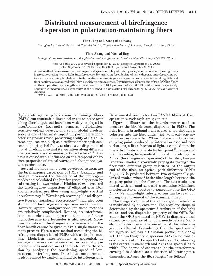
Figure 1 illustrates the interferometer used tomeasure the birefringence dispersion in PMFs. Thelight from a broadband light source is fed through apolarizer into the fiber under test, with only one po-larization mode excited. When there is a polarizationcoupling point produced by internal or external per-turbations, a little fraction of light is coupled into theunexcited mode at the disturbed point.9 Because ofthe wavelength-dependent modal birefringence�nb��� (birefringence dispersion) of the fiber, two po-larization modes dispersively propagate through thefiber with different group velocities. At the outputend of the fiber, an optical path difference (OPD)�nb���� l is produced between two orthogonally po-larized modes, where l is the fiber length between thecoupling point and the fiber end. The two modes aremixed with an analyzer, and a scanning Michelsoninterferometer is adopted to compensate for the OPD�nb���� l. white-light interferogram can be read outduring the movement of the scanning mirror.
The fringe visibility of the white-light interferenceis modulated by an envelope. The envelope shape isdetermined by the spectrum distribution of the lightsource and the dispersion property of the OPD. Be-cause the OPD produced in PMFs is dispersive andcannot be compensated for in a nondispersive Mich-elson interferometer, the envelope of the interfero-gram is affected. Considering that the spectrum ofthe light source has a Gaussian profile, and �� /�0�1, the birefringence dispersion �D can be consid-ered a constant in the spectral interval ��, where �0is the central wavelength and �� is the spectral half-width. The degree of coherence (or the interferenceenvelope) is deduced as a function of birefringencedispersion �D and the fiber length l as follows1:
2006 Optical Society of America
3412 OPTICS LETTERS / Vol. 31, No. 23 / December 1, 2006
��d��nb���l − d��
= �1 + �2�−1/4 exp�− � 2��Nbl − d�
�1 + �2�1/2W0�2 , �1�
where
� = ���/�0�22�c��D�l, �2�
�D = − ��02/�2�c���d2��/d�2�0, �3�
d is the OPD of the Michelson interferometer, �Nb isthe group birefringence of PMF, � is the accumula-tion of chromatic dispersion along fiber length l, c isthe light velocity in free space, and �� is the propa-gation constant difference of two polarization eigen-modes. W0 is the 1/e width of the interference enve-lope when the chromatic dispersion � is zero. Theenvelope width is also the coherence length of thelight source.
As shown in Eqs. (1) and (2), the interference en-velope width (or coherence length) is broadened bychromatic dispersion. It is directly proportional to thefiber length l from the coupling point to the outputend of fiber. It is also proportional to the birefrin-gence dispersion �D of the same fiber section. If theenvelope width of an interferogram is obtained, thebirefringence dispersion �D can be calculated as
�D 1
2�cl� �0
���2� W
W0� , �4�
with l=d /�Nb. W is the envelope width broadened bychromatic dispersion.
In the case of multiple weak coupling points, powercoupled from the launch mode into the unexcitedmode at any coupling point is small, so one couplingpoint produces only one white-light interferogram.9
Because each interferogram experiences differentchromatic dispersions of different fiber sections, ana-lyzing the envelope broadening of multiple interfero-grams, birefringence dispersions of particular fibersections can be evaluated. Assuming that l1 and l2and W1 and W2 are the positions and interference en-velope widths for two coupling points, respectively,the birefringence dispersion of the fiber section be-tween the two coupling points is obtained:
�D 1
2�c�l − l �� �0
���2�W2 − W1
W � . �5�
Fig. 1. Birefringence dispersion measurement system:SLD, superluminescent diode; F, force; L1, L2, lenses; M1,M2, mirrors; BS, beam splitter; SM, stepper motor; A, ana-lyzer; PD, photodiode; DAQ, data acquisition.
2 1 0
When there are multiple coupling points along thefiber at different positions, variation of birefringencedispersion along different fiber sections can be evalu-ated. Distributed measurement is realized. By apply-ing a least-squares linear fit to the measured datapoints, average birefringence dispersion for thewhole fiber can also be obtained to reduce randommeasurement error.
The experimental setup is shown in Fig. 1. A super-luminescent diode emitting at 1310 nm was used asthe light source. Its spectra followed a Gaussian dis-tribution, and the spectral half-width was approxi-mately 50 nm. The interference signal was detectedby an InGaAs PIN diode and then transmitted to apersonal computer by a programmable data acquisi-tion circuit.
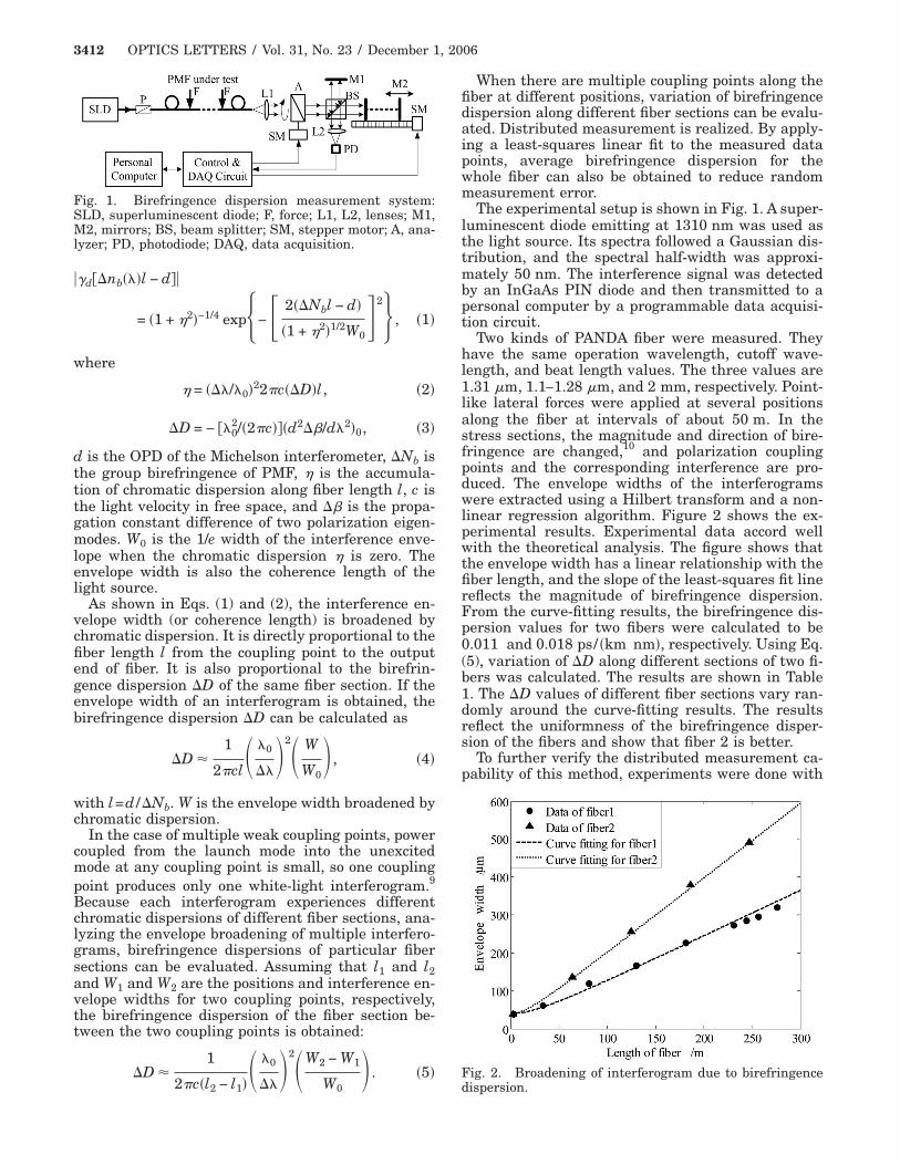
Two kinds of PANDA fiber were measured. Theyhave the same operation wavelength, cutoff wave-length, and beat length values. The three values are1.31 m, 1.1–1.28 m, and 2 mm, respectively. Point-like lateral forces were applied at several positionsalong the fiber at intervals of about 50 m. In thestress sections, the magnitude and direction of bire-fringence are changed,10 and polarization couplingpoints and the corresponding interference are pro-duced. The envelope widths of the interferogramswere extracted using a Hilbert transform and a non-linear regression algorithm. Figure 2 shows the ex-perimental results. Experimental data accord wellwith the theoretical analysis. The figure shows thatthe envelope width has a linear relationship with thefiber length, and the slope of the least-squares fit linereflects the magnitude of birefringence dispersion.From the curve-fitting results, the birefringence dis-persion values for two fibers were calculated to be0.011 and 0.018 ps/ �km nm�, respectively. Using Eq.(5), variation of �D along different sections of two fi-bers was calculated. The results are shown in Table1. The �D values of different fiber sections vary ran-domly around the curve-fitting results. The resultsreflect the uniformness of the birefringence disper-sion of the fibers and show that fiber 2 is better.
To further verify the distributed measurement ca-pability of this method, experiments were done with
Fig. 2. Broadening of interferogram due to birefringence
dispersion.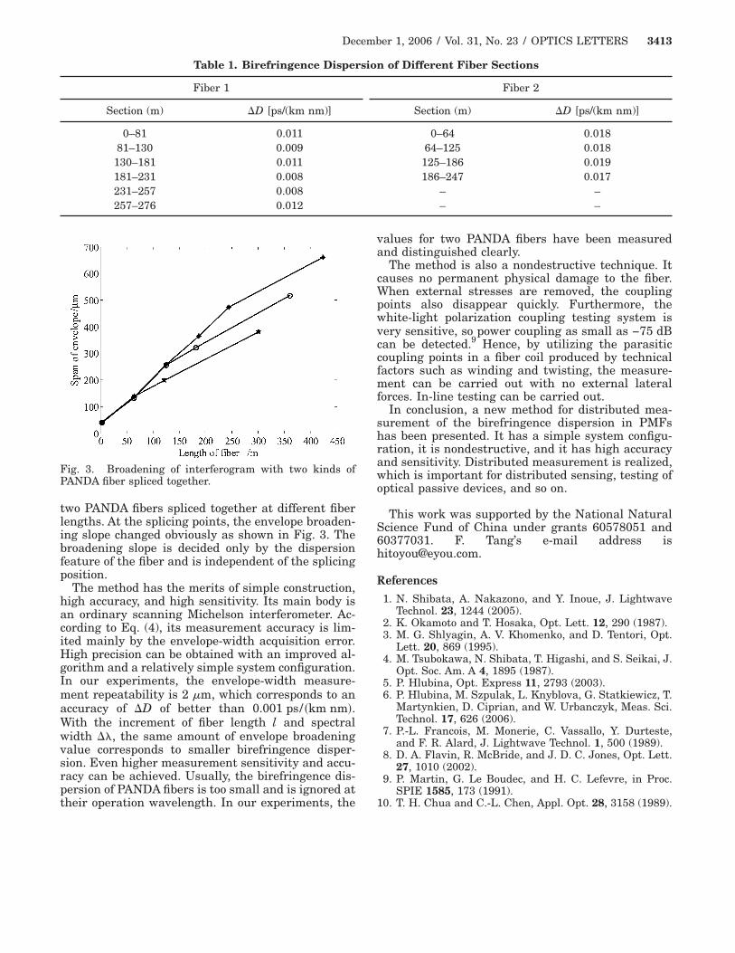
December 1, 2006 / Vol. 31, No. 23 / OPTICS LETTERS 3413
two PANDA fibers spliced together at different fiberlengths. At the splicing points, the envelope broaden-ing slope changed obviously as shown in Fig. 3. Thebroadening slope is decided only by the dispersionfeature of the fiber and is independent of the splicingposition.
The method has the merits of simple construction,high accuracy, and high sensitivity. Its main body isan ordinary scanning Michelson interferometer. Ac-cording to Eq. (4), its measurement accuracy is lim-ited mainly by the envelope-width acquisition error.High precision can be obtained with an improved al-gorithm and a relatively simple system configuration.In our experiments, the envelope-width measure-ment repeatability is 2 m, which corresponds to anaccuracy of �D of better than 0.001 ps/ �km nm�.With the increment of fiber length l and spectralwidth ��, the same amount of envelope broadeningvalue corresponds to smaller birefringence disper-sion. Even higher measurement sensitivity and accu-racy can be achieved. Usually, the birefringence dis-persion of PANDA fibers is too small and is ignored at
Table 1. Birefringence Disper
Fiber 1
Section (m) �D [ps/(km nm)]
0–81 0.01181–130 0.009
130–181 0.011181–231 0.008231–257 0.008257–276 0.012
Fig. 3. Broadening of interferogram with two kinds ofPANDA fiber spliced together.
their operation wavelength. In our experiments, the
values for two PANDA fibers have been measuredand distinguished clearly.
The method is also a nondestructive technique. Itcauses no permanent physical damage to the fiber.When external stresses are removed, the couplingpoints also disappear quickly. Furthermore, thewhite-light polarization coupling testing system isvery sensitive, so power coupling as small as −75 dBcan be detected.9 Hence, by utilizing the parasiticcoupling points in a fiber coil produced by technicalfactors such as winding and twisting, the measure-ment can be carried out with no external lateralforces. In-line testing can be carried out.
In conclusion, a new method for distributed mea-surement of the birefringence dispersion in PMFshas been presented. It has a simple system configu-ration, it is nondestructive, and it has high accuracyand sensitivity. Distributed measurement is realized,which is important for distributed sensing, testing ofoptical passive devices, and so on.
This work was supported by the National NaturalScience Fund of China under grants 60578051 and60377031. F. Tang’s e-mail address [email protected].
References
1. N. Shibata, A. Nakazono, and Y. Inoue, J. LightwaveTechnol. 23, 1244 (2005).
2. K. Okamoto and T. Hosaka, Opt. Lett. 12, 290 (1987).3. M. G. Shlyagin, A. V. Khomenko, and D. Tentori, Opt.
Lett. 20, 869 (1995).4. M. Tsubokawa, N. Shibata, T. Higashi, and S. Seikai, J.
Opt. Soc. Am. A 4, 1895 (1987).5. P. Hlubina, Opt. Express 11, 2793 (2003).6. P. Hlubina, M. Szpulak, L. Knyblova, G. Statkiewicz, T.
Martynkien, D. Ciprian, and W. Urbanczyk, Meas. Sci.Technol. 17, 626 (2006).
7. P.-L. Francois, M. Monerie, C. Vassallo, Y. Durteste,and F. R. Alard, J. Lightwave Technol. 1, 500 (1989).
8. D. A. Flavin, R. McBride, and J. D. C. Jones, Opt. Lett.27, 1010 (2002).
9. P. Martin, G. Le Boudec, and H. C. Lefevre, in Proc.SPIE 1585, 173 (1991).
n of Different Fiber Sections
Fiber 2
Section (m) �D [ps/(km nm)]
0–64 0.01864–125 0.018
125–186 0.019186–247 0.017
– –– –
sio
10. T. H. Chua and C.-L. Chen, Appl. Opt. 28, 3158 (1989).