distributed by raccordi in pvc-u u-pvc fittings...
TRANSCRIPT
Raccordi in PVC-U
PVC-U fittings
Raccords en PVC-U
Fittings aus PVC-U
FIPFormatura
Iniezione Polimeri
Loc. Pian di Parata 16015 Casella Genova Italytel. +39 010 9621.1 fax +39 010 [email protected]
Raccordi in PVC-UU-PVC fittingsRaccords en PVC-UFittings aus PVC-U
01
/20
09
Since 1954 FIP produces injection moulded valves and fittings in thermoplastic materials for pressure pipeline systems thus becoming nowadays the la rges t European va lves manufacturer. F IP i s a company o f the Aliaxis Group: a worldwide industrial holding gathering together a series of companies manufacturing and marketing plastic plumbing products for building industrial and public utilities applications.FIP products are manufactured on EU production sites, operating to the Quality Assurance System in compliance with ISO 9001 and with the Environmental Management System ISO 14001 standards requirements. In FIP products there are over 50 years of know-how powered by a strong quest for innovation.
01
/20
09
Distributed by
PV
C-U
fit
tin
gs

Raccordi in PVC-ULa gamma di raccordi in PVC-U comprende una serie completa di figure sia per saldatura chimica nel bicchiere che filettate e di passaggio per il convogliamento in pressione di fluidi e per temperature massime di esercizio non superiori a 60°C.L’intera linea è realizzata utilizzando resine di PVC-U conformi alla nuove normative EN 1452 e ISO 4422 ed ottemperanti ai requisiti DIN 8063 ed EN ISO 15493 per utilizzo di sistemi di tubazioni in materiali plastici nei processi industriali.I raccordi FIP in PVC-U sono riconosciuti per impiego a bordo di navi ed altre unità classificate dal RINA-Registro Italiano Navale, Bureau Veritas e Germanischer Lloyd.
Tra le principali proprietà e caratteristiche della linea in PVC-U si possono citare:
• Buona resistenza chimica: le resine PVC-U garantiscono una eccel-lente resistenza chimica nei confronti di buona parte di acidi ed alcali, idrocarburi alifatici e soluzioni saline. Composti organici clorurati, aro-matici e solventi possono invece intaccare la resistenza chimica del PVC-U. Le resine PVC-U offrono completa compatibilità anche nel tra-sporto di fluidi alimentari, acqua potabile e da potabilizzare, di acque demineralizzate secondo le vigenti norme nazionali ed internazionali.
• Buona stabilità termica: soprattutto nel campo di temperatura in-termedio tra 20°C e 50°C il PVC-U trova il suo tipico impiego garan-tendo prestazioni di eccellente resistenza meccanica, discreta rigidità, ridotti coefficienti di dilatazione termica ed elevati fattori di sicurezza nel servizio.
• Durata nel tempo: le resine PVC-U presentano un elevato valore del carico di rottura circonferenziale (Minimum Required Strenght MRS ≥ 25.0 MPa a 20°C) e consentono di ottenere tempi di vita della in-stallazioni estremamente lunghi, senza che si manifestino particolari decadimenti fisico-meccanici.
PVC-U FittingsThe PVC-U range is a complete range of fittings for solvent welding, th-readed connection for use in the construction of process and service lines to convey industrial fluids at maximum operating temperatures of 60°C.The entire range is produced using PVC-U resins compliant with the stan-dards EN 1452 and ISO 4422 and in observance of the requirements of DIN 8063 and EN ISO 15493 for the use of plastic pipes in industrial processes.
Main properties and characteristics:
• Good chemical resistance: PVC-U resins guarantee excellent chemi-cal resistance with regard to most acids and alkalis, aliphatic hydro-carbons and saline solutions. PVC-U resins are also totally compatible for the handling of food grade fluids, treated and untreated drinking water, as well as demineralised water according to current national and international standards.
• Good thermal stability: mostly in the intermediate temperature range between 20°C and 50°C, PVC-U finds its ideal application in industrial and water supplies, assuring optimal performance in terms of mechanical resistance, good rigidity, low coefficients of thermal ex-pansion and optimal safety factors in service.
• Lifetime: PVC-U resins feature is an high value in the material streng-th (Minimum Required Strength MRS ≥ 25.0 Mpa at 20°C) and an extremely extended lifetime.
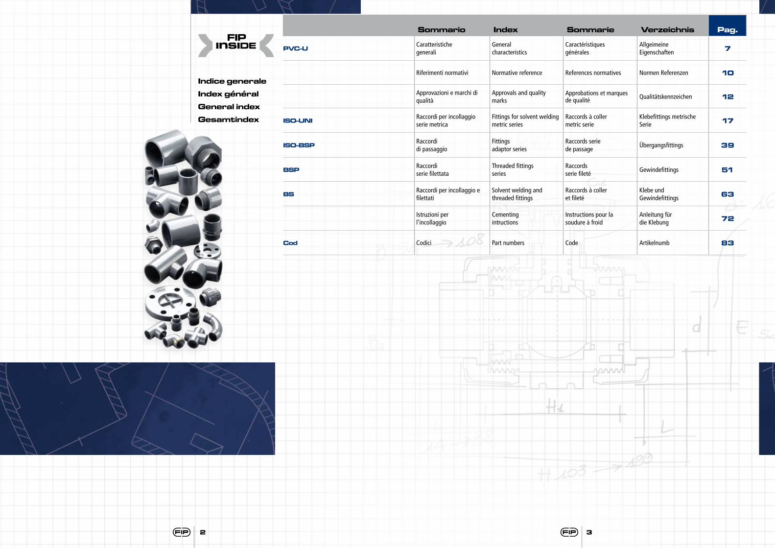
Indice generale
Index général
General index
Gesamtindex
Sommario Index Sommarie Verzeichnis Pag.
PVC-U Caratteristiche generali
General characteristics
Caractéristiquesgénérales
AllgeimeineEigenschaften 7
Riferimenti normativi Normative reference References normatives Normen Referenzen 10
Approvazioni e marchi di qualità
Approvals and quality marks
Approbations et marques de qualité Qualitätskennzeichen 12
ISO-UNI Raccordi per incollaggioserie metrica
Fittings for solvent welding metric series
Raccords à coller metric serie
Klebefittings metrische Serie 17
ISO-BSP Raccordi di passaggio
Fittingsadaptor series
Raccords seriede passage
Übergangsfittings 39
BSP Raccordi serie filettata
Threaded fittings series
Raccords serie fileté
Gewindefittings 51
BS Raccordi per incollaggio e filettati
Solvent welding and threaded fittings
Raccords à coller et fileté
Klebe und Gewindefittings 63
Istruzioni per l’incollaggio
Cementingintructions
Instructions pour la soudure à froid
Anleitung für die Klebung 72
Cod Codici Part numbers Code Artikelnumb 83
2 3
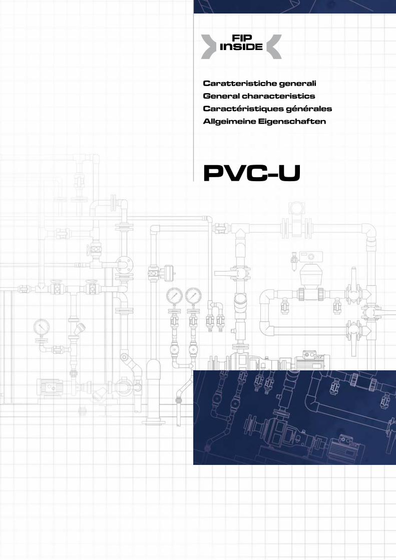
PVC-U
Caratteristiche generaliGeneral characteristicsCaractéristiques généralesAllgeimeine Eigenschaften
PVC-U
6
I dati del presente prospetto sono forniti in buona fede. La FIP non si assume alcu-na responsabilità su quei dati non diret-tamente derivati da norme internazionali. La FIP si riserva di apportarvi qualsiasi modifica.
The data given in this leaflet are offered in good faith. No liability can be accepted concerning technical data that are not directly covered by recognized interna-tional standards. FIP reserves the right to carry out any modification to the products shown in this Ieaflet.
Les données contenues dans cette brochure sont fournies en bonne foi. FIP n’assume aucune responsabilité pour les données qui ne dérivent pas directement des normes internationa-les. FIP garde le droit d’apporter toute modification aux produits présentés dans cette brochure.
Alle Daten dieser Druckschrift wurden nach bestem Wissen angegeben, jedoch besteht keine Verbindlichkeit, sofern sie nicht direkt internationalen Normen entnommen wurden. Die Än-derung von Maßen oder Ausführungen bleibt FIP vorbehalten.
PVC-U
7
PVC-UCaratteristiche generali
PVC-UGeneral characteristics
PVC-UCaractéristiquesgénérales
PVC-UAllgeimeineEigenschaften
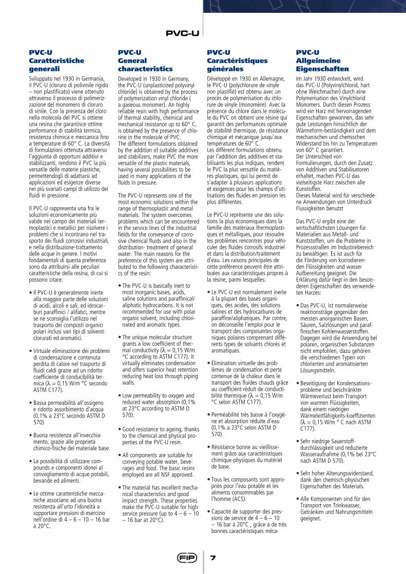
Sviluppato nel 1930 in Germania, il PVC-U (cloruro di polivinile rigido – non plastificato) viene ottenuto attraverso il processo di polimeriz-zazione del monomero di cloruro di vinile. Con la presenza del cloro nella molecola del PVC si ottiene una resina che garantisce ottime performance di stabilità termica, resistenza chimica e meccanica fino a temperature di 60° C. La diversità di formulazioni ottenuta attraverso l’aggiunta di opportuni additivi e stabilizzanti, rendono il PVC la più versatile delle materie plastiche, permettendogli di adattarsi ad applicazioni ed esigenze diverse nei più svariati campi di utilizzo dei fluidi in pressione.
Il PVC-U rappresenta una fra le soluzioni economicamente più valide nel campo dei materiali ter-moplastici e metallici per risolvere i problemi che si incontrano nel tra-sporto dei fluidi corrosivi industriali, e nella distribuzione-trattamento delle acque in genere. I motivi fondamentali di questa preferenza sono da attribuirsi alle peculiari caratteristiche della resina, di cui si possono citare:
•Il PVC-U è generalmente inerte alla maggior parte delle soluzioni di acidi, alcoli e sali, ed idrocar-buri paraffinici / alifatici, mentre se ne sconsiglia l’utilizzo nel trasporto dei composti organici polari inclusi vari tipi di solventi clorurati ed aromatici.
•Virtuale eliminazione dei problemi di condensazione e contenuta perdita di calore nel trasporto di fluidi caldi grazie ad un ridotto coefficiente di conducibilità ter-mica (λ = 0,15 W/m °C secondo ASTM C177).
•Bassa permeabilità all’ossigeno e ridotto assorbimento d’acqua (0,1% a 23°C secondo ASTM D 570)
•Buona resistenza all’invecchia-mento, grazie alle proprietà chimico-fisiche del materiale base.
•La possibilità di utilizzare com-pounds e componenti idonei al convogliamento di acque potabili, bevande ed alimenti.
•Le ottime caratteristiche mecca-niche associano ad una buona resistenza all’urto l’idoneità a sopportare pressioni di esercizio nell’ordine di 4 – 6 – 10 – 16 bar a 20°C.
Developed in 1930 in Germany, the PVC-U (unplasticized polyvinyl chloride) is obtained by the process of polymerization vinyl chloride ( a gaseous monomer). An highly reliable resin with high performance of thermal stability, chemical and mechanical resistance up to 60° C, is obtained by the presence of chlo-rine in the molecule of PVC. The different formulations obtained by the addition of suitable additives and stabilizers, make PVC the more versatile of the plastic materials, having several possibilities to be used in many applications of the fluids in pressure.
The PVC-U represents one of the most economic solutions within the range of thermoplastic and metal materials. The system overcomes problems which can be encountered in the service lines of the industrial fields for the conveyance of corro-sive chemical fluids and also in the distribution- treatment of general water. The main reasons for the preference of this system are attri-buted to the following characteristi-cs of the resin:
•The PVC-U is basically inert to most inorganic bases, acids, saline solutions and paraffinical/aliphatic hydrocarbons. It is not recommended for use with polar organic solvent, including chlori-nated and aromatic types.
•The unique molecular structure grants a low coefficient of ther-mal conductivity (λ = 0,15 W/m °C according to ASTM C177). It virtually eliminates condensation and offers superior heat retention reducing heat loss through piping walls.
•Low permeability to oxygen and reduced water absorption (0,1% at 23°C according to ASTM D 570).
•Good resistance to ageing, thanks to the chemical and physical pro-perties of the PVC-U resin.
•All components are suitable for conveying potable water, beve-rages and food. The basic resins employed are all NSF approved.
•The material has excellent mecha-nical characteristics and good impact strength. These properties make the PVC-U suitable for high service pressure (up to 4 – 6 – 10 – 16 bar at 20°C).
Développé en 1930 en Allemagne, le PVC-U (polychlorure de vinyle non plastifié) est obtenu avec un procès de polymérisation du chlo-rure de vinyle (monomère). Avec la présence du chlore dans le molécu-le du PVC on obtient une résine qui garantit des performances optimale de stabilité thermique, de résistance chimique et mécanique jusqu’aux températures de 60° C.Les diffèrent formulations obtenu par l’addition des additives et sta-bilisants les plus indiques, rendent le PVC la plus versatile du matiè-res plastiques, qui lui permit de s’adapter à plusieurs applications et exigences pour les champs d’uti-lisations des fluides en pression les plus différentes.
Le PVC-U représente une des solu-tions la plus économiques dans la famille des matériaux thermoplasti-ques et métalliques, pour résoudre les problèmes rencontrés pour véhi-culer des fluides corrosifs industriel et dans la distribution/traitement d’eau. Les raisons principales de cette préférence peuvent être attri-buées aux caractéristiques propres à la résine, parmi lesquelles:
•Le PVC-U est normalement inerte à la plupart des bases organi-ques, des acides, des solutions salines et des hydrocarbures de paraffine/aliphatiques. Par contre, on déconseille l’emploi pour le transport des composantes orga-niques polaires comprenant diffé-rents types de solvants chlorés et aromatiques.
•Élimination virtuelle des prob-lèmes de condensation et perte contenue de la chaleur dans le transport des fluides chauds grâce au coefficient réduit de conducti-bilité thermique (λ = 0,15 W/m °C selon ASTM C177).
•Perméabilité très basse à l’oxygè-ne et absorption réduite d’eau (0,1% a 23°C selon ASTM D 570).
•Résistance bonne au vieillisse-ment grâce aux caractéristiques chimique-physiques du matériel de base.
•Tous les composants sont appro-priés pour l’eau potable et les aliments consommables par l’homme (ACS).
•Capacité de supporter des pres-sions de service de 4 – 6 – 10 – 16 bar à 20°C , grâce à de très bonnes caractéristiques méca-
Im Jahr 1930 entwickelt, wird das PVC-U (Polyvinylchlorid, hart ohne Weichmacher) durch eine Polymerisation des Vinylchlorid Monomers. Durch diesen Prozess wird ein Harz mit hervorragenden Eigenschaften gewonnen, das sehr gute Leistungen hinsichtlich der Wärmeform-beständigkeit und dem mechanischen und chemischen Widerstand bis hin zu Temperaturen von 60° C garantiert.Der Unterschied von Formulierungen, durch den Zusatz von Additiven und Stabilisatoren erhaltet, machen PVC-U das vielseitigste Harz zwischen alle Kunstoffen.Dieses Material wird für verschiede-ne Anwendungen von Unterdruck Flussigkeiten benutzt
Das PVC-U ergibt eine der wirtschaftlichsten Lösungen für Materialien aus Metall- und Kunststoffen, um die Probleme in Prozessstraßen im Industriebereich zu bewältigen. Es ist auch für die Förderung von korrodieren-den Flüssigkeiten und wasser Aufbereitung geeignet. Die Erklärung dafür liegt in den beson-deren Eigenschaften des verwende-ten Harzes:
•Das PVC-U, ist normalerweise reaktionsträge gegenüber den meisten anorganischen Basen, Säuren, Salzlösungen und paraf-finischen Kohlenwasserstoffen. Dagegen wird die Anwendung bei polaren, organischen Substanzen nicht empfohlen, dazu gehören die verschiedenen Typen von chlorierten und aromatisierten Lösungsmitteln.
•Beseitigung der Kondensations-probleme und beschränkter Wärmeverlust beim Transport von warmen Flüssigkeiten, dank einem niedrigen Wärmeleitfähigkeits-koeffizienten (λ = 0,15 W/m ° C nach ASTM C177).
•Sehr niedrige Sauerstoff-durchlässigkeit und reduzierte Wasseraufnahme (0,1% bei 23°C nach ASTM D 570).
•Sehr hoher Alterungswiderstand, dank den chemisch-physischen Eigenschaften des Materials.
•Alle Komponenten sind für den Transport von Trinkwasser, Getränken und Nahrungsmitteln geeignet.
PVC-U
8
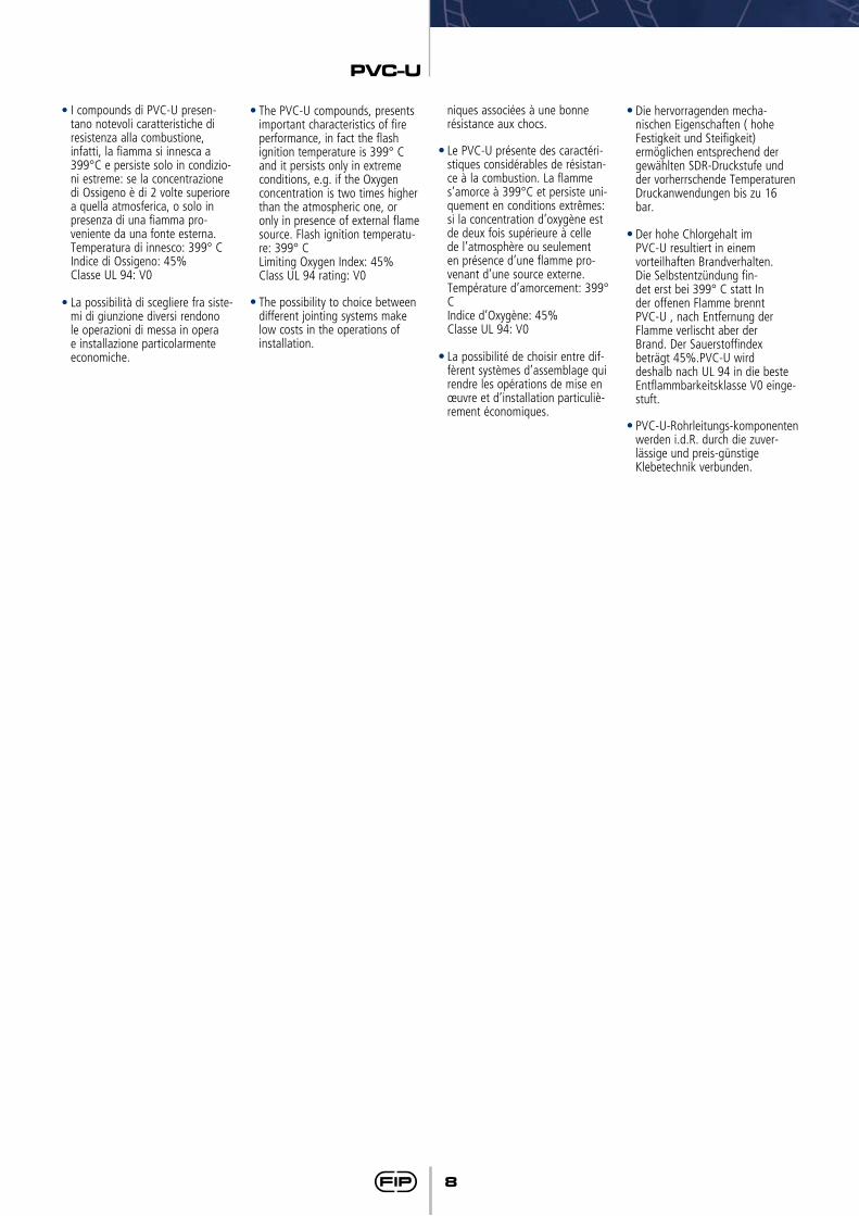
•I compounds di PVC-U presen-tano notevoli caratteristiche di resistenza alla combustione, infatti, la fiamma si innesca a 399°C e persiste solo in condizio-ni estreme: se la concentrazione di Ossigeno è di 2 volte superiore a quella atmosferica, o solo in presenza di una fiamma pro-veniente da una fonte esterna. Temperatura di innesco: 399° C
Indice di Ossigeno: 45% Classe UL 94: V0
•La possibilità di scegliere fra siste-mi di giunzione diversi rendono le operazioni di messa in opera e installazione particolarmente economiche.
•The PVC-U compounds, presents important characteristics of fire performance, in fact the flash ignition temperature is 399° C and it persists only in extreme conditions, e.g. if the Oxygen concentration is two times higher than the atmospheric one, or only in presence of external flame source. Flash ignition temperatu-re: 399° C
Limiting Oxygen Index: 45% Class UL 94 rating: V0
•The possibility to choice between different jointing systems make low costs in the operations of installation.
niques associées à une bonne résistance aux chocs.
•Le PVC-U présente des caractéri-stiques considérables de résistan-ce à la combustion. La flamme s’amorce à 399°C et persiste uni-quement en conditions extrêmes: si la concentration d’oxygène est de deux fois supérieure à celle de l’atmosphère ou seulement en présence d’une flamme pro-venant d’une source externe. Température d’amorcement: 399° C
Indice d’Oxygène: 45% Classe UL 94: V0
•La possibilité de choisir entre dif-fèrent systèmes d’assemblage qui rendre les opérations de mise en œuvre et d’installation particuliè-rement économiques.
•Die hervorragenden mecha-nischen Eigenschaften ( hohe Festigkeit und Steifigkeit) ermöglichen entsprechend der gewählten SDR-Druckstufe und der vorherrschende Temperaturen Druckanwendungen bis zu 16 bar.
•Der hohe Chlorgehalt im PVC-U resultiert in einem vorteilhaften Brandverhalten. Die Selbstentzündung fin-det erst bei 399° C statt In der offenen Flamme brennt PVC-U , nach Entfernung der Flamme verlischt aber der Brand. Der Sauerstoffindex beträgt 45%.PVC-U wird deshalb nach UL 94 in die beste Entflammbarkeitsklasse V0 einge-stuft.
•PVC-U-Rohrleitungs-komponenten werden i.d.R. durch die zuver-lässige und preis-günstige Klebetechnik verbunden.
PVC-U
9
VALOREVALUE / VALEUR
WERT
1,381,38
3000
50
50
80
50
76
86
0,150,15
8 x 10-58 x 10-5
4545
UNITÀ DI MISURAUNIT OF MEASURE / UNITÉ
DE MESURE / EINHEIT
g/cm3
g/cm3
MPa = N/mm2
J/m
%
Shore D
MPa = N/mm2
°C
°C
W/(m °C)W/(m °C)
m/(m °C)m/(m °C)
%%
METODO DI PROVATEST METHOD / MÉTHODE D’ESSAI
PRÜFMETHODE
ISO 1183ASTM D792
ISO 527
ASTM D256
ISO 527
ISO 868
ISO 527
ISO 306
ASTM D648
DIN 52612-1ASTM C177
DIN 53752ASTM D696
ISO 4859-1ASTM D2863
CARATTERISTICACHARACTERISTIC / CARACTÉRISTIQUE
EIGENSCHAFT
DensitàDensityDensitéDichte
Modulo di elasticitàFlexural Modulus
Module d’élasticitéElastitizitätsmodul
Resistenza IZOD con intaglio a 23°CIZOD notched impact strenght at 23°C
Résistance IZOD avec entaille à 23°CIZOD Widerstand mit Kerbe bei 23°C
Allungamento alla rotturaTensile elongation break Allongement à la rupture
Brchdehnung
Durezza ShoreRockwell Hardness
Dureté RockwellHärte Rockwell
Resistenza alla trazioneTensile strenght
Résistance à la tractionZugfestigkeit
Rammollimento VICAT (B/50)VICAT softening point (B/50)Ramollissement VICAT (B50)
Erweichungstemperatur VICAT (B/50)
Temperatura di Distorsione HDT (0,46 N/mm2)HDT bending temperature (0,46 N/mm2)
Température de distorsion HDT (0,46 N/mm2)Verformungstemperatur HDT (0,46 N/mm2)
Conducibilità Termica a 23°CThermal conductivity 23°C
Conductibilité thermique à 23°CWärmeleitfähigkeit bei 23°C
Coefficiente di dilatazione termica lineareCoefficient of linear thermal expansion
Coefficient de dilatation thermique linéaireLinearer Wärmeausdehnungskoeffizient
Indice limite di OssigenoLimiting Oxygen Index
Indice Limite d’OxygèneSauerstoffindex
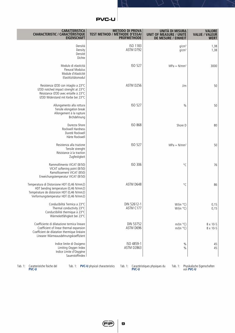
Tab. 1: Caratteristiche fisiche del PVC-U
Tab. 1: PVC-U physical characteristics Tab. 1: Caractéristiques physiques du PVC-U
Tab. 1: Physikalische Eigenschaften von PVC-U
PVC-U
10
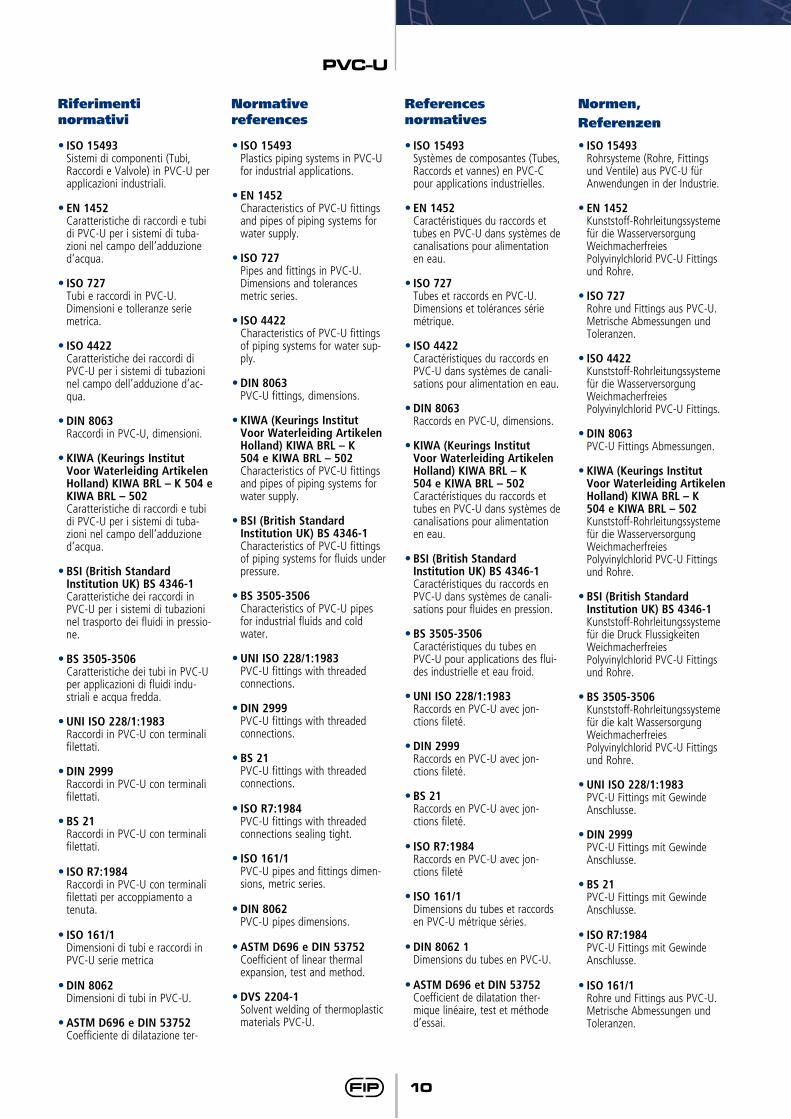
Riferimenti normativi
Normative references
Normen, Referenzen
References normatives
•ISO 15493 Sistemi di componenti (Tubi,
Raccordi e Valvole) in PVC-U per applicazioni industriali.
•EN 1452 Caratteristiche di raccordi e tubi
di PVC-U per i sistemi di tuba-zioni nel campo dell’adduzione d’acqua.
•ISO 727 Tubi e raccordi in PVC-U.
Dimensioni e tolleranze serie metrica.
•ISO 4422 Caratteristiche dei raccordi di
PVC-U per i sistemi di tubazioni nel campo dell’adduzione d’ac-qua.
•DIN 8063 Raccordi in PVC-U, dimensioni.
•KIWA (Keurings Institut Voor Waterleiding Artikelen Holland) KIWA BRL – K 504 e KIWA BRL – 502
Caratteristiche di raccordi e tubi di PVC-U per i sistemi di tuba-zioni nel campo dell’adduzione d’acqua.
•BSI (British Standard Institution UK) BS 4346-1 Caratteristiche dei raccordi in PVC-U per i sistemi di tubazioni nel trasporto dei fluidi in pressio-ne.
•BS 3505-3506 Caratteristiche dei tubi in PVC-U
per applicazioni di fluidi indu-striali e acqua fredda.
•UNI ISO 228/1:1983 Raccordi in PVC-U con terminali
filettati.
•DIN 2999 Raccordi in PVC-U con terminali
filettati.
•BS 21 Raccordi in PVC-U con terminali
filettati.
•ISO R7:1984 Raccordi in PVC-U con terminali
filettati per accoppiamento a tenuta.
•ISO 161/1 Dimensioni di tubi e raccordi in
PVC-U serie metrica
•DIN 8062 Dimensioni di tubi in PVC-U.
•ASTM D696 e DIN 53752 Coefficiente di dilatazione ter-
•ISO 15493 Plastics piping systems in PVC-U
for industrial applications.
•EN 1452 Characteristics of PVC-U fittings
and pipes of piping systems for water supply.
•ISO 727 Pipes and fittings in PVC-U.
Dimensions and tolerances metric series.
•ISO 4422 Characteristics of PVC-U fittings
of piping systems for water sup-ply.
•DIN 8063 PVC-U fittings, dimensions.
•KIWA (Keurings Institut Voor Waterleiding Artikelen Holland) KIWA BRL – K 504 e KIWA BRL – 502 Characteristics of PVC-U fittings and pipes of piping systems for water supply.
•BSI (British Standard Institution UK) BS 4346-1 Characteristics of PVC-U fittings of piping systems for fluids under pressure.
•BS 3505-3506 Characteristics of PVC-U pipes
for industrial fluids and cold water.
•UNI ISO 228/1:1983 PVC-U fittings with threaded
connections.
•DIN 2999 PVC-U fittings with threaded
connections.
•BS 21 PVC-U fittings with threaded
connections.
•ISO R7:1984 PVC-U fittings with threaded
connections sealing tight.
•ISO 161/1 PVC-U pipes and fittings dimen-
sions, metric series.
•DIN 8062 PVC-U pipes dimensions.
•ASTM D696 e DIN 53752 Coefficient of linear thermal expansion, test and method.
•DVS 2204-1 Solvent welding of thermoplastic
materials PVC-U.
•ISO 15493 Systèmes de composantes (Tubes,
Raccords et vannes) en PVC-C pour applications industrielles.
•EN 1452 Caractéristiques du raccords et
tubes en PVC-U dans systèmes de canalisations pour alimentation en eau.
•ISO 727 Tubes et raccords en PVC-U.
Dimensions et tolérances série métrique.
•ISO 4422 Caractéristiques du raccords en
PVC-U dans systèmes de canali-sations pour alimentation en eau.
•DIN 8063 Raccords en PVC-U, dimensions.
•KIWA (Keurings Institut Voor Waterleiding Artikelen Holland) KIWA BRL – K 504 e KIWA BRL – 502 Caractéristiques du raccords et tubes en PVC-U dans systèmes de canalisations pour alimentation en eau.
•BSI (British Standard Institution UK) BS 4346-1 Caractéristiques du raccords en PVC-U dans systèmes de canali-sations pour fluides en pression.
•BS 3505-3506 Caractéristiques du tubes en
PVC-U pour applications des flui-des industrielle et eau froid.
•UNI ISO 228/1:1983 Raccords en PVC-U avec jon-
ctions fileté.
•DIN 2999 Raccords en PVC-U avec jon-
ctions fileté.
•BS 21 Raccords en PVC-U avec jon-
ctions fileté.
•ISO R7:1984 Raccords en PVC-U avec jon-
ctions fileté
•ISO 161/1 Dimensions du tubes et raccords
en PVC-U métrique séries.
•DIN 8062 1 Dimensions du tubes en PVC-U.
•ASTM D696 et DIN 53752 Coefficient de dilatation ther-mique linéaire, test et méthode d’essai.
•ISO 15493 Rohrsysteme (Rohre, Fittings
und Ventile) aus PVC-U für Anwendungen in der Industrie.
•EN 1452 Kunststoff-Rohrleitungssysteme
für die Wasserversorgung Weichmacherfreies Polyvinylchlorid PVC-U Fittings und Rohre.
•ISO 727 Rohre und Fittings aus PVC-U.
Metrische Abmessungen und Toleranzen.
•ISO 4422 Kunststoff-Rohrleitungssysteme
für die Wasserversorgung Weichmacherfreies Polyvinylchlorid PVC-U Fittings.
•DIN 8063 PVC-U Fittings Abmessungen.
•KIWA (Keurings Institut Voor Waterleiding Artikelen Holland) KIWA BRL – K 504 e KIWA BRL – 502 Kunststoff-Rohrleitungssysteme für die Wasserversorgung Weichmacherfreies Polyvinylchlorid PVC-U Fittings und Rohre.
•BSI (British Standard Institution UK) BS 4346-1 Kunststoff-Rohrleitungssysteme für die Druck Flussigkeiten Weichmacherfreies Polyvinylchlorid PVC-U Fittings und Rohre.
•BS 3505-3506 Kunststoff-Rohrleitungssysteme
für die kalt Wassersorgung Weichmacherfreies Polyvinylchlorid PVC-U Fittings und Rohre.
•UNI ISO 228/1:1983 PVC-U Fittings mit Gewinde
Anschlusse.
•DIN 2999 PVC-U Fittings mit Gewinde
Anschlusse.
•BS 21 PVC-U Fittings mit Gewinde
Anschlusse.
•ISO R7:1984 PVC-U Fittings mit Gewinde
Anschlusse.
•ISO 161/1 Rohre und Fittings aus PVC-U.
Metrische Abmessungen und Toleranzen.
PVC-U
11
mica lineare, test e metodo di prova.
•DVS 2204-1 Incollaggio di materiali termopla-
stici PVC-U.
•UNI 11242 Giunzione mediante incollaggio di
tubi, raccordi e valvole in PVC-U
La produzione delle linee in PVC-U è realizzata seguendo i più alti standard qualitativi e nel comple-to rispetto dei vincoli ambientali imposti dalle leggi vigenti. Tutti i prodotti sono realizzati in accordo al sistema di garanzia della qualità secondo la norma ISO 9001. Per maggiori informazioni visitare il sito: www.fipnet.it
•UNI 11242 Solvent welding of PVC-U pipes, fittings and valves
The production of the PVC-U lines, is in accordance with the highest quality standards and in full obser-vance of the environmental practi-ces imposed by current legislation. All products are manufactured in accordance with ISO 9001 certified quality assurance programme. For more information please visit our website: www.fipnet.it
•DVS 2204-1 soudure chimique de matériaux
thermoplastiques PVC-U
•UNI 11242 Soudre chimique de tube, raccords
et vannes en PVC-U
La production des lignes en PVC-U est réalisé suivant les normes de qualité actuelles et en respectant la protection de l’environnement selon les lois en vigueur.Tous les produits sont réalisés en accord avec le système de garan-tie de la qualité conformément à la Norme ISO 9001. Pour avoir d’autres informations, visiter le site: www.fipnet.it
•DIN 8062 PVC-U Rohre Abmessungen.
•ASTM D696 und DIN 53752 Lineare Längenausdehnung, Prüfung und Methode.
•DVS 2204-1 Kleben von thermoplastischen
Kunstoffen PVC-U
•UNI 11242 Kleben von Rohre, fittings und
ventile aus PVC-U
Die Herstellung von PVC-U erfolgt nach den höchsten Qualitätsanforderungen und in Übereinstimmung mit den gängigen Umweltschutzver-ordnungen. Alle Produkte werden nach der Norm ISO 9001 gefertigt. Für weitere Details schauen Sie auf unsere Website: www.fipnet.it

PVC-U
12
Approvazioni e marchi di qualità
Approvals and quality marks
QualitätskennzeichenApprobations et marques de qualité
•IIP N. 122 Istituto Italiano dei Plastici
Raccordi in PVC-U in accordo alla norma UNI EN 1452.
•ACS Francia (Attestation de conformité Sanitaire) N. 98 MAT NY 418
Idoneità del PVC-U per applica-zione alimentari.
•BSI (British Standard Institution UK) Certificato N. KM 05802
Raccordi in PVC-U in accordo alla norma BS 4346-1
•NSF (National Sanitation Foundation USA) Certificato N. 11370/11371A
Idoneità del PVC-U per il traspor-to di acqua potabile.
•WRAS (Water regulations advisory scheme - UK) Certificato N. M103019 Idoneità del PVC-U per il traspor-to di acqua potabile.
•KIWA (Keurings Institut Voor Waterleiding Artikelen Holland) Certificato N. K5034/01 Raccordi in PVC-U in accordo alla norma KIWA BRL K504
• IRH I raccordi FIP in PVC-U sono
riconosciuti da IRH per ACS. Certificato N. 05 MAT NY 006
•BUREAU VERITAS (Francia) Certificato N. 07123 / C0 BV
Idoneità del PVC-U per convo-gliamento, trattamento di acque sanitarie e di condizionamento nel settore navale.
•I raccordi FIP in PVC-U sono cer-tificati in accordo con le regola-mentazioni Ucraine per Sicurezza, Igiene e Qualità. Certificato N. UA1.094.0052575-04
•RINA – Registro Italiano Navale Certificato
N. MAC/36401/TO/01 Idoneità del PVC-U per convo-
gliamento, trattamento di acque sanitarie e di condizionamento nel settore navale.
•IIP N. 122 Istituto Italiano dei Plastici
(Italian Institute of Plastics) PVC-U fittings according to UNI EN 1452
•ACS France (Attestation de conformité Sanitaire)
N. 98 MAT NY 418 Suitability of PVC-U for alimenta-
ry applications.
•BSI (British Standard Institution UK) Licence N. KM 05802
PVC-U fittings according to BS 4346-1.
•NSF (National Sanitation Foundation USA) Certificate N. 11370/11371A
Suitability of PVC-U for use with drinking water.
•WRAS (Water regulations advisory scheme - UK) Certificate N. M103019 Suitability of PVC-U for use with drinking water.
•KIWA (Keurings Institut Voor Waterleiding Artikelen Holland) Certificato N. K5034/01 PVC-U fittings accor-ding to KIWA BRL K504
•IRH FIP PVC-U fittings are acknow-
ledged by IRH for ACS Certificate N. 05 MAT NY 006
•BUREAU VERITAS (France) Certificate N. 07123 / C0 BV
Suitability of PVC-U for transport and treatment of sanitary water and of conditioning for naval applications.
•FIP PVC-U fittings are cer-tified in accompliance with Ucrainian hygienic, safety and quality regulation. Certificate N. UA1.094.0052575-04
•RINA – Registro Italiano Navale (Italian Register Naval) Certificate N. MAC/36401/TO/01
Suitability of PVC-U for transport and treatment of sanitary water and of conditioning for naval applications.
•IIP N. 122 Istituto Italiano dei Plastici
(Institut Italienne des Plastics) Raccords en PVC-U en accord a UNI EN 1452
•ACS France (Attestation de conformité Sanitaire)
N. 98 MAT NY 418 conformité du PVC-U pour appli-
cations alimentaires.
•BSI (British Standard Institution UK) Certificat N. KM 05802
Raccords en PVC-U en accord a BS 4346-1.
•NSF (National Sanitation Foundation USA) Certificat N. 11370/11371A
Conformité du PVC-U pour le transport d’eau potable.
•WRAS (Water regulations advisory scheme - UK) Certificat N. M103019 Conformité du PVC-U pour le transport d’eau potable.
•KIWA (Keurings Institut Voor Waterleiding Artikelen Holland) Certificat N. K5034/01 04 Raccords en PVC-U en accord a KIWA BRL K504
•IRH Le raccords FIP en PVC-U sont
reconnus par IRH pour ACS. Certificat N. 05 MAT NY 006
•BUREAU VERITAS (France) Certificat N. 07123 / C0 BV
Conformité du PVC-U pour la canalisation, le traitement d’eaux sanitaires et de conditionnement dans le secteur naval.
•Le raccords FIP en PVC-U sont certifiés selon les réglementa-tions ukrainiennes pour Sûreté , Hygiène et Qualité. Certificat N. UA1.094.0052575-04.
•RINA - Registro Italiano Navale (Registre Italienne Naval) Certificate N. MAC/36401/TO/01 Conformité du PVC-U pour la canalisation, le traitement d’eaux sanitaires et de conditionnement dans le secteur naval.
•IIP N. 122 Istituto Italiano dei Plastici (Kunstoff Italienisch Institute)
PVC-U Fittings nach UNI EN 1452.
•ACS Frankreich (Attestation de conformité Sanitaire)
N. 98 MAT NY 418 Eignung des PVC-U zum Einsatz
mit Nahrungsmitteln.
•BSI (British Standard Institution UK) Zertifikation N. KM 05802
PVC-U Fittings nach BS 4346-1.
•NSF (National Sanitation Foundation USA) Zertifikation N. 11370/11371A
Eignung von PVC-U für Trinkwasserleitungen.
•WRAS (Water regulations advisory scheme - UK) Zertifikation N. M103019
Eignung von PVC-U für Trinkwasserleitungen.
•KIWA (Keurings Institut Voor Waterleiding Artikelen Holland) Zertifikation N. K5034/01
PVC-U Fittings nach KIWA BRL K504
•IRH Die Fittings FIP aus PVC-U sind
von IRH für ACS anerkennt. Zertifikat N. 05 MAT NY 006
•BUREAU VERITAS – (Frankreich) Zertifikation N. 07123 / C0 BV
Eignung von PVC-U für die Förderung und Behandlung von Sanitär- und Aufbereitungswasser im Schiffsbereich.
•Die FIP Fittings aus PVC-U sind entsprechend den ukrainischen Reglegungen für Sicherheit, Hygiene und Qualität bestätigt. Zertifikat N. UA1.094.0052575-04.
•RINA Registro Italiano Navale (Italienische Nautische Klassifikationsgesellschaft) Eignung von PVC-U für die Förderung und Behandlung von Sanitär- und Aufbereitungswasser im Schiffsbereich.
PVC-U
13
ISO 9001

Raccordi per incollaggio serie metricaFittings for solvent welding metric seriesRaccords à coller metric serieKlebefittings metrische Serie
ISO-UNI

16
PVC-U ISO-UNI
I dati del presente prospetto sono forniti in buona fede. La FIP non si assume alcu-na responsabilità su quei dati non diret-tamente derivati da norme internazionali. La FIP si riserva di apportarvi qualsiasi modifica.
The data given in this leaflet are offered in good faith. No liability can be accepted concerning technical data that are not directly covered by recognized interna-tional standards. FIP reserves the right to carry out any modification to the products shown in this Ieaflet.
Les données contenues dans cette brochure sont fournies en bonne foi. FIP n’assume aucune responsabilité pour les données qui ne dérivent pas directement des normes internationa-les. FIP garde le droit d’apporter toute modification aux produits présentés dans cette brochure.
Alle Daten dieser Druckschrift wurden nach bestem Wissen angegeben, jedoch besteht keine Verbindlichkeit, sofern sie nicht direkt internationalen Normen entnommen wurden. Die Än-derung von Maßen oder Ausführungen bleibt FIP vorbehalten.
17
PVC-U ISO-UNI
•Gamma dimensionale da d 12 mm a d 500 mm
•Resistenza a pressioni di esercizio fino a 16 bar a 20° C (acqua)
•Temperatura massima di esercizio: 60° C
•Materiale: Cloruro di polivinile rigido PVC-U
•Colore: grigio RAL 7011
•Sistema di giunzione mediante sal-datura chimica a freddo (incollag-gio) attraverso l’utilizzo di idoneo collante/adesivo
•Guarnizioni in EPDM o FPM
•Size range: from d 12 mm up to d 500 mm
•Pressure rating: max working pres-sure 16 bar at 20° C (water)
•Maximum working temperature: 60° C
•Material: Unplasticized poly vinyl chloride PVC-U
•Colour: grey RAL 7011
•Jointing technique: Cold (chemical) welding using solvent cement
•Sealing gaskets: EPDM or FPM
•Gamme dimensionnelle de d 12 mm au d 500 mm
•Résistance aux pressions de servi-ce jusqu’à 16 bar à 20° C (eau)
•Température maximale de service: 60° C
•Matériel: Polychlorure de vinyle non plastifié PVC-U
•Coleur: gris RAL 7011
•Système de jonction avec soudure chimique à froid (encollage) en utilisant un polymère de soudure (adhésif) préconisé
•Joints en EPDM ou FPM
•Abmessungen von d 12 mm bis d 500 mm
•Druckstufe bis PN 16 bar bei 20° C (Wasser)
•Maximale Betriebstemperatur: 60° C
•Material: Polyvinylchlorid, hart ohne Weichmacher PVC-U
•Farbe: grau RAL 7011
•Verbindungstechnik: Kleben, Kaltschweissung mit Klebstoff
•Dichtungen aus EPDM - FPM
Raccordi per incollaggio serie metrica
Fittings for solvent welding metric series
Klebefittings metrische Serie
Raccords à coller metric serie
Legenda
d diametro nominale esterno del tubo in mm
DN diametro nominale interno in mm
PN pressione nominale in bar (pressione max di esercizio a 20° C - acqua)
g Peso in grammi
U numero di fori
K chiave
b bulloni
C codice di riferimento o-ring
PVC-U polivinile di cloruro rigido. MRS-25
FPM (FKM) fluoroelastomero
EPDM elastomero etilene pro-pilene
d nominal outside diameter of the pipe in
mm
DN nominal internal diameter in mm
PN nominal pressure in bar (max working pressure
at 20° C – water)
g weight in grams
U number of holes
K key
b bolts
C o-ring code
PVC-U un-plasticized poly vinyl chloride. MRS-25
FPM (FKM) vinylidene fluoride rubber
EPDM ethylene propylene rubber
d diamètre extérieur nominal du tube en mm
DN diamètre intérieur nominal en mm
PN pression nominale en bar (pression maximale de service 20° C – eau)
g Poids en grammes
U nombre de trous
K clef
b boulons
C référence O-rin
PVC-U polychlorure de vinyle non plastifié. MRS-25
FPM (FKM) fluoro-élastomère
EPDM élastomère éthylène propylène
d Aussendurchmesser des Rohres, in mm
DN Innendurchmesser (NW), in mm
PN Nenndruck in bar (maximaler Betriebsdruck bei Wasser 20° C)
g Gewicht in Gramm
U Lochzahl
K Schlüsselweite
b Schrauben
C O-Ring Code
PVC-U Polyvinylchlorid, hart ohne Weichmacher. MRS-25
FPM (FKM) Fluorelastomer
EPDM Ethylen-Propylen-Dien Elastomer
18
PVC-U ISO-UNI
Dati Tecnici
Technical Data
Données Techniques
Technische Daten
1
3
1
2
2
4
10 h 10 2 1 10 3 10 5 0, 1 bar
50
30
25
10 6
20
10 4
40
15
10 9 8 7 6
5 4
3, 5 3
2, 5 2
1, 5
1
0, 5
1 5 1 0 2 5 5 0 100 Anni/Y ears/Années/Jahre
20 ° C 30 ° C 40 ° C
50 ° C
60 ° C
10 -1 h bar
1 1 0 1 0 2 10 3 10 5
70 60
16
10
3 2
10 4 10 6
A 0
B 0C 0
A 1
A 2B 1 B 2C 1 C 2
1 2 5 5 0
Tens
ione
tang
enzia
le -
Hoop
sre
ss -
Tens
ion
tang
entie
lle V
ergl
eich
sspa
nnun
g σv
[MPa
]
Durata di vita - Time to failureDurée - Standzeit
anni - years - années - Jahre
bar
16
14
12
10
8
6
4
2
0
20 40 ° C 60 100 0 80
pres
sione
di e
serc
izio
- wor
king
pre
ssur
epr
essio
n de
ser
vice
- Bet
riebs
druc
k
temperatura di esercizio - working temperaturetempérature de service - Betriebstemperatur
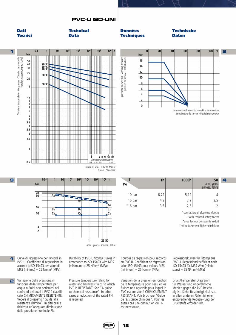
Curve di regressione per raccordi in PVC-U. Coefficienti di regressione in accordo a ISO 15493 per valori di MRS (minimo) = 25 N/mm2 (MPa)
Durability of PVC-U fittings Curves in accordance to ISO 15493 with MRS (minimum) = 25 N/mm2 (MPa)
Courbes de régression pour raccords en PVC-U. Coefficient de régression selon ISO 15493 pour valeurs MRS (minimum) = 25 N/mm2 (MPa)
Regressionskurven für Fittings aus PVC-U. Regressionskoeffizient nach ISO 15493 für MRS Wert (minde-stens) = 25 N/mm2 (MPa)
Variazione della pressione in funzione della temperatura per acqua o fluidi non pericolosi nei confronti dei quali il PVC è classifi-cato CHIMICAMENTE RESISTENTE. Vedere il prospetto “Guida alla resistenza chimica”. In altri casi è richiesta un’adeguata diminuzione della pressione nominale PN.
Pressure temperature rating for water and harmless fluids to which PVC is RESISTANT. See “A guide to chemical resistance”. In other cases a reduction of the rated PN is required.
Variation de la pression en fonction de la température pour l’eau et les fluides non agressifs pour lequel le PVC est considéré CHIMIQUEMENT RESISTANT. Voir brochure “Guide de résistance chimique”. Pour les autres cas une diminution du PN est nécessaire.
Druck/Temperatur Diagramm für Wasser und ungefährliche Medien gegen die PVC bestän-dig ist. Siehe Beständigkeitsli-ste. In allen anderen FälIen ist eine entsprechende Reduzie-rung der Druckstufe erforder-lich.
1h
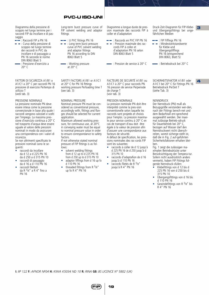
6,72
4,2
3,3
10 bar
16 bar
*16 bar
PeT 1000h
5,12
3,2
2,5
50anni, years
années, Jahre
4
2,5
2
*con fattore di sicurezza ridotto*with reduced safety factor
*avec facteur de securité réduit*mit reduziertem Sicherheitsfaktor
19
PVC-U ISO-UNI
3
4
Diagramma della pressione di scoppio nel lungo termine per i raccordi FIP da incollare e di pas-saggio : Raccordi FIP a PN 16 : Curva della pressione di
scoppio nel lungo termine dei raccordi in PVC da incollare e di passaggio a PN 16 secondo le norme DIN 8063 Blatt 5
: Pressione d’esercizio a 20° C
FATTORI Dl SICUREZZA A1/B1 oA1/C1 a 20° C per raccordi PN 16 pressione di esercizio Pe/tempo di utilizzo T(vedi tab. 3)
PRESSIONE NOMINALELa pressione nominale PN deve essere intesa come la pressione convenzionale in base alla quale i raccordi vengono calcolati e scelti per l’impiego. La massima pres-sione d’esercizio continua a 20° C nel trasporto d’acqua deve essere uguale al valore delle pressioni nominali in modo da assicurare una corrispondenza con i valori di sicurezza.Se non altrimenti specificato le pressioni nominali sono le se-guenti:• raccordi da incollare da d 12 a d 225 PN 16 da d 250 a d 315 PN 10• raccordi di passaggio da d 16 a d 110 PN 16• raccordi filettati da R 3/8” a R 4” fino a PN 16
Long-term burst pressure curve of FIP solvent welding and adaptor fittings : U PVC fittings PN 16 : Long term burst pressure
curve of PVC solvent welding and adaptor fittings PN 16 according to DIN 8063 Blatt 5
: Working pressure at 20° C
SAFETY FACTORS A1/B1 or A1/C1 at 20° C for PN 16 fittingsworking pressure Pe/loading time T(see tab. 3)
NOMINAL PRESSURENominal pressure PN must be con-sidered as conventional pressure, accordingly with, fittings and flan-ges should be selected for current application.Maximum allowed working pres-sure, for continuous use, at 20°C in conveying water must be equal to nominal pressure value in order to ensure correspondance to safety factors.If not otherwise stated nominal pressure of FIP fittings is as fol-lows:• solvent welding fittings from d 12 up to d 225 PN 16
from d 250 up to d 315 PN 10• adaptor fiffings from d 16 up fo
d 110 PN 16 • threaded fittings from R 3/8”
up fo R 4” PN 16
Diagramme a longue durée de pres-sion maximale des raccords FIP à coller et d’adaptation : Raccords en PVC FIP PN 16 : Pression maximale des rac-
cords FIP à coller et d’adaptation PN 16 selon
DIN 8063 Blatt 5
: Pression de service à 20° C
FACTEURS DE SECURITÉ A1/B1 ou A1/C1 à 20° C pour raccords PN 16 pression de service Pe/periode de charge T(voir tab. 3)
PRESSION NOMINALELa pression nominale PN doit être interprété comme la pres-sion conventionelle selon laquelle les raccords sont projetés et choisis pour l’emploi. La pression maxima-le pour service continu à 20° C en cas de transport d’eau doit être égale à la valeur de pression afin d’assurer une correspondance aux facteurs de sécurité.A défaut de specification, les pres-sions nominales des rac-cords FIP sont les suivantes:• raccords à coller de d 12 jusqu’à
d 225 PN 16 de d 250 jusqu’à d 315 PN 10
• raccords d’adaptafion de d 16 jusqu’à d 110 PN 16
• raccords filetés de R 3/8” jusqu’à R 4” PN 16
Druck-Zeit-Diagramm für FIP-Klebe- und Ubergangsfittings bei unge-fàhrlichen Medien
: FIP Fiffings PN 16 : Mindestzeitstandwerte für Klebe-und Ùbergangsfiffings PN 16 (entsprechend DIN 8063, Blatt 5)
: Betriebsdruck bei 20° C
SICHERHEITSFAKTOR A1/B1 oder A1/C1 bei 20° C für Fittings PN 16 Betriebsdruck Pe/Zeit T(siehe Tab. 3)
NENNDRUCKDer Nenndruck (PN) muß als Bezugsgröße verstanden wer-den, nach der Fittings berech-net und dem Bedarfstall ent-sprechend ausgewählt werden. Der maxi-mal zulässige Betrieb-sdruck für Dauerbetrieb bei 20° C, bezogen auf Wasser darf den Nenndruckwert nicht übersch-reiten, womit sicherge-stellt ist, daß die in Fig. 2 auf-geführten Sicherheitsfaktoren erhalten blei-ben.Fig. 1 zeigt die zulässigen ma-ximalen Betriebsdrücke unter Berücksichtigung der Tempera-tur. Sofern nicht ausdrücklich anders vermerkt, haben FIP Fittings fol-gende Nenndruck-sfufen:• Klebefittings von d 12 bis d
225 PN 16 von d 250 bis d 315 PN 10
• Übergangsfittings von d 16 bis d 110 PN 16
• Gewindefittings von R 3/8” bis R 4” PN 16
I: IIP 122 F: AFNOR NF04 H: KIWA K5034 ND 10 R: RINA GB: BS LICENCE N° 5802 (UK)

20
PVC-U ISO-UNI
Dimensioni Dimensions Dimensions DimensionenLa FIP ha approntato una gamma di raccordi i cui attacchi sono in accordo con le seguenti norme:Incollaggio: ISO 727, ISO 15493, DIN 8063, NF EN 1452, KIWA, BRL-K504, UNI-EN 1452 accoppiabili con tubi secondo ISO 161/1, UNI-EN 1452, ISO 15493, DIN 8062, NF EN 1452, KIWA BRL-502.
FIP have produced a complete range of fittings whose couplings comply with the following stan-dards:Solvent welding: ISO 727, ISO 15493, DIN 8063, NF EN 1452, KIWA, BRL-K504, UNI-EN 1452 coupling to pipes complying withISO 161/1, UNI-EN 1452, ISO 15493, DIN 8062, NF EN 1452, KIWA BRL-502.
FIP a crée une gamme complè-te de raccords dont les raccords con-formes aux normes suivantes:Collage: ISO 727, ISO 15493, DIN 8063, NF EN 1452, KIWA, BRL-K504, UNI-EN 1452 assemblés à des tubes selon ISO 161/1, UNI-EN 1452, ISO 15493, DIN 8062, NF EN 1452, KIWA BRL-502.
FIP-Fittings aus PVC-hart ent-sprechen in ihren Anschlüssen folgenden Normen:Klebefittings: ISO 727, ISO 15493, DIN 8063, NF EN 1452, KIWA, BRL-K504, UNI-EN 1452 und können ver-bunden werden mit Rohren nach ISO 1616/1, UNI-EN 1452, ISO 15493, DIN 8062, NF EN 1452, KIWA BRL-502.
SIVCURVA A 90° GRANDE RAGGIO (R=2d) estremità a bicchiere per incollaggio
**fattore di sicurezza ridotto
BEND 90° LONG RADIUS (R=2d) sockets for solvent welding
**reduced safety factor
COURBE 90° GRAND RAYON (R=2d) femelles à coller
**facteur de securité réduit
BOGEN 90°beidseitig Klebeanschluß21.000.01
**mit reduziertem Sicherheits- faktor
g
3555
100175280515
1000177028005020
Z
40,550
65,580,5
100,5127150180220207
E
27334150617694
113137189
L
16192226313844516186
PN
16161616161616161616
d
2025324050637590
110**160
IHRIHRIHRIHRIHRIHR
IRIRIR
(PN 10) I
I: IIP 122 H: KIWA K5034 ND 10 R: RINA
21
PVC-U ISO-UNI
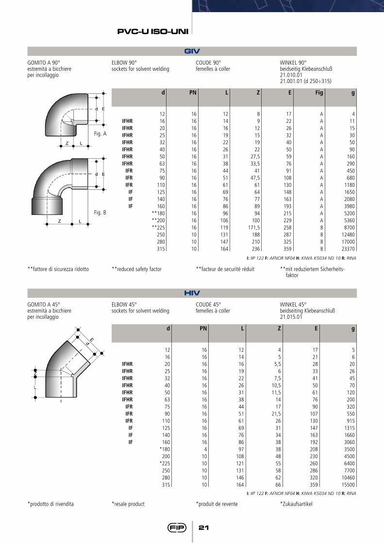
GIVGOMITO A 90°estremità a bicchiereper incollaggio
**fattore di sicurezza ridotto
ELBOW 90°sockets for solvent welding
**reduced safety factor
COUDE 90°femelles à coller
**facteur de securité réduit
WINKEL 90°beidseitig Klebeanschluß21.010.0121.001.01 (d 250÷315)
**mit reduziertem Sicherheits- faktor
g
41115305090
160290450680
1180165020803980520053608700
124801700023370
Z
89
12151922
27,533,5
4147,5
6164778994
100171,5
188210236
E
172226324050597691
108130148163193215229258287325359
Fig
AAAAAAAAAAAAAAAABBBB
L
121416192226313844516169768696
106119131147164
PN
1616161616161616161616161616161616101010
d
12162025324050637590
110125140160
**180**200**225
250280315
IFHRIFHRIFHRIFHRIFHRIFHRIFHR
IFRIFRIFR
IFIFIF
I: IIP 122 F: AFNOR NF04 H: KIWA K5034 ND 10 R: RINA
Fig. A
Fig. B
HIVGOMITO A 45°estremità a bicchiereper incollaggio
ELBOW 45°sockets for solvent welding
COUDE 45°femelles à coller
WINKEL 45°beidseiting Klebeanschluß21.015.01
g
56
20264570
120200320550915
1315166030603500450064007700
1046015500
Z
45
5,56
7,510,511,5
1417
21,526313438384855586266
E
172128334150617690
107130147163192208230260286320359
L
121416192226313844516169768697
108121131146164
PN
16161616161616161616161616164
1010101010
d
12162025324050637590
110125140160
*180200
*225250280315
IFHRIFHRIFHRIFHRIFHRIFHR
IFRIFRIFR
IFIFIF
I: IIP 122 F: AFNOR NF04 H: KIWA K5034 ND 10 R: RINA
*prodotto di rivendita *resale product *produit de revente *Zukaufsartikel
22
PVC-U ISO-UNI
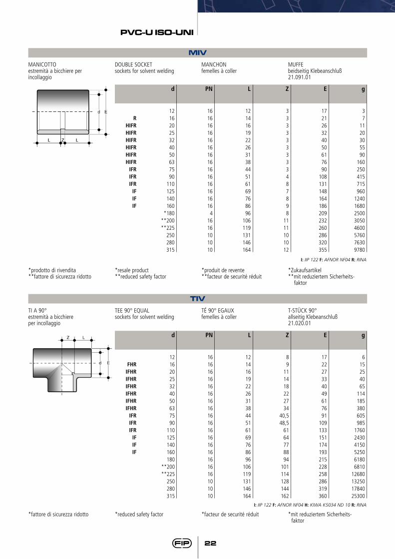
TIVTI A 90°estremità a bicchiereper incollaggio
TEE 90° EQUALsockets for solvent welding
TÉ 90° EGAUXfemelles à coller
T-STÜCK 90°allseitig Klebeanschluß21.020.01
g
615254065
114185380605985
176024304150525061806810
12680132501784025300
Z
89
111418222734
40,548,5
6164778894
101114128144162
E
172227334049617691
109133151174193215228258286319360
L
121416192226313844516169768696
106119131146164
PN
1616161616161616161616161616161616101010
d
12162025324050637590
110125140160180
**200**225
250280315
FHRIFHRIFHRIFHRIFHRIFHRIFHR
IFRIFRIFR
IFIFIF
*fattore di sicurezza ridotto *reduced safety factor *facteur de securité réduit *mit reduziertem Sicherheits- faktor
I: IIP 122 F: AFNOR NF04 H: KIWA K5034 ND 10 R: RINA
MIVMANICOTTOestremità a bicchiere per incollaggio
DOUBLE SOCKETsockets for solvent welding
MANCHONfemelles à coller
MUFFE beidseitig Klebeanschluß21.091.01
g
37
1120305590
160250415715960
12401680250030504600576076309780
Z
333333333487898
1111101012
E
172126324050617690
108131148164186209232260286320355
L
121416192226313844516169768696
106119131146164
PN
16161616161616161616161616164
1616101010
d
12162025324050637590
110125140160
*180**200**225
250280315
RHIFRHIFRHIFRHIFRHIFRHIFR
IFRIFRIFR
IFIFIF
I: IIP 122 F: AFNOR NF04 R: RINA
*prodotto di rivendita**fattore di sicurezza ridotto
*resale product**reduced safety factor
*produit de revente**facteur de securité réduit
*Zukaufsartikel**mit reduziertem Sicherheits-
faktor
23
PVC-U ISO-UNI
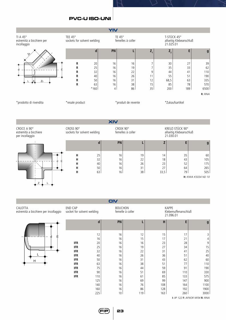
YIVTI A 45° estremità a bicchiere per incollaggio
*prodotto di rivendita
TEE 45°sockets for solvent welding
*resale product
TE 45°femelles à coller
*produit de revente
T-STÜCK 45°allseitig Klebeanschluß21.025.01
*Zukaufsartikel
g
3962
110190335570
6500
Z1
779
11121535
Z2
30354455
68,585
200
E
273341516378
189
L
16192226313886
PN
1616161616164
d
202532405063
*160
RRRRRR
R: RINA
XIVCROCE A 90°estremità a bicchiereper incollaggio
CROSS 90°sockets for solvent welding
CROIX 90°femelles à coller
KREUZ-STÜCK 90°allseitig Klebeanschluß21.030.01
g
60105175265505
Z
14182327
33,5
E
3543526479
L
1922263138
PN
1616161616
d
2532405063
HHHHH
H: KIWA K5034 ND 10
CIVCALOTTAestremità a bicchiere per incollaggio
END CAPsocket for solvent welding
BOUCHONfemelle à coller
KAPPEKlebemuffenanschluß21.096.01
g
349
15254060
110190330575900
110019003000
H
151723273136435159698599
108128163
E
172128344151627791
110133147164192260
L
1215161922263138445161697686
119
PN
161616161616161616161616161610
d
12162025324050637590
110125140160225
IFRIFRIFRIFRIFRIFRIFRIFRIFR
I: IIP 122 F: AFNOR NF04 R: RINA
24
PVC-U ISO-UNI
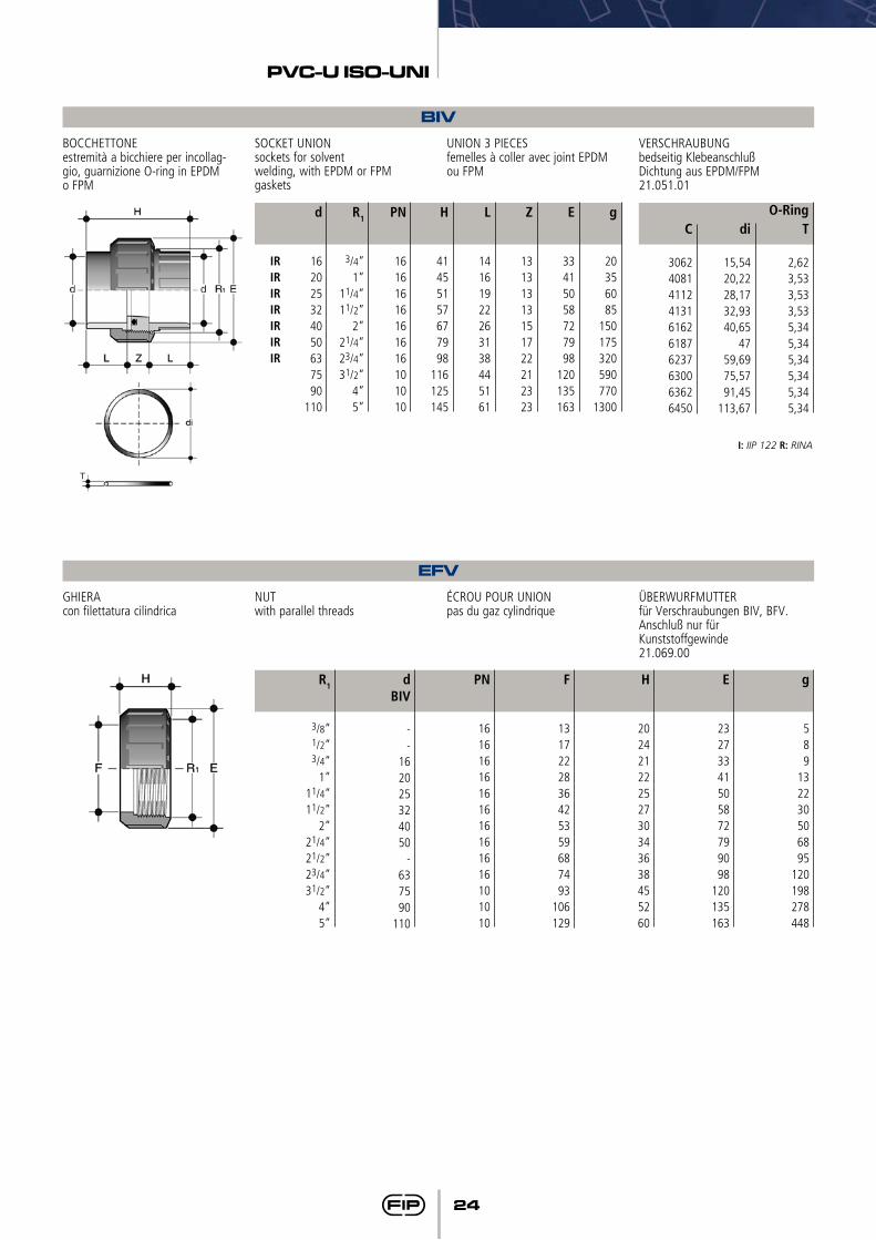
EFVGHIERAcon filettatura cilindrica
NUTwith parallel threads
ÉCROU POUR UNIONpas du gaz cylindrique
ÜBERWURFMUTTERfür Verschraubungen BIV, BFV.Anschluß nur fürKunststoffgewinde21.069.00
g
589
132230506895
120198278448
H
20242122252730343638455260
E
23273341505872799098
120135163
F
1317222836425359687493
106129
PN
16161616161616161616101010
dBIV
--
162025324050
-637590
110
R1
3/8”1/2”3/4”
1”11/4”11/2”
2”21/4”21/2”23/4”31/2”
4”5”
BIVBOCCHETTONEestremità a bicchiere per incollag-gio, guarnizione O-ring in EPDM o FPM
SOCKET UNIONsockets for solventwelding, with EPDM or FPM gaskets
UNION 3 PIECESfemelles à coller avec joint EPDM ou FPM
VERSCHRAUBUNGbedseitig KlebeanschlußDichtung aus EPDM/FPM21.051.01
IRIRIRIRIRIRIR
H
41455157677998
116125145
PN
16161616161616101010
g
20356085
150175320590770
1300
d
162025324050637590
110
R1
3/4”1”
11/4”11/2”
2”21/4”23/4”31/2”
4”5”
L
14161922263138445161
Z
13131313151722212323
E
33415058727998
120135163
C
3062408141124131616261876237630063626450
T
2,623,533,533,535,345,345,345,345,345,34
di
15,5420,2228,1732,9340,65
4759,6975,5791,45
113,67
O-Ring
I: IIP 122 R: RINA
25
PVC-U ISO-UNI
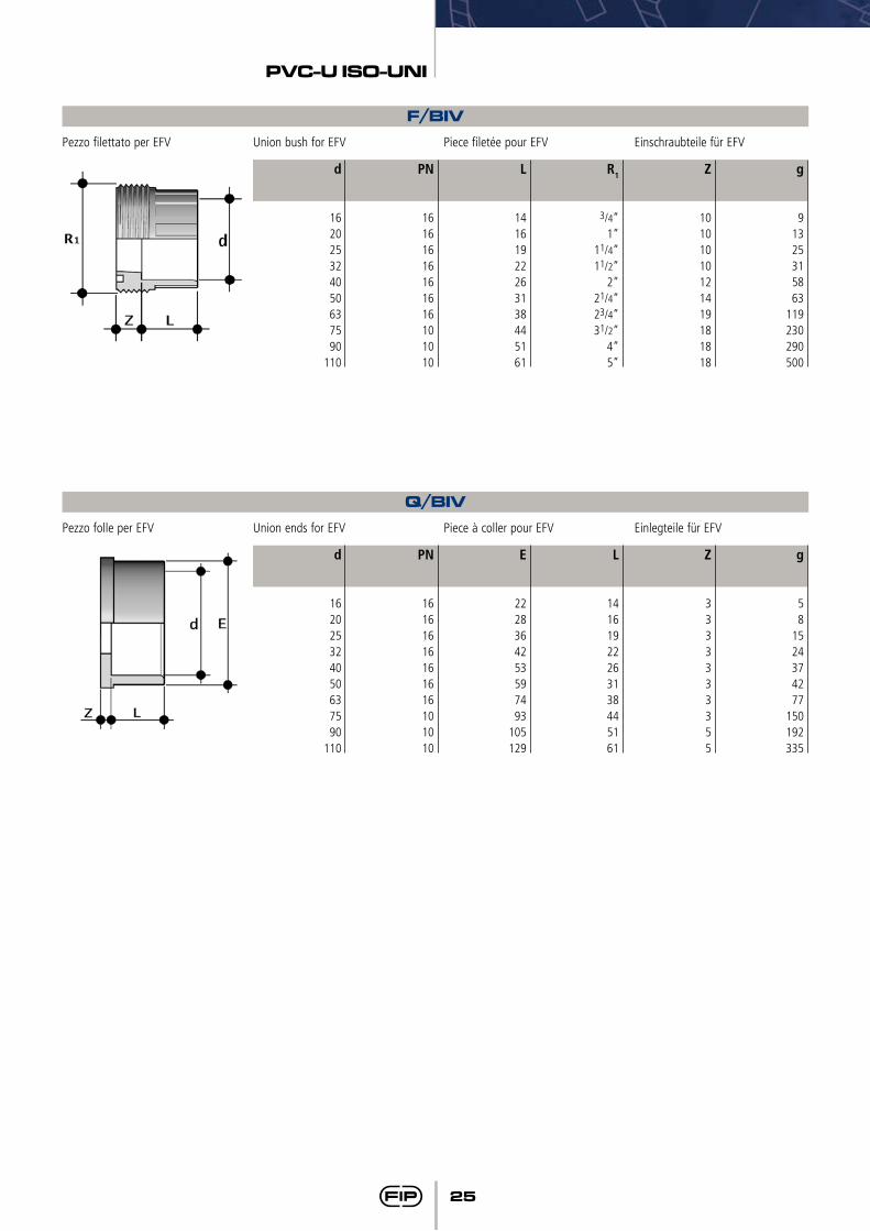
F/BIVPezzo filettato per EFV Union bush for EFV Piece filetée pour EFV Einschraubteile für EFV
g
91325315863
119230290500
R1
3/4”1”
11/4”11/2”
2”21/4”23/4”31/2”
4”5”
Z
10101010121419181818
L
14161922263138445161
PN
16161616161616101010
d
162025324050637590
110
Q/BIVPezzo folle per EFV Union ends for EFV Piece à coller pour EFV Einlegteile für EFV
g
58
1524374277
150192335
L
14161922263138445161
Z
3333333355
E
2228364253597493
105129
PN
16161616161616101010
d
162025324050637590
110
26
PVC-U ISO-UNI
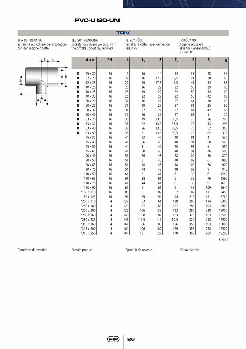
TRIVTI A 90° RIDOTTOestremità a bicchiere per incollaggio con derivazione ridotta
TEE 90° REDUCINGsockets for solvent welding, with the offtake socket d1, reduced
TE 90° RÉDUITfemelles à coller, avec dérivation réduit d1
T-STÜCK 90°Abgang reduziertallseitig Klebeanschluß21.020.01
g
376065
100100105160160165170290295300315530540550580870880900940
15801590161016403450676083009900
120001250014900150001750019200
L1
161619161922161922261922263122263138263138443138445161696387
10688
117.586
106131
Z
1417,517,5
22222227272727
33,533,533,533,5
40404040484848486161616182946186
13384
11783
102127
Z1
1417,517,5
22222227272727
33,533,533,533,5
4040404048484848616161615794
128127132153
150,5126179178
E
334141505050616161617676767691919191
109109109109133133133133187215285285285320320355355355
E1
28283429344230354251364352624150617650617691617691
109131151134193228193258193228285
L
19222226262631313131383838384444444451515151616161618696
129129129146146164164164
PN
1616161616161616161616161616161616161616161616161616161644444444
d x d1
25 x 2032 x 2032 x 2540 x 2040 x 2540 x 3250 x 2050 x 2550 x 3250 x 4063 x 2563 x 3263 x 4063 x 5075 x 3275 x 4075 x 5075 x 6390 x 4090 x 5090 x 6390 x 75
110 x 50110 x 63110 x 75110 x 90
*160 x 110180 x 125
*250 x 110*250 x 160*250 x 200*280 x 160*280 x 225*315 x 160*315 x 200*315 x 250
RRRRRRRRRRRRRR
R: RINA
*prodotto di rivendita *resale product *produit de revente *Zukaufsartikel
27
PVC-U ISO-UNI
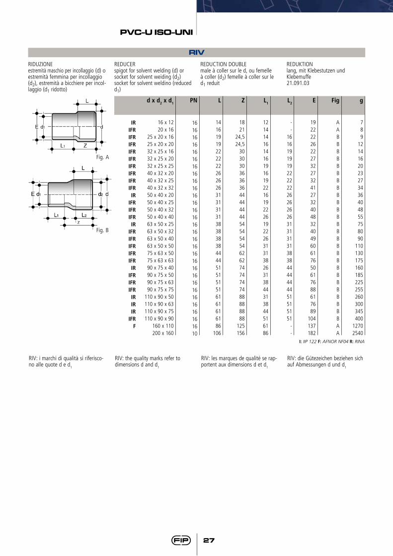
RIVRIDUZIONEestremità maschio per incollaggio (d) o estremità femmina per incollaggio (d2), estremità a bicchiere per incol-laggio (d1 ridotto)
REDUCERspigot for solvent welding (d) or socket for solvent weiding (d2) socket for solvent weldino (reduced d1)
REDUCTION DOUBLEmale à coller sur le d, ou femelle à coller (d2) femelle à coller sur le d1 reduit
REDUKTIONlang, mit Klebestutzen und Klebemuffe21.091.03
g
789
1214162023273436404855758090
110130175160185225255260300345400
12702540
Z
1821
24,524,5
303030363636444444445454545462627474747488888888
125156
L1
121414161416191619221619222619222631313826313844313844516186
L2
--
1616191919222222262626263131313138384444444451515151
--
E
192222262227322732412732404832404960617650617688617689
104137182
Fig
AABBBBBBBBBBBBBBBBBBBBBBBBBBAA
L
1416191922222226262631313131383838384444515151516161616186
106
PN
161616161616161616161616161616161616161616161616161616161610
d x d2 x d1
16 x 1220 x 16
25 x 20 x 1625 x 20 x 2032 x 25 x 1632 x 25 x 2032 x 25 x 2540 x 32 x 2040 x 32 x 2540 x 32 x 3250 x 40 x 2050 x 40 x 2550 x 40 x 3250 x 40 x 4063 x 50 x 2563 x 50 x 3263 x 50 x 4063 x 50 x 5075 x 63 x 5075 x 63 x 6390 x 75 x 4090 x 75 x 5090 x 75 x 6390 x 75 x 75
110 x 90 x 50110 x 90 x 63110 x 90 x 75110 x 90 x 90
160 x 110200 x 160
IRIFRIFRIFRIFRIFRIFRIFRIFRIFRIR
IFRIFRIFRIR
IFRIFRIFRIFRIFRIR
IFRIFRIFRIRIRIR
IFRF
I: IIP 122 F: AFNOR NF04 R: RINA
RIV: i marchi di qualità si riferisco-no alle quote d e d1
RIV: the quality marks refer to dimensions d and d1
RIV: les marques de qualité se rap-portent aux dimensions d et d1
RIV: die Gütezeichen beziehen sich auf Abmessungen d und d1
Fig. A
Fig. B
28
PVC-U ISO-UNI
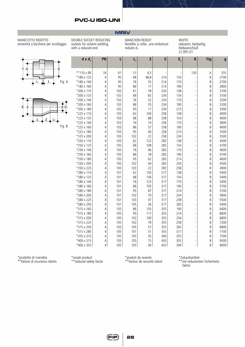
MRIVMANICOTTO RIDOTTOestremità a bicchiere per incollaggio
DOUBLE SOCKET REDUCINGsockets for solvent welding,with a reduced end
MANCHON REDUITfemelles à coller, une emboiture reduite d1
MUFFEreduziert, beidseitigKlebeanschluß21.091.01
g
55527002700280031003100320032003300400040003800400035003500450047004600470046004500490054005400540057005700580055005400640066006800720068007100750095009000
L1
5168768661687686956268768695
1026268768695
1021036268768695
1021031058695
102103105101105105105
Z
4,548,8
35177865523517
1008874574022
1221089678624422
15013612310587704726
135117100795731357540
E
-214214214234234234234234258258258258258258283283283283283283283317317317317317317317317355355355355355355394435435
E1
-154170190138154170190213138154170190214234138154170190214234258138154170190214234258283190214234258283317355355394
K
130--------------------------------------
Fig
ABBBBBBBBBBBBBBBBBBBBBBBBBBBBBBBBBBBBBB
L
61959595
102102102102102103103103103103103105105105105105105105101101101101101101101101105105105105105105105105105
PN
1644444444444444444444444444444444444444
d x d1
**110 x 90*180 x 125*180 x 140*180 x 160*200 x 110*200 x 125*200 x 140*200 x 160*200 x 180*225 x 110*225 x 125*225 x 140*225 x 160*225 x 180*225 x 200*250 x 110*250 x 125*250 x 140*250 x 160*250 x 180*250 x 200*250 x 225*280 x 110*280 x 125*280 x 140*280 x 160*280 x 180*280 x 200*280 x 225*280 x 250*315 x 160*315 x 180*315 x 200*315 x 225*315 x 250*315 x 280*355 x 315*400 x 315*400 x 355
*prodotto di rivendita**fattore di sicurezza ridotto
*resale product**reduced safety factor
*produit de revente**facteur de securité réduit
*Zukaufsartikel**mit reduziertem Sicherheits-
faktor
Fig. A
Fig. B
29
PVC-U ISO-UNI
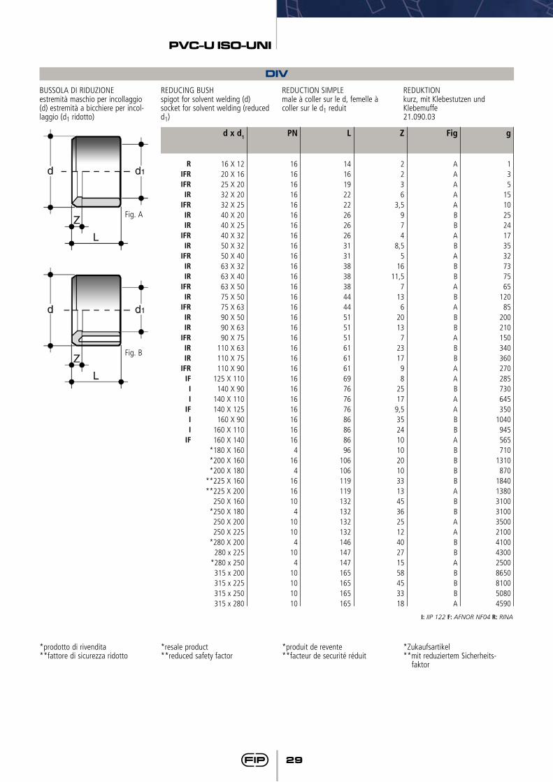
*prodotto di rivendita**fattore di sicurezza ridotto
*resale product**reduced safety factor
*produit de revente**facteur de securité réduit
*Zukaufsartikel**mit reduziertem Sicherheits-
faktor
DIVBUSSOLA DI RIDUZIONEestremità maschio per incollaggio (d) estremità a bicchiere per incol-laggio (d1 ridotto)
REDUCING BUSHspigot for solvent welding (d) socket for solvent welding (reduced d1)
REDUCTION SIMPLEmale à coller sur le d, femelle à coller sur le d1 reduit
REDUKTIONkurz, mit Klebestutzen und Klebemuffe21.090.03
g
135
15102524173532737565
12085
200210150340360270285730645350
1040945565710
1310870
1840138031003100350021004100430025008650810050804590
Z
2236
3,5974
8,55
1611,5
7136
20137
231798
2517
9,535241010201033134536251240271558453318
Fig
AAAAABBABABBABABBABBAABAABBABBBBABBAABB ABBBA
L
1416192222262626313138383844445151516161616976767686868696
106106119119132132132132146147147165165165165
PN
161616161616161616161616161616161616161616161616161616164
164
1616104
10104
104
10101010
d x d1
16 X 1220 X 1625 X 2032 X 2032 X 2540 X 2040 X 2540 X 3250 X 3250 X 4063 X 3263 X 4063 X 5075 X 5075 X 6390 X 5090 X 6390 X 75
110 X 63110 X 75110 X 90
125 X 110140 X 90
140 X 110140 X 125
160 X 90160 X 110160 X 140
*180 X 160*200 X 160*200 X 180
**225 X 160**225 X 200
250 X 160*250 X 180
250 X 200250 X 225
*280 X 200280 x 225
*280 x 250315 x 200315 x 225315 x 250315 x 280
RIFRIFRIR
IFRIRIR
IFRIR
IFRIRIR
IFRIR
IFRIRIR
IFRIRIR
IFRIFII
IFII
IF
I: IIP 122 F: AFNOR NF04 R: RINA
Fig. A
Fig. B
30
PVC-U ISO-UNI
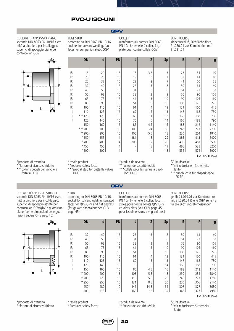
QPVCOLLARE D’APPOGGIO PIANO secondo DIN 8063 PN 10/16 estre-mità a bicchiere per incollaggio, superfici di appoggio piane per controcollari QGV
FLAT STUBaccording to DIN 8063 PN 10/16, sockets for solvent welding, flat faces for companion stubs QGV
COLLET(conformes au normes DIN 8063 PN 10/16) femelle à coller, façe plate pour contre collets QGV
BUNDBUCHSEKlebeanschluß, Dichfläche flach, 21.080.01 zur Kombination mit21.081.01
g
1016254062
105160275445750760790
1140270018405400650052003000
L
16192226313844516169697686
106106184206
--
Z
3,5333333545
115
4,524
5,58
128-
Sp
777889
10101213131416301829261918
E
27334150617690
108131147165165188248230386430486532
F
344150617390
105125150168188188212273254413483538574
PN
1616161616161616161616161616164444
d
2025324050637590
110125125140160200200355400450500
DN
1520253240506580
100110
***125125150
***200**200
*350*400*450*500
IRIRIRIRIRIRIRIRIR
III
*prodotto di rivendita**fattore di sicurezza ridotto***collari speciali per valvole a
farfalla FK-FE
*resale product**reduced safety factor***special stub for butterfly valves
FK-FE
*produit de revente**facteur de securité réduit***collets pour les vanne à papil-
lon: FK-FE
*Zukaufsartikel**mit reduziertem Sicherheits-
faktor***bundbuchse für absperklappe
FK-FE
I: IIP 122 R: RINA
QRVCOLLARE D’APPOGGIO STRIATO secondo DIN 8063 PN 10/16 estre-mità a bicchiere per incol-laggio, superfici di appoggio striate per controcollari QPV/QRV e guarnizioni piane (per le dimensioni delle guar-nizioni vedere QHV pag. 45)
STUBaccording to DIN 8063 PN 10/16, socket for solvent welding, serrated faces for QPV/QRV and flat gaskets (for gasket dimensions see QHV page 45)
COLLET(conformes au normes DIN 8063 PN 10/16) femelle à coller, façe striée pour contre collets QPV/QRV et joints plats (voir QHV page 45 pour les dimensions des garnitures)
BUNDBUCHSEgerillt 21.079.01 zur Kombina-tion mit 21.080.01 (Siehe QHV Seite 45 für die Dichtungsab-messungen
g
4062
105160275445750790
114018401750214036504950
L
263138445161697686
106119131147165
Z
33335455
4,55,55,58,5
14,516
Sp
889
1010121314161825203232
E
50617690
108131147165188230245270307346
F
617390
105125150168188212254273306327377
PN
1616161616161616161616161010
d
4050637590
110125140160200225250280315
DN
3240506580
100110125150
**200**200**250
250300
IRIRIRIRIRIR
III
I: IIP 122 R: RINA
*prodotto di rivendita**fattore di sicurezza ridotto
*resale product**reduced safety factor
*produit de revente**facteur de securité réduit
*Zukaufsartikel**mit reduziertem Sicherheits-
faktor
31
PVC-U ISO-UNI
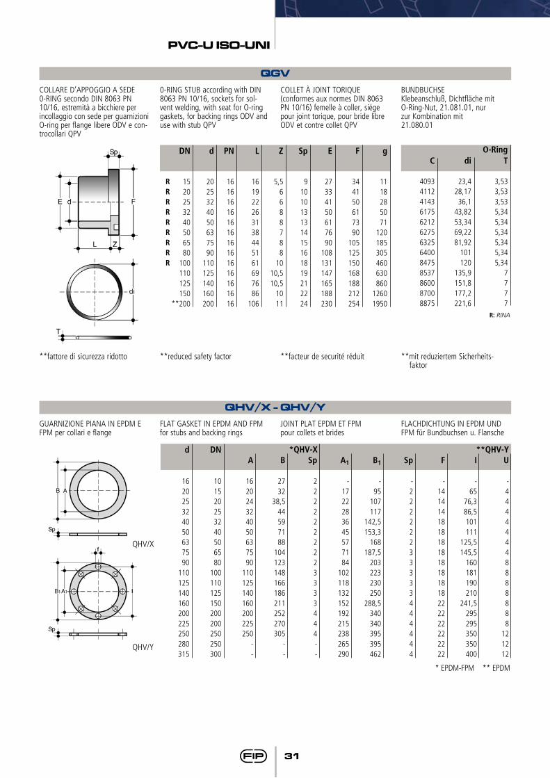
QGVCOLLARE D’APPOGGIO A SEDE 0-RING secondo DIN 8063 PN 10/16, estremità a bicchiere per incollaggio con sede per guarnizioni O-ring per flange libere ODV e con-trocollari QPV
0-RING STUB according with DIN 8063 PN 10/16, sockets for sol-vent welding, with seat for O-ring gaskets, for backing rings ODV and use with stub QPV
COLLET À JOINT TORIQUE(conformes aux normes DIN 8063 PN 10/16) femelle à coller, siége pour joint torique, pour bride libre ODV et contre collet QPV
BUNDBUCHSEKlebeanschluß, Dichtfläche mitO-Ring-Nut, 21.081.01, nurzur Kombination mit21.080.01
RRRRRRRRR
L
161922263138445161697686
106
PN
16161616161616161616161616
g
1118285071
120185305460630860
12601950
DN
1520253240506580
100110125150
**200
d
2025324050637590
110125140160200
Z
5,56688788
1010,510,5
1011
Sp
9101013131415161819212224
E
27334150617690
108131147165188230
F
344150617390
105125150168188212254
C
4093411241436175621262756325640084758537860087008875
T
3,533,533,535,345,345,345,345,345,34
7777
di
23,428,1736,1
43,8253,3469,2281,92
101120
135,9151,8177,2221,6
O-Ring
**fattore di sicurezza ridotto **reduced safety factor **facteur de securité réduit **mit reduziertem Sicherheits- faktor
R: RINA
QHV/X - QHV/YGUARNIZIONE PIANA IN EPDM E FPM per collari e flange
FLAT GASKET IN EPDM AND FPM for stubs and backing rings
JOINT PLAT EPDM ET FPMpour collets et brides
FLACHDICHTUNG IN EPDM UND FPM für Bundbuchsen u. Flansche
F
-1414141818181818181818222222222222
U
-44444448888888
121212
B
2732
38,544597188
104123148166186211252270305
--
Sp
2222222223333444--
A1
-1722283645577184
102118132152192215238265290
B1
-95
107117
142,5153,3
168187,5
203223230250
288,5340340395395462
Sp
-22222233333444444
I
-65
76,386,5101111
125,5145,5
160181190210
241,5295295350350400
A
162024324050637590
110125140160200225250
--
DN
101520253240506580
100110125150200200250250300
d
162025324050637590
110125140160200225250280315
QHV/X
QHV/Y
*QHV-X **QHV-Y
* EPDM-FPM ** EPDM
32
PVC-U ISO-UNI
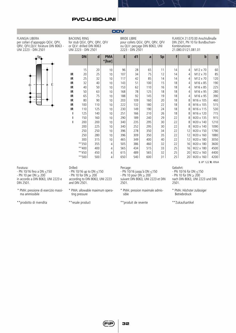
ODVFLANGIA LIBERAper collari d’appoggio QGV, QPV, QRV, QFV,QLV: forature DIN 8063 - UNI 2223 - DIN 2501
BACKING RINGfor stub QGV, QPV, QRV, QFVor QLV: drilled DIN 8063UNI 2223 - DIN 2501
BRIDE LIBRE pour collets QGV, QPV, QRV, QFV ou QLV: perçage DIN 8063, UNI 2223 - DIN 2501
FLANSCH 21.070.00 Anschlußmaße DIN 2501, PN 10 für Bundbuchsen-Kombinationen21.080.01/21.081.01
g
6085
120190225280390460515530715915
121010901790188030503600450044004200
E
96107117143153168188203222230251290340340396396465505565615650
d1
28344251627892
109132149166189235252278309349386434489540
a
657585
100110125145160180190210240295295350350400460515565600
Sp
111214151618192022242629303034354032333231
f
141414181818181818181822222222222222252525
U
44444448888888
12121216162020
b
M12 x 70M12 x 70M12 x 70M16 x 85M16 x 85M16 x 95M16 x 95
M16 x 105M16 x 105M16 x 115M16 x 120M20 x 135M20 x 140M20 x 140M20 x 150M20 x 160M20 x 180M20 x 180M22 x 180M22 x 160M20 x 160
PMA*[bar]
10101010101010101010101010101010104444
d
2025324050637590
110125140160200225250280315355400450500
DN
1520253240506580
100110125150200200250250300
**350**400**450**500
IRIRIRIRIRIRIRIRIR
III
**prodotto di rivendita
Foratura:- PN 10/16 fino a DN <150- PN 10 per DN > 200 in accordo a DIN 8063, UNI 2223 e DIN 2501.
**resale product
Drilled:- PN 10/16 up to DN <150- PN 10 for DN > 200according to DIN 8063, UNI 2223 and DIN 2501.
**produit de revente
Percage:- PN 10/16 jusqu’à DN <150- PN 10 pour DN > 200suivant DIN 8063, UNI 2223 et DIN 2501.
**Zukaufsartikel
Gebohrt: - PN 10/16 für DN <150 - PN 10 für DN > 200 nach DIN 8063, UNI 2223 und DIN 2501.
I: IIP 122 R: RINA
* PMA: pressione di esercizio massi-ma ammissibile
* PMA: allowable maximum opera-ting pressure
* PMA: pression maximale admis-sible
* PMA: Höchster zulässiger Betriebrdruck
33
PVC-U ISO-UNI
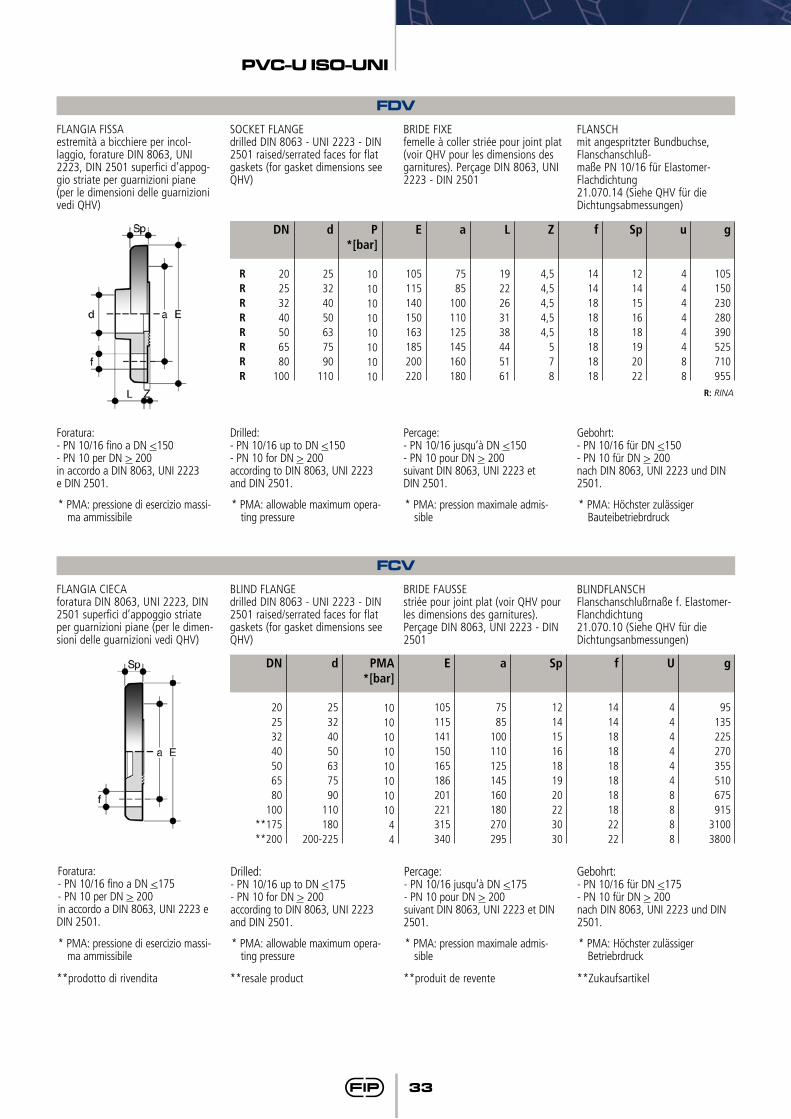
FDVFLANGIA FISSAestremità a bicchiere per incol-laggio, forature DIN 8063, UNI 2223, DIN 2501 superfici d’appog-gio striate per guarnizioni piane (per le dimensioni delle guarnizioni vedi QHV)
SOCKET FLANGEdrilled DIN 8063 - UNI 2223 - DIN 2501 raised/serrated faces for flat gaskets (for gasket dimensions see QHV)
BRIDE FIXEfemelle à coller striée pour joint plat (voir QHV pour les dimensions des garnitures). Perçage DIN 8063, UNI 2223 - DIN 2501
FLANSCHmit angespritzter Bundbuchse, Flanschanschluß-maße PN 10/16 für Elastomer-Flachdichtung21.070.14 (Siehe QHV für die Dichtungsabmessungen)
g
105150230280390525710955
E
105115140150163185200220
a
7585
100110125145160180
L
1922263138445161
Z
4,54,54,54,54,5
578
f
1414181818181818
Sp
1214151618192022
u
44444488
P*[bar]
1010101010101010
d
25324050637590
110
DN
20253240506580
100
RRRRRRRR
Foratura:- PN 10/16 fino a DN <150- PN 10 per DN > 200 in accordo a DIN 8063, UNI 2223e DIN 2501.
Drilled:- PN 10/16 up to DN <150- PN 10 for DN > 200according to DIN 8063, UNI 2223and DIN 2501.
Percage:- PN 10/16 jusqu’à DN <150- PN 10 pour DN > 200suivant DIN 8063, UNI 2223 etDIN 2501.
Gebohrt:- PN 10/16 für DN <150- PN 10 für DN > 200nach DIN 8063, UNI 2223 und DIN 2501.
R: RINA
FCVFLANGIA CIECAforatura DIN 8063, UNI 2223, DIN 2501 superfici d’appoggio striate per guarnizioni piane (per le dimen-sioni delle guarnizioni vedi QHV)
BLIND FLANGEdrilled DIN 8063 - UNI 2223 - DIN 2501 raised/serrated faces for flat gaskets (for gasket dimensions see QHV)
BRIDE FAUSSEstriée pour joint plat (voir QHV pour les dimensions des garnitures). Perçage DIN 8063, UNI 2223 - DIN 2501
BLINDFLANSCHFlanschanschlußrnaße f. Elastomer-Flanchdichtung21.070.10 (Siehe QHV für dieDichtungsanbmessungen)
g
95135225270355510675915
31003800
E
105115141150165186201221315340
a
7585
100110125145160180270295
Sp
12141516181920223030
f
14141818181818182222
U
4444448888
PMA*[bar]
101010101010101044
d
25324050637590
110180
200-225
DN
20253240506580
100**175**200
Foratura:- PN 10/16 fino a DN <175- PN 10 per DN > 200 in accordo a DIN 8063, UNI 2223 e DIN 2501.
Drilled:- PN 10/16 up to DN <175- PN 10 for DN > 200according to DIN 8063, UNI 2223 and DIN 2501.
Percage:- PN 10/16 jusqu’à DN <175- PN 10 pour DN > 200suivant DIN 8063, UNI 2223 et DIN 2501.
Gebohrt: - PN 10/16 für DN <175 - PN 10 für DN > 200 nach DIN 8063, UNI 2223 und DIN 2501.
**prodotto di rivendita **resale product **produit de revente **Zukaufsartikel
* PMA: pressione di esercizio massi-ma ammissibile
* PMA: pressione di esercizio massi-ma ammissibile
* PMA: allowable maximum opera-ting pressure
* PMA: allowable maximum opera-ting pressure
* PMA: pression maximale admis-sible
* PMA: pression maximale admis-sible
* PMA: Höchster zulässiger Bauteibetriebrdruck
* PMA: Höchster zulässiger Betriebrdruck

34
PVC-U ISO-UNI
ZIKMSUPPORTO PER TUBI in PP
PP SUPPORT CLIP SUPPORT AUTO-SERRANTen PP pour tubes thermoplastiques
ROHRKLEMME aus PP
l
162025324060637590
125140155180200
h
3338445160718497
113134151167190211
b
1814141516171819202325273033
a
2633414958688396
113139158177210237
d
*16*20*25*32*40*50*63*75*90
*110*125*140*160*180
*prodotto di rivendita *resale product *produit de revente *Zukaufsartikel
DSMDistanziali in PP per supporti ZIKM PP distance plates for pipe support
clips ZIKMPièce de distance en PP pour collier auto serrant ZIKM
PP Distanzhalter für Rohrklemme ZIKM
Master
12080504040
C
141717
22,534,5
D
88888
E
44444
Pack.
2010101010
B
1617181920
A
3341516476
d
3240506375
AIVPORTAGOMMA estremità maschio per incollaggio
HOSE ADAPTORspigot for solvent welding
DOUILLE CANNELEEmale à coller
DRUCKSCHLAUCHTÙLLEmit Klebstutzen und zyl.Schlauchtülle 21.096.04
g
61217264078
113170
H
5660678197
104111123
L
1214161922263138
PN
1616161616161616
d x P2 x P1
12 x 14 x 1216 x 18 x 1620 x 22 x 2025 x 27 x 2532 x 32 x 3040 x 42 x 4050 x 52 x 5063 x 64 x 60
Raccordi di passaggioFittings adaptor seriesRaccords serie de passageÜbergangsfittings
ISO-BSP

38
PVC-U ISO-BSP
I dati del presente prospetto sono forniti in buona fede. La FIP non si assume alcu-na responsabilità su quei dati non diret-tamente derivati da norme internazionali. La FIP si riserva di apportarvi qualsiasi modifica.
The data given in this leaflet are offered in good faith. No liability can be accepted concerning technical data that are not directly covered by recognized interna-tional standards. FIP reserves the right to carry out any modification to the products shown in this Ieaflet.
Les données contenues dans cette brochure sont fournies en bonne foi. FIP n’assume aucune responsabilité pour les données qui ne dérivent pas directement des normes internationa-les. FIP garde le droit d’apporter toute modification aux produits présentés dans cette brochure.
Alle Daten dieser Druckschrift wurden nach bestem Wissen angegeben, jedoch besteht keine Verbindlichkeit, sofern sie nicht direkt internationalen Normen entnommen wurden. Die Än-derung von Maßen oder Ausführungen bleibt FIP vorbehalten.
39
PVC-U ISO-BSP
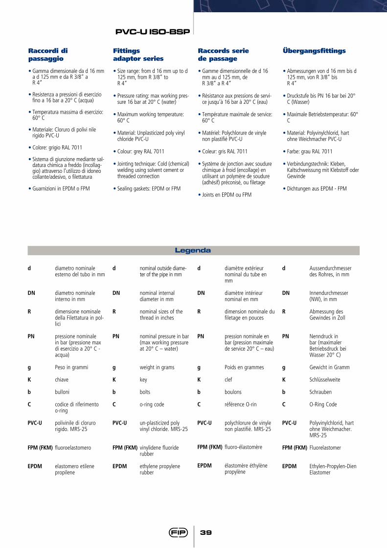
•Gamma dimensionale da d 16 mm a d 125 mm e da R 3/8” a
R 4”
•Resistenza a pressioni di esercizio fino a 16 bar a 20° C (acqua)
•Temperatura massima di esercizio: 60° C
•Materiale: Cloruro di polivi nile rigido PVC-U
•Colore: grigio RAL 7011
•Sistema di giunzione mediante sal-datura chimica a freddo (incollag-gio) attraverso l’utilizzo di idoneo collante/adesivo, o filettatura
•Guarnizioni in EPDM o FPM
•Size range: from d 16 mm up to d 125 mm, from R 3/8” to
R 4”
•Pressure rating: max working pres-sure 16 bar at 20° C (water)
•Maximum working temperature: 60° C
•Material: Unplasticized poly vinyl chloride PVC-U
•Colour: grey RAL 7011
•Jointing technique: Cold (chemical) welding using solvent cement or threaded connection
•Sealing gaskets: EPDM or FPM
•Gamme dimensionnelle de d 16 mm au d 125 mm, de
R 3/8” a R 4”
•Résistance aux pressions de servi-ce jusqu’à 16 bar à 20° C (eau)
•Température maximale de service: 60° C
•Matériel: Polychlorure de vinyle non plastifié PVC-U
•Coleur: gris RAL 7011
•Système de jonction avec soudure chimique à froid (encollage) en utilisant un polymère de soudure (adhésif) préconisé, ou filetage
•Joints en EPDM ou FPM
•Abmessungen von d 16 mm bis d 125 mm, von R 3/8” bis
R 4”
•Druckstufe bis PN 16 bar bei 20° C (Wasser)
•Maximale Betriebstemperatur: 60° C
•Material: Polyvinylchlorid, hart ohne Weichmacher PVC-U
•Farbe: grau RAL 7011
•Verbindungstechnik: Kleben, Kaltschweissung mit Klebstoff oder Gewinde
•Dichtungen aus EPDM - FPM
Raccordi di passaggio
Fittingsadaptor series
ÜbergangsfittingsRaccords seriede passage
Legenda
d diametro nominale esterno del tubo in mm
DN diametro nominale interno in mm
R dimensione nominale della Filettatura in pol-lici
PN pressione nominale in bar (pressione max di esercizio a 20° C - acqua)
g Peso in grammi
K chiave
b bulloni
C codice di riferimento o-ring
PVC-U polivinile di cloruro rigido. MRS-25
FPM (FKM) fluoroelastomero
EPDM elastomero etilene propilene
d nominal outside diame-ter of the pipe in mm
DN nominal internal diameter in mm
R nominal sizes of the thread in inches
PN nominal pressure in bar (max working pressure at 20° C – water)
g weight in grams
K key
b bolts
C o-ring code
PVC-U un-plasticized poly vinyl chloride. MRS-25
FPM (FKM) vinylidene fluoride rubber
EPDM ethylene propylene rubber
d diamètre extérieur nominal du tube en mm
DN diamètre intérieur nominal en mm
R dimension nominale du filetage en pouces
PN pression nominale en bar (pression maximale de service 20° C – eau)
g Poids en grammes
K clef
b boulons
C référence O-rin
PVC-U polychlorure de vinyle non plastifié. MRS-25
FPM (FKM) fluoro-élastomère
EPDM élastomère éthylène propylène
d Aussendurchmesser des Rohres, in mm
DN Innendurchmesser (NW), in mm
R Abmessung des Gewindes in Zoll
PN Nenndruck in bar (maximaler Betriebsdruck bei Wasser 20° C)
g Gewicht in Gramm
K Schlüsselweite
b Schrauben
C O-Ring Code
PVC-U Polyvinylchlorid, hart ohne Weichmacher. MRS-25
FPM (FKM) Fluorelastomer
EPDM Ethylen-Propylen-Dien Elastomer
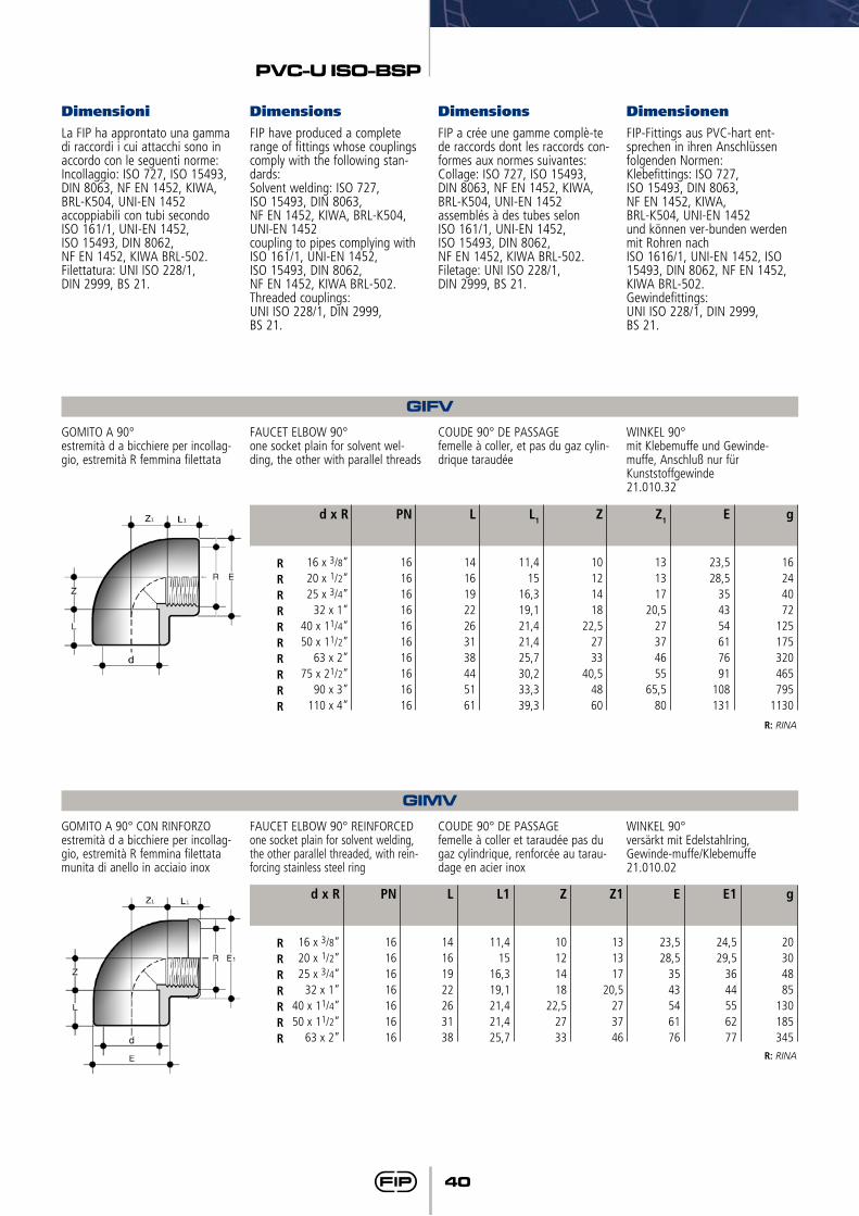
40
PVC-U ISO-BSP
GIFV
GIMV
GOMITO A 90°estremità d a bicchiere per incollag-gio, estremità R femmina filettata
GOMITO A 90° CON RINFORZOestremità d a bicchiere per incollag-gio, estremità R femmina filettata munita di anello in acciaio inox
FAUCET ELBOW 90°one socket plain for solvent wel-ding, the other with parallel threads
FAUCET ELBOW 90° REINFORCEDone socket plain for solvent welding, the other parallel threaded, with rein-forcing stainless steel ring
COUDE 90° DE PASSAGEfemelle à coller, et pas du gaz cylin-drique taraudée
COUDE 90° DE PASSAGEfemelle à coller et taraudée pas du gaz cylindrique, renforcée au tarau-dage en acier inox
WINKEL 90°mit Klebemuffe und Gewinde-muffe, Anschluß nur für Kunststoffgewinde21.010.32
WINKEL 90°versärkt mit Edelstahlring,Gewinde-muffe/Klebemuffe21.010.02
g
16244072
125175320465795
1130
g
20304885
130185345
L1
11,415
16,319,121,421,425,730,233,339,3
L1
11,415
16,319,121,421,425,7
Z
10121418
22,52733
40,54860
Z
10121418
22,52733
Z1
131317
20,527374655
65,580
Z1
131317
20,5273746
E
23,528,5
354354617691
108131
E
23,528,5
3543546176
E1
24,529,5
3644556277
L
14161922263138445161
L
14161922263138
PN
16161616161616161616
PN
16161616161616
d x R
16 x 3/8”20 x 1/2”25 x 3/4”
32 x 1”40 x 11/4”50 x 11/2”
63 x 2”75 x 21/2”
90 x 3”110 x 4”
d x R
16 x 3/8”20 x 1/2”25 x 3/4”
32 x 1”40 x 11/4”50 x 11/2”
63 x 2”
RRRRRRRRRR
RRRRRRR
R: RINA
R: RINA
Dimensioni Dimensions Dimensions DimensionenLa FIP ha approntato una gamma di raccordi i cui attacchi sono in accordo con le seguenti norme:Incollaggio: ISO 727, ISO 15493, DIN 8063, NF EN 1452, KIWA, BRL-K504, UNI-EN 1452 accoppiabili con tubi secondo ISO 161/1, UNI-EN 1452, ISO 15493, DIN 8062, NF EN 1452, KIWA BRL-502. Filettatura: UNI ISO 228/1, DIN 2999, BS 21.
FIP have produced a complete range of fittings whose couplings comply with the following stan-dards:Solvent welding: ISO 727, ISO 15493, DIN 8063, NF EN 1452, KIWA, BRL-K504, UNI-EN 1452 coupling to pipes complying withISO 161/1, UNI-EN 1452, ISO 15493, DIN 8062, NF EN 1452, KIWA BRL-502.Threaded couplings: UNI ISO 228/1, DIN 2999, BS 21.
FIP a crée une gamme complè-te de raccords dont les raccords con-formes aux normes suivantes:Collage: ISO 727, ISO 15493, DIN 8063, NF EN 1452, KIWA, BRL-K504, UNI-EN 1452 assemblés à des tubes selon ISO 161/1, UNI-EN 1452, ISO 15493, DIN 8062, NF EN 1452, KIWA BRL-502. Filetage: UNI ISO 228/1, DIN 2999, BS 21.
FIP-Fittings aus PVC-hart ent-sprechen in ihren Anschlüssen folgenden Normen:Klebefittings: ISO 727, ISO 15493, DIN 8063, NF EN 1452, KIWA, BRL-K504, UNI-EN 1452 und können ver-bunden werden mit Rohren nach ISO 1616/1, UNI-EN 1452, ISO 15493, DIN 8062, NF EN 1452, KIWA BRL-502.Gewindefittings: UNI ISO 228/1, DIN 2999, BS 21.
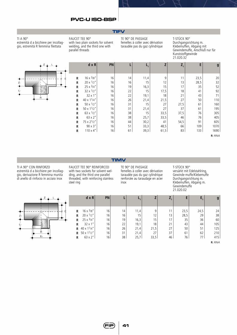
41
PVC-U ISO-BSP
TIFV
TIMV
TI A 90°estremità d a bicchiere per incollag-gio, estremità R femmina filettata
TI A 90° CON RINFORZOestremità d a bicchiere per incollag-gio, derivazione R femmina munita di anello di rinforzo in acciaio inox
FAUCET TEE 90°with two plain sockets for solvent welding, and the third one with parallel threads
FAUCET TEE 90° REINFORCEDwith two sockets for solvent wel-ding, and the third one parallel threaded, with reinforcing stainless steel ring
TE 90° DE PASSAGEfemelles à coller avec dérivation taraudée pas du gaz cylindrique
TE 90° DE PASSAGEfemelles à coller avec dèrivation taraudée pas du gaz cylindrique renforcée au taraudage en acier inox
T-STÜCK 90°Durchgangsrichtung m. Klebemuffen, Abgang mit Gewindemuffe, Anschluß nur für Kunststoffgewinde21.020.32
T-STÜCK 90°versärkt mit Edelstahlring,Gewinde-muffe/Klebemuffe Durchgangsrichtung m. Klebemuffen, Abgang m. Gewindemuffe21.020.02
g
2032529271
110160195305405605
10701690
g
243860
105125210415
L1
11,415
16,315
19,121,4
1521,4
1525,730,233,339,3
L1
11,415
16,319,121,421,425,7
Z
91215
17,518
21,52727
33,533,5
4148,561,5
Z
9121518
21,527
33,5
Z1
111317182127
27,537
37,546
54,56683
Z1
11131721273746
E
23,528,5
354143506161767691
109133
E
23,528,5
3543506176
E1
24,5293644516277
L
14161922222631313838445161
L
14161922263138
PN
16161616161616161616161616
PN
16161616161616
d x R
16 x 3/8”20 x 1/2”25 x 3/4”32 x 1/2”
32 x 1”40 x 11/4”
50 x 1/2”50 x 11/2”
63 x 1/2”63 x 2”
75 x 21/2”90 x 3”
110 x 4”
d x R
16 x 3/8”20 x 1/2”25 x 3/4”
32 x 1”40 x 11/4”50 x 11/2”
63 x 2”
RRRRRRRRRRRRR
RRRRRRR
R: RINA
R: RINA
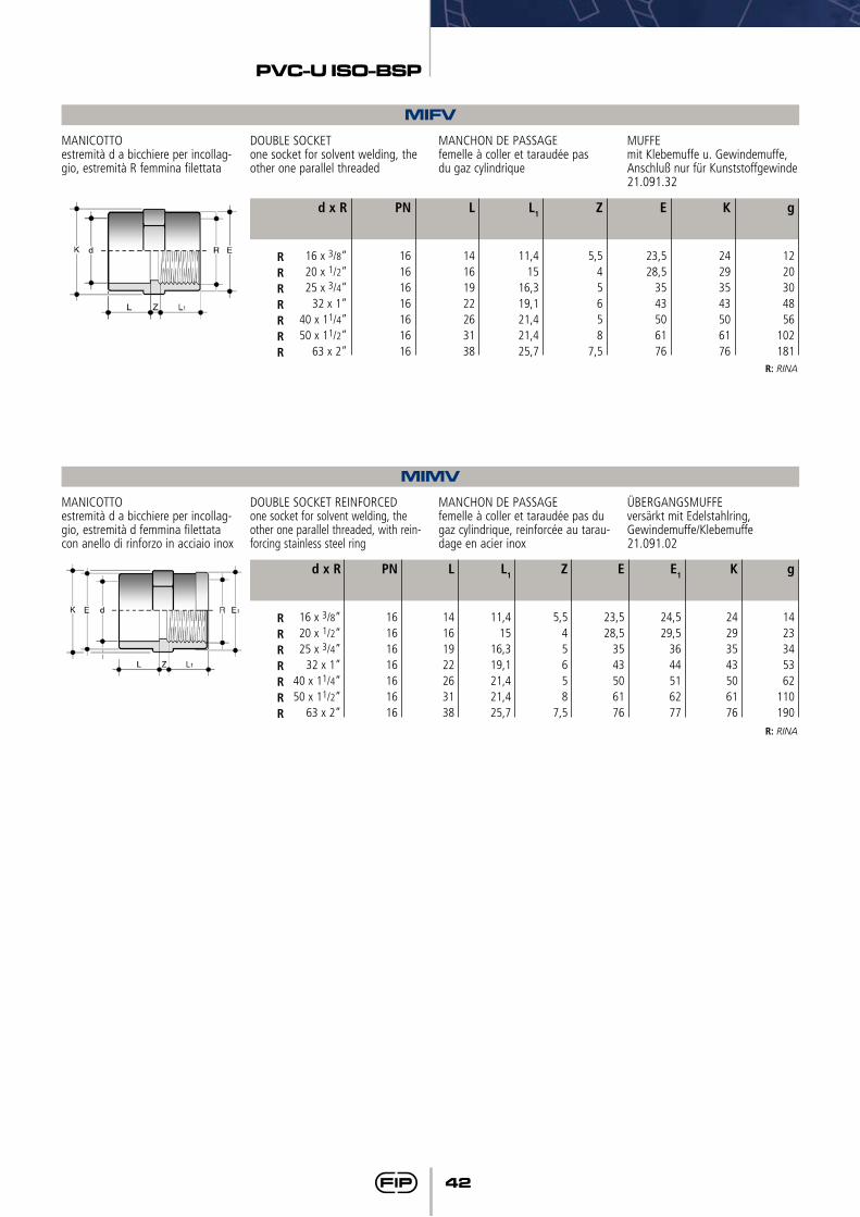
42
PVC-U ISO-BSP
MIFV
MIMV
MANICOTTOestremità d a bicchiere per incollag-gio, estremità R femmina filettata
MANICOTTOestremità d a bicchiere per incollag-gio, estremità d femmina filettata con anello di rinforzo in acciaio inox
DOUBLE SOCKETone socket for solvent welding, the other one parallel threaded
DOUBLE SOCKET REINFORCEDone socket for solvent welding, the other one parallel threaded, with rein-forcing stainless steel ring
MANCHON DE PASSAGEfemelle à coller et taraudée pasdu gaz cylindrique
MANCHON DE PASSAGEfemelle à coller et taraudée pas du gaz cylindrique, reinforcée au tarau-dage en acier inox
MUFFEmit Klebemuffe u. Gewindemuffe, Anschluß nur für Kunststoffgewinde21.091.32
ÜBERGANGSMUFFEversärkt mit Edelstahlring, Gewindemuffe/Klebemuffe21.091.02
g
1220304856
102181
g
1423345362
110190
L1
11,415
16,319,121,421,425,7
L1
11,415
16,319,121,421,425,7
Z
5,545658
7,5
Z
5,545658
7,5
E
23,528,5
3543506176
E
23,528,5
3543506176
K
24293543506176
K
24293543506176
E1
24,529,5
3644516277
L
14161922263138
L
14161922263138
PN
16161616161616
PN
16161616161616
d x R
16 x 3/8”20 x 1/2”25 x 3/4”
32 x 1”40 x 11/4”50 x 11/2”
63 x 2”
d x R
16 x 3/8”20 x 1/2”25 x 3/4”
32 x 1”40 x 11/4”50 x 11/2”
63 x 2”
RRRRRRR
RRRRRRR
R: RINA
R: RINA
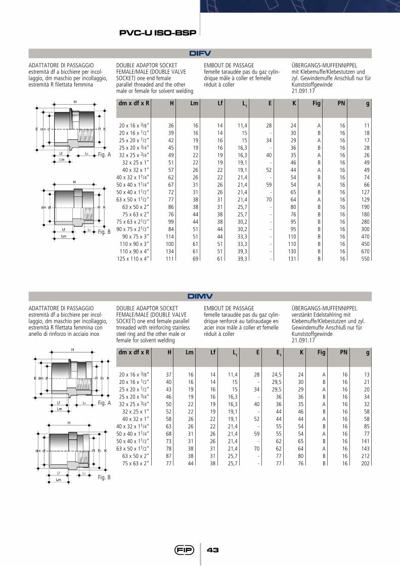
43
PVC-U ISO-BSP
DIFVADATTATORE Dl PASSAGGIOestremità df a bicchiere per incol-laggio, dm maschio per incollaggio, estremità R filettata femmina
DOUBLE ADAPTOR SOCKET FEMALE/MALE (DOUBLE VALVE SOCKET) one end female parallel threaded and the other male or female for solvent welding
EMBOUT DE PASSAGEfemelle taraudée pas du gaz cylin-drique mâle à coller et femelle réduit à coller
ÜBERGANGS-MUFFENNIPPELmit Klebemuffe/Klebestutzen und zyl. Gewindemuffe Anschluß nur für Kunststoffgewinde21.091.17
g
111817282649497466
127129190180280300470450670550
Lf
14141616191922222626313138384444515161
L1
11,41515
16,316,319,119,121,421,421,421,425,725,730,230,233,333,339,339,3
E
28-
34-
40-
52-
59-
70--------
K
243029363546445454656480769595
110110130131
Fig
ABABABABABABBBBBBBB
PN
16161616161616161616161616161616161616
Lm
16161919222226263131383844445151616169
H
363942454951576267727786769984
114100134111
dm x df x R
20 x 16 x 3/8”20 x 16 x 1/2”25 x 20 x 1/2”25 x 20 x 3/4”32 x 25 x 3/4”
32 x 25 x 1”40 x 32 x 1”
40 x 32 x 11/4”50 x 40 x 11/4”50 x 40 x 11/2”63 x 50 x 11/2”
63 x 50 x 2”75 x 63 x 2”
75 x 63 x 21/2”90 x 75 x 21/2”
90 x 75 x 3”110 x 90 x 3”110 x 90 x 4”
125 x 110 x 4”
Fig. A
Fig. B
DIMVADATTATORE Dl PASSAGGIOestremità df a bicchiere per incol-laggio, dm maschio per incollaggio, estremità R filettata femmina con anello di rinforzo in acciaio inox
DOUBLE ADAPTOR SOCKET FEMALE/MALE (DOUBLE VALVE SOCKET) one end female parallel tnreaded with reinforcing stainless steel ring and the other male or female for solvent welding
EMBOUT DE PASSAGEfemelle taraudée pas du gaz cylin-drique renforcé au tatìraudage en acier inox mâle à coller et femelle réduit à coller
ÜBERGANGS-MUFFENNIPPELverstänkt Edelstahlring mitKlebemuffe/Klebestutzen und zyl.Gewindemuffe Anschluß nur für Kunststoffgewinde21.091.17
g
132120343258588577
141143212202
Lf
14141616191922222626313138
L1
11,41515
16,316,319,119,121,421,421,421,425,725,7
E
28-
34-
40-
52-
59-
70--
E1
24,529,529,5
36364444555562627777
K
24302936354644545465648076
Fig
ABABABABABABB
PN
16161616161616161616161616
Lm
16161919222226263131383844
H
37404346505258636873788777
dm x df x R
20 x 16 x 3/8”20 x 16 x 1/2”25 x 20 x 1/2”25 x 20 x 3/4”32 x 25 x 3/4”
32 x 25 x 1”40 x 32 x 1”
40 x 32 x 11/4”50 x 40 x 11/4”50 x 40 x 11/2”63 x 50 x 11/2”
63 x 50 x 2”75 x 63 x 2”
Fig. A
Fig. B
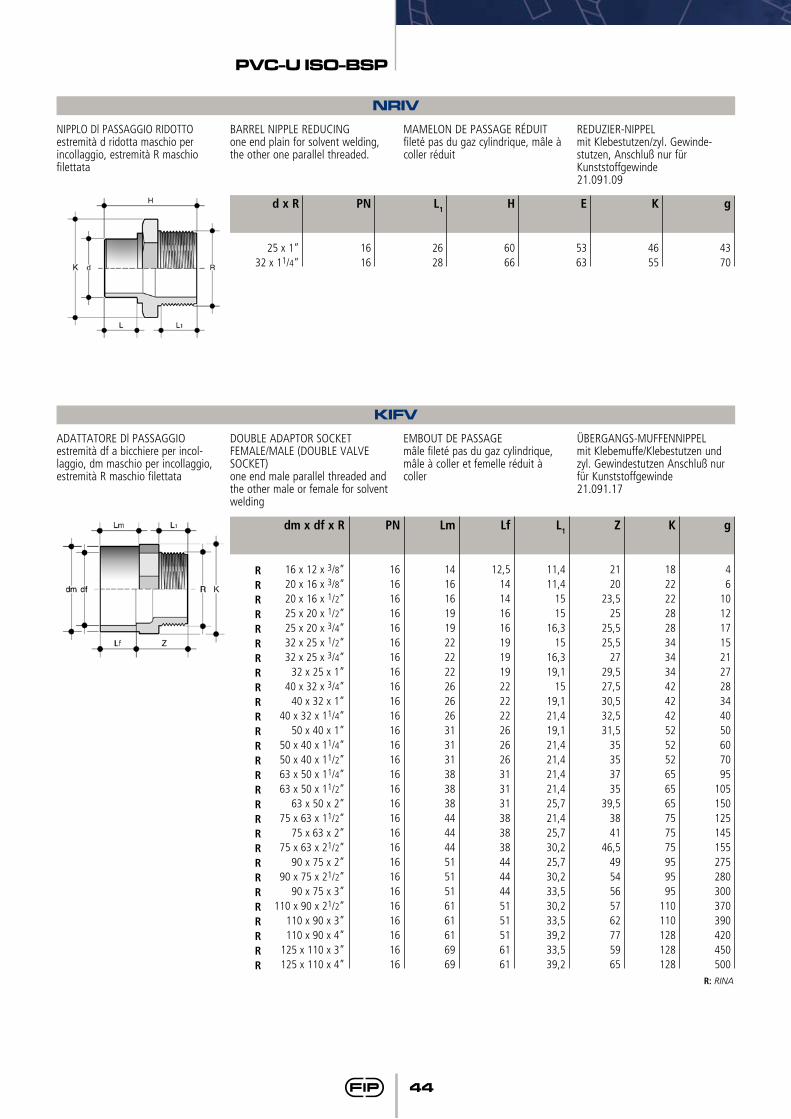
44
PVC-U ISO-BSP
KIFVADATTATORE Dl PASSAGGIOestremità df a bicchiere per incol-laggio, dm maschio per incollaggio, estremità R maschio filettata
DOUBLE ADAPTOR SOCKET FEMALE/MALE (DOUBLE VALVE SOCKET)one end male parallel threaded and the other male or female for solvent welding
EMBOUT DE PASSAGEmâle fileté pas du gaz cylindrique, mâle à coller et femelle réduit à coller
ÜBERGANGS-MUFFENNIPPELmit Klebemuffe/Klebestutzen und zyl. Gewindestutzen Anschluß nur für Kunststoffgewinde21.091.17
g
46
10121715212728344050607095
105150125145155275280300370390420450500
Lf
12,5141416161919192222222626263131313838384444445151516161
L1
11,411,4
1515
16,315
16,319,1
1519,121,419,121,421,421,421,425,721,425,730,225,730,233,530,233,539,233,539,2
Z
2120
23,525
25,525,5
2729,527,530,532,531,5
35353735
39,53841
46,54954565762775965
K
1822222828343434424242525252656565757575959595
110110128128128
Lm
14161619192222222626263131313838384444445151516161616969
PN
16161616161616161616161616161616161616161616161616161616
dm x df x R
16 x 12 x 3/8”20 x 16 x 3/8”20 x 16 x 1/2”25 x 20 x 1/2”25 x 20 x 3/4”32 x 25 x 1/2”32 x 25 x 3/4”
32 x 25 x 1”40 x 32 x 3/4”
40 x 32 x 1”40 x 32 x 11/4”
50 x 40 x 1”50 x 40 x 11/4”50 x 40 x 11/2”63 x 50 x 11/4”63 x 50 x 11/2”
63 x 50 x 2”75 x 63 x 11/2”
75 x 63 x 2”75 x 63 x 21/2”
90 x 75 x 2”90 x 75 x 21/2”
90 x 75 x 3”110 x 90 x 21/2”
110 x 90 x 3”110 x 90 x 4”
125 x 110 x 3”125 x 110 x 4”
RRRRRRRRRRRRRRRRRRRRRRRRRRRR
R: RINA
NRIVNIPPLO Dl PASSAGGIO RIDOTTOestremità d ridotta maschio per incollaggio, estremità R maschio filettata
BARREL NIPPLE REDUCINGone end plain for solvent welding, the other one parallel threaded.
MAMELON DE PASSAGE RÉDUITfileté pas du gaz cylindrique, mâle à coller réduit
REDUZIER-NIPPELmit Klebestutzen/zyl. Gewinde-stutzen, Anschluß nur für Kunststoffgewinde21.091.09
g
4370
L1
2628
H
6066
E
5363
K
4655
PN
1616
d x R
25 x 1”32 x 11/4”
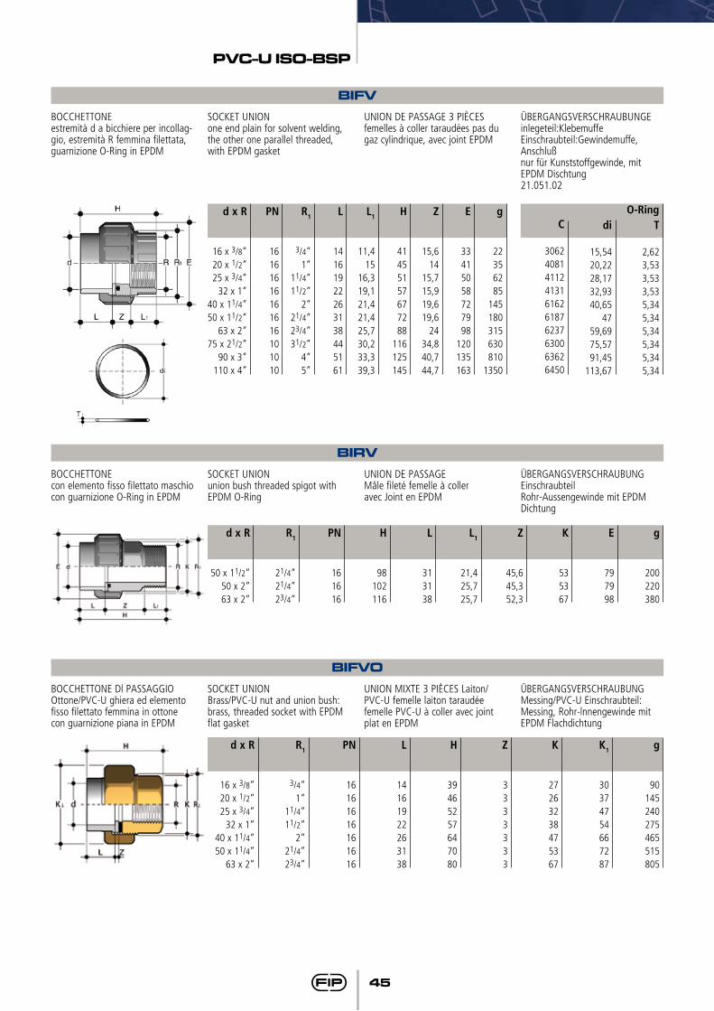
45
PVC-U ISO-BSP
BIFVBOCCHETTONEestremità d a bicchiere per incollag-gio, estremità R femmina filettata, guarnizione O-Ring in EPDM
SOCKET UNIONone end plain for solvent welding, the other one parallel threaded, with EPDM gasket
UNION DE PASSAGE 3 PIÈCESfemelles à coller taraudées pas du gaz cylindrique, avec joint EPDM
ÜBERGANGSVERSCHRAUBUNGEinlegeteil:KlebemuffeEinschraubteil:Gewindemuffe, Anschlußnur für Kunststoffgewinde, mit EPDM Dischtung21.051.02
L
14161922263138445161
R1
3/4”1”
11/4”11/2”
2”21/4”23/4”31/2”
4”5”
g
22356285
145180315630810
1350
d x R
16 x 3/8”20 x 1/2”25 x 3/4”
32 x 1”40 x 11/4”50 x 11/2”
63 x 2”75 x 21/2”
90 x 3”110 x 4”
PN
16161616161616101010
L1
11,415
16,319,121,421,425,730,233,339,3
H
41455157677288
116125145
Z
15,614
15,715,919,619,6
2434,840,744,7
E
33415058727998
120135163
C
3062408141124131616261876237630063626450
T
2,623,533,533,535,345,345,345,345,345,34
di
15,5420,2228,1732,9340,65
4759,6975,5791,45
113,67
O-Ring
BIRVBOCCHETTONEcon elemento fisso filettato maschiocon guarnizione O-Ring in EPDM
SOCKET UNIONunion bush threaded spigot with EPDM O-Ring
UNION DE PASSAGEMâle fileté femelle à colleravec Joint en EPDM
ÜBERGANGSVERSCHRAUBUNGEinschraubteilRohr-Aussengewinde mit EPDM Dichtung
g
200220380
H
98102116
L
313138
L1
21,425,725,7
Z
45,645,352,3
K
535367
E
797998
PN
161616
R1
21/4”21/4”23/4”
d x R
50 x 11/2”50 x 2”63 x 2”
BIFVOBOCCHETTONE Dl PASSAGGIO Ottone/PVC-U ghiera ed elemento fisso filettato femmina in ottonecon guarnizione piana in EPDM
SOCKET UNION Brass/PVC-U nut and union bush: brass, threaded socket with EPDM flat gasket
UNION MIXTE 3 PIÈCES Laiton/PVC-U femelle laiton taraudée femelle PVC-U à coller avec joint plat en EPDM
ÜBERGANGSVERSCHRAUBUNGMessing/PVC-U Einschraubteil: Messing, Rohr-lnnengewinde mit EPDM Flachdichtung
g
90145240275465515805
L
14161922263138
H
39465257647080
Z
3333333
K
27263238475367
K1
30374754667287
PN
16161616161616
R1
3/4”1”
11/4”11/2”
2”21/4”23/4”
d x R
16 x 3/8”20 x 1/2”25 x 3/4”
32 x 1”40 x 11/4”50 x 11/4”
63 x 2”
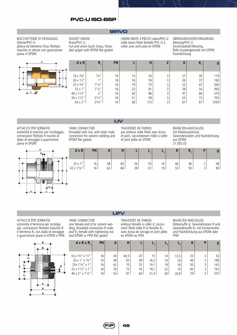
46
PVC-U ISO-BSP
LIVATTACCO PER SERBATOIestremità d maschio per incollaggio, connessioni filettate R munite di dado di serraggio e guarnizione piana in EPDM
TANK CONNECTORthreaded with nut, with plain male connection for solvent welding and EPDM flat gasket
TRAVERSÉE DE PAROISpar embout mâle fileté avec ècrou et joint, raccordement mâle à coller et joint plâte en EPDM
BEHÄLTER-ANSCHLUSSmit Klebestutzen/zyl.Gewindestutzen und Flachdichtung aus EPDM21.092.02
g
5890
L1
1922
L2
1618
H
6066
P
22
K
4655
K1
4650
L
2628
PN
1616
A
5862
d x R
25 x 1”32 x 11/4”
LIFVATTACCO PER SERBATOIestremità d femmina per incollag-gio, connessioni filettate maschio R e femmina R1 con dado di serraggio e guarnizione piana in EPDM o FPM
TANK CONNECTORone female end d for solvent wel-ding, threaded connection R male and R1 female with tightening nut and EPDM or FPM flat gasket
TRAVERSÉE DE PAROISembout femelle à coller d, raccor-ment fileté mâle R et femelle R1 avec écrou de serrage et joint plâte en EPDM ou FPM
BEHÄLTER-ANSCHLUSSKlebemuffe d, Gewindstutzen R und Gewindemuffe R1 mit Kontermutter und Flachdichtung aus EPDM oder FPM
g
53108142192337
A
4458627692
K
3346506079
L
4749525460
L1
1516,319,119,121,4
L2
1416192226
H
60,565707381
P
33333
L3
13,5161819
20,8
PN
1616161616
d x R x R1
16 x 3/4” x 1/2”20 x 1” x 3/4”25x 11/4” x 1”
32 x 11/2” x 1”40 x 2” x 11/2”
BIRVOBOCCHETTONE Dl PASSAGGIO Ottone/PVC-U ghiera ed elemento fisso filettato maschio in ottone con guarnizione piana in EPDM
SOCKET UNION Brass/PVC-U nut and union bush: brass, threa-ded spigot with EPDM flat gasket
UNION MIXTE 3 PIÈCES Laiton/PVC-Umâle laiton fileté femelle PVC-U à coller avec joint plat en EPDM
ÜBERGANGSVERSCHRAUBUNGMessing/PVC-UEinschraubteil:Messing,Rohr-Aussengewinde mit EPDM Flachdichtung
g
110160300360570705
1050
L
14161922263138
H
505975818699
113
Z
3333333
K
27263238475367
K1
30374754667287
PN
16161616161616
R1
3/4”1”
11/4”11/2”
2”21/4”23/4”
d x R
16 x 3/8”20 x 1/2”25 x 3/4”
32 x 1”40 x 11/4”50 x 11/2”
63 x 2”
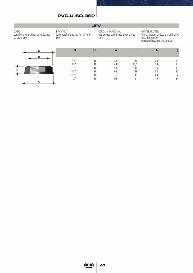
47
PVC-U ISO-BSP
JFVDADOcon filettatura cilindrica (utilizzato su LIV e LIFV)
BACK NUTwith parallel threads for LIV and LIFV
ÉCROU HEXAGONALpas du gaz cylindrique pour LIV et LIFV
KONTERMUTTERfür Behälteranschlüsse LIV und LIFV. Anschluß nur fürKunststoffgewinde 21.092.00
g
111431325284
H
1313,5
16181921
K
283346506079
A
384458627692
PN
161616161616
R
1/2” 3/4”
1”11/4”11/2”
2”
Raccordi serie filettataThreaded fittings seriesRaccords serie filetéGewindefittings
BSP

50
PVC-U BSP
I dati del presente prospetto sono forniti in buona fede. La FIP non si assume alcu-na responsabilità su quei dati non diret-tamente derivati da norme internazionali. La FIP si riserva di apportarvi qualsiasi modifica.
The data given in this leaflet are offered in good faith. No liability can be accepted concerning technical data that are not directly covered by recognized interna-tional standards. FIP reserves the right to carry out any modification to the products shown in this Ieaflet.
Les données contenues dans cette brochure sont fournies en bonne foi. FIP n’assume aucune responsabilité pour les données qui ne dérivent pas directement des normes internationa-les. FIP garde le droit d’apporter toute modification aux produits présentés dans cette brochure.
Alle Daten dieser Druckschrift wurden nach bestem Wissen angegeben, jedoch besteht keine Verbindlichkeit, sofern sie nicht direkt internationalen Normen entnommen wurden. Die Än-derung von Maßen oder Ausführungen bleibt FIP vorbehalten.
51
PVC-U BSP
•Gamma dimensionale da R 3/8” a R 4”
•Resistenza a pressioni di esercizio fino a 16 bar a 20° C (acqua)
•Temperatura massima di esercizio: 60° C
•Materiale: Cloruro di polivinile rigido PVC-U
•Colore: grigio RAL 7011
•Sistema di giunzione mediante filettatura
•Guarnizioni in EPDM o FPM
•Size range: from R 3/8” to R 4”
•Pressure rating: max working pres-sure 16 bar at 20° C (water)
•Maximum working temperature: 60° C
•Material: Unplasticized polyvinyl chloride PVC-U
•Colour: grey RAL 7011
•Jointing technique: threaded con-nection
•Sealing gaskets: EPDM or FPM
•Gamme dimensionnelle de R 3/8” a R 4”
•Résistance aux pressions de servi-ce jusqu’à 16 bar à 20° C (eau)
•Température maximale de service: 60° C
•Matériel: Polychlorure de vinyle non plastifié PVC-U
•Coleur: gris RAL 7011
•Système de jonction avec filetage
•Joints en EPDM ou FPM
•Abmessungen von R 3/8” bis R 4”
•Druckstufe bis PN 16 bar bei 20° C (Wasser)
•Maximale Betriebstemperatur: 60° C
•Material: Polyvinylchlorid, hart ohne Weichmacher PVC-U
•Farbe: grau RAL 7011
•Verbindungstechnik: Gewinde
•Dichtungen aus EPDM - FPM
Raccordi serie filettata
Threaded fittings series
GewindefittingsRaccords serie fileté
Legenda
DN diametro nominale interno in mm
R dimensione nominale della Filettatura in
pollici
PN pressione nominale in bar (pressione max di esercizio a 20° C - acqua)
g Peso in grammi
K chiave
b bulloni
C codice di riferimento o-ring
PVC-U polivinile di cloruro rigido. MRS-25
FPM (FKM) fluoroelastomero
EPDM elastomero etilene pro-pilene
DN nominal internal diameter in mm
R nominal sizes of the thread in inches
PN nominal pressure in bar (max working pressure at 20° C – water)
g weight in grams
K key
b bolts
C o-ring code
PVC-U un-plasticized poly vinyl chloride. MRS-25
FPM (FKM) vinylidene fluoride rubber
EPDM ethylene propylene rubber
DN diamètre intérieur nominal en mm
R dimension nominale du filetage en pouces
PN pression nominale en bar (pression maximale de service 20° C – eau)
g Poids en grammes
K clef
b boulons
C référence O-rin
PVC-U polychlorure de vinyle non plastifié. MRS-25
FPM (FKM) fluoro-élastomère
EPDM élastomère éthylène propylène
DN Innendurchmesser (NW), in mm
R Abmessung des Gewindes in Zoll
PN Nenndruck in bar (maximaler Betriebsdruck bei Wasser 20° C)
g Gewicht in Gramm
K Schlüsselweite
b Schrauben
C O-Ring Code
PVC-U Polyvinylchlorid, hart ohne Weichmacher. MRS-25
FPM (FKM) Fluorelastomer
EPDM Ethylen-Propylen-Dien Elastomer

52
PVC-U BSP
Dimensioni Dimensions Dimensions DimensionenLa FIP ha approntato una gamma di raccordi i cui attacchi sono in accordo con le seguenti norme:accoppiabili con tubi secondo ISO 161/1, UNI-EN 1452, ISO 15493, DIN 8062, NF EN 1452, KIWA BRL-502. Filettatura: UNI ISO 228/1, DIN 2999, BS 21.
FIP have produced a complete range of fittings whose couplings comply with the following stan-dards:coupling to pipes complying withISO 161/1, UNI-EN 1452, ISO 15493, DIN 8062, NF EN 1452, KIWA BRL-502.Threaded couplings: UNI ISO 228/1, DIN 2999, BS 21.
FIP a crée une gamme complè-te de raccords dont les raccords con-formes aux normes suivantes:assemblés à des tubes selon ISO 161/1, UNI-EN 1452, ISO 15493, DIN 8062, NF EN 1452, KIWA BRL-502. Filetage: UNI ISO 228/1, DIN 2999, BS 21.
FIP-Fittings aus PVC-hart ent-sprechen in ihren Anschlüssen folgenden Normen:und können ver-bunden werden mit Rohren nach ISO 1616/1, UNI-EN 1452, ISO 15493, DIN 8062, NF EN 1452, KIWA BRL-502.Gewindefittings: UNI ISO 228/1, DIN 2999, BS 21.
GFV
HFV
GOMITO A 90°estremità femmina filettate
GOMITO A 45°estremità femmina filettate
ELBOW 90°parallel threaded sockets
ELBOW 45°parallel threaded sockets
COUDE 90°taraudées pas du gaz cylindrique
COUDE 45°taraudées pas du gaz cylindrique
WINKEL 90°beidseitig GewindemuffenAnschluß nur fürKunststoffgewinde21.010.06
WINKEL 45°beidseitig GewindemuffenAnschluß nur fürKunststoffgewinde21.015.06
g
16244072
130185350450835
1135
g
18244568
154255345625
Z
13131721273646556680
Z
6,58
10,51521263139
E
23,528,5
354354617691
108130
E
28334150647690
107
L
11,415
16,319,121,421,425,730,233,339,3
L
1516,319,121,421,425,730,233,3
PN
16161616161616161616
PN
1616161616161616
R
3/8”1/2”3/4”
1”11/4”11/2”
2”21/2”
3”4”
R
1/2”3/4”
1”11/4”11/2”
2”21/2”
3”
RRRRRRRRRR
RRRRRRRR
R: RINA
R: RINA
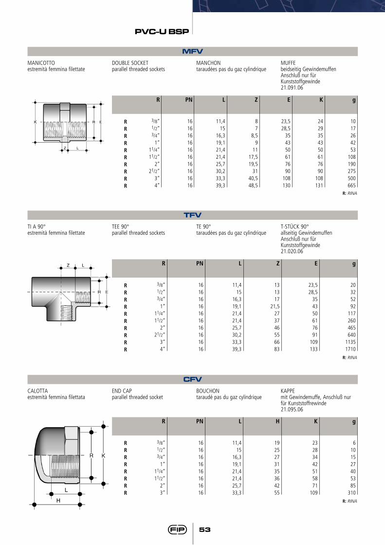
53
PVC-U BSP
MFVMANICOTTOestremità femmina filettate
DOUBLE SOCKETparallel threaded sockets
MANCHONtaraudées pas du gaz cylindrique
MUFFEbeidseitig GewindemuffenAnschluß nur fürKunststoffgewinde21.091.06
g
1017264253
108190275500665
Z
87
8,59
1117,519,5
3140,548,5
E
23,528,5
354350617690
108130
K
2429354350617690
108131
L
11,415
16,319,121,421,425,730,233,339,3
PN
16161616161616161616
R
3/8”1/2”3/4”
1”11/4”11/2”
2”21/2”
3”4”
RRRRRRRRRR
R: RINA
TFVTI A 90°estremità femmina filettate
TEE 90°parallel threaded sockets
TE 90°taraudées pas du gaz cylindrique
T-STÜCK 90°allseitig GewindemuffenAnschluß nur fürKunststoffgewinde21.020.06
g
20325292
117260465640
11351710
Z
131317
21,5273746556683
E
23,528,5
354350617691
109133
L
11,415
16,319,121,421,425,730,233,339,3
PN
16161616161616161616
R
3/8”1/2”3/4”
1”11/4”11/2”
2”21/2”
3”4”
RRRRRRRRRR
R: RINA
CFVCALOTTAestremità femmina filettata
END CAPparallel threaded socket
BOUCHONtaraudé pas du gaz cylindrique
KAPPEmit Gewindemuffe, Anschluß nur für Kunststoffrewinde21.095.06
g
6101527405385
310
H
1925273135364255
K
23283442515871
109
L
11,415
16,319,121,421,425,733,3
PN
1616161616161616
R
3/8”1/2”3/4”
1”11/4”
11/2” 2”3”
RRRRRRRR
R: RINA

54
PVC-U BSP
NFVNIPPLOestremità maschio filettate
BARREL NIPPLEboth ends parallel threaded
MAMELON DOUBLEfiletés pas du gaz cylindrique
DOPPELNIPPELbeidseitig zyl. Gewindestutzen,Anschluß nur fürKunststoffgewinde21.091.19
g
5101627405593
150225380
K
182328354451648095
120
E
22283440525870
---
L
11,415
16,319,121,421,425,730,233,3
39
Fig
AAAAAAABBB
H
33414551575868788597
PN
16161616161616161616
R
3/8”1/2”3/4”
1”11/4”11/2”
2”**21/2”
**3”**4”
RRRRRRR
R: RINA
**fattore di sicurezza ridotto **reduced safety factor **facteur de securité réduit **mit reduziertem Sicherheits- faktor
Fig. A
Fig. B
PFVTAPPOestremità maschio filettata
MALE PLUGparallel threaded end
BOUCHON MÂLEfileté pas du gaz cylindrique
STOPFENmit zyl. GewindestutzenAnschluß nur fürKunststoffgewinde21.096.09
g
48
1121304674
180245550
H
22263034384047617187
E
22283440525870
---
K
182328354451648093
118
Fig
AAAAAAABBB
L
11,415
16,319,121,421,425,730,233,339,3
PN
16161616161616161616
R
3/8”1/2”3/4”
1”11/4”
11/2”2”
21/2”3”4”
RRRRRRRRRR
R: RINA
Fig. A
Fig. B
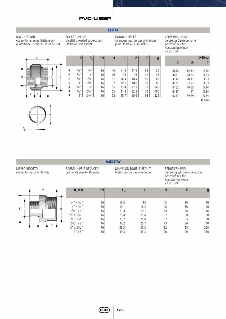
55
PVC-U BSP
RRRRRRR
BFVBOCCHETTONEestremità femmina filettate con guarnizione O-ring in EPDM o FPM
SOCKET-UNIONparallel threaded sockets with EPDM or FPM gasket
UNION 3 PIÈCEStaraudées pas du gaz cylindrique joint EPDM ou FPM inclus
VERSCHRAUBUNGbeidseitig GewindemuffenAnschluß nur fürKunststoflgewinde21.051.06
PN
16161616161616
R1
3/4”1”
11/4”11/2”
2”21/4”23/4”
g
22356585
145180325
R
3/8”1/2”3/4”
1”11/4”11/2”
2”
H
40465157656578
L
11,415
16,319,121,421,425,7
Z
17,216
18,418,822,222,226,6
E
33415058727998
C
3062408141124131616261876237
T
2,623,533,533,535,345,345,34
di
15,5420,2228,1732,9340,65
4759,69
O-Ring
R: RINA
NRFVNIPPLO RIDOTTOestremità maschio filettate
BARREL NIPPLE REDUCEDboth ends parallel threaded
MAMELON DOUBLE RÉDUITfiletés pas du gaz cylindrique
REDUZIERNIPPELbeidseitig zyl. GewindestutzenAnschluß nur fürKunststoffgewinde21.091.29
g
1626466088
140220350
L
1516,319,121,421,425,730,233,3
H
4348545762738290
K
30364650658095
120
L1
16,319,121,421,425,730,233,339,3
PN
1616161616161616
R1 x R
3/4” x 1/2”1” x 3/4”
11/4” x 1”11/2” x 11/4”
2” x 11/2”21/2” x 2”3” x 21/2”
4” x 3”
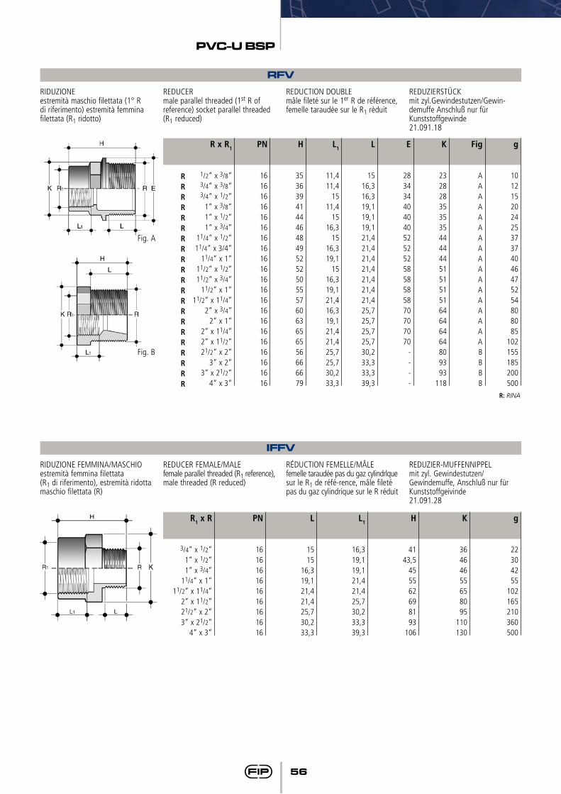
56
PVC-U BSP
RFVRIDUZIONEestremità maschio filettata (1° R di riferimento) estremità femmina filettata (R1 ridotto)
REDUCERmale parallel threaded (1st R of reference) socket parallel threaded (R1 reduced)
REDUCTION DOUBLEmâle fileté sur le 1er R de référence, femelle taraudée sur le R1 rèduit
REDUZIERSTÜCKmit zyl.Gewindestutzen/Gewin-demuffe Anschluß nur für Kunststoffgewinde21.091.18
g
10121520242537374046475254808085
102155185200500
L1
11,411,4
1511,4
1516,3
1516,319,1
1516,319,121,416,319,121,421,425,725,730,233,3
L
1516,316,319,119,119,121,421,421,421,421,421,421,425,725,725,725,730,233,333,339,3
E
2834344040405252525858585870707070
----
K
2328283535354444445151515164646464809393
118
Fig
AAAAAAAAAAAAAAAAABBBB
H
353639414446484952525055576063656556666679
PN
161616161616161616161616161616161616161616
R x R1
1/2” x 3/8”3/4” x 3/8”3/4” x 1/2”
1” x 3/8”1” x 1/2”1” x 3/4”
11/4” x 1/2”11/4” x 3/4”
11/4” x 1”11/2” x 1/2”11/2” x 3/4”
11/2” x 1”11/2” x 11/4”
2” x 3/4”2” x 1”
2” x 11/4”2” x 11/2”21/2” x 2”
3” x 2”3” x 21/2”
4” x 3”
RRRRRRRRRRRRRRRRRRRRR
R: RINA
Fig. A
Fig. B
IFFVRIDUZIONE FEMMINA/MASCHIOestremità femmina filettata(R1 di riferimento), estremità ridotta maschio filettata (R)
REDUCER FEMALE/MALEfemale parallel threaded (R1 reference), male threaded (R reduced)
RÉDUCTION FEMELLE/MÂLEfemelle taraudée pas du gaz cyIindrlque sur le R1 de réfé-rence, mâle fileté pas du gaz cylindrique sur le R réduit
REDUZIER-MUFFENNIPPEL mit zyl. Gewindestutzen/ Gewindemuffe, Anschluß nur für Kunststoffgeivinde 21.091.28
g
22304255
102165210360500
L1
16,319,119,121,421,425,730,233,339,3
H
4143,5
455562698193
106
K
36464655658095
110130
L
1515
16,319,121,421,425,730,233,3
PN
161616161616161616
R1 x R
3/4” x 1/2” 1” x 1/2” 1” x 3/4”
11/4” x 1” 11/2” x 11/4”
2” x 11/2” 21/2” x 2” 3” x 21/2”
4” x 3”
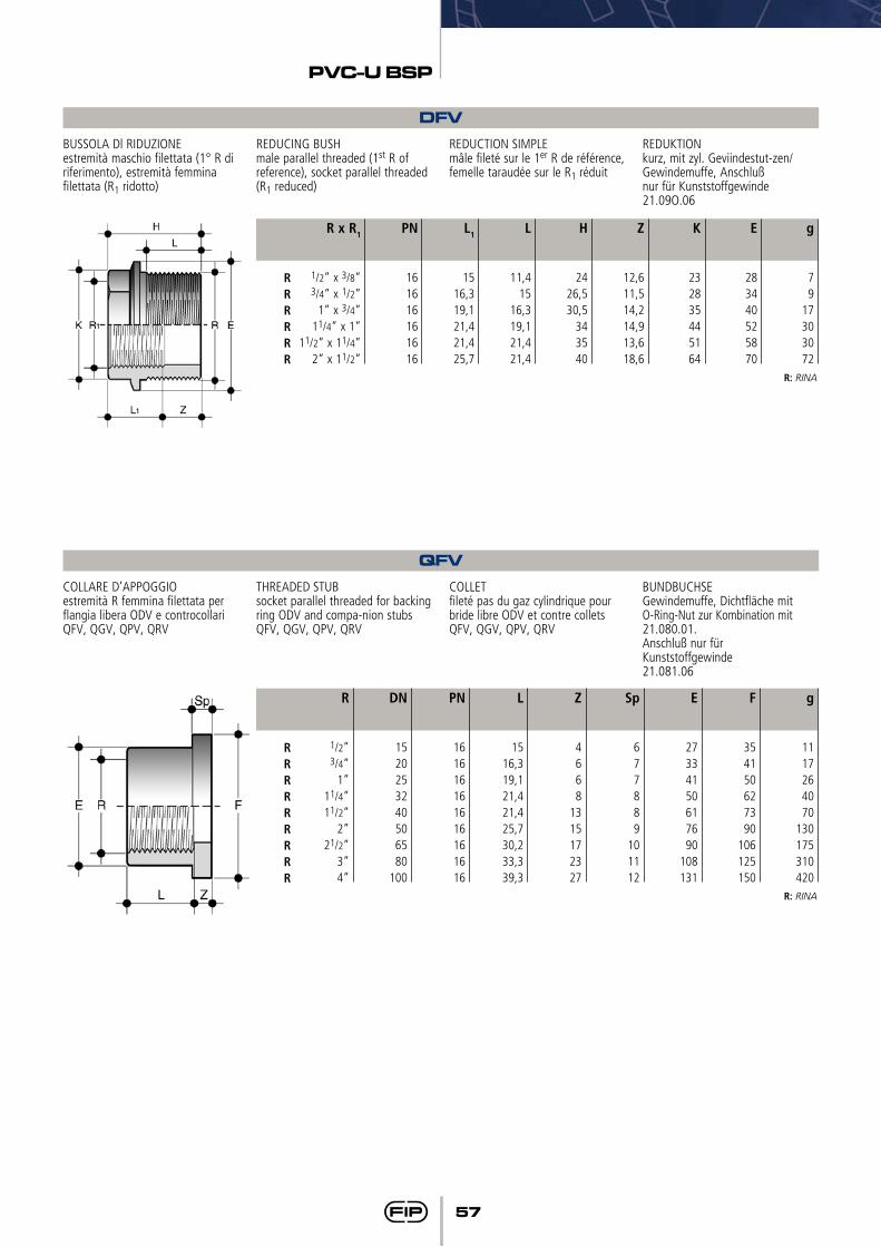
57
PVC-U BSP
DFVBUSSOLA Dl RIDUZIONEestremità maschio filettata (1° R di riferimento), estremità femmina filettata (R1 ridotto)
REDUCING BUSHmale parallel threaded (1st R of reference), socket parallel threaded (R1 reduced)
REDUCTION SIMPLEmâle fileté sur le 1er R de référence, femelle taraudée sur le R1 réduit
REDUKTIONkurz, mit zyl. Geviindestut-zen/Gewindemuffe, Anschlußnur für Kunststoffgewinde21.09O.06
g
79
17303072
L
11,415
16,319,121,421,4
H
2426,530,5
343540
Z
12,611,514,214,913,618,6
K
232835445164
E
283440525870
L1
1516,319,121,421,425,7
PN
161616161616
R x R1
1/2” x 3/8”3/4” x 1/2”
1” x 3/4”11/4” x 1”
11/2” x 11/4”2” x 11/2”
RRRRRR
R: RINA
QFVCOLLARE D’APPOGGIOestremità R femmina filettata per flangia libera ODV e controcollari QFV, QGV, QPV, QRV
THREADED STUBsocket parallel threaded for backing ring ODV and compa-nion stubs QFV, QGV, QPV, QRV
COLLETfileté pas du gaz cylindrique pour bride libre ODV et contre collets QFV, QGV, QPV, QRV
BUNDBUCHSEGewindemuffe, Dichtfläche mitO-Ring-Nut zur Kombination mit21.080.01.Anschluß nur fürKunststoffgewinde21.081.06
g
1117264070
130175310420
L
1516,319,121,421,425,730,233,339,3
Z
4668
1315172327
Sp
677889
101112
E
27334150617690
108131
F
354150627390
106125150
PN
161616161616161616
DN
1520253240506580
100
R
1/2”3/4”
1”11/4” 11/2”
2”21/2”
3”4”
RRRRRRRRR
R: RINA
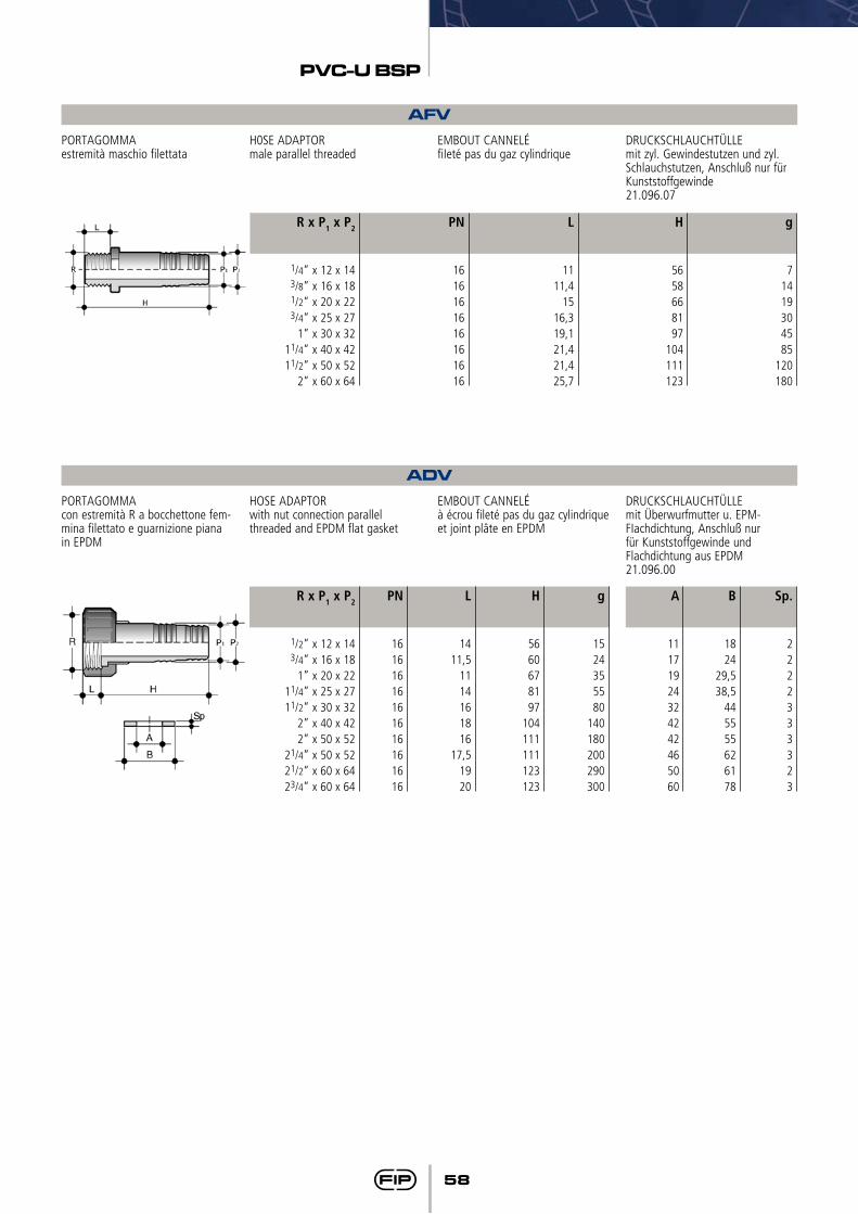
58
PVC-U BSP
AFV
ADV
PORTAGOMMAestremità maschio filettata
PORTAGOMMAcon estremità R a bocchettone fem-mina filettato e guarnizione piana in EPDM
H0SE ADAPTORmale parallel threaded
HOSE ADAPTORwith nut connection parallelthreaded and EPDM flat gasket
EMBOUT CANNELÉfiIeté pas du gaz cylindrique
EMBOUT CANNELÉà écrou fileté pas du gaz cylindrique et joint plâte en EPDM
DRUCKSCHLAUCHTÜLLEmit zyl. Gewindestutzen und zyl. Schlauchstutzen, Anschluß nur für Kunststoffgewinde21.096.07
DRUCKSCHLAUCHTÜLLEmit Überwurfmutter u. EPM-FIachdichtung, Anschluß nur für Kunststoffgewinde und Flachdichtung aus EPDM21.096.00
g
71419304585
120180
Sp.
2222333323
H
5658668197
104111123
A
11171924324242465060
B
1824
29,538,5
445555626178
L
1111,4
1516,319,121,421,425,7
g
1524355580
140180200290300
PN
1616161616161616
PN
16161616161616161616
L
1411,5
1114161816
17,51920
H
5660678197
104111111123123
R x P1 x P2
1/4” x 12 x 14 3/8” x 16 x 181/2” x 20 x 22 3/4” x 25 x 27
1” x 30 x 3211/4” x 40 x 42 11/2” x 50 x 52
2” x 60 x 64
R x P1 x P2
1/2” x 12 x 14 3/4” x 16 x 18
1” x 20 x 22 11/4” x 25 x 27 11/2” x 30 x 32
2” x 40 x 42 2” x 50 x 52
21/4” x 50 x 5221/2” x 60 x 64 23/4” x 60 x 64
Raccordi per incollaggio e filettatiSolvent welding and threaded fittingsRaccords à coller et filetéKlebe und Gewindefittings
BS
62
PVC-U BS
I dati del presente prospetto sono forniti in buona fede. La FIP non si assume alcu-na responsabilità su quei dati non diret-tamente derivati da norme internazionali. La FIP si riserva di apportarvi qualsiasi modifica.
The data given in this leaflet are offered in good faith. No liability can be accepted concerning technical data that are not directly covered by recognized interna-tional standards. FIP reserves the right to carry out any modification to the products shown in this Ieaflet.
Les données contenues dans cette brochure sont fournies en bonne foi. FIP n’assume aucune responsabilité pour les données qui ne dérivent pas directement des normes internationa-les. FIP garde le droit d’apporter toute modification aux produits présentés dans cette brochure.
Alle Daten dieser Druckschrift wurden nach bestem Wissen angegeben, jedoch besteht keine Verbindlichkeit, sofern sie nicht direkt internationalen Normen entnommen wurden. Die Än-derung von Maßen oder Ausführungen bleibt FIP vorbehalten.
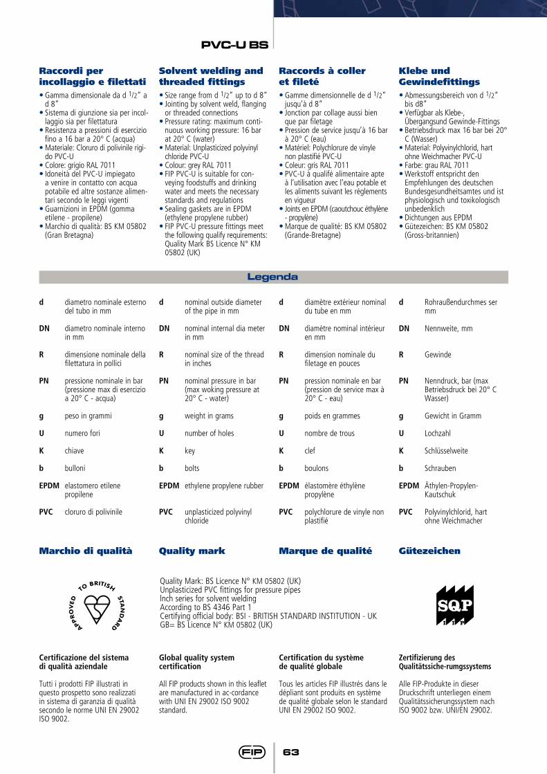
63
PVC-U BS
Raccordi per incollaggio e filettati
Marchio di qualità
Solvent welding and threaded fittings
Quality mark
Raccords à coller et fileté
Marque de qualité
Klebe und Gewindefittings
Gütezeichen
• Gamma dimensionale da d 1/2” a d 8”
• Sistema di giunzione sia per incol-laggio sia per filettatura
• Resistenza a pressioni di esercizio fino a 16 bar a 20° C (acqua)
•Materiale: Cloruro di polivinile rigi-do PVC-U
•Colore: grigio RAL 7011• Idoneità del PVC-U impiegato
a venire in contatto con acqua potabile ed altre sostanze alimen-tari secondo le leggi vigenti
• Guarnizioni in EPDM (gomma etilene - propilene)
• Marchio di qualità: BS KM 05802 (Gran Bretagna)
Certificazione del sistema di qualità aziendale
Tutti i prodotti FIP illustrati in questo prospetto sono realizzati in sistema di garanzia di qualità secondo le norme UNI EN 29002 ISO 9002.
• Size range from d 1/2” up to d 8”• Jointing by solvent weld, flanging
or threaded connections• Pressure rating: maximum conti-
nuous working pressure: 16 bar at 20° C (water)
•Material: Unplasticized polyvinyl chloride PVC-U
•Colour: grey RAL 7011• FIP PVC-U is suitable for con-
veying foodstuffs and drinking water and meets the necessary standards and regulations
• Sealing gaskets are in EPDM (ethylene propylene rubber)
• FIP PVC-U pressure fittings meet the following qualify requirements: Quality Mark BS Licence N° KM 05802 (UK)
Global quality system certification
All FIP products shown in this leaflet are manufactured in ac-cordance with UNI EN 29002 ISO 9002 standard.
• Gamme dimensionnelle de d 1/2” jusqu’à d 8”
• Jonction par collage aussi bien que par filetage
• Pression de service jusqu’à 16 bar à 20° C (eau)
•Matériel: Polychlorure de vinyle non plastifié PVC-U
•Coleur: gris RAL 7011• PVC-U à qualifé alimentaire apte
à l’utilisation avec l’eau potable et les aliments suivant les réglements en vigueur
• Joints en EPDM (caoutchouc éthylène - propylène)
• Marque de qualité: BS KM 05802 (Grande-Bretagne)
Certification du système de qualité globale
Tous les articles FIP illustrés dans le dépliant sont produits en système de qualité globale selon le standard UNI EN 29002 ISO 9002.
• Abmessungsbereich von d 1/2” bis d8”
• Verfügbar als Klebe-, Übergangsund Gewinde-Fittings
• Betriebsdruck max 16 bar bei 20° C (Wasser)
•Material: Polyvinylchlorid, hart ohne Weichmacher PVC-U
•Farbe: grau RAL 7011• Werkstoff entspricht den
Empfehlungen des deutschen Bundesgesundheitsamtes und ist physiologisch und toxikologisch unbedenklich
• Dichtungen aus EPDM• Gütezeichen: BS KM 05802
(Gross-britannien)
Zertifizierung des Qualitätssiche-rumgssystems
Alle FIP-Produkte in dieserDruckschrift unterliegen einemQualitätssicherungssystem nachISO 9002 bzw. UNI/EN 29002.
Legenda
d diametro nominale esterno del tubo in mm
DN diametro nominale interno in mm
R dimensione nominale della filettatura in pollici
PN pressione nominale in bar (pressione max di esercizio
a 20° C - acqua)
g peso in grammi
U numero fori
K chiave
b bulloni
EPDM elastomero etilene propilene
PVC cloruro di polivinile
d nominal outside diameter of the pipe in mm
DN nominal internal dia meter in mm
R nominal size of the thread in inches
PN nominal pressure in bar (max woking pressure at
20° C - water)
g weight in grams
U number of holes
K key
b bolts
EPDM ethylene propylene rubber
PVC unplasticized polyvinyl chloride
d diamètre extérieur nominal du tube en mm
DN diamètre nominal intérieur en mm
R dimension nominale du filetage en pouces
PN pression nominale en bar (pression de service max à 20° C - eau)
g poids en grammes
U nombre de trous
K clef
b boulons
EPDM élastomère éthylène propylène
PVC polychlorure de vinyle non plastifié
d Rohraußendurchmes ser mm
DN Nennweite, mm
R Gewinde
PN Nenndruck, bar (max Betriebsdruck bei 20° C Wasser)
g Gewicht in Gramm
U Lochzahl
K Schlüsselweite
b Schrauben
EPDM Äthylen-Propylen- Kautschuk
PVC Polyvinylchlorid, hart ohne Weichmacher
Quality Mark: BS Licence N° KM 05802 (UK)Unplasticized PVC fittings for pressure pipeslnch series for solvent weldingAccording to BS 4346 Part 1Certifying official body: BSI - BRITISH STANDARD INSTITUTION - UKGB= BS Licence N° KM 05802 (UK)APP
RO
VED
TOBRITISH
STAN
DARD

64
PVC-U BS
Dati Tecnici Technical Data Données Techniques Technische Daten
1
3
1
2
210 -1 h bar
1 1 0 1 0 2 10 3 10 5
60 50
1516
12 9
6
A 0
B 0
C 0
A 2
B 2
C 2
1 2 5 5 0
0 D D2
10 10 4
anni - years - années - Jahre
bar
16
14
12
10
8
6
4
2
0
20 40 ° C 60 100 0 80
CLASS E
CLASS D
CLASS C
pres
sione
di e
serc
izio
- wor
king
pre
ssur
epr
essio
n de
ser
vice
- Bet
riebs
druc
k
temperatura di esercizio - working temperaturetempérature de service - Betriebstemperatur
Variazione della pressione in funzione della temperatura per acqua o fluidi non pericolosi nei confronti dei quali il PVC é classifi-cato CHIMICAMENTE RESISTENTE. Vedere il prospetto “Guida alla resistenza chimica”. In altri casi è richiesta un’adeguata diminuzione della pressione nominale PN.
Pressure temperature rating for water and harmless fluids to which PVC is RESISTANT. See “A guide to chemicai resistance”. In other cases a reduction of the rated PN is required.
Variation de la pression en fonction de la température pour l’eau et les fluides non agressifs pour lequel le PVC est considéré CHIMIQUEMENT RESISTANT. Voir brochure “Guide de résistance chimique”. Pour Ies autres cas une diminution du PN est nécessaire.
Druck/Temperatur-Diagramm für Wasser und ungefährliche Medien gegen die PVC bestän-dig ist. Siehe Beständigkeitsli-ste. In allen anderen Fällen ist eine entsprechende Reduzie-rung der Druckstufe erforder-lich.
Diagramma della pressione di scop-pio nel lungo termine peri raccordi FIP da incollare e dipassaggio
: Raccordi FIP classe E
: Curva della pressione di scoppio nel lungo termine dei
raccordi in PVC da incollare e di passag-gio classe E secon-do le norme BS 4346
: Pressione d’esercizio a 20° C
classe E: 15 bar (B0 ÷ B2) classe D: 12 bar (C0 ÷ C2) classe C: 9 bar (D0 ÷ D2)
Long-term burst pressure curve of FIP solvent welding and adaptor fittings
: PVC-U fittings class E
: Long term burst pressure curve of PVC solvent welding
and adaptor fitting class E according to BS 4346 : Working pressure at 20° C
class E: 15 bar (B0 ÷ B2) class D: 12 bar (C0 ÷ C2) class C: 9 bar (D0 ÷ D2)
Diagramme a longue durée de pression maximale des rac-cords FIP à coller et d’adap-tation
: Raccords en PVC FIP classe E : Pression forcée des raccords
FIP à coller et d’adaptation classe E selon BS 4346
: Pression de service à 20° C classe E: 15 bar (B0 ÷ B2) classe D: 12 bar (C0 ÷ C2) classe C: 9 bar (D0 ÷ D2)
Druck-Zeit-Diagramm für FIP-Klebe- und Übergangsfittings bei unge-fährlichen Medien
: FIP Fittings Klasse E
: Mindestzeitstandwerte für Klebe-und Übergangsfittings Klasse E (entsprechend DIN 8063, BS 4346)
: Betriebsdruck bei 20° C
Klasse E: 15 bar (B0 ÷ B2) Klasse D: 12 bar (C0 ÷ C2) Klasse O: 9 bar (D0 ÷ D2)
1h
3,60
4,50
6
15 bar
12 bar
9 bar
PeT 50
anni, yearsannées, Jahre
2,10
2,60
3,50
65
PVC-U BS
3FATTORI DI SICUREZZA A1/B1 oA1/C1 a 20° C pressione di eserci-zio Pe/tempo di utilizzo T
CLASSI DI PRESSIONEI raccordi BS sono suddivisi in classi di pressione in funzione delle quali essi vengono calcolati e scelti per l’impiego. La massima pressione d’esercizio continua a 20° C nel trasporto d’acqua deve essere uguale alla classe di pressione in modo da assicurare una corrispon-denza con i fattori di sicurezza. Se non altrimenti specificato le pres-sioni nominali sono le seguenti:• raccordidaincollareda d 1/2” a d 4” classe E da d 6” a d 8” classe D • raccordidipassaggio da d 1/2” a d 2” classe E da d
21/2” a d 4” classe D
SAFETY FACTORS A1/B1 or A1/C1 at 20° C working pressure Pe/loading time T
PRESSURE CLASSESBS fittings are rated in conven-tional pressure classes providing they are used in the correct applications. Maximum allowed working pressure, for non-stop use, at 20° C in conveying water must be equal to class pressure value in order to ensure correspondence to safety factors.lf not otherwise stated nominal pressure of FIP fittings is as follows:• solventweldingfittings from d 1/2”up to d 4”class E
from d 6” upto d 8” class D • adaptorfittings from d 1/2” up to d 2” class E from d 21/2” up to d 4” class D
FACTEURS DE SECURITÉ A1/B1 ou A1/C1 à 20° C pression de service Pe/periode de charge T
LES CLASSES DE PRESSIONLes raccords BS sont considérés d’après de classes conventionelles de pression suivant lequelles ils sont évalués et choisis pour l’emploi.La pression maximale de service permise en cas d’usage continu, à 20° C pour le transport d’eau doit être égale à la valeur de la classe de pression au but d’atteindre une corre-spondance aux facteurs de sûreté.A défaut de specitication, la pres-sion nominale des raccords FIP est la suivante:• raccordsàcoller de d 1/2” jusqu’à d 4” classe E de d 6” jusqu’à d 8” classe D • raccordsd’adaptation de d 1/3” jusqu’à d 2” classe E de d 21/2” jusqu’à d 4” classe D
SICHERHEITSFAKTOR A1/B1oder A1/C1 bei 20° CBetriebsdruck Pe/Zeit T
DRUCKSTUFENBS-Fittings sind in herkömmli-che Druckstufen eingeteilt, eine Voraussetzung für den Gebrauch bei korrekten Anwendungen. Der maximal zulässige Betriebsdruck für Dauerbetrieb bei 20° C, bezo-gen auf Wasser, darf den Wert der jeweiligen Druckstufe nicht übersteigen, womit sichergestellt ist, daß die jeweiligen Sicherheits-faktoren erhalten bleiben. Sofern nicht ausdrücklich anders ver-merkt, haben FIP-Fittings folgende Drucksfufen:• Klebefittings von d 1/2 bis d 4 Class E von d
6 bis d 8 Class D• Übergangsfittings von d 1/2 bis d 2 Class E von d
21/2 bis d4 Class D
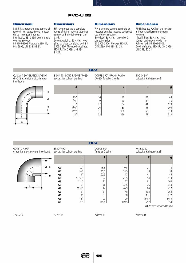
66
PVC-U BS
Dimensioni Dimensions Dimensions DimensionenLa FIP ha approntato una gamma di raccordi i cui attacchi sono in accor-do con le seguenti norme:Incollaggio: BS 4346/1 accop-piabile con tubi secondoBS 3505-3506 Filettatura: ISO R7, DIN 2999, UNI 338, BS 21.
FIP have produced a complete range of fittings whose couplings comply with the following stan-dards:Solvent welding: BS 4346/1 cou-pling to pipes complying with BS 3505-3506. Threaded couplings:ISO R7, DIN 2999, UNI 338, BS 21.
FIP a crée une gamme compléte de raccords dont les raccords conformes aux normes suivantes:Encollage: BS 4346/1 assemblé à des tubes selonBS 3505-3506. Filetage: ISO R7, DIN 2999, UNI 338, BS 21.
FIP-Fittings aus PVC-hart ent-sprechen in ihren Anschlüssen folgenden Normen:Klebefittings: BS 4346/1 und können verbunden werden mit Rohren nach BS 3505-3506. Gewindefittings: ISO 87, DIN 2999, UNI 338, BS 21.
SLVCURVA A 90° GRANDE RAGGIO (R=2D) estremità a bicchiere per incollaggio
BEND 90° LONG RADIUS (R=2D) sockets for solvent welding
COURBE 90° GRAND RAYON (R=2D) femelles à coller
BOGEN 90°beidseitig Klebeanschluß
g
4575
120205310510
E
283441516577
Z
40506480
100126
L
161922263138
d
1/2”3/4”
1”11/4” 11/2”
2”
GLVGOMITO A 90°estremità a bicchiere per incollaggio
ELBOW 90°sockets for solvent welding
COUDE 90°femelles à coller
WINKEL 90°beidseitig Klebeanschtuß
g
153045
110160340427768972
34808850
E
27334154617690
108131
194,5257
Z
10,513,5
1721,5
2733,540,5
485890
169,5
L
16,519,522,5
27313844516390
115,5
d
1/2”3/4”
1”*11/4 ”
11/2” 2”
*21/2”3”4”
*6”*8”
GBGBGBGBGBGBGBGBGBGBGB
GB: BS LICENCE N° 5802 (UK)
*classe D *class D *classe D *Klasse D

67
PVC-U BS
HLVGOMITO A 45°estremità a bicchiere per incollaggio
ELBOW 45°sockets for solvent welding
COUDE 45°femelles à coller
WINKEL 45°beidseitig Klebeanschluß
g
13204585
155291315565740
E
27334150617690
107,5131
Z
55,5
710,511,5
1417
21,526
L
16,519,522,5
263138445161
d
1/2”3/4”
1”*11/4”11/2”
2”*21/2”
3”4”
GBGBGBGBGBGBGBGBGB
*classe D *class D *classe D *Klasse D
GB: BS LICENCE N° 5802 (UK)
MLVMANICOTTOestremità a bicchiere per incollaggio
DOUBLE SOCKETsockets for solvent welding
MANCHONfemelles à coller
MUFFEbeidseitig Klebeanschluß
g
13153658
118206250420680
18004950
E
27334150617690
108131
194,5257
Z
2223334
5,55
1012
L
16,519,522,5
26313844
50,56390
115,5
d
1/2”3/4”
1”*11/4”11/2”
2”*21/2”
3”4”6”
*8”
GBGBGBGBGBGBGBGBGBGBGB
GB: BS LICENCE N° 5802 (UK)
MILVMANICOTTO MM/INCHestremità piane, una a bicchiere per incollaggio su tubi metrici, l’altra a bicchiere per incollaggio su tubi in pollici
DOUBLE SOCKET MM/INCHboth ends plain, one for solvent welding to metric pipe, the other one for solvent welding to inch pipe
MANCHON DE PASSAGEà coller, métrique/pouce BS
ÜBERGANGSMUFFEeinerseits Klebemuffe mm anderer-seits Klebemuffe inch
g
12224465
125210250438852
L1
16,519,522,5
27303644
50,563
E
27334150617690
108131
Z
2.52.52.52.04.05.04.05.54.0
L
161922263138445161
d x d1
20 x 1/2”25 x 3/4”
32 x 1”40 x 11/4”50 x 11/2”
63 x 2”75 x 21/2”
90 x 3”110 x 4”
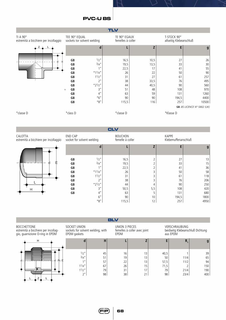
68
PVC-U BS
BLVBOCCHETTONEestremità a bicchiere per incollag-gio, guarnizione O-ring in EPDM
SOCKET UNIONsockets for solvent welding, with EPDM gaskets
UNION 3 PIECESfemelles à coller avec jointEPDM
VERSCHRAUBUNGbeidseitg Klebeanschluß Dichtung aus EPDM
g
396594
150190400
R1
111/411/2
221/423/4
L
161922263138
Z
131313151721
E
40,550
57,571,5
7998
H
455157677998
d
1/2”3/4”
1”11/4” 11/2”
2”
CLVCALOTTAestremità a bicchiere per incollaggio
END CAPsocket for solvent welding
BOUCHONfemelle à coller
KAPPEKlebemuffenanschluß
g
13153658
118206250420680
18004950
E
27334150617690
108131
194,5257
Z
2223334
5,55
1012
L
16,519,522,5
26313844
50,56390
115,5
d
1/2”3/4”
1”*11/4”11/2”
2”*21/2”
3”4”6”
*8”
GBGBGBGBGBGBGBGBGB
TLVTI A 90°estremità a bicchiere per incollaggio
TEE 90° EQUALsockets tor solvent welding
TE 90° EGAUXfemelles à coller
T-STÜCK 90°allseitig Klebeanschluß
g
26305590
257495560970
12604400
10500
E
27334150617690
108131
194,5257
Z
10,513,5
172227
33,540,5
485990
116
L
16,519,522,5
26313844516390
115,5
d
1/2”3/4”
1”*11/4”11/2”
2”*21/2”
3”4”
*6”*8”
GBGBGBGBGBGBGBGBGBGBGB
GB: BS LICENCE N° 5802 (UK)
*classe D *class D *classe D *Klasse D

69
PVC-U BS
DLVBUSSOLA Dl RIDUZIONEestremità maschio per incollaggio (1° d di riferimento) estremità a bic-chiere per incollaggio (d1 ridotto)
REDUCING BUSHspigot for solvent welding (1st d of reference) socket for solvent wel-ding (reduced d1)
REDUCTION SIMPLEmale à coller sur le 1er d de re-ference, femelle à coller sur le d1 reduit
REDUKTIONkurz, mit Klebestutzen und Klebemuffe
g
35,5181019404220755050
100200167125370331972
1400
Fig
AAAAABAABBBABBABABB
Z
23
6,534
107,5
416,5
77
7,520,5
137
271227
25,5
L
16,519,522,522,5
27303031363638
43,550,5
5150,5
636390
115,5
d x d1
1/2” x 3/8”3/4” x 1/2”
1” x 1/2”1” x 3/4”
11/4” x 1”11/2” x 3/4”
11/2” x 1”11/2” x 11/4”
2” x 3/4”2” x 1”
2” x 11/2”21/2” x 2”3” x 11/2”
3” x 2”3” x 21/2”
4” x 2”4” x 3”
*6” x 4”*8” x 6”
GB
GBGB
GB
GB
GB
GBGBGB
GB: BS LICENCE N° 5802 (UK)
*classe D *class D *classe D *Klasse D
Fig. A
Fig. B
QLVCOLLARE D’APPOGGIO PIANO estremità a bicchiere per incol-lag-gio superfici di appoggio piane per controcollari QGV (per le dimensioni delle guarnizioni vedi QHV)
FLAT STUBsockets for solvent welding flat faces for companion stubs QGV (for gasket dimensions see QHV)
COLLETfemelles à coller, siège plat, pour contre collets QGV (voir QHV pour les dimensions des garnitures)
BUNDBUCHSEKlebeanschluß, Dichfläche flach, 21.080.01 zurKombination mit 21.081.01
E
7690
108131188250
F
90106125 150212270
g
110165270445
12502150
Sp
91011121620
Z
33555
8,5
L
3844516186
115
d
2”21/2”
3”4”6”8”

70
PVC-U BS
FLVFLANGIABS 10, tabella E, a bicchiere per incollaggio (per le dimensioni delle guarnizioni vedi QHV)
FLANGEBS 10 table E, sockets for solvent welding (for gasket dimensions see QHV)
FIXEBS 10 table E, femelles à coller série gaz pour joint plats (voir QHV pour les dimensions des garnitures)
FLANSCHBS 10 table E Klebemuffe (Siehe QHV für die Dichtung-sabmessungen)
U
444444448
g
100140200265350500670860
1100
L
16,519,522,5
273138
43,55163
Z
5555555
5,55,5
f
141414141418181818
Sp
11121415161819
20,522,5
a
6773
82,587,598,5
11127146178
E
95105115125140165180200220
d
1/2”3/4”
1”11/4”11/2”
2”21/2”
3”4”
QHV/X - QHV/YGUARNIZIONE PIANA IN EPDM E FPM per collari e flange
FLAT GASKET IN EPDM AND FPM for stubs and backing rings
JOINT PLAT EPDM ET FPMpour collets et brides
FLACHDICHTUNG IN EPDM UND FPM für Bundbuchsen u. Flansche
F
-1414141818181818181818222222222222
U
-44444448888888
121212
B
2732
38,544597188
104123148166186211252270305
--
Sp
2222222223333444--
A1
-1722283645577184
102118132152192215238265290
B1
-95
107117
142,5153,3
168187,5
203223230250
288,5340340395395462
Sp
-22222233333444444
I
-65
76,386,5101111
125,5145,5
160181190210
241,5295295350350400
A
162024324050637590
110125140160200225250
--
DN
101520253240506580
100110125150200200250250300
d
162025324050637590
110125140160200225250280315
QHV/X
QHV/Y
*QHV-X **QHV-Y
* EPDM-FPM ** EPDM
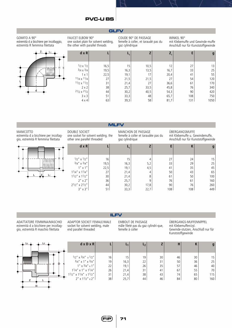
71
PVC-U BS
MLFVMANICOTTOestremita d a bicchiere per incollag-gio, estremità R femmina filettata
DOUBLE SOCKETone socket for solvent welding. the other one parallel threaded
MANCHON DE PASSAGEfemelle à coller et taraudée pas du gaz cylindrique
ÜBERGANGSMUFFEmit Klebemuffe u. Gewindemuffe, Anschluß nur für Kunststoffgewinde
g
15254565
100160260449
L1
1516,319,121,421,425,730,233,3
Z
45,24,5
489
17,822,7
E
27334150617690
108
K
24293543506176
108
L
1619,522,5
2730364451
d x R
1/2” x 1/2”3/4” x 3/4”
1” x 1”11/4” x 11/4”11/2” x 11/2”
2” x 2”21/2” x 21/2”
3” x 3”
ILFVADATTATORE FEMMINA/MASCHIOestremità d a bicchiere per incollag-gio, estremità R maschio filettata
ADAPTOR SOCKET FEMALE/MALEsocket for solvent welding, male end parallel threaded
EMBOUT DE PASSAGEmâle fileté pas du gaz cylindri-que, femelle à coller
ÜBERGANGS-MUFFENNlPPELmit Klebemuffen/zyl. Gewinde-stutzen, Anschluß nur für Kunststoffgewinde
g
15254070
115160
L1
1516,319,121,421,425,7
L2
192226313844
Z
303135414346
K
303646556580
H
465057677484
L
161922263138
d x D x R
1/2” x 3/4” x 1/2”3/4” x 1” x 3/4”
1” x 3/4” x 1”11/4” x 1” x 11/4”
11/2” x 11/4” x 11/2”2” x 11/2” x 2”
GLFVGOMITO A 90°estremità d a bicchiere per incollaggio, estremità R femmina filettata
FAUCET ELBOW 90°one socket plain for solvent welding, the other with parallel threads
COUDE 90° DE PASSAGEfemelle à coller, et taraudé pas du gaz cylindrique
WINKEL 90°mit Klebemuffe und Gewinde-muffe Anschluß nur für Kunststoffgewinde
g
132555
120170340420750
1050
E
27334154617690
108131
L1
1516,319,121,521,425,730,233,339,3
Z
10,513,5
1721,5
2733,540,5
4858
Z1
1216,720,4
2736,645,854,365,781,7
L
16,519,522,5
273138445163
d x R
1/2 x 1/23/4 x 3/4
1 x 111/4 x 11/411/2 x 11/2
2 x 221/2 x 21/2
3 x 34 x 4
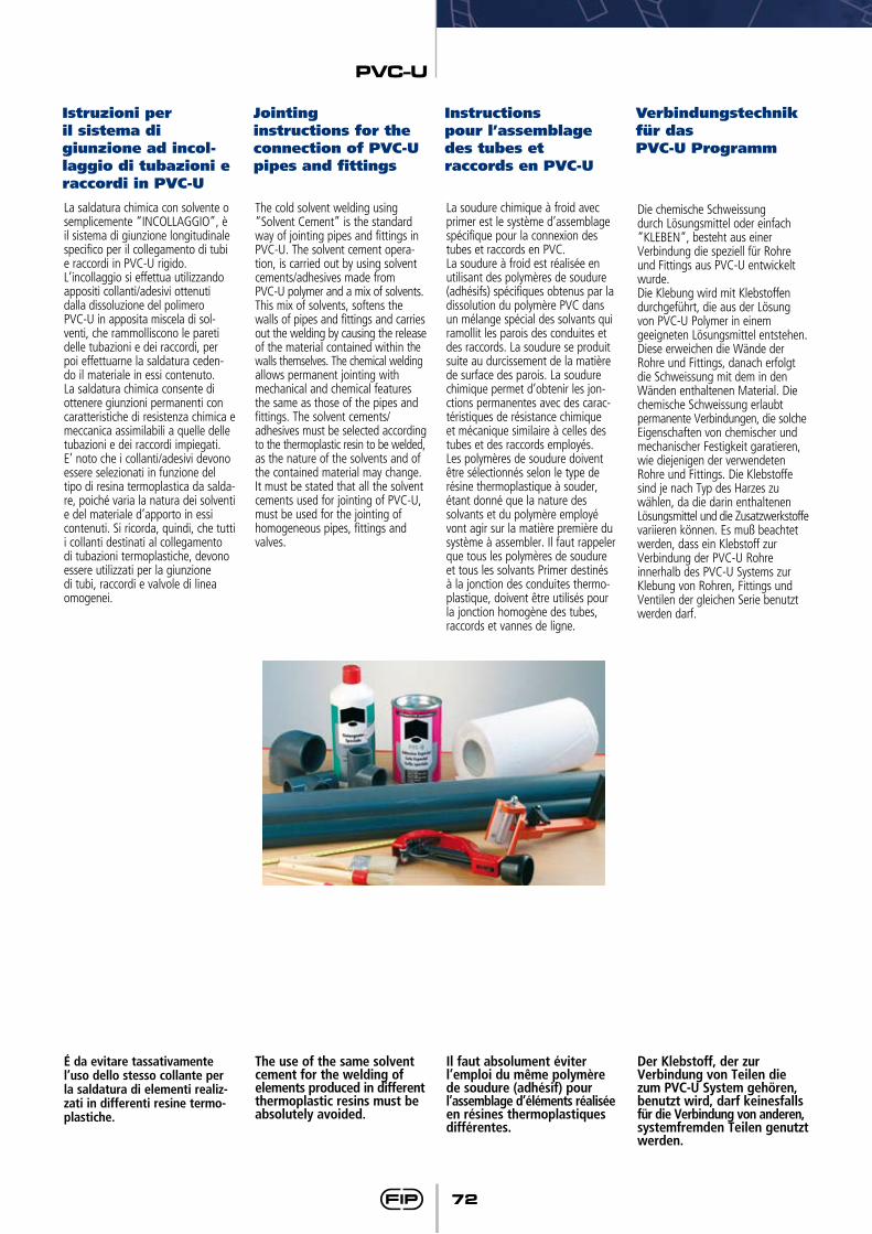
PVC-U
72
La saldatura chimica con solvente o semplicemente “INCOLLAGGIO”, è il sistema di giunzione longitudinale specifico per il collegamento di tubi e raccordi in PVC-U rigido.L’incollaggio si effettua utilizzando appositi collanti/adesivi ottenuti dalla dissoluzione del polimero PVC-U in apposita miscela di sol-venti, che rammolliscono le pareti delle tubazioni e dei raccordi, per poi effettuarne la saldatura ceden-do il materiale in essi contenuto. La saldatura chimica consente di ottenere giunzioni permanenti con caratteristiche di resistenza chimica e meccanica assimilabili a quelle delle tubazioni e dei raccordi impiegati. E’ noto che i collanti/adesivi devono essere selezionati in funzione del tipo di resina termoplastica da salda-re, poiché varia la natura dei solventi e del materiale d’apporto in essi contenuti. Si ricorda, quindi, che tutti i collanti destinati al collegamento di tubazioni termoplastiche, devono essere utilizzati per la giunzione di tubi, raccordi e valvole di linea omogenei.
The cold solvent welding using “Solvent Cement” is the standard way of jointing pipes and fittings in PVC-U. The solvent cement opera-tion, is carried out by using solvent cements/adhesives made from PVC-U polymer and a mix of solvents. This mix of solvents, softens the walls of pipes and fittings and carries out the welding by causing the release of the material contained within the walls themselves. The chemical welding allows permanent jointing with mechanical and chemical features the same as those of the pipes and fittings. The solvent cements/adhesives must be selected according to the thermoplastic resin to be welded, as the nature of the solvents and of the contained material may change. It must be stated that all the solvent cements used for jointing of PVC-U, must be used for the jointing of homogeneous pipes, fittings and valves.
La soudure chimique à froid avec primer est le système d’assemblage spécifique pour la connexion des tubes et raccords en PVC.La soudure à froid est réalisée en utilisant des polymères de soudure (adhésifs) spécifiques obtenus par la dissolution du polymère PVC dans un mélange spécial des solvants qui ramollit les parois des conduites et des raccords. La soudure se produit suite au durcissement de la matière de surface des parois. La soudure chimique permet d’obtenir les jon-ctions permanentes avec des carac-téristiques de résistance chimique et mécanique similaire à celles des tubes et des raccords employés.Les polymères de soudure doivent être sélectionnés selon le type de résine thermoplastique à souder, étant donné que la nature des solvants et du polymère employé vont agir sur la matière première du système à assembler. Il faut rappeler que tous les polymères de soudure et tous les solvants Primer destinés à la jonction des conduites thermo-plastique, doivent être utilisés pour la jonction homogène des tubes, raccords et vannes de ligne.
Die chemische Schweissung durch Lösungsmittel oder einfach “KLEBEN“, besteht aus einer Verbindung die speziell für Rohre und Fittings aus PVC-U entwickelt wurde.Die Klebung wird mit Klebstoffen durchgeführt, die aus der Lösung von PVC-U Polymer in einem geeigneten Lösungsmittel entstehen. Diese erweichen die Wände der Rohre und Fittings, danach erfolgt die Schweissung mit dem in den Wänden enthaltenen Material. Die chemische Schweissung erlaubt permanente Verbindungen, die solche Eigenschaften von chemischer und mechanischer Festigkeit garatieren, wie diejenigen der verwendeten Rohre und Fittings. Die Klebstoffe sind je nach Typ des Harzes zu wählen, da die darin enthaltenen Lösungsmittel und die Zusatzwerkstoffe variieren können. Es muß beachtet werden, dass ein Klebstoff zur Verbindung der PVC-U Rohre innerhalb des PVC-U Systems zur Klebung von Rohren, Fittings und Ventilen der gleichen Serie benutzt werden darf.
É da evitare tassativamente l’uso dello stesso collante per la saldatura di elementi realiz-zati in differenti resine termo-plastiche.
Il faut absolument éviter l’emploi du même polymère de soudure (adhésif) pour l’assemblage d’éléments réalisée en résines thermoplastiques différentes.
The use of the same solvent cement for the welding of elements produced in different thermoplastic resins must be absolutely avoided.
Der Klebstoff, der zur Verbindung von Teilen die zum PVC-U System gehören, benutzt wird, darf keinesfalls für die Verbindung von anderen, systemfremden Teilen genutzt werden.
Istruzioni per il sistema di giunzione ad incol-laggio di tubazioni e raccordi in PVC-U
Jointing instructions for the connection of PVC-U pipes and fittings
Instructions pour l’assemblage des tubes et raccords en PVC-U
Verbindungstechnik für das PVC-U Programm
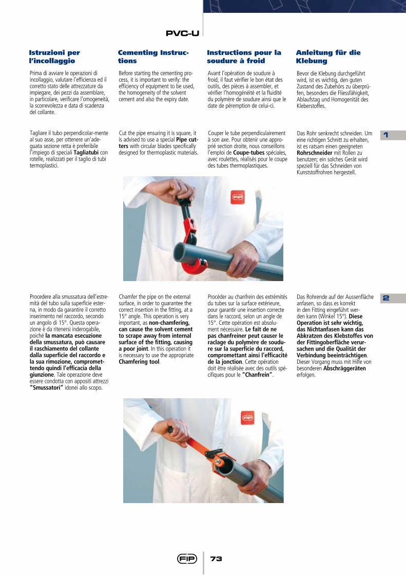
PVC-U
73
Prima di avviare le operazioni di incollaggio, valutare l’efficienza ed il corretto stato delle attrezzature da impiegare, dei pezzi da assemblare, in particolare, verificare l’omogeneità, la scorrevolezza e data di scadenza del collante.
Tagliare il tubo perpendicolar-mente al suo asse, per ottenere un’ade-guata sezione retta è preferibile l’impiego di speciali Tagliatubi con rotelle, realizzati per il taglio di tubi termoplastici.
Procedere alla smussatura dell’estre-mità del tubo sulla superficie ester-na, in modo da garantire il corretto inserimento nel raccordo, secondo un angolo di 15°. Questa opera-zione è da ritenersi inderogabile, poiché la mancata esecuzione della smussatura, può causare il raschiamento del collante dalla superficie del raccordo e la sua rimozione, compromet-tendo quindi l’efficacia della giunzione. Tale operazione deve essere condotta con appositi attrezzi “Smussatori” idonei allo scopo.
Before starting the cementing pro-cess, it is important to verify: the efficiency of equipment to be used, the homogeneity of the solvent cement and also the expiry date.
Cut the pipe ensuring it is square, it is advised to use a special Pipe cut-ters with circular blades specifically designed for thermoplastic materials.
Chamfer the pipe on the external surface, in order to guarantee the correct insertion in the fitting, at a 15° angle. This operation is very important, as non-chamfering, can cause the solvent cement to scrape away from internal surface of the fitting, causing a poor joint. In this operation it is necessary to use the appropriate Chamfering tool.
Avant l’opération de soudure à froid, il faut vérifier le bon état des outils, des pièces à assembler, et vérifier l’homogénéité et la fluidité du polymère de soudure ainsi que le date de péremption de celui-ci.
Couper le tube perpendiculairement à son axe. Pour obtenir une appro-prié section droite, nous conseillons l’emploi de Coupe-tubes spéciales, avec roulettes, réalisés pour le coupe des tubes thermoplastiques.
Procéder au chanfrein des extrémités du tubes sur la surface extérieure, pour garantir une insertion correcte dans le raccord, selon un angle de 15°. Cette opération est absolu-ment nécessaire. Le fait de ne pas chanfreiner peut causer le raclage du polymère de soudu-re sur la superficie du raccord, compromettant ainsi l’efficacité de la jonction. Cette opération doit être réalisée avec des outils spé-cifiques pour le “Chanfrein”.
Bevor die Klebung durchgeführt wird, ist es wichtig, den guten Zustand des Zubehörs zu überprü-fen, besonders die Fliessfähigkeit, Ablaufstag und Homogenität des Kleberstoffes.
Das Rohr senkrecht schneiden. Um eine richtigen Schnitt zu erhalten, ist es ratsam einen geeigneten Rohrschneider mit Rollen zu benutzen; ein solches Gerät wird speziell für das Schneiden von Kunststoffrohren hergestell.
Das Rohrende auf der Aussenfläche anfasen, so dass es korrekt in den Fitting eingeführt wer-den kann (Winkel 15°). Diese Operation ist sehr wichtig, das Nichtanfasen kann das Abkratzen des Klebstoffes von der Fittingoberfläche verur-sachen und die Qualität der Verbindung beeinträchtigen. Dieser Vorgang muss mit Hilfe von besonderen Abschräggeräten erfolgen.
Istruzioni per l’incollaggio
Cementing Instruc-tions
Instructions pour la soudure à froid
Anleitung für die Klebung
1
2
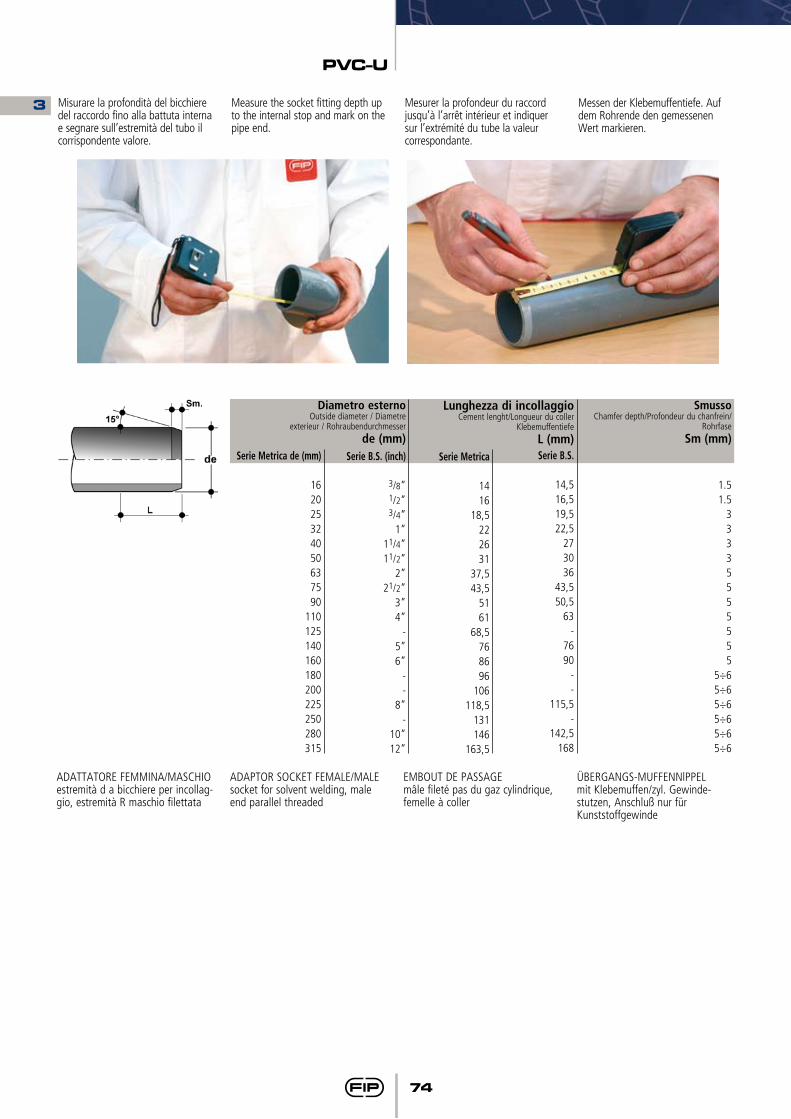
PVC-U
74
Misurare la profondità del bicchiere del raccordo fino alla battuta interna e segnare sull’estremità del tubo il corrispondente valore.
Measure the socket fitting depth up to the internal stop and mark on the pipe end.
Mesurer la profondeur du raccord jusqu’à l’arrêt intérieur et indiquer sur l’extrémité du tube la valeur correspondante.
Messen der Klebemuffentiefe. Auf dem Rohrende den gemessenen Wert markieren.
Serie Metrica
1416
18,5222631
37,543,5
5161
68,5768696
106118,5
131146
163,5
Lunghezza di incollaggioCement lenght/Longueur du coller
KlebemuffentiefeL (mm)Serie B.S.
14,516,519,522,5
273036
43,550,5
63-
7690
--
115,5-
142,5168
SmussoChamfer depth/Profondeur du chanfrein/
RohrfaseSm (mm)
1.51.5
33335555555
5÷65÷65÷65÷65÷65÷6
Diametro esternoOutside diameter / Diametre
exterieur / Rohraubendurchmesserde (mm)
Serie B.S. (inch)
3/8”1/2”3/4”
1”11/4”11/2”
2”21/2”
3”4”
-5”6”
--
8”-
10”12”
Serie Metrica de (mm)
162025324050637590
110125140160180200225250280315
ADATTATORE FEMMINA/MASCHIOestremità d a bicchiere per incollag-gio, estremità R maschio filettata
ADAPTOR SOCKET FEMALE/MALEsocket for solvent welding, male end parallel threaded
EMBOUT DE PASSAGEmâle fileté pas du gaz cylindrique, femelle à coller
ÜBERGANGS-MUFFENNlPPELmit Klebemuffen/zyl. Gewinde-stutzen, Anschluß nur für Kunststoffgewinde
3
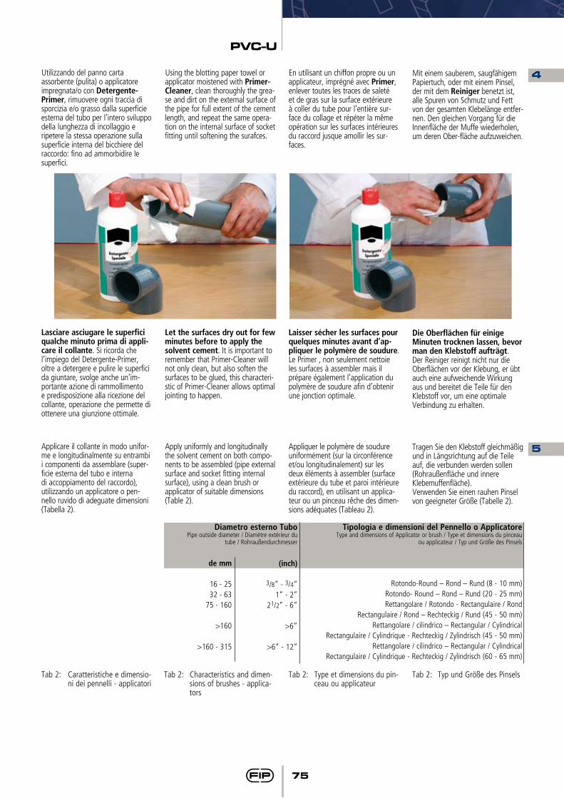
PVC-U
75
Tipologia e dimensioni del Pennello o Applicatore Type and dimensions of Applicator or brush / Type et dimensions du pinceau
ou applicateur / Typ und Größe des Pinsels
Rotondo-Round – Rond – Rund (8 - 10 mm)Rotondo- Round – Rond – Rund (20 - 25 mm)Rettangolare / Rotondo - Rectangulaire / Rond
Rectangulaire / Rond – Rechteckig / Rund (45 - 50 mm)Rettangolare / cilindrico – Rectangular / Cylindrical
Rectangulaire / Cylindrique - Rechteckig / Zylindrisch (45 - 50 mm)Rettangolare / cilindrico – Rectangular / Cylindrical
Rectangulaire / Cylindrique - Rechteckig / Zylindrisch (60 - 65 mm)
Diametro esterno Tubo Pipe outside diameter / Diamètre extérieur du
tube / Rohraußendurchmesser
(inch)
3/8” - 3/4”1” - 2”
21/2” - 6”
>6”
>6” - 12”
de mm
16 - 2532 - 63
75 - 160
>160
>160 - 315
Tab 2: Caratteristiche e dimensio-ni dei pennelli - applicatori
Tab 2: Characteristics and dimen-sions of brushes - applica-tors
Tab 2: Type et dimensions du pin-ceau ou applicateur
Tab 2: Typ und Größe des Pinsels
Utilizzando del panno carta assorbente (pulita) o applicatore impregnata/o con Detergente-Primer, rimuovere ogni traccia di sporcizia e/o grasso dalla superficie esterna del tubo per l’intero sviluppo della lunghezza di incollaggio e ripetere la stessa operazione sulla superficie interna del bicchiere del raccordo: fino ad ammorbidire le superfici.
Lasciare asciugare le superfici qualche minuto prima di appli-care il collante. Si ricorda che l’impiego del Detergente-Primer, oltre a detergere e pulire le superfici da giuntare, svolge anche un’im-portante azione di rammollimento e predisposizione alla ricezione del collante, operazione che permette di ottenere una giunzione ottimale.
Applicare il collante in modo unifor-me e longitudinalmente su entrambi i componenti da assemblare (super-ficie esterna del tubo e interna di accoppiamento del raccordo), utilizzando un applicatore o pen-nello ruvido di adeguate dimensioni (Tabella 2).
Using the blotting paper towel or applicator moistened with Primer-Cleaner, clean thoroughly the grea-se and dirt on the external surface of the pipe for full extent of the cement length, and repeat the same opera-tion on the internal surface of socket fitting until softening the surafces.
Let the surfaces dry out for few minutes before to apply the solvent cement. It is important to remember that Primer-Cleaner will not only clean, but also soften the surfaces to be glued, this characteri-stic of Primer-Cleaner allows optimal jointing to happen.
Apply uniformly and longitudinally the solvent cement on both compo-nents to be assembled (pipe external surface and socket fitting internal surface), using a clean brush or applicator of suitable dimensions (Table 2).
En utilisant un chiffon propre ou un applicateur, imprégné avec Primer, enlever toutes les traces de saleté et de gras sur la surface extérieure à coller du tube pour l’entière sur-face du collage et répéter la même opération sur les surfaces intérieures du raccord jusque amollir les sur-faces.
Laisser sécher les surfaces pour quelques minutes avant d’ap-pliquer le polymère de soudure. Le Primer , non seulement nettoie les surfaces à assembler mais il prépare également l’application du polymère de soudure afin d’obtenir une jonction optimale.
Appliquer le polymère de soudure uniformément (sur la circonférence et/ou longitudinalement) sur les deux éléments à assembler (surface extérieure du tube et paroi intérieure du raccord), en utilisant un applica-teur ou un pinceau rêche des dimen-sions adéquates (Tableau 2).
Mit einem sauberem, saugfähigem Papiertuch, oder mit einem Pinsel, der mit dem Reiniger benetzt ist, alle Spuren von Schmutz und Fett von der gesamten Klebelänge entfer-nen. Den gleichen Vorgang für die Innenfläche der Muffe wiederholen, um deren Ober-fläche aufzuweichen.
Die Oberflächen für einige Minuten trocknen lassen, bevor man den Klebstoff aufträgt.Der Reiniger reinigt nicht nur die Oberflächen vor der Klebung, er übt auch eine aufweichende Wirkung aus und bereitet die Teile für den Klebstoff vor, um eine optimale Verbindung zu erhalten.
Tragen Sie den Klebstoff gleichmäßig und in Längsrichtung auf die Teile auf, die verbunden werden sollen (Rohraußenfläche und innere Klebemuffenfläche).Verwenden Sie einen rauhen Pinsel von geeigneter Größe (Tabelle 2).
4
5
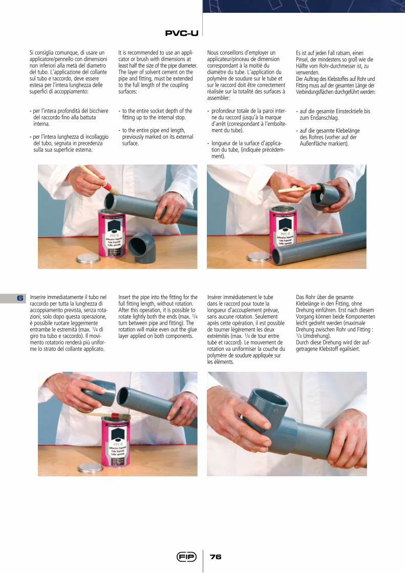
PVC-U
76
Si consiglia comunque, di usare un applicatore/pennello con dimensioni non inferiori alla metà del diametro del tubo. L’applicazione del collante sul tubo e raccordo, deve essere estesa per l’intera lunghezza delle superfici di accoppiamento:
- per l’intera profondità del bicchiere del raccordo fino alla battuta interna.
- per l’intera lunghezza di incollaggio del tubo, segnata in precedenza sulla sua superficie esterna.
Inserire immediatamente il tubo nel raccordo per tutta la lunghezza di accoppiamento prevista, senza rota-zioni; solo dopo questa operazione, è possibile ruotare leggermente entrambe le estremità (max. 1/4 di giro tra tubo e raccordo). Il movi-mento rotatorio renderà più unifor-me lo strato del collante applicato.
It is recommended to use an appli-cator or brush with dimensions at least half the size of the pipe diameter.The layer of solvent cement on the pipe and fitting, must be extended to the full length of the coupling surfaces:
- to the entire socket depth of the fitting up to the internal stop.
- to the entire pipe end length, previously marked on its external surface.
Insert the pipe into the fitting for the full fitting length, without rotation. After this operation, it is possible to rotate lightly both the ends (max. 1/4 turn between pipe and fitting). The rotation will make even out the glue layer applied on both components.
Nous conseillons d’employer un applicateur/pinceau de dimension correspondant à la moitié du diamètre du tube. L’application du polymère de soudure sur le tube et sur le raccord doit être correctement réalisée sur la totalité des surfaces à assembler:
- profondeur totale de la paroi inter-ne du raccord jusqu’à la marque d’arrêt (correspondant à l’emboîte-ment du tube).
- longueur de la surface d’applica-tion du tube, (indiquée précédem-ment).
Insérer immédiatement le tube dans le raccord pour toute la longueur d’accouplement prévue, sans aucune rotation. Seulement après cette opération, il est possible de tourner légèrement les deux extrémités (max. 1/4 de tour entre tube et raccord). Le mouvement de rotation va uniformiser la couche du polymère de soudure appliquée sur les éléments.
Es ist auf jeden Fall ratsam, einen Pinsel, der mindestens so groß wie die Hälfte vom Rohr-durchmesser ist, zu verwenden.Der Auftrag des Klebstoffes auf Rohr und Fitting muss auf der gesamten Länge der Verbindungsflächen durchgeführt werden:
- auf die gesamte Einstecktiefe bis zum Endanschlag.
- auf die gesamte Klebelänge des Rohres (vorher auf der Außenfläche markiert).
Das Rohr über die gesamte Klebelänge in den Fitting, ohne Drehung einführen. Erst nach diesem Vorgang können beide Komponenten leicht gedreht werden (maximale Drehung zwischen Rohr und Fitting : 1/4 Umdrehung). Durch diese Drehung wird der auf-getragene Klebstoff egalisiert.
6
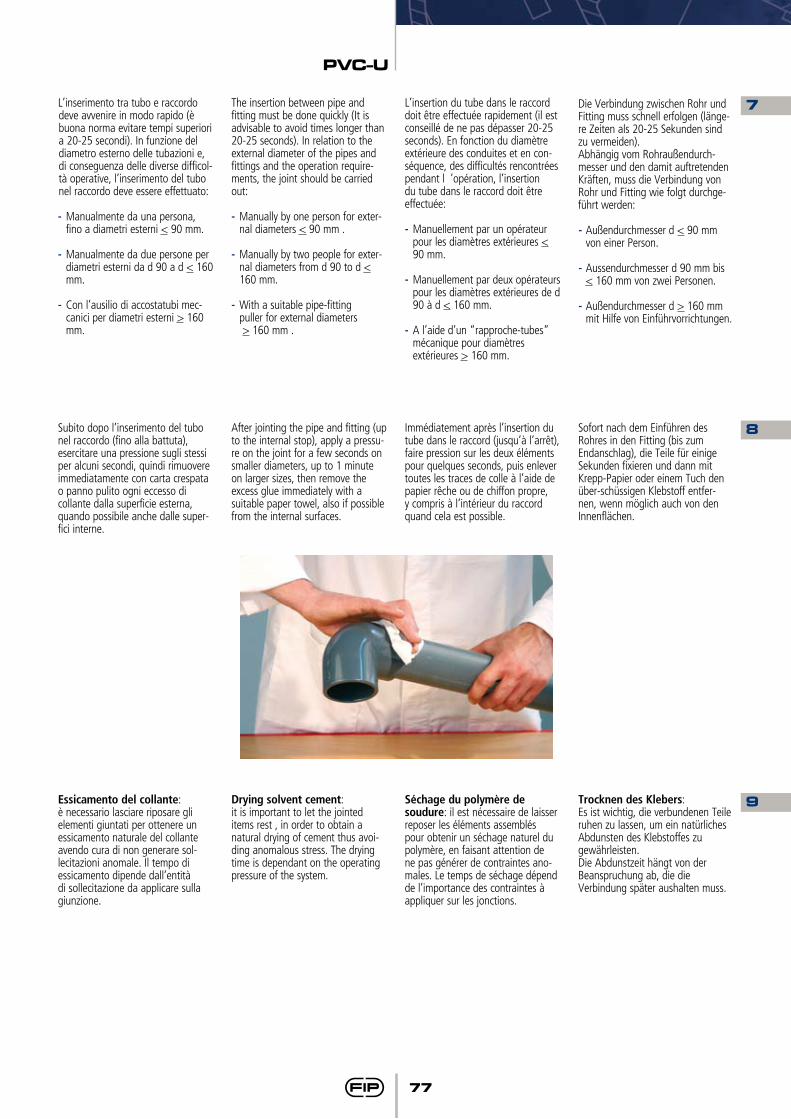
PVC-U
77
L’inserimento tra tubo e raccordo deve avvenire in modo rapido (è buona norma evitare tempi superiori a 20-25 secondi). In funzione del diametro esterno delle tubazioni e, di conseguenza delle diverse difficol-tà operative, l’inserimento del tubo nel raccordo deve essere effettuato:
- Manualmente da una persona, fino a diametri esterni < 90 mm.
- Manualmente da due persone per
diametri esterni da d 90 a d < 160 mm.
- Con l’ausilio di accostatubi mec-canici per diametri esterni > 160 mm.
Subito dopo l’inserimento del tubo nel raccordo (fino alla battuta), esercitare una pressione sugli stessi per alcuni secondi, quindi rimuovere immediatamente con carta crespata o panno pulito ogni eccesso di collante dalla superficie esterna, quando possibile anche dalle super-fici interne.
Essicamento del collante: è necessario lasciare riposare gli elementi giuntati per ottenere un essicamento naturale del collante avendo cura di non generare sol-lecitazioni anomale. Il tempo di essicamento dipende dall’entità di sollecitazione da applicare sulla giunzione.
The insertion between pipe and fitting must be done quickly (It is advisable to avoid times longer than 20-25 seconds). In relation to the external diameter of the pipes and fittings and the operation require-ments, the joint should be carried out:
- Manually by one person for exter-nal diameters < 90 mm .
- Manually by two people for exter-nal diameters from d 90 to d < 160 mm.
- With a suitable pipe-fitting puller for external diameters > 160 mm .
After jointing the pipe and fitting (up to the internal stop), apply a pressu-re on the joint for a few seconds on smaller diameters, up to 1 minute on larger sizes, then remove the excess glue immediately with a suitable paper towel, also if possible from the internal surfaces.
Drying solvent cement: it is important to let the jointed items rest , in order to obtain a natural drying of cement thus avoi-ding anomalous stress. The drying time is dependant on the operating pressure of the system.
L’insertion du tube dans le raccord doit être effectuée rapidement (il est conseillé de ne pas dépasser 20-25 seconds). En fonction du diamètre extérieure des conduites et en con-séquence, des difficultés rencontrées pendant l ’opération, l’insertion du tube dans le raccord doit être effectuée:
- Manuellement par un opérateur pour les diamètres extérieures < 90 mm.
- Manuellement par deux opérateurs pour les diamètres extérieures de d 90 à d < 160 mm.
- A l’aide d’un “rapproche-tubes” mécanique pour diamètres extérieures > 160 mm.
Immédiatement après l’insertion du tube dans le raccord (jusqu’à l’arrêt), faire pression sur les deux éléments pour quelques seconds, puis enlever toutes les traces de colle à l’aide de papier rêche ou de chiffon propre, y compris à l’intérieur du raccord quand cela est possible.
Séchage du polymère de soudure: il est nécessaire de laisser reposer les éléments assemblés pour obtenir un séchage naturel du polymère, en faisant attention de ne pas générer de contraintes ano-males. Le temps de séchage dépend de l’importance des contraintes à appliquer sur les jonctions.
Die Verbindung zwischen Rohr und Fitting muss schnell erfolgen (länge-re Zeiten als 20-25 Sekunden sind zu vermeiden). Abhängig vom Rohraußendurch-messer und den damit auftretenden Kräften, muss die Verbindung von Rohr und Fitting wie folgt durchge-führt werden:
- Außendurchmesser d < 90 mm von einer Person.
- Aussendurchmesser d 90 mm bis < 160 mm von zwei Personen.
- Außendurchmesser d > 160 mm mit Hilfe von Einführvorrichtungen.
Sofort nach dem Einführen des Rohres in den Fitting (bis zum Endanschlag), die Teile für einige Sekunden fixieren und dann mit Krepp-Papier oder einem Tuch den über-schüssigen Klebstoff entfer-nen, wenn möglich auch von den Innenflächen.
Trocknen des Klebers: Es ist wichtig, die verbundenen Teile ruhen zu lassen, um ein natürliches Abdunsten des Klebstoffes zu gewährleisten. Die Abdunstzeit hängt von der Beanspruchung ab, die die Verbindung später aushalten muss.
7
8
9
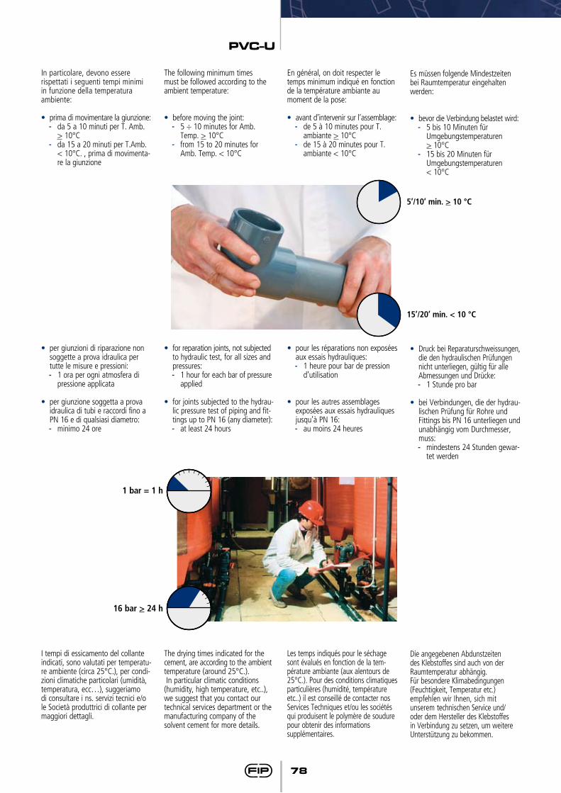
PVC-U
78
In particolare, devono essere rispettati i seguenti tempi minimi in funzione della temperatura ambiente:
• prima di movimentare la giunzione:- da 5 a 10 minuti per T. Amb.
> 10°C- da 15 a 20 minuti per T.Amb.
< 10°C. , prima di movimenta-re la giunzione
• per giunzioni di riparazione non soggette a prova idraulica per tutte le misure e pressioni:- 1 ora per ogni atmosfera di
pressione applicata
• per giunzione soggetta a prova idraulica di tubi e raccordi fino a PN 16 e di qualsiasi diametro: - minimo 24 ore
I tempi di essicamento del collante indicati, sono valutati per temperatu-re ambiente (circa 25°C.), per condi-zioni climatiche particolari (umidità, temperatura, ecc…), suggeriamo di consultare i ns. servizi tecnici e/o le Società produttrici di collante per maggiori dettagli.
The following minimum times must be followed according to the ambient temperature:
• before moving the joint:- 5 ÷ 10 minutes for Amb.
Temp. > 10°C- from 15 to 20 minutes for
Amb. Temp. < 10°C
• for reparation joints, not subjected to hydraulic test, for all sizes and pressures:- 1 hour for each bar of pressure
applied
• for joints subjected to the hydrau-lic pressure test of piping and fit-tings up to PN 16 (any diameter):- at least 24 hours
The drying times indicated for the cement, are according to the ambient temperature (around 25°C.). In particular climatic conditions (humidity, high temperature, etc..), we suggest that you contact our technical services department or the manufacturing company of the solvent cement for more details.
En général, on doit respecter le temps minimum indiqué en fonction de la température ambiante au moment de la pose:
• avant d’intervenir sur l’assemblage:- de 5 à 10 minutes pour T.
ambiante > 10°C- de 15 à 20 minutes pour T.
ambiante < 10°C
• pour les réparations non exposées aux essais hydrauliques:- 1 heure pour bar de pression
d’utilisation
• pour les autres assemblages exposées aux essais hydrauliques jusqu’à PN 16:- au moins 24 heures
Les temps indiqués pour le séchage sont évalués en fonction de la tem-pérature ambiante (aux alentours de 25°C.). Pour des conditions climatiques particulières (humidité, température etc..) il est conseillé de contacter nos Services Techniques et/ou les sociétés qui produisent le polymère de soudure pour obtenir des informations supplémentaires.
Es müssen folgende Mindestzeiten bei Raumtemperatur eingehalten werden:
• bevor die Verbindung belastet wird:- 5 bis 10 Minuten für
Umgebungstemperaturen > 10°C- 15 bis 20 Minuten für
Umgebungstemperaturen < 10°C
• Druck bei Reparaturschweissungen, die den hydraulischen Prüfungen nicht unterliegen, gültig für alle Abmessungen und Drücke:- 1 Stunde pro bar
• bei Verbindungen, die der hydrau-lischen Prüfung für Rohre und Fittings bis PN 16 unterliegen und unabhängig vom Durchmesser, muss: - mindestens 24 Stunden gewar-
tet werden
Die angegebenen Abdunstzeiten des Klebstoffes sind auch von der Raumtemperatur abhängig. Für besondere Klimabedingungen (Feuchtigkeit, Temperatur etc.) empfehlen wir Ihnen, sich mit unserem technischen Service und/oder dem Hersteller des Klebstoffes in Verbindung zu setzen, um weitere Unterstützung zu bekommen.
5’/10’ min. > 10 °C
15’/20’ min. < 10 °C
1 bar = 1 h
16 bar > 24 h
PVC-U
79
• Nel caso in cui il diametro esterno del tubo e il diametro interno del raccordo sono agli estremi oppo-sti dei loro valori di tolleranza, il tubo asciutto non può essere inserito nel bicchiere asciutto del raccordo. L’operazione di inseri-mento sarà possibile solo dopo avere applicato l’abbinamento Detergente e Collante su entram-bi i componenti da saldare.
• Il collante viene realizzato con la stessa resina di PVC che si utilizza per la produzione di tubi raccordi e valvole. Se non diversamente specificato, il collante impiegato per le superfici da giuntare, deve essere utilizzabile con le seguenti tolleranze: - Interferenza max di 0,2 mm.- Tolleranza di gioco max. 0,6
mm.
• Durante l’impiego del Collante e del Detergente si consiglia di attenersi alle seguenti avvertenze:
• Utilizzare guanti e occhiali di sicu-rezza per la protezione di mani e occhi.
• Utilizzare il Collante e detergente in ambienti di lavoro con suffi-ciente ventilazione per evitare la formazione di sacche d’aria contenenti concentrazioni di sol-venti evaporati, i quali potrebbero procurare irritazioni alle vie respi-ratorie ed agli organi visivi.
• Causa la volatilità dei solventi contenuti nel collante e deter-gente, si ricorda che i contenitori devono essere rinchiusi immedia-tamente dopo l’uso.
• I solventi in fase gassosa hanno la tendenza a formare miscele infiammabili, per cui si racco-manda di eliminare dalle aree di lavoro eventuali fonti di innesco di fiamma, quali: operazioni di saldatura, accumuli di cariche elettrostatiche e si ricorda di non fumare. In ogni caso si consiglia di attenersi scrupolosamente alle avvertenze prescritte dai pro-duttori di collante indicate sulle confezioni.
• If the external diameter of the pipe and the internal diameter of the fitting are at the two opposite ends of the their values of tole-rance, the dried pipe cannot be inserted into the dried socket of the fitting. The insertion will only be possible after applying both the Cleaner and Adhesive on the pipe and fitting to be welded.
• The adhesive is made with the same PVC resin that it’s used for the production of pipes, fittings and valves. Unless otherwise spe-cified, the glue for the surfaces to joint must be used with the following tolerances:- Max interferences of 0,2 mm.- Max clearance tolerance: 0,6
mm.
• When using the Adhesive and the Cleaner we recommend you follow the following instructions:
• Use protective gloves and glasses to protect hands and eyes.
• Use the Adhesive and the Cleaner in places with enough ventilation to avoid the formation of air pockets containing concentrations of evaporated solvents that might irritate breathing or eyes.
• Because of the volatile nature of the solvents contained in the adhesive and in the cleaner, ple-ase remember that the tins must be closed immediately after use.
• The solvents in their gaseous phase tend to form flammable mixtures, therefore it is recommendable to eliminate from the working place any source able to start a fire such as: welding operations, storage of electrostatic charge or smoking. In any case please carefully follow the instructions given by the manufacturers and indicated on the packaging.
• Dans le cas où le diamètre extérieure du tube et le diamètre intérieure du raccord se trouvent aux extrémités opposées de leurs valeurs de tolérance, le tube sec ne peut pas être inséré dans le man-chon sec du raccord. L’opération d’insertion sera possible seulement après avoir appliqué la combinai-son Primer et Polymère de Soudure sur les deux éléments à souder.
• Le polymère de soudure est pro-duit avec la résine en PVC utilisée pour la production des tubes, raccords et vannes.
Le polymère de soudure doit être employé avec les tolérances entre tubes et raccords suivantes:- Interférences max. de 0,2 mm.- Tolérances max.. de jeu 0,6
mm.
• Pendent l’utilisation du Polymère de Soudure et du Primer, il est conseillé de suivre les instructions suivantes:
• Utiliser des gants et des lunettes pour la protection des mains et des yeux.
• Utiliser le Polymère de Soudure et le Primer dans des lieux de travail ayant une aération suffisante pour éviter des concentrations de solvants évaporés, qui peuvent provoquer des irritations des voies respiratoires et des organes de la vue.
• De par la volatilité des solvants contenus dans le polymère de soudure et le primer, tous les récipients doivent être refermés immédiatement après leur utilisa-tion
• Les solvants dans leur phase gazéiforme ont tendance à former des mélanges inflammables, c’est pourquoi nous conseillons d’éliminer toutes les sources qui peuvent amorcer une incendie, comme par exemple les opérations de soudure et les accumulations de charges électrostatiques. Il ne faut pas fumer. Dans tous les cas, nous conseillons de suivre scrupuleu-sement les instructions données par les fabricants du polymère de soudure sur les notices d’emploi.
• Falls sich der Rohraussen-durchmesser und der Innendurch-messer des Fittings an der Grenze des Toleranzbereiches befindet, darf das trockene Rohr nicht in die trockene Klebemuffe einge-steckt werden. Das Einführen ist erst möglich, nachdem Reiniger und Klebstoff auf die beiden zu verbindenden Teile aufgetragen wurde.
• Der Klebstoff wird aus dem glei-chen Harz, wie das PVC-U her-gestellt, das FIP für die Fertigung von Rohren, Fittings und Ventilen des PVC-U Systems verwendet. Falls nicht anders angegeben, muss der Klebstoff folgende Toleranzen abdecken: - Max. Übermaß: 0,2 mm. - Max. Spalt: 0,6 mm.
• Bei der Verwendung des Klebstoffes und des Reinigers, ist es ratsam, die folgenden Anweisungen zu beachten:
• Sicherheitshandschuhe und -bril-len zum Schutz von Augen und Händen tragen.
• Der Klebstoff und der Reiniger sind nur in Räumen mit ausrei-chender Belüftung zu verwenden (diese Substanzen reizen die Atemwege und die Augen).
• Wegen der Flüchtigkeit der im Klebstoff und Reiniger enthalte-nen Lösungsmittel, ist es wichtig, die Behälter sofort nach dem Gebrauch zu schließen.
• Die Lösungsmittel in gasförmiger Phase neigen dazu, brennbare Gase zu bilden. Deswegen müssen alle möglichen Brandquellen entfernt bzw. vermieden werden, wie z.B. Schweißungsoperationen, elektrostatische Aufladung und Rauchen. Die vom Hersteller des Klebstoffs auf der Verpackung vorgeschriebenen Anweisungen sind zu beachten.
Note, raccomanda-zioni ed avvertenze generali
Notes, recommen-dations and general instructions
Notes, recommanda-tions et instructions generales
Bemerkungen, em-pfehlungen und al-lgemeine hinweise
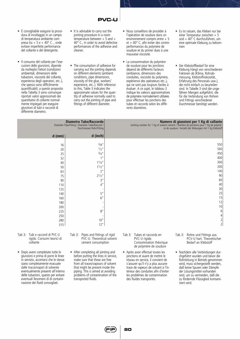
PVC-U
80
• É consigliabile eseguire la proce-dura di incollaggio in un campo di temperatura ambiente com-presa tra + 5 e + 40° C. , onde evitare imperfette performance del collante e del detergente.
• Il consumo del collante per l’ese-cuzioni delle giunzioni, dipende da molteplici fattori (condizioni ambientali, dimensioni delle tubazioni, viscosità del collante, esperienza degli operatori, etc..), che spesso sono difficilmente quantificabili; a questo proposito nella Tabella 3 sono comunque riportati valori approssimati dei quantitativi di collante normal-mente impiegati per eseguire giunzioni di tubi e raccordi di differente diametro.
Tab 3: Tubi e raccordi di PVC-U rigido. Consumi teorici di collante
• Dopo avere completato tutte le giunzioni e prima di porre le linee in servizio, accertarsi che le stesse siano completamente evacuate dalle tracce/vapori di solvente eventualmente presenti all’interno delle tubazioni, questo per evitare eventuali fenomeni di di contami-nazione dei fluidi convogliati.
• It is advisable to carry out the jointing procedure in a room temperature between + 5 and + 40° C., in order to avoid defective performances of the adhesive and cleaner.
• The consumption of adhesive for carrying out the jointing depends on different elements (ambient conditions, pipe dimensions, viscosity of the glue, workers’ experience, etc..). With reference to this, Table 3 indicates the approximate values for the quan-tity of adhesive normally used to carry out the jointing of pipe and fittings of different diameter.
Tab 3: Pipes and fittings of rigid PVC-U. Theoretical solvent cement consumption
• After completing all jointing and before putting the lines in service, make sure that these are free from all traces/vapours of solvent that might be present inside the piping. This is aimed at avoiding problems of contamination of the transported fluids.
• Nous conseillons de procéder à l’opération de soudure dans un environnement compris entre + 5 et + 40° C, afin éviter des contre-performances du polymère de soudure et du primer dues à une mauvaise viscosité.
• La consommation du polymère de soudure pour les jonctions dépend de différents facteurs (ambiance, dimensions des conduites, viscosité du polymère, expérience des opérateurs etc..), qui ne sont pas toujours faciles à évaluer. A ce sujet, le tableau 3 indique les valeurs approximatives de polymère normalement utilisées
pour effectuer les jonctions des tubes et raccords selon les diffé-rents diamètres.
Tab 3: Tubes et raccords en PVC-U rigide.
Consommation théorique de polymère de soudure
• Après avoir effectué toutes les jonctions et avant de mettre le réseau en service, il convient de s’assurer qu’il n’y a plus aucune trace de vapeurs de solvant à l’in-térieur des conduites afin d’éviter les problèmes de contamination des fluides transportés.
• Es ist ratsam, das Kleben nur bei einer Temperatur zwischen + 5 und + 40° C durchzuführen, um eine optimale Klebung zu bekom-men
• Der Klebstoffbedarf für eine Klebung hängt von verschiedenen Faktoren ab (Klima, Rohrab-messung, Klebstoffviskosität, Erfahrung des Personals usw.), die nicht einfach zu beurteilen sind. In Tabelle 3 sind die unge-fähren Mengen aufgeführt, die für die Verbindung von Rohren und Fittings verschiedener Durchmesser benötigt werden.
Tab 3: Rohre und Fittings aus PCV-U hart. Theoretischer Bedarf an Klebstoff
• Nachdem alle Verbindungen dur-chgeführt wurden und bevor die Rohrleitung in Betrieb genommen wird, muss sichergestellt werden, daß keine Spuren oder Dämpfe der Lösungsmittel vorhanden sind, um zu vermeiden, daß die zu fördernde Flüssigkeit kontami-niert wird.
Numero di giunzioni per 1 Kg di collante Jointing number for 1 Kg of solvent cement / Nombre de jonctions pour 1 Kg de polymè-
re de soudure / Anzahl der Klebungen mit 1 Kg Klebstoff
550500450400300200140
9060403025151210
6422
Diametro Tubo/Raccordo Diameter Pipe/Fitting / Diamètre Tube/Raccord /
Durchmesser Rohr/Fitting
d (inch)
3/8”1/2”3/4”
1”11/4”11/2”
2”21/2”
3”4”
-5”6”
--
8”-
10”12”
d (mm)
162025324050637590
110125140160180200225250280315
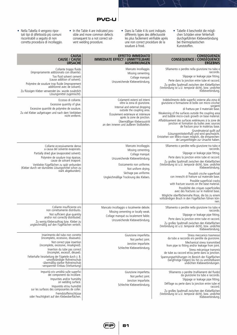
PVC-U
81
• Nella Tabella 4 vengono ripor-tati tipi di difettosità più comuni riscontrabili a seguito di non corretta procedura di incollaggio.
• In the Table 4 are indicated pos-sible and more common defects consequent to a not correct sol-vent welding procedure.
• Dans la Table 4 ils sont indiqués différents types des défectuosité les plus facilement vérifiable après une non correct procédure de la soudure à froid.
• Tabelle 4 beschreibt die mögli-chen Schäden einer fehlerhaft durchgeführten Klebeverbindung bei thermoplastischen Kunststoffen.
CAUSACAUSE / CAUSE
URSACHE
Collante troppo fluido (impropriamente addizionato con diluente).
Too fluid solvent cement (cause addition of solvent).
Polymère de soudure trop fluide (improprement additionné avec de solvant).
Zu flüssigen Kleber verwendet (ev. wurde zusätzlich Lösungsmittel zugemischt).
Eccesso di collante.Excessive quantity of glue.
Excessive quantité de polymère de soudure.Zu viel Kleber aufgetragen und nach dem Verkleben
nicht entfernt.
Collante eccessivamente denso a causa del solvente evaporato.
Partially dried glue (evaporated solvent).Polymère de soudure trop épaisse,
cause de solvant évaporé.Verklebte Fügeflächen zu spät verbunden
(Kleber durch ver-dunstetes Lösungsmittel schon zu stark abgebunden).
Collante insufficiente e/o non correttamente distribuito.
Not sufficient glue quantity and/or not correctly distributed.
Zu wenig Kleberauftrag bzw. Kleber zu ungleichmäßig auf den Fügeflächen verteilt.
Inserimento del tubo non corretto (incompleto, eccessivo, disassato).
Not correct pipe insertion (incomplete, excessive, misaligned).
Insertion du tube pas correct (incomplet, excessif, désaxé).
Fehlerhafte Verarbeitung der Fügeteile durch z. B.-unvollständiger Rohreinschub
-übermäßig starker Rohreinschub-verspannter Einbau (Verkantung)
Impurità e/o umidità sulle superfici dei componenti da incollare.
Impurities and/or humidity on welding surface.
Impuretés et/ou humidité sur les surfaces des composantes de coller.
Fremdstoffeinschlüsse oder Feuchtigkeit auf den Klebeoberflächen.
EFFETTO IMMEDIATOIMMEDIATE EFFECT / UNMITTELBARE
AUSWIRKUNGEN
Mancato incollaggio.Missing cementing.
Collage manqué.Unzureichende Klebeverbindung.
Colamenti esterni ed interni oltre la zona di giunzione.
Internal and external dropping outside the coupling area.
Écoulement extérieure et intérieure après la zone de jonction.
Übermäßiger Kleberaustritt an den inneren und äußeren Stoßstellen.
Mancato incollaggio.Missing cementing.
Collage manqué.Unzureichende Klebeverbindung.
Essicamento non uniforme.
Not uniform drying.Séchage pas uniforme.
Ungleichmäßige Trocknung des Klebers.
Mancato incollaggio o localmente debole. Missing cementing or locally weak.
Collage manqué ou localement faible.Unzureichende Klebeverbindung.
Giunzione imperfetta.Not perfect joint.
Jonction imparfaite.Schlechte Klebeverbindung.
Giunzione imperfetta.Not perfect joint.
Jonction imparfaite.Schlechte Klebeverbindung.
CONSEGUENZACONSEQUENCE / CONSÉQUENCE
ERGEBNIS
Sfilamento o perdite nella giunzione tra tubo e raccordo.
Slippage or leakage pipe fitting.Perte dans la jonction entre tube et raccord.
Zu großes Spaltmaß zwischen den Klebeflächen (Verbindung ist u.U. temporär dicht), bzw. undichte
Klebeverbindung.
Indebolimento delle superfici esterne alla zona di giunzione e formazione di bolle con micro-cricche/
sorgenti di frattura per il materiale base.
Weakening of the surfaces outside the coupling area and bubble micro-crack growth on base material.
Affaiblissement des surfaces extérieures à la zone de jonction et formation du bulles avec sources
de fracture pour le matériau base.Grundmaterial quillt auf
(Lösungsmitteleinfluß) und wird geschwächt. Entstehen von Mikro-rissen möglich, die entsprechen-
de Langzeitfolgen zur Ursache haben.
Sfilamento o perdite nella giunzione tra tubo e raccordo.
Slippage or leakage pipe fitting.Perte dans la jonction entre tube et raccord.
Zu großes Spaltmaß zwischen den Klebeflächen (Verbindung ist u.U. temporär dicht), bzw. undichte
Klebeverbindung.
Possibili cricche superficiali con inneschi di fratture sul materiale base.
Possible superficial cracks with fracture sources on the base material.
Possibilité des criques superficielles avec des fractures sur le matériel base.
Mögliche oberflächennahe Risse, die bis zu einem vollständigen Bruch in den Fügeflächen führen kön-
nen.
Sfilamento o perdite nella giunzione tra tubo e raccordo.
Slippage or leakage pipe fitting.Perte dans la jonction entre tube et raccord.
Zu großes Spaltmaß zwischen den Klebeflächen (Verbindung ist u.U. temporär dicht), bzw. undichte
Klebeverbindung.
Stress meccanico trasmesso da tubo a raccordo e/o perdite da giunzione.
Mechanical stress transmitted from pipe to fitting and/or leakage from joint.
Stress mécanique transmis de tube au raccord et/ou perte dans la jonction.
Spannungserhöhungen im Bereich der Fügeflächen (langfristige Folgen) bis hin zu unmittelbaren
undichten Klebeverbindungen.
Sfilamento o perdite (trafilamenti del fluido) da giunzione tra tubo e raccordo.
Slippage or leakage pipe fitting.Défilage ou perte dans la jonction entre tube et
raccord.Zu großes Spaltmaß zwischen den Klebeflächen
(Verbindung ist u.U. temporär dicht), bzw. undichte Klebeverbindung.
Raccordi in PVC-U
PVC-U fittings
Raccords en PVC-U
Fittings aus PVC-U
FIPFormatura
Iniezione Polimeri
Loc. Pian di Parata 16015 Casella Genova Italytel. +39 010 9621.1 fax +39 010 [email protected]
Raccordi in PVC-UU-PVC fittingsRaccords en PVC-UFittings aus PVC-U
01
/20
09
Since 1954 FIP produces injection moulded valves and fittings in thermoplastic materials for pressure pipeline systems thus becoming nowadays the la rges t European va lves manufacturer. F IP i s a company o f the Aliaxis Group: a worldwide industrial holding gathering together a series of companies manufacturing and marketing plastic plumbing products for building industrial and public utilities applications.FIP products are manufactured on EU production sites, operating to the Quality Assurance System in compliance with ISO 9001 and with the Environmental Management System ISO 14001 standards requirements. In FIP products there are over 50 years of know-how powered by a strong quest for innovation.
01
/20
09
Distributed by
PV
C-U
fit
tin
gs