digital storage oscillators
DESCRIPTION
A discussion on Digital Storage Oscillators.TRANSCRIPT
DIGITAL STORAGE OSCILLOSCOPE
DSO
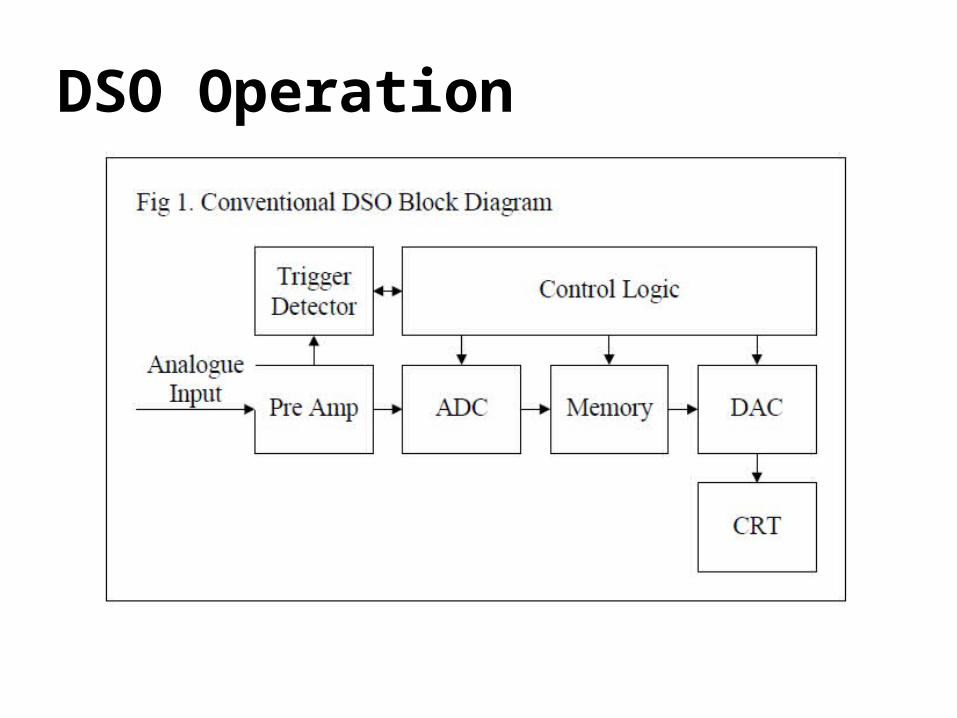
DSO Operation
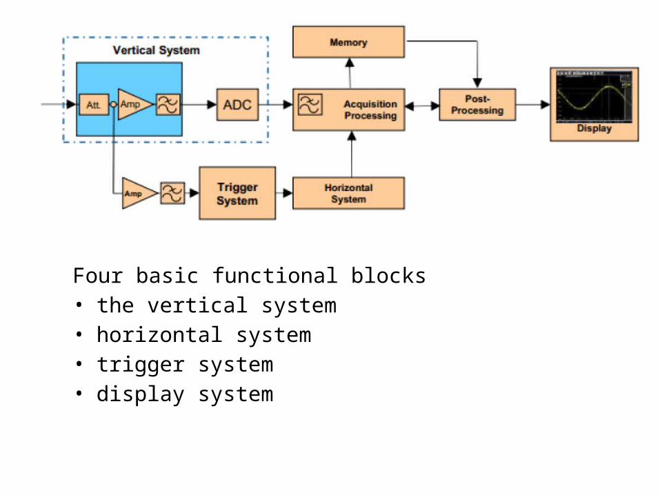
Four basic functional blocks• the vertical system• horizontal system• trigger system• display system
The Vertical System• allows the user to position and scale the waveform
vertically, select a value for input coupling, as well as modify signal characteristics to make them appear a certain way on the display.
• The user can vertically place the waveform at a precise position on the display and increase or decrease its size.
• All oscilloscope displays have a grid that divides the viewable area into 8 or 10 vertical divisions, each of which represents a portion of the total voltage.
The Horizontal System• is more directly related to signal acquisition than is
the vertical system, and stresses performance metrics such as sample rate and memory depth, as well as others that are directly related to the acquisition and conversion of the signal.
The acquisition mode menu on a typical oscilloscope is very limited with only one waveform per channel.
Some oscilloscopes can show three waveforms per channel in parallel, and decimation type and waveform arithmetic types can be combined for each waveform.
Typical modes include:• Sample mode: A waveform point is created with one sample
for each waveform interval.• High Res mode: an average of the samples in the waveform
interval is displayed for each interval.• Peak detect mode: The minimum and maximum of the sample
points within a waveform are displayed for each interval.• RMS: The RMS value of the samples within the waveform
interval are displayed. This is proportional to the instantaneous power.
Typical waveform arithmetic modes include:
• Envelope mode: Based on the waveforms captured from a minimum of two trigger events, the oscilloscope creates a boundary (envelope) that represents the highest and lowest values of a waveform.
• Average mode: The average of each waveform interval sample is formed over a number of acquisitions
The Trigger System
is one of the fundamental elements of every digital oscilloscope as it captures signal events for detailed analysis and provides a stable view of repeating waveforms.
The accuracy of a trigger system as well as its flexibility determine how well the measurement signal can be displayed and analyzed.
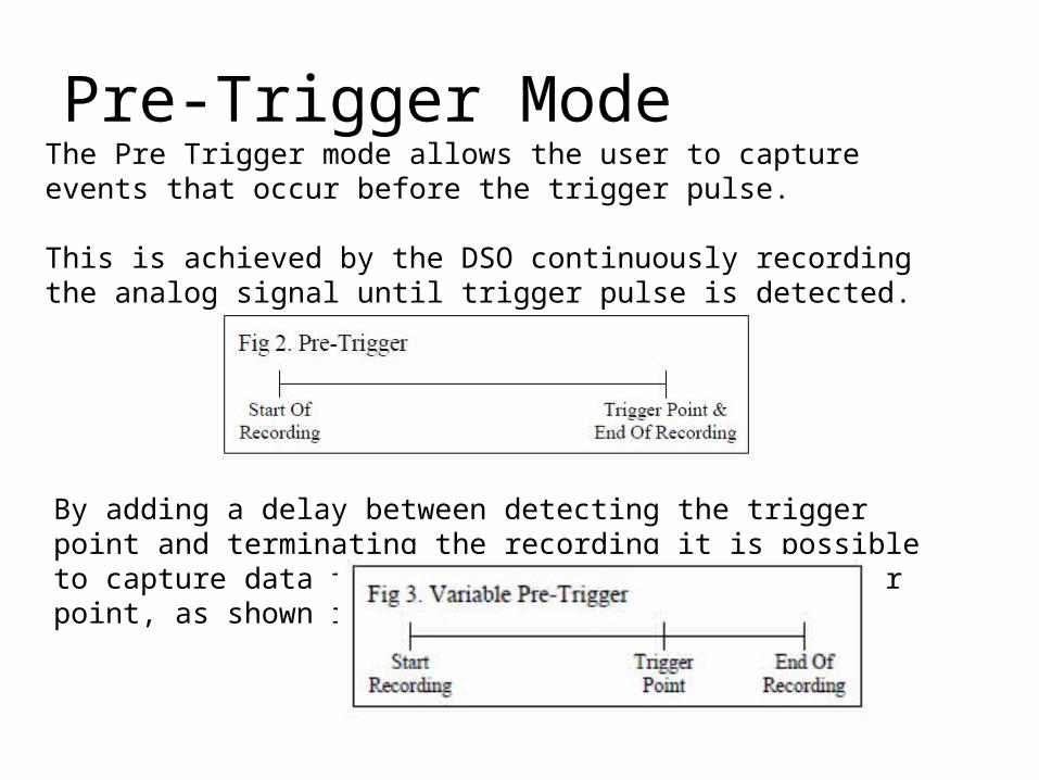
Pre-Trigger ModeThe Pre Trigger mode allows the user to capture events that occur before the trigger pulse.
This is achieved by the DSO continuously recording the analog signal until trigger pulse is detected.
By adding a delay between detecting the trigger point and terminating the recording it is possible to capture data from before and after the trigger point, as shown in fig 3.
The Display system and User Interface
• Controls all aspects of the signal›s presentation to the user. • The display’s grid markings together form a grid called a
graticule or reticle. • Digital oscilloscopes and the tasks they perform are complex,
so the user interface must be both comprehensive yet comprehensible.
Types of Digital OscilloscopesThere are a variety of digital oscilloscopes and those described here are the
most common today.
• Digital Sampling Oscilloscopes– samples the signal before any signal conditioning such as attenuation
or amplification is performed.– Its design allows the instrument to have very broad bandwidth,
although with somewhat limited dynamic range of about 1 V peak-to-peak.
• Real-Time Sampling Oscilloscopes– The benefits of real-time sampling become apparent when the
frequency range of a signal is less than half that of an oscilloscope’s maximum sample rate.
• Mixed-Signal Oscilloscope– Includes logic and protocol analysis, which simplifies the test bench
and allows synchronous visualization of analog waveforms, digital signals, and protocol details within a single instrument.
Advantages over the analog oscilloscope are:• Brighter and bigger display with color to distinguish multiple traces• Equivalent time sampling and averaging across consecutive samples or
scans lead to higher resolution down to µV• Peak detection• Easy pan and zoom across multiple stored traces allows beginners to work
without a trigger– This needs a fast reaction of the display (some oscilloscopes have 1 ms
delay)– The knobs have to be large and turn smoothly
• Also slow traces like the temperature variation across a day can be recorded
• Allows for automation.
Disadvantage of digital oscilloscopes• limited refresh rate of the screen. • It is sometimes difficult to spot "glitches" or other rare phenomena on
the black-and-white screens of standard digital oscilloscopes;