digital process transmitter - hidroteka · 9 belt weigher operating mode ... belt calibration ......
TRANSCRIPT
NU-eNod4B-E-0416_236703-A.doc
SCAIME SAS – Technosite Altéa – 294, Rue Georges Charpak – 74100 JUVIGNY - FRANCE Tél. : +33 (0)4 50 87 78 64 – www.scaime.com
eNod4-B Digital Process Transmitter
Ch
ara
cteri
stic
s an
d f
un
ctio
nin
g

2/34
User manual SCAIME: NU-eNod4B-E-0416_236703-A.doc
1 ENOD4 PRODUCT RANGE ....................................................................................... 4
1.1. General presentation .................................................................................... 4
1.2. Versions and options .................................................................................... 4
1.2.1 Versions ....................................................................................................... 4
1.2.2 IO+ Option .................................................................................................. 4
1.3. eNodView Software ...................................................................................... 4
2 GENERAL CHARACTERISTICS .................................................................................. 5
2.1. Dimensions ..................................................................................................... 5
2.2. Characteristics .............................................................................................. 6
3 CONNECTIONS ........................................................................................................ 8
3.1. Power supply connection........................................................................... 10
3.2. Load-cell wiring ........................................................................................... 10
3.3. IO+ option .................................................................................................... 10
3.4. Inputs / outputs connections ..................................................................... 12
3.4.1. Typical connections ............................................................................. 12
4 COMMUNICATION ................................................................................................ 13
4.1. Communication Interface connections ................................................... 13
4.1.1 Process control communication .......................................................... 13
4.1.2 PC communication ................................................................................ 14
4.1.3 AUX Communication (for HMI) ............................................................. 14
4.2. Communication address selection ........................................................... 15
4.3. Communication rate selection .................................................................. 15
4.4. Protocoles de communication .................................................................. 16
4.5. Simultaneous functioning of communications ......................................... 16
4.5.1 Standard version .................................................................................... 16
4.5.2 Profibus version ...................................................................................... 17
5 CALIBRATION AND SCALE ADJUSTMENT ............................................................. 18
5.1. Physical calibration..................................................................................... 18
5.2. Theoretical calibration ................................................................................ 18
5.3. Scale adjustment coefficient ..................................................................... 18
5.4. Gravity correction ....................................................................................... 18
5.5. Scale interval ............................................................................................... 18
6 FILTERS .................................................................................................................... 19
6.1. Filtering related to the A/D conversion rate ............................................. 19
6.2. Bessel low pass filter.................................................................................... 19
6.3. Notch filter .................................................................................................... 19
6.4. Moving average filter ................................................................................. 19
7 INPUTS FUNCTIONING ........................................................................................... 20
7.1. Inputs assignment: ...................................................................................... 20
7.2. General functions ........................................................................................ 20
7.2.1 None .......................................................................................................... 20
7.2.2 Tare ........................................................................................................... 20
7.2.3 Cancel tare ................................................................................................. 20
7.2.4 Zero ........................................................................................................... 20
7.2.5 Transmit measurement ............................................................................... 21
7.2.6 Measurement window ................................................................................ 21
7.2.7 Sensor input control .................................................................................... 21
7.3. Functions attached to an operating mode: ............................................. 22
8 OUTPUTS FUNCTIONING ........................................................................................ 23

3/34
User manual SCAIME: NU-eNod4B-E-0416_236703-A.doc
8.1. Outputs assignment: ................................................................................... 23
8.2. General functions: ....................................................................................... 23
8.2.1 None: ....................................................................................................... 23
8.2.2 Set point: ................................................................................................. 23
8.2.3 Motion: .................................................................................................... 24
8.2.4 Defective measurement: ...................................................................... 24
8.2.5 Input image: ........................................................................................... 24
8.2.6 Level on request: .................................................................................... 24
8.3. Functions attached to an operating mode: ............................................. 24
8.4. Optional analog output (IO+ version) ....................................................... 24
9 BELT WEIGHER OPERATING MODE ........................................................................ 26
9.1. Introduction and Overview ........................................................................ 26
9.2. Totalization cycle description .................................................................... 27
9.2.1 Cycle options ......................................................................................... 27
• Batch mode ...................................................................................................... 27
• Clear totalization .............................................................................................. 28
• PID Activation ................................................................................................... 28
9.2.2 Weight section length (mm) ................................................................. 28
9.2.3 Conveyor inclination (degrees) ........................................................... 29
9.2.4 Minimum load to totalize (weight unit/meter) .................................... 29
9.2.5 Pulses factor speed sensor (Pulses/meter) .......................................... 29
9.2.6 Measurement time factor for speed (x250ms).................................... 29
9.2.7 Constant belt speed (m/s) .................................................................... 30
9.2.8 Flow correction factor ........................................................................... 30
9.3. Belt calibration ............................................................................................ 30
9.3.1 Speed sensor calibration ...................................................................... 30
9.3.2 Static weight calibration ....................................................................... 30
9.3.3 Material Test (Dynamic weight calibration or correction factor) ...... 31
9.4. Calibration of flow rate ............................................................................... 31
9.5. Totalization ................................................................................................... 31
9.6. Alarms .......................................................................................................... 31
9.6.1 Minimum flow rate limit value (0.1%) ................................................... 31
9.6.2 Maximum flow rate limit value (0.1%) ................................................. 32
9.6.3 Minimum belt load limit value (0.1%) .................................................. 32
9.6.4 Maximum belt load limit value (0.1%) ................................................. 32
9.6.5 Minimum control output limit value (0.1%).......................................... 32
9.6.6 Maximum control output limit value (0.1%) ........................................ 32
9.6.7 Minimum belt speed limit value (0.1%) ............................................... 33
9.6.8 Maximum belt speed limit value (0.1%) .............................................. 33
9.6.9 Inhibit time of speed alarms at start (ms) ............................................ 33
9.6.10 Inhibit time of speed alarms in service (ms) ..................................... 33
9.6.11 Errors counter........................................................................................ 33
9.7. Inputs assignments ...................................................................................... 34
• Start / Stop dosing (and batch) ...................................................................... 34
• Belt running motion detection ........................................................................ 34
• Clear/Reset totalization and errors counter .................................................. 34
• Dynamic zero ................................................................................................... 34

4/34
User manual SCAIME: NU-eNod4B-E-0416_236703-A.doc
1 ENOD4 PRODUCT RANGE
1.1. General presentation
eNod4 is a high speed digital process transmitter with programmable functions and powerful signal processing
capabilities. eNod4 offers operating modes for advanced process control both static and dynamic.
Quick and accurate:
• Analog to digital conversion rate up to 1920 meas/s with maximum scaled resolution of ±500 000 points.
• Digital filtering and measurement scaling.
• Measurement transmission up to 1 000 meas/s.
Easy to integrate into automated system:
• USB, RS485 and CAN communication interfaces supporting ModBus RTU, CANopen® and PROFIBUS-DPV1
(depending on version) communication protocols.
• Digital Inputs/Outputs for process control.
• Setting of node number by rotary switches and communication baud rate by dip switches.
• Integrated selectable network termination resistors.
• Wiring by plug-in terminal blocs.
1.2. Versions and options
1.2.1 Versions
• Strain gauges load-cell conditioner with CANopen® and ModBus RTU communication.
• Strain gauges load-cell conditioner with Profibus DP-V1 and ModBus RTU communication.
• Strain gauges load-cell conditioner with Modbus TCP and ModBus RTU communication.
• Strain gauges load-cell conditioner with EtherNet/IP and ModBus RTU communication.
• Strain gauges load-cell conditioner with Profinet IO and ModBus RTU communication.
• Strain gauges load-cell conditioner with EtherCAT and ModBus RTU communication.
EDS, GSD, ESI and GSDML configuration files for above protocols can be downloaded from our web site:
http://www.scaime.com
1.2.2 IO+ Option
Available in option, eNod4 supports an opto-insulated analog board with:
• 2 additional digital inputs and 1 speed sensor dedicated input.
• 0/5V or 0/10V analog output voltage.
• 4/20mA, 0/24mA, 0/20mA or 4/20ma with alarm at 3.6mA analog output current.
1.3. eNodView Software
So as to configure eNod4, SCAIME provides eNodView software tool. eNodView is the software dedicated to eNod
devices and digital load cell configuration from a PC. This simple graphical interface allows accessing the whole
functionalities of eNod4 for a complete setting according to the application.
eNodView features and functions :
• eNod4 control from a PC
• Calibration system
• Modification/record of all parameters
• Measure acquisition with graphical display
• Numerical filters simulation
• Frequential analysis FFT
• Process control
• Network parameters
eNodView software is available in English and French version and can be downloaded from our web site:
http://www.scaime.com or ordered to our sales department on a CD-ROM support.

5/34
User manual SCAIME: NU-eNod4B-E-0416_236703-A.doc
2 GENERAL CHARACTERISTICS
2.1. Dimensions

6/34
User manual SCAIME: NU-eNod4B-E-0416_236703-A.doc
2.2. Characteristics
Power supply Unit
Supply voltage 10.....28 VDC
Max supply power (without any option) 2.2 W
Additional max supply power (with Profibus option) 1.2 W
Additional max supply power (with IO+ option) 3 W
Temperature range
Storage temperature range -25...+85 °C
Working temperature range -10...+40 °C
Load cell sensor
Minimum input resistance > 43 Ω
sensor connection 4 or 6 wires
Bridge excitation voltage 5 VDC
Communication
RS 485 Half-duplex
Rate 9 600...115 200 bauds
CAN 2.0A 50....1000 kbits/s
PROFIBUS DP 9,600...1200 kbits/s
Logical inputs
Number 2(+2 with IO+ option)
Type opto-insulated type 3
Low level voltage-current 0 / 5 VDC – 0 /1.5 mA
High level voltage-current 11 / 30 VDC – 2 / 9 mA
7 mA @ 24VDC
Logical outputs
Number 4
Type solid state relay
Max. current @ 40°C 0,4 A
Max. voltage in open state 53 VDC or 37 VAC
Max resistor in close state 2 Ω
Metrological specifications on A3 connector input (load-cell type sensor)
Input sensor range for a load cell sensor ± 7.8 mV/V

7/34
User manual SCAIME: NU-eNod4B-E-0416_236703-A.doc
Thermal zero drift typical 1.5 ppm/°C
Thermal span drift typical 2 ppm/°C
Linearity deviation 0.003 % FS
Conversion rate 6.25 ... 1920 meas./s
Metrological specifications on analog output (IO+ option)
Output voltage range 0-5 or 0-10 V
Output current range 4-20, 0-24 ou 0-20 mA
Max. load on current output 500 Ohm
Outputs resolution 16 bit
Max. linearity error 1 LSB
Total error +/- 0.07 %FSR
Thermal zero drift typical +/- 2 ppm/°C
Thermal span drift typical +/- 3 ppm/°C
Conversion rate A/D converter rate value Hz
Speed sensor power-supply (IO+ option)
Bridge excitation voltage (V+ …V-) 12.5 +/- 2 V
Bridge excitation current 30 mA
Isolation 1000 V
Speed sensor input (IO+ option)
IN5 HTL 0…2.5 / 5…30 VDC
IN5 TTL 0…0.5 / 2.4…5 VDC
Isolation 1000 V

8/34
User manual SCAIME: NU-eNod4B-E-0416_236703-A.doc
3 CONNECTIONS

9/34
User manual SCAIME: NU-eNod4B-E-0416_236703-A.doc
Repère
Mark
Fonction
Function
Repère
Mark
Fonction
Function
A1 alimentation
power supply
1 +VDC A6
connexion bus CAN
CAN bus connection
1 CANH
2 GND 2 CANL
A3
connexion
capteur
load cell
connection
1 Exc+ 3 REFCOM
2 Sens+ A7 RS485 Automate (DB9)
RS 485 PLC (DB9)
3 Exc- A8
connexion AUX
AUX connection
1 RB/TB (B-)
4 Sens- 2 RA/TA (A+)
5 Sig+ 3 GND
6 Sig-
CN2
Connexion IO+
IO+ connection
1 V+
7 Shield 2 IN5-TTL
A4 USB 3 IN5-HTL
A5
entrées/sorties
IN / OUT
1 IN1+ 4 V-
2 IN1- 5 GNDA
3 IN2+ 6 IN4+
4 IN2- 7 IN3+
5 OUTCOM 8 Iout
6 OUT1 9 GNDA
7 OUT2 10 Vout
8 OUT3 JP1
Câblage capteur 6 fils / 4 fils
6-wire / 4-wire loadcell wiring 9 OUT4
SW1 Sélecteur Adresse haute (hex)
High Address selector (hex) JP2
Résistance de terminaison connexion AUX
AUX connection termination resistor
SW2 Sélecteur Adresse basse (hex)
Low Address selector (hex) JP4
Résistance de terminaison connexion CAN
CAN connection termination resistor
SW3 Sélecteur Baud rate AUX/USB
Aux/USB Baud rate selector JP5
Résistance de terminaison connexion
RS485
RS485 connection termination resistor
SW4 bouton poussoir Reset
reset push button NS(PRO) / NS(CAN)
LED RS485 & Profibus / CAN
RS485 & Profibus / CAN LED
S1-S2-S3-S4 LED sorties logiques
outputs LED PWR-USB
LED alimentation & activité USB
power supply & USB activity LED

10/34
User manual SCAIME: NU-eNod4B-E-0416_236703-A.doc
3.1. Power supply connection
On the front panel a green light ‘PWR’, (D7) indicates if power is connected.
3.2. Load-cell wiring
• 4 wires load-cell: jumpers in place (by default at delivery).
• 6 wires load-cell: jumpers removed
3.3. IO+ option
An optional analog board in current and voltage might be used with eNod4 to provide IO+ option. This has to be
requested when ordering eNod4 product. The analog output is both current and voltage galvanically isolated at
1000V.
Voltage output might be set either 0/5V or 0/10V, and the current output to 4/20mA, 0/24mA, 0/20mA or 4/20mA
alarm 3.6mA. It is software setting and both output (current and voltage) might separately be enable.
The IO+ version is fitted with two additional inputs IN3 and IN4:
VOUT
N
Voltage output connection
CN2
Iout
GNDA
Vout
8
9
10
IOUT
Current output connection
CN2
Iout
GNDA
Vout
8
9
10
1
2
+VDC
A1
1 2 3 4 5 6 7
Exc+
Sens+
Exc-
Sens-
4/ 6 wire jumper ON: 4 wires
A3

11/34
User manual SCAIME: NU-eNod4B-E-0416_236703-A.doc
The IO+ version is fitted with a pulse input and a dedicated power supply for a speed sensor (belt weigh feeder, belt
weigher). Two input voltage levels are proposed for the pulse input of the speed sensor: TTL logical level or high
voltage 30 V maxi level.
Inputs connection
CN2
V+
IN5-TTL
IN5-HTL
V-
GNDA
IN4+
IN3+
Iout
GNDA
Vout
1
2
3
4
5
6
7
8
9
10
Speed sensor input connection
CN2
V+
IN5-TTL
IN5-HTL
V-
GNDA
IN4+
IN3+
Iout
GNDA
Vout
1
2
3
4
5
6
7
8
9
10
V supply
Speed sensor power supply
CN2
V+
IN5-TTL
IN5-HTL
V-
GNDA
IN4+
IN3+
Iout
GNDA
Vout
1
2
3
4
5
6
7
8
9
10
12/34
User manual SCAIME: NU-eNod4B-E-0416_236703-A.doc
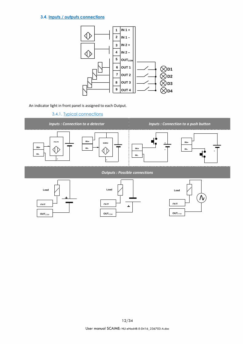
3.4. Inputs / outputs connections
An indicator light in front panel is assigned to each Output.
3.4.1. Typical connections
Inputs : Connection to a detector Inputs : Connection to a push button
Outputs : Possible connections
A5
IN 1 + IN 1 – IN 2 + IN 2 – OUTCOM OUT 1 OUT 2 OUT 3 OUT 4
2
3
4
5
6
7
8
1
9
D1
D2
D3
D4
PNP
+
-
S IN+
IN-
NPN
+
-
S
IN+
IN-
+
-
IN+
IN-
+
-
IN+
IN-
+
-
Load
OUT
OUTCOM
+
-
Load
OUT
OUTCOM
Load
OUT
OUTCOM

13/34
User manual SCAIME: NU-eNod4B-E-0416_236703-A.doc
4 COMMUNICATION
4.1. Communication Interface connections
4.1.1 Process control communication
Version Type of communication Connector
eNod4 DIN
RS485 Automate A7
CAN A6
eNod4 PRO DIN Profibus DP A7
Note: For a better transmission quality on a RS485 or CAN communication network it must be wired to follow
a line topology and must be terminated by an end of line (EOL) impedance at both ends. A 150Ω EOL
impedance is available on eNod4. To use this impedance set the corresponding jumper.
The PROFIBUS communication terminal is electrically isolated from power supply (isolation voltage: 1000V)
In PROFIBUS communication jumper JP5 must be removed. When eNod4 is positioned at the end of the line, use
specific connector DB9 for PROFIBUS with end of line resistor and bias resistors incorporated.
CAN communication is not electrically isolated from power supply. Admitted common voltage on CANBUS is ±27V
from 0V power supply. Depending on installation configuration, the usage of opt couplers or other galvanic isolation
devices is strongly recommended.
Note: If multiple elements connected to the CAN bus are using power supplies with different reference levels
(0V); the problem mentioned above can occur.
The data rate that can be transmitted on different buses depends on the length of the bus. The table below shows
what are the transmission rates supported by eNod4 and the corresponding maximum bus length:

14/34
User manual SCAIME: NU-eNod4B-E-0416_236703-A.doc
CAN bus Profibus bus
data rate max bus length data rate max bus length data rate
1 Mbit/s 25 m 12 Mbit/s 100m -
800 kbit/s 50 m 3 Mbit/s 100m -
500 kbit/s 100 m 1.500 Mbit/s 200m 70m
250 kbit/s 250 m 500 kbit/s 400m 200m
125 kbit/s 500 m 187.5 kbit/s 1000m 600m
50 kbit/s 1000 m(1)
93.75 kbit/s 1200m 1200m
9.6 kbit/s 1200m 1200m
(1) For buses whose length is greater than 5000 m, the use of repeater type systems may be necessary to ensure the
quality of transmissions.
(2) The network speed is set by the PROFIBUS master. eNod4 PRO DIN performs self-adjustment.
(3) Type A cable: AWG 22, impedance: 135 to 165Ω.
(3) Type B cable: AWG 24, impedance 100 to 130Ω.
4.1.2 PC communication
Both models: eNod4 DIN and eNod4 PRO DIN can communicate with a PC using the protocols ModBus RTU or
SCMbus through the USB connector accessible from the front panel.
The appropriate USB driver can be downloaded from our website: http:// www.scaime.com, it is also available on CD
to order from our sales department.
Note: If eNodView software has been correctly installed, it is not necessary to re-install the USB drivers when
connecting another eNod4 on the same USB port (Windows only asks for the driver if the device is connected
to another USB port).
4.1.3 AUX Communication (for HMI)
AUX eNodTouch HMI must be connected through connector AUX(A4). The common mode voltage admitted is ±
27VDC from GND power supply.
When eNod4 is positioned at the end of the line the 150 Ω integrated resistor can be used (connecting jumper).

15/34
User manual SCAIME: NU-eNod4B-E-0416_236703-A.doc
4.2. Communication address selection
Rotary switches selection (SW1 and SW2) accessible from the front panel. The new address only is taken into account after a reset.
4.3. Communication rate selection
Dipswitch selection (SW3) is accessible from the front panel. The new baud rate only is taken into account after a reset.

16/34
User manual SCAIME: NU-eNod4B-E-0416_236703-A.doc
4.4. Protocoles de communication
Version Communication
interface Protocols* Connector
LED on front panel
eNod4 DIN
RS485 PLC ModBus RTU A7 /
RS485 AUX ModBus RTU
SCMBus A8 /
USB ModBus RTU
SCMBus
USB
Front panel USB
CAN CANopen® A6 MS
eNod4 PRO DIN
Profibus Profibus DP-V1 A7 NS
USB ModBus RTU
SCMBus
USB
Front panel USB
* See protocols description in document: eNod4 software user manual.
4.5. Simultaneous functioning of communications
4.5.1 Standard version
PC Connection
AUX Connection
PLC Connection
eNodTouch
Simultaneous communication RS 485 PLC RS485 AUX CAN
USB yes* No yes*
RS 485 PLC yes No
RS485 AUX yes**
(*) Simultaneous use of CAN or RS485 PLC with USB port can reduce performance of this interface.
(**) In this configuration, we recommend a low speed rate on AUX output.

17/34
User manual SCAIME: NU-eNod4B-E-0416_236703-A.doc
4.5.2 Profibus version
PC Connection
AUX Connection
PLC Connection
PROFIBUS-DPV1
eNodTouch
Simultaneous communication Profibus RS485 AUX
USB yes* No
Profibus yes**
(*)Simultaneous use of Profibus with USB port can reduce performance of this interface.
(**) In this configuration, we recommend a low speed rate on AUX output.

18/34
User manual SCAIME: NU-eNod4B-E-0416_236703-A.doc
5 CALIBRATION AND SCALE ADJUSTMENT
eNod4 is factory calibrated to deliver 500 000 counts for 2mV/V with a load cell on the A3 input connector.
Initial calibration can be modified for a better adjustment to the usage or because of characteristics of the sensor. To
achieve these various types of adjustments the following options and procedures are available:
• physical calibration
• theoretical calibration
• scale adjustment coefficient
• gravity correction
5.1. Physical calibration
Physical calibration is done by applying to the sensor from 1 up to 3 known references.
5.2. Theoretical calibration
The theoretical calibration allows defining eNod4 user span without using calibration reference. The information
needed to achieve the procedure is the sensor sensitivity and its rated capacity.
For example a 15kg load cell with sensitivity equal to 1.870 mV/V at 15kg; put sensor maximum capacity 15 000 and
sensor sensitivity 1,870.
5.3. Scale adjustment coefficient
Initial calibration value can be modified with a scale adjustment coefficient. This coefficient has maximum and
minimum values.
5.4. Gravity correction
When eNod4 is used to condition a weighing sensor, it can be necessary to adjust measurement if the place of
measurement is different from the place where eNod4 was calibrated. eNod4 automatically adapts its span by storing
into its non-volatile memory these 2 parameters: ‘Calibration place g value’ and ‘Place of use g value’. Initial values for
these coefficients are identical; they correspond to the g value of a calibration place located in ANNEMASSE FRANCE.
5.5. Scale interval
The scale interval is the difference between 2 consecutives indications. Possible values are: 1, 2, 5, 10, 20, 50, and 100.
Modification of scale interval is taking into account after a new calibration.

19/34
User manual SCAIME: NU-eNod4B-E-0416_236703-A.doc
6 FILTERS
There are four available filtering levels which can be associated:
• Filtering related to the A/D conversion rate including rejection of the mains frequency (50 or 60 Hz)
harmonics.
• Low-pass Bessel filter
• Notch filter
• Moving average filter
6.1. Filtering related to the A/D conversion rate
The signal resolution is related to the conversion rate. The conversion rate might be chosen as low as possible,
particularly for static applications. For dynamic applications, a compromise must be found between the measurement
rate and the low-pass filter cut-off frequency. The eNodView software can be used to determine appropriate filter
values. Choose a measurement rate that rejects the mains frequency harmonics according to the place of use, 50 or
60Hz.
6.2. Bessel low pass filter
A low-pass digital filter can be applied as an output of the A/D converter. The filter orders (available values are 2 or 3)
and cut-off frequency are adjustable. eNodView software can be used to determine appropriate filter values.
6.3. Notch filter
A notch filter might be applied as an output of the low-pass filter (if used) or the A/D converter. It allows attenuating
the frequencies within a band defined by high and low cut-off frequencies. The eNodView software can be used to
determine appropriate filter values.
6.4. Moving average filter
This filter can be set in cascade after the previous filters. The Moving average filter is used to smooth the weight value
in case of random interferences. This sliding average computes the mean of the ‘n’ last measures from the results of
the previous activated filters. A high filter depth gives a better stability, with a longer response time.

20/34
User manual SCAIME: NU-eNod4B-E-0416_236703-A.doc
7 INPUTS FUNCTIONING
Each input can work in positive or negative logic individually. A Debounce time attached to all inputs can be adjusted.
7.1. Inputs assignment:
Function Operating mode
transmitter Belt scale Belt weigh feeder
none
tare
cancel tare
zero
transmit measurement
measurement window
dynamic zero
Start/Stop
Belt running detection
Clear totalization and dosing
error counter
Sensor input control
7.2. General functions
7.2.1 None
Inputs have no effect.
7.2.2 Tare
One or the other or both inputs can be assigned to the tare function. The tare acquisition is conditioned by a stability
criterion that can be changed or inhibited.
Depending on the chosen logic (positive or negative), the tare is triggered by a rising or a falling edge.
7.2.3 Cancel tare
Depending on the chosen logic (positive or negative), the current stored tare value is erased by a rising or a falling
edge.
7.2.4 Zero
One or the other or both inputs can be assigned to the zero function.

21/34
User manual SCAIME: NU-eNod4B-E-0416_236703-A.doc
A new volatile zero value is acquired only if its value is within ±10% range of the specified capacity for a usage out of
legal for trade and ±2% for legal for trade application. The zero acquisition is conditioned by a stability criterion that
can be changed or inhibited.
Depending on the chosen logic (positive or negative), the zero is triggered by a rising or a falling edge.
7.2.5 Transmit measurement
This is only possible using standard or fast SCMBus format or CANopen® protocols.
The request can apply to:
• gross measurement.
• net measurement.
• factory calibrated measurements
A single measurement is transmitted per rising or falling edge (depending on the configured logic) on the input signal.
7.2.6 Measurement window
This is only possible using standard or fast SCMBus.
The request can apply to:
• Gross measurement.
• Net measurement.
• Factory calibrated measurements.
While the input is kept at the right level, a series of measurements are transmitted at the period defined by the
‘sampling period’ setting. Only input 2 is operational if both inputs are assigned to
7.2.7 Sensor input control
The assignment of logical input to sensor input control function allows performing special procedure to diagnose load
cell sensor input. Beforehand, user must acquire reference value of the load cell input by sending 'Sensor input control
reference' specific command (e.g. after the device is calibrated).
Fig. 8
Load
t
input
outputperiod
Measur.
Load
t
input
Measur.
Fig. 7

22/34
User manual SCAIME: NU-eNod4B-E-0416_236703-A.doc
Note: Load cell sensor input control must be realized if no dosing cycle is in progress.
7.3. Functions attached to an operating mode:
See corresponding sections for a complete description.

23/34
User manual SCAIME: NU-eNod4B-E-0416_236703-A.doc
8 OUTPUTS FUNCTIONING
Each output can work individually in its own logic.
8.1. Outputs assignment:
Outputs individually might be assigned to following functions:
function Operating mode
transmitter Belt scale Belt weigh feeder
none
set point
motion
defective measurement
input image
level on request
belt alarms
external totalizer
belt system running
batch in progress
batch result available
conveyor starting alarm
material TOR gate
8.2. General functions:
8.2.1 None:
The output has no function
8.2.2 Set point:
The outputs can be assigned to configurable set points (cf. §8) Output 1 is assigned to set point 1 , output 2 to set
point 2, output 3 to set point 3 and output 4 to set point 4.
Set points are characterized by a high and a low value.
Their operating mode is either operating in hysteresis or operating in window.

24/34
User manual SCAIME: NU-eNod4B-E-0416_236703-A.doc
The low and high values of these set points may be assigned either to (regardless of the operating mode):
gross measurement
net measurement
Sensor input control result
Batch
8.2.3 Motion:
The outputs can be assigned to copying measurements stability.
8.2.4 Defective measurement:
The outputs can be assigned to copying the measurements faults. These faults are also coded in the status word:
Signal outside the converter analog input range
Signal outside the capacity on the positive side
Signal outside the capacity on the negative side
8.2.5 Input image:
Outputs can be assigned to copying inputs state, either using the same logic or inverting the input state (negative
logic). Outputs 1 and 3 are assigned to input 1&3 and outputs 2 and 4 are assigned to input 2&4.
8.2.6 Level on request:
The input level is driven by master requests.
8.3. Functions attached to an operating mode:
See corresponding sections for a complete description.
8.4. Optional analog output (IO+ version)
An optional analog board in current and voltage might be used with eNod4 to provide IO+ version. This has to be
requested when ordering eNod4 product.
Voltage output might be set either 0/5V or 0/10V, and the current output to 4/20mA, 0/24mA, 0/20mA or 4/20mA
with alarm at 3.6mA. Both output (current and voltage) might separately be enable.
Analog output assignment function is common to both current and voltage output and might be assigned to
followings:

25/34
User manual SCAIME: NU-eNod4B-E-0416_236703-A.doc
function Operating mode
transmitter Belt scale Belt weigh feeder
none
gross mesasurement
net mesasurement
level on request
flow rate control output
instant flow rate
average flow rate
average belt speed
If extraction command is directly done by an external device (e.g PLC), through eNod4 analog output, the output must
be set on level on request function.

26/34
User manual SCAIME: NU-eNod4B-E-0416_236703-A.doc
9 BELT WEIGHER OPERATING MODE
9.1. Introduction and Overview
eNod4 belt conveyor scale is a device that continuously measures bulk material as it moves along a conveyor. The
system requires two general parameters to operate:
• It needs to know the weight of the material being moved along the conveyor belt
• It needs to know the speed at which it’s moving along the conveyor belt.
The weight of the material on the belt is determined by weighing a section of conveyor belt loaded with material and
then subtracting the average weight of the unloaded belt. The speed at which the material is moving is determined by
measuring the speed of an idler or wheel in contact with the conveyor belt. The weight and speed is combined to
produce a running total and a rate of flow of material going through the belt conveyor scale. The correct operation of
the scale system requires the components to be installed correctly, periodically calibrated, and properly maintained.
Belt scale operation
In belt scale operating mode, eNod4 continuously calculates the total amount of material that goes through the
weighing system and calculates the flow rate of material instantaneously.

27/34
User manual SCAIME: NU-eNod4B-E-0416_236703-A.doc
Belt weigh feeder operation
The weigh feeder is used to deliver an accurate mass flow rate of materials. In most applications, materials are
provided by an adjustable mechanical shear gate, which fixes the correct material bed depth for a given particle size.
The feed rate is then maintained adjusting the speed of the belt. However, in some cases the belt speed is constant
with rate control done by a pre-feeding device.
The system consists of three components: weight and speed sensing, integration and control, and the mechanical
conveying system.
Using the belt load and the belt speed signals, small incremental totals of weight per time are measured by eNod4
which calculates the flow rate. The measured flowrate is compared to the set point flow rate and the on-board PID
controller makes necessary corrections to the belt speed or materials feed.
9.2. Totalization cycle description
9.2.1 Cycle options
Cycle options define eNod4 device functioning
• Batch mode
If batch mode option is activated, eNod4 will automatically stop dosing when the total weight will have reached batch
target values (Batch set point minus Inflight weight value), the scale material flow stops automatically.
The batch target value consists of two variables, the main weight to totalize in weight unit x 1000 and the
complementary weight to totalize in weight unit.
Inflight weight value is expressed only in weight unit.
28/34
User manual SCAIME: NU-eNod4B-E-0416_236703-A.doc
• Clear totalization
If cleared totalization at starting of new cycle option is activated, eNod4 reinitializes total value. The main variable
weight to totalize in weight unit x 1000 and the complementary weight to totalize in weight unit are reset to zero.
• PID Activation
It is possible to assign eNod4 current or voltage analog output to extraction command (Setting to flow rate control
output).
In weight feeder mode, when PID activation option is activated, eNod4 will adjust the flow of extraction function to
maintain constant flowrate regarding the flowrate set point. The measured flowrate is compared to the set point flow
rate and the on-board PID controller makes necessary corrections to the belt speed or materials feed.
The configuration of this plan of regulation can be made in a totally automatic way.
So that this plan of regulation works, it is necessary to realize weight calibration indication and flow rate calibration
beforehand.
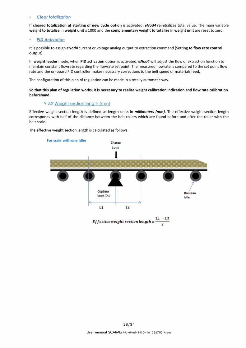
9.2.2 Weight section length (mm)
Effective weight section length is defined as length units in millimeters (mm). The effective weight section length
corresponds with half of the distance between the belt rollers which are found before and after the roller with the
belt scale.
The effective weight section length is calculated as follows:

29/34
User manual SCAIME: NU-eNod4B-E-0416_236703-A.doc
9.2.3 Conveyor inclination (degrees)
“Belt tilt angle” (angle of conveyor in degrees) allows correcting the effect of inclination on the weight. If the belt is
mounted horizontally, the definition is 0. The belt can be tilted to a maximum of 35°.
Always ensure that the definition corresponds with the current tilt angle, otherwise the belt load is incorrectly
calculated.
9.2.4 Minimum load to totalize (weight unit/meter)
Minimum load to totalize is the limit value for minimum belt loading in 0.01 % of totalization weight unit. The entry of
the number e.g. 1000 corresponds to 10 weight unit. After this value has been exceeded eNod4 sets the status bit
“min. totalize load targeted” in status register and starts totalization function.
eNod4 determines the Minimum load to totalize by calculating:
9.2.5 Pulses factor speed sensor (Pulses/meter)
The pulse constant of the speed sensor indicates the number of pulses per meter of the belt. eNod4 calculates the
current belt speed on this base. The value of pulses factor can be calculated by eNod4 during a speed calibration.
9.2.6 Measurement time factor for speed (x250ms)
The belt speed is defined as output in meter per second (m/s). By default eNod4 device estimated speed
determination every 250ms (time factor for speed is set to 1). The measuring time factor of the pulse input can be set
to another time e.g. 4 (for 2 seconds). The number of pulses from the speed sensor within this period is summed to

30/34
User manual SCAIME: NU-eNod4B-E-0416_236703-A.doc
estimate the belt speed. The speed value output is updated in this case every 2 seconds and the value is shown in
eNod4 as meter per second.
9.2.7 Constant belt speed (m/s)
Constant belt speed must be defined if no speed sensor is connected to eNod4 device. The calculation of the flow-rate
is then performed using this value.
When a speed sensor is connected to eNod4, constant belt speed must be set to 0.
9.2.8 Flow correction factor
Correction factor can be used to correct deviations in the total dosed amount by compensating for mechanical
variations. When the final dosed amount is checked by weighing the resulting weight, eNod4 can recalculate this
factor by calculating:
The next batch the Batch Total and Checked Batch Total should be close together.
9.3. Belt calibration
Initial calibrations must be performed on belt system to achieve correct display of process data. User has to do the
following steps:
1) Speed sensor calibration (mandatory)
2) Static weight calibration (mandatory)
3) Material Test (Dynamic weight calibration or correction factor)
9.3.1 Speed sensor calibration
Speed calibration must be performed when the conveyor is running and empty. The following parameters are involved
during speed calibration procedure:
• Pulses factor speed sensor (Pulses/meter), user can get this data from speed sensor datasheet. Using this
parameter, eNod4 allows estimating the conveyor total length.
• Conveyor total length, if user does not know pulses factor speed sensor (pulses/meter), he has to fill this
parameter and eNod4 allows estimating pulses factor. At end of calibration the current belt speed must
match the real speed.
• Number of revolutions, for auto-calculation of pulses factor or conveyor total length, user must fill this
parameter with correct value (effective number of revolutions to be realized during procedure). It is
recommended to set and to achieve a maximum number of revolutions to improve result accuracy.
Procedure of auto-calculation (pulses factor or total length) is as following:
• Stop the conveyor and make sure it is empty
• Mark the belt (for reference point)
• Start the conveyor
• Send corresponding “Init calibration” command at marked point
• Count real number of belt revolutions handled
• Send corresponding “End calibration” command at marked point and when specified number of
revolutions is done.
• Check and compare updated value of pulses factor or conveyor total length.
Note: See functional commands section about commands list.
9.3.2 Static weight calibration
Static weight calibration must be performed when the conveyor is in stop state. eNod4 device allows several methods
of static weight calibration. These methods and procedures are described in specific calibration and scale adjustment
section. Refer to it for more details.

31/34
User manual SCAIME: NU-eNod4B-E-0416_236703-A.doc
9.3.3 Material Test (Dynamic weight calibration or correction factor)
The Material Test can only be performed once a static weight calibration has been completed and once the belt speed
sensor has been installed and calibrated.
The belt scale allows for two calibration methods. Static weight calibration is the easiest method and is a combination
of test weights applied to each weigh idler, belt spacing and speed calibration. The second optional calibration
method is a Material Test calibration in which a known amount of test material is fed on the moving belt scale. Then,
user must check the amount of test material with a measurement instrument and apply a correction factor to make at
next batch eNod4 displayed total weight matches the test material weight.
9.4. Calibration of flow rate
So that eNod4 can carry out an expected flow rate dosing in the best conditions possible, the flow rate output control
calibration is required. This also applies when eNod4 is used both as belt scale or belt weigh feeder.
From this calibration will depend the accuracy of the flow rate obtained and on the actuation time delay, if a PID
regulator controls it. This calibration is carried out in minimum two segments by the variable segments number for
the calibration curve of flow rate. In case the extraction device has a nonlinear response it is recommended to define
maximum segments for the flow rate calibration.
If the control of extraction device is directly provided by eNod4 through a control analog output in current or voltage,
the current or voltage analog output of eNod4 must be allocated to “level on request” function.
For each calibration point of the variable control output value, read the appropriate average flow rate. Then provide
each of the Calibration of control output point n / analog output and Calibration of flow rate point n matching with
control output value. Validate the flow rate calibration by calibration of flow rate control.
Allocate in the end the current or voltage analog output of eNod4 to “flow rate control output” function.
9.5. Totalization
eNod4 realizes totalization function continuously while belt loading is greater than minimum load to totalize even if
no batch cycle is in progress.
The totalization result is composed of two parts, the main part in weight unit x 1000 and the second one
complementary in weight unit.
In batch mode and when cleared totalization at starting new cycle option is activated, this totalization result is set to
zero at each cycle start.
There are two others levels of totalization expressed only in weight unit x 1000 (Great total and General total).
Each totalization result can be independently set to zero. The data of these totalizers is being permanently backed up
after modification.
If one of these 4 outputs is allocated to an external totalizer, a pulse is sent when the value totalized increases by a
multiple value of the parameter weight quantity per pulse on logical output.
9.6. Alarms
Alarms are disabled when the corresponding control parameters are set to zero, otherwise they are activated. These
alarms will not affect the functioning of eNod4 device but only be displayed. They will continue to be displayed until
the condition disappears. Once the condition is cleared, the alarm is cleared.
The following data process can be monitored:
• Instant flowrate
• Instant belt load
• Flowrate control output
• Instant belt speed
• External totalizer overflow
9.6.1 Minimum flow rate limit value (0.1%)
Minimum flow rate is the limit value for flowrates in 0.1% of the nominal flowrate. The entry of the number e.g. 800
corresponds to 80.0%. When the instant flowrate on the belt is lower than this level, eNod4 sets the alarms bit “<min.
instant flowrate” in belt alarms register.

32/34
User manual SCAIME: NU-eNod4B-E-0416_236703-A.doc
9.6.2 Maximum flow rate limit value (0.1%)
Maximum flowrate is the limit value for flowrates in 0.1% of the nominal flowrate. The entry of the number e.g. 1020
corresponds to 102.0%. When the instant flowrate on the belt is higher than this level, eNod4 sets the alarms bit
“>max. instant flowrate” in belt alarms register.
9.6.3 Minimum belt load limit value (0.1%)
Minimum belt load is the limit value for density weight in 0.1% of the nominal load. The entry of the number e.g. 800
corresponds to 80.0%. When the instant density weight on the belt is lower than this level, eNod4 sets the alarms bit
“<min. instant load” in belt alarms register.
9.6.4 Maximum belt load limit value (0.1%)
Maximum belt load is the limit value for density weight in 0.1% of the nominal load. The entry of the number e.g.
1020 corresponds to 102.0%. When the instant density weight on the belt is higher than this level, eNod4 sets the
alarms bit “>max. Instant load” in belt alarms register.
9.6.5 Minimum control output limit value (0.1%)
Minimum control output is the limit value for control output in 0.1% at nominal flowrate. The entry of the number
e.g. 800 corresponds to 80.0%. When the control output on the belt is lower than this level, eNod4 sets the alarms bit
“<min. control output” in belt alarms register.
9.6.6 Maximum control output limit value (0.1%)
Maximum control output is the limit value for control output in 0.1% at nominal flowrate. The entry of the number
e.g. 1020 corresponds to 102.0%. When the control output on the belt is higher than this level, eNod4 sets the alarms
bit “>max. control output” in belt alarms register.

33/34
User manual SCAIME: NU-eNod4B-E-0416_236703-A.doc
9.6.7 Minimum belt speed limit value (0.1%)
Minimum belt speed is the limit value for minimum belt speed in 0.1% of the nominal speed. The entry of the number
e.g. 800 corresponds to 80.0 %. After this value has been exceeded, eNod4 sets the status bit “<min. speed” in belt
alarms register.
9.6.8 Maximum belt speed limit value (0.1%)
Maximum belt speed is the limit value for maximum belt speed in 0.1% of the nominal speed. The entry of the number
e.g. 1020 corresponds to 102.0%. After this value has been exceeded, eNod4 sets the status bit “>max. speed” in belt
alarms register.
9.6.9 Inhibit time of speed alarms at start (ms)
Monitoring the belt speed is only activated after this delay time when the belt is started.
9.6.10 Inhibit time of speed alarms in service (ms)
When the belt speed is below/above the min/max belt speed, the alarm is activated after this delay elapsed.
9.6.11 Errors counter
Any alarm disappears automatically when the origin of the defect disappears. In every emitted alarm, the variable
error counter is incremented.
Error counter variable can only be set to zero using clear dosing/batch command.

34/34
User manual SCAIME: NU-eNod4B-E-0416_236703-A.doc
9.7. Inputs assignments
eNod4 device could have up to 5 Inputs (with IO+ option). One of them is especially reserved for speed sensor input.
All others logical inputs can be assigned to functional dosing process commands. All process commands have edge
functioning.
• Start / Stop dosing (and batch)
If starting conditions are fulfilled, a rising or a falling edge (according to the configured logic) on this input causes a
new totalization cycle to start.
In batch mode and when cleared totalization at starting new cycle option is enabled, the totalization result is set to
zero at each cycle start.
If dosing cycle is running, a second edge of this command stops the process.
• Belt running motion detection
If speed sensor is broken or if no speed sensor is connected to eNod4 device, a logical input on the eNod4 can be
assigned to motion detection function to enable totalization function.
• Clear/Reset totalization and errors counter
Clear totalization function can be assigned to logical input. You can clear total amount dosed and errors counter at
any time. At this input activation on rising or falling edge (according to the configured logic), the main total in weight
unit x1000 and the complementary weight value are reset to zero.
Also, errors counter parameter is set to zero.
• Dynamic zero
When the belt is running empty, this input activation will cause eNod4 to perform conveyor zero function by
measuring flow rate of materials.
Run the conveyor for several minutes to ensure the belt is empty and supple. The conveyor should be operating at
normal speed throughout the calibration. Dynamic zero function duration will depend on the number of revolutions
chosen, the belt length and the speed. The procedure will complete its cycles unless an exit calibration command is
sent.