digital ic tester - edge.rit.eduedge.rit.edu/edge/p17342/public/detailed design...
TRANSCRIPT
DigitalICTester
1
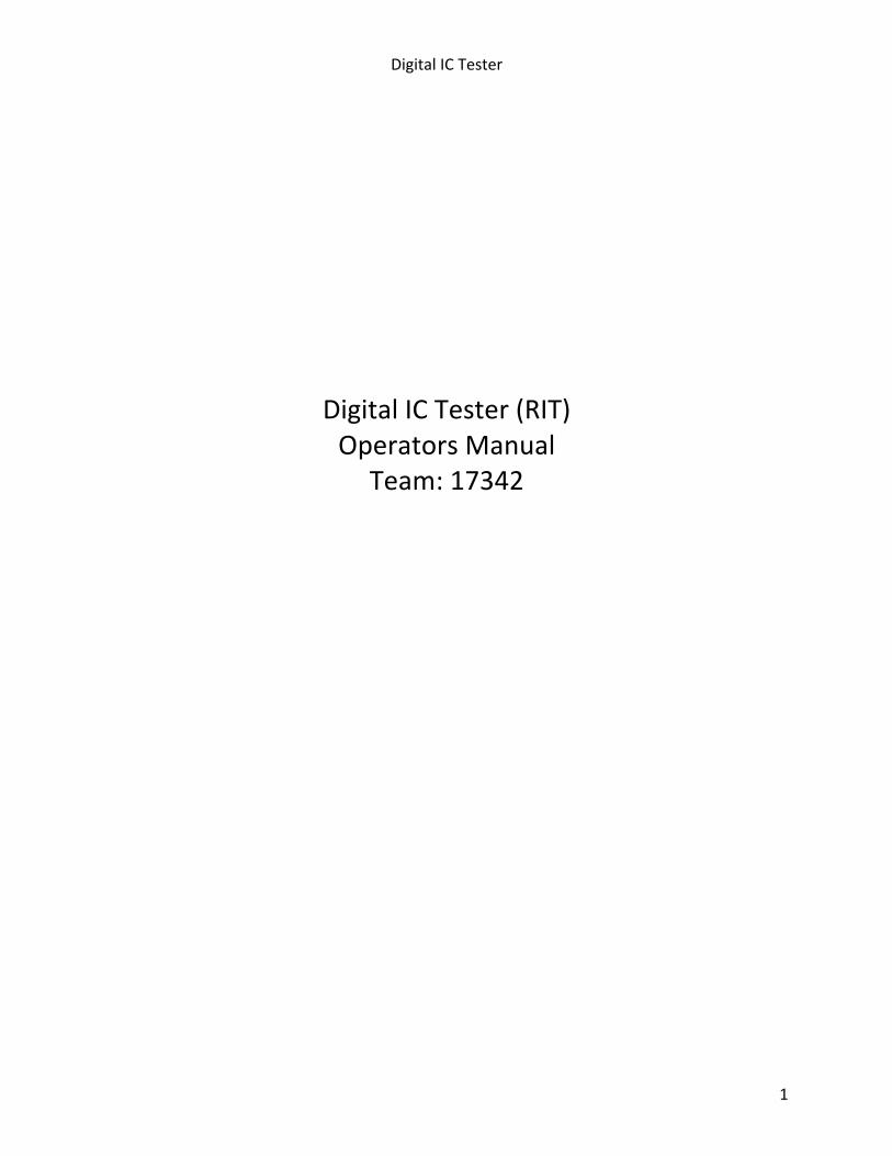
DigitalICTester(RIT)OperatorsManual
Team:17342
DigitalICTester
2
CONTENTS
1. Introduction 3
2. PowerSupply 3
3. SwitchingOn 5
4. OperatingModes(executetests,sleepmode) 5
5. SelectTest 5
6. TestIC 7
7. TestResults 7
8. AddNewTests 8
9. Specifications 9
DigitalICTester
3
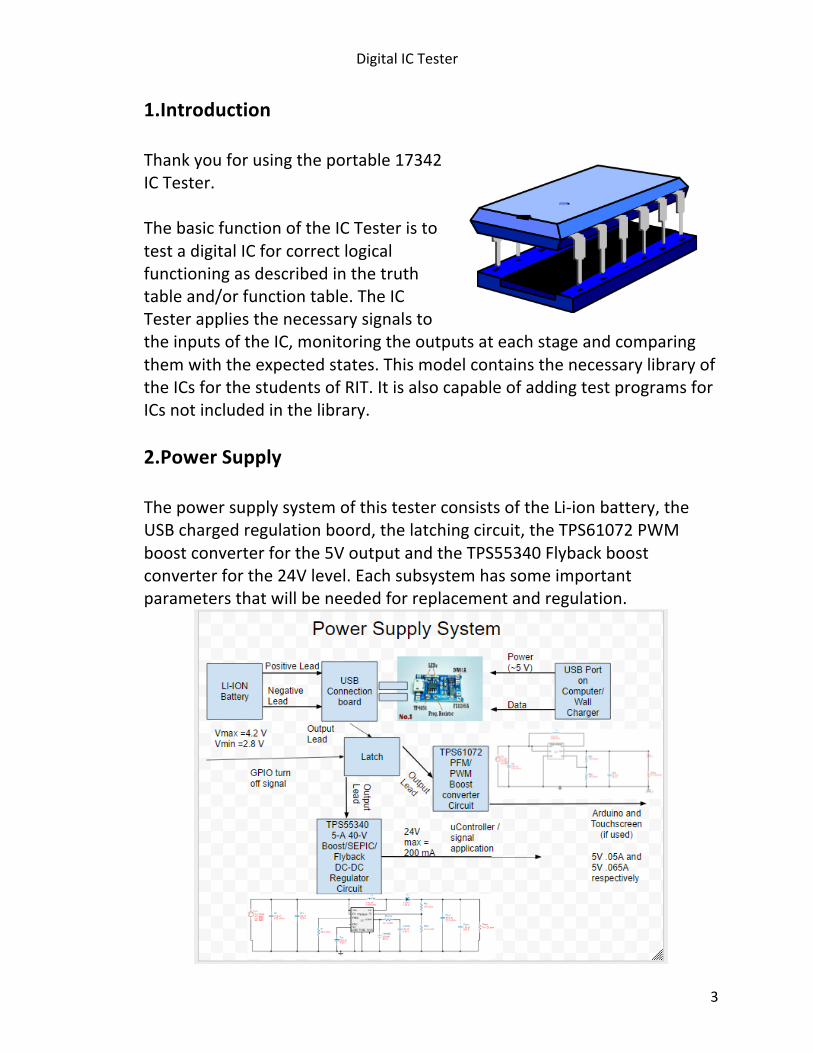
1.Introduction
Thankyouforusingtheportable17342ICTester.ThebasicfunctionoftheICTesteristotestadigitalICforcorrectlogicalfunctioningasdescribedinthetruthtableand/orfunctiontable.TheICTesterappliesthenecessarysignalstotheinputsoftheIC,monitoringtheoutputsateachstageandcomparingthemwiththeexpectedstates.ThismodelcontainsthenecessarylibraryoftheICsforthestudentsofRIT.ItisalsocapableofaddingtestprogramsforICsnotincludedinthelibrary.2.PowerSupply
ThepowersupplysystemofthistesterconsistsoftheLi-ionbattery,theUSBchargedregulationboord,thelatchingcircuit,theTPS61072PWMboostconverterforthe5VoutputandtheTPS55340Flybackboostconverterforthe24Vlevel.Eachsubsystemhassomeimportantparametersthatwillbeneededforreplacementandregulation.
DigitalICTester
4
Li-ionRechargeableBattery:
• BatteryistheSamsungICR18650-26Hcell.• Specssheetlinkis:
http://www.tme.eu/en/Document/e06617d885c58dfb3fecaf4abbe330c4/ICR18650-26H.pdf
• OfficialSpecsandDischargeCurves:http://www.candlepowerforums.com/vb/showthread.php?389665-Samsung-ICR18650-26H-2600mAh-(Pink)
• IfanewBatteryischosen,itneedstobecompatiblew/USBboard TP4056-MicroUSB5V1ALithiumBatteryChargerboard:
• Fullchargevoltageis4.2V,at1Achargingcurrent,LEDwillchangetobluewhencharged.
• http://www.haoyuelectronics.com/Attachment/TP4056-modules/TP4056.pdf
• Chargestypical3.7VnominalLiPocells,hasvoltageprotection• NotpurchasablebytypicalMSDsources:Amazon,HAOYUelectronics
TPS61072PWMBoostConverter • Inductorrampuptakes~2.3stogettowardsoutputtofinal5Vvalue
fromthevaryingsupplyof4.2Vtominimum~2.8V.• TechnicalSheetishere:
http://www.ti.com/lit/ds/symlink/tps61072.pdf TPS55340FlybackBoostConverter
• Inductorrampuptakesalmost3sbeforetheoutputapproachesthe24Vlevelandsettlesoffnear6ms
• TechnicalSheetishere:http://www.ti.com/general/docs/lit/getliterature.tsp?genericPartNumber=tps55340&fileType=pdf
• 24Vlevelisformeasurementcircuits5VrunstheArduinoandTouchscreenortheLCD.
OtherImportantnotes: • Both24Vlevelandbatteryarecomparedtothe5Vlevel,when
batterylevelislessthan20%or3.125Vthecontrollerwillhaveanalertforlowbatterylevelislow:chargethebattery.
• USBboardischargedviaregularcomputeroroutletwithadapter• Pleasebecarefulwithlivewires.
DigitalICTester
5
• Battery:Ifnecessary,batterymayberemovedandreplaced.Asitislithiumionrechargablethisshouldbeifanemergencyoccurs.Powereverythingoffentirely.Thebatterywillbeinaseparateportionfromthepcb,removetheobjectsarounditandthescrewsorcasing.Inordertoremove,solderingironmustbeusedontheregulationboardcarefullyinordertonotdamagethetester.Eithertheleadsmustbede-solderedcorrectlywithasoldersuckerorresin,andthebatterymovedaway.Theusermaycuttheleadsandreplacethemandthebattery.Eitherthatortherubberoutsidemustbecarefullyremovedandbatterydisconnected.Ifthebatteryisreplaced,theleadsshouldbeconnectedandthebatteryshouldbewrappedasitwasbeforeandsolderedorconnectedbackoncarefully.
3.SwitchingOn
Toswitchtheuniton,simplypressthepowerbutton.Topreservebatterylife,theunitpowersitselfoffafterapproximately30secondsofnonuse.Toshutoffthetesterpressthepowerbuttonfor~3s. Onthetouchscreenthereisanoptiontopressforpoweringoffaswell. Inthesettingselectiononthetouchscreenthereisanoptionforthetimeoutofthethedeviceallowingthe30sautopowerofftobeincreasedordecreasedinincrementsof5s.Afterthetimeoutisadjustedupto1minute,thetimeoutincrementsby15sintervalsupto~5minutes.
4.OperatingModes
TheICtesterhasanumberoftestmodesthatareselectedfromthemainscreen.TheTouchScreenhasasleepmodeitselfwhichdrawslesscurrent.Thetesterwillhaveaperiodafterthetestselectionofexecutingthetests.
5.SelectTest
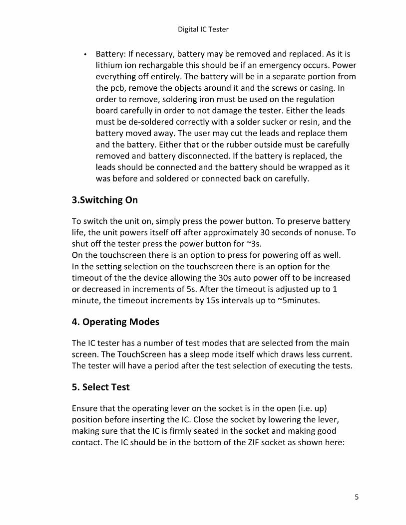
Ensurethattheoperatingleveronthesocketisintheopen(i.e.up)positionbeforeinsertingtheIC.Closethesocketbyloweringthelever,makingsurethattheICisfirmlyseatedinthesocketandmakinggoodcontact.TheICshouldbeinthebottomoftheZIFsocketasshownhere:
DigitalICTester
6
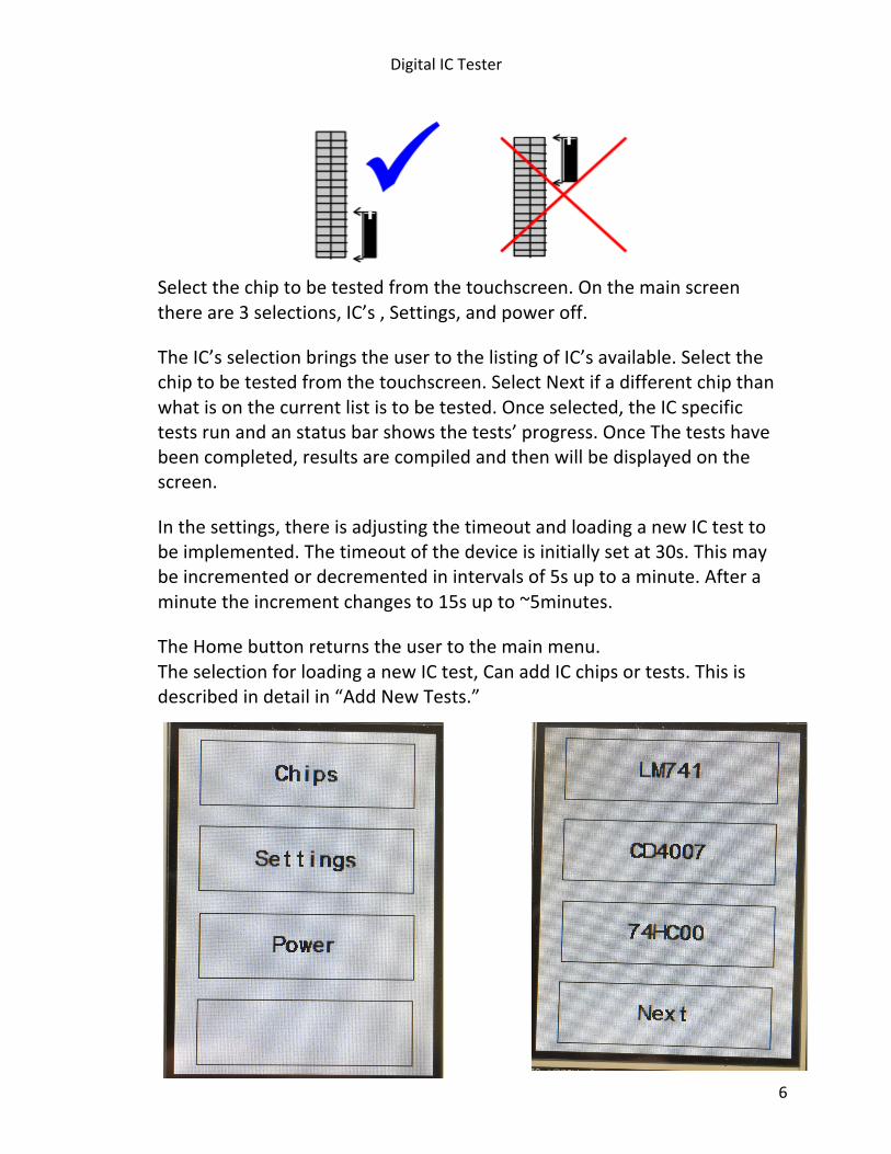
Selectthechiptobetestedfromthetouchscreen.Onthemainscreenthereare3selections,IC’s,Settings,andpoweroff.
TheIC’sselectionbringstheusertothelistingofIC’savailable.Selectthechiptobetestedfromthetouchscreen.SelectNextifadifferentchipthanwhatisonthecurrentlististobetested.Onceselected,theICspecifictestsrunandanstatusbarshowsthetests’progress.OnceThetestshavebeencompleted,resultsarecompiledandthenwillbedisplayedonthescreen.
Inthesettings,thereisadjustingthetimeoutandloadinganewICtesttobeimplemented.Thetimeoutofthedeviceisinitiallysetat30s.Thismaybeincrementedordecrementedinintervalsof5suptoaminute.Afteraminutetheincrementchangesto15supto~5minutes.
TheHomebuttonreturnstheusertothemainmenu. TheselectionforloadinganewICtest,CanaddICchipsortests.Thisisdescribedindetailin“AddNewTests.”
DigitalICTester
7
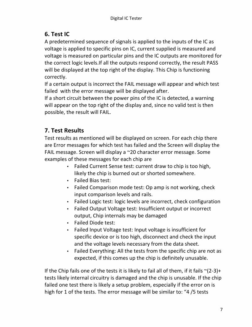
6.TestIC ApredeterminedsequenceofsignalsisappliedtotheinputsoftheICasvoltageisappliedtospecificpinsonIC,currentsuppliedismeasuredandvoltageismeasuredonparticularpinsandtheICoutputsaremonitoredforthecorrectlogiclevels.Ifalltheoutputsrespondcorrectly,theresultPASSwillbedisplayedatthetoprightofthedisplay.ThisChipisfunctioningcorrectly. IfacertainoutputisincorrecttheFAILmessagewillappearandwhichtestfailedwiththeerrormessagewillbedisplayedafter. IfashortcircuitbetweenthepowerpinsoftheICisdetected,awarningwillappearonthetoprightofthedisplayand,sincenovalidtestisthenpossible,theresultwillFAIL.
7.TestResults Testresultsasmentionedwillbedisplayedonscreen.ForeachchipthereareErrormessagesforwhichtesthasfailedandtheScreenwilldisplaytheFAILmessage.Screenwilldisplaya~20charactererrormessage.Someexamplesofthesemessagesforeachchipare
• FailedCurrentSensetest:currentdrawtochipistoohigh,likelythechipisburnedoutorshortedsomewhere.
• FailedBiastest:• FailedComparisonmodetest:Opampisnotworking,check
inputcomparisonlevelsandrails.• FailedLogictest:logiclevelsareincorrect,checkconfiguration• FailedOutputVoltagetest:Insufficientoutputorincorrect
output,Chipinternalsmaybedamaged• FailedDiodetest:• FailedInputVoltagetest:Inputvoltageisinsufficientfor
specificdeviceoristoohigh,disconnectandchecktheinputandthevoltagelevelsnecessaryfromthedatasheet.
• FailedEverything:Allthetestsfromthespecificchiparenotasexpected,ifthiscomesupthechipisdefinitelyunusable.
IftheChipfailsoneofthetestsitislikelytofailallofthem,ifitfails~(2-3)+testslikelyinternalcircuitryisdamagedandthechipisunusable.Ifthechipfailedonetestthereislikelyasetupproblem,especiallyiftheerroronishighfor1ofthetests.Theerrormessagewillbesimilarto:“4/5tests
DigitalICTester
8
passed,the5thtestfailedwith65%errormargin.”Ifso,thechipshouldbereconfiguredandtestedagaintoensuretheparticularerror.Iftheerrordisplays“failedeverything”chipiscertainlyunusable.Ifthechippassesthetests,thechipisnottheissue,thestudent/TAshouldchecktheperipheralcircuitryorthelabsetup. Theusermaychangetheerrormessageintheconfigfileifhe/shesodesiresandaddmessageswithnewspecifictests.
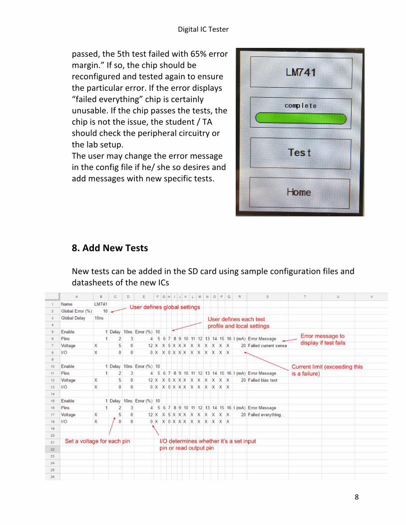
8.AddNewTestsNewtestscanbeaddedintheSDcardusingsampleconfigurationfilesanddatasheetsofthenewICs
DigitalICTester
9
9.Specifications
LM741Datasheet: http://www.ti.com/lit/ds/symlink/lm741.pdf 74HC00Datasheet: https://www.fairchildsemi.com/datasheets/MM/MM74HC00.pdf CD4007Datasheet: http://pdf1.alldatasheet.com/datasheet-pdf/view/50835/FAIRCHILD/CD4007.html
Batteries SamsungICR18650-26Hcell.
DCinput 2.8-4.2V,5Vtousb,1Aboardcurrentmax, regulatedviaTP4056.max
Powerconsumption Poweroff max Standby mA Testing ICdependent Testthresholds(internallibrary)
Testthresholds(userlibrary) 0Vto24V settingsbaud,databits,1stopbit,noparity
DimensionsmmXmmXmmapprox. CaseDimensionsmmXmmXmmapprox.
LibraryICs: CD4007,74HC00,LM741
DigitalICTester
10