digilent pmod™ interface specification 1.1.0 1 … · prior to the digilent pmod interface...
TRANSCRIPT

1300 Henley Court Pullman, WA 99163
509.334.6306 www.store. digilent.com
Digilent Pmod™ Interface Specification 1.1.0
Revised July 28, 2017
Copyright Digilent, Inc. All rights reserved. Other product and company names mentioned may be trademarks of their respective owners. Page 1 of 11
1 Introduction
The Digilent Pmod interface is used to connect low frequency, low I/O pin count peripheral modules to host
controller boards. There are six-pin and twelve-pin versions of the interface defined, encompassing SPI, I²C, UART,
I2S, H-bridge and GPIO protocols. The six-pin version provides four digital I/O signal pins, one power pin and one
ground pin. The twelve-pin version provides eight I/O signal pins, two power pins and two ground pins. The signals
of the twelve-pin version are arranged so that it provides two of the six-pin interfaces stacked.
In general, Pmod modules can plug directly into connectors on the host controller board, called host ports, or be
connected to the controller board via six-pin or twelve-pin cables. Two six-pin peripheral modules can be
connected to a single twelve-pin host port via a twelve-pin to dual six-pin splitter cable. Similarly, a single twelve-
pin peripheral module can be connected to two six-pin host ports via the same twelve-pin to dual six-pin splitter
cable.
Pmod modules are powered by the host via the interface’s power and ground pins.
The Pmod interface is not intended for high frequency operation, however, using RJ45 connectors and twisted pair
Ethernet cable, signals have been sent reliably at 24 MHz and distances of up to 4 meters. Theoretically, signal
speeds greater than 100 MHz should be achievable using high-speed ports with direct connection of Pmod
modules (without the use of cables).
2 Electrical Specifications
The digital signal characteristics are not specified. However, the general expectation is that a 3.3 V logic power
supply will be used and the signals will conform to LVCMOS 3.3 V or LVTTL 3.3 V logic conventions.
The driver current source/sink capability isn’t specified and depends on the capabilities of the specific system
board or module. The I/O pins on the system board are generally directly driven by the FPGA or microcontroller.
The drive strength for FPGA pins is generally in the range +/-16 mA to +/-24 mA. The drive capability of
microcontrollers is generally less and some of them are not symmetrical. The drive strength for microcontroller
pins is generally in the range +/-5 mA to +/-10 mA.
The I/O pins on standard system board Pmod ports generally have ESD protection diodes and 200-ohm series
resistors. The resistors are to limit short circuit currents if pins are inadvertently shorted, or to protect against
driver conflicts if outputs are inadvertently connected together. High-speed Pmod ports are present on some
Digilent system boards and do not have ESD protection diodes or series resistors.

Digilent Pmod™ Interface Specification 1.1.0
Copyright Digilent, Inc. All rights reserved. Other product and company names mentioned may be trademarks of their respective owners. Page 2 of 11
Peripheral modules may be connected to the host via cables of up to 18” in length. The drivers on the host or
peripheral module should have sufficient drive strength to drive this length of cable at whatever the operating
speed of the interface on the Pmod is expected to be. In general, this means that the driver should be able to
source or sink at least 5 mA of current.
With the exception of I2C connected modules, peripheral modules may not assume that pull-up or pull-down
resistors are present on the host and must provide for proper termination of inputs, if necessary, and may not use
open drain or open collector outputs, unless the pull-up is provided on the peripheral module itself.
For all I2C connected modules, the digital signal characteristics conform to the I2C specification. Either 5 V or 3.3 V
levels can be used on most modules, but Digilent system boards operate at 3.3 V, and the modules are primarily
intended for operation at 3.3 V.
Prior to the Digilent Pmod Interface Specification 1.1.0, I2C modules were not required to have onboard pull-ups.
Therefore, it is suggested to include jumpered pull-ups on system boards to be backward compatible with old I2C
Pmods. However, all Pmods designed to conform to specification version 1.1.0 and higher will include onboard
pull-ups that can be jumpered in and out.
3 Power Supply
The power pins of the interface provide power from the host to the peripheral. The complete interface requires
that the host provide the ability to switch the voltage on the power pins between 5.0 V and 3.3 V. A reduced
functionality subset of the specification allows the host to provide only 3.3 V at the power supply pins, with no
ability to switch. On the twelve-pin version of the interface, both power supply pins switch together and always
supply the same voltage. These pins may be shorted together at either the host end or the peripheral end.
On I2C connected modules, the power pin of the interface provides power from the system board to the peripheral
module. The supplied voltage will generally be 3.3 V, but operation at 5 V is supported by some modules. Daisy
chaining six-pin I2C connected modules is possible via the female connector on the board edge opposite the male
connector.
The amount of power a peripheral module is allowed to draw from the host is not specified, but should not be
assumed to be more than approximately 100 mA.
4 Physical Connection Standard
Pmod connections are made using standard 100 mil spaced, 25 mil square, pin-header style connectors.
The peripheral module board will have a male connector. This will typically be a right-angle connector, at the board
edge, for direct connection to a host board. Some older I²C modules have a straight male connector inboard from
the board edge as only cable connections were intended to be used. Beginning with Pmod Specification 1.1.0, all
connectors intended for primary connection to a host board should be right angle male connectors.
Six-pin I²C modules will have a six-pin female connector, centered on the board edge opposite the male connector.
This will typically be a right-angle connector at the board edge and is intended to be used in daisy chaining.
The host board will typically have a 12-pin right angle female connector at the board edge for direct connection of
peripheral module boards, however a straight female connector inboard from the board edge is also allowed.

Digilent Pmod™ Interface Specification 1.1.0
Copyright Digilent, Inc. All rights reserved. Other product and company names mentioned may be trademarks of their respective owners. Page 3 of 11
When multiple Pmod host ports are placed side-by-side along a host board edge, they are spaced 0.9” center-to-
center. This allows for 0.8” wide modules to be plugged side-by-side into a host without mechanical interference.
Peripheral modules with multiple male connectors must also have them spaced on 0.9” centers for direct
connection to a host.
Peripheral modules with a single connector that are intended for direct connection to a host, or that are intended
to fit into the Pmod mounting clip, should be 0.8” wide. There should also be >25 mil of clearance from the board
edge to any components to allow clearance for the Pmod clip to latch the board edge. The connector should be
centered along the 0.8” side of the module.
Peripheral modules that are more than 0.8” wide can be directly connected to a host in most cases but may
interfere with adjacent host ports.
The following diagrams show physical connector placement and pin numbering conventions for the host (system
board) and peripheral module sides of the connection. Note that the pin numbering conventions for the 2x6
connectors are non-standard and are mirrored between the host connector and the peripheral board connector.
Figure 1. Standard 6-pin male connector placement on Pmod boards.

Digilent Pmod™ Interface Specification 1.1.0
Copyright Digilent, Inc. All rights reserved. Other product and company names mentioned may be trademarks of their respective owners. Page 4 of 11
Figure 2. Standard 12-pin male connector placement on Pmod boards.
Figure 3. Standard 6-pin female connector placement on Pmod boards.

Digilent Pmod™ Interface Specification 1.1.0
Copyright Digilent, Inc. All rights reserved. Other product and company names mentioned may be trademarks of their respective owners. Page 5 of 11
Figure 4. Standard 12-pin female connector placement on Pmod boards.
Figure 5. Standard 12-pin female host port placement on host boards.
Digilent Pmod™ Interface Specification 1.1.0
Copyright Digilent, Inc. All rights reserved. Other product and company names mentioned may be trademarks of their respective owners. Page 6 of 11
The connection standard for system boards that provide I²C connectors is to use the standard 12-pin right angle
female connector at the board edge for direct connection of peripheral module boards. The connector provides
two sets of the I2C signals, power and ground, so that the I2C bus can be formed by daisy chaining system boards or
Pmods. The system board can either be the root of one or two daisy chains, or in the middle of a daisy chain.
5 I/O Signal Assignment Conventions
The following define signal assignments to the I/O pins on the connector for certain standard interfaces. In the
following, the direction is defined from the perspective of the host: i.e., ‘Out’ means from the host to the
peripheral; ‘In’ means from the peripheral to the host. Generally, the host is a Digilent system board. The
peripheral will generally be a Digilent Pmod board.
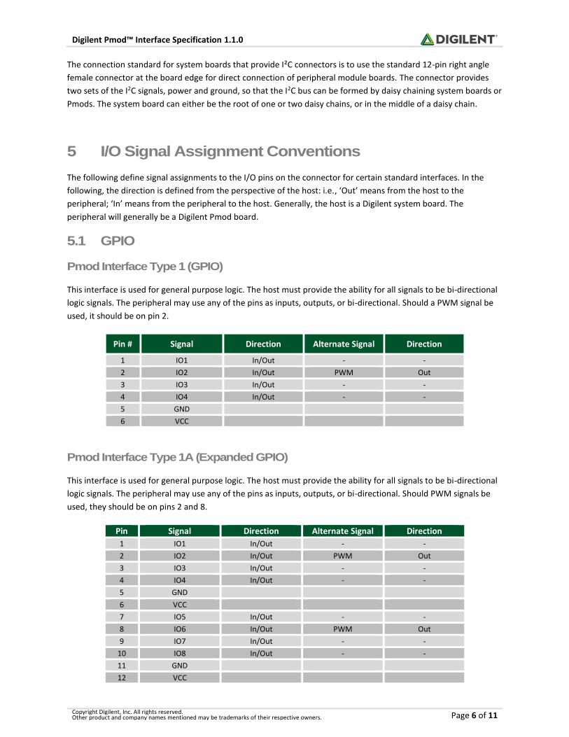
5.1 GPIO
Pmod Interface Type 1 (GPIO)
This interface is used for general purpose logic. The host must provide the ability for all signals to be bi-directional
logic signals. The peripheral may use any of the pins as inputs, outputs, or bi-directional. Should a PWM signal be
used, it should be on pin 2.
Pin # Signal Direction Alternate Signal Direction
1 IO1 In/Out - -
2 IO2 In/Out PWM Out
3 IO3 In/Out - -
4 IO4 In/Out - -
5 GND
6 VCC
Pmod Interface Type 1A (Expanded GPIO)
This interface is used for general purpose logic. The host must provide the ability for all signals to be bi-directional
logic signals. The peripheral may use any of the pins as inputs, outputs, or bi-directional. Should PWM signals be
used, they should be on pins 2 and 8.
Pin Signal Direction Alternate Signal Direction
1 IO1 In/Out - -
2 IO2 In/Out PWM Out
3 IO3 In/Out - -
4 IO4 In/Out - -
5 GND
6 VCC
7 IO5 In/Out - -
8 IO6 In/Out PWM Out
9 IO7 In/Out - -
10 IO8 In/Out - -
11 GND
12 VCC

Digilent Pmod™ Interface Specification 1.1.0
Copyright Digilent, Inc. All rights reserved. Other product and company names mentioned may be trademarks of their respective owners. Page 7 of 11
5.2 SPI
Pmod Interface Type 2 (SPI)
This provides a Serial Peripheral Interface (SPI) port. The host generally acts as an SPI master device and the
peripheral module generally acts as an SPI slave device. When this interface is placed on a 12-pin connector on a
host, it should use pins 1-6 (i.e. the upper row of pins). Pins 1-6 will adhere to the signals listed in the table, with
the exception of one or more pins potentially being unconnected.
Pin Signal Direction
1 CS Out
2 MOSI Out
3 MISO In
4 SCK Out
5 GND
6 VCC
CS - Chip Select. Active low to enable slave device MOSI - Master Out Slave In. Data from master to slave MISO - Master In Slave Out. Data from slave to master SCK - Serial clock. Data clock from master to slave
Pmod Interface Type 2A (expanded SPI)
This provides an SPI interface plus additional control signals. Many SPI devices provide additional control or status
signals that can provide additional functions between the master and slave devices. The host generally acts as an
SPI master device and the peripheral module generally acts as an SPI slave device. Pins 1-6 will not change with the
exception of one or more pins potentially being unconnected. Pins 7-10 can be any signal but if one or more
interrupts are needed they will be on pin 7 and if a reset is needed it will be on pin 8. If additional Chip Select
signals are needed they will be on pins 9 and 10.
Pin # Signal Direction Alternate
Signal Direction
1 CS Out - -
2 MOSI Out - -
3 MISO In - -
4 SCK Out - -
5 GND
6 VCC
7 GPIO In/Out INT In
8 GPIO In/Out RESET Out
9 GPIO In/Out CS2 Out
10 GPIO In/Out CS3 Out
11 GND
12 VCC
CS - Chip Select. Active low to enable slave device MOSI - Master Out Slave In. Data from master to slave MISO - Master In Slave Out. Data from slave to master SCK - Serial clock. Master provides the clock to shift the data INT - Interrupt signal from slave to master

Digilent Pmod™ Interface Specification 1.1.0
Copyright Digilent, Inc. All rights reserved. Other product and company names mentioned may be trademarks of their respective owners. Page 8 of 11
RESET - Reset signal for master to reset slave CS2 - Chip Select 2. Active low to enable second slave device CS3 - Chip Select 3. Active low to enable third slave device
5.3 UART
Pmod Interface Type 3 (UART)
This provides a UART interface with optional hardware flow control. When this interface is placed on a twelve-pin
connector on a host, pins 1-6 should be used (i.e. the upper row of pins). The hardware flow control signals are
optional, and some Pmods do not use them. In this case pins 1 & 4 are either not used or are GPIO.
The hardware flow control signal names are defined from the system board perspective. The RTS signal is an
output indicating that the device (host or peripheral) is ready to receive data. The device asserts this signal low
when it is ready to receive data. The CTS signal is an input to the device (host or peripheral). The device will only
transmit data when the CTS input is asserted low. A peripheral module that uses hardware flow control will
connect the host’s RTS signal to its internal CTS input and the host’s CTS signal to its internal RTS output.
Pin Signal Direction Alternate Signal Direction
1 CTS In GPIO In/Out
2 TXD Out - -
3 RXD In - -
4 RTS Out GPIO In/Out
5 GND GND
6 VCC VCC
CTS - Host is clear to send (will only transmit when this signal is asserted) RTS - Host request to send RXD - Data from peripheral to host TXD - Data from host to peripheral
Pmod Interface Type 3A (expanded UART)
This provides a UART interface with optional hardware flow control plus additional control signals. The hardware
flow control signals are optional, and some Pmods do not use them. In this case pins 1 & 4 are not used or are
GPIO. Pins 7-10 can be any signal, but if one or more interrupts are needed they will be on pin 7 and if a reset is
needed it will be on pin 8.
The hardware flow control signal names are defined from the system board perspective. The RTS signal is an
output indicating that the device (host or peripheral) is ready to receive data. The device asserts this signal low
when it is ready to receive data. The CTS signal is an input to the device (host or peripheral). The device will only
transmit data when the CTS input is asserted low. A peripheral module that uses hardware flow control will
connect the host’s RTS signal to its internal CTS input and the host’s CTS signal to its internal RTS output.

Digilent Pmod™ Interface Specification 1.1.0
Copyright Digilent, Inc. All rights reserved. Other product and company names mentioned may be trademarks of their respective owners. Page 9 of 11
Pin # Signal Direction Alternate Signal Direction
1 CTS In GPIO In/Out
2 TXD Out - -
3 RXD In - -
4 RTS Out GPIO In
5 GND
6 VCC
7 GPIO In/Out INT In
8 GPIO In/Out RESET Out
9 GPIO In/Out - -
10 GPIO In/Out - -
11 GND
12 VCC
CTS - Device will only transmit when this signal is asserted RTS - Device is ready to receive data RXD - Data from peripheral to host TXD - Data from host to peripheral INT - Interrupt signal from peripheral to host RESET - Reset signal for host to reset peripheral
5.4 H-Bridge
Pmod Interface Type 4 (H-Bridge)
This interface provides for controlling a single H-Bridge with motor speed sensing feedback. The DIR pin sets the
rotational direction of the motor. The EN signal is pulse width modulated to control the effective voltage applied to
the motor. EN is an active high signal, i.e. a high logic level enables current flow through the bridge. The SA and SB
signals are quadrature encoder feedback signals used to sense the motor speed. These are square wave signals,
whose frequency is proportional to motor rotational speed and that are in quadrature. (i.e. 90 out of phase). Note
pins 3 and 4 can be left unconnected if feedback is not required.
Pin # Signal Direction
1 DIR Out
2 EN Out
3 SA In
4 SB In
5 GND
6 VCC
DIR - Motor direction EN - Motor enable, active high SA - feedback sense A SB - feedback sense B
Pmod Interface Type 5 (Dual H-Bridge)
This interface provides for controlling two independent H-Bridges. This can be used to control two brushed DC
motors, or the two phases of a bi-polar stepper motor. The EN signal is pulse width modulated to control the
effective voltage applied to the motor. EN is an active high signal, i.e. a high logic level enables current flow
through the bridge.

Digilent Pmod™ Interface Specification 1.1.0
Copyright Digilent, Inc. All rights reserved. Other product and company names mentioned may be trademarks of their respective owners. Page 10 of 11
Pin # Signal Direction
1 DIR1 Out
2 EN1 Out
3 DIR2 Out
4 EN2 Out
5 GND
6 VCC
DIR1 - Motor/Phase 1 direction EN1 - Motor/Phase 1 enable, active high DIR2 - Motor/Phase 2 direction EN2 - Motor/Phase 2 enable, active high
Pmod Interface Type 5A (Expanded Dual H-Bridge)
This interface provides for controlling two independent H-Bridges with motor speed sensing feedback. The DIR pin
sets the rotational direction of the motor. The EN signal is pulse width modulated to control the effective voltage
applied to the motor. EN is an active high signal, i.e. a high logic level enables current flow through the bridge. The
SA and SB signals are quadrature encoder feedback signals used to sense the motor speed. These are square wave
signals, whose frequency is proportional to motor rotational speed and that are in quadrature. (i.e. 90 out of
phase).
Pin # Signal Direction
1 DIR1 Out
2 EN1 Out
3 S1A In
4 S1B In
5 GND
6 VCC
7 DIR2 Out
8 EN2 Out
9 S2A In
10 S2B In
11 GND
12 VCC
DIR1 - Motor 1 direction EN1 - Motor 1 enable, active high SA1 - Motor 1 feedback sense A SB1 - Motor 1 feedback sense B DIR2 - Motor 2 direction EN2 - Motor 2 enable, active high SA2 - Motor 2 feedback sense A SB2 - Motor 2 feedback sense B

Digilent Pmod™ Interface Specification 1.1.0
Copyright Digilent, Inc. All rights reserved. Other product and company names mentioned may be trademarks of their respective owners. Page 11 of 11
5.5 I²C
Pmod Interface Type 6 (I²C)
This interface conforms to the I2C specification, plus an optional interrupt and reset pin. If these optional pins are
not used, they will be no connects. The pull-up resistors used to provide the logic high level for SCL and SDA are
provided on the modules and can be attached to or detached from the bus via onboard jumpers. Pull-ups on INT
and RESET, if used, are also provided on the module and can be attached or detached from the bus via onboard
jumpers to enable daisy chaining.
Pin # Signal Direction Alternate Signal
1 NC INT
2 NC RESET
3 SCL In/Out -
4 SDA In/Out -
5 GND
6 VCC
SCL – Serial Clock SDA – Serial Data NC – Not Connected INT – Open drain, active low, interrupt signal from slave to master. RESET – active low reset signal from master to slave. The system board is the master.
5.6 I2S
Pmod Interface Type 7 (I²S CODEC)
This provides the standard connections for an I²S codec interface, plus an optional clock signal used by some I²S
devices.
Pin #
Signal Direction Alternate Signal Direction
1 LRCLK Out - -
2 DAC Data Out - -
3 ADC Data In - -
4 BCLK Out - -
5 GND
6 VCC
7 GPIO -
8 GPIO -
9 GPIO - MCLK Out
10 GPIO -
11 GND
12 VCC
LRCLK - Left channel/Right channel select DAC Data - Output data to DAC ADC Data - Input Data from ADC BCLK - Serial bit clock. MCLK - Optional master clock used by some I2S devices