diaphragm actuators
TRANSCRIPT
WEIR CONTROL & CHOKE VALVES ExcellentPower & IndustrialSolutions
ExcellentEngineeringSolutions
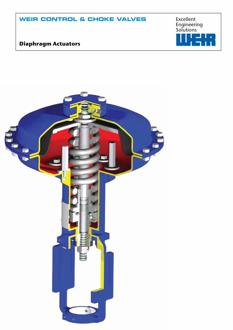
Diaphragm Actuators
www.weirpowerindustrial.comWeir Control & Choke valves Engineered valves for protection & process control
Weir Control & Choke Valves Diaphragm Actuators
2
ContentsGeneral description 3Major components 4Actuator operation 5RAD & RAR actuator dimensions 6RAD & RAR technical data 7Multi spring actuators 8A60 & A61 Series 9A60 & A61 actuator dimensions 10A60 & A61 technical data 11Configuration 13
Quality assuranceWeir is qualified to industry standards and working practices including:
� ASME BPVC Section III (N and NPT Stamp) � NQA-1 Quality system � 10CFR50 App. B � 10CFR50 Part 21 � RCC-E � RCC-M � CSA Z299 � Performance testing and qualification to:ASME QME-1ASME B16.41IEEE 323IEEE 344IEEE 382
� ISO 9001:2008 � ISO 14001 � PED 97/23/CE � API Q1 TO API LICENCES:
API 6D (6D-0182)API 6A (64-0445)
� OHSAS 18001 � ATEX 94/9/CE � Lean manufacturing practices
A proven track recordWe have extensive references and a proven track record in the supply of valves across a number of key industries.
Our valves are industry renowned brands, each with an established reputation for quality engineering and reliability.
Valve testingAll pressure containing items are hydrostatically tested, seat leakage tested and functionally tested.
We can also perform gas, packing emission, cryogenic and advanced functional testing, as well as seismic testing for nuclear applications.
Material testing � Non-destructive examination by radiography, ultrasonics, magnetic particle and liquid penetrant.
� Chemical analysis by computer controlled direct reading emission spectrometer.
� Mechanical testing for tensile properties at ambient and elevated temperatures, bend and hardness testing. Charpy testing at ambient, elevated and sub-zero temperatures.
Aftermarket solutionsOur valve aftermarket solutions are based on our engineering heritage, applying our OEM knowledge and expertise to maintenance strategies, life extension and upgrade projects.
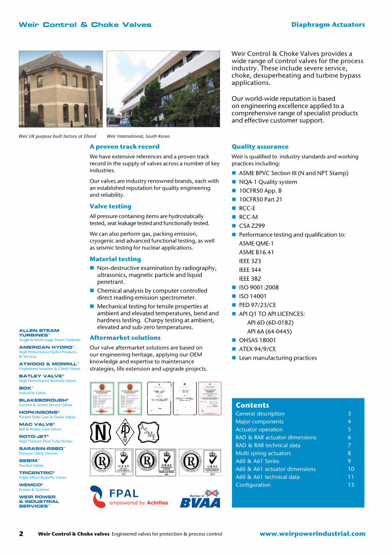
Weir Control & Choke Valves provides a wide range of control valves for the process industry. These include severe service, choke, desuperheating and turbine bypass applications. Our world-wide reputation is based on engineering excellence applied to a comprehensive range of specialist products and effective customer support.
Weir UK purpose built factory at Elland
Member of
Weir International, South Korea
Weir Control & Choke valves Engineered valves for protection & process control 3www.weirpowerindustrial.com
Weir Control & Choke Valves Single Spring Diaphragm Actuators
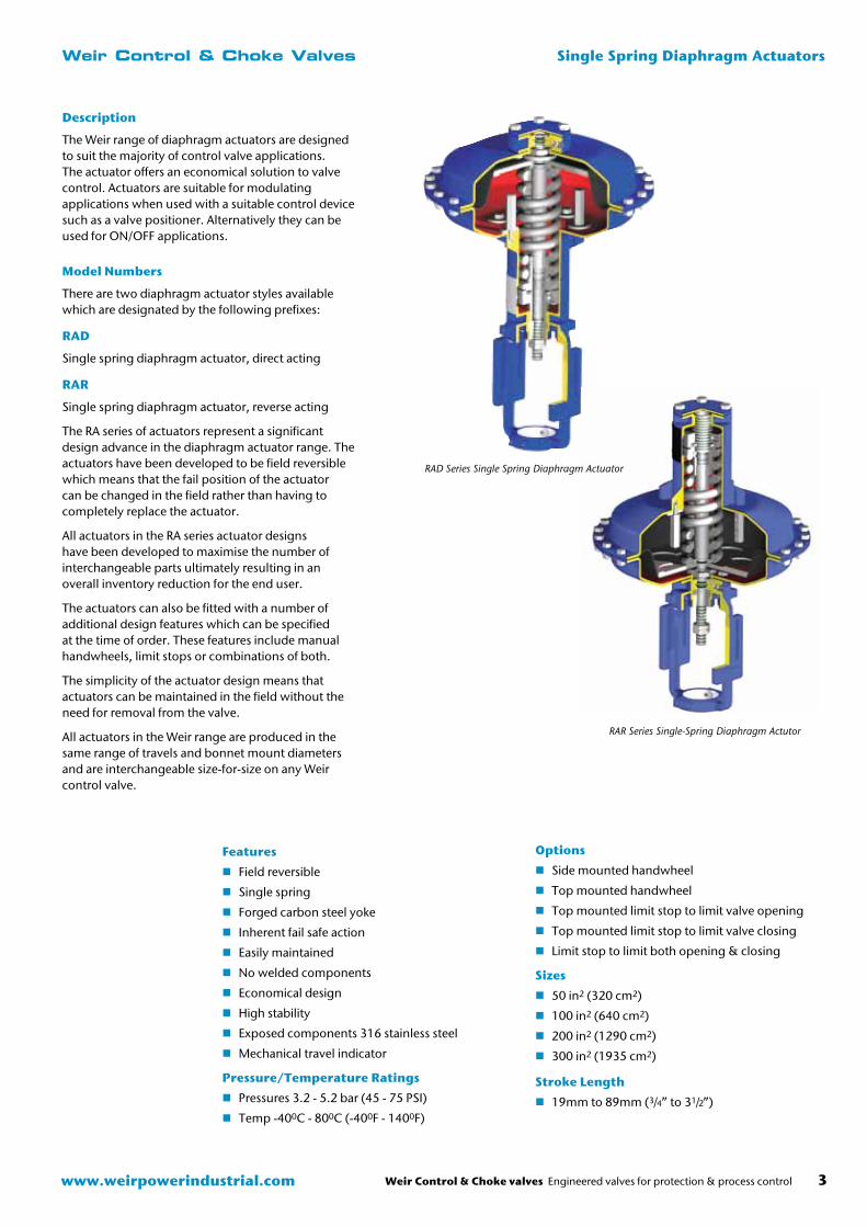
RAR Series Single-Spring Diaphragm Actutor
Features
� Field reversible
� Single spring
� Forged carbon steel yoke
� Inherent fail safe action
� Easily maintained
� No welded components
� Economical design
� High stability
� Exposed components 316 stainless steel
� Mechanical travel indicator
Pressure/Temperature Ratings
� Pressures 3.2 - 5.2 bar (45 - 75 PSI)
� Temp -400C - 800C (-400F - 1400F)
Model Numbers
There are two diaphragm actuator styles available which are designated by the following prefixes:
RAD
Single spring diaphragm actuator, direct acting
RAR
Single spring diaphragm actuator, reverse acting
The RA series of actuators represent a significant design advance in the diaphragm actuator range. The actuators have been developed to be field reversible which means that the fail position of the actuator can be changed in the field rather than having to completely replace the actuator.
All actuators in the RA series actuator designs have been developed to maximise the number of interchangeable parts ultimately resulting in an overall inventory reduction for the end user.
The actuators can also be fitted with a number of additional design features which can be specified at the time of order. These features include manual handwheels, limit stops or combinations of both.
The simplicity of the actuator design means that actuators can be maintained in the field without the need for removal from the valve.
All actuators in the Weir range are produced in the same range of travels and bonnet mount diameters and are interchangeable size-for-size on any Weir control valve.
Description
The Weir range of diaphragm actuators are designed to suit the majority of control valve applications. The actuator offers an economical solution to valve control. Actuators are suitable for modulating applications when used with a suitable control device such as a valve positioner. Alternatively they can be used for ON/OFF applications.
Options
� Side mounted handwheel
� Top mounted handwheel
� Top mounted limit stop to limit valve opening
� Top mounted limit stop to limit valve closing
� Limit stop to limit both opening & closing
Sizes
� 50 in2 (320 cm2)
� 100 in2 (640 cm2)
� 200 in2 (1290 cm2)
� 300 in2 (1935 cm2)
Stroke Length
� 19mm to 89mm (3/4” to 31/2”)
RAD Series Single Spring Diaphragm Actuator
www.weirpowerindustrial.comWeir Control & Choke valves Engineered valves for protection & process control
Weir Control & Choke Valves Single Spring Diaphragm Actuators
4
Major Components
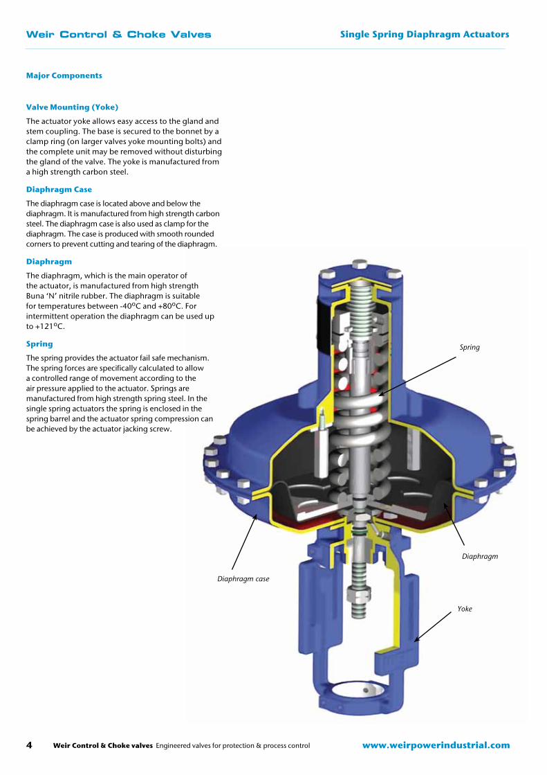
Valve Mounting (Yoke)
The actuator yoke allows easy access to the gland and stem coupling. The base is secured to the bonnet by a clamp ring (on larger valves yoke mounting bolts) and the complete unit may be removed without disturbing the gland of the valve. The yoke is manufactured from a high strength carbon steel.
Diaphragm Case
The diaphragm case is located above and below the diaphragm. It is manufactured from high strength carbon steel. The diaphragm case is also used as clamp for the diaphragm. The case is produced with smooth rounded corners to prevent cutting and tearing of the diaphragm.
Diaphragm
The diaphragm, which is the main operator of the actuator, is manufactured from high strength Buna ‘N’ nitrile rubber. The diaphragm is suitable for temperatures between -40oC and +80oC. For intermittent operation the diaphragm can be used up to +121oC.
Spring
The spring provides the actuator fail safe mechanism. The spring forces are specifically calculated to allow a controlled range of movement according to the air pressure applied to the actuator. Springs are manufactured from high strength spring steel. In the single spring actuators the spring is enclosed in the spring barrel and the actuator spring compression can be achieved by the actuator jacking screw.
Diaphragm case
Diaphragm
Spring
Yoke
Weir Control & Choke valves Engineered valves for protection & process control 5www.weirpowerindustrial.com
Weir Control & Choke Valves Single Spring Diaphragm Actuators
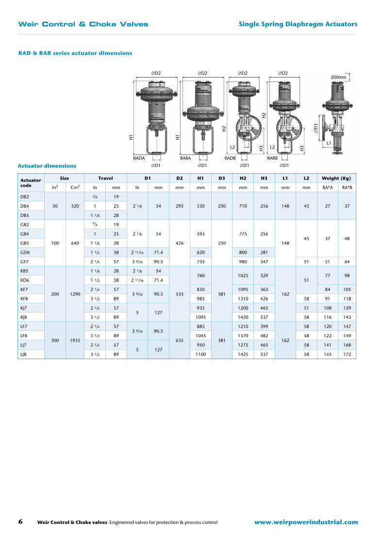
Actuator Operation (Fail Action)
The diaphragm actuator is produced in two basic forms, direct and reverse acting. The selection of the correct actuator action is according to the required air fail condition on site. The reverse acting actuator (RAR series actuator), when fitted to a push down to close valve relies on air to open the valve. On air failure the air will vent from the actuator and the valve will close.
The direct acting actuator (RAD series actuator), when fitted to a push down to close valve relies on air to close the valve. On air failure the air will vent from the actuator and the valve will open.
It has become apparent that it is sometimes a site requirement to change the ‘fail safe’ operation of the valve. To satisfy this requirement the RA series of actuators has been developed which can be reversed in the field by simply reversing the orientation of the diaphragm.
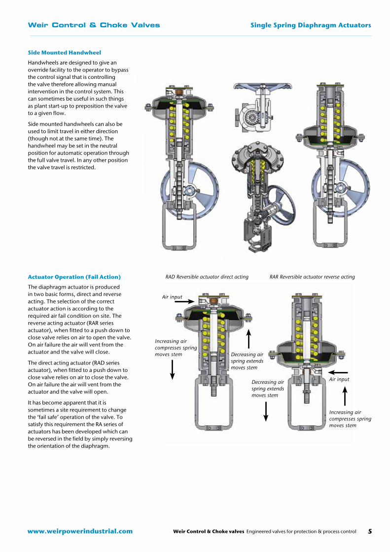
Side Mounted Handwheel
Handwheels are designed to give an override facility to the operator to bypass the control signal that is controlling the valve therefore allowing manual intervention in the control system. This can sometimes be useful in such things as plant start-up to preposition the valve to a given flow.
Side mounted handwheels can also be used to limit travel in either direction (though not at the same time). The handwheel may be set in the neutral position for automatic operation through the full valve travel. In any other position the valve travel is restricted.
Increasing air compresses spring moves stem Decreasing air
spring extends moves stem
RAD Reversible actuator direct acting RAR Reversible actuator reverse acting
Increasing air compresses spring moves stem
Decreasing air spring extends moves stem
Air input
Air input
www.weirpowerindustrial.comWeir Control & Choke valves Engineered valves for protection & process control
Weir Control & Choke Valves Single Spring Diaphragm Actuators
6
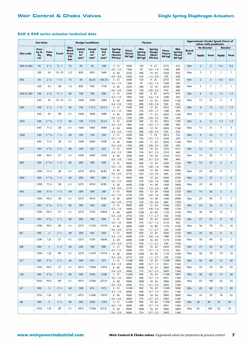
Actuator dimensions
Actuator code
Size Travel D1 D2 H1 D3 H2 H3 L1 L2 Weight (Kg)
In2 Cm2 In mm In mm mm mm mm mm mm mm mm RA*A RA*B
DB2
50 320
3/4 19
2 1/8 54 295 530 250 710 256 148 45 27 37DB4 1 25
DB5 1 1/8 28
GB2
100 640
3/4 19
2 1/8 54
426
595
250
775 256
14845 37 48
GB4 1 25
GB5 1 1/8 28
GD6 1 1/2 38 2 11/16 71.4 620 800 281
GF7 2 1/4 57 3 9/16 90.5 735 980 347 51 51 64
KB5
200 1290
1 1/8 28 2 1/8 54
533
760
381
1025 329
162
5177 98
KD6 1 1/2 38 2 11/16 71.4
KF7 2 1/4 573 9/16 90.5
830 1095 363 84 105
KF8 3 1/2 89 985 1310 426 58 91 118
KJ7 2 1/4 575 127
935 1200 465 51 108 129
KJ8 3 1/2 89 1095 1420 537 58 116 143
LF7
300 1935
2 1/4 573 9/16 90.5
635
885
381
1210 399
162
58 120 147
LF8 3 1/2 89 1045 1370 482 58 122 149
LJ7 2 1/4 575 127
950 1275 465 58 141 168
LJ8 3 1/2 89 1100 1425 537 58 145 172
∅D1 ∅D1 ∅D1 ∅D1
∅D2 ∅D2 ∅D2 ∅D2
H2
H2
H3
H3
H1
H1
L2L2L1
RADA RARA RADB RARB
∅D
3
RAD & RAR series actuator dimensions
200mm
Weir Control & Choke valves Engineered valves for protection & process control 7www.weirpowerindustrial.com
Weir Control & Choke Valves Single Spring Diaphragm Actuators
RAD & RAR series actuator technical data
Size Data Design Conditions Thrusts Approximate Stroke Speed (Secs) of valves with positioner
Size code
AreaSq in
Sq cm
YokeMtg Travel
Max WorkPressPSI bar
Initial Vol in3
mm3
Swept Volin3
mm3
Total Volin3
mm3
Spring Range
(Norm) PSI bar
Pneu. Thrustlbf kgf
Min Spring Thrustlbf kgf
Spring Range (Max)
PSI bar
Pneu. Thrustlbf kgf
Min Spring Thrustlbf kgf
Bench Set
No Booster Booster
Apply Vent Apply Vent
DB2 & DB4 50 2 1/4 3/4 - 1 75 50 50 100 3 - 150.2 - 1.0
6 - 300.4 - 2.0
3000136022501020
15070
300140
9 - 210.6 - 1.419 - 43
1.3 - 2.9
273512401650750
435200940430
Min 2 4 0.5 0.5
320 54 19 - 25 5.2 820 820 1640 Max 5 7 1 1
DB5 50 2 1/8 1 1/8 75 50 56.25 106.25 3 - 150.2 - 1.0
6 - 300.4 - 2.0
3000136022501020
15070
300140
9 - 210.6 - 1.412 - 35
0.8 - 2.4
273512402010910
435200580260
Min 2 4 0.5 0.5
320 54 28 5.2 820 920 1740 Max 5 7 1 1
GB2 & GB4 100 2 1/8 3/4 - 1 60 100 100 200 3 - 150.2 - 1.0
6 - 300.4 - 2.0
4500198430001350
300140600280
9 - 210.6 - 1.412 - 35
0.8 - 2.4
347015802020920
870395
1160530
Min 6 12 1.5 1.5
640 54 19 - 25 4.1 1640 1640 3280 Max 13 21 3 3
GB5 100 2 1/8 1 1/8 60 100 112.5 212.5 3 - 150.2 - 1.0
6 - 300.4 - 2.0
4500198430001350
300140600280
12 - 250.9 - 1.711 - 35
0.8 - 2.4
303513802020920
1305590
1160530
Min 6 12 1.5 1.5
640 54 28 4.1 1640 1840 3480 Max 13 21 3 3
GD5 100 2 13/16 1 1/8 60 100 112.5 212.5 3 - 150.2 - 1.0
6 - 300.4 - 2.0
4500198430001350
300140600280
12 - 250.9 - 1.712 - 35
0.8 - 2.4
303513802020920
1305590
1160530
Min 6 12 1.5 1.5
640 71.2 28 4.1 1640 1840 3480 Max 13 21 3 3
GD6 100 2 13/16 1 1/2 60 100 150 250 3 - 150.2 - 1.0
6 - 300.4 - 2.0
4500198430001350
300140600280
7 - 190.5 - 1.311 - 35
0.8 - 2.4
361516402020920
725330
1160530
Min 9 12 3 3
640 71.4 38 4.1 1640 2460 4100 Max 12 25 5 5
GF7 100 3 9/16 2 1/4 60 100 225 325 3 - 150.2 - 1.0
6 - 300.4 - 2.0
4500198430001350
300140600280
10 - 220.7 - 2.310 - 34
0.7 - 2.3
332515102165985
1015460
1015460
Min 12 15 4 5
640 90.5 57 4.1 1640 3690 5330 Max 15 30 7 7
KB5 200 2 13/16 1 1/2 60 200 300 500 3 - 150.2 - 1.0
6 - 300.4 - 2.0
9000400060002710
600270
1200550
12 - 240.8 - 1.614 - 38
1.0 - 2.6
436019801460660
2320172029001320
Min 16 32 5 5
1290 71.4 38 4.1 3275 4910 8185 Max 23 40 9 7
KD6 200 2 13/16 1 1/2 60 200 300 500 3 - 150.2 - 1.0
6 - 300.4 - 2.0
9000400060002710
600270
1200550
12 - 240.8 - 1.614 - 38
1.0 - 2.6
436019801460660
2320172029001320
Min 16 32 5 5
1290 71.4 38 4.1 3275 4910 8185 Max 23 40 9 7
KF6 200 3 9/16 1 1/2 60 200 300 500 3 - 150.2 - 1.0
6 - 300.4 - 2.0
9000273060002710
600270
1200550
12 - 240.8 - 1.614 - 38
1.0 - 2.6
436019801460660
2320172029001320
Min 16 36 5 5
1290 90.5 38 4.1 3275 4910 8185 Max 23 40 9 7
KF7 200 3 9/16 2 1/4 60 200 450 650 3 - 150.2 - 1.0
6 - 300.4 - 2.0
9000400060002710
600270
1200550
12 - 240.8 - 1.616 - 40
1.1 - 2.7
436019801170530
2320172031901450
Min 24 36 6 6
1290 90.5 57 4.1 3275 7370 10645 Max 36 40 12 7
KF8 200 3 9/16 3 1/2 60 200 700 900 3 - 150.2 - 1.0
6 - 300.4 - 2.0
9000400060002710
600270
1200550
10 - 220.7 - 1.516 - 40
1.1 - 2.7
465021101170530
2030920
31901450
Min 27 54 8 10
1290 90.5 89 4.1 3275 11470 14745 Max 56 70 10 16
KJ7 200 5 2 1/4 60 200 450 650 3 - 150.2 - 1.0
6 - 300.4 - 2.0
9000400060002710
600270
1200550
12 - 240.8 - 1.616 - 40
1.1 - 2.7
436019801170530
2320172031901450
Min 24 36 6 6
1290 125 57 4.1 3275 7370 10645 Max 36 40 12 7
KJ8 200 5 3 1/2 60 200 700 900 3 - 150.2 - 1.0
6 - 300.4 - 2.0
9000400060002710
600270
1200550
10 - 220.7 - 1.516 - 40
1.1 - 2.7
465021101170530
2030920
31901450
Min 27 54 8 10
1290 125 89 4.1 3275 11470 14745 Max 56 70 10 16
LF7 300 3 9/16 2 1/4 60 300 675 975 3 - 150.2 - 1.0
6 - 300.4 - 2.0
13500600090004060
900408
1800774
10 - 220.7 - 1.510 - 34
0.7 - 2.3
11400503178003483
3000136030001360
Min 45 60 15 20
1935 90.5 57 4.1 4915 11060 15975 Max 55 70 18 25
LF8 300 3 9/16 3 1/2 60 300 1050 1350 3 - 150.2 - 1.0
6 - 300.4 - 2.0
13500600090004060
900408
1800774
10 - 220.7 - 1.510 - 34
0.7 - 2.3
11400503178003483
3000136030001360
Min 50 82 19 30
1935 90.5 89 4.1 4915 17206 22121 Max 65 100 22 33
LJ7 300 5 2 1/4 60 300 675 975 3 - 150.2 - 1.0
6 - 300.4 - 2.0
13500600090004060
900408
1800774
10 - 220.7 - 1.510 - 34
0.7 - 2.3
11400503178003483
3000136030001360
Min 45 60 15 20
1935 125 57 4.1 4915 11060 15975 Max 55 70 18 25
LJ8 300 5 3 1/2 60 300 1050 1350 3 - 150.2 - 1.0
6 - 300.4 - 2.0
13500600090004060
900408
1800774
10 - 220.7 - 1.510 - 34
0.7 - 2.3
11400503178003483
3000136030001360
Min 50 82 19 30
1935 125 89 4.1 4915 17206 22121 Max 65 100 22 33
www.weirpowerindustrial.comWeir Control & Choke valves Engineered valves for protection & process control
Weir Control & Choke Valves Multi Spring Diaphragm Actuators
8
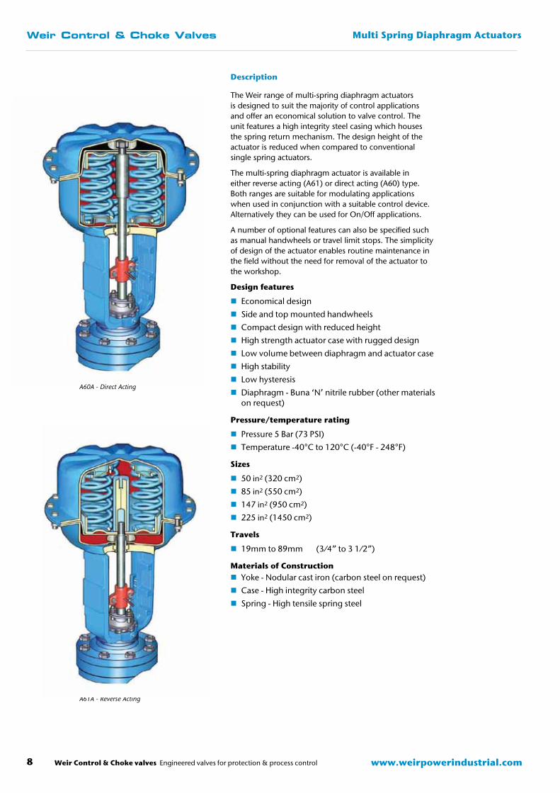
Description
The Weir range of multi-spring diaphragm actuators is designed to suit the majority of control applications and offer an economical solution to valve control. The unit features a high integrity steel casing which houses the spring return mechanism. The design height of the actuator is reduced when compared to conventional single spring actuators.
The multi-spring diaphragm actuator is available in either reverse acting (A61) or direct acting (A60) type. Both ranges are suitable for modulating applications when used in conjunction with a suitable control device. Alternatively they can be used for On/Off applications.
A number of optional features can also be specified such as manual handwheels or travel limit stops. The simplicity of design of the actuator enables routine maintenance in the field without the need for removal of the actuator to the workshop.
Design features
� Economical design
� Side and top mounted handwheels
� Compact design with reduced height
� High strength actuator case with rugged design
� Low volume between diaphragm and actuator case
� High stability
� Low hysteresis
� Diaphragm - Buna ‘N’ nitrile rubber (other materials on request)
Pressure/temperature rating
� Pressure 5 Bar (73 PSI)
� Temperature -40°C to 120°C (-40°F - 248°F)
Sizes
� 50 in2 (320 cm2)
� 85 in2 (550 cm2)
� 147 in2 (950 cm2)
� 225 in2 (1450 cm2)
Travels
� 19mm to 89mm (3⁄4” to 3 1⁄2”)
Materials of Construction � Yoke - Nodular cast iron (carbon steel on request)
� Case - High integrity carbon steel
� Spring - High tensile spring steel
A60A - Direct Acting
A61A - Reverse Acting
Weir Control & Choke valves Engineered valves for protection & process control 9www.weirpowerindustrial.com
Weir Control & Choke Valves Multi Spring Diaphragm Actuators
A60 & A61 Series
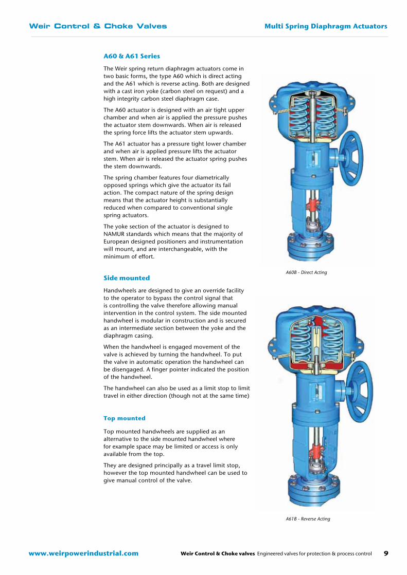
The Weir spring return diaphragm actuators come in two basic forms, the type A60 which is direct acting and the A61 which is reverse acting. Both are designed with a cast iron yoke (carbon steel on request) and a high integrity carbon steel diaphragm case.
The A60 actuator is designed with an air tight upper chamber and when air is applied the pressure pushes the actuator stem downwards. When air is released the spring force lifts the actuator stem upwards.
The A61 actuator has a pressure tight lower chamber and when air is applied pressure lifts the actuator stem. When air is released the actuator spring pushes the stem downwards.
The spring chamber features four diametrically opposed springs which give the actuator its fail action. The compact nature of the spring design means that the actuator height is substantially reduced when compared to conventional single spring actuators.
The yoke section of the actuator is designed to NAMUR standards which means that the majority of European designed positioners and instrumentation will mount, and are interchangeable, with the minimum of effort.
Side mounted
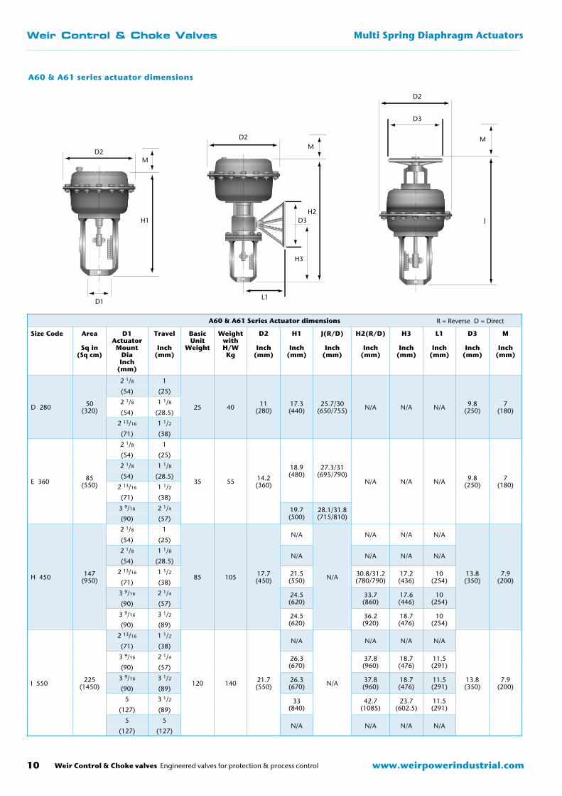
Handwheels are designed to give an override facility to the operator to bypass the control signal that is controlling the valve therefore allowing manual intervention in the control system. The side mounted handwheel is modular in construction and is secured as an intermediate section between the yoke and the diaphragm casing.
When the handwheel is engaged movement of the valve is achieved by turning the handwheel. To put the valve in automatic operation the handwheel can be disengaged. A finger pointer indicated the position of the handwheel.
The handwheel can also be used as a limit stop to limit travel in either direction (though not at the same time)
Top mounted
Top mounted handwheels are supplied as an alternative to the side mounted handwheel where for example space may be limited or access is only available from the top.
They are designed principally as a travel limit stop, however the top mounted handwheel can be used to give manual control of the valve.
A60B - Direct Acting
A61B - Reverse Acting
www.weirpowerindustrial.comWeir Control & Choke valves Engineered valves for protection & process control
Weir Control & Choke Valves Multi Spring Diaphragm Actuators
10
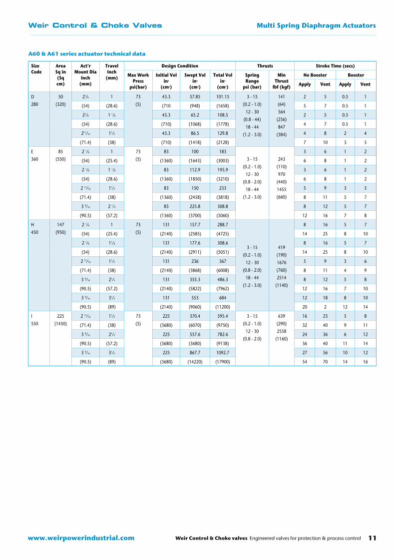
A60 & A61 Series Actuator dimensions
Size Code Area
Sq in(Sq cm)
D1Actuator
Mount DiaInch
(mm)
Travel
Inch(mm)
Basic Unit
Weight
Weight with H/WKg
D2
Inch(mm)
H1
Inch(mm)
J(R/D)
Inch(mm)
H2(R/D)
Inch(mm)
H3
Inch(mm)
L1
Inch(mm)
D3
Inch(mm)
M
Inch(mm)
D 280 50(320)
2 1/8 1
25 40 11(280)
17.3(440)
25.7/30(650/755) N/A N/A N/A 9.8
(250)7
(180)
(54) (25)
2 1/8 1 1/8
(54) (28.5)
2 13/16 1 1/2
(71) (38)
E 360 85(550)
2 1/8 1
35 55 14.2(360)
18.9(480)
27.3/31(695/790)
N/A N/A N/A 9.8(250)
7(180)
(54) (25)
2 1/8 1 1/8
(54) (28.5)
2 13/16 1 1/2
(71) (38)
3 9/16 2 1/4 19.7(500)
28.1/31.8(715/810)(90) (57)
H 450 147(950)
2 1/8 1
85 105 17.7(450)
N/A
N/A
N/A N/A N/A
13.8(350)
7.9(200)
(54) (25)
2 1/8 1 1/8N/A N/A N/A N/A
(54) (28.5)
2 13/16 1 1/2 21.5(550)
30.8/31.2(780/790)
17.2(436)
10(254)(71) (38)
3 9/16 2 1/4 24.5(620)
33.7(860)
17.6(446)
10(254)(90) (57)
3 9/16 3 1/2 24.5(620)
36.2(920)
18.7(476)
10(254)(90) (89)
I 550 225(1450)
2 13/16 1 1/2
120 140 21.7(550)
N/A
N/A
N/A N/A N/A
13.8(350)
7.9(200)
(71) (38)
3 9/16 2 1/4 26.3(670)
37.8(960)
18.7(476)
11.5(291)(90) (57)
3 9/16 3 1/2 26.3(670)
37.8(960)
18.7(476)
11.5(291)(90) (89)
5 3 1/2 33(840)
42.7(1085)
23.7(602.5)
11.5(291)(127) (89)
5 5N/A N/A N/A N/A
(127) (127)
D
D2
D2M
M
M
D3
D3 JH2
H1
H3
L1
A60 & A61 series actuator dimensions
R = Reverse D = Direct
D2
D1
SizeCode
AreaSq in(Sq cm)
Act’rMount Dia
Inch(mm)
TravelInch
(mm)
Design Condition Thrusts Stroke Time (secs)
Max WorkPress
psi(bar)
Initial Volin3
(cm3)
Swept Volin3
(cm3)
Total Volin3
(cm3)
SpringRange
psi (bar)
MinThrust
lbf (kgf)
No Booster Booster
Apply Vent Apply Vent
D
280
50
(320)
21⁄8 1 73
(5)
43.3 57.85 101.15 3 - 15
(0.2 - 1.0)
12 - 30
(0.8 - 44)
18 - 44
(1.2 - 3.0)
141
(64)
564
(256)
847
(384)
2 5 0.5 1
(54) (28.6) (710 (948) (1658) 5 7 0.5 1
21⁄8 1 1⁄8 43.3 65.2 108.5 2 5 0.5 1
(54) (28.6) (710) (1068) (1778) 4 7 0.5 1
211⁄16 11⁄2 43.3 86.5 129.8 4 8 2 4
(71.4) (38) (710) (1418) (2128) 7 10 3 5
E
360
85
(550)
2 1⁄8 1 73
(5)
83 100 183
3 - 15
(0.2 - 1.0)
12 - 30
(0.8 - 2.0)
18 - 44
(1.2 - 3.0)
243
(110)
970
(440)
1455
(660)
3 6 1 2
(54) (25.4) (1360) (1643) (3003) 6 8 1 2
2 1⁄8 1 1⁄8 83 112.9 195.9 3 6 1 2
(54) (28.6) (1360) (1850) (3210) 6 8 1 2
2 13⁄16 11⁄2 83 150 233 5 9 3 5
(71.4) (38) (1360) (2458) (3818) 8 11 5 7
3 9⁄16 2 1⁄4 83 225.8 308.8 8 12 5 7
(90.5) (57.2) (1360) (3700) (5060) 12 16 7 8
H
450
147
(950)
2 1⁄8 1 73
(5)
131 157.7 288.7
3 - 15
(0.2 - 1.0)
12 - 30
(0.8 - 2.0)
18 - 44
(1.2 - 3.0)
419
(190)
1676
(760)
2514
(1140)
8 16 5 7
(54) (25.4) (2140) (2585) (4725) 14 25 8 10
2 1⁄8 11⁄8 131 177.6 308.6 8 16 5 7
(54) (28.6) (2140) (2911) (5051) 14 25 8 10
2 13⁄16 11⁄2 131 236 367 5 9 3 6
(71.4) (38) (2140) (3868) (6008) 8 11 4 9
3 9⁄16 21⁄4 131 355.3 486.3 8 12 5 8
(90.5) (57.2) (2140) (5822) (7962) 12 16 7 10
3 9⁄16 31⁄2 131 553 684 12 18 8 10
(90.5) (89) (2140) (9060) (11200) 20 2 12 14
I
550
225
(1450)
2 13⁄16 11⁄2 73
(5)
225 370.4 595.4 3 - 15
(0.2 - 1.0)
12 - 30
(0.8 - 2.0)
639
(290)
2558
(1160)
16 23 5 8
(71.4) (38) (3680) (6070) (9750) 32 40 9 11
3 9⁄16 21⁄4 225 557.6 782.6 24 36 6 12
(90.5) (57.2) (3680) (3680) (9138) 36 40 11 14
3 9⁄16 31⁄2 225 867.7 1092.7 27 56 10 12
(90.5) (89) (3680) (14220) (17900) 54 70 14 16
Weir Control & Choke valves Engineered valves for protection & process control 11www.weirpowerindustrial.com
Weir Control & Choke Valves Multi Spring Diaphragm Actuators
A60 & A61 series actuator technical data
www.weirpowerindustrial.comWeir Control & Choke valves Engineered valves for protection & process control
Weir Control & Choke Valves Diaphragm Actuators
12
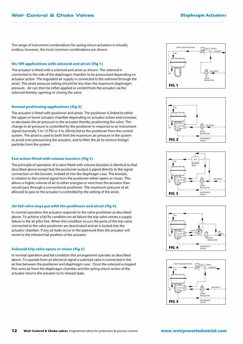
The range of instrument combinations for spring return actuators is virtually endless, however, the most common combinations are shown.
On/Off applications with solenoid and airset (Fig 1)
The actuator is fitted with a solenoid and airset as shown. The solenoid is connected to the side of the diaphragm chamber to be pressurised depending on actuator action. The regulated air supply is connected to the solenoid through the airset. The airset pressure setting should be less than the maximum diaphragm pressure. Air can then be either applied or vented from the actuator via the solenoid thereby opening or closing the valve.
Normal positioning applications (Fig 2)
The actuator is fitted with positioner and airset. The positioner is linked to either the upper or lower actuator chamber depending on actuator action and increases or decreases the air pressure to the actuator thereby positioning the valve. The change in air pressure is controlled by the positioner in response to an instrument signal (normally 3 to 15 PSI or 4 to 20mA) fed to the positioner from the control system. The airset is used to both limit the maximum air pressure in the system to avoid over-pressurising the actuator, and to filter the air to remove foreign particles from the system.
Fast action fitted with volume boosters (Fig 3)
The principle of operation of a valve fitted with volume boosters is identical to that described above except that the positioner output is piped directly to the signal connection on the booster, instead of into the diaphragm case. The booster, in relation to the control signal from the positioner either opens or closes. This allows a higher volume of air to either energise or vent from the actuator than would pass through a conventional positioner. The maximum pressure of air allowed to pass to the actuator is controlled by the setting of the airset.
Air fail valve stays put with the positioner and airset (Fig 4)
In normal operation the actuator responds to the valve positioner as described above. To achieve a fail fix condition on air failure the trip valve senses a supply failure in the air pilot line. When this condition occurs the ports of the trip valve connected to the valve positioner are deactivated and air is locked into the actuator chamber. If any air leaks occur in the pipework then the actuator will revert to the inherent fail position of the actuator.
Solenoid trip valve opens or closes (Fig 5)
In normal operation and fail condition this arrangement operates as described above. To operate from an electrical signal a solenoid valve is connected in the air line between the positioner and diaphragm case. Once the solenoid is tripped this vents air from the diaphragm chamber and the spring return action of the actuator returns the actuator to its relaxed state.
FIG 1
RA
DA
3-WAY SOLENOID VALVEELECT. SUPPLY
AC
BEXHAUST
AIR SUPPLY
FILTERREGULATOR
FIG 2
RA
DA
AIR SUPPLY
FILTERREGULATOR
INSTRUMENTSIGNAL
P0POSITIONER1A P1
FIG 3
RA
DA
AIR SUPPLY
FILTERREGULATOR
INSTRUMENTSIGNAL
P0POSITIONER1A P1
61H
BOOSTERRELAY
FIG 4
RA
DA
INSTRUMENTSIGNAL
P0POSITIONER1A P1
AIRSUPPLY
FILTERREGULATOR
AC61A
A
BC
FIG 5
RA
DA
AIR SUPPLY
FILTERREGULATOR
INSTRUMENTSIGNAL
P0POSITIONER1A P1
ELECT. SUPPLYAC
BEXHAUST
3-WAY SOLENOID VALVE
Weir Control & Choke valves Engineered valves for protection & process control 13www.weirpowerindustrial.com
Weir Control & Choke Valves Diaphragm Actuators
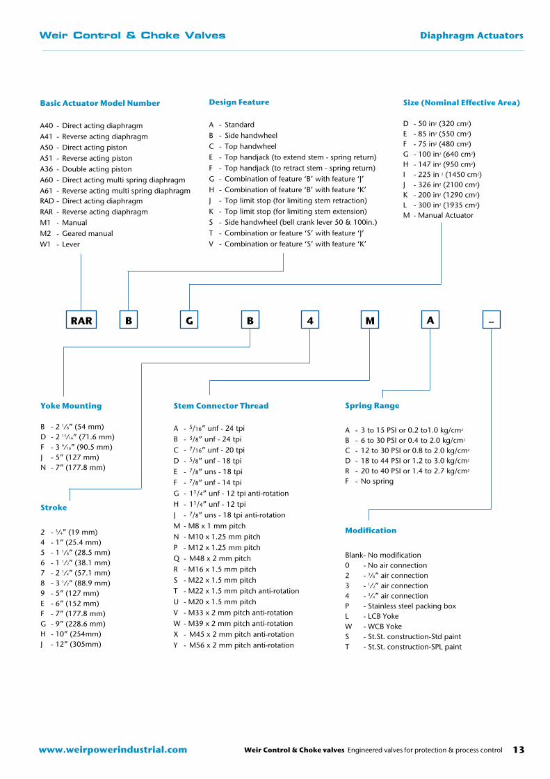
Basic Actuator Model Number
A40 - Direct acting diaphragmA41 - Reverse acting diaphragmA50 - Direct acting pistonA51 - Reverse acting pistonA36 - Double acting pistonA60 - Direct acting multi spring diaphragmA61 - Reverse acting multi spring diaphragm RAD - Direct acting diaphragmRAR - Reverse acting diaphragmM1 - ManualM2 - Geared manualW1 - Lever
Design Feature
A - StandardB - Side handwheel C - Top handwheelE - Top handjack (to extend stem - spring return)F - Top handjack (to retract stem - spring return)G - Combination of feature ‘B’ with feature ‘J’H - Combination of feature ‘B’ with feature ‘K’J - Top limit stop (for limiting stem retraction)K - Top limit stop (for limiting stem extension)S - Side handwheel (bell crank lever 50 & 100in.)T - Combination or feature ‘S’ with feature ‘J’V - Combination or feature ‘S’ with feature ‘K’
Size (Nominal Effective Area)
D - 50 in2 (320 cm2)E - 85 in2 (550 cm2)F - 75 in2 (480 cm2)G - 100 in2 (640 cm2)H - 147 in2 (950 cm2)I - 225 in 2 (1450 cm2)J - 326 in2 (2100 cm2)K - 200 in2 (1290 cm2)L - 300 in2 (1935 cm2)M - Manual Actuator
Yoke Mounting
B - 2 1⁄8” (54 mm)D - 2 13⁄16” (71.6 mm)F - 3 9⁄16” (90.5 mm)J - 5” (127 mm)N - 7” (177.8 mm)
Stroke
2 - 3⁄4” (19 mm)4 - 1” (25.4 mm)5 - 1 1⁄8” (28.5 mm)6 - 1 1⁄2” (38.1 mm)7 - 2 1⁄4” (57.1 mm)8 - 3 1⁄2” (88.9 mm)9 - 5” (127 mm)E - 6” (152 mm)F - 7” (177.8 mm)G - 9” (228.6 mm)H - 10” (254mm)J - 12” (305mm)
Stem Connector Thread
A - 5/16” unf - 24 tpiB - 3/8” unf - 24 tpiC - 7/16” unf - 20 tpiD - 5/8” unf - 18 tpiE - 7/8” uns - 18 tpiF - 7/8” unf - 14 tpiG - 11/4” unf - 12 tpi anti-rotationH - 11/4” unf - 12 tpiJ - 7/8” uns - 18 tpi anti-rotationM - M8 x 1 mm pitchN - M10 x 1.25 mm pitchP - M12 x 1.25 mm pitchQ - M48 x 2 mm pitchR - M16 x 1.5 mm pitchS - M22 x 1.5 mm pitchT - M22 x 1.5 mm pitch anti-rotationU - M20 x 1.5 mm pitchV - M33 x 2 mm pitch anti-rotationW - M39 x 2 mm pitch anti-rotationX - M45 x 2 mm pitch anti-rotationY - M56 x 2 mm pitch anti-rotation
Spring Range
A - 3 to 15 PSI or 0.2 to1.0 kg/cm2
B - 6 to 30 PSI or 0.4 to 2.0 kg/cm2
C - 12 to 30 PSI or 0.8 to 2.0 kg/cm2
D - 18 to 44 PSI or 1.2 to 3.0 kg/cm2
R - 20 to 40 PSI or 1.4 to 2.7 kg/cm2
F - No spring
Modification
Blank - No modification0 - No air connection2 - 3⁄8” air connection3 - 1⁄2” air connection4 - 3⁄4” air connectionP - Stainless steel packing boxL - LCB YokeW - WCB YokeS - St.St. construction-Std paintT - St.St. construction-SPL paint
B G BRAR 4 M A –

www.weirpowerindustrial.comWeir Control & Choke valves Engineered valves for protection & process control
Weir Control & Choke Valves Notes
14

Weir Control & Choke valves Engineered valves for protection & process control 15www.weirpowerindustrial.com
Weir Control & Choke Valves Notes
BCA
1-1011
AC
T 6-0312
Weir Valves & Controls UK Ltd
Britannia House Huddersfield Road Elland, West Yorkshire HX5 9JR England
Tel: +44 (0) 1422 282 000 Fax: +44 (0) 1422 282 100 Email: [email protected] www.weirvalve.com
Britannia House Huddersfield Road Elland, West Yorkshire HX5 9JR England
Tel: +44 (0) 1422 282 000 Fax: +44 (0) 1422 282 100 Email: [email protected] www.weirvalve.com
Hopkinsons
Britannia House Huddersfield Road Elland, West Yorkshire HX5 9JR England
Tel: +44 (0) 1422 282 000Fax: +44 (0) 1422 282 100Email: [email protected]
Blakeborough Controls
Batley Valve
Britannia House Huddersfield Road Elland, West Yorkshire HX5 9JR England
Tel: +44 (0) 1422 282 000 Fax: +44 (0) 1422 282 100 Email: [email protected] www.weirvalve.com
Britannia House Huddersfield Road Elland, West Yorkshire HX5 9JR England
Tel: +44 (0) 1422 282 000 Fax: +44 (0) 1422 282 100 Email: [email protected] www.weirvalve.com
Excellent Engineering Solutions
Excellent Engineering Solutions
Excellent Engineering Solutions
Excellent Engineering Solutions
ExcellentEngineeringSolutions
Weir Control & Choke Valves
East Kilbride, UK
Elland, UK
Fort St. John, Canada
Toronto, CanadaMontréal, Canada
Calgary, Canada
Boston, USA
Singapore, Malaysia
Alloa, UK
AsiaWeir International Korea10 Block 16 , Banwol Ind Complex, #779-10 Wonshi Dong, Ansan-Shi, Gyonggi-Do, South KoreaT +82 31 494 2345 F +82 31 495 3737 [email protected]
Weir Valves & Controls BeijingRM2207H, Derun Tower, 3A East Yong An Li, Jianwai Avenue, Chaoyang District, Beijing 100022T +86 (10) 8528 8315 / 8316 / 8317 F +86 (10) 8528 8318 [email protected] Loftyman Flow ControlUnit C16F, Hengtong InternationalBuilding no. 855Chang Ning RoadShanghai200050ChinaT +86 (21) 6240 1860F +86 (21) 6240 [email protected]
Weir Power & Industrial Pte Ltd - Singapore15 Tukang Innovation Drive, Singapore 618299T +65 63020880 F +65 [email protected] Weir-BDK ValvesA unit of Weir India Private Ltd47/48 Gokul Road, Hubli-580 030, IndiaT +91 836 4248222/2333930 F +91 836 4248484/2330799 [email protected]
EuropeWeir Valves & Controls UK LtdBritannia House, Huddersfield Road, Elland, West Yorkshire, HX3 9JRT +44 (0) 1422 282000 F +44 (0) 1422 282100 [email protected]
Middle East & AfricaWeir Valves & Controls Middle EastOffice No. Q3 40-41, Sharjah Airport International Free Zone, Sharjah, UAET +971 6 598 1300 Board / +971 6 5578160 F +971 6 557 8460 [email protected]
Weir Valves & Controls South Africa31 Isando Road, Johannesburg, Gauteng 1600T +27 (0) 11 929 2906 F +27 (0) 11 929 2925 [email protected]
AmericasBoston29 Old Right Road Ipswich, MA 01938, USAT +1 978-744-5690 F +1 978-741-3626 [email protected]
Toronto2360 Millrace Court, Mississauga, Ontario L5N 1WRT +1 905 812 7100 F +1 905 812 8170 [email protected]
Copyright © 2012 Weir Valves & Controls UK Ltd.