diagnostic technique of abnormalities in ball bearings with an ultrasonic method
TRANSCRIPT
7/23/2019 DIAGNOSTIC TECHNIQUE OF ABNORMALITIES IN BALL BEARINGS WITH AN ULTRASONIC METHOD
http://slidepdf.com/reader/full/diagnostic-technique-of-abnormalities-in-ball-bearings-with-an-ultrasonic-method 1/6
DIAGNOSTIC TECHNIQUE OF ABNORMALITIES IN BALL BEARINGS
WITH AN ULTRASONIC METHOD
Akitoshi Takeuchi 1
1Kochi University of Technology, Tosayamada-Chou, Kochi, Japan
Abstract
The sensitive and quantitative measurement method will be important to evaluate the lubrication condition and
to predict the remaining bearing life-time. Observations of the size and number of damage or wear particle,
and the fluctuation of the ball load are useful for the quantitatively evaluation of operation abnormalities in a
ball bearing. The vibration and AE (Acoustic Emission) method are usually used as the effective diagnostic
technique. However, it is difficult to detect those items individually by these methods. Then, the ultrasonic
technique was attempted to use as a semi-quantitative measuring method for sensing these quantities.
Ultrasonic wave pulses are entered into a bearing housing from an ultrasonic probe attached to the outside of
the housing. Those pulses are partially reflected from the interface between the housing and the outer ring of
the bearing. Because of the different acoustic impedance between the solid-to-solid contact and the contact
with an intervening gas or liquid layer, the height of the reflected echo depends on the real contact area or onthe local contact pressure at the interface. In a normal condition, the height of the filtered echo pulses produces
smooth, nearly sinusoidal peaks corresponding to passages of the balls. Semi-quantitative evaluation of
abnormality becomes possible on the basis of the observation of magnitude and frequency of the echo height
fluctuation. Diagnosis of bearing abnormality was performed as a standard of evaluation in size, fluctuation
velocity and mode of echo height fluctuation. Then algorithms for the judgment of those abnormalities were
added in diagnostic software, and abnormal width or fluctuation rate of ball support load were evaluated semi-
automatically. As a result, the measurement of model indentation with 0.3mm width added to inner ring and
the quantitative evaluation of growth of an indentation were enabled.
1. Introduction
In recent years, the ratio of rolling contact fatigue
by the internal crack started from an internal non-
metallic inclusion has been decreased. On the other
hand, flaking of the surface origin induced by
indentation in a raceway surface becomes a serious
problem in maintenance of a rotary machine which
operates under the mixed lubrication region.
Therefore, the observation of the degradation
process of bearing with the deterioration of thelubricating condition is important for the prediction
of accurate bearing life. It is necessary to evaluate
the lubricating condition and to detect the sign of
life limit in early stage of damage of ball bearing. In
particular, estimation of size and quantity of the
damage parts and observation of variation rate of
ball load may become effective. Therefore, sensitive
and quantitative measurement method to improve
the evaluation accuracy is necessary.
The vibration method is usually used as an
effective diagnostic technique. The AE method is
also expected with becoming an effective measuring
method, if noise counterplan and signal processing
technology are improved. In addition, observation
of the wear particles by using ferrography and
particle counter, which has been performed
frequently in plant, is known as effective method.
However, quantitative measurement of the flaw size,
quantity of flaw parts and the fluctuation of ball
load is difficult by these methods described above.
Then ultrasonic technique is used to measure the
indentation size. In case of this study, the height of
echo reflected from the interface between housing
and outer ring of bearing depends on the load
supported with a ball [1]. Degree of damage can be
evaluated from local drop of echo height with
reduction of a ball support load when ball contacted
with a flaw.
For universal use, the software including the
algorithm to diagnose bearing abnormality was
made, and measurement of the indentation having
0.5mm and 0.32mm in width which attached on the
inner ring surface of ball bearing was tried.
2. Evaluation target for diagnosis and
example of measurement method
The reduction of bearing life with flaking induced
by indentation becomes a serious problem, since
12h A-PCNDT 2006 – Asia-Pacific Conference on NDT, 5
h – 10
h Nov 2006, Auckland, New Zealand
7/23/2019 DIAGNOSTIC TECHNIQUE OF ABNORMALITIES IN BALL BEARINGS WITH AN ULTRASONIC METHOD
http://slidepdf.com/reader/full/diagnostic-technique-of-abnormalities-in-ball-bearings-with-an-ultrasonic-method 2/6
frequently solid contact occurs under the mixed
lubrication condition. Therefore, analysis of
deterioration process is necessary to predict
accurate bearing life limit.
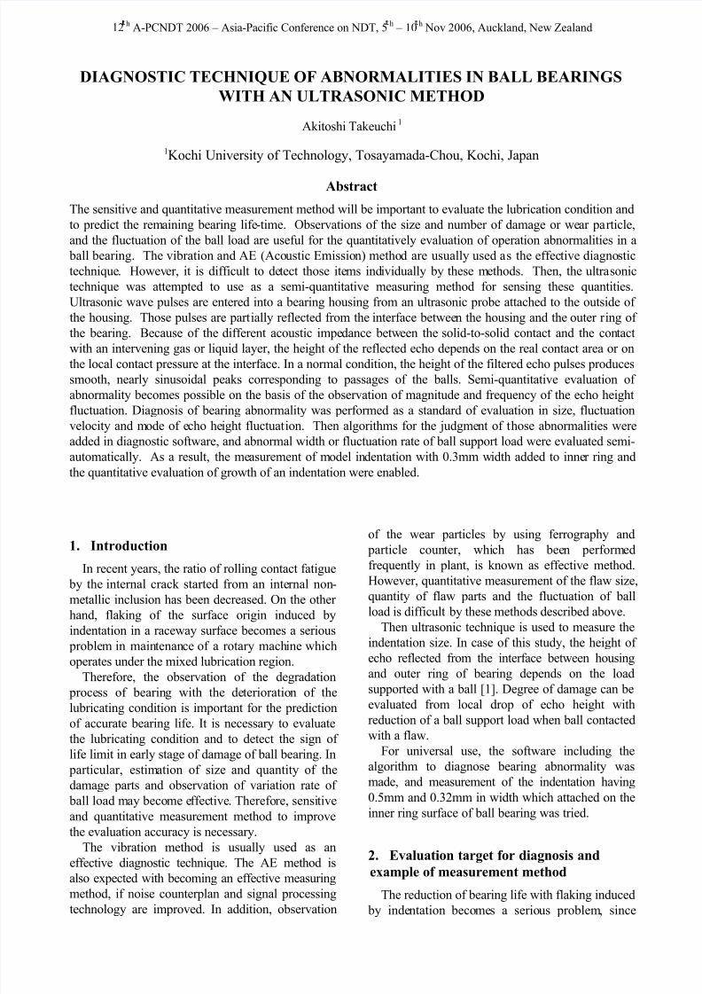
Figure 1: Diagnosis items for indentation
Fig.1 shows the evaluation items which becomes
important for the improvement of prediction
accuracy of operation conditions in ball bearing
with indentation on a surface of raceway. As the
flaw on a surface is able to progress to severe
flaking, in-situ and quantitative evaluation of the
indentation length and the quantity of damage part becomes important. In addition, the fluctuation of
the ball load seems to influence a life of bearing, too.
Therefore, it is necessary to evaluate it
quantitatively. Father more, information of the wear
particle which exist between orbital plane and
rolling element is also important, because the
intervened wear particle affect the formation of
indentation. Then, sensitive and quantitative
measurement methods for sensing those items are
necessary.
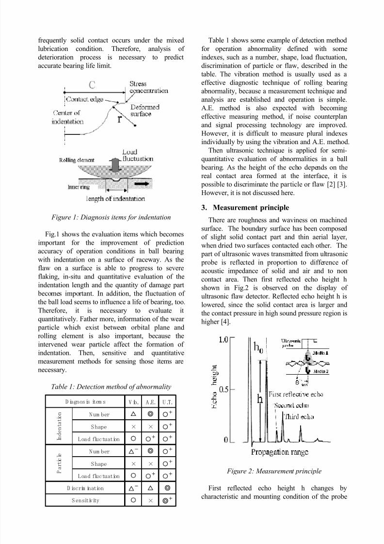
Table 1: Detection method of abnormality
Table 1 shows some example of detection method
for operation abnormality defined with some
indexes, such as a number, shape, load fluctuation,
discrimination of particle or flaw, described in the
table. The vibration method is usually used as a
effective diagnostic technique of rolling bearing
abnormality, because a measurement technique and
analysis are established and operation is simple.
A.E. method is also expected with becoming
effective measuring method, if noise counterplan
and signal processing technology are improved.
However, it is difficult to measure plural indexes
individually by using the vibration and A.E. method.
Then ultrasonic technique is applied for semi-
quantitative evaluation of abnormalities in a ball
bearing. As the height of the echo depends on the
real contact area formed at the interface, it is
possible to discriminate the particle or flaw [2] [3].
However, it is not discussed here.
3. Measurement principle
There are roughness and waviness on machined
surface. The boundary surface has been composed
of slight solid contact part and thin aerial layer,
when dried two surfaces contacted each other. The
part of ultrasonic waves transmitted from ultrasonic
probe is reflected in proportion to difference of
acoustic impedance of solid and air and to non
contact area. Then first reflected echo height h
shown in Fig.2 is observed on the display ofultrasonic flaw detector. Reflected echo height h is
lowered, since the solid contact area is larger and
the contact pressure in high sound pressure region is
higher [4].
Figure 2: Measurement principle
First reflected echo height h changes by
characteristic and mounting condition of the probe
V ib. A .E. U .T.
Num ber
"
#
Shape × ×"
#
Load fluctuation "
"
#
"
#
Num ber
$
"
#
Shape × ×"
#
Load fluctuation" "
#
"
#
$
" ×
#Sensitivity
Diagnosis item s
I n d e n t a t i o n
P
a r t i c l e
D iscrim ination
7/23/2019 DIAGNOSTIC TECHNIQUE OF ABNORMALITIES IN BALL BEARINGS WITH AN ULTRASONIC METHOD
http://slidepdf.com/reader/full/diagnostic-technique-of-abnormalities-in-ball-bearings-with-an-ultrasonic-method 3/6
and effect of diffusion and scattering of the acoustic
wave in propagating route. For excluding these
effects, the contact condition is evaluated by the
value (h/h0) which was standardized by echo height
h0 in the condition that two surfaces were perfectly
separated [5] [6].
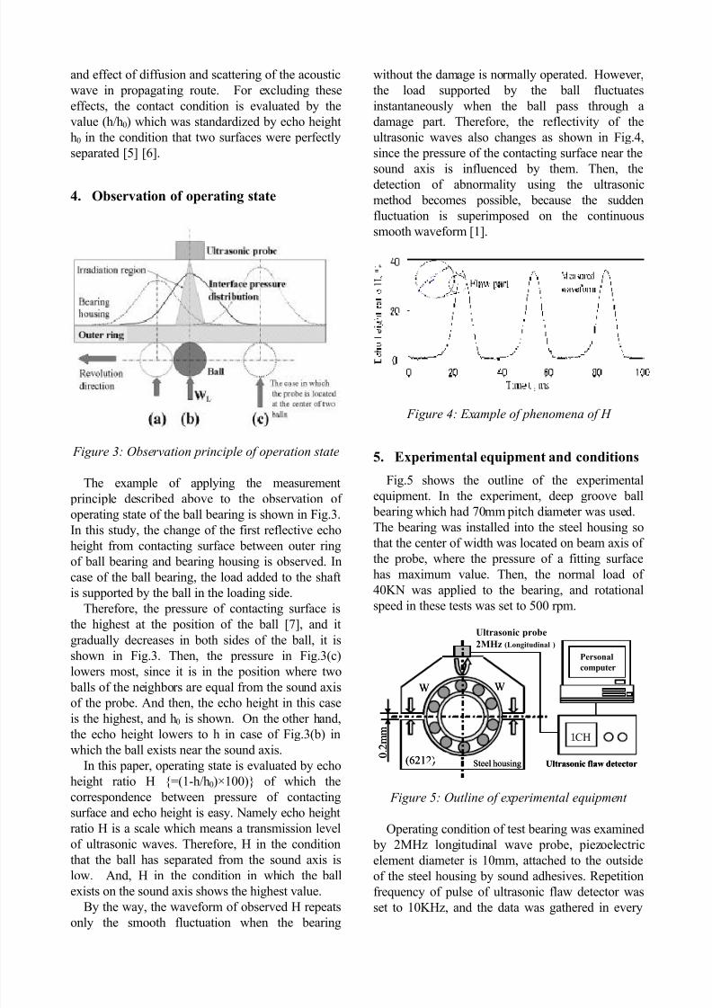
4. Observation of operating state
Figure 3: Observation principle of operation state
The example of applying the measurement
principle described above to the observation of
operating state of the ball bearing is shown in Fig.3.
In this study, the change of the first reflective echoheight from contacting surface between outer ring
of ball bearing and bearing housing is observed. In
case of the ball bearing, the load added to the shaft
is supported by the ball in the loading side.
Therefore, the pressure of contacting surface is
the highest at the position of the ball [7], and it
gradually decreases in both sides of the ball, it is
shown in Fig.3. Then, the pressure in Fig.3(c)
lowers most, since it is in the position where two
balls of the neighbors are equal from the sound axis
of the probe. And then, the echo height in this caseis the highest, and h0 is shown. On the other hand,
the echo height lowers to h in case of Fig.3(b) in
which the ball exists near the sound axis.
In this paper, operating state is evaluated by echo
height ratio H {=(1-h/h0)×100)} of which the
correspondence between pressure of contacting
surface and echo height is easy. Namely echo height
ratio H is a scale which means a transmission level
of ultrasonic waves. Therefore, H in the condition
that the ball has separated from the sound axis is
low. And, H in the condition in which the ball
exists on the sound axis shows the highest value.
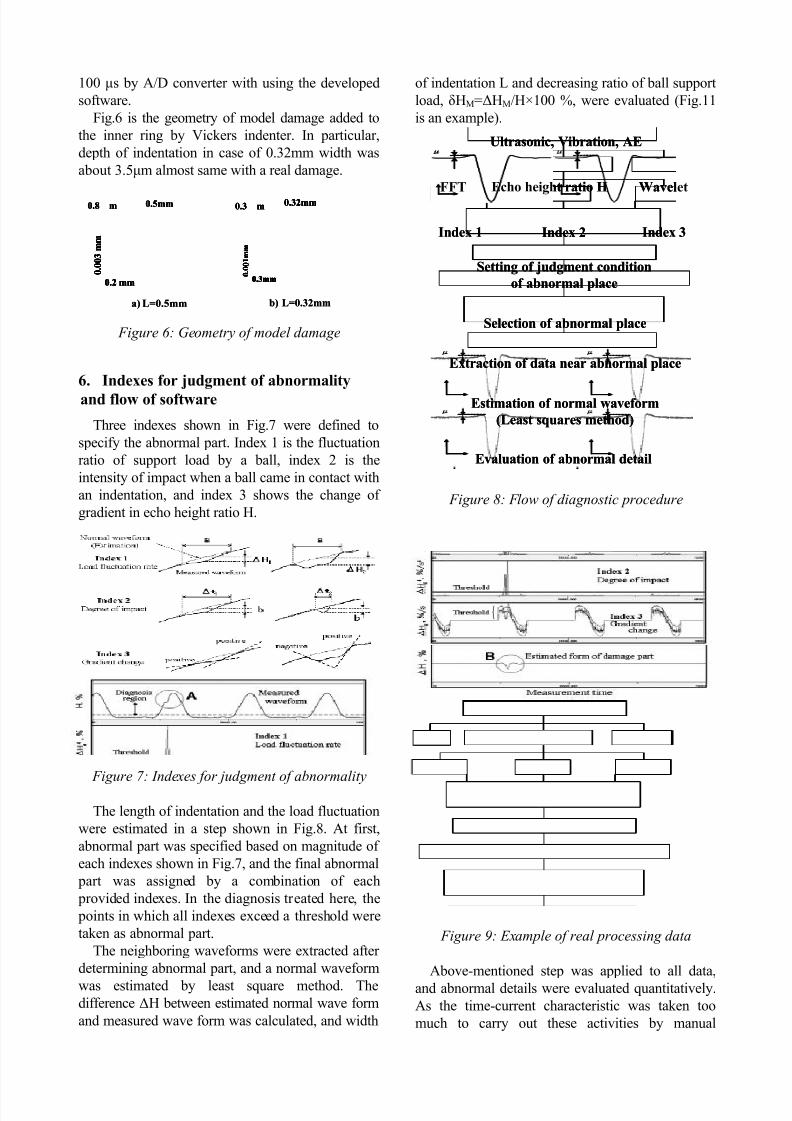
By the way, the waveform of observed H repeats
only the smooth fluctuation when the bearing
without the damage is normally operated. However,
the load supported by the ball fluctuates
instantaneously when the ball pass through a
damage part. Therefore, the reflectivity of the
ultrasonic waves also changes as shown in Fig.4,
since the pressure of the contacting surface near the
sound axis is influenced by them. Then, the
detection of abnormality using the ultrasonic
method becomes possible, because the sudden
fluctuation is superimposed on the continuous
smooth waveform [1].
Figure 4: Example of phenomena of H
5. Experimental equipment and conditions
Fig.5 shows the outline of the experimental
equipment. In the experiment, deep groove ball
bearing which had 70mm pitch diameter was used.
The bearing was installed into the steel housing sothat the center of width was located on beam axis of
the probe, where the pressure of a fitting surface
has maximum value. Then, the normal load of
40KN was applied to the bearing, and rotational
speed in these tests was set to 500 rpm.
Figure 5: Outline of experimental equipment
Operating condition of test bearing was examined
by 2MHz longitudinal wave probe, piezoelectric
element diameter is 10mm, attached to the outside
of the steel housing by sound adhesives. Repetition
frequency of pulse of ultrasonic flaw detector was
set to 10KHz, and the data was gathered in every
0 . 2
m m
(6212)
W W
CH
Steel housing Ultrasonic flaw detector
Ultrasonic probe
2MHz (Longitudinal )
Personal
computer
0 . 2
m m
(6212)
W W
CH
Steel housing Ultrasonic flaw detector
Ultrasonic probe
2MHz (Longitudinal )
Personal
computer
7/23/2019 DIAGNOSTIC TECHNIQUE OF ABNORMALITIES IN BALL BEARINGS WITH AN ULTRASONIC METHOD
http://slidepdf.com/reader/full/diagnostic-technique-of-abnormalities-in-ball-bearings-with-an-ultrasonic-method 4/6
100 s by A/D converter with using the developed
software.
Fig.6 is the geometry of model damage added to
the inner ring by Vickers indenter. In particular,
depth of indentation in case of 0.32mm width was
about 3.5m almost same with a real damage.
Figure 6: Geometry of model damage
6. Indexes for judgment of abnormality
and flow of software
Three indexes shown in Fig.7 were defined to
specify the abnormal part. Index 1 is the fluctuation
ratio of support load by a ball, index 2 is the
intensity of impact when a ball came in contact with
an indentation, and index 3 shows the change of
gradient in echo height ratio H.
Figure 7: Indexes for judgment of abnormality
The length of indentation and the load fluctuation
were estimated in a step shown in Fig.8. At first,
abnormal part was specified based on magnitude of
each indexes shown in Fig.7, and the final abnormal
part was assigned by a combination of each
provided indexes. In the diagnosis treated here, the
points in which all indexes exceed a threshold were
taken as abnormal part.
The neighboring waveforms were extracted after
determining abnormal part, and a normal waveform
was estimated by least square method. Thedifference !H between estimated normal wave form
and measured wave form was calculated, and width
of indentation L and decreasing ratio of ball support
load, "HM=!HM/H×100 %, were evaluated (Fig.11
is an example).
Figure 8: Flow of diagnostic procedure
Figure 9: Example of real processing data
Above-mentioned step was applied to all data,
and abnormal details were evaluated quantitatively.
As the time-current characteristic was taken too
much to carry out these activities by manual
0.2 mm 0 . 0
0 3 m m
0.8%m 0.5mm 0.32mm0.3%m
0 . 0
0 1 m m
0.3mm
a) L=0.5mm b) L=0.32mm
0.2 mm 0 . 0
0 3 m m
0.8%m 0.5mm 0.32mm0.3%m
0 . 0
0 1 m m
0.3mm0.2 mm 0 . 0
0 3 m m
0.2 mm 0 . 0
0 3 m m
0.8%m 0.5mm 0.32mm0.3%m
0 . 0
0 1 m m
0.3mm
0.32mm0.3%m
0 . 0
0 1 m m
0.3mm 0 . 0
0 1 m m
0.3mm
a) L=0.5mm b) L=0.32mm
Ultrasonic, Vibration, AE
FFT Echo height ratio H Wavelet
Index 1 Index 3Index 2
Setting of judgment condition
of abnormal place
Selection of abnormal place
Extraction of data near abnormal place
Estimation of normal waveform
(Least squares method)
Evaluation of abnormal detail
Ultrasonic, Vibration, AE
FFT Echo height ratio H Wavelet
Index 1 Index 3Index 2
Setting of judgment condition
of abnormal place
Selection of abnormal place
Extraction of data near abnormal place
Estimation of normal waveform
(Least squares method)
Evaluation of abnormal detail
7/23/2019 DIAGNOSTIC TECHNIQUE OF ABNORMALITIES IN BALL BEARINGS WITH AN ULTRASONIC METHOD
http://slidepdf.com/reader/full/diagnostic-technique-of-abnormalities-in-ball-bearings-with-an-ultrasonic-method 5/6
operation, algorithm for the judgment of
abnormalities was added in diagnostic software.
However, there was little data of the fatigue test
evaluated by this software, and a correct threshold
with each index could not be determined
automatically. Then each threshold was set low, and
candidate of abnormal parts were elected by
software, and data of the neighborhood were
extracted automatically, and abnormal parts were
decided by visual inspection. Therefore, it was
semiautomatic abnormal diagnostic method, but a
diagnosis time was able to be considerably
shortened by automatic detection of the candidate of
abnormal parts.
An example of real processing data is shown in
Fig. 9. In the region where an echo height ratio was
low, accurate evaluation of the damage was difficult
because a ball locates at the outside of ultrasonic
irradiation region. Then the diagnosis was performed only in the region where the echo height
ratio H exceeded a threshold as shown in the upper
stage of Fig.9. In this example, obtained results
were almost same with index 1 and index 2, and the
gradient of H in index 3 was also reduced suddenly
at the same point. Therefore, the points in which
all of these indexes exceeded the threshold were
identified as abnormal points, and data of H in
region including the neighborhood was extracted.
On the other hand, normal waveform was
estimated by using the least square method whichtreated the echo height data except the data in
abnormal region. The difference between those
waveforms is shown at lower stage of Fig.9, and the
detail is in Fig.10.
Figure 10: Evaluation example of detail of damage
7. Evaluation of indentation width and
decreasing ratio of ball support load
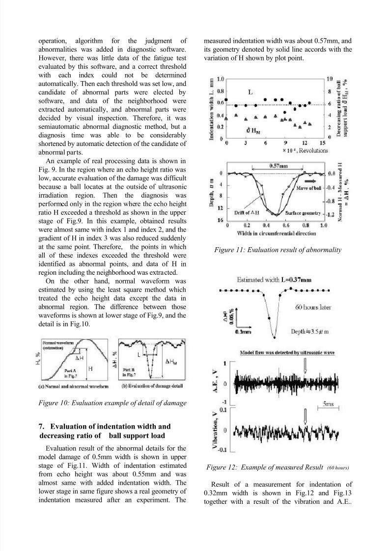
Evaluation result of the abnormal details for the
model damage of 0.5mm width is shown in upper
stage of Fig.11. Width of indentation estimated
from echo height was about 0.55mm and was
almost same with added indentation width. Thelower stage in same figure shows a real geometry of
indentation measured after an experiment. The
measured indentation width was about 0.57mm, and
its geometry denoted by solid line accords with the
variation of H shown by plot point.
Figure 11: Evaluation result of abnormality
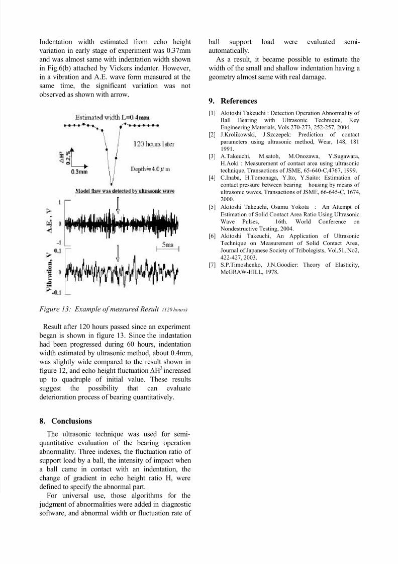
Figure 12: Example of measured Result (60 hours)
Result of a measurement for indentation of0.32mm width is shown in Fig.12 and Fig.13
together with a result of the vibration and A.E..
7/23/2019 DIAGNOSTIC TECHNIQUE OF ABNORMALITIES IN BALL BEARINGS WITH AN ULTRASONIC METHOD
http://slidepdf.com/reader/full/diagnostic-technique-of-abnormalities-in-ball-bearings-with-an-ultrasonic-method 6/6
Indentation width estimated from echo height
variation in early stage of experiment was 0.37mm
and was almost same with indentation width shown
in Fig.6(b) attached by Vickers indenter. However,
in a vibration and A.E. wave form measured at the
same time, the significant variation was not
observed as shown with arrow.
Figure 13: Example of measured Result (120 hours)
Result after 120 hours passed since an experiment
began is shown in figure 13. Since the indentation
had been progressed during 60 hours, indentation
width estimated by ultrasonic method, about 0.4mm,
was slightly wide compared to the result shown in
figure 12, and echo height fluctuation !H3 increased
up to quadruple of initial value. These results
suggest the possibility that can evaluate
deterioration process of bearing quantitatively.
8. Conclusions
The ultrasonic technique was used for semi-
quantitative evaluation of the bearing operation
abnormality. Three indexes, the fluctuation ratio of
support load by a ball, the intensity of impact when
a ball came in contact with an indentation, the
change of gradient in echo height ratio H, were
defined to specify the abnormal part.
For universal use, those algorithms for the judgment of abnormalities were added in diagnostic
software, and abnormal width or fluctuation rate of
ball support load were evaluated semi-
automatically.
As a result, it became possible to estimate the
width of the small and shallow indentation having a
geometry almost same with real damage.
9.
References
[1] Akitoshi Takeuchi : Detection Operation Abnormality of
Ball Bearing with Ultrasonic Technique, Key
Engineering Materials, Vols.270-273, 252-257, 2004.
[2]
J.Krolikowski, J.Szczepek: Prediction of contact
parameters using ultrasonic method, Wear, 148, 181
1991.
[3]
A.Takeuchi, M.satoh, M.Onozawa, Y.Sugawara,
H.Aoki : Measurement of contact area using ultrasonic
technique, Transactions of JSME, 65-640-C,4767, 1999.
[4]
C.Inaba, H.Tomonaga, Y.Ito, Y.Saito: Estimation of
contact pressure between bearing housing by means of
ultrasonic waves, Transactions of JSME, 66-645-C, 1674,
2000.
[5]
Akitoshi Takeuchi, Osamu Yokota ! An Attempt of
Estimation of Solid Contact Area Ratio Using Ultrasonic
Wave Pulses, 16th. World Conference on
Nondestructive Testing, 2004.
[6]
Akitoshi Takeuchi, An Application of Ultrasonic
Technique on Measurement of Solid Contact Area,
Journal of Japanese Society of Tribologists, Vol.51, No2,
422-427, 2003.
[7]
S.P.Timoshenko, J.N.Goodier: Theory of Elasticity,
McGRAW-HILL, 1978.