devicenet fanuc manual
TRANSCRIPT

FANUC Robotics SYSTEM R -J3iB Controller DeviceNet Setup and
Operations Manual Copyright © 2002 FANUC Robotics North America, Inc.
MAROIBDNT20501E REV. A
Applies to software version 6.22 and higher.
About This Manual
Copyrights and Trademarks
This new publication contains proprietary information of FANUC Robotics North America, Inc. furnished for customer use only. No other uses are authorized without the express written permission of FANUC Robotics North America, Inc.
FANUC Robotics North America, Inc 3900 W. Hamlin Road Rochester Hills, Michigan 48309-3253
FANUC Robotics North America, Inc. The descriptions and specifications contained in this manual were in effect at the time this manual was approved. FANUC Robotics North America, Inc, hereinafter referred to as FANUC Robotics, reserves the right to discontinue models at any time or to change specifications or design without notice and without incurring obligations.
FANUC Robotics manuals present descriptions, specifications, drawings, schematics, bills of material, parts, connections and/or procedures for installing, disassembling, connecting, operating and programming FANUC Robotics' products and/or systems. Such systems consist of robots, extended axes, robot controllers, application software, the KAREL® programming language, INSIGHT® vision equipment, and special tools.
FANUC Robotics recommends that only persons who have been trained in one or more approved FANUC Robotics Training Course(s) be permitted to install, operate, use, perform procedures on, repair, and/or maintain FANUC Robotics' products and/or systems and their respective components. Approved training necessitates that the courses selected be relevant to the type of system installed and application performed at the customer site.
Warning
This equipment generates, uses, and can radiate radio frequency energy and if not installed and used in accordance with the instruction manual, may cause interference to radio communications. As temporarily permitted by regulation, it has not been tested for compliance with the limits for Class A computing devices pursuant to subpart J of Part 15 of FCC Rules, which are designed to provide reasonable protection against such interference. Operation of the equipment in a residential area is likely to cause interference, in which case the user, at his own expense, will be required to take whatever measure may be required to correct the interference.
No se puede mostrar la imagen. Puede que su equipo no tenga suficiente memoria para abrir la imagen o que ésta esté dañada. Reinicie el equipo y, a continuación, abra el archivo de nuevo. Si sigue apareciendo la x roja, puede que tenga que borrar la imagen e insertarla de nuevo.

FANUC Robotics conducts courses on its systems and products on a regularly scheduled basis at its headquarters in Rochester Hills, Michigan. For additional information contact
FANUC Robotics North America, Inc Training Department 3900 W. Hamlin Road Rochester Hills, Michigan 48309-3253
www.fanucrobotics.com
For customer assistance, including Technical Support, Service, Parts & Part Repair, and Marketing Requests, contact the Customer Resource Center, 24 hours a day, at 1-800-47-ROBOT (1-800-477-6268). International customers should call 011-1-248-377-7159.
Send your comments and suggestions about this manual to: <[email protected] >
The information illustrated or contained herein is not to be reproduced, copied, translated into another language, or transmitted in whole or in part in any way without the prior written consent of FANUC Robotics North America, Inc.
AccuStat®, ArcTool®, KAREL®, PaintTool®, PalletTool ®, SOCKETS®, SpotTool®, SpotWorks®, and TorchMate® are Registere d Trademarks of FANUC Robotics.
FANUC Robotics reserves all proprietary rights, including but not limited to trademark and trade name rights, in the following names:
AccuAir™, AccuCal™, AccuChop™, AccuFlow™, AccuPath™, AccuSeal™, ARC Mate™, ARC Mate Sr.™, ARC Mate System 1™, ARC Mate System 2™, ARC Mate System 3™, ARC Mate System 4™, ARC Mate System 5™, ARCWorks Pro™, AssistTool™, AutoNormal™, AutoTCP™, BellTool™, BODYWorks™, Cal Mate™, Cell Finder™, Center Finder™, Clean Wall™, CollisionGuard™, DispenseTool™, F-100™, F-200i™, FabTool™, FANUC LASER DRILL™, Flexibell™, FlexTool™, HandlingTool™, HandlingWorks™, INSIGHT™, INSIGHT II™, IntelliTrak™, Integrated Process Solution™, Intelligent Assist Device™, IPC -Integrated Pump Control™, IPD Integral Pneumatic Dispenser™, ISA Integral Servo Applicator™, ISD Integral Servo Dispenser™, Laser Mate System 3™, Laser Mate System 4™, LaserPro™, LaserTool™, LR Tool™, MIG Eye™, MotionParts™, NoBots™, Paint Stick™, PaintPro™, PaintTool 100™, PAINTWorks™, PAINTWorks II™, PAINTWorks III™, PalletMate™, PalletMate PC™, PalletTool PC™, PayloadID™, RecipTool™, RemovalTool™, Robo Chop™, Robo Spray™, S-420i™, S-430i™, ShapeGen™, SoftFloat™, SOFT PARTS™, SpotTool+™, SR Mate™, SR ShotTool™, SureWeld™, SYSTEM R-J2 Controller™, SYSTEM R-J3 Controller™, SYSTEM R-J3i MODEL B Controller™, TCP Mate™, TorchMate™, TurboMove™, visLOC™, visPRO-3D™, visTRAC™, WebServer™, WebTP™, and YagTool™.
Patents
One for more of the following U.S. patents might be related to the FANUC Robotics products described in this manual.
3,906,323 4,274,802 4,289,441 4,299,529 4,336,926 4,348,623 4,359,815 4,366,423 4,374,349 4,396,973 4,396,975 4,396,987 4,406,576 4,415,965 4,416,577 4,430,923 4,431,366 4,458,188 4,462,748 4,465,424 4,466,769 4,475,160 4,479,673 4,479,754 4,481,568 4,482,289 4,482,968 4,484,855 4,488,242 4,488,746 4,489,821 4,492,301 4,495,453 4,502,830 4,504,771 4,530,062 4,530,636 4,538,639 4,540,212 4,542,471 4,543,639 4,544,971 4,549,276 4,549,846 4,552,506 4,554,497 4,556,361 4,557,660 4,562,551 4,575,666 4,576,537 4,591,944 4,603,286 4,626,756 4,628,778 4,630,567 4,637,773 4,638,143 4,639,878 4,647,753 4,647,827 4,650,952 4,652,203 4,653,975 4,659,279 4,659,280 4,663,730 4,672,287 4,679,297 4,680,518 4,697,979 4,698,777 4,700,118 4,700,314 4,701,686 4,702,665 4,706,000 4,706,001 4,706,003 4,707,647 4,708,175 4,708,580 4,712,972 4,723,207 4,727,303 4,728,247 4,728,872 4,732,526 4,742,207 4,742,611 4,750,858 4,753,128 4,754,392 4,771,222 4,773,523 4,773,813 4,774,674 4,775,787 4,776,247 4,777,783 4,780,045 4,780,703 4,782,713 4,785,155 4,796,005 4,805,477 4,807,486 4,812,836 4,813,844 4,815,011 4,815,190 4,816,728 4,816,733 4,816,734 4,827,203 4,827,782 4,828,094 4,829,454 4,829,840 4,831,235 4,835,362 4,836,048 4,837,487 4,842,474 4,851,754 4,852,024 4,852,114 4,855,657 4,857,700 4,859,139 4,859,845 4,866,238 4,873,476 4,877,973 4,892,457 4,892,992 4,894,594 4,894,596 4,894,908 4,899,095 4,902,362 4,903,539 4,904,911 4,904,915 4,906,121 4,906,814 4,907,467 4,908,559 4,908,734 4,908,738 4,916,375 4,916,636 4,920,248 4,922,436 4,931,617 4,931,711 4,934,504 4,942,539 4,943,759 4,953,992 4,956,594 4,956,765 4,965,500 4,967,125 4,969,109 4,969,722 4,969,795 4,970,370 4,970,448 4,972,080 4,972,735 4,973,895 4,974,229 4,975,920 4,979,127 4,979,128 4,984,175 4,984,745 4,988,934 4,990,729 5,004,968 5,006,035 5,008,832 5,008,834 5,012,173 5,013,988 5,034,618 5,051,676 5,055,754 5,057,756 5,057,995 5,060,533 5,063,281 5,063,295 5,065,337 5,066,847 5,066,902 5,075,534 5,085,619 5,093,552 5,094,311 5,099,707 5,105,136 5,107,716 5,111,019 5,111,709 5,115,690 5,192,595 5,221,047 5,238,029 5,239,739 5,272,805 5,286,160 5,289,947 5,293,107 5,293,911 5,313,854 5,316,217 5,331,264 5,367,944 5,373,221 5,421,218 5,423,648 5,434,489 5,644,898 5670202 5,696,687 5,737,218 5,823,389 5853027 5,887,800 5,941,679 5,959,425 5,987,726 6,059,092 6,064,168 6,070,109 6,082,797 6,086,294 6,122,062 6,147,323 6,193,621 6,204,620 6,243,621 6,253,799 6,285,920 6,313,595 6,325,302 6,345,818 6,360,142 6,378,190 6,385,508
VersaBell, ServoBell and SpeedDock Patents Pending.
Conventions
This manual includes information essential to the safety of personnel, equipment, software, and data. This information is indicated by headings and boxes in the text.
Warning
Information appearing under WARNING concerns the protection of personnel. It is boxed and in bold type to set it apart from other text.
Caution
Information appearing under CAUTION concerns the protection of equipment, software, and data. It is boxed to set it apart from other text.
Note
Information appearing next to NOTE concerns related information or useful hints.
Safety
FANUC Robotics is not and does not represent itself as an expert in safety systems, safety equipment, or the specific safety aspects of your company and/or its work force. It is the responsibility of the owner, employer, or user to take all necessary steps to guarantee the safety of all personnel in the workplace.
The appropriate level of safety for your application and installation can best be determined by safety system professionals. FANUC Robotics therefore, recommends that each customer consult with such professionals in order to provide a workplace that allows for the safe application, use, and operation of FANUC Robotic systems.
According to the industry standard ANSI/RIA R15-06, the owner or user is advised to consult the standards to ensure compliance with its requests for Robotics System design, usability, operation, maintenance, and service. Additionally, as the owner, employer, or user of a robotic system, it is your responsibility to arrange for the training of the operator of a robot system to recognize and respond to known hazards associated with your robotic system and to be aware of the recommended operating procedures for your particular application and robot installation.
FANUC Robotics therefore, recommends that all personnel who intend to operate, program, repair, or otherwise use the robotics system be trained in an approved FANUC Robotics training course and become familiar with the proper operation of the system. Persons responsible for programming the system-including the design, implementation, and debugging of application programs-must be familiar with the recommended programming procedures for your application and robot installation.
No se puede mostrar la imagen. Puede que su equipo no tenga suficiente memoria para abrir la imagen o que ésta esté dañada. Reinicie el equipo y, a continuación, abra el archivo de nuevo. Si sigue apareciendo la x roja, puede que tenga que borrar la imagen e insertarla de nuevo.
No se puede mostrar la imagen. Puede que su equipo no tenga suficiente memoria para abrir la imagen o que ésta esté dañada. Reinicie el equipo y, a continuación, abra el archivo de nuevo. Si
sigue apareciendo la x roja, puede que tenga que borrar la imagen e insertarla de nuevo.
The following guidelines are provided to emphasize the importance of safety in the workplace.
CONSIDERING SAFETY FOR YOUR ROBOT INSTALLATION
Safety is essential whenever robots are used. Keep in mind the following factors with regard to safety:
• The safety of people and equipment • Use of safety enhancing devices • Techniques for safe teaching and manual operation of the robot(s) • Techniques for safe automatic operation of the robot(s) • Regular scheduled inspection of the robot and workcell • Proper maintenance of the robot
Keeping People and Equipment Safe
The safety of people is always of primary importance in any situation. However, equipment must be kept safe, too. When prioritizing how to apply safety to your robotic system, consider the following:
• People • External devices • Robot(s) • Tooling • Workpiece
Using Safety Enhancing Devices
Always give appropriate attention to the work area that surrounds the robot. The safety of the work area can be enhanced by the installation of some or all of the following devices:
• Safety fences, barriers, or chains • Light curtains • Interlocks • Pressure mats • Floor markings • Warning lights • Mechanical stops • EMERGENCY STOP buttons • DEADMAN switches
Setting Up a Safe Workcell
A safe workcell is essential to protect people and equipment. Observe the following guidelines to ensure that the workcell is set up safely. These suggestions are intended to supplement and not replace existing federal, state, and local laws, regulations, and guidelines that pertain to safety.
• Sponsor your personnel for training in approved FANUC Robotics training course(s) related to your application. Never permit untrained personnel to operate the robots.
• Install a lockout device that uses an access code to prevent unauthorized persons from operating the robot.
• Use anti-tie-down logic to prevent the operator from bypassing safety measures.
• Arrange the workcell so the operator faces the workcell and can see what is going on inside the cell.
• Clearly identify the work envelope of each robot in the system with floor markings, signs, and special barriers. The work envelope is the area defined by the maximum motion range of the robot, including any tooling attached to the wrist flange that extend this range.
• Position all controllers outside the robot work envelope. • Never rely on software as the primary safety element. • Mount an adequate number of EMERGENCY STOP buttons or switches
within easy reach of the operator and at critical points inside and around the outside of the workcell.
• Install flashing lights and/or audible warning devices that activate whenever the robot is operating, that is, whenever power is applied to the servo drive system. Audible warning devices shall exceed the ambient noise level at the end-use application.
• Wherever possible, install safety fences to protect against unauthorized entry by personnel into the work envelope.
• Install special guarding that prevents the operator from reaching into restricted areas of the work envelope.
• Use interlocks. • Use presence or proximity sensing devices such as light curtains, mats,
and capacitance and vision systems to enhance safety. • Periodically check the safety joints or safety clutches that can be
optionally installed between the robot wrist flange and tooling. If the tooling strikes an object, these devices dislodge, remove power from the system, and help to minimize damage to the tooling and robot.
• Make sure all external devices are properly filtered, grounded, shielded, and suppressed to prevent hazardous motion due to the effects of electro-magnetic interference (EMI), radio frequency interference (RFI), and electro-static discharge (ESD).
• Make provisions for power lockout/tagout at the controller. • Eliminate pinch points . Pinch points are areas where personnel could
get trapped between a moving robot and other equipment. • Provide enough room inside the workcell to permit personnel to teach the
robot and perform maintenance safely. • Program the robot to load and unload material safely. • If high voltage electrostatics are present, be sure to provide appropriate
interlocks, warning, and beacons. • If materials are being applied at dangerously high pressure, provide
electrical interlocks for lockout of material flow and pressure.
Staying Safe While Teaching or Manually Operating t he Robot
Advise all personnel who must teach the robot or otherwise manually operate the robot to observe the following rules:
• Never wear watches, rings, neckties, scarves, or loose clothing that could get caught in moving machinery.
• Know whether or not you are using an intrinsically safe teach pendant if you are working in a hazardous environment.
• Before teaching, visually inspect the robot and work envelope to make sure that no potentially hazardous conditions exist. The work envelope is the area defined by the maximum motion range of the robot. These include tooling attached to the wrist flange that extends this range.
• The area near the robot must be clean and free of oil, water, or debris. Immediately report unsafe working conditions to the supervisor or safety department.
• FANUC Robotics recommends that no one enter the work envelope of a robot that is on, except for robot teaching operations. However, if you must enter the work envelope, be sure all safeguards are in place, check the teach pendant DEADMAN switch for proper operation, and place the robot in teach mode. Take the teach pendant with you, turn it on, and be prepared to release the DEADMAN switch. Only the person with the teach pendant should be in the work envelope.
Warning
Never bypass, strap, or otherwise deactivate a safety device, such as a limit switch, for any operational convenience. Deactivating a safety device is known to have resulted in serious injury and death.
• • Know the path that can be used to escape from a moving robot; make
sure the escape path is never blocked. • Isolate the robot from all remote control signals that can cause motion
while data is being taught. • Test any program being run for the first time in the following manner:
Warning
Stay outside the robot work envelope whenever a program is being run. Failure to do so can result in injury.
• o Using a low motion speed, single step the program for at least one
full cycle. o Using a low motion speed, test run the program continuously for at
least one full cycle. o Using the programmed speed, test run the program continuously
for at least one full cycle.
No se puede mostrar la imagen. Puede que su equipo no tenga suficiente memoria para abrir la imagen o que ésta esté dañada. Reinicie el equipo y, a continuación, abra el archivo de nuevo. Si sigue apareciendo la x roja, puede que tenga que borrar la imagen e insertarla de nuevo.
No se puede mostrar la imagen. Puede que su equipo no tenga suficiente memoria para abrir la imagen o que ésta esté dañada. Reinicie el equipo y, a continuación, abra el archivo de nuevo. Si sigue apareciendo la x roja, puede que tenga que borrar la imagen e insertarla de nuevo.
• Make sure all personnel are outside the work envelope before running production.
Staying Safe During Automatic Operation
Advise all personnel who operate the robot during production to observe the following rules:
• Make sure all safety provisions are present and active. • Know the entire workcell area. The workcell includes the robot and its
work envelope, plus the area occupied by all external devices and other equipment with which the robot interacts.
• Understand the complete task the robot is programmed to perform before initiating automatic operation.
• Make sure all personnel are outside the work envelope before operating the robot.
• Never enter or allow others to enter the work envelope during automatic operation of the robot.
• Know the location and status of all switches, sensors, and control signals that could cause the robot to move.
• Know where the EMERGENCY STOP buttons are located on both the robot control and external control devices. Be prepared to press these buttons in an emergency.
• Never assume that a program is complete if the robot is not moving. The robot could be waiting for an input signal that will permit it to continue activity.
• If the robot is running in a pattern, do not assume it will continue to run in the same pattern.
• Never try to stop the robot, or break its motion, with your body. The only way to stop robot motion immediately is to press an EMERGENCY STOP button located on the controller panel, teach pendant, or emergency stop stations around the workcell.
Staying Safe During Inspection
When inspecting the robot, be sure to
• Turn off power at the controller. • Lock out and tag out the power source at the controller according to the
policies of your plant. • Turn off the compressed air source and relieve the air pressure. • If robot motion is not needed for inspecting the electrical circuits, press
the EMERGENCY STOP button on the operator panel. • Never wear watches, rings, neckties, scarves, or loose clothing that
could get caught in moving machinery. • If power is needed to check the robot motion or electrical circuits, be
prepared to press the EMERGENCY STOP button, in an emergency. • Be aware that when you remove a servomotor or brake, the associated
robot arm will fall if it is not supported or resting on a hard stop. Support the arm on a solid support before you release the brake.
Staying Safe During Maintenance
When performing maintenance on your robot system, observe the following rules:
• Never enter the work envelope while the robot or a program is in operation.
• Before entering the work envelope, visually inspect the workcell to make sure no potentially hazardous conditions exist.
• Never wear watches, rings, neckties, scarves, or loose clothing that could get caught in moving machinery.
• Consider all or any overlapping work envelopes of adjoining robots when standing in a work envelope.
• Test the teach pendant for proper operation before entering the work envelope.
• If it is necessary for you to enter the robot work envelope while power is turned on, you must be sure that you are in control of the robot. Be sure to take the teach pendant with you, press the DEADMAN switch, and turn the teach pendant on. Be prepared to release the DEADMAN switch to turn off servo power to the robot immediately.
• Whenever possible, perform maintenance with the power turned off. Before you open the controller front panel or enter the work envelope, turn off and lock out the 3-phase power source at the controller.
• Be aware that an applicator bell cup can continue to spin at a very high speed even if the robot is idle. Use protective gloves or disable bearing air and turbine air before servicing these items.
• Be aware that when you remove a servomotor or brake, the associated robot arm will fall if it is not supported or resting on a hard stop. Support the arm on a solid support before you release the brake.
Warning
Lethal voltage is present in the controller WHENEVER IT IS CONNECTED to a power source. Be extremely careful to avoid electrical shock.HIGH VOLTAGE IS PRESENT at the input side whenever the controller is connected to a power source. Turning the disconnect or circuit breaker to the OFF position removes power from the output side of the device only.
• • Release or block all stored energy. Before working on the pneumatic
system, shut off the system air supply and purge the air lines. • Isolate the robot from all remote control signals. If maintenance must be
done when the power is on, make sure the person inside the work envelope has sole control of the robot. The teach pendant must be held by this person.
• Make sure personnel cannot get trapped between the moving robot and other equipment. Know the path that can be used to escape from a moving robot. Make sure the escape route is never blocked.
No se puede mostrar la imagen. Puede que su equipo no tenga suficiente memoria para abrir la imagen o que ésta esté dañada. Reinicie el equipo y, a continuación, abra el archivo de nuevo. Si sigue apareciendo la x roja, puede que tenga que borrar la imagen e insertarla de nuevo.
• Use blocks, mechanical stops, and pins to prevent hazardous movement by the robot. Make sure that such devices do not create pinch points that could trap personnel.
Warning
Do not try to remove any mechanical component from the robot before thoroughly reading and understanding the procedures in the appropriate manual. Doing so can result in serious personal injury and component destruction.
• • Be aware that when you remove a servomotor or brake, the associated
robot arm will fall if it is not supported or resting on a hard stop. Support the arm on a solid support before you release the brake.
• When replacing or installing components, make sure dirt and debris do not enter the system.
• Use only specified parts for replacement. To avoid fires and damage to parts in the controller, never use nonspecified fuses.
• Before restarting a robot, make sure no one is inside the work envelope; be sure that the robot and all external devices are operating normally.
KEEPING MACHINE TOOLS AND EXTERNAL DEVICES SAFE
Certain programming and mechanical measures are useful in keeping the machine tools and other external devices safe. Some of these measures are outlined below. Make sure you know all associated measures for safe use of such devices.
Programming Safety Precautions
Implement the following programming safety measures to prevent damage to machine tools and other external devices.
• Back-check limit switches in the workcell to make sure they do not fail. • Implement “failure routines” in programs that will provide appropriate
robot actions if an external device or another robot in the workcell fails. • Use handshaking protocol to synchronize robot and external device
operations. • Program the robot to check the condition of all external devices during an
operating cycle.
Mechanical Safety Precautions
Implement the following mechanical safety measures to prevent damage to machine tools and other external devices.
• Make sure the workcell is clean and free of oil, water, and debris.
No se puede mostrar la imagen. Puede que su equipo no tenga suficiente memoria para abrir la imagen o que ésta esté dañada. Reinicie el equipo y, a continuación, abra el archivo de nuevo. Si sigue apareciendo la x roja, puede que tenga que borrar la imagen e insertarla de nuevo.
• Use software limits, limit switches, and mechanical hardstops to prevent undesired movement of the robot into the work area of machine tools and external devices.
KEEPING THE ROBOT SAFE
Observe the following operating and programming guidelines to prevent damage to the robot.
Operating Safety Precautions
The following measures are designed to prevent damage to the robot during operation.
• Use a low override speed to increase your control over the robot when jogging the robot.
• Visualize the movement the robot will make before you press the jog keys on the teach pendant.
• Make sure the work envelope is clean and free of oil, water, or debris. • Use circuit breakers to guard against electrical overload.
Programming Safety Precautions
The following safety measures are designed to prevent damage to the robot during programming:
• Establish interference zones to prevent collisions when two or more robots share a work area.
• Make sure that the program ends with the robot near or at the home position.
• Be aware of signals or other operations that could trigger operation of tooling resulting in personal injury or equipment damage.
• In dispensing applications, be aware of all safety guidelines with respect to the dispensing materials.
Note
Any deviation from the methods and safety practices described in this manual must conform to the approved standards of your company. If you have questions, see your supervisor.
•
ADDITIONAL SAFETY CONSIDERATIONS FOR PAINT ROBOT INSTALLATIONS
Process technicians are sometimes required to enter the paint booth, for example, during daily or routine calibration or while teaching new paths to a robot. Maintenance personal also must work inside the paint booth periodically.
Whenever personnel are working inside the paint booth, ventilation equipment must be used. Instruction on the proper use of ventilating equipment usually is provided by the paint shop supervisor.
Although paint booth hazards have been minimized, potential dangers still exist. Therefore, today's highly automated paint booth requires that process and maintenance personnel have full awareness of the system and its capabilities. They must understand the interaction that occurs between the vehicle moving along the conveyor and the robot(s), hood/deck and door opening devices, and high-voltage electrostatic tools.
Paint robots are operated in three modes:
• Teach or manual mode • Automatic mode, including automatic and exercise operation • Diagnostic mode
During both teach and automatic modes, the robots in the paint booth will follow a predetermined pattern of movements. In teach mode, the process technician teaches (programs) paint paths using the teach pendant.
In automatic mode, robot operation is initiated at the System Operator Console (SOC) or Manual Control Panel (MCP), if available, and can be monitored from outside the paint booth. All personnel must remain outside of the booth or in a designated safe area within the booth whenever automatic mode is initiated at the SOC or MCP.
In automatic mode, the robots will execute the path movements they were taught during teach mode, but generally at production speeds.
When process and maintenance personnel run diagnostic routines that require them to remain in the paint booth, they must stay in a designated safe area.
Paint System Safety Features
Process technicians and maintenance personnel must become totally familiar with the equipment and its capabilities. To minimize the risk of injury when working near robots and related equipment, personnel must comply strictly with the procedures in the manuals.
This section provides information about the safety features that are included in the paint system and also explains the way the robot interacts with other equipment in the system.
The paint system includes the following safety features:
• Most paint booths have red warning beacons that illuminate when the robots are armed and ready to paint. Your booth might have other kinds of indicators. Learn what these are.
• Some paint booths have a blue beacon that, when illuminated, indicates that the electrostatic devices are enabled. Your booth might have other kinds of indicators. Learn what these are.
• EMERGENCY STOP buttons are located on the robot controller and teach pendant. Become familiar with the locations of all E-STOP buttons.
• An intrinsically safe teach pendant is used when teaching in hazardous paint atmospheres.
• A DEADMAN switch is located on each teach pendant. When this switch is held in, and the teach pendant is on, power is applied to the robot servo system. If the engaged DEADMAN switch is released during robot operation, power is removed from the servo system, all axis brakes are applied, and the robot comes to an EMERGENCY STOP. Safety interlocks within the system might also E-STOP other robots.
Warning
An EMERGENCY STOP will occur if the DEADMAN switch is released on a bypassed robot.
• • Overtravel by robot axes is prevented by software limits. All of the major
and minor axes are governed by software limits. Limit switches and hardstops also limit travel by the major axes.
• EMERGENCY STOP limit switches and photoelectric eyes might be part of your system. Limit switches, located on the entrance/exit doors of each booth, will EMERGENCY STOP all equipment in the booth if a door is opened while the system is operating in automatic or manual mode. For some systems, signals to these switches are inactive when the switch on the SCC is in teach mode.When present, photoelectric eyes are sometimes used to monitor unauthorized intrusion through the entrance/exit silhouette openings.
• System status is monitored by computer. Severe conditions result in automatic system shutdown.
Staying Safe While Operating the Paint Robot
When you work in or near the paint booth, observe the following rules, in addition to all rules for safe operation that apply to all robot systems.
Warning
Observe all safety rules and guidelines to avoid injury.
Warning
Never bypass, strap, or otherwise deactivate a safety device, such as a limit switch, for any operational convenience. Deactivating a safety device is known to have resulted in serious injury and death.
No se puede mostrar la imagen. Puede que su equipo no tenga
suficiente memoria para abrir la imagen o que ésta esté dañada. Reinicie el equipo y, a continuación, abra el archivo de nuevo. Si sigue apareciendo la x roja, puede que tenga que borrar la imagen e insertarla de nuevo.
No se puede mostrar la imagen. Puede que su equipo no tenga suficiente memoria para abrir la imagen o que ésta esté dañada. Reinicie el equipo y, a continuación, abra el archivo de nuevo. Si sigue apareciendo la x roja, puede que tenga que borrar la imagen e insertarla de nuevo.
No se puede mostrar la imagen. Puede que su equipo no tenga suficiente memoria para abrir la imagen o que ésta esté dañada. Reinicie el equipo y, a continuación, abra el archivo de nuevo. Si sigue apareciendo la x roja, puede que tenga que borrar la imagen e insertarla de nuevo.
• Know the work area of the entire paint station (workcell). • Know the work envelope of the robot and hood/deck and door opening
devices. • Be aware of overlapping work envelopes of adjacent robots. • Know where all red, mushroom-shaped EMERGENCY STOP buttons are
located. • Know the location and status of all switches, sensors, and/or control
signals that might cause the robot, conveyor, and opening devices to move.
• Make sure that the work area near the robot is clean and free of water, oil, and debris. Report unsafe conditions to your supervisor.
• Become familiar with the complete task the robot will perform BEFORE starting automatic mode.
• Make sure all personnel are outside the paint booth before you turn on power to the robot servo system.
• Never enter the work envelope or paint booth before you turn off power to the robot servo system.
• Never enter the work envelope during automatic operation unless a safe area has been designated.
• Never wear watches, rings, neckties, scarves, or loose clothing that could get caught in moving machinery.
• Remove all metallic objects, such as rings, watches, and belts, before entering a booth when the electrostatic devices are enabled.
• Stay out of areas where you might get trapped between a moving robot, conveyor, or opening device and another object.
• Be aware of signals and/or operations that could result in the triggering of guns or bells.
• Be aware of all safety precautions when dispensing of paint is required. • Follow the procedures described in this manual.
Staying Safe While Operating Paint Application Equi pment
When you work with paint application equipment, observe the following rules, in addition to all rules for safe operation that apply to all robot systems.
Warning
When working with electrostatic paint equipment, follow all national and local codes as well as all safety guidelines within your organization. Also reference the following standards: NFPA 33 Standards for Spray Application Using Flammable or Combustible Materials, and NFPA 70 National Electrical Code.
• Grounding : All electrically conductive objects in the spray area must be grounded. This includes the spray booth, robots, conveyors, workstations, part carriers, hooks, paint pressure pots, as well as solvent
No se puede mostrar la imagen. Puede que su equipo no tenga suficiente memoria para abrir la imagen o que ésta esté dañada. Reinicie el equipo y, a continuación, abra el archivo de nuevo. Si sigue apareciendo la x roja, puede que tenga que borrar la imagen e insertarla de nuevo.
containers. Grounding is defined as the object or objects shall be electrically connected to ground with a resistance of not more than 1 megohms.
• High Voltage : High voltage should only be on during actual spray operations. Voltage should be off when the painting process is completed. Never leave high voltage on during a cap cleaning process.
• Avoid any accumulation of combustible vapors or coating matter. • Follow all manufacturer recommended cleaning procedures. • Make sure all interlocks are operational. • No smoking. • Post all warning signs regarding the electrostatic equipment and
operation of electrostatic equipment according to NFPA 33 Standard for Spray Application Using Flammable or Combustible Material.
• Disable all air and paint pressure to bell. • Verify that the lines are not under pressure.
Staying Safe During Maintenance
When you perform maintenance on the painter system, observe the following rules, and all other maintenance safety rules that apply to all robot installations. Only qualified, trained service or maintenance personnel should perform repair work on a robot.
• Paint robots operate in a potentially explosive environment. Use caution when working with electric tools.
• When a maintenance technician is repairing or adjusting a robot, the work area is under the control of that technician. All personnel not participating in the maintenance must stay out of the area.
• For some maintenance procedures, station a second person at the control panel within reach of the EMERGENCY STOP button. This person must understand the robot and associated potential hazards.
• Be sure all covers and inspection plates are in good repair and in place. • Always return the robot to the ``home'' position before you disarm it. • Never use machine power to aid in removing any component from the
robot. • During robot operations, be aware of the robot's movements. Excess
vibration, unusual sounds, and so forth, can alert you to potential problems.
• Whenever possible, turn off the main electrical disconnect before you clean the robot.
• When using vinyl resin observe the following: o Wear eye protection and protective gloves during application and
removal o Adequate ventilation is required. Overexposure could cause
drowsiness or skin and eye irritation. o If there is contact with the skin, wash with water.
• When using paint remover observe the following: o Eye protection, protective rubber gloves, boots, and apron are
required during booth cleaning.
o Adequate ventilation is required. Overexposure could cause drowsiness.
o If there is contact with the skin or eyes, rinse with water for at least 15 minutes. Then, seek medical attention as soon as possible.
1. System Overview
1.1. Overview
The FANUC Robotics DeviceNet Interface is a Controller Area Network (CAN) BUS-based interface that provides a simplified method of connection between industrial actuators and sensors, and an I/O controller. The DeviceNet Interface consists of hardware and software components that allow an R-J3iB controller to connect to one or more DeviceNet networks.
The hardware component consists of a motherboard and, depending on the type of motherboard and your networking requirements, one to four daughterboards. Each board provides an interface to the DeviceNet network. The software component is the FANUC Robotics DeviceNet Interface software, which is installed as an option on the R-J3iB controller.
The DeviceNet Interface offers the following benefits:
• It offers you a better process solution through simplified I/O wiring and a reduction in interface hardware, which results in a communications system that is easier to develop and debug.
• Depending on your hardware configuration, it can offer you the ability to connect to up to four different networks. You can
o Use one network for communications between a host and several controllers in a cell and a second network for all devices local to a single controller.
o Use one network for devices that are located far from the controller and thus require the use of a lower baud rate. Use another network for devices that are closer to the controller and can use a higher baud rate.
• It allows you to use an open, industry-standard, networking protocol to communicate from the robot to a wide array of industrial devices, from simple photoelectric switches and proximity switches to programmable logic controllers (PLCs).
When installed properly, the DeviceNet Interface can be used in combination with any of the following:
• Process I/O boards • Model A I/O modules • Model B I/O modules • Allen-Bradley Remote I/O • Ethernet communications • Profibus DP • ControlNet
To give you a better idea of how to implement the DeviceNet Interface in your system, the following sections provide a physical and functional description of the DeviceNet Interface.
1.2. Hardware Description
The DeviceNet Interface hardware consists of the following components:
• A DeviceNet Interface motherboard, which provides the interface between the R-J3iB controller F-BUS backplane and the PC/104 connection of the daughterboards. There are two kinds of motherboards:
o The full-slot motherboard, shown in Figure 1.1. DeviceNet I/O Interface Board - Full-slot Motherboard with DN Daughterboards , which occupies a full-width slot on the R-J3iB controller backplane
o The wide-mini motherboard, shown in Figure 1.2. DeviceNet I/O Interface Board --Wide-mini Motherboard with DN Daughterboard , which occupies the wide-mini slot of the R-J3iB controller
• One to four DeviceNet daughterboards, which reside on the motherboards. The full-slot motherboard supports up to four daughterboards, while the wide-mini motherboard supports only a single daughterboard. The devices on the networks connected to the daughterboards are configured as racks 81 - 84 for I/O assignment purposes.
• A DeviceNet slave mini F-bus board (board 1 only) •
Note
The R-J3iB controller can support up to two DeviceNet Interface motherboards in a single controller. Only a maximum of four channels of DeviceNet are supported using any combination of single channel and dual channel boards. If a DeviceNet slave board is installed, three additional channels are supported.
Refer to Appendix A. DeviceNet Interface Hardware Details for more information about motherboards and daughterboards. Refer to 2. Hardware and Installation for hardware installation information.
• • Figure 1.1. DeviceNet I/O Interface Board - Full-sl ot Motherboard
with DN Daughterboards
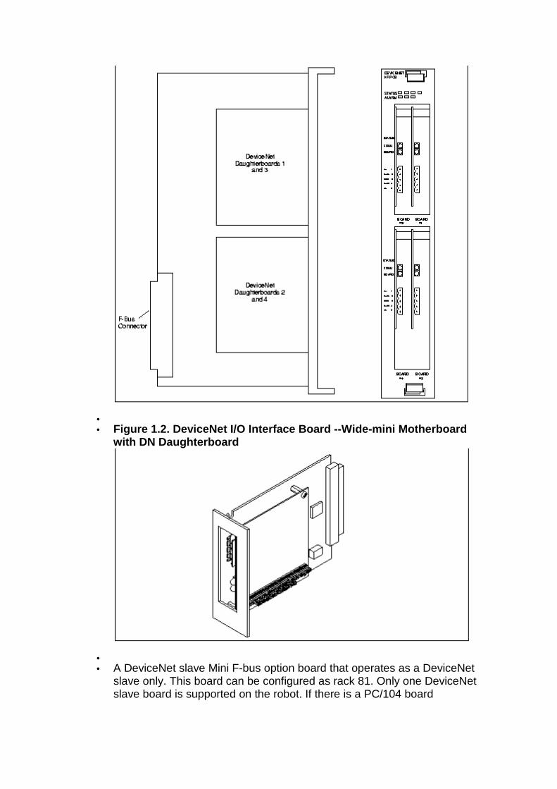
• • Figure 1.2. DeviceNet I/O Interface Board --Wide-mi ni Motherboard
with DN Daughterboard
• • A DeviceNet slave Mini F-bus option board that operates as a DeviceNet
slave only. This board can be configured as rack 81. Only one DeviceNet slave board is supported on the robot. If there is a PC/104 board
configured as rack 81 (Board 1), that board will be ignored and the slave board will be given priority.
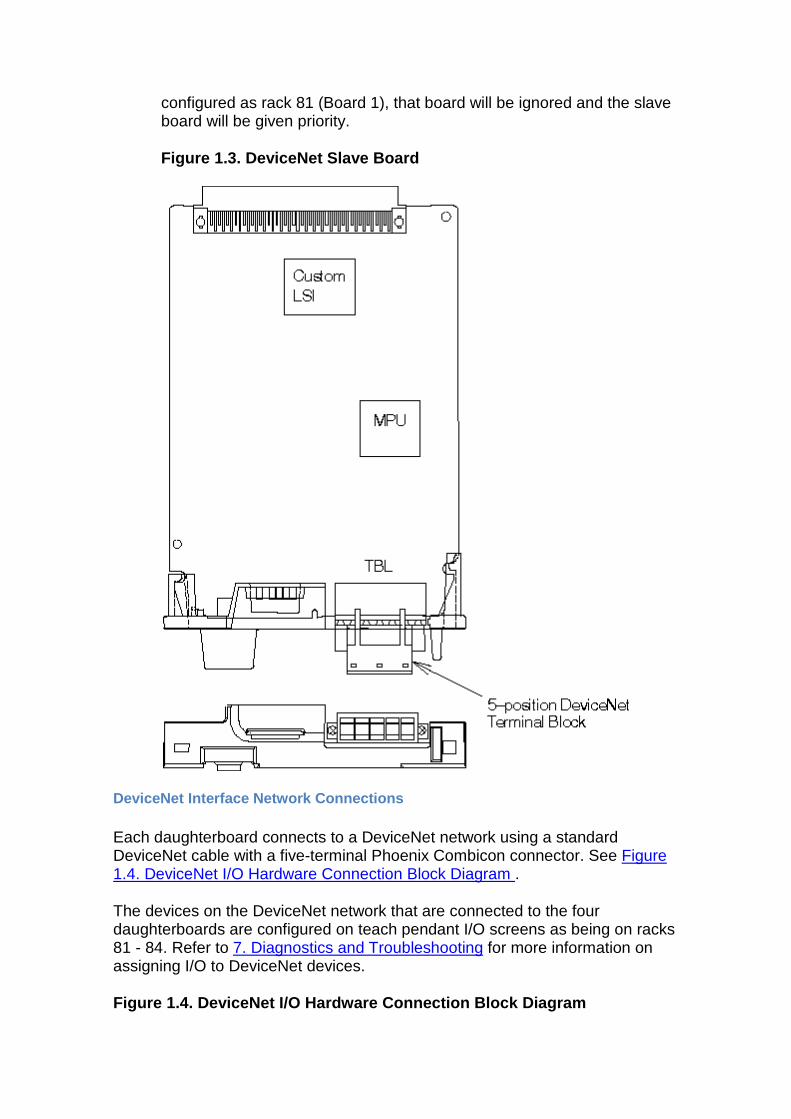
Figure 1.3. DeviceNet Slave Board
DeviceNet Interface Network Connections
Each daughterboard connects to a DeviceNet network using a standard DeviceNet cable with a five-terminal Phoenix Combicon connector. See Figure 1.4. DeviceNet I/O Hardware Connection Block Diagram .
The devices on the DeviceNet network that are connected to the four daughterboards are configured on teach pendant I/O screens as being on racks 81 - 84. Refer to 7. Diagnostics and Troubleshooting for more information on assigning I/O to DeviceNet devices.
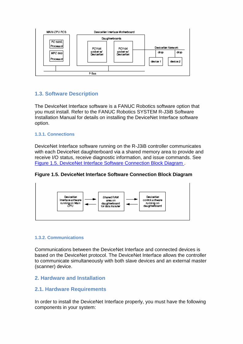
Figure 1.4. DeviceNet I/O Hardware Connection Block Diagram
1.3. Software Description
The DeviceNet Interface software is a FANUC Robotics software option that you must install. Refer to the FANUC Robotics SYSTEM R-J3iB Software Installation Manual for details on installing the DeviceNet Interface software option.
1.3.1. Connections
DeviceNet Interface software running on the R-J3iB controller communicates with each DeviceNet daughterboard via a shared memory area to provide and receive I/O status, receive diagnostic information, and issue commands. See Figure 1.5. DeviceNet Interface Software Connection Block Diagram .
Figure 1.5. DeviceNet Interface Software Connection Block Diagram
1.3.2. Communications
Communications between the DeviceNet Interface and connected devices is based on the DeviceNet protocol. The DeviceNet Interface allows the controller to communicate simultaneously with both slave devices and an external master (scanner) device.
2. Hardware and Installation
2.1. Hardware Requirements
In order to install the DeviceNet Interface properly, you must have the following components in your system:
• A FANUC Robotics DeviceNet Interface motherboard and one to four daughterboards.
o A full-slot motherboard supports one to four daughterboards. o A wide-mini motherboard supports only one daughterboard. o A DeviceNet slave mini F-bus board (needs no motherboard)
• A FANUC Robotics robot and an R-J3iB controller • A DeviceNet network and DeviceNet device(s) • A DeviceNet cable with a five-terminal Phoenix Combicon connector on
one end (the other end can have any DeviceNet-compatible connector)
You must also have knowledge of installing, configuring, and operating the DeviceNet network and devices that will be used in your system.
2.2. DeviceNet Interface Description
To install the DeviceNet Interface correctly, you should become familiar with the items listed in Table 2.1. Components Involved In DeviceNet Interface Installation and shown in Figure 2.1. DeviceNet Interface - Full-slot Hardware with SST 5136-DN Daughterboards through Figure 2.9. Wiring the 5-Position Terminal Block - Wide-mini Motherboard .
Table 2.1. Components Involved In DeviceNet Interfa ce Installation
Component Description
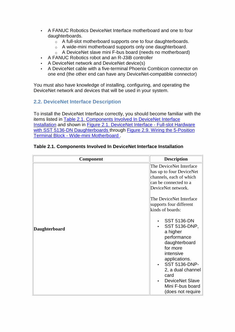
Daughterboard
The DeviceNet Interface has up to four DeviceNet channels, each of which can be connected to a DeviceNet network.
The DeviceNet Interface supports four different kinds of boards:
• SST 5136-DN • SST 5136-DNP,
a higher performance daughterboard for more intensive applications.
• SST 5136-DNP-2, a dual channel card
• DeviceNet Slave Mini F-bus board (does not require
Component Description
a motherboard)
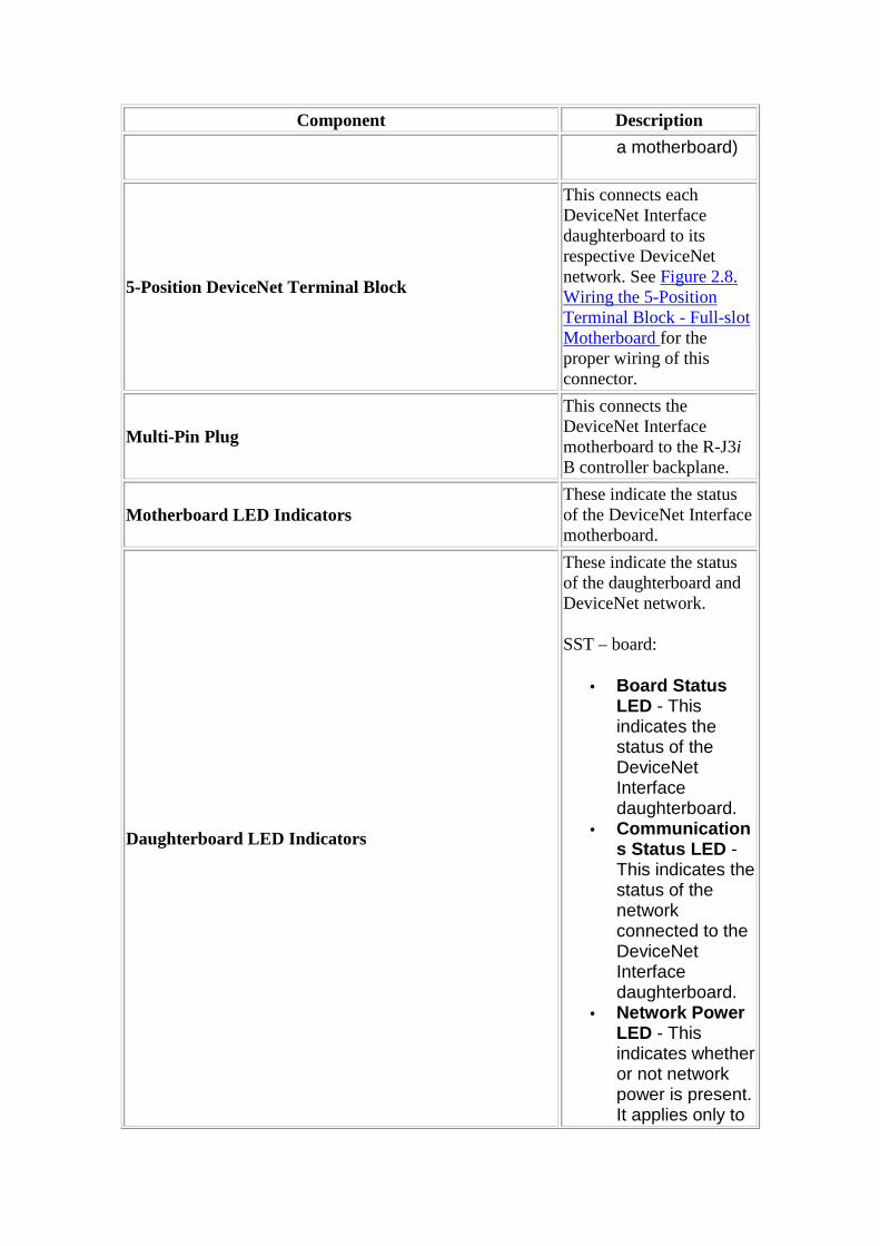
5-Position DeviceNet Terminal Block
This connects each DeviceNet Interface daughterboard to its respective DeviceNet network. See Figure 2.8. Wiring the 5-Position Terminal Block - Full-slot Motherboard for the proper wiring of this connector.
Multi-Pin Plug
This connects the DeviceNet Interface motherboard to the R-J3i B controller backplane.
Motherboard LED Indicators These indicate the status of the DeviceNet Interface motherboard.
Daughterboard LED Indicators
These indicate the status of the daughterboard and DeviceNet network.
SST – board:
• Board Status LED - This indicates the status of the DeviceNet Interface daughterboard.
• Communications Status LED - This indicates the status of the network connected to the DeviceNet Interface daughterboard.
• Network Power LED - This indicates whether or not network power is present. It applies only to
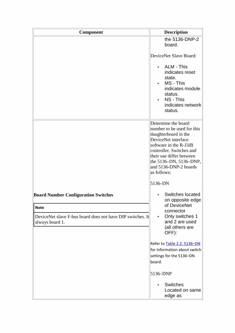
Component Description
the 5136-DNP-2 board.
DeviceNet Slave Board:
• ALM - This indicates reset state.
• MS - This indicates module status.
• NS - This indicates network status.
Board Number Configuration Switches
Note
DeviceNet slave F-bus board does not have DIP switches. It is always board 1.
Determine the board number to be used for this daughterboard in the DeviceNet interface software in the R-J3iB controller. Switches and their use differ between the 5136–DN, 5136–DNP, and 5136-DNP-2 boards as follows:
5136–DN
• Switches located on opposite edge of DeviceNet connector
• Only switches 1 and 2 are used (all others are OFF):
Refer to Table 2.2. 5136–DN
for information about switch
settings for the 5136–DN
board.
5136–DNP
• Switches Located on same edge as
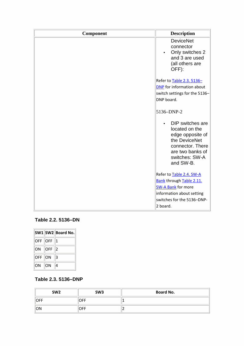
Component Description
DeviceNet connector
• Only switches 2 and 3 are used (all others are OFF):
Refer to Table 2.3. 5136–
DNP for information about
switch settings for the 5136–
DNP board.
5136–DNP-2
• DIP switches are located on the edge opposite of the DeviceNet connector. There are two banks of switches: SW-A and SW-B.
Refer to Table 2.4. SW-A
Bank through Table 2.11.
SW-A Bank for more
information about setting
switches for the 5136–DNP-
2 board.
Table 2.2. 5136–DN
SW1 SW2 Board No.
OFF OFF 1
ON OFF 2
OFF ON 3
ON ON 4
Table 2.3. 5136–DNP
SW2 SW3 Board No.
OFF OFF 1
ON OFF 2
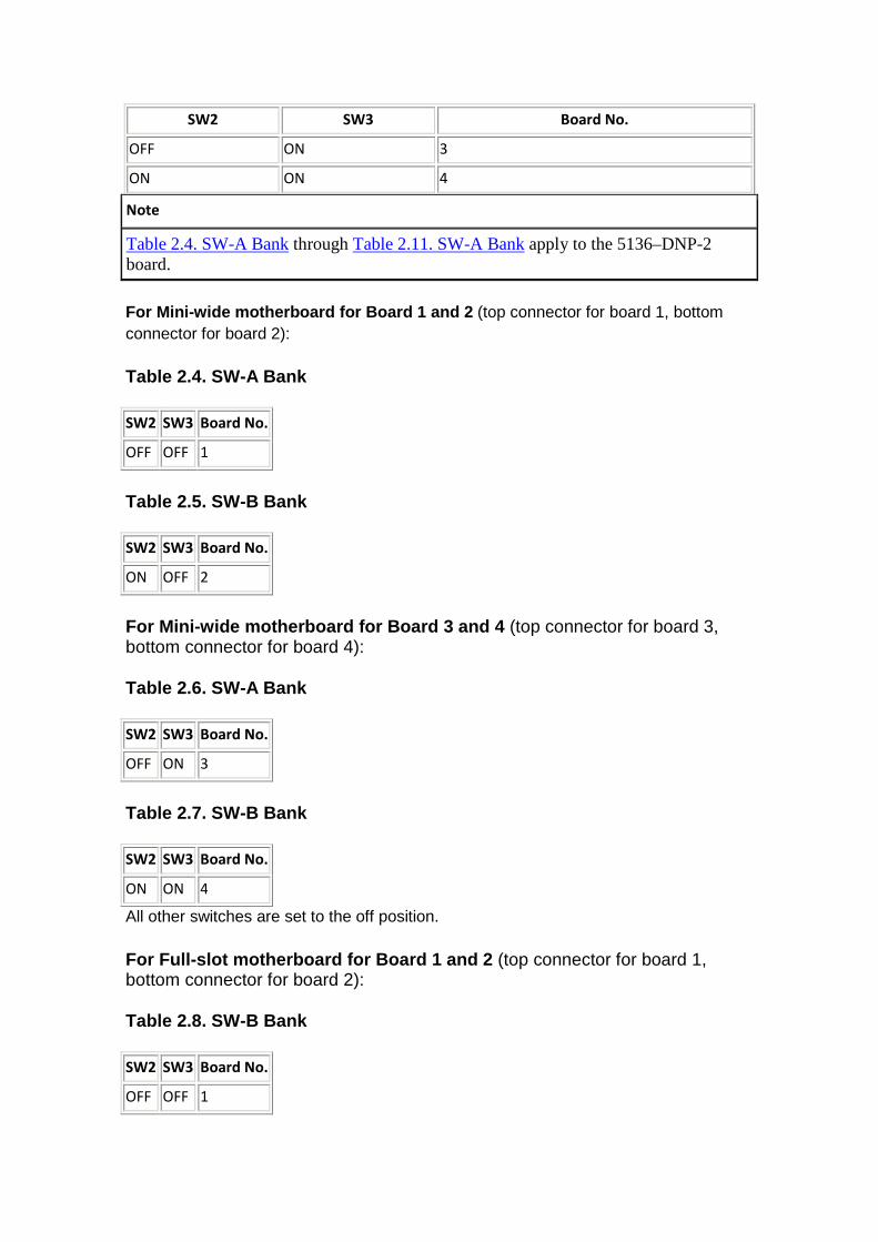
SW2 SW3 Board No.
OFF ON 3
ON ON 4
Note
Table 2.4. SW-A Bank through Table 2.11. SW-A Bank apply to the 5136–DNP-2 board.
For Mini-wide motherboard for Board 1 and 2 (top connector for board 1, bottom connector for board 2):
Table 2.4. SW-A Bank
SW2 SW3 Board No.
OFF OFF 1
Table 2.5. SW-B Bank
SW2 SW3 Board No.
ON OFF 2
For Mini-wide motherboard for Board 3 and 4 (top connector for board 3, bottom connector for board 4):
Table 2.6. SW-A Bank
SW2 SW3 Board No.
OFF ON 3
Table 2.7. SW-B Bank
SW2 SW3 Board No.
ON ON 4
All other switches are set to the off position.
For Full-slot motherboard for Board 1 and 2 (top connector for board 1, bottom connector for board 2):
Table 2.8. SW-B Bank
SW2 SW3 Board No.
OFF OFF 1
Table 2.9. SW-A Bank
SW2 SW3 Board No.
ON OFF 2
For Full-slot motherboard for Board 3 and 4 (top connector for board 3, bottom connector for board 4):
Table 2.10. SW-B Bank
SW2 SW3 Board No.
OFF ON 3
Table 2.11. SW-A Bank
SW2 SW3 Board No.
ON ON 4
Figure 2.1. DeviceNet Interface - Full-slot Hardwar e with SST 5136-DN Daughterboards
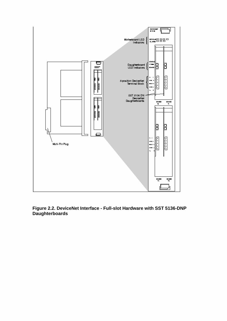
Figure 2.2. DeviceNet Interface - Full-slot Hardwar e with SST 5136-DNP Daughterboards
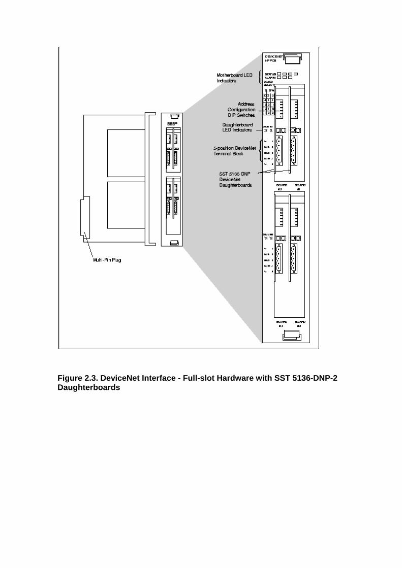
Figure 2.3. DeviceNet Interface - Full-slot Hardwar e with SST 5136-DNP-2 Daughterboards
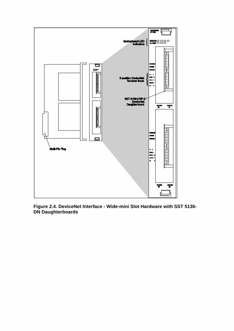
Figure 2.4. DeviceNet Interface - Wide-mini Slot Ha rdware with SST 5136-DN Daughterboards
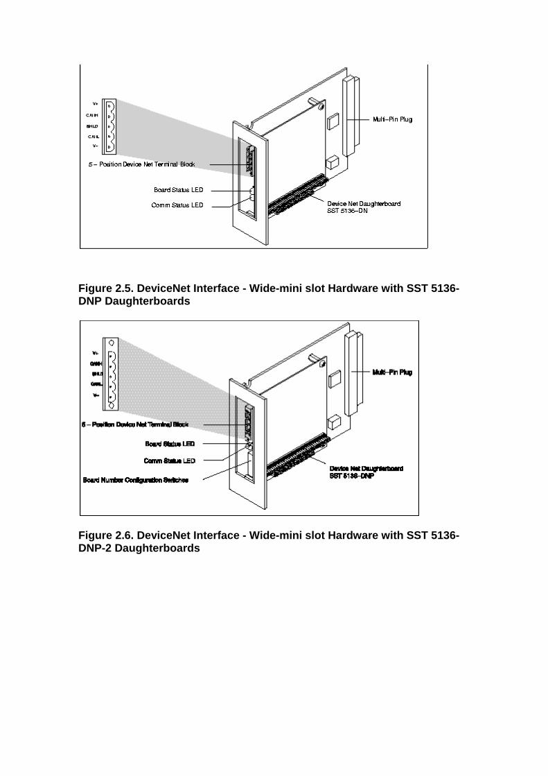
Figure 2.5. DeviceNet Interface - Wide-mini slot Ha rdware with SST 5136-DNP Daughterboards
Figure 2.6. DeviceNet Interface - Wide-mini slot Ha rdware with SST 5136-DNP-2 Daughterboards
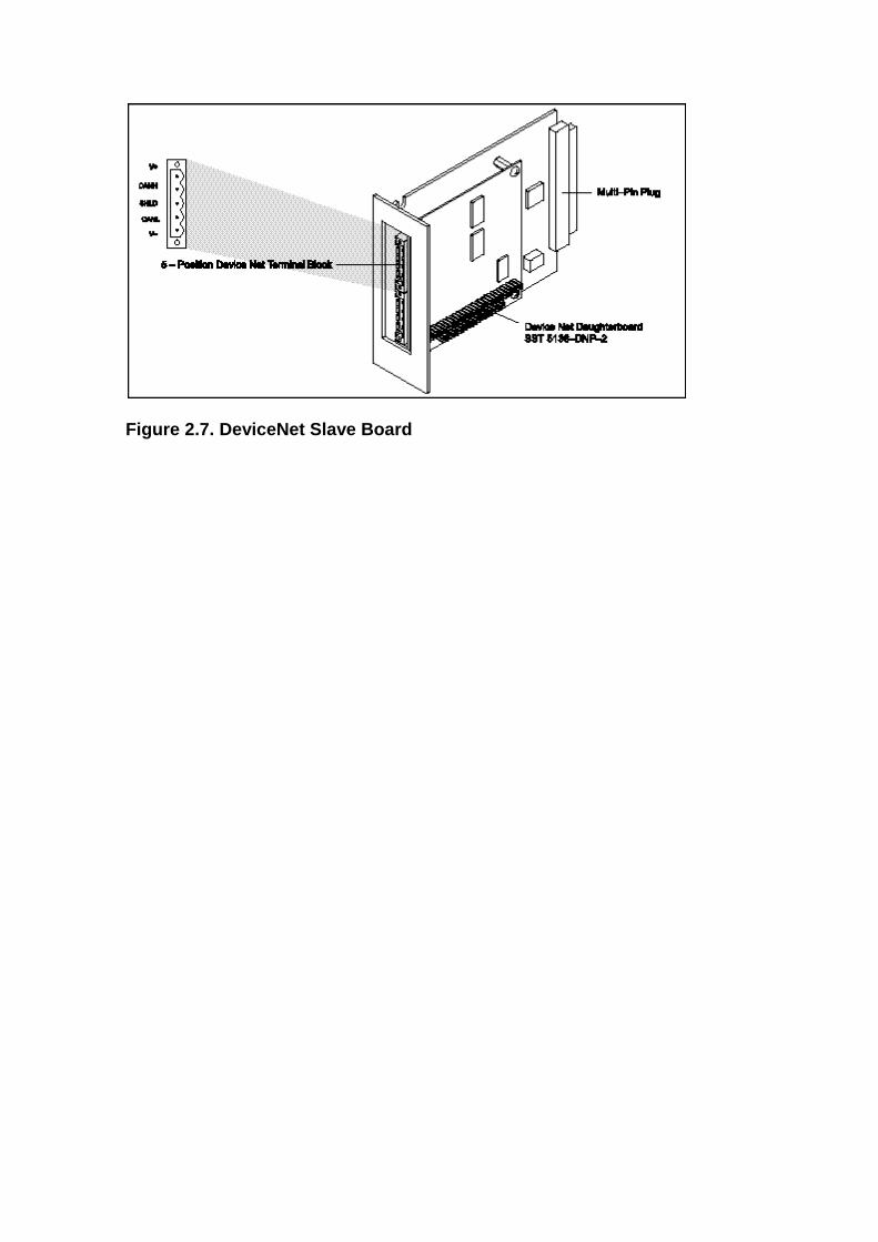
Figure 2.7. DeviceNet Slave Board
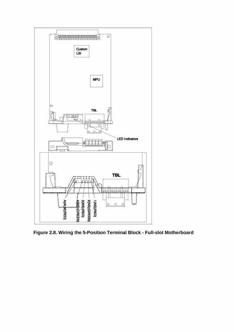
Figure 2.8. Wiring the 5-Position Terminal Block - Full-slot Motherboard
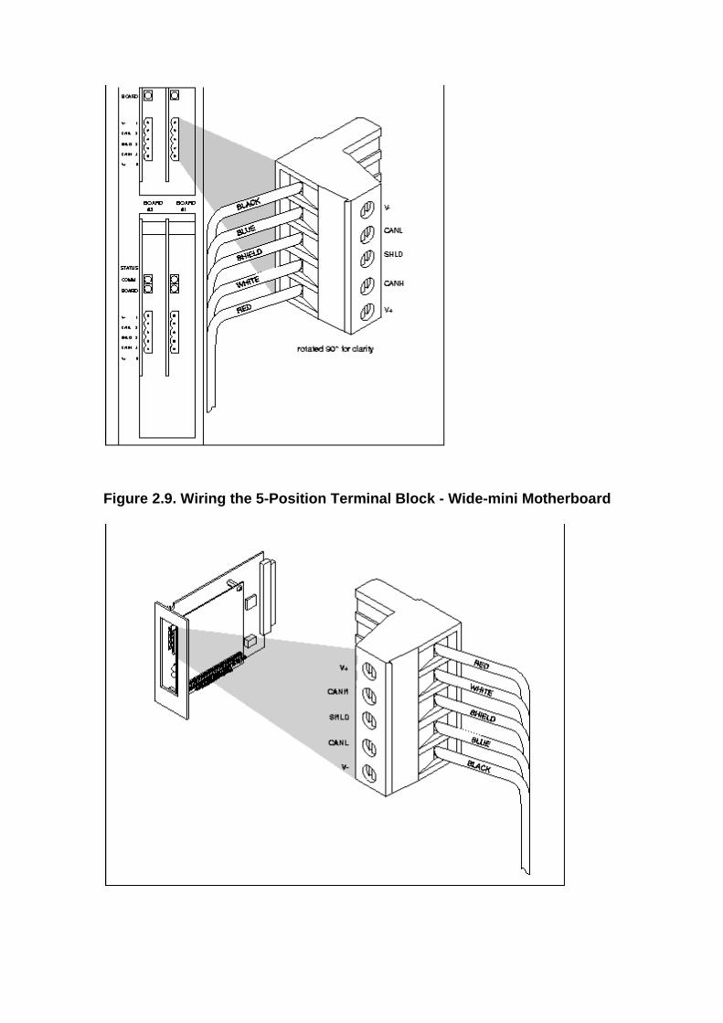
Figure 2.9. Wiring the 5-Position Terminal Block - Wide-mini Motherboard
2.3. DeviceNet Network Requirements
The DeviceNet Interface is connected to a DeviceNet network. It consists of the following customer-supplied components:
• Trunk line cable • T-connectors • Drop cables • Termination resistors - one resistor is needed on each end of the trunk
line. • DeviceNet- compatible devices
The following components are optional:
• External master device (such as a PLC) with a separate DeviceNet scanner
• A DeviceNet network configuration device or software for devices that can be configured only through software
2.4. DeviceNet Interface Installation and Configura tion
Installing and configuring the DeviceNet Interface on the R-J3iB controller requires that you perform the following steps:
1. Install the DeviceNet Interface board in the R-J3iB controller. Refer to Section 2.4.1.
2. Configure each DeviceNet Interface daughterboard. Refer toSection 3.1. 3. Connect each DeviceNet Interface daughterboard to the corresponding
DeviceNet network. Refer to Section 3.1. 4. Power up the controller. At controlled start, install the DeviceNet software
option. Refer to the FANUC Robotics SYSTEM R-J3iB Controller Software Installation Manual.
5. Turn on power to the system and check for proper installation. Refer to Section 2.4.1.
6. Define DeviceNet devices connected to each DeviceNet daughterboard. Refer to Section 5.1.
In addition, you can configure the DeviceNet Interface as follows. Use these configurations only if you want to use the DeviceNet Interface in either of these ways.
• Configure a DeviceNet Interface daughterboard for slave operation. Refer to Section 4.1.
• Configure multiple-module DeviceNet devices. Refer to Section 5.2.
2.4.1. Installing the DeviceNet Interface Board in the R-J3 iB Controller
Use Procedure 2.1. Installing the DeviceNet Interface in the R-J3iB Controller to install the DeviceNet Interface.
Procedure 2.1. Installing the DeviceNet Interface i n the R-J3 iB Controller
Warning
Disconnect electrical power from the controller before you remove or replace components, or you could be injured seriously.
Steps
1. Turn off the controller. 2. Disconnect electrical power from the controller. Turn the circuit breaker
handle to the OFF (open) position.
Warning
When the circuit breaker handle is OFF, power is still present inside the controller. You must unplug the controller from the electrical outlet to remove all power from the controller.
3. 4. Use a flat-tip screwdriver to turn the latch on the front door of the
controller to the UNLOCKED position. 5. To install the DeviceNet Interface, plug in the DeviceNet Interface to
an appropriate empty slot on the backplane. Be sure the connector seats properly with the backplane connector.
Figure 2.10. Installing the DeviceNet Interface int o Full-width Slot
No se puede mostrar la imagen. Puede que su equipo no tenga suficiente memoria para abrir la imagen o que ésta esté dañada. Reinicie el equipo y, a continuación, abra el archivo de nuevo. Si sigue apareciendo la x roja, puede que tenga que borrar la imagen e insertarla de nuevo.
No se puede mostrar la imagen. Puede que su equipo no tenga suficiente memoria para abrir la imagen o que ésta esté dañada. Reinicie el equipo y, a continuación, abra el archivo de nuevo. Si sigue apareciendo la x roja, puede que tenga que borrar la imagen e insertarla de nuevo.
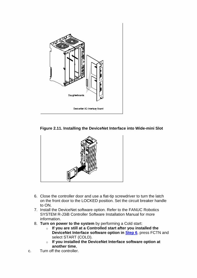
Figure 2.11. Installing the DeviceNet Interface int o Wide-mini Slot
6. Close the controller door and use a flat-tip screwdriver to turn the latch on the front door to the LOCKED position. Set the circuit breaker handle to ON.
7. Install the DeviceNet software option. Refer to the FANUC Robotics SYSTEM R-J3iB Controller Software Installation Manual for more information.
8. Turn on power to the system by performing a Cold start: o If you are still at a Controlled start after you in stalled the
DeviceNet Interface software option in Step 6 , press FCTN and select START (COLD).
o If you installed the DeviceNet Interface software o ption at another time ,
c. Turn off the controller.

d. Press and continue pressing the SHIFT and RESET keys on the teach pendant. e. Press the ON button on the operator panel. f. Release SHIFT and RESET.
Note
After the controller has come up in Cold start mode, the BOARD STATUS LED on each DeviceNet Interface daughterboard should be STEADY GREEN.
g. 9. Configure each DeviceNet Interface daughterboard. Refer to Section 3.1.
3. DeviceNet Board Setup and Configuration
3.1. Configuring and Connecting the DeviceNet Inter face Daughterboards
Before you can connect the DeviceNet Interface daughterboards to devices on the DeviceNet network, you must configure them properly. Use Procedure 3.1. Configuring and Connecting DeviceNet Interface Daughterboards to configure the daughterboards.
When you configure DeviceNet Interface daughterboards, you use two screens: the I/O DeviceNet Board List screen and the I/O DeviceNet Board Detail screen. Refer to Table 3.1. DeviceNet Board List Screen Items and Table 3.2. DeviceNet Board Detail Screen Items for a listing and description of each of the items on these screens.
Table 3.1. DeviceNet Board List Screen Items
ITEM DESCRIPTION
Board This is the number of the DeviceNet Interface daughterboard, 1–4.
Comment This is text you enter to describe the daughterboard. A comment is not required.
Rack
This is the I/O rack that will be used to configure the I/O used with the daughterboard on the controller. DeviceNet Interface daughterboards must use racks 81 through 84:
• Rack 81 - Daughterboard 1 • Rack 82 - Daughterboard 2 • Rack 83 - Daughterboard 3 • Rack 84 - Daughterboard 4
You cannot change the rack number of a daughterboard.
Status This is the current state of the DeviceNet Interface daughterboard.
• ONLINE indicates the board is presently active. Information to and from devices configured on this network is being updated.
• OFFLINE indicates that no data is being transferred to or from devices connected to the board. Scanning of devices connected to this board will not start at power up.
• ERROR indicates that an error has been detected. The board is effectively off-line, but scanning will be attempted after power up.
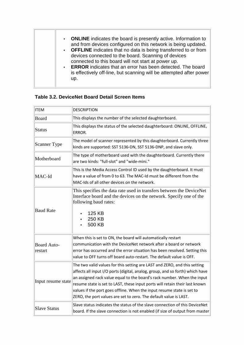
Table 3.2. DeviceNet Board Detail Screen Items
ITEM DESCRIPTION
Board This displays the number of the selected daughterboard.
Status This displays the status of the selected daughterboard: ONLINE, OFFLINE,
ERROR.
Scanner Type The model of scanner represented by this daughterboard. Currently three
kinds are supported: SST 5136-DN, SST 5136-DNP, and slave only.
Motherboard The type of motherboard used with the daughterboard. Currently there
are two kinds: "full-slot" and "wide-mini."
MAC-Id
This is the Media Access Control ID used by the daughterboard. It must
have a value of from 0 to 63. The MAC-Id must be different from the
MAC-Ids of all other devices on the network.
Baud Rate
This specifies the data rate used in transfers between the DeviceNet Interface board and the devices on the network. Specify one of the following baud rates:
• 125 KB • 250 KB • 500 KB
Board Auto-restart
When this is set to ON, the board will automatically restart
communication with the DeviceNet network after a board or network
error has occurred and the error situation has been resolved. Setting this
value to OFF turns off board auto-restart. The default value is OFF.
Input resume state
The two valid values for this setting are LAST and ZERO, and this setting
affects all input I/O ports (digital, analog, group, and so forth) which have
an assigned rack value equal to the board's rack number. When the input
resume state is set to LAST, these input ports will retain their last known
values if the port goes offline. When the input resume state is set to
ZERO, the port values are set to zero. The default value is LAST.
Slave Status Slave status indicates the status of the slave connection of this DeviceNet
board. If the slave connection is not enabled (if size of output from master
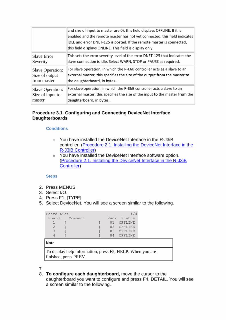
and size of input to master are 0), this field displays OFFLINE. If it is
enabled and the remote master has not yet connected, this field indicates
IDLE and error DNET-125 is posted. If the remote master is connected,
this field displays ONLINE. This field is display only.
Slave Error Severity
This sets the error severity level of the error DNET-125 that indicates the
slave connection is idle. Select WARN, STOP or PAUSE as required.
Slave Operation: Size of output from master
For slave operation, in which the R-J3iB controller acts as a slave to an
external master, this specifies the size of the output from the master to
the daughterboard, in bytes..
Slave Operation: Size of input to master
For slave operation, in which the R-J3iB controller acts a slave to an
external master, this specifies the size of the input to the master from the
daughterboard, in bytes..
Procedure 3.1. Configuring and Connecting DeviceNet Interface Daughterboards
Conditions
o You have installed the DeviceNet Interface in the R-J3iB controller. (Procedure 2.1. Installing the DeviceNet Interface in the R-J3iB Controller)
o You have installed the DeviceNet Interface software option. (Procedure 2.1. Installing the DeviceNet Interface in the R-J3iB Controller)
Steps
2. Press MENUS. 3. Select I/O. 4. Press F1, [TYPE]. 5. Select DeviceNet. You will see a screen similar to the following.
Board List 1/4 Board Comment Rack Status 1 [ ] 81 OFFLINE 2 [ ] 82 OFFLINE 3 [ ] 83 OFFLINE 4 [ ] 84 OFFLINE
Note
To display help information, press F5, HELP. When you are finished, press PREV.
7. 8. To configure each daughterboard, move the cursor to the
daughterboard you want to configure and press F4, DETAIL. You will see a screen similar to the following.
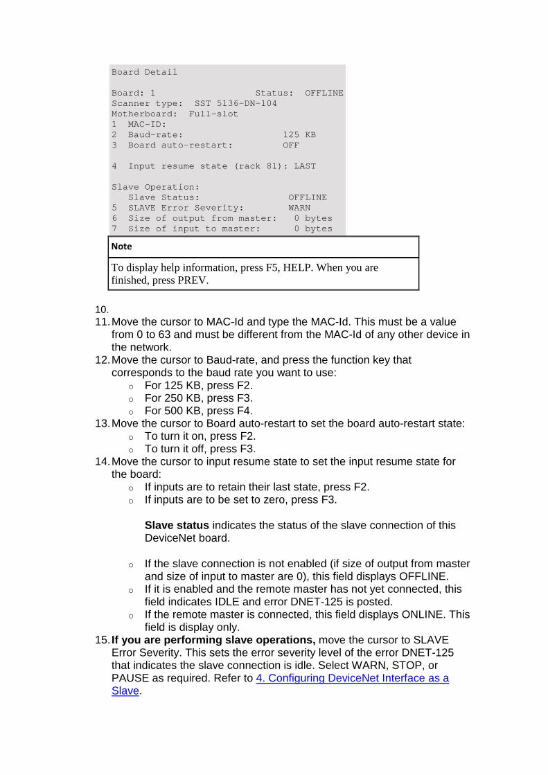
Board Detail Board: 1 Status: OFFLINE Scanner type: SST 5136-DN-104 Motherboard: Full-slot 1 MAC-ID: 2 Baud-rate: 125 KB 3 Board auto-restart: OFF 4 Input resume state (rack 81): LAST Slave Operation: Slave Status: OFFLINE 5 SLAVE Error Severity: WARN 6 Size of output from master: 0 bytes 7 Size of input to master: 0 bytes
Note
To display help information, press F5, HELP. When you are finished, press PREV.
10. 11. Move the cursor to MAC-Id and type the MAC-Id. This must be a value
from 0 to 63 and must be different from the MAC-Id of any other device in the network.
12. Move the cursor to Baud-rate, and press the function key that corresponds to the baud rate you want to use:
o For 125 KB, press F2. o For 250 KB, press F3. o For 500 KB, press F4.
13. Move the cursor to Board auto-restart to set the board auto-restart state: o To turn it on, press F2. o To turn it off, press F3.
14. Move the cursor to input resume state to set the input resume state for the board:
o If inputs are to retain their last state, press F2. o If inputs are to be set to zero, press F3.
Slave status indicates the status of the slave connection of this DeviceNet board.
o If the slave connection is not enabled (if size of output from master and size of input to master are 0), this field displays OFFLINE.
o If it is enabled and the remote master has not yet connected, this field indicates IDLE and error DNET-125 is posted.
o If the remote master is connected, this field displays ONLINE. This field is display only.
15. If you are performing slave operations, move the cursor to SLAVE Error Severity. This sets the error severity level of the error DNET-125 that indicates the slave connection is idle. Select WARN, STOP, or PAUSE as required. Refer to 4. Configuring DeviceNet Interface as a Slave.
Note
This affects only DNET-125 error posted by the DeviceNet interface.
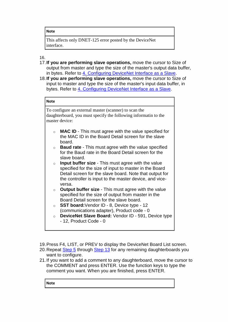
16. 17. If you are performing slave operations, move the cursor to Size of
output from master and type the size of the master's output data buffer, in bytes. Refer to 4. Configuring DeviceNet Interface as a Slave.
18. If you are performing slave operations, move the cursor to Size of input to master and type the size of the master's input data buffer, in bytes. Refer to 4. Configuring DeviceNet Interface as a Slave.
Note
To configure an external master (scanner) to scan the daughterboard, you must specify the following informatin to the master device:
o MAC ID - This must agree with the value specified for the MAC ID in the Board Detail screen for the slave board.
o Baud rate - This must agree with the value specified for the Baud rate in the Board Detail screen for the slave board.
o Input buffer size - This must agree with the value specified for the size of input to master in the Board Detail screen for the slave board. Note that output for the controller is input to the master device, and vice-versa.
o Output buffer size - This must agree with the value specified for the size of output from master in the Board Detail screen for the slave board.
o SST board: Vendor ID - 8, Device type - 12 (communications adapter), Product code - 0
o DeviceNet Slave Board: Vendor ID - 591, Device type - 12, Product Code - 0
19. Press F4, LIST, or PREV to display the DeviceNet Board List screen. 20. Repeat Step 5 through Step 13 for any remaining daughterboards you
want to configure. 21. If you want to add a comment to any daughterboard, move the cursor to
the COMMENT and press ENTER. Use the function keys to type the comment you want. When you are finished, press ENTER.
Note
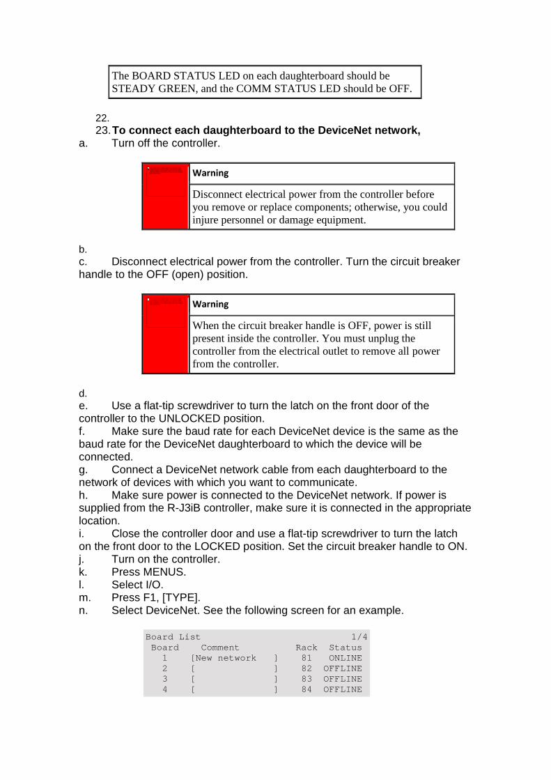
The BOARD STATUS LED on each daughterboard should be STEADY GREEN, and the COMM STATUS LED should be OFF.
22. 23. To connect each daughterboard to the DeviceNet netw ork,
a. Turn off the controller.
Warning
Disconnect electrical power from the controller before you remove or replace components; otherwise, you could injure personnel or damage equipment.
b. c. Disconnect electrical power from the controller. Turn the circuit breaker handle to the OFF (open) position.
Warning
When the circuit breaker handle is OFF, power is still present inside the controller. You must unplug the controller from the electrical outlet to remove all power from the controller.
d. e. Use a flat-tip screwdriver to turn the latch on the front door of the controller to the UNLOCKED position. f. Make sure the baud rate for each DeviceNet device is the same as the baud rate for the DeviceNet daughterboard to which the device will be connected. g. Connect a DeviceNet network cable from each daughterboard to the network of devices with which you want to communicate. h. Make sure power is connected to the DeviceNet network. If power is supplied from the R-J3iB controller, make sure it is connected in the appropriate location. i. Close the controller door and use a flat-tip screwdriver to turn the latch on the front door to the LOCKED position. Set the circuit breaker handle to ON. j. Turn on the controller. k. Press MENUS. l. Select I/O. m. Press F1, [TYPE]. n. Select DeviceNet. See the following screen for an example.
Board List 1/4 Board Comment Rack Status 1 [New network ] 81 ONLINE 2 [ ] 82 OFFLINE 3 [ ] 83 OFFLINE 4 [ ] 84 OFFLINE
No se puede mostrar la imagen. Puede que su equipo no tenga suficiente memoria para abrir la imagen o que ésta esté dañada. Reinicie el equipo y, a continuación, abra el archivo de nuevo. Si sigue apareciendo la x roja, puede que tenga que borrar la imagen e insertarla de nuevo.
No se puede mostrar la imagen. Puede que su equipo no tenga
suficiente memoria para abrir la imagen o que ésta esté dañada. Reinicie el equipo y, a continuación, abra el archivo de nuevo. Si sigue apareciendo la x roja, puede que tenga que borrar la imagen e insertarla de nuevo.
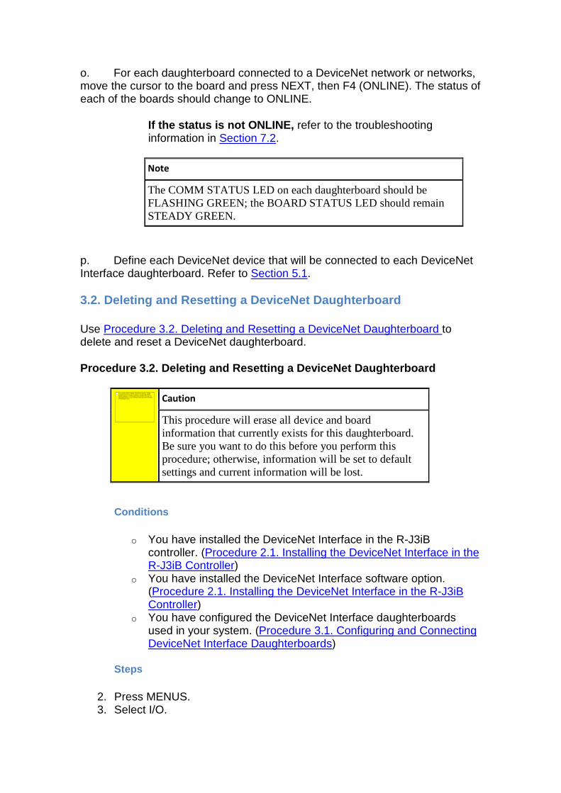
o. For each daughterboard connected to a DeviceNet network or networks, move the cursor to the board and press NEXT, then F4 (ONLINE). The status of each of the boards should change to ONLINE.
If the status is not ONLINE, refer to the troubleshooting information in Section 7.2.
Note
The COMM STATUS LED on each daughterboard should be FLASHING GREEN; the BOARD STATUS LED should remain STEADY GREEN.
p. Define each DeviceNet device that will be connected to each DeviceNet Interface daughterboard. Refer to Section 5.1.
3.2. Deleting and Resetting a DeviceNet Daughterboa rd
Use Procedure 3.2. Deleting and Resetting a DeviceNet Daughterboard to delete and reset a DeviceNet daughterboard.
Procedure 3.2. Deleting and Resetting a DeviceNet D aughterboard
Caution
This procedure will erase all device and board information that currently exists for this daughterboard. Be sure you want to do this before you perform this procedure; otherwise, information will be set to default settings and current information will be lost.
Conditions
o You have installed the DeviceNet Interface in the R-J3iB controller. (Procedure 2.1. Installing the DeviceNet Interface in the R-J3iB Controller)
o You have installed the DeviceNet Interface software option. (Procedure 2.1. Installing the DeviceNet Interface in the R-J3iB Controller)
o You have configured the DeviceNet Interface daughterboards used in your system. (Procedure 3.1. Configuring and Connecting DeviceNet Interface Daughterboards)
Steps
2. Press MENUS. 3. Select I/O.
No se puede mostrar la imagen. Puede que su equipo no tenga suficiente memoria para abrir la imagen o que ésta esté dañada. Reinicie el equipo y, a continuación, abra el archivo de nuevo. Si sigue apareciendo la x roja, puede que tenga que borrar la imagen e insertarla de nuevo.
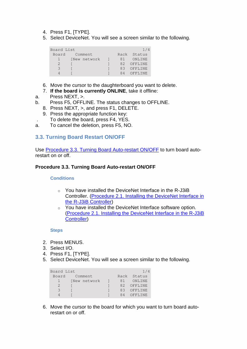
4. Press F1, [TYPE]. 5. Select DeviceNet. You will see a screen similar to the following.
Board List 1/4 Board Comment Rack Status 1 [New network ] 81 ONLINE 2 [ ] 82 OFFLINE 3 [ ] 83 OFFLINE 4 [ ] 84 OFFLINE
6. Move the cursor to the daughterboard you want to delete. 7. If the board is currently ONLINE , take it offline:
a. Press NEXT, >. b. Press F5, OFFLINE. The status changes to OFFLINE.
8. Press NEXT, >, and press F1, DELETE. 9. Press the appropriate function key:
. To delete the board, press F4, YES. a. To cancel the deletion, press F5, NO.
3.3. Turning Board Restart ON/OFF
Use Procedure 3.3. Turning Board Auto-restart ON/OFF to turn board auto-restart on or off.
Procedure 3.3. Turning Board Auto-restart ON/OFF
Conditions
o You have installed the DeviceNet Interface in the R-J3iB Controller. (Procedure 2.1. Installing the DeviceNet Interface in the R-J3iB Controller)
o You have installed the DeviceNet Interface software option. (Procedure 2.1. Installing the DeviceNet Interface in the R-J3iB Controller)
Steps
2. Press MENUS. 3. Select I/O. 4. Press F1, [TYPE]. 5. Select DeviceNet. You will see a screen similar to the following.
Board List 1/4 Board Comment Rack Status 1 [New network ] 81 ONLINE 2 [ ] 82 OFFLINE 3 [ ] 83 OFFLINE 4 [ ] 84 OFFLINE
6. Move the cursor to the board for which you want to turn board auto-restart on or off.
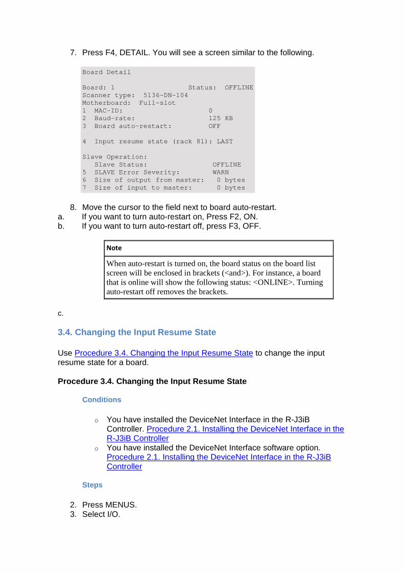
7. Press F4, DETAIL. You will see a screen similar to the following.
Board Detail Board: 1 Status: OFFLINE Scanner type: 5136-DN-104 Motherboard: Full-slot 1 MAC-ID: 0 2 Baud-rate: 125 KB 3 Board auto-restart: OFF 4 Input resume state (rack 81): LAST Slave Operation: Slave Status: OFFLINE 5 SLAVE Error Severity: WARN 6 Size of output from master: 0 bytes 7 Size of input to master: 0 bytes
8. Move the cursor to the field next to board auto-restart. a. If you want to turn auto-restart on, Press F2, ON. b. If you want to turn auto-restart off, press F3, OFF.
Note
When auto-restart is turned on, the board status on the board list screen will be enclosed in brackets (<and>). For instance, a board that is online will show the following status: <ONLINE>. Turning auto-restart off removes the brackets.
c.
3.4. Changing the Input Resume State
Use Procedure 3.4. Changing the Input Resume State to change the input resume state for a board.
Procedure 3.4. Changing the Input Resume State
Conditions
o You have installed the DeviceNet Interface in the R-J3iB Controller. Procedure 2.1. Installing the DeviceNet Interface in the R-J3iB Controller
o You have installed the DeviceNet Interface software option. Procedure 2.1. Installing the DeviceNet Interface in the R-J3iB Controller
Steps
2. Press MENUS. 3. Select I/O.
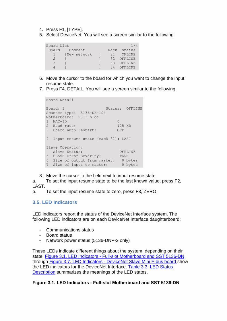
4. Press F1, [TYPE]. 5. Select DeviceNet. You will see a screen similar to the following.
Board List 1/4 Board Comment Rack Status 1 [New network ] 81 ONLINE 2 [ ] 82 OFFLINE 3 [ ] 83 OFFLINE 4 [ ] 84 OFFLINE
6. Move the cursor to the board for which you want to change the input resume state.
7. Press F4, DETAIL. You will see a screen similar to the following.
Board Detail Board: 1 Status: OFFLINE Scanner type: 5136-DN-104 Motherboard: Full-slot 1 MAC-ID: 0 2 Baud-rate: 125 KB 3 Board auto-restart: OFF 4 Input resume state (rack 81): LAST Slave Operation: Slave Status: OFFLINE 5 SLAVE Error Severity: WARN 6 Size of output from master: 0 bytes 7 Size of input to master: 0 bytes
8. Move the cursor to the field next to input resume state. a. To set the input resume state to be the last known value, press F2, LAST. b. To set the input resume state to zero, press F3, ZERO.
3.5. LED Indicators
LED indicators report the status of the DeviceNet Interface system. The following LED indicators are on each DeviceNet Interface daughterboard:
• Communications status • Board status • Network power status (5136-DNP-2 only)
These LEDs indicate different things about the system, depending on their state. Figure 3.1. LED Indicators - Full-slot Motherboard and SST 5136-DN through Figure 3.7. LED Indicators - DeviceNet Slave Mini F-bus board show the LED indicators for the DeviceNet Interface. Table 3.3. LED Status Description summarizes the meanings of the LED states.
Figure 3.1. LED Indicators - Full-slot Motherboard and SST 5136-DN
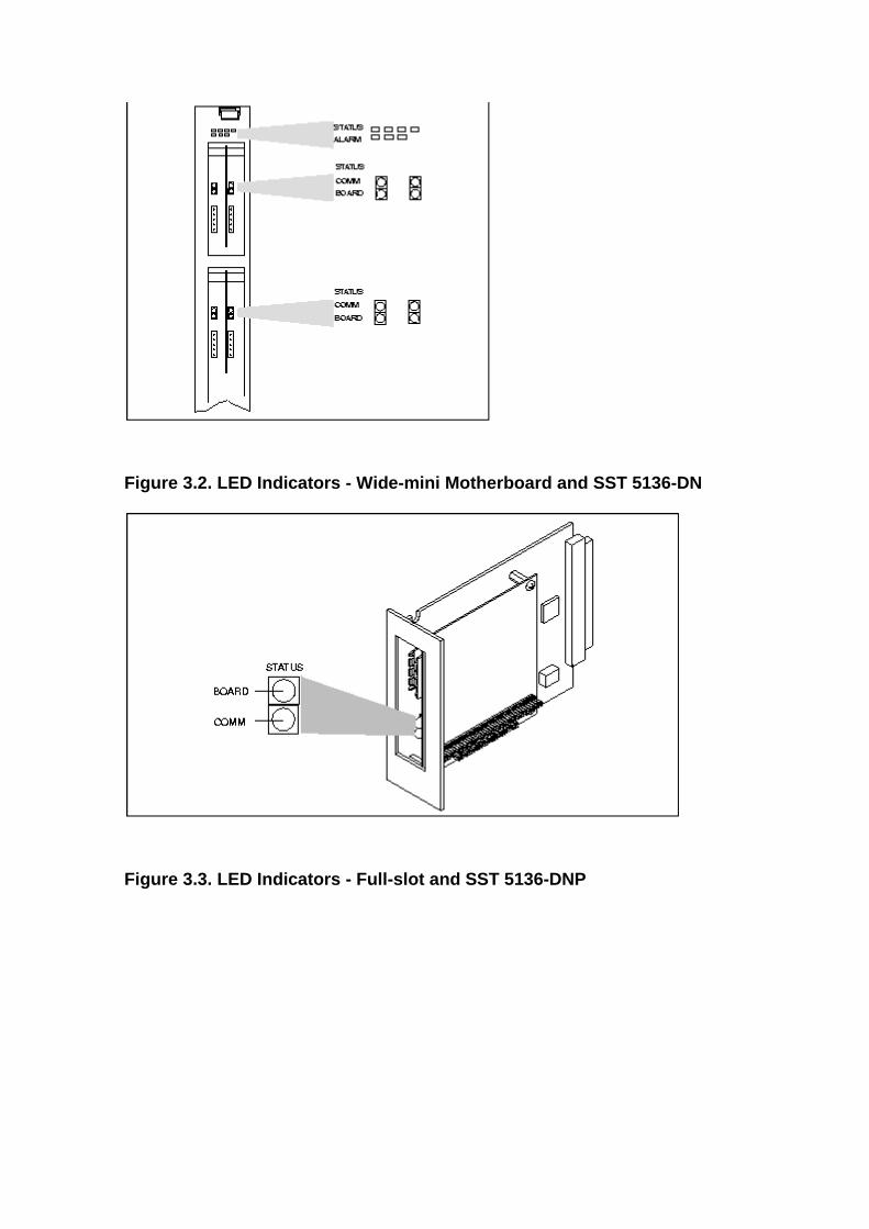
Figure 3.2. LED Indicators - Wide-mini Motherboard and SST 5136-DN
Figure 3.3. LED Indicators - Full-slot and SST 5136 -DNP
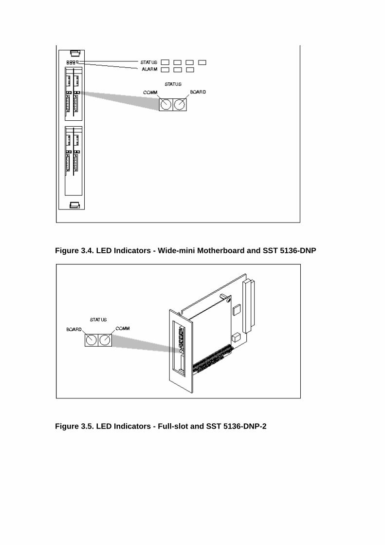
Figure 3.4. LED Indicators - Wide-mini Motherboard and SST 5136-DNP
Figure 3.5. LED Indicators - Full-slot and SST 5136 -DNP-2
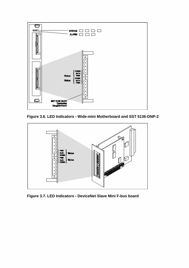
Figure 3.6. LED Indicators - Wide-mini Motherboard and SST 5136-DNP-2
Figure 3.7. LED Indicators - DeviceNet Slave Mini F -bus board
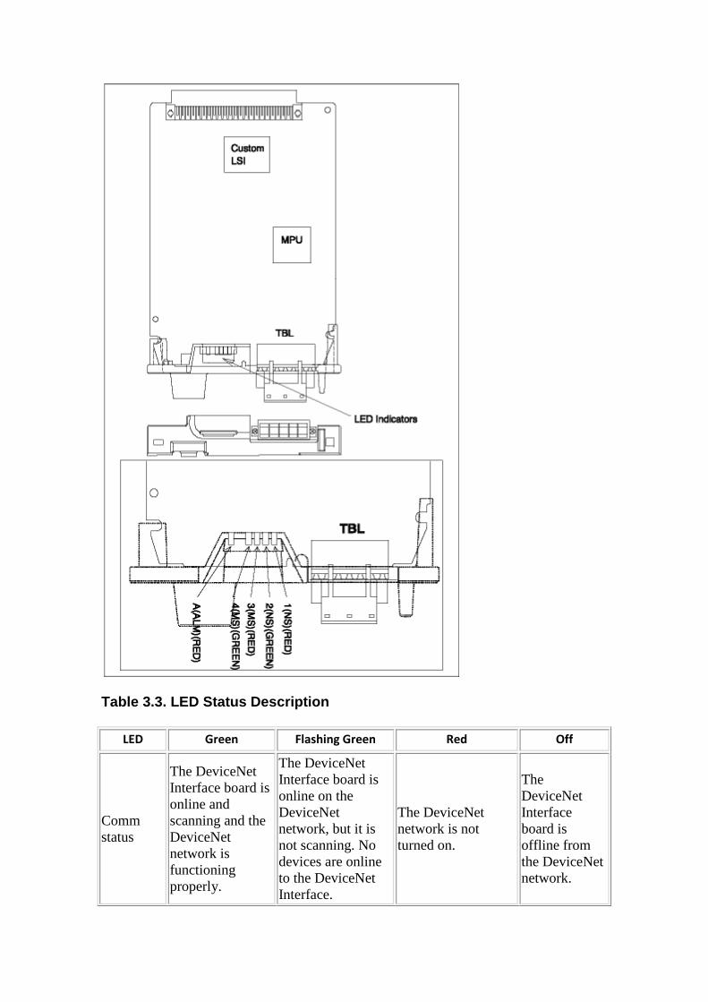
Table 3.3. LED Status Description
LED Green Flashing Green Red Off
Comm status
The DeviceNet Interface board is online and scanning and the DeviceNet network is functioning properly.
The DeviceNet Interface board is online on the DeviceNet network, but it is not scanning. No devices are online to the DeviceNet Interface.
The DeviceNet network is not turned on.
The DeviceNet Interface board is offline from the DeviceNet network.
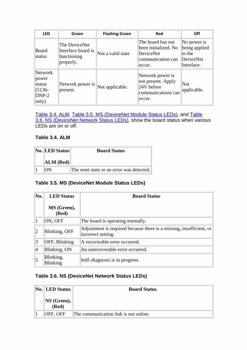
LED Green Flashing Green Red Off
Board status
The DeviceNet Interface board is functioning properly.
Not a valid state
The board has not been initialized. No DeviceNet communication can occur.
No power is being applied to the DeviceNet Interface.
Network power status (5136-DNP-2 only)
Network power is present.
Not applicable.
Network power is not present. Apply 24V before communications can occur.
Not applicable.
Table 3.4. ALM, Table 3.5. MS (DeviceNet Module Status LEDs), and Table 3.6. NS (DeviceNet Network Status LEDs), show the board status when various LEDs are on or off.
Table 3.4. ALM
No. LED Status
ALM (Red)
Board Status
1 ON The reset state or an error was detected.
Table 3.5. MS (DeviceNet Module Status LEDs)
No. LED Status
MS (Green), (Red)
Board Status
1 ON, OFF The board is operating normally.
2 Blinking, OFF Adjustment is required because there is a missing, insufficient, or incorrect setting.
3 OFF, Blinking A recoverable error occurred.
4 Blinking, ON An unrecoverable error occurred.
5 Blinking, Blinking
Self–diagnosis is in progress.
Table 3.6. NS (DeviceNet Network Status LEDs)
No. LED Status
NS (Green), (Red)
Board Status
1 OFF, OFF The communication link is not online.
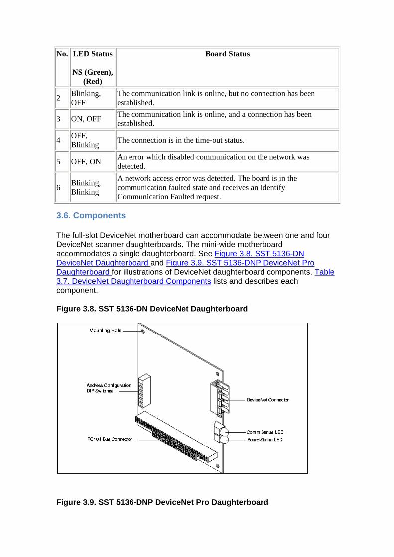
No. LED Status
NS (Green), (Red)
Board Status
2 Blinking, OFF
The communication link is online, but no connection has been established.
3 ON, OFF The communication link is online, and a connection has been established.
4 OFF, Blinking
The connection is in the time-out status.
5 OFF, ON An error which disabled communication on the network was detected.
6 Blinking, Blinking
A network access error was detected. The board is in the communication faulted state and receives an Identify Communication Faulted request.
3.6. Components
The full-slot DeviceNet motherboard can accommodate between one and four DeviceNet scanner daughterboards. The mini-wide motherboard accommodates a single daughterboard. See Figure 3.8. SST 5136-DN DeviceNet Daughterboard and Figure 3.9. SST 5136-DNP DeviceNet Pro Daughterboard for illustrations of DeviceNet daughterboard components. Table 3.7. DeviceNet Daughterboard Components lists and describes each component.
Figure 3.8. SST 5136-DN DeviceNet Daughterboard
Figure 3.9. SST 5136-DNP DeviceNet Pro Daughterboar d
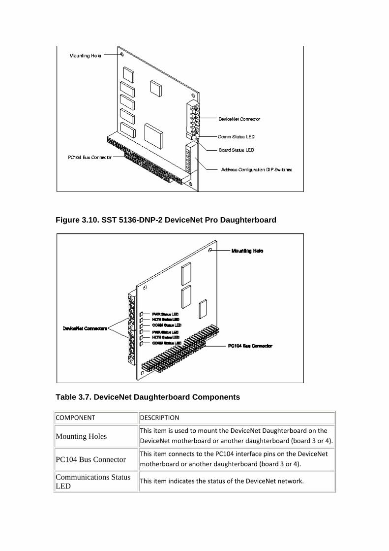
Figure 3.10. SST 5136-DNP-2 DeviceNet Pro Daughterb oard
Table 3.7. DeviceNet Daughterboard Components
COMPONENT DESCRIPTION
Mounting Holes This item is used to mount the DeviceNet Daughterboard on the
DeviceNet motherboard or another daughterboard (board 3 or 4).
PC104 Bus Connector This item connects to the PC104 interface pins on the DeviceNet
motherboard or another daughterboard (board 3 or 4).
Communications Status LED
This item indicates the status of the DeviceNet network.
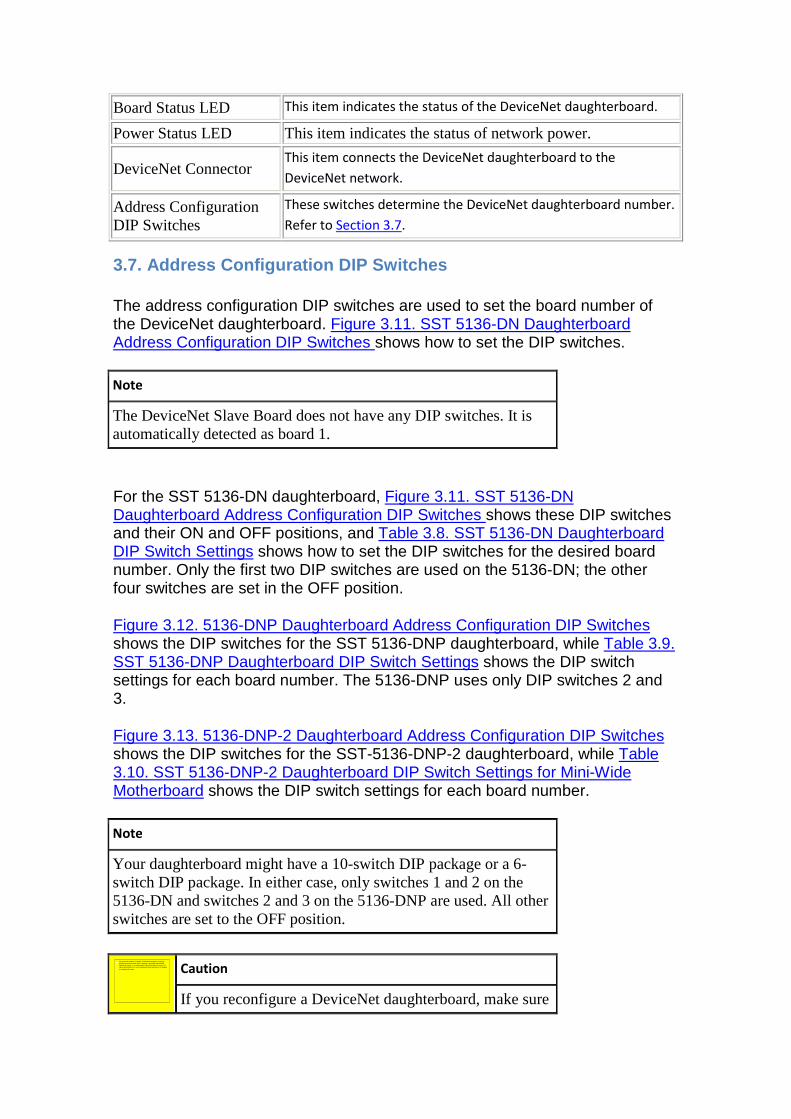
Board Status LED This item indicates the status of the DeviceNet daughterboard.
Power Status LED This item indicates the status of network power.
DeviceNet Connector This item connects the DeviceNet daughterboard to the
DeviceNet network.
Address Configuration DIP Switches
These switches determine the DeviceNet daughterboard number.
Refer to Section 3.7.
3.7. Address Configuration DIP Switches
The address configuration DIP switches are used to set the board number of the DeviceNet daughterboard. Figure 3.11. SST 5136-DN Daughterboard Address Configuration DIP Switches shows how to set the DIP switches.
Note
The DeviceNet Slave Board does not have any DIP switches. It is automatically detected as board 1.
For the SST 5136-DN daughterboard, Figure 3.11. SST 5136-DN Daughterboard Address Configuration DIP Switches shows these DIP switches and their ON and OFF positions, and Table 3.8. SST 5136-DN Daughterboard DIP Switch Settings shows how to set the DIP switches for the desired board number. Only the first two DIP switches are used on the 5136-DN; the other four switches are set in the OFF position.
Figure 3.12. 5136-DNP Daughterboard Address Configuration DIP Switches shows the DIP switches for the SST 5136-DNP daughterboard, while Table 3.9. SST 5136-DNP Daughterboard DIP Switch Settings shows the DIP switch settings for each board number. The 5136-DNP uses only DIP switches 2 and 3.
Figure 3.13. 5136-DNP-2 Daughterboard Address Configuration DIP Switches shows the DIP switches for the SST-5136-DNP-2 daughterboard, while Table 3.10. SST 5136-DNP-2 Daughterboard DIP Switch Settings for Mini-Wide Motherboard shows the DIP switch settings for each board number.
Note
Your daughterboard might have a 10-switch DIP package or a 6-switch DIP package. In either case, only switches 1 and 2 on the 5136-DN and switches 2 and 3 on the 5136-DNP are used. All other switches are set to the OFF position.
Caution
If you reconfigure a DeviceNet daughterboard, make sure
No se puede mostrar la imagen. Puede que su equipo no tenga suficiente memoria para abrir la imagen o que ésta esté dañada. Reinicie el equipo y, a continuación, abra el archivo de nuevo. Si sigue apareciendo la x roja, puede que tenga que borrar la imagen
e insertarla de nuevo.
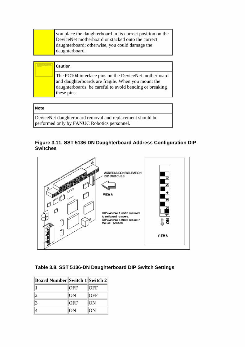
you place the daughterboard in its correct position on the DeviceNet motherboard or stacked onto the correct daughterboard; otherwise, you could damage the daughterboard.
Caution
The PC104 interface pins on the DeviceNet motherboard and daughterboards are fragile. When you mount the daughterboards, be careful to avoid bending or breaking these pins.
Note
DeviceNet daughterboard removal and replacement should be performed only by FANUC Robotics personnel.
Figure 3.11. SST 5136-DN Daughterboard Address Conf iguration DIP Switches
Table 3.8. SST 5136-DN Daughterboard DIP Switch Set tings
Board Number Switch 1 Switch 2
1 OFF OFF
2 ON OFF
3 OFF ON
4 ON ON
No se puede mostrar la imagen. Puede que su equipo no tenga suficiente memoria para abrir la imagen o que ésta esté dañada. Reinicie el equipo y, a continuación, abra el archivo de nuevo. Si sigue apareciendo la x roja, puede que tenga que borrar la imagen e insertarla de nuevo.
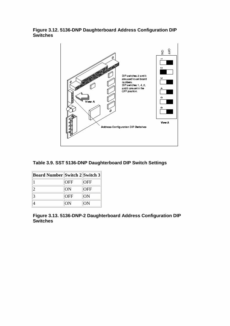
Figure 3.12. 5136-DNP Daughterboard Address Configu ration DIP Switches
Table 3.9. SST 5136-DNP Daughterboard DIP Switch Se ttings
Board Number Switch 2 Switch 3
1 OFF OFF
2 ON OFF
3 OFF ON
4 ON ON
Figure 3.13. 5136-DNP-2 Daughterboard Address Confi guration DIP Switches
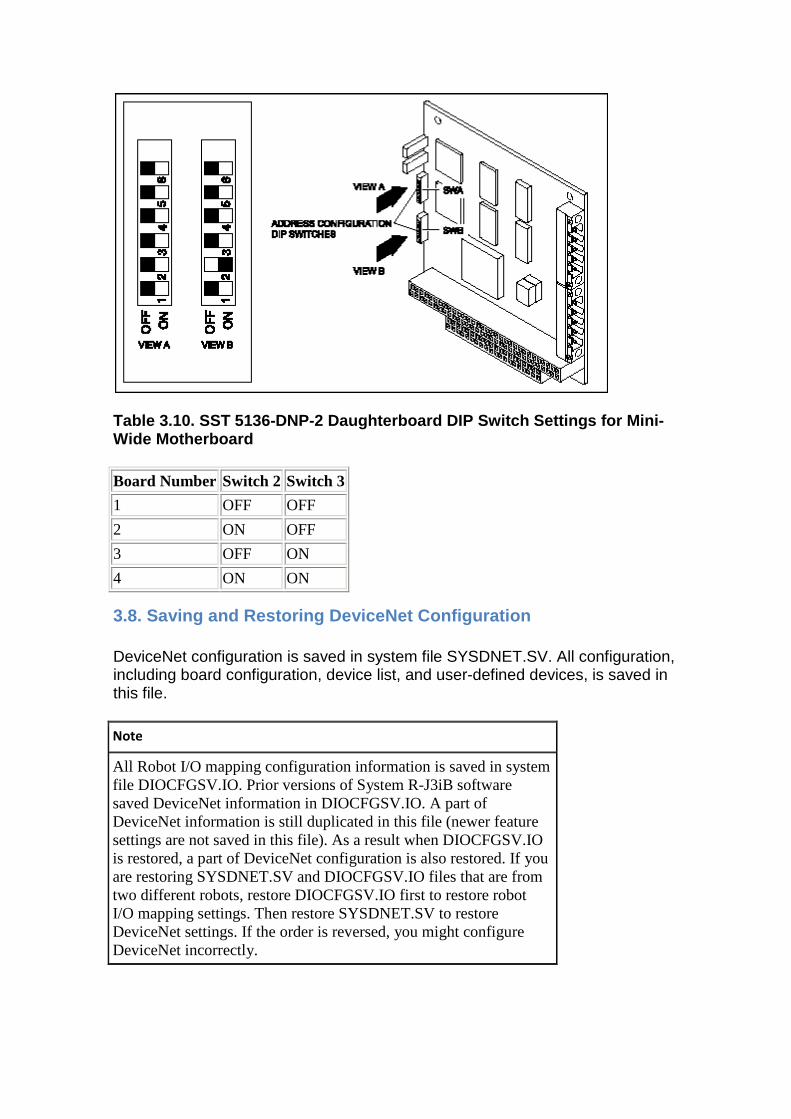
Table 3.10. SST 5136-DNP-2 Daughterboard DIP Switch Settings for Mini-Wide Motherboard
Board Number Switch 2 Switch 3
1 OFF OFF
2 ON OFF
3 OFF ON
4 ON ON
3.8. Saving and Restoring DeviceNet Configuration
DeviceNet configuration is saved in system file SYSDNET.SV. All configuration, including board configuration, device list, and user-defined devices, is saved in this file.
Note
All Robot I/O mapping configuration information is saved in system file DIOCFGSV.IO. Prior versions of System R-J3iB software saved DeviceNet information in DIOCFGSV.IO. A part of DeviceNet information is still duplicated in this file (newer feature settings are not saved in this file). As a result when DIOCFGSV.IO is restored, a part of DeviceNet configuration is also restored. If you are restoring SYSDNET.SV and DIOCFGSV.IO files that are from two different robots, restore DIOCFGSV.IO first to restore robot I/O mapping settings. Then restore SYSDNET.SV to restore DeviceNet settings. If the order is reversed, you might configure DeviceNet incorrectly.
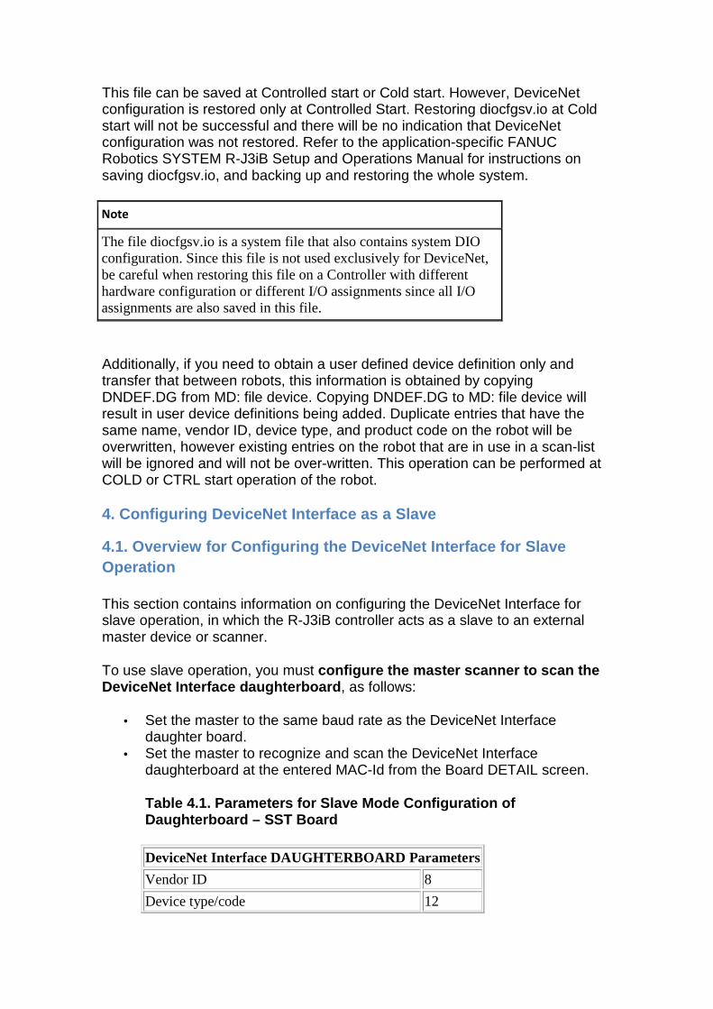
This file can be saved at Controlled start or Cold start. However, DeviceNet configuration is restored only at Controlled Start. Restoring diocfgsv.io at Cold start will not be successful and there will be no indication that DeviceNet configuration was not restored. Refer to the application-specific FANUC Robotics SYSTEM R-J3iB Setup and Operations Manual for instructions on saving diocfgsv.io, and backing up and restoring the whole system.
Note
The file diocfgsv.io is a system file that also contains system DIO configuration. Since this file is not used exclusively for DeviceNet, be careful when restoring this file on a Controller with different hardware configuration or different I/O assignments since all I/O assignments are also saved in this file.
Additionally, if you need to obtain a user defined device definition only and transfer that between robots, this information is obtained by copying DNDEF.DG from MD: file device. Copying DNDEF.DG to MD: file device will result in user device definitions being added. Duplicate entries that have the same name, vendor ID, device type, and product code on the robot will be overwritten, however existing entries on the robot that are in use in a scan-list will be ignored and will not be over-written. This operation can be performed at COLD or CTRL start operation of the robot.
4. Configuring DeviceNet Interface as a Slave
4.1. Overview for Configuring the DeviceNet Interfa ce for Slave Operation
This section contains information on configuring the DeviceNet Interface for slave operation, in which the R-J3iB controller acts as a slave to an external master device or scanner.
To use slave operation, you must configure the master scanner to scan the DeviceNet Interface daughterboard , as follows:
• Set the master to the same baud rate as the DeviceNet Interface daughter board.
• Set the master to recognize and scan the DeviceNet Interface daughterboard at the entered MAC-Id from the Board DETAIL screen.
Table 4.1. Parameters for Slave Mode Configuration of Daughterboard – SST Board
DeviceNet Interface DAUGHTERBOARD Parameters
Vendor ID 8
Device type/code 12
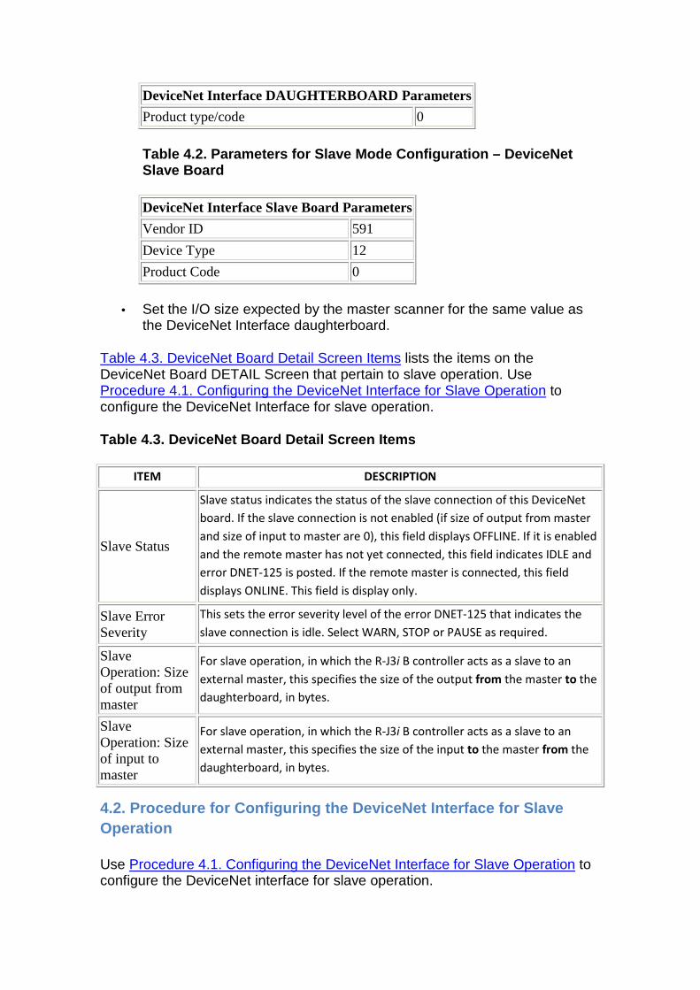
DeviceNet Interface DAUGHTERBOARD Parameters
Product type/code 0
Table 4.2. Parameters for Slave Mode Configuration – DeviceNet Slave Board
DeviceNet Interface Slave Board Parameters
Vendor ID 591
Device Type 12
Product Code 0
• Set the I/O size expected by the master scanner for the same value as the DeviceNet Interface daughterboard.
Table 4.3. DeviceNet Board Detail Screen Items lists the items on the DeviceNet Board DETAIL Screen that pertain to slave operation. Use Procedure 4.1. Configuring the DeviceNet Interface for Slave Operation to configure the DeviceNet Interface for slave operation.
Table 4.3. DeviceNet Board Detail Screen Items
ITEM DESCRIPTION
Slave Status
Slave status indicates the status of the slave connection of this DeviceNet
board. If the slave connection is not enabled (if size of output from master
and size of input to master are 0), this field displays OFFLINE. If it is enabled
and the remote master has not yet connected, this field indicates IDLE and
error DNET-125 is posted. If the remote master is connected, this field
displays ONLINE. This field is display only.
Slave Error Severity
This sets the error severity level of the error DNET-125 that indicates the
slave connection is idle. Select WARN, STOP or PAUSE as required.
Slave Operation: Size of output from master
For slave operation, in which the R-J3i B controller acts as a slave to an
external master, this specifies the size of the output from the master to the
daughterboard, in bytes.
Slave Operation: Size of input to master
For slave operation, in which the R-J3i B controller acts as a slave to an
external master, this specifies the size of the input to the master from the
daughterboard, in bytes.
4.2. Procedure for Configuring the DeviceNet Interf ace for Slave Operation
Use Procedure 4.1. Configuring the DeviceNet Interface for Slave Operation to configure the DeviceNet interface for slave operation.
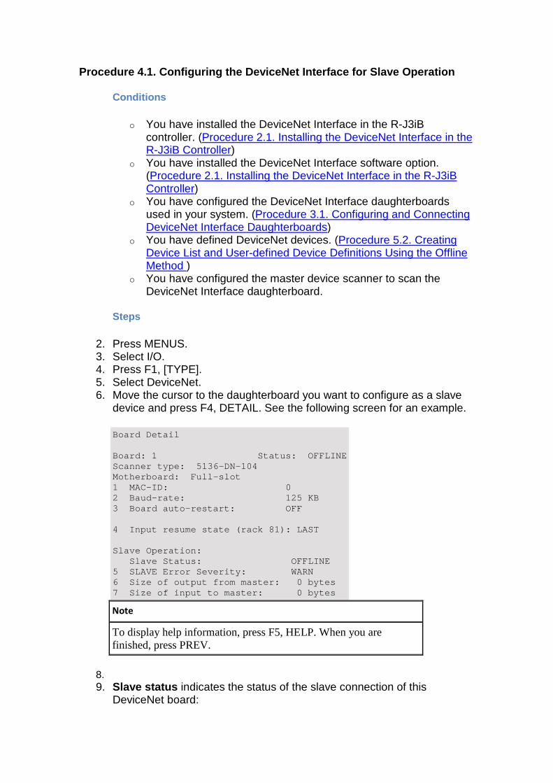
Procedure 4.1. Configuring the DeviceNet Interface for Slave Operation
Conditions
o You have installed the DeviceNet Interface in the R-J3iB controller. (Procedure 2.1. Installing the DeviceNet Interface in the R-J3iB Controller)
o You have installed the DeviceNet Interface software option. (Procedure 2.1. Installing the DeviceNet Interface in the R-J3iB Controller)
o You have configured the DeviceNet Interface daughterboards used in your system. (Procedure 3.1. Configuring and Connecting DeviceNet Interface Daughterboards)
o You have defined DeviceNet devices. (Procedure 5.2. Creating Device List and User-defined Device Definitions Using the Offline Method )
o You have configured the master device scanner to scan the DeviceNet Interface daughterboard.
Steps
2. Press MENUS. 3. Select I/O. 4. Press F1, [TYPE]. 5. Select DeviceNet. 6. Move the cursor to the daughterboard you want to configure as a slave
device and press F4, DETAIL. See the following screen for an example.
Board Detail Board: 1 Status: OFFLINE Scanner type: 5136-DN-104 Motherboard: Full-slot 1 MAC-ID: 0 2 Baud-rate: 125 KB 3 Board auto-restart: OFF 4 Input resume state (rack 81): LAST Slave Operation: Slave Status: OFFLINE 5 SLAVE Error Severity: WARN 6 Size of output from master: 0 bytes 7 Size of input to master: 0 bytes
Note
To display help information, press F5, HELP. When you are finished, press PREV.
8. 9. Slave status indicates the status of the slave connection of this
DeviceNet board:
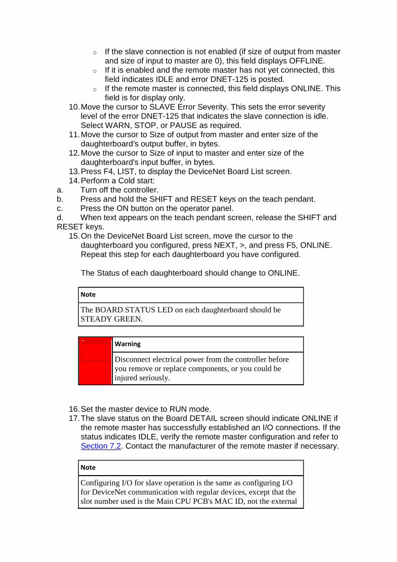
o If the slave connection is not enabled (if size of output from master and size of input to master are 0), this field displays OFFLINE.
o If it is enabled and the remote master has not yet connected, this field indicates IDLE and error DNET-125 is posted.
o If the remote master is connected, this field displays ONLINE. This field is for display only.
10. Move the cursor to SLAVE Error Severity. This sets the error severity level of the error DNET-125 that indicates the slave connection is idle. Select WARN, STOP, or PAUSE as required.
11. Move the cursor to Size of output from master and enter size of the daughterboard's output buffer, in bytes.
12. Move the cursor to Size of input to master and enter size of the daughterboard's input buffer, in bytes.
13. Press F4, LIST, to display the DeviceNet Board List screen. 14. Perform a Cold start:
a. Turn off the controller. b. Press and hold the SHIFT and RESET keys on the teach pendant. c. Press the ON button on the operator panel. d. When text appears on the teach pendant screen, release the SHIFT and RESET keys.
15. On the DeviceNet Board List screen, move the cursor to the daughterboard you configured, press NEXT, >, and press F5, ONLINE. Repeat this step for each daughterboard you have configured.
The Status of each daughterboard should change to ONLINE.
Note
The BOARD STATUS LED on each daughterboard should be STEADY GREEN.
Warning
Disconnect electrical power from the controller before you remove or replace components, or you could be injured seriously.
16. Set the master device to RUN mode. 17. The slave status on the Board DETAIL screen should indicate ONLINE if
the remote master has successfully established an I/O connections. If the status indicates IDLE, verify the remote master configuration and refer to Section 7.2. Contact the manufacturer of the remote master if necessary.
Note
Configuring I/O for slave operation is the same as configuring I/O for DeviceNet communication with regular devices, except that the slot number used is the Main CPU PCB's MAC ID, not the external
No se puede mostrar la imagen. Puede que su equipo no tenga suficiente memoria para abrir la imagen o que ésta esté dañada.
Reinicie el equipo y, a continuación, abra el archivo de nuevo. Si sigue apareciendo la x roja, puede que tenga que borrar la imagen e insertarla de nuevo.
master's MAC ID. The rack number used is the rack number shown on the Board List Screen.
18.
5. Configuring the DeviceNet Interface as a Master
A DeviceNet master (also known as a "Scanner") scans devices and exchanges I/O data with slave devices. Each R-J3iB DeviceNet master has a scan-list that indicates which devices it should scan. Section 5.1 describes how to create a scan-list or a device-list so that the master can exchange I/O with desired devices.
Note
DeviceNet Slave Mini F-bus board cannot be configured as a master.
5.1. Creating a Device List for each DeviceNet Daug hterboard to be configured as Master
You can use two methods to create the device list and add user-created device definitions:
• Online method with minimal information required from the user • Offline method with all information provided by the user
The online method for creating device lists and device definitions queries the device itself for most of the information. You are required to enter information that is not provided by the device (not specified by the DeviceNet protocol). This information typically can be obtained from the device datasheet provided by the manufacturer. This method requires that you have the physical devices connected to the network and your network installed correctly to allow DeviceNet to operate.
The offline method requires you to obtain all information and enter it using the teach pendant.
5.1.1. Online Method for Creating Device List and U ser-defined Device Defintions
Verify that you have the physical device connected to the DeviceNet network. If the MAC ID is set using dip switches, set the correct MAC ID and the baud-rate. Make sure that the robot DeviceNet interface card is connected to the DeviceNet network. Also verify that your DeviceNet network is installed correctly (check power, termination, connections, and so forth). If you have any other configuration tools or DeviceNet masters on the network, make sure they are not communicating with the remote device that you are trying to configure. Use Procedure 5.1. Creating Device List and User-defined Device Definitions Using
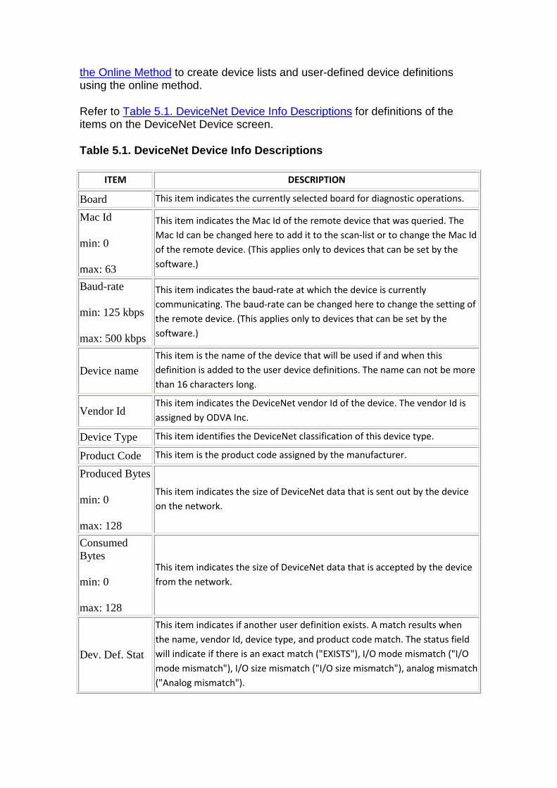
the Online Method to create device lists and user-defined device definitions using the online method.
Refer to Table 5.1. DeviceNet Device Info Descriptions for definitions of the items on the DeviceNet Device screen.
Table 5.1. DeviceNet Device Info Descriptions
ITEM DESCRIPTION
Board This item indicates the currently selected board for diagnostic operations.
Mac Id
min: 0
max: 63
This item indicates the Mac Id of the remote device that was queried. The
Mac Id can be changed here to add it to the scan-list or to change the Mac Id
of the remote device. (This applies only to devices that can be set by the
software.)
Baud-rate
min: 125 kbps
max: 500 kbps
This item indicates the baud-rate at which the device is currently
communicating. The baud-rate can be changed here to change the setting of
the remote device. (This applies only to devices that can be set by the
software.)
Device name This item is the name of the device that will be used if and when this
definition is added to the user device definitions. The name can not be more
than 16 characters long.
Vendor Id This item indicates the DeviceNet vendor Id of the device. The vendor Id is
assigned by ODVA Inc.
Device Type This item identifies the DeviceNet classification of this device type.
Product Code This item is the product code assigned by the manufacturer.
Produced Bytes
min: 0
max: 128
This item indicates the size of DeviceNet data that is sent out by the device
on the network.
Consumed Bytes
min: 0
max: 128
This item indicates the size of DeviceNet data that is accepted by the device
from the network.
Dev. Def. Stat
This item indicates if another user definition exists. A match results when
the name, vendor Id, device type, and product code match. The status field
will indicate if there is an exact match ("EXISTS"), I/O mode mismatch ("I/O
mode mismatch"), I/O size mismatch ("I/O size mismatch"), analog mismatch
("Analog mismatch").
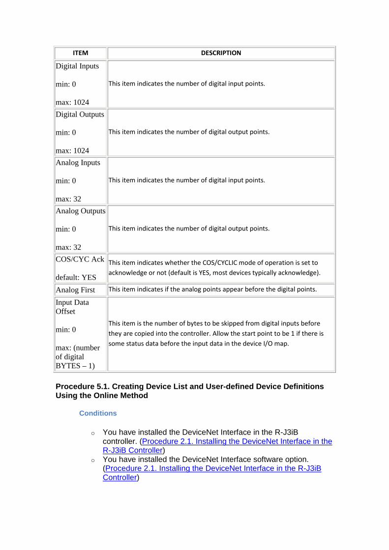
ITEM DESCRIPTION
Digital Inputs
min: 0
max: 1024
This item indicates the number of digital input points.
Digital Outputs
min: 0
max: 1024
This item indicates the number of digital output points.
Analog Inputs
min: 0
max: 32
This item indicates the number of digital input points.
Analog Outputs
min: 0
max: 32
This item indicates the number of digital output points.
COS/CYC Ack
default: YES
This item indicates whether the COS/CYCLIC mode of operation is set to
acknowledge or not (default is YES, most devices typically acknowledge).
Analog First This item indicates if the analog points appear before the digital points.
Input Data Offset
min: 0
max: (number of digital BYTES – 1)
This item is the number of bytes to be skipped from digital inputs before
they are copied into the controller. Allow the start point to be 1 if there is
some status data before the input data in the device I/O map.
Procedure 5.1. Creating Device List and User-define d Device Definitions Using the Online Method
Conditions
o You have installed the DeviceNet Interface in the R-J3iB controller. (Procedure 2.1. Installing the DeviceNet Interface in the R-J3iB Controller)
o You have installed the DeviceNet Interface software option. (Procedure 2.1. Installing the DeviceNet Interface in the R-J3iB Controller)
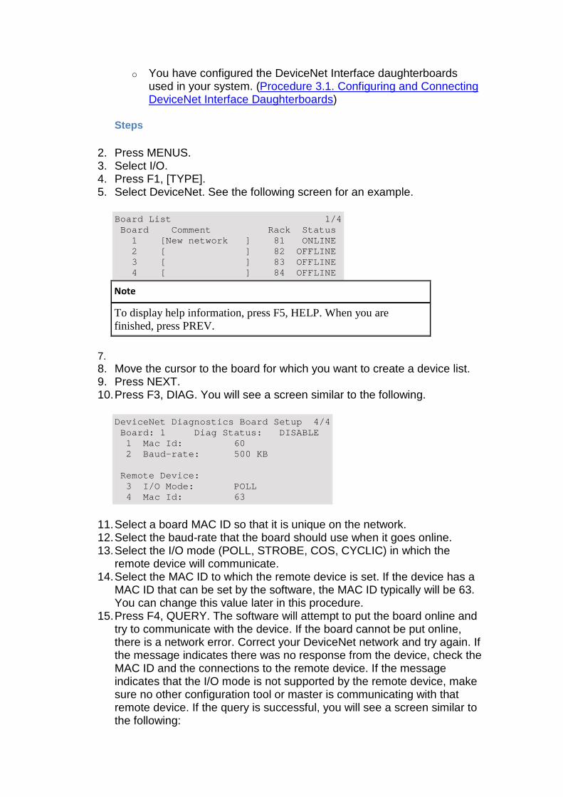
o You have configured the DeviceNet Interface daughterboards used in your system. (Procedure 3.1. Configuring and Connecting DeviceNet Interface Daughterboards)
Steps
2. Press MENUS. 3. Select I/O. 4. Press F1, [TYPE]. 5. Select DeviceNet. See the following screen for an example.
Board List 1/4 Board Comment Rack Status 1 [New network ] 81 ONLINE 2 [ ] 82 OFFLINE 3 [ ] 83 OFFLINE 4 [ ] 84 OFFLINE
Note
To display help information, press F5, HELP. When you are finished, press PREV.
7. 8. Move the cursor to the board for which you want to create a device list. 9. Press NEXT. 10. Press F3, DIAG. You will see a screen similar to the following.
DeviceNet Diagnostics Board Setup 4/4 Board: 1 Diag Status: DISABLE 1 Mac Id: 60 2 Baud- rate: 500 KB Remote Device: 3 I/O Mode: POLL 4 Mac Id: 63
11. Select a board MAC ID so that it is unique on the network. 12. Select the baud-rate that the board should use when it goes online. 13. Select the I/O mode (POLL, STROBE, COS, CYCLIC) in which the
remote device will communicate. 14. Select the MAC ID to which the remote device is set. If the device has a
MAC ID that can be set by the software, the MAC ID typically will be 63. You can change this value later in this procedure.
15. Press F4, QUERY. The software will attempt to put the board online and try to communicate with the device. If the board cannot be put online, there is a network error. Correct your DeviceNet network and try again. If the message indicates there was no response from the device, check the MAC ID and the connections to the remote device. If the message indicates that the I/O mode is not supported by the remote device, make sure no other configuration tool or master is communicating with that remote device. If the query is successful, you will see a screen similar to the following:
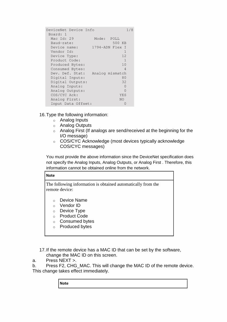
DeviceNet Device Info 1/8 Board: 1 Mac Id: 29 Mode: POLL Baud-rate: 500 KB Device name: 1794-ADN Flex I Vendor Id: 1 Devi ce Type: 12 Product Code: 1 Produced Bytes: 10 Consumed Bytes: 4 Dev. Def. Stat: Analog mismatch Digital Inputs: 80 Digital Outputs: 32 Analog Inputs: 0 Analog Outputs: 0 COS/CYC Ack: YES Analog First: NO Input Data Offset: 0
16. Type the following information: o Analog Inputs o Analog Outputs o Analog First (If analogs are send/received at the beginning for the
I/O message) o COS/CYC Acknowledge (most devices typically acknowledge
COS/CYC messages)
You must provide the above information since the DeviceNet specification does not specify the Analog Inputs, Analog Outputs, or Analog First . Therefore, this information cannot be obtained online from the network.
Note
The following information is obtained automatically from the remote device:
o Device Name o Vendor ID o Device Type o Product Code o Consumed bytes o Produced bytes
17. If the remote device has a MAC ID that can be set by the software, change the MAC ID on this screen.
a. Press NEXT >. b. Press F2, CHG_MAC. This will change the MAC ID of the remote device. This change takes effect immediately.
Note
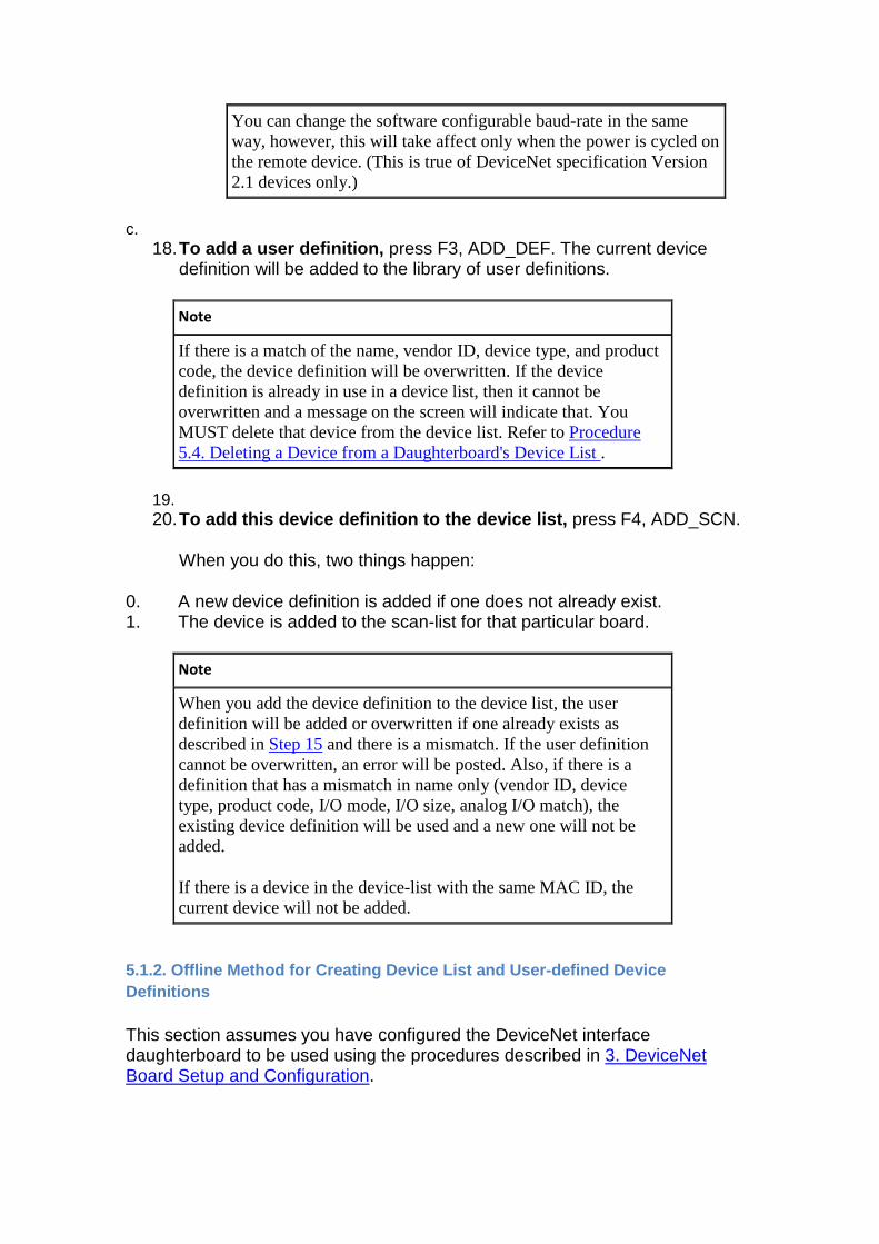
You can change the software configurable baud-rate in the same way, however, this will take affect only when the power is cycled on the remote device. (This is true of DeviceNet specification Version 2.1 devices only.)
c. 18. To add a user definition, press F3, ADD_DEF. The current device
definition will be added to the library of user definitions.
Note
If there is a match of the name, vendor ID, device type, and product code, the device definition will be overwritten. If the device definition is already in use in a device list, then it cannot be overwritten and a message on the screen will indicate that. You MUST delete that device from the device list. Refer to Procedure 5.4. Deleting a Device from a Daughterboard's Device List .
19. 20. To add this device definition to the device list, press F4, ADD_SCN.
When you do this, two things happen:
0. A new device definition is added if one does not already exist. 1. The device is added to the scan-list for that particular board.
Note
When you add the device definition to the device list, the user definition will be added or overwritten if one already exists as described in Step 15 and there is a mismatch. If the user definition cannot be overwritten, an error will be posted. Also, if there is a definition that has a mismatch in name only (vendor ID, device type, product code, I/O mode, I/O size, analog I/O match), the existing device definition will be used and a new one will not be added.
If there is a device in the device-list with the same MAC ID, the current device will not be added.
5.1.2. Offline Method for Creating Device List and User-defined Device Definitions
This section assumes you have configured the DeviceNet interface daughterboard to be used using the procedures described in 3. DeviceNet Board Setup and Configuration.
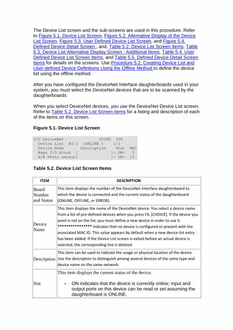
The Device List screen and the sub-screens are used in this procedure. Refer to Figure 5.1. Device List Screen, Figure 5.2. Alternative Display of the Device List Screen, Figure 5.3. User Defined Device List Screen, and Figure 5.4. Defined Device Detail Screen , and, Table 5.2. Device List Screen Items, Table 5.3. Device List Alternative Display Screen - Additional Items, Table 5.4. User Defined Device List Screen Items, and Table 5.5. Defined Device Detail Screen Items for details on the screens. Use Procedure 5.2. Creating Device List and User-defined Device Definitions Using the Offline Method to define the device list using the offline method.
After you have configured the DeviceNet Interface daughterboards used in your system, you must select the DeviceNet devices that are to be scanned by the daughterboards.
When you select DeviceNet devices, you use the DeviceNet Device List screen. Refer to Table 5.2. Device List Screen Items for a listing and description of each of the items on this screen.
Figure 5.1. Device List Screen
I/O DeviceNet JOINT 10% Device List Bd 2 (ONLINE ) 1/2 Device Name Description Stat MAC Wago I/O Block [ ]< ON> 3 A/B Photo sensor[ ]< ON> 10
Table 5.2. Device List Screen Items
ITEM DESCRIPTION
Board Number and Status
This item displays the number of the DeviceNet Interface daughterboard to
which the device is connected and the current status of the daughterboard
(ONLINE, OFFLINE, or ERROR).
Device Name
This item displays the name of the DeviceNet device. You select a device name
from a list of pre-defined devices when you press F4, [CHOICE]. If the device you
want is not on the list, you must define a new device in order to use it.
**************** indicates that no device is configured or present with the
associated MAC ID. This value appears by default when a new device-list entry
has been added. If the Device List screen is exited before an actual device is
selected, the corresponding line is deleted.
Description
This item can be used to indicate the usage or physical location of the device.
Use the description to distinguish among several devices of the same type and
device name on the same network.
Stat
This item displays the current status of the device.
• ON indicates that the device is currently online; input and output ports on this device can be read or set assuming the daughterboard is ONLINE.
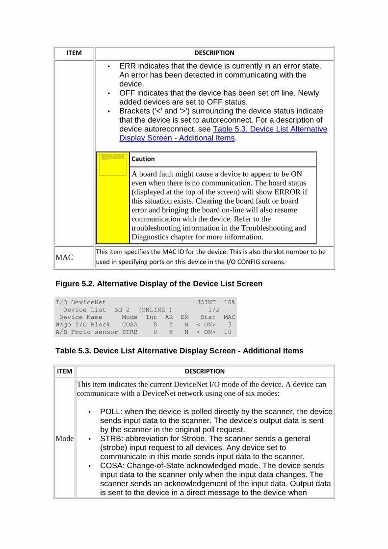
ITEM DESCRIPTION
• ERR indicates that the device is currently in an error state. An error has been detected in communicating with the device.
• OFF indicates that the device has been set off line. Newly added devices are set to OFF status.
• Brackets ('<' and '>') surrounding the device status indicate that the device is set to autoreconnect. For a description of device autoreconnect, see Table 5.3. Device List Alternative Display Screen - Additional Items.
Caution
A board fault might cause a device to appear to be ON even when there is no communication. The board status (displayed at the top of the screen) will show ERROR if this situation exists. Clearing the board fault or board error and bringing the board on-line will also resume communication with the device. Refer to the troubleshooting information in the Troubleshooting and Diagnostics chapter for more information.
MAC This item specifies the MAC ID for the device. This is also the slot number to be
used in specifying ports on this device in the I/O CONFIG screens.
Figure 5.2. Alternative Display of the Device List Screen
I/O DeviceNet JOINT 10% Device List Bd 2 (ONLINE ) 1/2 Device Name Mode Int AR EM Stat MAC Wago I/O Block COSA 0 Y N < ON> 3 A/B Photo sensor STRB 0 Y N < ON> 10
Table 5.3. Device List Alternative Display Screen - Additional Items
ITEM DESCRIPTION
Mode
This item indicates the current DeviceNet I/O mode of the device. A device can communicate with a DeviceNet network using one of six modes:
• POLL: when the device is polled directly by the scanner, the device sends input data to the scanner. The device's output data is sent by the scanner in the original poll request.
• STRB: abbreviation for Strobe. The scanner sends a general (strobe) input request to all devices. Any device set to communicate in this mode sends input data to the scanner.
• COSA: Change-of-State acknowledged mode. The device sends input data to the scanner only when the input data changes. The scanner sends an acknowledgement of the input data. Output data is sent to the device in a direct message to the device when
No se puede mostrar la imagen. Puede que su equipo no tenga suficiente memoria para abrir la imagen o que ésta esté dañada. Reinicie el equipo y, a continuación, abra el archivo de nuevo. Si sigue apareciendo la x roja, puede que tenga que borrar la imagen e insertarla de nuevo.
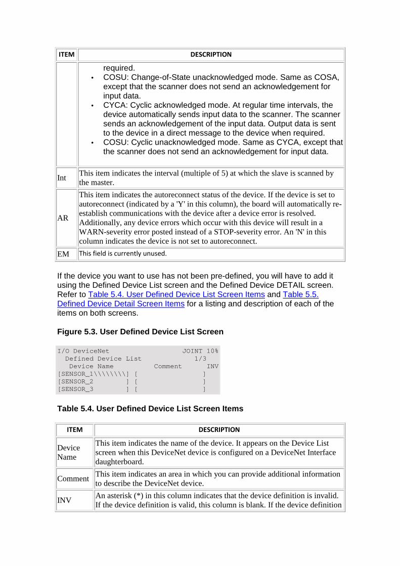
ITEM DESCRIPTION
required. • COSU: Change-of-State unacknowledged mode. Same as COSA,
except that the scanner does not send an acknowledgement for input data.
• CYCA: Cyclic acknowledged mode. At regular time intervals, the device automatically sends input data to the scanner. The scanner sends an acknowledgement of the input data. Output data is sent to the device in a direct message to the device when required.
• COSU: Cyclic unacknowledged mode. Same as CYCA, except that the scanner does not send an acknowledgement for input data.
Int This item indicates the interval (multiple of 5) at which the slave is scanned by the master.
AR
This item indicates the autoreconnect status of the device. If the device is set to autoreconnect (indicated by a 'Y' in this column), the board will automatically re-establish communications with the device after a device error is resolved. Additionally, any device errors which occur with this device will result in a WARN-severity error posted instead of a STOP-severity error. An 'N' in this column indicates the device is not set to autoreconnect.
EM This field is currently unused.
If the device you want to use has not been pre-defined, you will have to add it using the Defined Device List screen and the Defined Device DETAIL screen. Refer to Table 5.4. User Defined Device List Screen Items and Table 5.5. Defined Device Detail Screen Items for a listing and description of each of the items on both screens.
Figure 5.3. User Defined Device List Screen
I/O DeviceNet JOINT 10% Defined Device List 1/3 Device Name Comment INV [SENSOR_1\\\\\\\\] [ ] [SENSOR_2 ] [ ] [SENSOR_3 ] [ ]
Table 5.4. User Defined Device List Screen Items
ITEM DESCRIPTION
Device Name
This item indicates the name of the device. It appears on the Device List screen when this DeviceNet device is configured on a DeviceNet Interface daughterboard.
Comment This item indicates an area in which you can provide additional information to describe the DeviceNet device.
INV An asterisk (*) in this column indicates that the device definition is invalid. If the device definition is valid, this column is blank. If the device definition
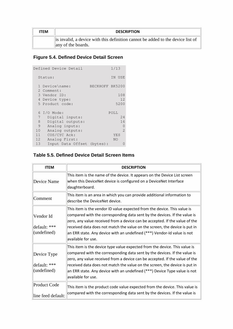
ITEM DESCRIPTION
is invalid, a device with this definition cannot be added to the device list of any of the boards.
Figure 5.4. Defined Device Detail Screen
Defined Device Detail 1/13 Status: IN USE 1 Device\name: BECKHOFF BK5200 2 Comment: 3 Vendor ID: 108 4 Device type: 12 5 Product code: 5200 6 I/O Mode: POLL 7 Digital inputs: 24 8 Digital outputs: 16 9 Analog inputs: 0 10 Analog outputs: 2 11 COS/CYC Ack: YES 12 Analog First: NO 13 Input Data Offset (bytes): 0
Table 5.5. Defined Device Detail Screen Items
ITEM DESCRIPTION
Device Name This item is the name of the device. It appears on the Device List screen
when this DeviceNet device is configured on a DeviceNet Interface
daughterboard.
Comment This item is an area in which you can provide additional information to
describe the DeviceNet device.
Vendor Id
default: *** (undefined)
This item is the vendor ID value expected from the device. This value is
compared with the corresponding data sent by the devices. If the value is
zero, any value received from a device can be accepted. If the value of the
received data does not match the value on the screen, the device is put in
an ERR state. Any device with an undefined (***) Vendor-Id value is not
available for use.
Device Type
default: *** (undefined)
This item is the device type value expected from the device. This value is
compared with the corresponding data sent by the devices. If the value is
zero, any value received from a device can be accepted. If the value of the
received data does not match the value on the screen, the device is put in
an ERR state. Any device with an undefined (***) Device Type value is not
available for use.
Product Code
line feed default:
This item is the product code value expected from the device. This value is
compared with the corresponding data sent by the devices. If the value is
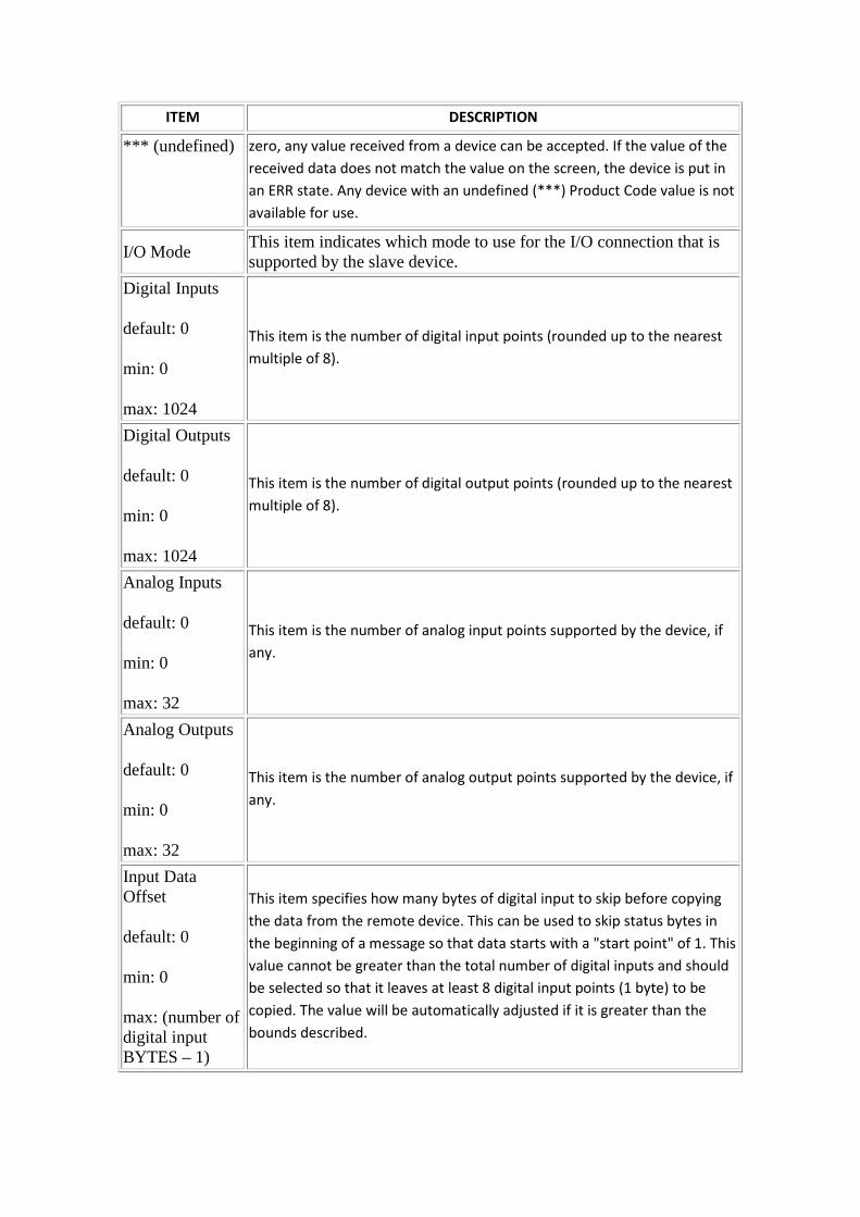
ITEM DESCRIPTION
*** (undefined) zero, any value received from a device can be accepted. If the value of the
received data does not match the value on the screen, the device is put in
an ERR state. Any device with an undefined (***) Product Code value is not
available for use.
I/O Mode This item indicates which mode to use for the I/O connection that is supported by the slave device.
Digital Inputs
default: 0
min: 0
max: 1024
This item is the number of digital input points (rounded up to the nearest
multiple of 8).
Digital Outputs
default: 0
min: 0
max: 1024
This item is the number of digital output points (rounded up to the nearest
multiple of 8).
Analog Inputs
default: 0
min: 0
max: 32
This item is the number of analog input points supported by the device, if
any.
Analog Outputs
default: 0
min: 0
max: 32
This item is the number of analog output points supported by the device, if
any.
Input Data Offset
default: 0
min: 0
max: (number of digital input BYTES – 1)
This item specifies how many bytes of digital input to skip before copying
the data from the remote device. This can be used to skip status bytes in
the beginning of a message so that data starts with a "start point" of 1. This
value cannot be greater than the total number of digital inputs and should
be selected so that it leaves at least 8 digital input points (1 byte) to be
copied. The value will be automatically adjusted if it is greater than the
bounds described.
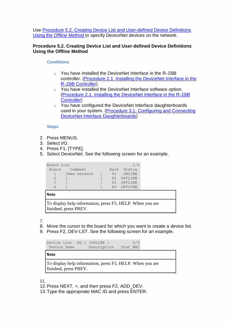
Use Procedure 5.2. Creating Device List and User-defined Device Definitions Using the Offline Method to specify DeviceNet devices on the network.
Procedure 5.2. Creating Device List and User-define d Device Definitions Using the Offline Method
Conditions
o You have installed the DeviceNet Interface in the R-J3iB controller. (Procedure 2.1. Installing the DeviceNet Interface in the R-J3iB Controller)
o You have installed the DeviceNet Interface software option. (Procedure 2.1. Installing the DeviceNet Interface in the R-J3iB Controller)
o You have configured the DeviceNet Interface daughterboards used in your system. (Procedure 3.1. Configuring and Connecting DeviceNet Interface Daughterboards)
Steps
2. Press MENUS. 3. Select I/O. 4. Press F1, [TYPE]. 5. Select DeviceNet. See the following screen for an example.
Board List 1/4 Board Comment Rack Status 1 [New network ] 81 ONLINE 2 [ ] 82 OFFLINE 3 [ ] 83 OFFLINE 4 [ ] 84 OFFLINE
Note
To display help information, press F5, HELP. When you are finished, press PREV.
7. 8. Move the cursor to the board for which you want to create a device list. 9. Press F2, DEV-LST. See the following screen for an example.
Device List Bd 1 (ONLINE ) 0/0 Device Name Description Stat MAC
Note
To display help information, press F5, HELP. When you are finished, press PREV.
11. 12. Press NEXT, >, and then press F2, ADD_DEV. 13. Type the appropriate MAC ID and press ENTER.
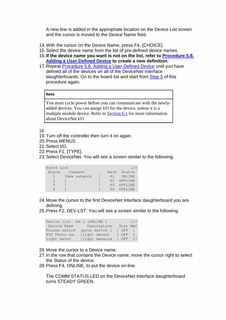
A new line is added in the appropriate location on the Device List screen and the cursor is moved to the Device Name field.
14. With the cursor on the Device Name, press F4, [CHOICE]. 15. Select the device name from the list of pre-defined device names. 16. If the device name you want is not on the list, ref er to Procedure 5.8.
Adding a User-Defined Device to create a new definition. 17. Repeat Procedure 5.8. Adding a User-Defined Device until you have
defined all of the devices on all of the DeviceNet Interface daughterboards. Go to the board list and start from Step 5 of this procedure again.
Note
You must cycle power before you can communicate with the newly-added devices. You can assign I/O for the device, unless it is a multiple module device. Refer to Section 6.1 for more information about DeviceNet I/O
18. 19. Turn off the controller then turn it on again. 20. Press MENUS. 21. Select I/O. 22. Press F1, [TYPE]. 23. Select DeviceNet. You will see a screen similar to the following.
Board List 1/4 Board Comment Rack Status 1 [New network ] 81 ONLINE 2 [ ] 82 OFFLINE 3 [ ] 83 OFFLINE 4 [ ] 84 OFFLINE
24. Move the cursor to the first DeviceNet Interface daughterboard you are defining.
25. Press F2, DEV-LST. You will see a screen similar to the following.
Device List Bd 1 (ONLINE ) 1/3 Device Name Description Stat MAC Proxim switch [prox switch 1 ] OFF 1 XYZ Photo sw. [light detect ] OFF 2 Light meter [light measure ] OFF 17
26. Move the cursor to a Device name. 27. In the row that contains the Device name, move the cursor right to select
the Status of the device. 28. Press F4, ONLINE, to put the device on-line.
The COMM STATUS LED on the DeviceNet Interface daughterboard turns STEADY GREEN.
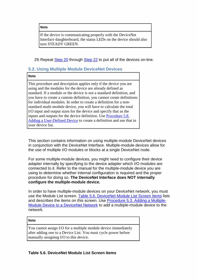
Note
If the device is communicating properly with the DeviceNet Interface daughterboard, the status LEDs on the device should also turn STEADY GREEN.
29. Repeat Step 20 through Step 22 to put all of the devices on-line.
5.2. Using Multiple Module DeviceNet Devices
Note
This procedure and description applies only if the device you are using and the modules for the device are already defined as standard. If a module or the device is not a standard definition, and you have to create a custom definition, you cannot create definitions for individual modules. In order to create a definition for a non-standard multi-module device, you will have to calculate the total I/O input and output sizes for the device and specify that as the inputs and outputs for the device definition. Use Procedure 5.8. Adding a User-Defined Device to create a definition and use that in your device list.
This section contains information on using multiple-module DeviceNet devices in conjunction with the DeviceNet Interface. Multiple-module devices allow for the use of multiple I/O modules or blocks at a single DeviceNet node.
For some multiple-module devices, you might need to configure their device adapter internally by specifying to the device adapter which I/O modules are connected to it. Refer to the manual for the multiple-module device you are using to determine whether internal configuration is required and the proper procedure for doing so. The DeviceNet Interface does NOT internally configure the multiple-module device.
In order to have multiple-module devices on your DeviceNet network, you must use the Module List screen. Table 5.6. DeviceNet Module List Screen Items lists and describes the items on this screen. Use Procedure 5.3. Adding a Multiple-Module Device to a DeviceNet Network to add a multiple-module device to the network.
Note
You cannot assign I/O for a multiple module device immediately after adding one to a Device List. You must cycle power before manually assigning I/O to this device.
Table 5.6. DeviceNet Module List Screen Items
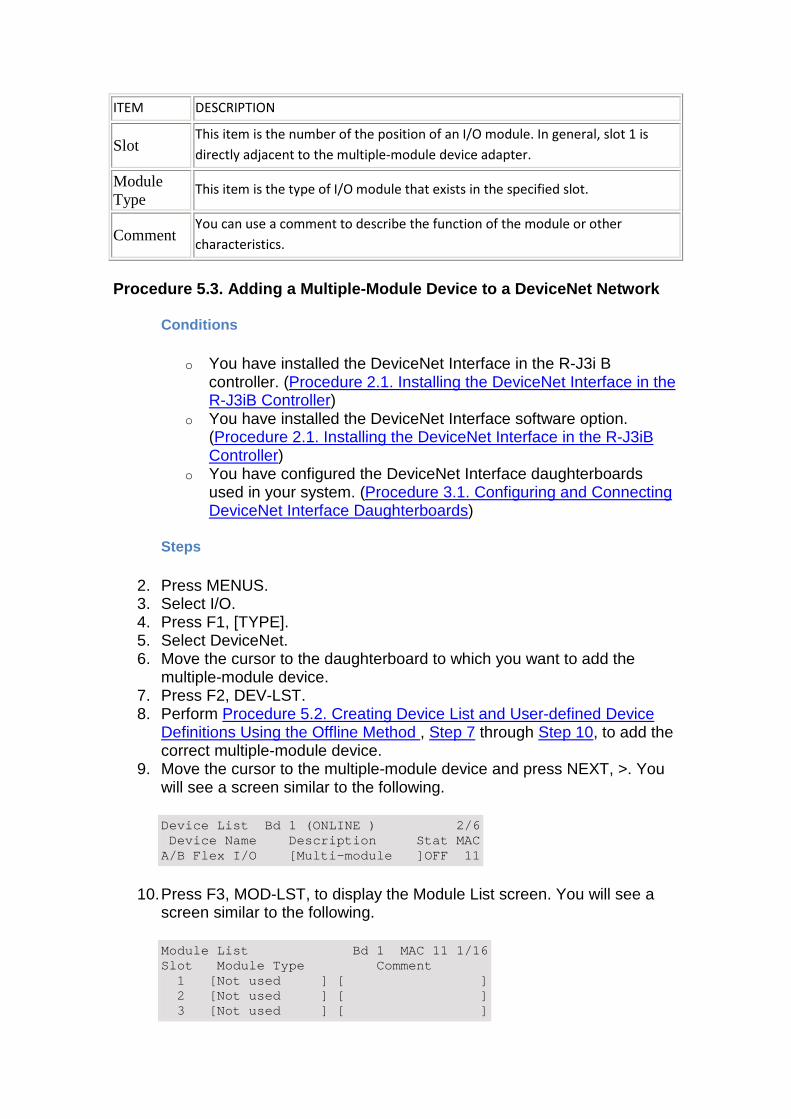
ITEM DESCRIPTION
Slot This item is the number of the position of an I/O module. In general, slot 1 is
directly adjacent to the multiple-module device adapter.
Module Type
This item is the type of I/O module that exists in the specified slot.
Comment You can use a comment to describe the function of the module or other
characteristics.
Procedure 5.3. Adding a Multiple-Module Device to a DeviceNet Network
Conditions
o You have installed the DeviceNet Interface in the R-J3i B controller. (Procedure 2.1. Installing the DeviceNet Interface in the R-J3iB Controller)
o You have installed the DeviceNet Interface software option. (Procedure 2.1. Installing the DeviceNet Interface in the R-J3iB Controller)
o You have configured the DeviceNet Interface daughterboards used in your system. (Procedure 3.1. Configuring and Connecting DeviceNet Interface Daughterboards)
Steps
2. Press MENUS. 3. Select I/O. 4. Press F1, [TYPE]. 5. Select DeviceNet. 6. Move the cursor to the daughterboard to which you want to add the
multiple-module device. 7. Press F2, DEV-LST. 8. Perform Procedure 5.2. Creating Device List and User-defined Device
Definitions Using the Offline Method , Step 7 through Step 10, to add the correct multiple-module device.
9. Move the cursor to the multiple-module device and press NEXT, >. You will see a screen similar to the following.
Device List Bd 1 (ONLINE ) 2/6 Device Name Description Stat MAC A/B Flex I/O [Multi-module ]OFF 11
10. Press F3, MOD-LST, to display the Module List screen. You will see a screen similar to the following.
Module List Bd 1 MAC 11 1/16 Slot Module Type Comment 1 [Not used ] [ ] 2 [Not used ] [ ] 3 [Not used ] [ ]
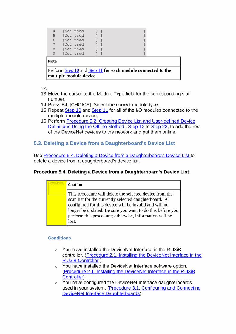
4 [Not used ] [ ] 5 [Not used ] [ ] 6 [Not used ] [ ] 7 [Not used ] [ ] 8 [Not used ] [ ] 9 [Not used ] [ ]
Note
Perform Step 10 and Step 11 for each module connected to the multiple-module device.
12. 13. Move the cursor to the Module Type field for the corresponding slot
number. 14. Press F4, [CHOICE]. Select the correct module type. 15. Repeat Step 10 and Step 11 for all of the I/O modules connected to the
multiple-module device. 16. Perform Procedure 5.2. Creating Device List and User-defined Device
Definitions Using the Offline Method , Step 12 to Step 22, to add the rest of the DeviceNet devices to the network and put them online.
5.3. Deleting a Device from a Daughterboard's Devic e List
Use Procedure 5.4. Deleting a Device from a Daughterboard's Device List to delete a device from a daughterboard's device list.
Procedure 5.4. Deleting a Device from a Daughterboa rd's Device List
Caution
This procedure will delete the selected device from the scan list for the currently selected daughterboard. I/O configured for this device will be invalid and will no longer be updated. Be sure you want to do this before you perform this procedure; otherwise, information will be lost.
Conditions
o You have installed the DeviceNet Interface in the R-J3iB controller. (Procedure 2.1. Installing the DeviceNet Interface in the R-J3iB Controller )
o You have installed the DeviceNet Interface software option. (Procedure 2.1. Installing the DeviceNet Interface in the R-J3iB Controller)
o You have configured the DeviceNet Interface daughterboards used in your system. (Procedure 3.1. Configuring and Connecting DeviceNet Interface Daughterboards)
No se puede mostrar la imagen. Puede que su equipo no tenga suficiente memoria para abrir la imagen o que ésta esté dañada. Reinicie el equipo y, a continuación, abra el archivo de nuevo. Si sigue apareciendo la x roja, puede que tenga que borrar la imagen e insertarla de nuevo.
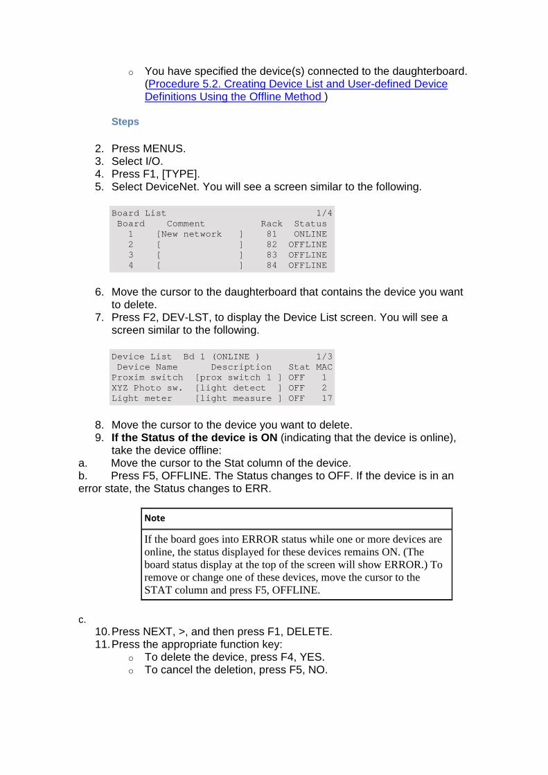
o You have specified the device(s) connected to the daughterboard. (Procedure 5.2. Creating Device List and User-defined Device Definitions Using the Offline Method )
Steps
2. Press MENUS. 3. Select I/O. 4. Press F1, [TYPE]. 5. Select DeviceNet. You will see a screen similar to the following.
Board List 1/4 Board Comment Rack Status 1 [New network ] 81 ONLINE 2 [ ] 82 OFFLINE 3 [ ] 83 OFFLINE 4 [ ] 84 OFFLINE
6. Move the cursor to the daughterboard that contains the device you want to delete.
7. Press F2, DEV-LST, to display the Device List screen. You will see a screen similar to the following.
Device List Bd 1 (ONLINE ) 1/3 Device Name Description Stat MAC Proxim switch [prox switch 1 ] OFF 1 XYZ Photo sw. [light detect ] OFF 2 Light meter [light measure ] OFF 17
8. Move the cursor to the device you want to delete. 9. If the Status of the device is ON (indicating that the device is online),
take the device offline: a. Move the cursor to the Stat column of the device. b. Press F5, OFFLINE. The Status changes to OFF. If the device is in an error state, the Status changes to ERR.
Note
If the board goes into ERROR status while one or more devices are online, the status displayed for these devices remains ON. (The board status display at the top of the screen will show ERROR.) To remove or change one of these devices, move the cursor to the STAT column and press F5, OFFLINE.
c. 10. Press NEXT, >, and then press F1, DELETE. 11. Press the appropriate function key:
o To delete the device, press F4, YES. o To cancel the deletion, press F5, NO.
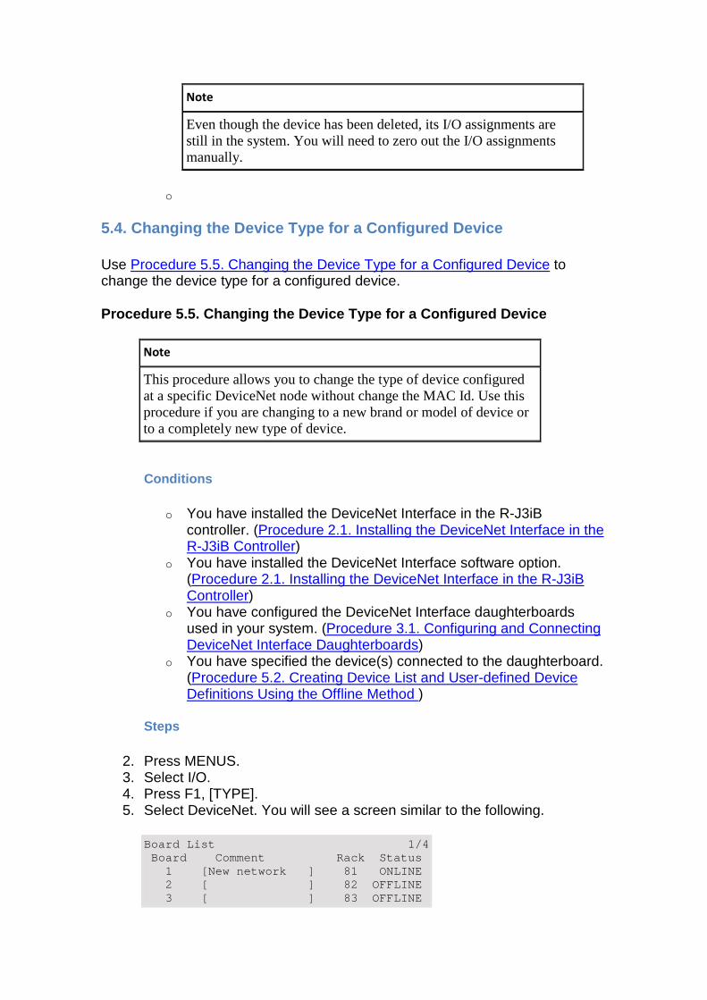
Note
Even though the device has been deleted, its I/O assignments are still in the system. You will need to zero out the I/O assignments manually.
o
5.4. Changing the Device Type for a Configured Devi ce
Use Procedure 5.5. Changing the Device Type for a Configured Device to change the device type for a configured device.
Procedure 5.5. Changing the Device Type for a Confi gured Device
Note
This procedure allows you to change the type of device configured at a specific DeviceNet node without change the MAC Id. Use this procedure if you are changing to a new brand or model of device or to a completely new type of device.
Conditions
o You have installed the DeviceNet Interface in the R-J3iB controller. (Procedure 2.1. Installing the DeviceNet Interface in the R-J3iB Controller)
o You have installed the DeviceNet Interface software option. (Procedure 2.1. Installing the DeviceNet Interface in the R-J3iB Controller)
o You have configured the DeviceNet Interface daughterboards used in your system. (Procedure 3.1. Configuring and Connecting DeviceNet Interface Daughterboards)
o You have specified the device(s) connected to the daughterboard. (Procedure 5.2. Creating Device List and User-defined Device Definitions Using the Offline Method )
Steps
2. Press MENUS. 3. Select I/O. 4. Press F1, [TYPE]. 5. Select DeviceNet. You will see a screen similar to the following.
Board List 1/4 Board Comment Rack Status 1 [New network ] 81 ONLINE 2 [ ] 82 OFFLINE 3 [ ] 83 OFFLINE
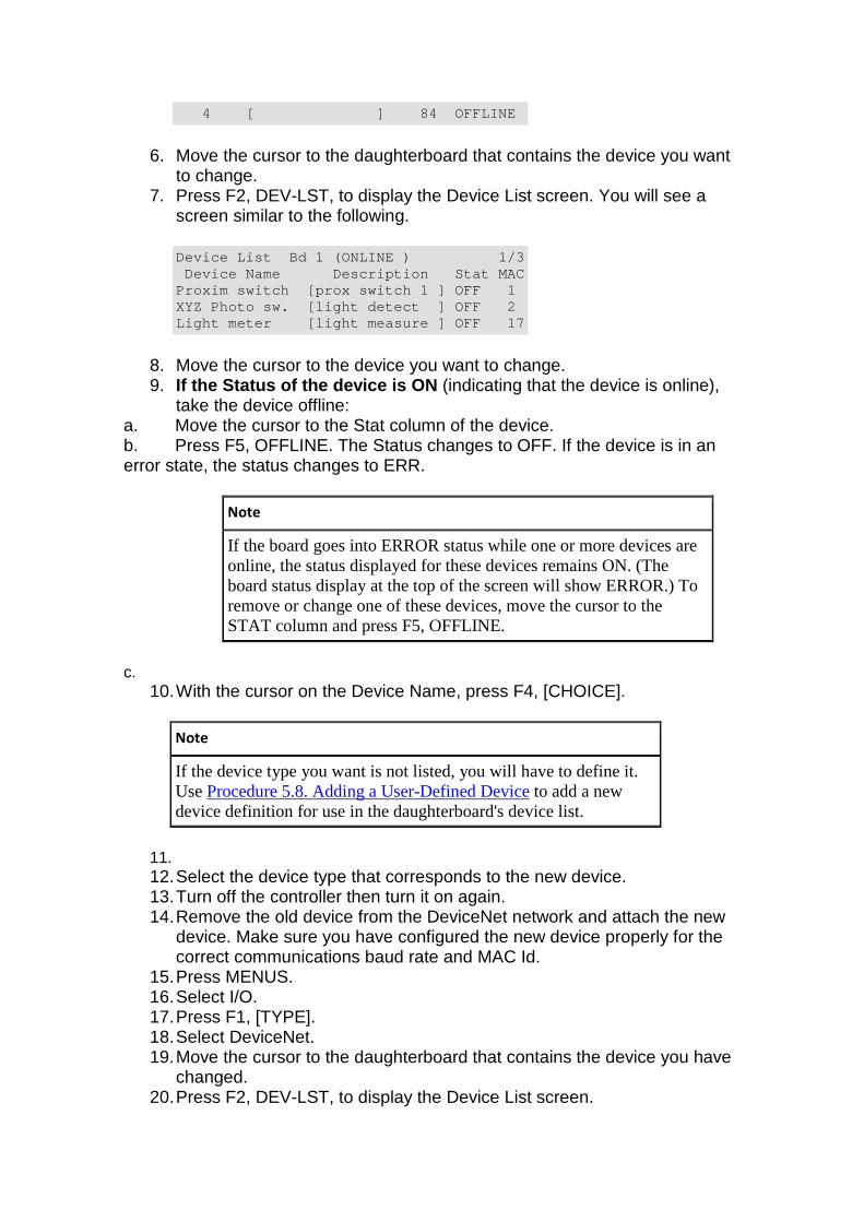
4 [ ] 84 OFFLINE
6. Move the cursor to the daughterboard that contains the device you want to change.
7. Press F2, DEV-LST, to display the Device List screen. You will see a screen similar to the following.
Device List Bd 1 (ONLINE ) 1/3 Device Name Description Stat MAC Proxim switch [prox switch 1 ] OFF 1 XYZ Photo sw. [light detect ] OFF 2 Light meter [light measure ] OFF 17
8. Move the cursor to the device you want to change. 9. If the Status of the device is ON (indicating that the device is online),
take the device offline: a. Move the cursor to the Stat column of the device. b. Press F5, OFFLINE. The Status changes to OFF. If the device is in an error state, the status changes to ERR.
Note
If the board goes into ERROR status while one or more devices are online, the status displayed for these devices remains ON. (The board status display at the top of the screen will show ERROR.) To remove or change one of these devices, move the cursor to the STAT column and press F5, OFFLINE.
c. 10. With the cursor on the Device Name, press F4, [CHOICE].
Note
If the device type you want is not listed, you will have to define it. Use Procedure 5.8. Adding a User-Defined Device to add a new device definition for use in the daughterboard's device list.
11. 12. Select the device type that corresponds to the new device. 13. Turn off the controller then turn it on again. 14. Remove the old device from the DeviceNet network and attach the new
device. Make sure you have configured the new device properly for the correct communications baud rate and MAC Id.
15. Press MENUS. 16. Select I/O. 17. Press F1, [TYPE]. 18. Select DeviceNet. 19. Move the cursor to the daughterboard that contains the device you have
changed. 20. Press F2, DEV-LST, to display the Device List screen.
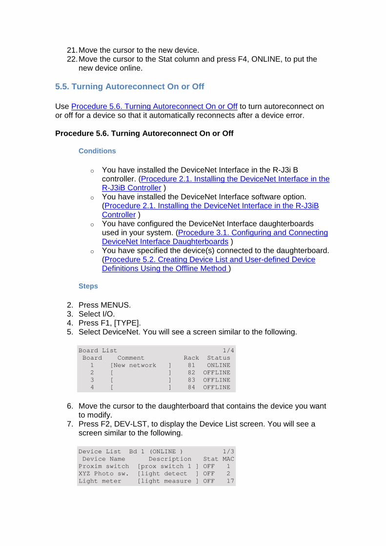
21. Move the cursor to the new device. 22. Move the cursor to the Stat column and press F4, ONLINE, to put the
new device online.
5.5. Turning Autoreconnect On or Off
Use Procedure 5.6. Turning Autoreconnect On or Off to turn autoreconnect on or off for a device so that it automatically reconnects after a device error.
Procedure 5.6. Turning Autoreconnect On or Off
Conditions
o You have installed the DeviceNet Interface in the R-J3i B controller. (Procedure 2.1. Installing the DeviceNet Interface in the R-J3iB Controller )
o You have installed the DeviceNet Interface software option. (Procedure 2.1. Installing the DeviceNet Interface in the R-J3iB Controller )
o You have configured the DeviceNet Interface daughterboards used in your system. (Procedure 3.1. Configuring and Connecting DeviceNet Interface Daughterboards )
o You have specified the device(s) connected to the daughterboard. (Procedure 5.2. Creating Device List and User-defined Device Definitions Using the Offline Method )
Steps
2. Press MENUS. 3. Select I/O. 4. Press F1, [TYPE]. 5. Select DeviceNet. You will see a screen similar to the following.
Board List 1/4 Board Comment Rack Status 1 [New network ] 81 ONLINE 2 [ ] 82 OFFLINE 3 [ ] 83 OFFLINE 4 [ ] 84 OFFLINE
6. Move the cursor to the daughterboard that contains the device you want to modify.
7. Press F2, DEV-LST, to display the Device List screen. You will see a screen similar to the following.
Device List Bd 1 (ONLINE ) 1/3 Device Name Description Stat MAC Proxim switch [prox switch 1 ] OFF 1 XYZ Photo sw. [light detect ] OFF 2 Light meter [light measure ] OFF 17
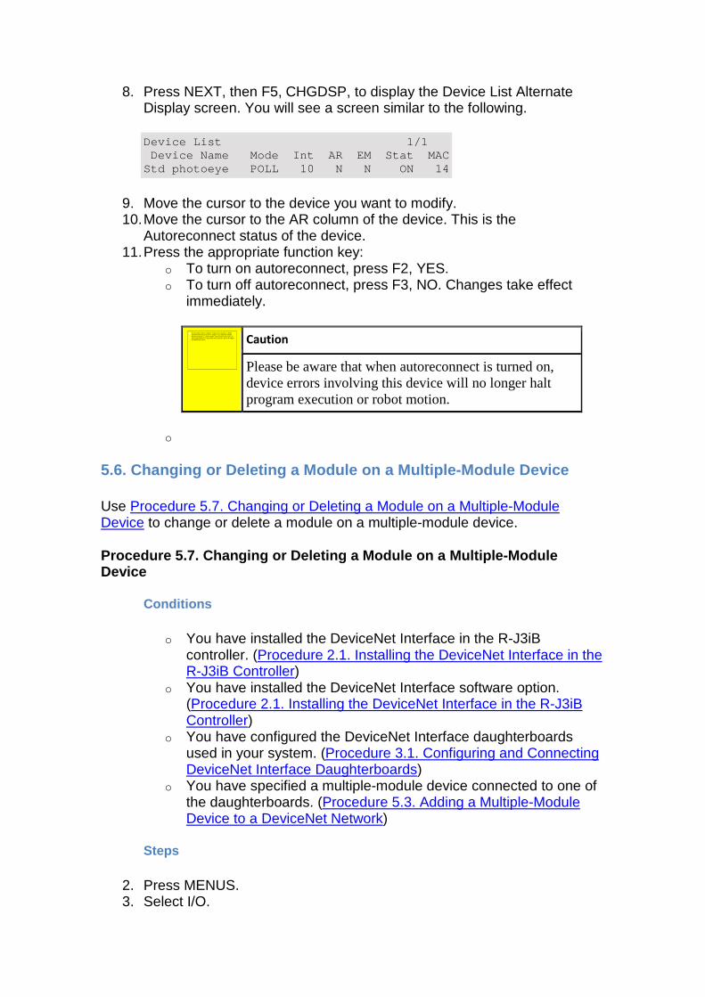
8. Press NEXT, then F5, CHGDSP, to display the Device List Alternate Display screen. You will see a screen similar to the following.
Device List 1/1 Device Name Mode Int AR EM Stat MAC Std photoeye POLL 10 N N ON 14
9. Move the cursor to the device you want to modify. 10. Move the cursor to the AR column of the device. This is the
Autoreconnect status of the device. 11. Press the appropriate function key:
o To turn on autoreconnect, press F2, YES. o To turn off autoreconnect, press F3, NO. Changes take effect
immediately.
Caution
Please be aware that when autoreconnect is turned on, device errors involving this device will no longer halt program execution or robot motion.
o
5.6. Changing or Deleting a Module on a Multiple-Mo dule Device
Use Procedure 5.7. Changing or Deleting a Module on a Multiple-Module Device to change or delete a module on a multiple-module device.
Procedure 5.7. Changing or Deleting a Module on a M ultiple-Module Device
Conditions
o You have installed the DeviceNet Interface in the R-J3iB controller. (Procedure 2.1. Installing the DeviceNet Interface in the R-J3iB Controller)
o You have installed the DeviceNet Interface software option. (Procedure 2.1. Installing the DeviceNet Interface in the R-J3iB Controller)
o You have configured the DeviceNet Interface daughterboards used in your system. (Procedure 3.1. Configuring and Connecting DeviceNet Interface Daughterboards)
o You have specified a multiple-module device connected to one of the daughterboards. (Procedure 5.3. Adding a Multiple-Module Device to a DeviceNet Network)
Steps
2. Press MENUS. 3. Select I/O.
No se puede mostrar la imagen. Puede que su equipo no tenga suficiente memoria para abrir la imagen o que ésta esté dañada. Reinicie el equipo y, a continuación, abra el archivo de nuevo. Si sigue apareciendo la x roja, puede que tenga que borrar la imagen e insertarla de nuevo.
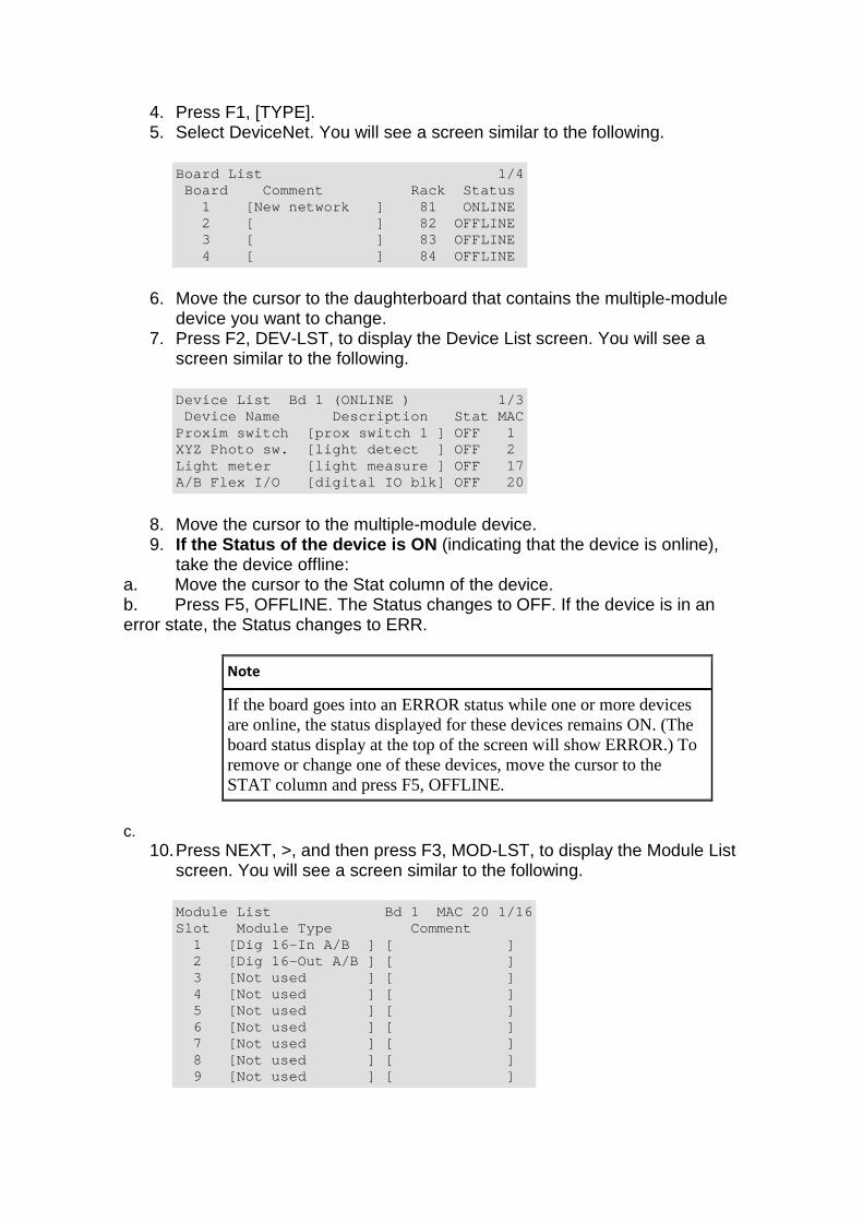
4. Press F1, [TYPE]. 5. Select DeviceNet. You will see a screen similar to the following.
Board List 1/4 Board Comment Rack Status 1 [New network ] 81 ONLINE 2 [ ] 82 OFFLINE 3 [ ] 83 OFFLINE 4 [ ] 84 OFFLINE
6. Move the cursor to the daughterboard that contains the multiple-module device you want to change.
7. Press F2, DEV-LST, to display the Device List screen. You will see a screen similar to the following.
Device List Bd 1 (ONLINE ) 1/3 Device Name Description Stat MAC Proxim switch [prox switch 1 ] OFF 1 XYZ Photo sw. [light detect ] OFF 2 Light meter [light measure ] OFF 17 A/B Flex I/O [digital IO blk] OFF 20
8. Move the cursor to the multiple-module device. 9. If the Status of the device is ON (indicating that the device is online),
take the device offline: a. Move the cursor to the Stat column of the device. b. Press F5, OFFLINE. The Status changes to OFF. If the device is in an error state, the Status changes to ERR.
Note
If the board goes into an ERROR status while one or more devices are online, the status displayed for these devices remains ON. (The board status display at the top of the screen will show ERROR.) To remove or change one of these devices, move the cursor to the STAT column and press F5, OFFLINE.
c. 10. Press NEXT, >, and then press F3, MOD-LST, to display the Module List
screen. You will see a screen similar to the following.
Module List Bd 1 MAC 20 1/16 Slot Module Type Comment 1 [Dig 16-In A/B ] [ ] 2 [Dig 16-Out A/B ] [ ] 3 [Not used ] [ ] 4 [Not used ] [ ] 5 [Not used ] [ ] 6 [Not used ] [ ] 7 [Not used ] [ ] 8 [Not used ] [ ] 9 [Not used ] [ ]
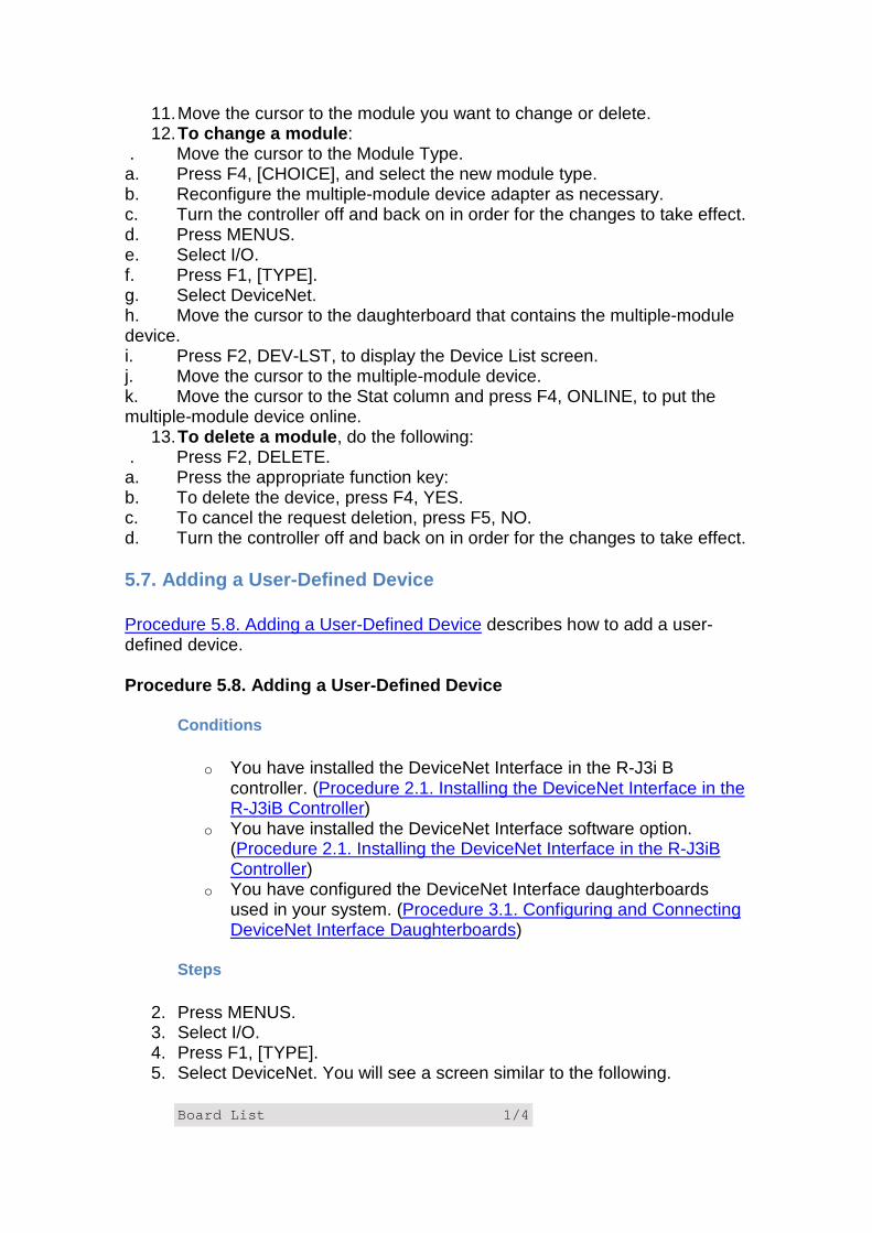
11. Move the cursor to the module you want to change or delete. 12. To change a module :
. Move the cursor to the Module Type. a. Press F4, [CHOICE], and select the new module type. b. Reconfigure the multiple-module device adapter as necessary. c. Turn the controller off and back on in order for the changes to take effect. d. Press MENUS. e. Select I/O. f. Press F1, [TYPE]. g. Select DeviceNet. h. Move the cursor to the daughterboard that contains the multiple-module device. i. Press F2, DEV-LST, to display the Device List screen. j. Move the cursor to the multiple-module device. k. Move the cursor to the Stat column and press F4, ONLINE, to put the multiple-module device online.
13. To delete a module , do the following: . Press F2, DELETE. a. Press the appropriate function key: b. To delete the device, press F4, YES. c. To cancel the request deletion, press F5, NO. d. Turn the controller off and back on in order for the changes to take effect.
5.7. Adding a User-Defined Device
Procedure 5.8. Adding a User-Defined Device describes how to add a user-defined device.
Procedure 5.8. Adding a User-Defined Device
Conditions
o You have installed the DeviceNet Interface in the R-J3i B controller. (Procedure 2.1. Installing the DeviceNet Interface in the R-J3iB Controller)
o You have installed the DeviceNet Interface software option. (Procedure 2.1. Installing the DeviceNet Interface in the R-J3iB Controller)
o You have configured the DeviceNet Interface daughterboards used in your system. (Procedure 3.1. Configuring and Connecting DeviceNet Interface Daughterboards)
Steps
2. Press MENUS. 3. Select I/O. 4. Press F1, [TYPE]. 5. Select DeviceNet. You will see a screen similar to the following.
Board List 1/4
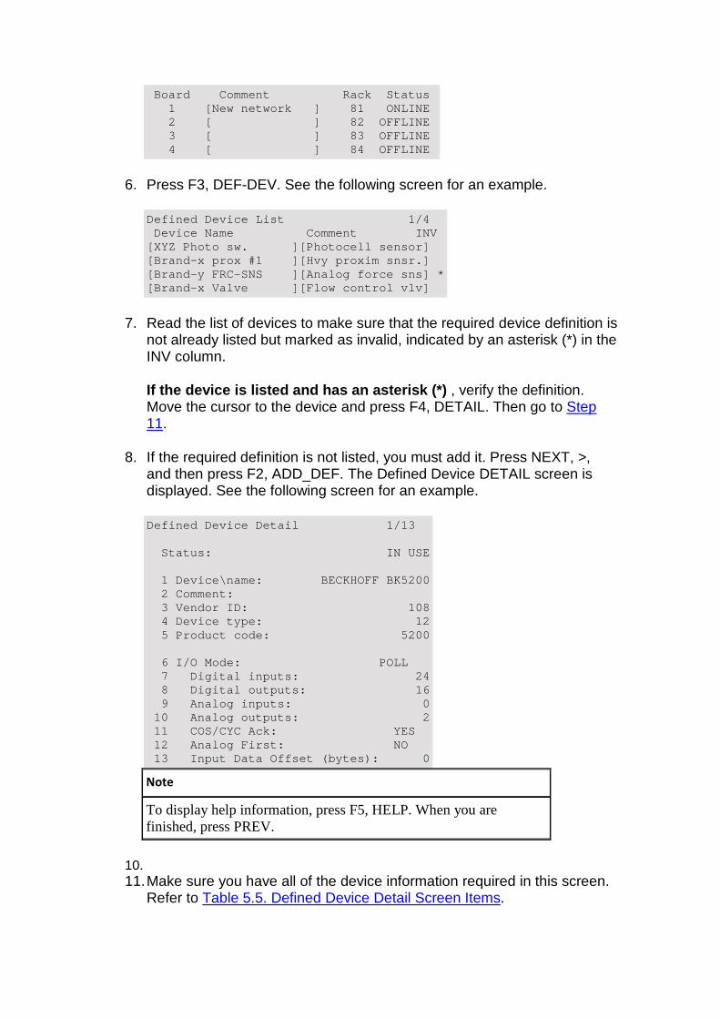
Board Comment Rack Status 1 [New network ] 81 ONLINE 2 [ ] 82 OFFLINE 3 [ ] 83 OFFLINE 4 [ ] 84 OFFLINE
6. Press F3, DEF-DEV. See the following screen for an example.
Defined Device List 1/4 Device Name Comment INV [XYZ Photo sw. ][Photocell sensor] [Brand-x prox #1 ][Hvy proxim snsr.] [Brand-y FRC-SNS ][Analog force sns] * [Brand-x Valve ][Flow control vlv]
7. Read the list of devices to make sure that the required device definition is not already listed but marked as invalid, indicated by an asterisk (*) in the INV column.
If the device is listed and has an asterisk (*) , verify the definition. Move the cursor to the device and press F4, DETAIL. Then go to Step 11.
8. If the required definition is not listed, you must add it. Press NEXT, >, and then press F2, ADD_DEF. The Defined Device DETAIL screen is displayed. See the following screen for an example.
Defined Device Detail 1/13 Status: IN USE 1 Device\name: BECKHOFF BK5200 2 Comment: 3 Vendor ID: 108 4 Device type: 12 5 Product code: 5200 6 I/O Mode: POLL 7 Digital inputs: 24 8 Digital outputs: 16 9 Analog inputs: 0 10 Analog outputs: 2 11 COS/CYC Ack: YES 12 Analog First: NO 13 Input Data Offset (bytes): 0
Note
To display help information, press F5, HELP. When you are finished, press PREV.
10. 11. Make sure you have all of the device information required in this screen.
Refer to Table 5.5. Defined Device Detail Screen Items.
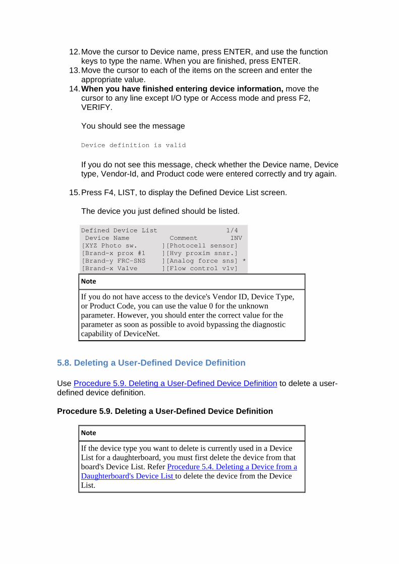
12. Move the cursor to Device name, press ENTER, and use the function keys to type the name. When you are finished, press ENTER.
13. Move the cursor to each of the items on the screen and enter the appropriate value.
14. When you have finished entering device information, move the cursor to any line except I/O type or Access mode and press F2, VERIFY.
You should see the message
Device definition is valid
If you do not see this message, check whether the Device name, Device type, Vendor-Id, and Product code were entered correctly and try again.
15. Press F4, LIST, to display the Defined Device List screen.
The device you just defined should be listed.
Defined Device List 1/4 Device Name Comment INV [XYZ Photo sw. ][Photocell sensor] [Brand-x prox #1 ][Hvy proxim snsr.] [Brand-y FRC-SNS ][Analog force sns] * [Brand-x Valve ][Flow control vlv]
Note
If you do not have access to the device's Vendor ID, Device Type, or Product Code, you can use the value 0 for the unknown parameter. However, you should enter the correct value for the parameter as soon as possible to avoid bypassing the diagnostic capability of DeviceNet.
5.8. Deleting a User-Defined Device Definition
Use Procedure 5.9. Deleting a User-Defined Device Definition to delete a user-defined device definition.
Procedure 5.9. Deleting a User-Defined Device Defin ition
Note
If the device type you want to delete is currently used in a Device List for a daughterboard, you must first delete the device from that board's Device List. Refer Procedure 5.4. Deleting a Device from a Daughterboard's Device List to delete the device from the Device List.
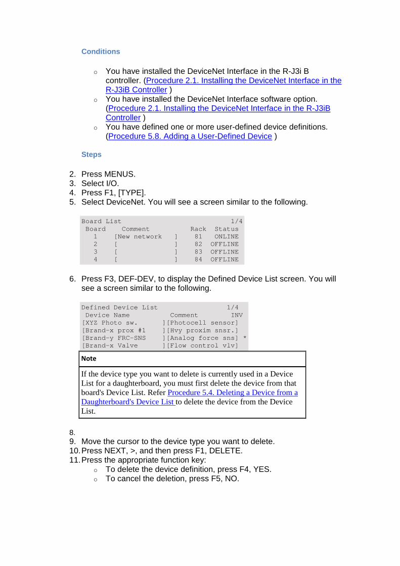
Conditions
o You have installed the DeviceNet Interface in the R-J3i B controller. (Procedure 2.1. Installing the DeviceNet Interface in the R-J3iB Controller )
o You have installed the DeviceNet Interface software option. (Procedure 2.1. Installing the DeviceNet Interface in the R-J3iB Controller )
o You have defined one or more user-defined device definitions. (Procedure 5.8. Adding a User-Defined Device )
Steps
2. Press MENUS. 3. Select I/O. 4. Press F1, [TYPE]. 5. Select DeviceNet. You will see a screen similar to the following.
Board List 1/4 Board Comment Rack Status 1 [New network ] 81 ONLINE 2 [ ] 82 OFFLINE 3 [ ] 83 OFFLINE 4 [ ] 84 OFFLINE
6. Press F3, DEF-DEV, to display the Defined Device List screen. You will see a screen similar to the following.
Defined Device List 1/4 Device Name Comment INV [XYZ Photo sw. ][Photocell sensor] [Brand-x prox #1 ][Hvy proxim snsr.] [Brand-y FRC-SNS ][Analog force sns] * [Brand-x Valve ][Flow control vlv]
Note
If the device type you want to delete is currently used in a Device List for a daughterboard, you must first delete the device from that board's Device List. Refer Procedure 5.4. Deleting a Device from a Daughterboard's Device List to delete the device from the Device List.
8. 9. Move the cursor to the device type you want to delete. 10. Press NEXT, >, and then press F1, DELETE. 11. Press the appropriate function key:
o To delete the device definition, press F4, YES. o To cancel the deletion, press F5, NO.
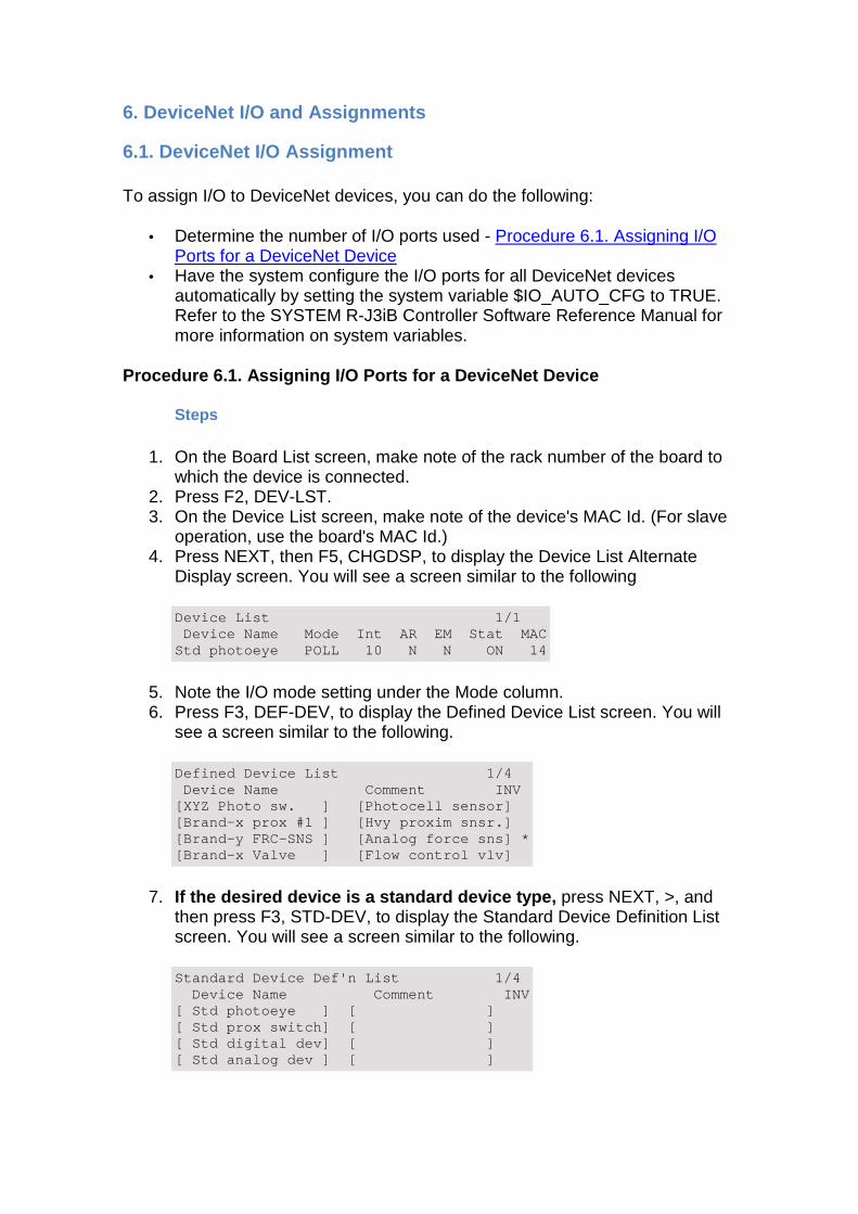
6. DeviceNet I/O and Assignments
6.1. DeviceNet I/O Assignment
To assign I/O to DeviceNet devices, you can do the following:
• Determine the number of I/O ports used - Procedure 6.1. Assigning I/O Ports for a DeviceNet Device
• Have the system configure the I/O ports for all DeviceNet devices automatically by setting the system variable $IO_AUTO_CFG to TRUE. Refer to the SYSTEM R-J3iB Controller Software Reference Manual for more information on system variables.
Procedure 6.1. Assigning I/O Ports for a DeviceNet Device
Steps
1. On the Board List screen, make note of the rack number of the board to which the device is connected.
2. Press F2, DEV-LST. 3. On the Device List screen, make note of the device's MAC Id. (For slave
operation, use the board's MAC Id.) 4. Press NEXT, then F5, CHGDSP, to display the Device List Alternate
Display screen. You will see a screen similar to the following
Device List 1/1 Device Name Mode Int AR EM Stat MAC Std photoeye POLL 10 N N ON 14
5. Note the I/O mode setting under the Mode column. 6. Press F3, DEF-DEV, to display the Defined Device List screen. You will
see a screen similar to the following.
Defined Device List 1/4 Device Name Comment INV [XYZ Photo sw. ] [Photocell sensor] [Brand-x prox #1 ] [Hvy proxim snsr.] [Brand-y FRC-SNS ] [Analog force sns] * [Brand-x Valve ] [Flow control vlv]
7. If the desired device is a standard device type, press NEXT, >, and then press F3, STD-DEV, to display the Standard Device Definition List screen. You will see a screen similar to the following.
Standard Device Def'n List 1/4 Device Name Comment INV [ Std photoeye ] [ ] [ Std prox switch] [ ] [ Std digital dev] [ ] [ Std analog dev ] [ ]
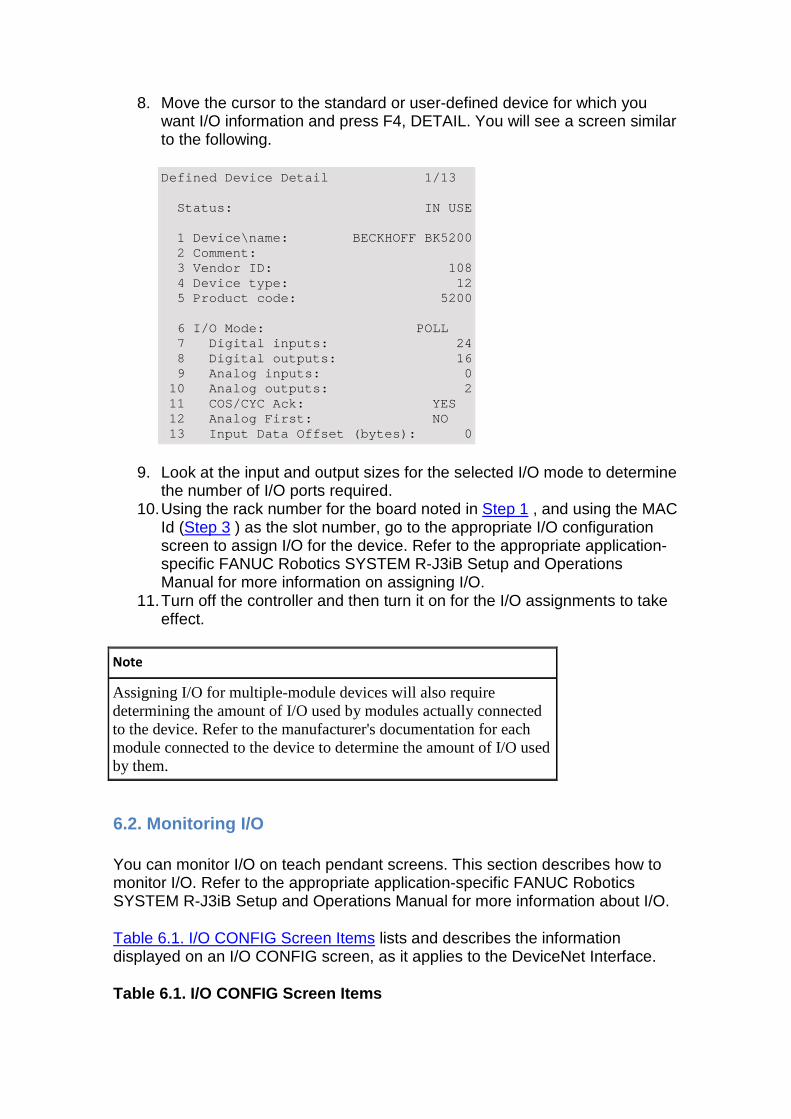
8. Move the cursor to the standard or user-defined device for which you want I/O information and press F4, DETAIL. You will see a screen similar to the following.
Defined Device Detail 1/13 Status: IN USE 1 Device\name: BECKHOFF BK5200 2 Comment: 3 Vendor ID: 108 4 Device type: 12 5 Product code: 5200 6 I/O Mode: POLL 7 Digital inputs: 24 8 Digital outputs: 16 9 Analog inputs: 0 10 Analog outputs: 2 11 COS/CYC Ack: YES 12 Analog First: NO 13 Input Data Offset (bytes): 0
9. Look at the input and output sizes for the selected I/O mode to determine the number of I/O ports required.
10. Using the rack number for the board noted in Step 1 , and using the MAC Id (Step 3 ) as the slot number, go to the appropriate I/O configuration screen to assign I/O for the device. Refer to the appropriate application-specific FANUC Robotics SYSTEM R-J3iB Setup and Operations Manual for more information on assigning I/O.
11. Turn off the controller and then turn it on for the I/O assignments to take effect.
Note
Assigning I/O for multiple-module devices will also require determining the amount of I/O used by modules actually connected to the device. Refer to the manufacturer's documentation for each module connected to the device to determine the amount of I/O used by them.
6.2. Monitoring I/O
You can monitor I/O on teach pendant screens. This section describes how to monitor I/O. Refer to the appropriate application-specific FANUC Robotics SYSTEM R-J3iB Setup and Operations Manual for more information about I/O.
Table 6.1. I/O CONFIG Screen Items lists and describes the information displayed on an I/O CONFIG screen, as it applies to the DeviceNet Interface.
Table 6.1. I/O CONFIG Screen Items
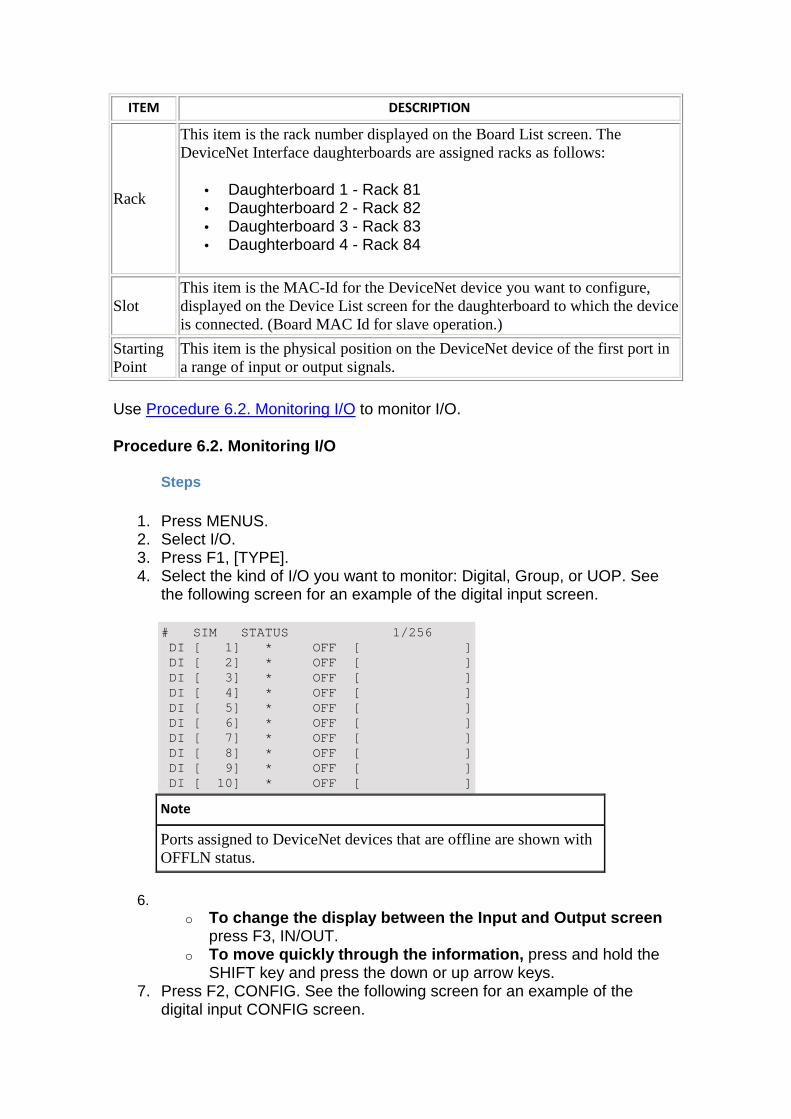
ITEM DESCRIPTION
Rack
This item is the rack number displayed on the Board List screen. The DeviceNet Interface daughterboards are assigned racks as follows:
• Daughterboard 1 - Rack 81 • Daughterboard 2 - Rack 82 • Daughterboard 3 - Rack 83 • Daughterboard 4 - Rack 84
Slot This item is the MAC-Id for the DeviceNet device you want to configure, displayed on the Device List screen for the daughterboard to which the device is connected. (Board MAC Id for slave operation.)
Starting Point
This item is the physical position on the DeviceNet device of the first port in a range of input or output signals.
Use Procedure 6.2. Monitoring I/O to monitor I/O.
Procedure 6.2. Monitoring I/O
Steps
1. Press MENUS. 2. Select I/O. 3. Press F1, [TYPE]. 4. Select the kind of I/O you want to monitor: Digital, Group, or UOP. See
the following screen for an example of the digital input screen.
# SIM STATUS 1/256 DI [ 1] * OFF [ ] DI [ 2] * OFF [ ] DI [ 3] * OFF [ ] DI [ 4] * OFF [ ] DI [ 5] * OFF [ ] DI [ 6] * OFF [ ] DI [ 7] * OFF [ ] DI [ 8] * OFF [ ] DI [ 9] * OFF [ ] DI [ 10] * OFF [ ]
Note
Ports assigned to DeviceNet devices that are offline are shown with OFFLN status.
6. o To change the display between the Input and Output screen
press F3, IN/OUT. o To move quickly through the information, press and hold the
SHIFT key and press the down or up arrow keys. 7. Press F2, CONFIG. See the following screen for an example of the
digital input CONFIG screen.
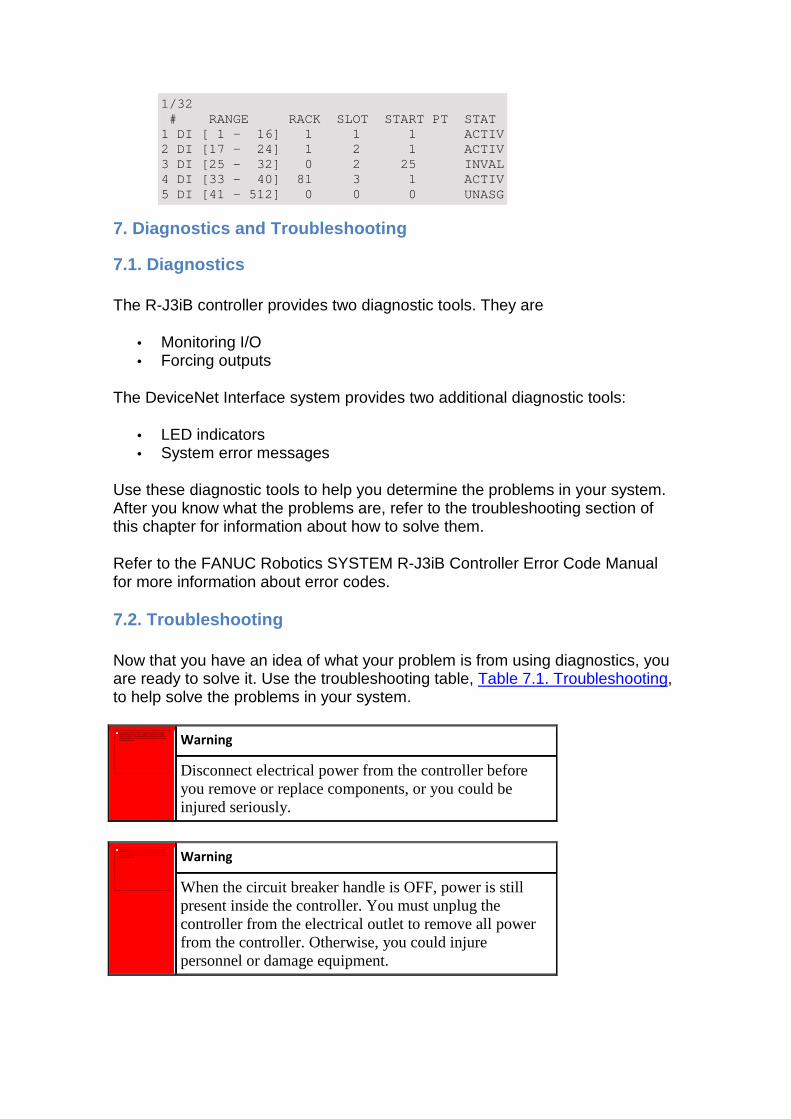
1/32 # RANGE RACK SLOT START PT STAT 1 DI [ 1 - 16] 1 1 1 ACTIV 2 DI [17 - 24] 1 2 1 ACTIV 3 DI [25 - 32] 0 2 25 INVAL 4 DI [33 - 40] 81 3 1 ACTIV 5 DI [41 - 512] 0 0 0 UNASG
7. Diagnostics and Troubleshooting
7.1. Diagnostics
The R-J3iB controller provides two diagnostic tools. They are
• Monitoring I/O • Forcing outputs
The DeviceNet Interface system provides two additional diagnostic tools:
• LED indicators • System error messages
Use these diagnostic tools to help you determine the problems in your system. After you know what the problems are, refer to the troubleshooting section of this chapter for information about how to solve them.
Refer to the FANUC Robotics SYSTEM R-J3iB Controller Error Code Manual for more information about error codes.
7.2. Troubleshooting
Now that you have an idea of what your problem is from using diagnostics, you are ready to solve it. Use the troubleshooting table, Table 7.1. Troubleshooting, to help solve the problems in your system.
Warning
Disconnect electrical power from the controller before you remove or replace components, or you could be injured seriously.
Warning
When the circuit breaker handle is OFF, power is still present inside the controller. You must unplug the controller from the electrical outlet to remove all power from the controller. Otherwise, you could injure personnel or damage equipment.
No se puede mostrar la imagen. Puede que su equipo no tenga suficiente memoria para abrir la imagen o que ésta esté dañada. Reinicie el equipo y, a continuación, abra el archivo de nuevo. Si sigue apareciendo la x roja, puede que tenga que borrar la imagen e insertarla de nuevo.
No se puede mostrar la imagen. Puede que su equipo no tenga suficiente memoria para abrir la imagen o que ésta esté dañada. Reinicie el equipo y, a continuación, abra el archivo de nuevo. Si sigue apareciendo la x roja, puede que tenga que borrar la imagen e insertarla de nuevo.
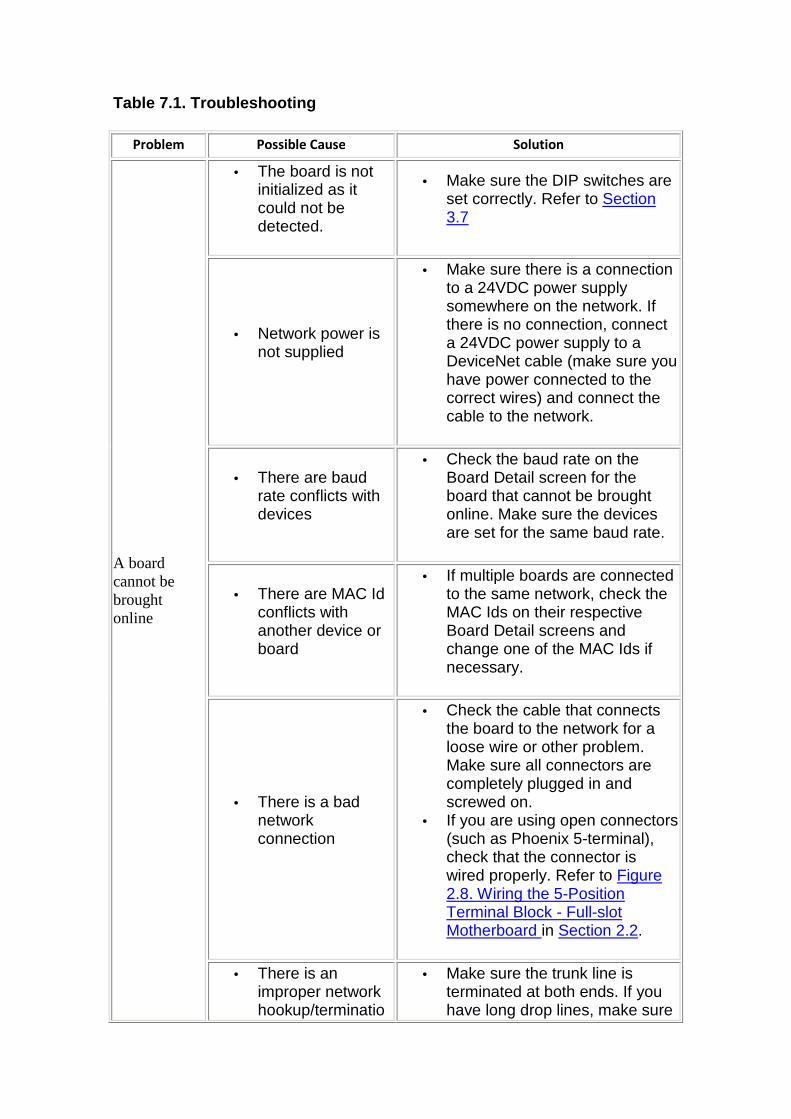
Table 7.1. Troubleshooting
Problem Possible Cause Solution
A board cannot be brought online
• The board is not initialized as it could not be detected.
• Make sure the DIP switches are set correctly. Refer to Section 3.7
• Network power is not supplied
• Make sure there is a connection to a 24VDC power supply somewhere on the network. If there is no connection, connect a 24VDC power supply to a DeviceNet cable (make sure you have power connected to the correct wires) and connect the cable to the network.
• There are baud rate conflicts with devices
• Check the baud rate on the Board Detail screen for the board that cannot be brought online. Make sure the devices are set for the same baud rate.
• There are MAC Id conflicts with another device or board
• If multiple boards are connected to the same network, check the MAC Ids on their respective Board Detail screens and change one of the MAC Ids if necessary.
• There is a bad network connection
• Check the cable that connects the board to the network for a loose wire or other problem. Make sure all connectors are completely plugged in and screwed on.
• If you are using open connectors (such as Phoenix 5-terminal), check that the connector is wired properly. Refer to Figure 2.8. Wiring the 5-Position Terminal Block - Full-slot Motherboard in Section 2.2.
• There is an improper network hookup/terminatio
• Make sure the trunk line is terminated at both ends. If you have long drop lines, make sure
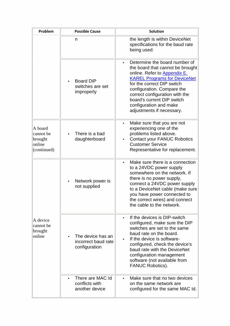
Problem Possible Cause Solution
n the length is within DeviceNet specifications for the baud rate being used.
• Board DIP switches are set improperly
• Determine the board number of the board that cannot be brought online. Refer to Appendix E. KAREL Programs for DeviceNet for the correct DIP switch configuration. Compare the correct configuration with the board's current DIP switch configuration and make adjustments if necessary.
A board cannot be brought online (continued)
• There is a bad daughterboard
• Make sure that you are not experiencing one of the problems listed above.
• Contact your FANUC Robotics Customer Service Representative for replacement.
A device cannot be brought online
• Network power is not supplied
• Make sure there is a connection to a 24VDC power supply somewhere on the network. If there is no power supply, connect a 24VDC power supply to a DeviceNet cable (make sure you have power connected to the correct wires) and connect the cable to the network.
• The device has an incorrect baud rate configuration
• If the devices is DIP-switch configured, make sure the DIP switches are set to the same baud rate on the board.
• If the device is software-configured, check the device's baud rate with the DeviceNet configuration management software (not available from FANUC Robotics).
• There are MAC Id conflicts with another device
• Make sure that no two devices on the same network are configured for the same MAC Id.
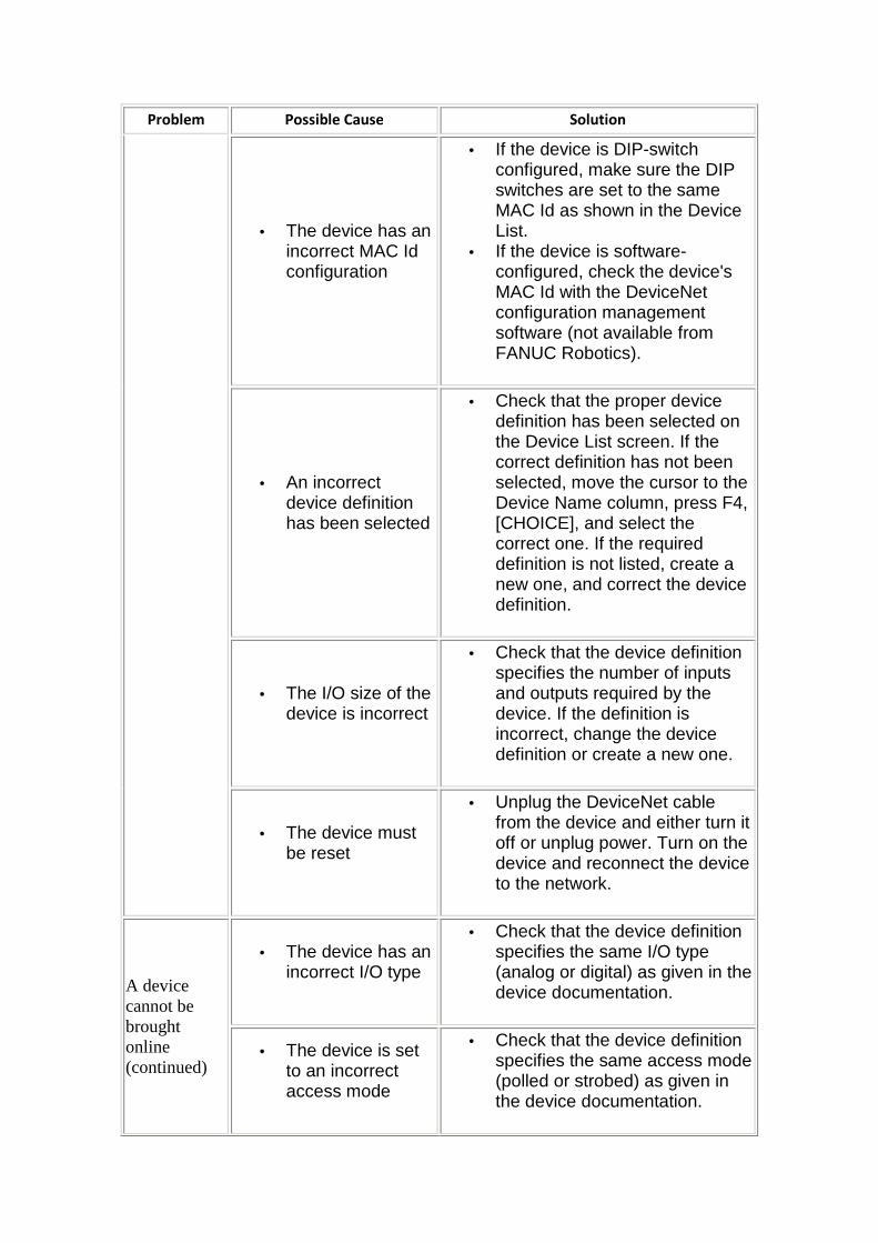
Problem Possible Cause Solution
• The device has an incorrect MAC Id configuration
• If the device is DIP-switch configured, make sure the DIP switches are set to the same MAC Id as shown in the Device List.
• If the device is software-configured, check the device's MAC Id with the DeviceNet configuration management software (not available from FANUC Robotics).
• An incorrect device definition has been selected
• Check that the proper device definition has been selected on the Device List screen. If the correct definition has not been selected, move the cursor to the Device Name column, press F4, [CHOICE], and select the correct one. If the required definition is not listed, create a new one, and correct the device definition.
• The I/O size of the device is incorrect
• Check that the device definition specifies the number of inputs and outputs required by the device. If the definition is incorrect, change the device definition or create a new one.
• The device must be reset
• Unplug the DeviceNet cable from the device and either turn it off or unplug power. Turn on the device and reconnect the device to the network.
A device cannot be brought online (continued)
• The device has an incorrect I/O type
• Check that the device definition specifies the same I/O type (analog or digital) as given in the device documentation.
• The device is set to an incorrect access mode
• Check that the device definition specifies the same access mode (polled or strobed) as given in the device documentation.
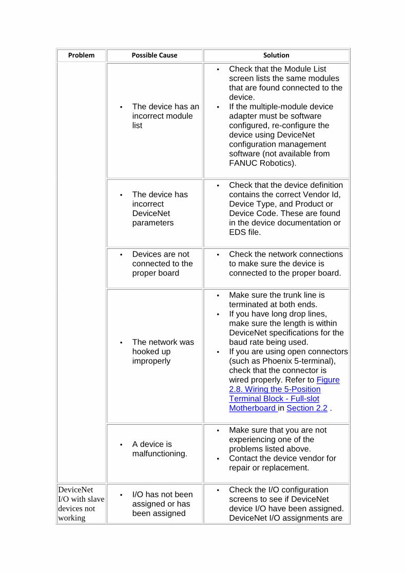
Problem Possible Cause Solution
• The device has an incorrect module list
• Check that the Module List screen lists the same modules that are found connected to the device.
• If the multiple-module device adapter must be software configured, re-configure the device using DeviceNet configuration management software (not available from FANUC Robotics).
• The device has incorrect DeviceNet parameters
• Check that the device definition contains the correct Vendor Id, Device Type, and Product or Device Code. These are found in the device documentation or EDS file.
• Devices are not connected to the proper board
• Check the network connections to make sure the device is connected to the proper board.
• The network was hooked up improperly
• Make sure the trunk line is terminated at both ends.
• If you have long drop lines, make sure the length is within DeviceNet specifications for the baud rate being used.
• If you are using open connectors (such as Phoenix 5-terminal), check that the connector is wired properly. Refer to Figure 2.8. Wiring the 5-Position Terminal Block - Full-slot Motherboard in Section 2.2 .
• A device is malfunctioning.
• Make sure that you are not experiencing one of the problems listed above.
• Contact the device vendor for repair or replacement.
DeviceNet I/O with slave devices not working
• I/O has not been assigned or has been assigned
• Check the I/O configuration screens to see if DeviceNet device I/O have been assigned. DeviceNet I/O assignments are
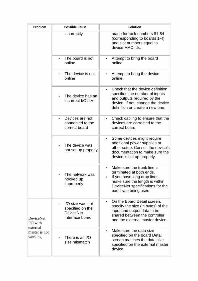
Problem Possible Cause Solution
incorrectly made for rack numbers 81-84 (corresponding to boards 1-4) and slot numbers equal to device MAC Ids.
• The board is not online
• Attempt to bring the board online.
• The device is not online
• Attempt to bring the device online.
• The device has an incorrect I/O size
• Check that the device definition specifies the number of inputs and outputs required by the device. If not, change the device definition or create a new one.
• Devices are not connected to the correct board
• Check cabling to ensure that the devices are corrected to the correct board.
• The device was not set up properly
• Some devices might require additional power supplies or other setup. Consult the device's documentation to make sure the device is set up properly.
• The network was hooked up improperly
• Make sure the trunk line is terminated at both ends.
• If you have long drop lines, make sure the length is within DeviceNet specifications for the baud rate being used.
DeviceNet I/O with external master is not working
• I/O size was not specified on the DeviceNet Interface board
• On the Board Detail screen, specify the size (in bytes) of the input and output data to be shared between the controller and the external master device.
• There is an I/O size mismatch
• Make sure the data size specified on the board Detail screen matches the data size specified on the external master device.
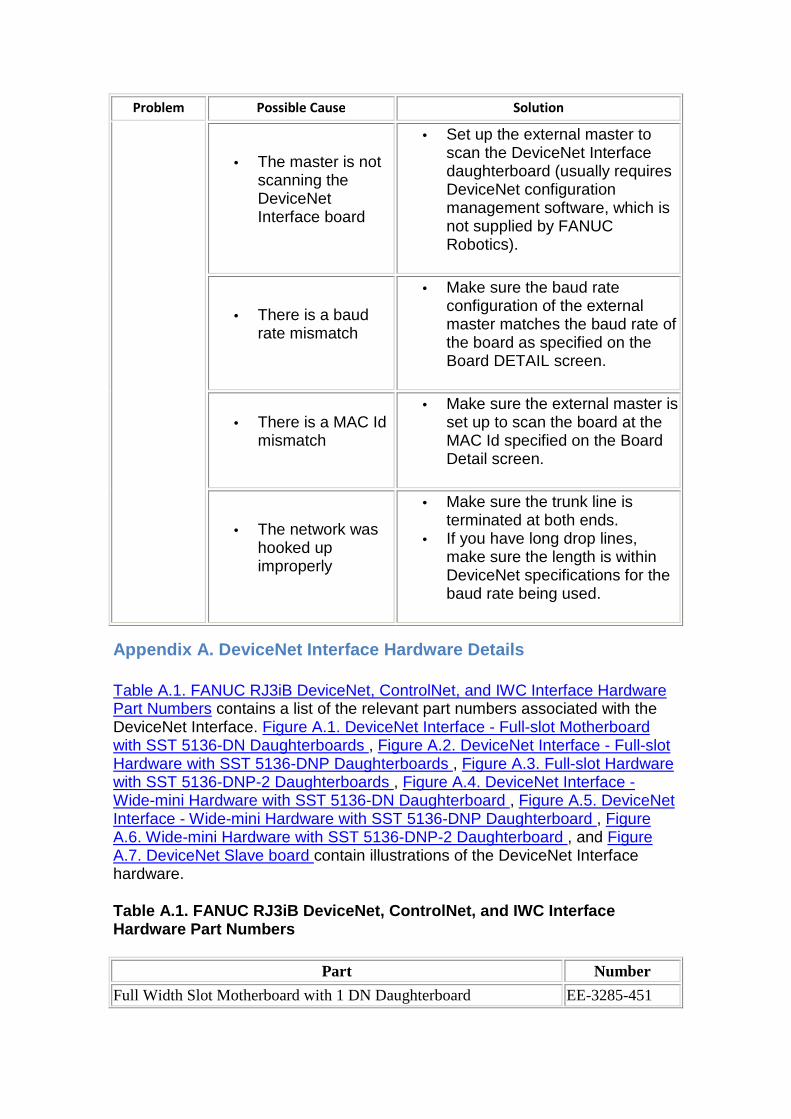
Problem Possible Cause Solution
• The master is not scanning the DeviceNet Interface board
• Set up the external master to scan the DeviceNet Interface daughterboard (usually requires DeviceNet configuration management software, which is not supplied by FANUC Robotics).
• There is a baud rate mismatch
• Make sure the baud rate configuration of the external master matches the baud rate of the board as specified on the Board DETAIL screen.
• There is a MAC Id mismatch
• Make sure the external master is set up to scan the board at the MAC Id specified on the Board Detail screen.
• The network was hooked up improperly
• Make sure the trunk line is terminated at both ends.
• If you have long drop lines, make sure the length is within DeviceNet specifications for the baud rate being used.
Appendix A. DeviceNet Interface Hardware Details
Table A.1. FANUC RJ3iB DeviceNet, ControlNet, and IWC Interface Hardware Part Numbers contains a list of the relevant part numbers associated with the DeviceNet Interface. Figure A.1. DeviceNet Interface - Full-slot Motherboard with SST 5136-DN Daughterboards , Figure A.2. DeviceNet Interface - Full-slot Hardware with SST 5136-DNP Daughterboards , Figure A.3. Full-slot Hardware with SST 5136-DNP-2 Daughterboards , Figure A.4. DeviceNet Interface - Wide-mini Hardware with SST 5136-DN Daughterboard , Figure A.5. DeviceNet Interface - Wide-mini Hardware with SST 5136-DNP Daughterboard , Figure A.6. Wide-mini Hardware with SST 5136-DNP-2 Daughterboard , and Figure A.7. DeviceNet Slave board contain illustrations of the DeviceNet Interface hardware.
Table A.1. FANUC RJ3iB DeviceNet, ControlNet, and I WC Interface Hardware Part Numbers
Part Number
Full Width Slot Motherboard with 1 DN Daughterboard EE-3285-451
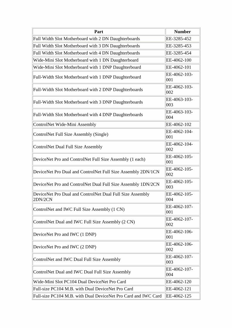
Part Number
Full Width Slot Motherboard with 2 DN Daughterboards EE-3285-452
Full Width Slot Motherboard with 3 DN Daughterboards EE-3285-453
Full Width Slot Motherboard with 4 DN Daughterboards EE-3285-454
Wide-Mini Slot Motherboard with 1 DN Daughterboard EE-4062-100
Wide-Mini Slot Motherboard with 1 DNP Daughterboard EE-4062-101
Full-Width Slot Motherboard with 1 DNP Daughterboard EE-4062-103-001
Full-Width Slot Motherboard with 2 DNP Daughterboards EE-4062-103-002
Full-Width Slot Motherboard with 3 DNP Daughterboards EE-4063-103-003
Full-Width Slot Motherboard with 4 DNP Daughterboards EE-4063-103-004
ControlNet Wide-Mini Assembly EE-4062-102
ControlNet Full Size Assembly (Single) EE-4062-104-001
ControlNet Dual Full Size Assembly EE-4062-104-002
DeviceNet Pro and ControlNet Full Size Assembly (1 each) EE-4062-105-001
DeviceNet Pro Dual and ControlNet Full Size Assembly 2DN/1CN EE-4062-105-002
DeviceNet Pro and ControlNet Dual Full Size Assembly 1DN/2CN EE-4062-105-003
DeviceNet Pro Dual and ControlNet Dual Full Size Assembly 2DN/2CN
EE-4062-105-004
ControlNet and IWC Full Size Assembly (1 CN) EE-4062-107-001
ControlNet Dual and IWC Full Size Assembly (2 CN) EE-4062-107-002
DeviceNet Pro and IWC (1 DNP) EE-4062-106-001
DeviceNet Pro and IWC (2 DNP) EE-4062-106-002
ControlNet and IWC Dual Full Size Assembly EE-4062-107-003
ControlNet Dual and IWC Dual Full Size Assembly EE-4062-107-004
Wide-Mini Slot PC104 Dual DeviceNet Pro Card EE-4062-120
Full-size PC104 M.B. with Dual DeviceNet Pro Card EE-4062-121
Full-size PC104 M.B. with Dual DeviceNet Pro Card and IWC Card EE-4062-125
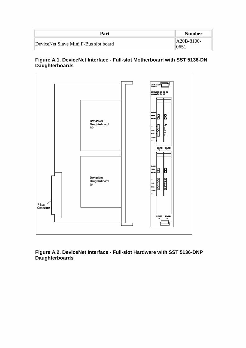
Part Number
DeviceNet Slave Mini F-Bus slot board A20B-8100-0651
Figure A.1. DeviceNet Interface - Full-slot Motherb oard with SST 5136-DN Daughterboards
Figure A.2. DeviceNet Interface - Full-slot Hardwar e with SST 5136-DNP Daughterboards
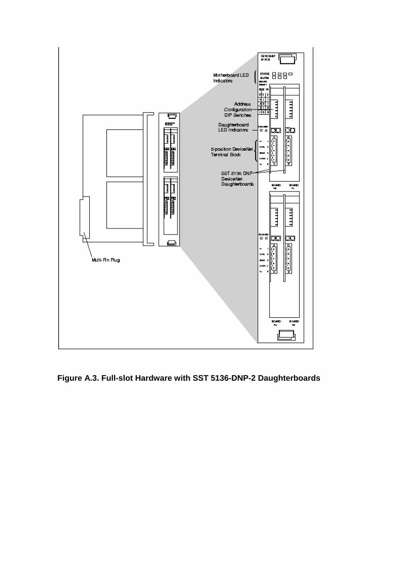
Figure A.3. Full-slot Hardware with SST 5136-DNP-2 Daughterboards

Figure A.4. DeviceNet Interface - Wide-mini Hardwar e with SST 5136-DN Daughterboard
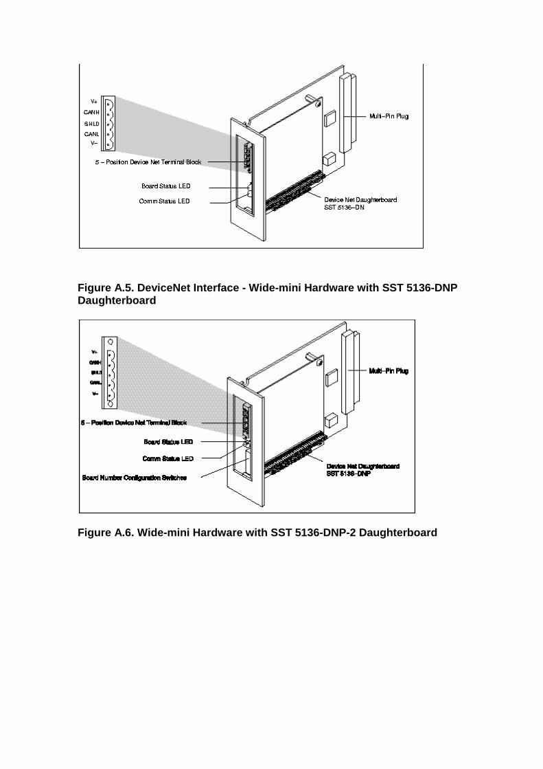
Figure A.5. DeviceNet Interface - Wide-mini Hardwar e with SST 5136-DNP Daughterboard
Figure A.6. Wide-mini Hardware with SST 5136-DNP-2 Daughterboard
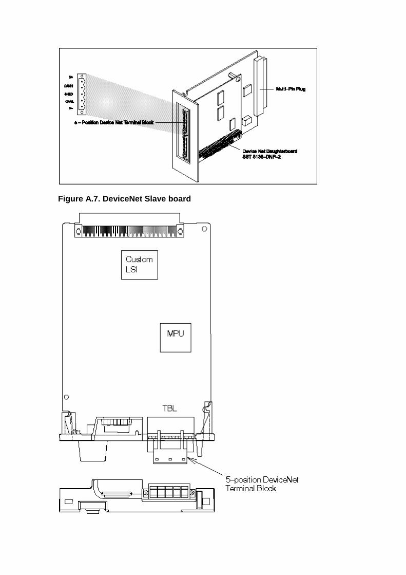
Figure A.7. DeviceNet Slave board
Appendix B. Response Time
The response time of the system is the amount of time it takes an I/O signal to propagate through the system to its destination. The response time of a DeviceNet network depends most significantly on three factors:
• The number of devices on the network • The amount of data being transmitted across the network • The communications or baud rate
Response Time Calculation
To calculate the response time, the following information must be taken into account (all expressed in milliseconds):
• Transmission time per bit (Tb) - the time required to transmit a bit across the network.
Tb = 1 / baud rate (baud rate = 125, 250, or 500 Kbaud) = 0.008 ms for 125 Kbaud= 0.004 ms for 250 Kbaud= 0.002 ms for 500 Kbaud
• Transmission time per byte (TB) - the time required to transmit a byte (8 bits) across the network.
TB = 8 x Tb
• Inter-message interval (Ti) - the time required between DeviceNet messages.
Ti = 0.250 ms
• CAN message interval (Tc) - CAN (Controller Area Network) based messages such as those transmitted on DeviceNet networks contain 44 bits of status and identification information.
Tc = 44 *Tb
• Scanner refresh and memory access interval (Tsc)
Tsc = 1.5 ms
• The number of strobed devices (Ns) • The number of polled devices (Np) • The number of input bytes from strobed devices (Bs) • The total number of input and output bytes for poll ed devices (Bp)
The response time is calculated as shown in Figure B.1. Response Time .
Figure B.1. Response Time
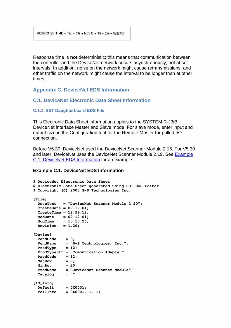
Response time is not deterministic; this means that communication between the controller and the DeviceNet network occurs asynchronously, not at set intervals. In addition, noise on the network might cause retransmissions, and other traffic on the network might cause the interval to be longer than at other times.
Appendix C. DeviceNet EDS Information
C.1. DeviceNet Electronic Data Sheet Information
C.1.1. SST Daughterboard EDS File
This Electronic Data Sheet information applies to the SYSTEM R-J3iB DeviceNet interface Master and Slave mode. For slave mode, enter input and output size in the Configuration tool for the Remote Master for polled I/O connection.
Before V5.30, DeviceNet used the DeviceNet Scanner Module 2.16. For V5.30 and later, DeviceNet uses the DeviceNet Scanner Module 2.19. See Example C.1. DeviceNet EDS Information for an example.
Example C.1. DeviceNet EDS Information
$ DeviceNet Electronic Data Sheet $ Electronic Data Sheet generated using SST EDS Editor $ Copyright (C) 2000 S-S Technologies Inc. [File] DescText = "DeviceNet Scanner Module 2.20"; CreateDate = 02-12-01; CreateTime = 12:59:12; ModDate = 02-12-01; ModTime = 15:13:26; Revision = 1.20; [Device] VendCode = 8; VendName = "S-S Technologies, Inc."; ProdType = 12; ProdTypeStr = "Communication Adapter"; ProdCode = 12; MajRev = 2; MinRev = 20; ProdName = "DeviceNet Scanner Module"; Catalog = ""; [IO_Info] Default = 0X0001; PollInfo = 0X0001, 1, 1;
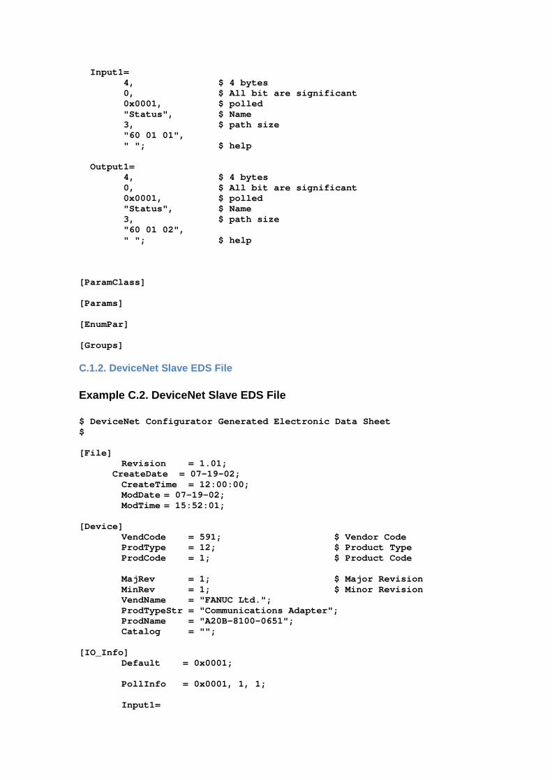
Input1= 4, $ 4 bytes 0, $ All bit are significant 0x0001, $ polled "Status", $ Name 3, $ path size "60 01 01", " "; $ help Output1= 4, $ 4 bytes 0, $ All bit are significant 0x0001, $ polled "Status", $ Name 3, $ path size "60 01 02", " "; $ help [ParamClass] [Params] [EnumPar] [Groups]
C.1.2. DeviceNet Slave EDS File
Example C.2. DeviceNet Slave EDS File
$ DeviceNet Configurator Generated Electronic Data Sheet $ [File] Revision = 1.01; CreateDate = 07-19-02; CreateTime = 12:00:00; ModDate = 07-19-02; ModTime = 15:52:01; [Device] VendCode = 591; $ Vendor Code ProdType = 12; $ Product Type ProdCode = 1; $ Product Code MajRev = 1; $ Major Revision MinRev = 1; $ Minor Revision VendName = "FANUC Ltd."; ProdTypeStr = "Communications Adapter"; ProdName = "A20B-8100-0651"; Catalog = ""; [IO_Info] Default = 0x0001; PollInfo = 0x0001, 1, 1; Input1=
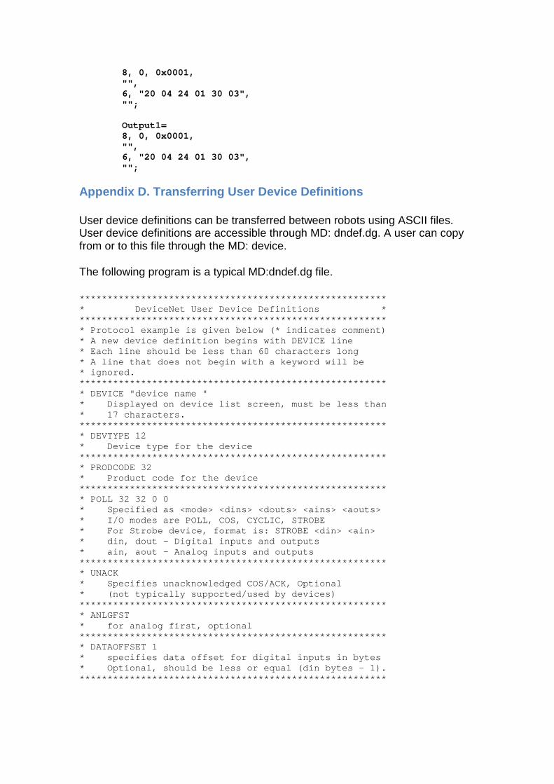
8, 0, 0x0001, "", 6, "20 04 24 01 30 03", ""; Output1= 8, 0, 0x0001, "", 6, "20 04 24 01 30 03", "";
Appendix D. Transferring User Device Definitions
User device definitions can be transferred between robots using ASCII files. User device definitions are accessible through MD: dndef.dg. A user can copy from or to this file through the MD: device.
The following program is a typical MD:dndef.dg file.
*************************************************** **** * DeviceNet User Device Definitions * *************************************************** **** * Protocol example is given below (* indicates comm ent) * A new device definition begins with DEVICE line * Each line should be less than 60 characters long * A line that does not begin with a keyword will be * ignored. *************************************************** **** * DEVICE "device name " * Displayed on device list screen, must be less than * 17 characters. *************************************************** **** * DEVTYPE 12 * Device type for the device *************************************************** **** * PRODCODE 32 * Product code for the device *************************************************** **** * POLL 32 32 0 0 * Specified as <mode> <dins> <douts> <ains> <aou ts> * I/O modes are POLL, COS, CYCLIC, STROBE * For Strobe device, format is: STROBE <din> <ai n> * din, dout - Digital inputs and outputs * ain, aout - Analog inputs and outputs *************************************************** **** * UNACK * Specifies unacknowledged COS/ACK, Optional * (not typically supported/used by devices) *************************************************** **** * ANLGFST * for analog first, optional *************************************************** **** * DATAOFFSET 1 * specifies data offset for digital inputs in by tes * Optional, should be less or equal (din bytes - 1). *************************************************** ****
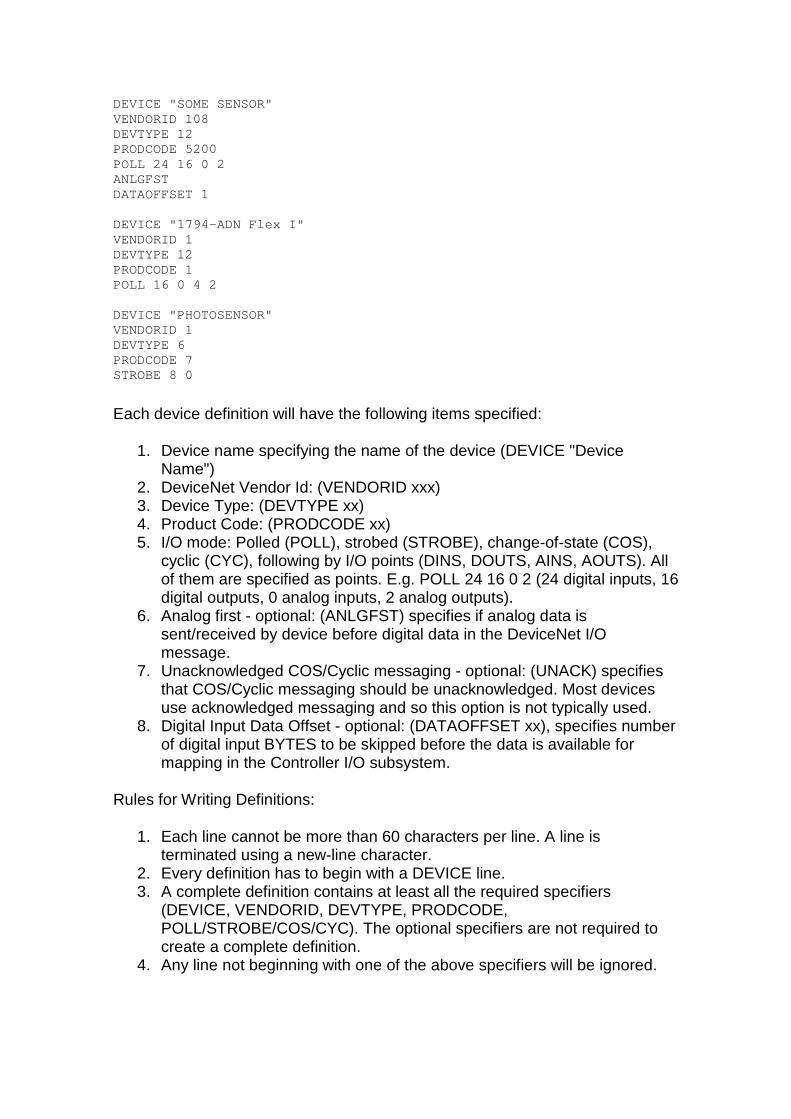
DEVICE "SOME SENSOR" VENDORID 108 DEVTYPE 12 PRODCODE 5200 POLL 24 16 0 2 ANLGFST DATAOFFSET 1 DEVICE "1794-ADN Flex I" VENDORID 1 DEVTYPE 12 PRODCODE 1 POLL 16 0 4 2 DEVICE "PHOTOSENSOR" VENDORID 1 DEVTYPE 6 PRODCODE 7 STROBE 8 0
Each device definition will have the following items specified:
1. Device name specifying the name of the device (DEVICE "Device Name")
2. DeviceNet Vendor Id: (VENDORID xxx) 3. Device Type: (DEVTYPE xx) 4. Product Code: (PRODCODE xx) 5. I/O mode: Polled (POLL), strobed (STROBE), change-of-state (COS),
cyclic (CYC), following by I/O points (DINS, DOUTS, AINS, AOUTS). All of them are specified as points. E.g. POLL 24 16 0 2 (24 digital inputs, 16 digital outputs, 0 analog inputs, 2 analog outputs).
6. Analog first - optional: (ANLGFST) specifies if analog data is sent/received by device before digital data in the DeviceNet I/O message.
7. Unacknowledged COS/Cyclic messaging - optional: (UNACK) specifies that COS/Cyclic messaging should be unacknowledged. Most devices use acknowledged messaging and so this option is not typically used.
8. Digital Input Data Offset - optional: (DATAOFFSET xx), specifies number of digital input BYTES to be skipped before the data is available for mapping in the Controller I/O subsystem.
Rules for Writing Definitions:
1. Each line cannot be more than 60 characters per line. A line is terminated using a new-line character.
2. Every definition has to begin with a DEVICE line. 3. A complete definition contains at least all the required specifiers
(DEVICE, VENDORID, DEVTYPE, PRODCODE, POLL/STROBE/COS/CYC). The optional specifiers are not required to create a complete definition.
4. Any line not beginning with one of the above specifiers will be ignored.
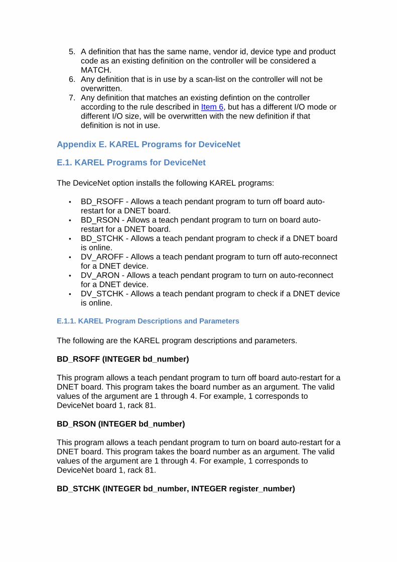
5. A definition that has the same name, vendor id, device type and product code as an existing definition on the controller will be considered a MATCH.
6. Any definition that is in use by a scan-list on the controller will not be overwritten.
7. Any definition that matches an existing defintion on the controller according to the rule described in Item 6, but has a different I/O mode or different I/O size, will be overwritten with the new definition if that definition is not in use.
Appendix E. KAREL Programs for DeviceNet
E.1. KAREL Programs for DeviceNet
The DeviceNet option installs the following KAREL programs:
• BD_RSOFF - Allows a teach pendant program to turn off board auto-restart for a DNET board.
• BD_RSON - Allows a teach pendant program to turn on board auto-restart for a DNET board.
• BD_STCHK - Allows a teach pendant program to check if a DNET board is online.
• DV_AROFF - Allows a teach pendant program to turn off auto-reconnect for a DNET device.
• DV_ARON - Allows a teach pendant program to turn on auto-reconnect for a DNET device.
• DV_STCHK - Allows a teach pendant program to check if a DNET device is online.
E.1.1. KAREL Program Descriptions and Parameters
The following are the KAREL program descriptions and parameters.
BD_RSOFF (INTEGER bd_number)
This program allows a teach pendant program to turn off board auto-restart for a DNET board. This program takes the board number as an argument. The valid values of the argument are 1 through 4. For example, 1 corresponds to DeviceNet board 1, rack 81.
BD_RSON (INTEGER bd_number)
This program allows a teach pendant program to turn on board auto-restart for a DNET board. This program takes the board number as an argument. The valid values of the argument are 1 through 4. For example, 1 corresponds to DeviceNet board 1, rack 81.
BD_STCHK (INTEGER bd_number, INTEGER register_numbe r)
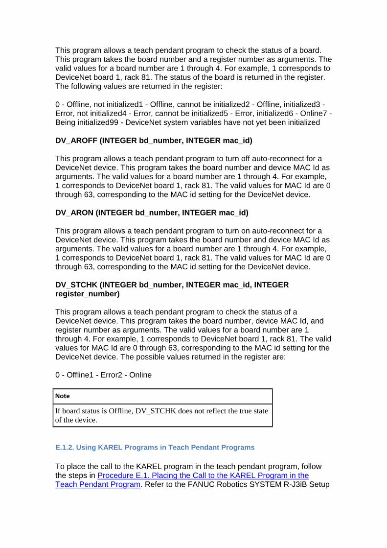
This program allows a teach pendant program to check the status of a board. This program takes the board number and a register number as arguments. The valid values for a board number are 1 through 4. For example, 1 corresponds to DeviceNet board 1, rack 81. The status of the board is returned in the register. The following values are returned in the register:
0 - Offline, not initialized1 - Offline, cannot be initialized2 - Offline, initialized3 - Error, not initialized4 - Error, cannot be initialized5 - Error, initialized6 - Online7 - Being initialized99 - DeviceNet system variables have not yet been initialized
DV_AROFF (INTEGER bd_number, INTEGER mac_id)
This program allows a teach pendant program to turn off auto-reconnect for a DeviceNet device. This program takes the board number and device MAC Id as arguments. The valid values for a board number are 1 through 4. For example, 1 corresponds to DeviceNet board 1, rack 81. The valid values for MAC Id are 0 through 63, corresponding to the MAC id setting for the DeviceNet device.
DV_ARON (INTEGER bd_number, INTEGER mac_id)
This program allows a teach pendant program to turn on auto-reconnect for a DeviceNet device. This program takes the board number and device MAC Id as arguments. The valid values for a board number are 1 through 4. For example, 1 corresponds to DeviceNet board 1, rack 81. The valid values for MAC Id are 0 through 63, corresponding to the MAC id setting for the DeviceNet device.
DV_STCHK (INTEGER bd_number, INTEGER mac_id, INTEGE R register_number)
This program allows a teach pendant program to check the status of a DeviceNet device. This program takes the board number, device MAC Id, and register number as arguments. The valid values for a board number are 1 through 4. For example, 1 corresponds to DeviceNet board 1, rack 81. The valid values for MAC Id are 0 through 63, corresponding to the MAC id setting for the DeviceNet device. The possible values returned in the register are:
0 - Offline1 - Error2 - Online
Note
If board status is Offline, DV_STCHK does not reflect the true state of the device.
E.1.2. Using KAREL Programs in Teach Pendant Progra ms
To place the call to the KAREL program in the teach pendant program, follow the steps in Procedure E.1. Placing the Call to the KAREL Program in the Teach Pendant Program. Refer to the FANUC Robotics SYSTEM R-J3iB Setup
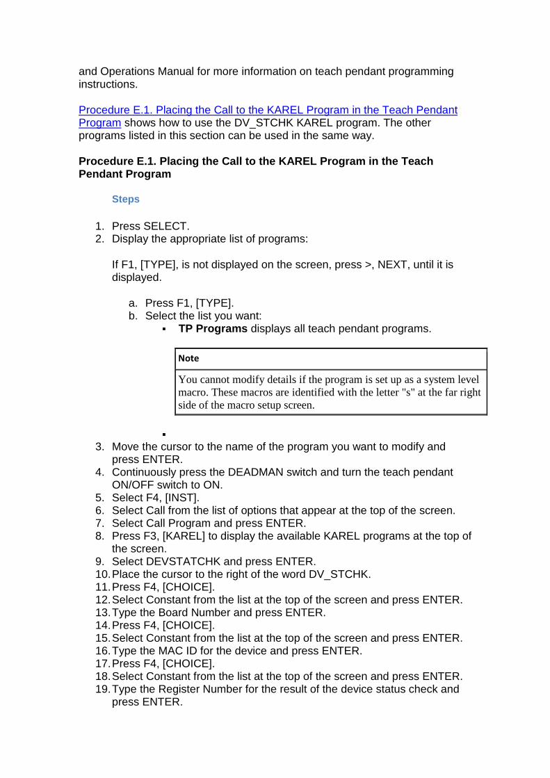
and Operations Manual for more information on teach pendant programming instructions.
Procedure E.1. Placing the Call to the KAREL Program in the Teach Pendant Program shows how to use the DV_STCHK KAREL program. The other programs listed in this section can be used in the same way.
Procedure E.1. Placing the Call to the KAREL Progra m in the Teach Pendant Program
Steps
1. Press SELECT. 2. Display the appropriate list of programs:
If F1, [TYPE], is not displayed on the screen, press >, NEXT, until it is displayed.
a. Press F1, [TYPE]. b. Select the list you want:
� TP Programs displays all teach pendant programs.
Note
You cannot modify details if the program is set up as a system level macro. These macros are identified with the letter "s" at the far right side of the macro setup screen.
� 3. Move the cursor to the name of the program you want to modify and
press ENTER. 4. Continuously press the DEADMAN switch and turn the teach pendant
ON/OFF switch to ON. 5. Select F4, [INST]. 6. Select Call from the list of options that appear at the top of the screen. 7. Select Call Program and press ENTER. 8. Press F3, [KAREL] to display the available KAREL programs at the top of
the screen. 9. Select DEVSTATCHK and press ENTER. 10. Place the cursor to the right of the word DV_STCHK. 11. Press F4, [CHOICE]. 12. Select Constant from the list at the top of the screen and press ENTER. 13. Type the Board Number and press ENTER. 14. Press F4, [CHOICE]. 15. Select Constant from the list at the top of the screen and press ENTER. 16. Type the MAC ID for the device and press ENTER. 17. Press F4, [CHOICE]. 18. Select Constant from the list at the top of the screen and press ENTER. 19. Type the Register Number for the result of the device status check and
press ENTER.
The finished line in the teach pendant program should look like the following:
CALL DV_STCHK (2,55,10)
Note
10 is the register number for result.
Glossary
A abort
Abnormal termination of a computer program caused by hardware or software malfunction or operator cancellation.
absolute pulse code system
A positional information system for servomotors that relies on battery-backed RAM to store encoder pulse counts when the robot is turned off. This system is calibrated when it is turned on.
A/D value
An analog to digital-value. Converts a multilevel analog electrical system pattern into a digital bit.
AI
Analog input.
AO
Analog output.
alarm
The difference in value between actual response and desired response in the performance of a controlled machine, system or process. Alarm=Error.
algorithm
A fixed step-by-step procedure for accomplishing a given result.
alphanumeric
Data that are both alphabetical and numeric.
AMPS
Amperage amount.
analog
The representation of numerical quantities by measurable quantities such as length, voltage or resistance. Also refers to analog type I/O blocks and distinguishes them from discrete I/O blocks. Numerical data that can vary continuously, for example, voltage levels that can vary within the range of -10 to +10 volts.
AND
An operation that places two contacts or groups of contacts in series. All contacts in series control the resulting status and also mathematical operator.
ANSI
American National Standard Institute, the U.S. government organization with responsibility for the development and announcement of technical data standards.
APC
See absolute pulse code system.
APC motor
See servomotor.
application program
The set of instructions that defines the specific intended tasks of robots and robot systems to make them reprogrammable and multifunctional. You can initiate and change these programs.
arm
A robot component consisting of an interconnecting set of links and powered joints that move and support the wrist socket and end effector.
articulated arm
A robot arm constructed to simulate the human arm, consisting of a series of rotary motions and joints, each powered by a motor.
ASCII
Abbreviation for American Standard Code for Information Interchange. An 8-level code (7 bits plus 1 parity bit) commonly used for the exchange of data.
automatic mode
The robot state in which automatic operation can be initiated.
automatic operation
The time during which robots are performing programmed tasks through unattended program execution.
axis
1. A straight line about which a robot joint rotates or moves. 2. One of the reference lines or a coordinate system. 3. A single joint on the robot arm.
B backplane
A group of connectors mounted at the back of a controller rack to which printed circuit boards are mated.
BAR
A unit of pressure equal to 100,000 pascals.
barrier
A means of physically separating persons from the restricted work envelope; any physical boundary to a hazard or electrical device/component.
battery low alarm
A programmable value (in engineering units) against which the analog input signal automatically is compared on Genius I/O blocks. A fault is indicated if the input value is equal to or less than the low alarm value.
baud
A unit of transmission speed equal to the number of code elements (bits) per second.
binary
A numbering system that uses only 0 and 1.
bit
Contraction of binary digit. 1. The smallest unit of information in the binary numbering system, represented by a 0 or 1. 2. The smallest division of a programmable controller word.
bps
Bits per second.
buffer
A storage area in the computer where data is held temporarily until the computer can process it.
bus
A channel along which data can be sent.
bus controller
A Genius bus interface board for a programmable controller.
bus scan
One complete communications cycle on the serial bus.
Bus Switching Module
A device that switches a block cluster to one bus or the other of a dual bus.
byte
A sequence of binary digits that can be used to store a value from 0 to 255 and usually operated upon as a unit. Consists of eight bits used to store two numeric or one alpha character.
C calibration
The process whereby the joint angle of each axis is calculated from a known reference point.
Cartesian coordinate system
A coordinate system whose axes (x, y, and z) are three intersecting perpendicular straight lines. The origin is the intersection of the axes.
Cartesian coordinates
A set of three numbers that defines the location of a point within a rectilinear coordinate system and consisting of three perpendicular axes (x, y, z).
cathode ray tube
A device, like a television set, for displaying information.
central processing unit
The main computer component that is made up of a control section and an arithmetic-logic section. The other basic units of a computer system are input/output units and primary storage.
channel
The device along which data flow between the input/output units of a computer and primary storage.
character
One of a set of elements that can be arranged in ordered groups to express information. Each character has two forms: 1. a man-intelligible form, the graphic, including the decimal digits 0-9, the letters A-Z, punctuation marks, and other formatting and control symbols; 2. a computer intelligible form, the code, consisting of a group of binary digits (bits).
circular
A MOTYPE option in which the robot tool center point moves in an arc defined by three points. These points can be positions or path nodes.
clear
To replace information in a storage unit by zero (or blank, in some machines).
closed loop
A control system that uses feedback. An open loop control system does not use feedback.
C-MOS RAM
Complementary metal-oxide semiconductor random-access memory. A read/write memory in which the basic memory cell is a pair of MOS (metal-oxide semiconductor) transistors. It is an implementation of S-RAM that has very low power consumption, but might be less dense than other S-RAM implementations.
coaxial cable
A transmission line in which one conductor is centered inside and insulated from an outer metal tube that serves as the second conductor. Also known as coax, coaxial line, coaxial transmission line, concentric cable, concentric line, concentric transmission line.
component
An inclusive term used to identify a raw material, ingredient, part or subassembly that goes into a higher level of assembly, compound or other item.
computer
A device capable of accepting information, applying prescribed processes to the information, and supplying the results of these processes.
configuration
The joint positions of a robot and turn number of wrist that describe the robot at a specified position. Configuration is designated by a STRING value and is included in positional data for the R-J3i B system.
continuous path
A trajectory control system that enables the robot arm to move at a constant tip velocity through a series of predefined locations. A rounding effect of the path is required as the tip tries to pass through these locations.
controller memory
A medium in which data are retained. Primary storage refers to the internal area where the data and program instructions are stored for active use, as opposed to auxiliary or external storage (magnetic tape, disk, diskette, and so forth.)
continuous process control
The use of transducers (sensors) to monitor a process and make automatic changes in operations through the design of appropriate feedback control loops. While such devices historically have been
mechanical or electromechanical, microcomputers and centralized control is now used, as well.
continuous production
A production system in which the productive equipment is organized and sequenced according to the steps involved to produce the product. Denotes that material flow is continuous during the production process. The routing of the jobs is fixed and set-ups are seldom changed.
controlled stop
A controlled stop controls robot deceleration until it stops. When a safety stop input such as a safety fence signal is opened, the robot decelerates in a controlled manner and then stops. After the robot stops, the Motor Control Contactor opens and drive power is removed.
controller
A hardware unit that contains the power supply, operator controls, control circuitry, and memory that directs the operation and motion of the robot and communications with external devices. See control unit.
control, open-loop
An operation where the computer applies control directly to the process without manual intervention.
control unit
The portion of a computer that directs the automatic operation of the computer, interprets computer instructions, and initiates the proper signals to the other computer circuits to execute instructions.
coordinate system
See Cartesian coordinate system.
CPU
See central processing unit.
CRT
See cathode ray tube.
CRT/KB
Cathode ray tube/keyboard. An optional interface device for the R-J3i B robot system. The CRT/KB is used for some robot operations and for entering programs. It can be a remote device that attaches to the robot via a cable.
cycle
1. A sequence of operations that is repeated regularly. The time it takes for one such sequence to occur. 2. The interval of time during which a system or process, such as seasonal demand or a manufacturing operation, periodically returns to similar initial conditions. 3. The interval of time during which an event or set of events is completed. In production control, a cycle is the length of time between the release of a manufacturing order and shipment to the customer or inventory.
cycle time
1. In industrial engineering, the time between completion of two discrete units of production. 2. In materials management, the length of time from when material enters a production facility until it exits. See throughput.
cursor
An indicator on a teach pendant or CRT display screen at which command entry or editing occurs. The indicator can be a highlighted field or an arrow (> or ^).
cylindrical
Type of work envelope that has two linear major axes and one rotational major axis. Robotic device that has a predominantly cylindrical work envelope due to its design. Typically has fewer than 6 joints and typically has only 1 linear axis.
D D/A converter
A digital-to-analog converter. A device that transforms digital data into analog data.
D/A value
A digital-to-analog value. Converts a digital bit pattern into a multilevel analog electrical system.
daisy chain
A means of connecting devices (readers, printers, etc.) to a central processor by party-line input/output buses that join these devices by
male and female connectors. The last female connector is shorted by a suitable line termination.
daisy chain configuration
A communications link formed by daisy chain connection of twisted pair wire.
data
A collection of facts, numeric and alphabetical characters, or any representation of information that is suitable for communication and processing.
data base
A data file philosophy designed to establish the independence of computer program from data files. Redundancy is minimized and data elements can be added to, or deleted from, the file designs without changing the existing computer programs.
DC
Abbreviation for direct current.
DEADMAN switch
A control switch on the teach pendant that is used to enable servo power. Pressing the DEADMAN switch while the teach pendant is on activates servo power and releases the robot brakes; releasing the switch deactivates servo power and applies the robot brakes.
debugging
The process of detecting, locating and removing mistakes from a computer program, or manufacturing control system. See diagnostic routine.
deceleration tolerance
The specification of the percentage of deceleration that must be completed before a motion is considered finished and another motion can begin.
default
The value, display, function or program automatically selected if you have not specified a choice.
deviation
Usually, the absolute difference between a number and the mean of a set of numbers, or between a forecast value and the actual data.
device
Any type of control hardware, such as an emergency-stop button, selector switch, control pendant, relay, solenoid valve, or sensor.
diagnostic routine
A test program used to detect and identify hardware/software malfunctions in the controller and its associated I/O equipment. See debugging.
diagnostics
Information that permits the identification and evaluation of robot and peripheral device conditions.
digital
A description of any data that is expressed in numerical format. Also, having the states On and Off only.
digital control
The use of a digital computer to perform processing and control tasks in a manner that is more accurate and less expensive than an analog control system.
digital signal
A single point control signal sent to or from the controller. The signal represents one of two states: ON (TRUE, 1. or OFF (FALSE, 0).
directory
A listing of the files stored on a device.
discrete
Consisting of individual, distinct entities such as bits, characters, circuits, or circuit components. Also refers to ON/OFF type I/O blocks.
disk
A secondary memory device in which information is stored on a magnetically sensitive, rotating disk.
disk memory
A non-programmable, bulk-storage, random-access memory consisting of a magnetized coating on one or both sides of a rotating thin circular plate.
drive power
The energy source or sources for the robot servomotors that produce motion.
D-RAM
Dynamic Random Access Memory. A read/write memory in which the basic memory cell is a capacitor. D-RAM tends to have a higher density than S-RAM. Due to the support circuitry required, and power consumption needs, it is generally impractical to use. A battery can be used to retain the content upon loss of power.
E edit
1. A software mode that allows creation or alteration of a program. 2. To modify the form or format of data, for example, to insert or delete characters.
emergency stop
The operation of a circuit using hardware-based components that overrides all other robot controls, removes drive power from the actuators, and causes all moving parts of to stop. The operator panel and teach pendant are each equipped with EMERGENCY STOP buttons.
enabling device
A manually operated device that, when continuously activated, permits motion. Releasing the device stops the motion of the robot and associated equipment that might present a hazard.
encoder
1. A device within the robot that sends the controller information about where the robot is. 2. A transducer used to convert position data into electrical signals. The robot system uses an incremental optical encoder to provide position feedback for each joint. Velocity data is computed from the encoder signals and used as an additional feedback signal to assure servo stability.
end effector
An accessory device or tool specifically designed for attachment to the robot wrist or tool mounting plate to enable the robot to perform its
intended tasks. Examples include gripper, spot weld gun, arc weld gun, spray paint gun, etc.
end-of-arm tooling
Any of a number of tools, such as welding guns, torches, bells, paint spraying devices, attached to the faceplate of the robot wrist. Also called end effector or EOAT.
engineering units
Units of measure as applied to a process variable, for example, psi, Degrees F., etc.
envelope, maximum
The volume of space encompassing the maximum designed movements of all robot parts including the end effector, workpiece, and attachments.
EOAT
See end of arm tooling, tool.
EPROM
Erasable Programmable Read Only Memory. Semiconductor memory that can be erased and reprogrammed. A non-volatile storage memory.
error
The difference in value between actual response and desired response in the performance of a controlled machine, system or process. Alarm=Error.
error message
A numbered message, displayed on the CRT/KB and teach pendant, that indicates a system problem or warns of a potential problem.
Ethernet
A Local Area Network (LAN) bus-oriented, hardware technology that is used to connect computers, printers, terminal concentrators (servers), and many other devices together. It consists of a master cable and connection devices at each machine on the cable that allow the various devices to "talk" to each other. Software that can access the Ethernet and cooperate with machines connected to the cable is necessary. Ethernets come in varieties such as baseband and broadband and can run on different media, such as coax, twisted pair and fiber. Ethernet is a trademark of Xerox Corporation.
execute
To perform a specific operation, such as one that would be accomplished through processing one statement or command, a series of statements or commands, or a complete program or command procedure.
extended axis
An optional, servo-controlled axis that provides extended reach capability for a robot, including in-booth rail, single- or double-link arm, also used to control motion of positioning devices.
F faceplate
The tool mounting plate of the robot.
feedback
1. The signal or data fed back to a commanding unit from a controlled machine or process to denote its response to the command signal. The signal representing the difference between actual response and desired response that is used by the commanding unit to improve performance of the controlled machine or process. 2. The flow of information back into the control system so that actual performance can be compared with planned performance, for instance in a servo system.
field
A specified area of a record used for a particular category of data. 2. A group of related items that occupy the same space on a CRT/KB screen or teach pendant LCD screen. Field name is the name of the field; field items are the members of the group.
field devices
User-supplied devices that provide information to the PLC (inputs: push buttons, limit switches, relay contacts, an so forth) or perform PLC tasks (outputs: motor starters, solenoids, indicator lights, and so forth.)
file
1. An organized collection of records that can be stored or retrieved by name. 2. The storage device on which these records are kept, such as bubble memory or disk.
filter
A device to suppress interference that would appear as noise.
Flash File Storage
A portion of FROM memory that functions as a separate storage device. Any file can be stored on the FROM disk.
Flash ROM
Flash Read Only Memory. Flash ROM is not battery-backed memory but it is non-volatile. All data in Flash ROM is saved even after you turn off and turn on the robot.
flow chart
A systems analysis tool to graphically show a procedure in which symbols are used to represent operations, data, flow, and equipment. See block diagram, process chart.
flow control
A specific production control system that is based primarily on setting production rates and feeding work into production to meet the planned rates, then following it through production to make sure that it is moving. This concept is most successful in repetitive production.
format
To set up or prepare a memory card or floppy disk so it can be used to store data in a specific system.
FR
See Flash ROM.
F-ROM
See Flash ROM.
FROM disk
See Flash ROM.
G general override stat
A percentage value that governs the maximum robot jog speed and program run speed.
Genius I/O bus
The serial bus that provides communications between blocks, controllers, and other devices in the system especially with respect to GE FANUC Genius I/O.
gripper
The "hand" of a robot that picks up, holds and releases the part or object being handled. Sometimes referred to as a manipulator. See EOAT, tool.
group signal
An input/output signal that has a variable number of digital signals, recognized and taken as a group.
gun
See applicator.
H Hand Model.
Used in Interference Checking, the Hand Model is the set of virtual model elements (spheres and cylinders) that are used to represent the location and shape of the end of arm tooling with respect to the robot's faceplate.
hardware
1. In data processing, the mechanical, magnetic, electrical and electronic devices of which a computer, controller, robot, or panel is built. 2. In manufacturing, relatively standard items such as nuts, bolts, washers, clips, and so forth.
hard-wire
To connect electric components with solid metallic wires.
hard-wired
1. Having a fixed wired program or control system built in by the manufacturer and not subject to change by programming. 2. Interconnection of electrical and electronic devices directly through physical wiring.
hazardous motion
Unintended or unexpected robot motion that can cause injury.
hexadecimal
A numbering system having 16 as the base and represented by the digits 0 through 9, and A through F.
hold
A smoothly decelerated stopping of all robot movement and a pause of program execution. Power is maintained on the robot and program execution generally can be resumed from a hold.
HTML.
Hypertext Markup Language. A markup language that is used to create hypertext and hypermedia documents incorporating text, graphics, sound, video, and hyperlinks.
http.
Hypertext transfer protocol. The protocol used to transfer HTML files between web servers.
I impedance
A measure of the total opposition to current flow in an electrical circuit.
incremental encoder system
A positional information system for servomotors that requires calibrating the robot by moving it to a known reference position (indicated by limit switches) each time the robot is turned on or calibration is lost due to an error condition.
index
An integer used to specify the location of information within a table or program.
index register
A memory device containing an index.
industrial robot
A reprogrammable multifunctional manipulator designed to move material, parts, tools, or specialized devices through variable programmed motions in order to perform a variety of tasks.
industrial robot system
A system that includes industrial robots, end effectors, any equipment devices and sensors required for the robot to perform its tasks, as well as communication interfaces for interlocking, sequencing, or monitoring the robot.
information
The meaning derived from data that have been arranged and displayed in a way that they relate to that which is already known. See data.
initialize
1. Setting all variable areas of a computer program or routine to their desired initial status, generally done the first time the code is executed during each run. 2. A program or hardware circuit that returns a program a system, or hardware device to an original state. See startup, initial.
input
The data supplied from an external device to a computer for processing. The device used to accomplish this transfer of data.
input device
A device such as a terminal keyboard that, through mechanical or electrical action, converts data from the form in which it has been received into electronic signals that can be interpreted by the CPU or programmable controller. Examples are limit switches, push buttons, pressure switches, digital encoders, and analog devices.
input processing time
The time required for input data to reach the microprocessor.
input/output
Information or signals transferred between devices, discreet electrical signals for external control.
input/output control
A technique for controlling capacity where the actual output from a work center is compared with the planned output developed by CRP. The input is also monitored to see if it corresponds with plans so that work centers will not be expected to generate output when jobs are not available to work on.
integrated circuit
A solid-state micro-circuit contained entirely within a chip of semiconductor material, generally silicon. Also called chip.
interactive
Refers to applications where you communicate with a computer program via a terminal by entering data and receiving responses from the computer.
interface
1. A concept that involves the specifications of the inter-connection between two equipments having different functions. 2. To connects a PLC with the application device, communications channel, and peripherals through various modules and cables. 3. The method or equipment used to communicate between devices.
interference zone
An area that falls within the work envelope of a robot, in which there is the potential for the robot motion to coincide with the motion of another robot or machine, and for a collision to occur.
interlock
An arrangement whereby the operation of one control or mechanism brings about, or prevents, the operations of another.
interrupt
A break in the normal flow of a system or program that occurs in a way that the flow can be resumed from that point at a later time. Interrupts are initiated by two types of signals: 1. signals originating within the computer system to synchronize the operation of the computer system with the outside world; 2. signals originating exterior to the computer system to synchronize the operation of the computer system with the outside world.
I/O
Abbreviation for input/output or input/output control.
I/O block
A microprocessor-based, configurable, rugged solid state device to which field I/O devices are attached.
I/O electrical isolation
A method of separating field wiring from logic level circuitry. This is typically done through optical isolation devices.
I/O module
A printed circuit assembly that is the interface between user devices and the Series Six PLC.
I/O scan
A method by which the CPU monitors all inputs and controls all outputs within a prescribed time. A period during which each device on the bus is given a turn to send information and listen to all of the broadcast data on the bus.
ISO
The International Standards Organization that establishes the ISO interface standards.
isolation
1. The ability of a logic circuit having more than one inputs to ensure that each input signal is not affected by any of the others. 2. A method of separating field wiring circuitry from logic level circuitry, typically done optically.
item
1. A category displayed on the teach pendant on a menu. 2. A set of adjacent digits, bits, or characters that is treated as a unit and conveys a single unit of information. 3. Any unique manufactured or purchased part or assembly: end product, assembly, subassembly, component, or raw material.
J jog coordinate systems
Coordinate systems that help you to move the robot more effectively for a specific application. These systems include JOINT, WORLD, TOOL, and USER.
JOG FRAME
A jog coordinate system you define to make the robot jog the best way possible for a specific application. This can be different from world coordinate frame.
jogging
Pressing special keys on the teach pendant to move the robot.
jog speed
Is a percentage of the maximum speed at which you can jog the robot.
joint
1. A single axis of rotation. There are up to six joints in a robot arm (P-155 swing arm has 8). 2. A jog coordinate system in which one axis is moved at a time.
JOINT
A motion type in which the robot moves the appropriate combination of axes independently to reach a point most efficiently. (Point to point, non-linear motion).
joint interpolated motion
A method of coordinating the movement of the joints so all joints arrive at the desired location at the same time. This method of servo control produces a predictable path regardless of speed and results in the fastest cycle time for a particular move. Also called joint motion.
K K
Abbreviation for kilo, or exactly 1024 in computer jargon. Related to 1024 words of memory.
KAREL
The programming language developed for robots by the FANUC Robotics North America, Inc.
L label
An ordered set of characters used to symbolically identify an instruction, a program, a quantity, or a data area.
LCD
See liquid crystal display.
lead time
The span of time needed to perform an activity. In the production and inventory control context, this activity is normally the procurement of materials and/or products either from an outside supplier or from one's own manufacturing facility. Components of lead time can include order
preparation time, queue time, move or transportation time, receiving and inspection time.
LED
See Light Emitting Diode.
LED display
An alphanumeric display that consists of an array of LEDs.
Light Emitting Diode
A solid-state device that lights to indicate a signal on electronic equipment.
limiting device
A device that restricts the work envelope by stopping or causing to stop all robot motion and that is independent of the control program and the application programs.
limit switch
A switch that is actuated by some part or motion of a machine or equipment to alter the electrical circuit associated with it. It can be used for position detection.
linear
A motion type in which the appropriate combination of axes move in order to move the robot TCP in a straight line while maintaining tool center point orientation.
liquid crystal display
A digital display on the teach pendant that consists of two sheets of glass separated by a sealed-in, normally transparent, liquid crystal material. Abbreviated LCD.
load
1. The weight (force) applied to the end of the robot arm. 2. A device intentionally placed in a circuit or connected to a machine or apparatus to absorb power and convert it into the desired useful form. 3. To copy programs or data into memory storage.
location
1. A storage position in memory uniquely specified by an address. 2. The coordinates of an object used in describing its x, y, and z position in a Cartesian coordinate system.
lockout/tagout
The placement of a lock and/or tag on the energy isolating device (power disconnecting device) in the off or open position. This indicates that the energy isolating device or the equipment being controlled will not be operated until the lock/tag is removed.
log
A record of values and/or action for a given function.
logic
A fixed set of responses (outputs) to various external conditions (inputs). Also referred to as the program.
loop
The repeated execution of a series of instructions for a fixed number of times, or until interrupted by the operator.
M mA
See milliampere.
machine language
A language written in a series of bits that are understandable by, and therefore instruct, a computer. This is a "first level" computer language, as compared to a "second level" assembly language, or a "third level" compiler language.
machine lock
A test run option that allows the operator to run a program without having the robot move.
macro
A source language instruction from which many machine-language instructions can be generated.
magnetic disk
A metal or plastic floppy disk that looks like a phonograph record whose surface can store data in the form of magnetized spots.
magnetic disk storage
A storage device or system consisting of magnetically coated metal disks.
magnetic tape
Plastic tape, like that used in tape recorder, on which data is stored in the form of magnetized spots.
maintenance
Keeping the robots and system in their proper operating condition.
MC
See memory card.
mechanical unit
The robot arm, including auxiliary axis, and hood/deck and door openers.
medium
plural media . The physical substance upon which data is recorded, such as a memory card or floppy disk.
memory
A device or media used to store information in a form that can be retrieved and is understood by the computer or controller hardware. Memory on the R-J3i B system includes C-MOS RAM, Flash ROM and D-RAM.
memory card
A C-MOS RAM memory card or a flash disk-based PC card.
menu
A list of options displayed on the teach pendant screen.
message
A group of words, variable in length, transporting an item of information.
microprocessor
A single integrated circuit that contains the arithmetic, logic, register, control and memory elements of a computer.
microsecond
One millionth (0.000001) of a second
milliampere
One one-thousandth of an ampere. Abbreviated mA.
millisecond
One thousandth of a second. Abbreviated msec.
module
A distinct and identifiable unit of computer program for such purposes as compiling, loading, and linkage editing. It is eventually combined with other units to form a complete program.
motion type
A feature that allows you to select how you want the robot to move from one point to the next. MOTYPES include joint, linear, and circular.
mode
1. One of several alternative conditions or methods of operation of a device. 2. The most common or frequent value in a group of values.
N network
1. The interconnection of a number of devices by data communication facilities. "Local networking" is the communications network internal to a robot. "Global networking" is the ability to provide communications connections outside of the robot's internal system. 2. Connection of geographically separated computers and/or terminals over communications lines. The control of transmission is managed by a standard protocol.
non-volatile memory
Memory capable of retaining its stored information when power is turned off.
O Obstacle Model.
Used in Interference Checking, the Obstacle Model is the set of virtual model elements (spheres, cylinders, and planes) that are used to represent the shape and the location of a given obstacle in space.
off-line
Equipment or devices that are not directly connected to a communications line.
off-line operations
Data processing operations that are handled outside of the regular computer program. For example, the computer might generate a report off-line while the computer was doing another job.
off-line programming
The development of programs on a computer system that is independent of the "on-board" control of the robot. The resulting programs can be copied into the robot controller memory.
offset
The count value output from a A/D converter resulting from a zero input analog voltage. Used to correct subsequent non-zero measurements also incremental position or frame adjustment value.
on-line
A term to describe equipment or devices that are connected to the communications line.
on-line processing
A data processing approach where transactions are entered into the computer directly, as they occur.
operating system
Lowest level system monitor program.
operating work envelope
The portion of the restricted work envelope that is actually used by the robot while it is performing its programmed motion. This includes the maximum the end-effector, the workpiece, and the robot itself.
operator
A person designated to start, monitor, and stop the intended productive operation of a robot or robot system.
operator box
A control panel that is separate from the robot and is designed as part of the R-J3i B system. It consists of the buttons, switches, and indicator lights needed to operate the system.
operator panel
A control panel designed as part of the R-J3i B system and consisting of the buttons, switches, and indicator lights needed to operate the system.
optional features
Additional capabilities available at a cost above the base price.
OR
An operation that places two contacts or groups of contacts in parallel. Any of the contacts can control the resultant status, also a mathematical operation.
orientation
The attitude of an object in space. Commonly described by three angles: rotation about x (w), rotation about y (p), and rotation about z (r).
origin
The point in a Cartesian coordinate system where axes intersect; the reference point that defines the location of a frame.
OT
See overtravel.
output
Information that is transferred from the CPU for control of external devices or processes.
output device
A device, such as starter motors, solenoids, that receive data from the programmable controller.
output module
An I/O module that converts logic levels within the CPU to a usable output signal for controlling a machine or process .
outputs
Signals, typically on or off, that controls external devices based upon commands from the CPU.
override
See general override.
overtravel
A condition that occurs when the motion of a robot axis exceeds its prescribed limits.
overwrite
To replace the contents of one file with the contents of another file when copying.
P parity
The anticipated state, odd or even, of a set of binary digits.
parity bit
A binary digit added to an array of bits to make the sum of all bits always odd or always even.
parity check
A check that tests whether the number of ones (or zeros) in an array of binary digits is odd or even.
parity error
A condition that occurs when a computed parity check does not agree with the parity bit.
part
A material item that is used as a component and is not an assembly or subassembly.
pascal
A unit of pressure in the meter-kilogram-second system equivalent to one newton per square meter.
path
1. A variable type available in the KAREL system that consists of a list of positions. Each node includes positional information and associated data. 2. The trajectory followed by the TCP in a move.
PCB
See printed circuit board.
PC Interface
The PC Interface software uses Ethernet connections to provide file transfer protocol (FTP) functions, PC send macros, telnet interface, TCP/IP interface web server functions, and host communications.
pendant
See teach pendant.
PLC
See programmable logic controller or cell controller.
PMC
The programmable machine controller (PMC) functions provide a ladder logic programming environment to create PMC functions. This provides the capability to use the robot I/O system to run PLC programs in the background of normal robot operations. This function can be used to control bulk supply systems, fixed automation that is part of the robot workcell, or other devices that would normally require basic PLC controls.
printed circuit board
A flat board whose front contains slots for integrated circuit chips and connections for a variety of electronic components, and whose back is printed with electrically conductive pathways between the components.
production mode
See automatic mode.
program
1. A plan for the solution of a problem. A complete program includes plans for the transcription of data, coding for the computer, and plans for the absorption of the results into the system. 2. A sequence of instructions to be executed by the computer or controller to control a robot/robot system. 3. To furnish a computer with a code of instructions. 4. To teach a robot system a specific set of movements and instructions to do a task.
programmable controller
See programmable logic controller or cell controller.
programmable logic controller
A solid-state industrial control device that receives inputs from user-supplied control devices, such as switches and sensors, implements them in a precise pattern determined by ladder diagram-based programs stored in the user memory, and provides outputs for control of processes or user-supplied devices such as relays and motor starters.
Program ToolBox
The Program ToolBox software provides programming utilities such as mirror image and flip wrist editing capabilities.
protocol
A set of hardware and software interfaces in a terminal or computer that allows it to transmit over a communications network, and that collectively forms a communications language.
PSI
Pounds per square inch.
Q queue.
1. Waiting lines resulting from temporary delays in providing service. 2. The amount of time a job waits at a work center before set-up or work is performed on the job. See also job queue.
R RAM
See Random Access Memory.
random access
A term that describes files that do not have to be searched sequentially to find a particular record but can be addressed directly.
Random Access Memory
1. Volatile, solid-state memory used for storage of programs and locations; battery backup is required. 2. The working memory of the controller. Programs and variable data must be loaded into RAM before the program can execute or the data can be accessed by the program.
range
1. A characterization of a variable or function. All the values that a function can possess. 2. In statistics, the spread in a series of observations. 3. A programmable voltage or current spectrum of values to which input or output analog signals can be limited.
RI
Robot input.
RO
Robot output.
read
To copy, usually from one form of storage to another, particularly from external or secondary storage to internal storage. To sense the meaning of arrangements of hardware. To sense the presence of information on a recording medium.
Read Only Memory
A digital memory containing a fixed pattern of bits that you cannot alter.
record
To store the current set or sets of information on a storage device.
recovery
The restoration of normal processing after a hardware or software malfunction through detailed procedures for file backup, file restoration, and transaction logging.
register
1. A special section of primary storage in a computer where data is held while it is being worked on. 2. A memory device capable of containing one or more computer bits or words.
remote/local
A device connection to a given computer, with remote devices being attached over communications lines and local devices attached directly to a computer channel; in a network, the computer can be a remote device to the CPU controlling the network.
repair
To restore robots and robot systems to operating condition after damage, malfunction, or wear.
repeatability
The closeness of agreement among the number of consecutive movements made by the robot arm to a specific point.
reset
To return a register or storage location to zero or to a specified initial condition.
restricted work envelope
That portion of the work envelope to which a robot is restricted by limiting devices that establish limits that will not be exceeded in the event of any reasonably foreseeable failure of the robot or its controls. The maximum distance the robot can travel after the limited device is actuated defines the restricted work envelope of the robot.
RIA
Robotic Industries Association Subcommittee of the American National Standards Institute, Inc.
robot
A reprogrammable multifunctional manipulator designed to move material, parts, tools, or specialized devices, through variable programmed motions for the performance of a variety of tasks.
Robot Model.
Used in Interference Checking, the Robot Model is the set of virtual model elements (sphere and cylinders) that are used to represent the location and shape of the robot arm with respect to the robot's base.
Generally, the structure of a six axes robot can be accurately modeled as a series of cylinders and spheres. Each model element represents a link or part of the robot arm.
ROM
See Read Only Memory.
routine
1. A list of coded instructions in a program. 2. A series of computer instructions that performs a specific task and can be executed as often as needed during program execution.
S saving data.
Storing program data in Flash ROM, to a floppy disk, or memory card.
scratch start
Allows you to enable and disable the automatic recovery function.
SI
System input.
SO
System output.
sensor
A device that responds to physical stimuli, such as heat, light, sound pressure, magnetism, or motion, and transmits the resulting signal or data for providing a measurement, operating a control or both. Also a device that is used to measure or adjust differences in voltage in order to control sophisticated machinery dynamically.
serial communication
A method of data transfer within a PLC whereby the bits are handled sequentially rather than simultaneously as in parallel transmission.
serial interface
A method of data transmission that permits transmitting a single bit at a time through a single line. Used where high speed input is not necessary.
Server Side Include (SSI)
A method of calling or "including" code into a web page.
servomotor
An electric motor that is controlled to produce precision motion. Also called a "smart" motor.
signal
The event, phenomenon, or electrical quantity that conveys information from one point to another.
significant bit
A bit that contributes to the precision of a number. These are counted starting with the bit that contributes the most value, of "most significant bit," and ending with the bit that contributes the least value, or "least significant bit."
slip sheet
A sheet of material placed between certain layers of a unit load. Also known as tier sheet.
specific gravity
The ratio of a mass of solid or liquid to the mass of an equal volume of water at 45C. You must know the specific gravity of the dispensing material to perform volume signal calibration. The specific gravity of a dispensing material is listed on the MSDS for that material.
S-RAM
A read/write memory in which the basic memory cell is a transistor. S-RAM tends to have a lower density than D-RAM. A battery can be used to retain the content upon loss of power.
Standard Operator Panel (SOP).
A panel that is made up of buttons, keyswitches, and connector ports.
state
The on or off condition of current to and from and input or output device.
statement
See instruction.
storage device
Any device that can accept, retain, and read back one or more times. The available storage devices are S-RAM, Flash ROM (FROM or F-ROM), floppy disks, and memory cards.
system variable
An element that stores data used by the R-J3i B system to indicate such things as robot specifications, application requirements, and the current status of the system.
T Tare
The difference between the gross weight of an object and its contents, and the object itself. The weight of an object without its contents.
TCP
See tool center point.
teaching
Generating and storing a series of positional data points effected by moving the robot arm through a path of intended motions.
teach mode
1. The mode of operation in which a robot is instructed in its motions, usually by guiding it through these motions using a teach pendant. 2. The generation and storage of positional data. Positional data can be taught using the teach pendant to move the robot through a series of positions and recording those positions for use by an application program.
teach pendant
1. A hand-held device used to instruct a robot, specifying the character and types of motions it is to undertake. Also known as teach box, teach gun. 2. A portable device, consisting of an LCD display and a keypad, that serves as a user interface to the KAREL system and attaches to the operator box or operator panel via a cable. The teach pendant is used for robot operations such as jogging the robot, teaching and recording positions, and testing and debugging programs.
telemetry
The method of transmission of measurements made by an instrument or a sensor to a remote location.
termination type
Feature that controls the blending of robot motion between segments.
tool
A term used loosely to define something mounted on the end of the robot arm, for example, a hand, gripper, or an arc welding torch.
tool center point
1. The location on the end-effector or tool of a robot hand whose position and orientation define the coordinates of the controlled object. 2. Reference point for position control, that is, the point on the tool that is used to teach positions. Abbreviated TCP.
TOOL Frame
The Cartesian coordinate system that has the position of the TCP as its origin to stet. The z-axis of the tool frame indicates the approach vector for the tool.
TP.
See teach pendant.
transducer
A device for converting energy from one form to another.
U UOP
See user operator panel.
URL
Universal Resource Locator. A standard addressing scheme used to locate or reference files on web servers.
USER Frame
The Cartesian coordinate system that you can define for a specific application. The default value of the User Frame is the World Frame. All positional data is recorded relative to User Frame.
User Operator Panel
User-supplied control device used in place of or in parallel with the operator panel or operator box supplied with the controller. Abbreviated UOP .
V variable
A quantity that can assume any of a given set of values.
variance
The difference between the expected (or planned) and the actual, also statistics definitions.
vision system
A device that collects data and forms an image that can be interpreted by a robot computer to determine the position or to "see" an object.
volatile memory
Memory that will lose the information stored in it if power is removed from the memory circuit device.
W web server
An application that allows you to access files on the robot using a standard web browser.
warning device
An audible or visible device used to alert personnel to potential safety hazards.
work envelope
The volume of space that encloses the maximum designed reach of the robot manipulator including the end effector, the workpiece, and the robot itself. The work envelope can be reduced or restricted by limiting devices. The maximum distance the robot can travel after the limit device is actuated is considered the basis for defining the restricted work envelope.
write
To deliver data to a medium such as storage.