development of window films for solar shading and...
TRANSCRIPT

SEI TECHNICAL REVIEW · NUMBER 74 · APRIL 2012 · 95
1. Introduction
In response to a growing awareness of energy-savingand power-saving and the need for improving the living en-vironment near windows, the applications of transparentheat ray blocking films that can be affixed to window glasshave been proposed.
We have promoted the development of optical func-tional films by combining our technologies of optical multi-layered membrane design, precision coating, and elongatedsputtering, as well as material technology. We report herethe development of transparent window films for solarshading and heat insulating applications which meet themarket needs mentioned above very well.
2. Outline of the Development
2-1 Functions of the solar shading and heat insulatingwindow filmsAs windows are required to ensure natural lighting and
views, solar-shading and heat-insulating window films need tosimultaneously pursue those goals while maintaining trans-parency. Figure 1 shows the distribution of sunlight energy ac-cording to light wavelength, the distribution of warming radiantheat energy from indoors, the transmission and reflection spec-trum that is required for window-affixed films to produce trans-parency, heat shielding (solar shading), and heat insulatingfunctions. To enable windows to balance the maintenance oflighting and sunlight-energy-shielding, it is necessary to formcut-off filters that transmit visible light (wavelength: 0.4 to0.8µm) and reflect near-infrared light (wavelength: 0.8 to 2µm)out of sunlight energy. Moreover, because the heat insulationfunctions are produced by reducing thermal discharge throughthe reflection of far-infrared light (wavelength 5 to 20µm),which is warming radiant heat energy from indoors, to the in-door side, the reflection of far-infrared light is also required.
Tokai Rubber Industries, Ltd. (TRI) has developed window films for solar shading and heat insulating applications bycombining its advanced technologies of optical multi-layered membrane design, precision coating, and elongatedsputtering, as well as material technology. The optical functional membrane is a multi-layered membrane that consistsof thin Ag alloy membranes and thin dielectric membranes with a high refractive index. TRI has significantly reduced thecost of manufacturing the dielectric membranes by using its original sol-gel wet film forming method, and hasaccordingly succeeded in producing competitively-priced optical function membranes. The solar shading and heatinsulating effects of the films were proven in the verification tests by using the experimental equipment of TokyoUniversity of Science. Furthermore, the energy-saving effects for annual air-conditioning-related power consumptionwere estimated by using the thermal load calculation program “LESCOM-wind” in a model office.
Keywords: window film, solar shading, heat insulating, infrared light, sol-gel
Development of Window Films for Solar Shading andHeat Insulating Applications
Tetsuya TAKEUCHI*, Osamu GOTO, Masataka INUDUKA, Tetsuji NARASAKI,
Yoshihiro TOKUNAGA, Hisami BESSHO and Hitoshi TAKEDA*
ENVIRONMENT, ENERGY & RESOURCES
0.2 0.4 0.6 0.8 1.0 1.2 1.4 1.6 1.8 2.0
Wavelength (μm)
Wavelength (μm)
Energ
y (mWc
m-2 · μ
m-1 )200
100
0
150
50
250 Ultraviolet light Visible light
Infrared light (heat rays)
5.0 10 20 50
Sunlight energy Radiant energy from indoorsRadiant energy from indoorsRadiant energy from indoors
0.2 0.4 0.6 0.8 1.0 1.2 1.4 1.6 1.8 2.0
Ultraviolet light Reflectance
5.0 10 20 50Trans
mitta
nce, r
eflec
tance
(%)
Transmittance
Infrared light (heat rays)
Distribution of sunlight and indoor radiant energy
Optical characteristics sought for filmsVisible light
Fig. 1. Distribution of sunlight and indoor radiant heat energy, and optical characteristics sought for window-affixed films
GlassIndoors
Reflection of sunlight heat
(near-infrared light)
Reflection of warming heat(far-infrared light)
Visible lighttransmission
Window film
Window film
Visible lighttransmission
GlassIndoors
SummerHeat shielding (solar shading)
WinterHeat insulating
Fig. 2. Functions of solar shading and heat insulating films

Figure 2 shows the image of the functions of solarshading and heat insulating films in the summer and thewinter.2-2 Design and composition of functional membranes
When designing the functional membranes as opticalmulti-layered membrane filters, which can meet all de-mands for visible light transmission, near-infrared light re-flection and far-infrared light reflection, we have selectedAg alloy membranes that absorb little visible light andlargely reflect infrared light, as the layer possessing a lowrefractive index. Additionally, we have secured naturallighting and views by making the reflectance low and thetransmittance high in the invisible light region throughmulti-layering of the alloy membranes and thin dielectricmembranes possessing a high refractive index. Accordingto the width of transparent wavelength in the required vis-ible light region, starting inclination of the reflectance inthe near-infrared light region and reflectance in the far-in-frared light region, the number of layers made by thin di-electric membranes with high refractive index and Agmembranes, as well as the membrane thickness of eachlayer, are decided. Figure 3 shows the cross section photoof a seven-layered film.
The actual films are composed of thin dielectric mem-branes with high refractive index and Ag alloy membranes,alternately laminated on the PET film; several nm-thick Timembranes are inserted into the interface between thethin dielectric membrane with high refractive index andthe Ag membrane to limit Ag migration and enhance plyadhesion.2-3 Technology of adding heat insulating functions
To add heat insulating functions, it is necessary to re-flect warming heat (far-infrared light) generated from in-doors to the indoor side without absorbing it. Conventionalsolar shading films, however, have no heat insulating func-tions because the PET film and acrylic hard coating areplaced on the indoor side of functional membranes (heatray reflective coating), and the films in that combinationabsorb warming heat (far-infrared light). Therefore, wehave simultaneously pursued heat insulating properties andabrasion resistance by changing the film composition fromthe glass side to the order of the adhesive layer, PET film,heat ray reflection function membranes, acrylic protectivemembranes and acrylic hard coating and by controlling the
thickness of hard coating membranes and protective mem-branes respectively to the appropriate range of not morethan 1 µm. Figure 4 shows the film compositions of the solarshading and heat insulating type and the solar shading type.
2-4 Functional membranes manufacturing technologyWe have significantly reduced the cost of manufactur-
ing thin dielectric membranes with a high refractive index,which are one component of functional membranes, byusing the wet coating method that ensures high linearspeed in the air, instead of high-cost reactive sputtering filmformation. Made by using organic titanate as the material,the membranes are coated by the gravure roll method, and,after being dried, they are subjected to a low-temperaturesol-gel polymerization reaction by UV irradiation, whichmakes the formation of titanium dioxide (TiO2) on the PETfilm possible. Considering stability in coating fluid, the easeof producing a high refractive index and the unlikelinessof generating cracks, we have used n-butoxytitanium (mul-timer) for organic titanate, which is chelated by acetylace-tone to add UV absorbency. Figure 5 shows the mechanismof the UV assist sol-gel polymerization reaction.
96 · Development of Window Films for Solar Shading and Heat Insulating Applications
High refractive indexdielectric substance (sol-gel)-coated membrane
PET film
Approx. 200nm
Metal (Ti/Ag/Ti) sputtering membrane
Functionalm
embranes
Fig. 3. Sectional structure (TEM image) of the functional membrane
FunctionSolar
shadingHeat
insulatingFilm composition (cross section)
Sola
r sha
ding
and
he
at in
sula
ting
type
Sola
r sha
ding
type
×
outdoorsindoors
indoorsoutdoors
Glass
Adhesive layer
Protective membrane Hard coating
Reflectionof sunlightheat (near-infrared)
No reflectionof warmingheat(far-infrared)
Glass
Adhesive layer
Protective membrane Hard coating
Functional membranes (heat ray reflective membrane)
Reflectionof sunlightheat (near-infrared)
Reflectionof warming heat(far-infrared)
PETfilm
PETfilm
Functional membranes (heat ray reflective membrane)
Fig. 4. Structure of the solar shading and heat insulating films
TiRO O R
OR
OR
CH2C CO O
CH33HC
n
+TiRO O R
OR OR n
CHC C
O O
CH33HC
Hydrolysis Condensation
Ti O Ti O Ti O
Ti O Ti O Ti OO O O
n-butoxytitanium (multimer) AcetylacetoneUV absorbent
chelateCoating, drying, UV irradiation
TiO2 thin film R: Butyl group
Fig. 5. Mechanism of UV assist sol-gel polymerization reaction

3. Characteristics of the Solar Shading and HeatInsulating Films
3-1 Optical characteristicsWe have developed three types of window films for
solar shading and heating insulating applications: “Refle-shine TX71” with solar shading functions, “Refle-shineTW31” with heat insulating functions, and “Refle-shineTU71” with solar shading and heat insulating functions.Figures 6 to 8 show the transmission and reflection spec-trum in the ultraviolet to the far-infrared light region. Eachfigure, respectively, shows that the solar shading film“Refle-shine TX71” has visible light transmission and near-infrared light reflection functions; that the heat insulatingfilm “Refle-shine TW31” has visible light transmission andfar-infrared light reflection functions; and that the solarshading and heat insulating film “Refle-shine TU71” has
visible light transmission and near-infrared light to far-in-frared light reflection functions.
Table 1 shows the characteristics of “Refle-shine TX71”,“Refle-shine TW31” and “Refle-shine TU71”. The three typesof film ensure good lighting with more than 70% of visiblelight transmittance. TX71 and TU71 ensure high solar shad-ing with a shading coefficient of not higher than 0.6. Also,TW31 and TU71 ensure good heat insulation with the over-all heat transfer coefficient of not more than 4.5 W/m2K. Inparticular, TU71 is the world's first film that ensures trans-parency, solar shading and heat insulating characteristics.
3-2 Weather resistanceBased on JISA5759 “Films for building window glass,”
films for building windows should be subjected to the weather
SEI TECHNICAL REVIEW · NUMBER 74 · APRIL 2012 · 97
0
20
40
60
80
100
0.1 1 10 100
Wavelength (µm)
Trans
mitta
nce,
reflec
tance
(%)
Transmission spectrum Reflection spectrum
Fig. 6. Transmission and reflection spectrum of the solar shading film “Refle-shine TX71”
0
20
40
60
80
100
0.1 1 10 100
Wavelength (µm)
Trans
mitta
nce,
reflec
tance
(%)
Transmission spectrum Reflection spectrum
Fig. 7. Transmission and reflection spectrum of the heat insulating film “Refle-shine TW31”
0
20
40
60
80
100
0.1 1 10 100
Wavelength (µm)
Trans
mitta
nce,
reflec
tance
(%)
Transmission spectrumReflection spectrum
Fig. 8. Transmission and reflection spectrum of the solar shading and heat insulating film “Refle-shine TU71”
Table 1. Characteristics of “Refle-shine TX71”, “Refle-shine TW31” and “Refle-shine TU71”
Table 2. Weather resistant test conditions
Solar shadingtype
Heat insulating type
Solar shadingand heat insu-lating type
Reference
Refle-shineTX71
Refle-shineTW31
Refle-shineTU71
Only 3mm-thickplate glass
Lighting Visible light transmittance
71.0% 81.6% 70.8% 90.4%
Solar shadingShading coefficient 0.57 0.74 0.51 1.00
Solar transmittance 39.6% 61.0% 37.0% 87.4%
Heat insulating
Overall heat transfer coefficient
5.77W/m2K 4.49W/m2K 4.47W/m2K 5.92W/m2K
Safety of glassagainst heatcracking
Solar absorptance 32.4% 19.0% 34.1% 4.4%
Test method: Measured by affixing the films to 3mm-thick plate glass, based onJISA5759 “Films for building window glass”
Item Condition
Light source
Sunshine carbon-arc lamp: 1 unitLight filterSpectral transmittanceNot more than 2% at 275nmNot less than 90% at 400nm
Power supply voltage
Conditions for irradiation
Mean discharge voltage of power source
Temperature indicated by black panel thermometer
Relative humidity
Irradiance on the surface of specimen
AC 200V±20V
50V±1V, 60A±1.2A
63˚C±3˚C
(50±5)%
255 (±10%) W/m2 (at 300nm to 700nm)
Water jetting Normally, water is jetted for 18 minutes during 120 minutes of irradiation.
Film-affixed glassSpectral transmittanceNot more than 2% at 275nmNot less than 90% at 400nm
Conditions of photoirradiation to specimen
Affixed with the glass surface facingthe light source.
Method of water jetting Water is jetted to the glass surface onthe photo-irradiation side.

resistant test by using a weatherometer of the sunshine car-bon-arc lamp type. Table 2 shows the test conditions.
Table 3 shows the test results of “Refle-shine TX71”,“Refle-shine TW31” and “Refle-shine TU71.” The resultsconfirmed that there were no changes in appearance andoptical characteristics of the three films after 1,000 hourshad passed since the start of the test.
4. Experimental Verification of the Solar Shadingand Heat Insulating Effects
4-1 Experimental methodologyWe have verified the thermal effects of the developed
solar shading and heat insulating films by using the experi-mental equipment of Tokyo University of Science. Photo 1shows the experimental equipment.
There are six units of experimental equipment (here-inafter referred to as ”test box”), of which four units were
used. The test box has an opening, 1 m wide and 2 m highon the southern side, to which single plate glass or multi-ple-layer glass is installed. Heat insulation is applied bypolystyrene foam, 100 mm thick, to all parts of the testboxes, except the glass surface. Among the four test boxes,solar shading and heat insulating films were affixed to theinside of the glass for three units, while the remaining unitwas left with nothing affixed to the glass for comparison.Using a PC and data logger, we performed the experimentsby measuring the air temperature in the test boxes, tem-perature inside the glass, and the amount of transmittedsolar radiation at intervals of one minute for 24 consecutivehours. Figure 9 shows the installation of sensors in the testboxes. When measuring heat insulating effects, 400 W far-infrared ray heaters were installed, facing the polystyrenefoam side opposite the glass surface in each test box andthe on/off control of the heaters was simultaneously per-formed in the all test boxes, to maintain a temperature be-tween 20˚C and 25˚C with the air temperature at a heightof 150 cm from the floor, within the glass-only test box asthe standard(1), (2).
Regarding solar shading and heat insulating effects,using single plate glass or multiple-layer glass for the open-ing of the test box, the comparison was made respectivelybetween the situation of affixing solar shading and heat in-sulating films to the glass and a control setup using glass
98 · Development of Window Films for Solar Shading and Heat Insulating Applications
Table 3. Comparison of the characteristics of “Refle-shine TX71,” “Refle-shine TW31” and “Refle-shine TU71” before and after the test
Type Item Initial stage After weather resistant test
Solar shadingtype TX71
Visible light transmittance 71.0% 71.8%
Shading coefficient 0.57 0.56
Solar transmittance 39.6% 39.2%
Overall heat transfer coefficient 5.77W/m2K 5.79W/m2K
Solar absorptance 32.4% 31.8%
Heat insulatingtypeTW31
Visible light transmittance 81.6% 79.4%
Shading coefficient 0.74 0.74
Solar transmittance 61.0% 60.0%
Overall heat transfer coefficient 4.49W/m2K 4.63W/m2K
Solar absorptance 19.0% 20.4%
Solarshadingand heat
insulatingtypeTU71
Visible light transmittance 70.8% 71.6%
Shading coefficient 0.51 0.54
Solar transmittance 37.0% 37.8%
Overall heat transfer coefficient 4.47W/m2K 4.52W/m2K
Solar absorptance 34.1% 30.4%
Photo 1. Experimental equipment
FrontActinometer
Side cross section
Air temperature in the box
Glass surface temperature in the box
Long and short wave radiometer Heater
Heat generationside
The heater is used only when measuring heat insulating effects
Fig. 9. Installation of sensors in the test box
Table 4. List of experiments performed
Used glass Season Test date
Verificationof solar
shading effects
Single plateglass
8mm thick
Winter to interim period February 3 to 20, 2011
Summer June 28 to July 31, 2011
Multiple-layerglass
8/A6/8mm
Winter to interim period April 2 to 30, 2011
Summer June 1 to 26, 2011
Verificationof heat
insulatingeffects
Single plateglass
8mm thick
Winter to interim period March 14 to 15, 2011
Summer —
Multiple-layerglass
8/A6/8mm
Winter to interim period April 7 to 8, 2011
Summer —

only. The experiments were performed from the winterthrough the interim period and in the summer. Table 4shows the list of experiments performed.4-2 Experimental results(1) Verification of solar shading effects(a) When affixed to single plate glass
Figure 10 shows the temporal fluctuation of air tem-perature in the box when the films were affixed to the in-side of the 8mm-thick single plate glass. They are theresults on February 5 to 7, 2011 in the winter and the in-terim period, and the results on July 12 to 14, 2011 in thesummer. When the experiments were performed, meteor-ological data were also simultaneously measured. As an ex-ample, Fig. 11 shows the data of outdoor air temperatureand vertical intensity of solar radiation in the winter andthe interim period and the summer experimental period.
In the measurements made in the winter and the in-terim period, February 5 and 6 were cloudy and on Febru-ary 7 there was fine weather. In the measurements madein the summer, July 12 and 13 were cloudy and on July 14there was fine weather. When there was sunlight, the airtemperature in the box fell by up to 12.9˚C for TU71,11.9˚C for TX71 and 4.8˚C for TW31 in the winter and3.9˚C for TU71, 4.1˚C for TX71, and 0.6˚C for TW31 in thesummer, compared with the box with only glass installedwith no films. It is confirmed from the results that therewere temperature rise restraining effects when the filmswere affixed to the glass and that the smaller the shadingcoefficient was, the larger the temperature rise restrainingeffects were.
In addition, the rising of air temperature in the boxwas lower in the summer than in the winter. This is becausethe vertical intensity of solar radiation on the southernside, where the opening was installed, is smaller in the sum-mer, which decreases the amount of solar radiation flowinginto the box.(b) When affixed to multiple-layer glass
Figure 12 shows the temporal fluctuation of air tem-perature in the box when TU71 was affixed to the insideof the multiple-layer glass [glass 8 mm / air 6 mm / glass 8mm]. The measurement in the case when the LowE multi-ple-layer glass of the same thickness (shading coefficient0.69, overall heat transfer coefficient 2.5 W/m2K) was usedwas simultaneously made for comparison. These are the re-sults from April 14 to 16, 2011, in the winter and the in-terim period and the results from June 5 to 7, 2011, in thesummer. In the measurements made in the winter and theinterim period, on April 14 and 15 there was fine weatherand April 16 was cloudy. In the measurements made in thesummer, June 5 and 7 were cloudy and on June 6 there wasfine weather.
The air temperature in the box fell by up to 7.4˚C forTU71 and 4.3˚C for the LowE multiple-layer glass in thewinter and the interim period and 2.9˚C for TU71 and1.2˚C for the LowE multiple-layer glass in the summer,compared with the box where only multiple-layer glass wasinstalled with no films. From the above-mentioned results,even in the case of multiple-layer glass, it is confirmed thatthere were temperature rise restraining effects when thefilms were affixed to the glass and that, the smaller theshading coefficient was, the larger the temperature rise re-
SEI TECHNICAL REVIEW · NUMBER 74 · APRIL 2012 · 99
-10
0
10
20
30
40
50
60
70
80
0:00 12:00 0:00 12:00 0:00 12:00 0:00
Air t
empe
ratu
re in
the
box
(℃)
Air t
empe
ratu
re in
the
box
(℃)
2/5 2/6 2/7
Only single plate glassOnly single plate glassTW31 affixedTW31 affixedTX71 affixedTX71 affixed
TU71 affixedTU71 affixed
45
47
49
51
53
55
57
59
61
63
65
6:00 7:12 8:24 9:36 10:48 12:00 13:12 14:24 15:36 16:48 18:00
Only single plate glassOnly single plate glass
TW31 affixedTW31 affixed
TX71 affixedTX71 affixed
TU71 affixedTU71 affixed
Only single plate glassTW31 affixedTX71 affixed
TU71 affixed
Only single plate glass
TW31 affixed
TX71 affixed
TU71 affixed
Partial enlargement of Feb.7
-10
0
10
20
30
40
50
60
70
80
0:00 12:00 0:00 12:00 0:00 12:00 0:00
7/12 7/13 7/14
Only single plate glassOnly single plate glass
TU71 affixedTU71 affixed
TW31 affixedTW31 affixedTX71 affixedTX71 affixed
Air t
empe
ratu
re in
the
box
(℃)
46
47
48
49
50
51
52
53
54
6:00 7:12 8:24 9:36 10:48 12:00 13:12 14:24 15:36 16:48 18:00
Only single plate glassOnly single plate glass
TW31 affixedTW31 affixed
TX71 affixedTX71 affixed
TU71 affixedTU71 affixed
Only single plate glass
TU71 affixed
TW31 affixedTX71 affixed
Only single plate glass
TW31 affixed
TX71 affixed
TU71 affixed
Air t
empe
ratu
re in
the
box
(℃) Partial enlargement
of July 14
(1) Experiments in the winter to the interim period
(2) Experiments in the summer
Fig. 10. Temporal fluctuation of air temperature in the box in (1) the experiments in the winter to the interim period and (2) the experiments in the summer (in the case of single plate glass)

straining effects were.(2) Verification of heat insulating effects(a) When affixed to the single plate glass
The experiments in the cases where the heat insulat-ing type TW31 and the solar shading type TX71 were af-fixed to the inside of the 8mm-thick single plate glass, wereperformed between March 14 and 15, 2011. The experi-ments were performed at night to avoid the effects of heatfrom sunlight. Figure 13 shows the temporal fluctuation ofthe air temperature in the box. Moreover, Fig. 14 showsthe data of outdoor air temperature and the vertical inten-sity of solar radiation during the experimental period.
400 W far-infrared ray heaters were installed in eachtest box and the on/off control of the heaters was simulta-neously performed in the all test boxes, to maintain a tem-perature between 20˚C and 25˚C with the air temperatureat a height of 150 cm from the floor within the glass-onlytest box as the standard. The air temperature in the box re-peats in a rising and falling waveform. When the heat insu-lating type TW31 was affixed to the glass, the temperature
100 · Development of Window Films for Solar Shading and Heat Insulating Applications
-10-50510152025303540
0:00 12:00 0:00 12:00 0:00 12:00 0:00Outdo
or air
temp
eratur
e (˚C) 2/5 2/6 2/7
0
200
400
600
800
0:00 12:00 0:00 12:00 0:00 12:00 0:00Vertica
l inten
sity of
solar r
adiatio
n (W/m2 )
2/5 2/6 2/7
Outdo
or air
temp
eratur
e (˚C)
Vertica
l inten
sity of
solar r
adiatio
n (W/m2 )
05101520253035404550
0:00 12:00 0:00 12:00 0:00 12:00 0:00
7/12 7/13 7/14
0
200
400
600
800
0:00 12:00 0:00 12:00 0:00 12:00 0:00
7/13 7/147/12
(2) Meteorological data of the experiments in the summer
(1) Meteorological data of the experiments in the winter to the interim period
Fig. 11. Examples of the meteorological data during the experimental periods
-10
0
10
20
30
40
50
60
70
80
0:00 12:00 0:00 12:00 0:00 12:00 0:00
Only multipleOnly multiple-layer glass-layer glass
TU71 affixedTU71 affixed
LowE multipleLowE multiple-layer glass-layer glass
Air t
empe
ratu
re in
the
box
(˚C)
Air t
empe
ratu
re in
the
box
(˚C)
4/14 4/15 4/16
54
56
58
60
62
64
66
68
6:00 7:12 8:24 9:36 10:48 12:00 13:12 14:24 15:36 16:48 18:00
Only multiple-layer glassOnly multiple-layer glass
TU71 affixedTU71 affixed
LowE multiple-layer glassLowE multiple-layer glass
Partial enlargement of April 14
-10
0
10
20
30
40
50
60
70
80
0:00 12:00 0:00 12:00 0:00 12:00 0:00
6/5 6/6 6/7
Only multiple-layer glassOnly multiple-layer glass
TU71 affixedTU71 affixed
LowE multiple-layer glassLowE multiple-layer glass
Air t
empe
ratu
re in
the
box
(˚C)
Air t
empe
ratu
re in
the
box
(˚C)
40
41
42
43
44
45
46
47
48
49
50
6:00 7:12 8:24 9:36 10:48 12:00 13:12 14:24 15:36 16:48 18:00
Only multiple-layer glassOnly multiple-layer glass
TU71 affixedTU71 affixed
LowE multiple-layer glassLowE multiple-layer glass
Only multiple-layer glass
TU71 affixed
LowE multiple-layer glass
Only multiple-layer glass
TU71 affixed
LowE multiple-layer glass
Only multiple-layer glass
TU71 affixed
LowE multiple-layer glass
Only multiple-layer glass
TU71 affixed
LowE multiple-layer glass
Partial enlargement of June 6
(1) Experiments in the winter to the interim period
(2) Experiments in the summer
Fig. 12. (1) Temporal fluctuation of air temperature in the box in (1) the experiments in the winter to the interim period and (2) the experiments in the summer (in the case of multiple-layer glass)
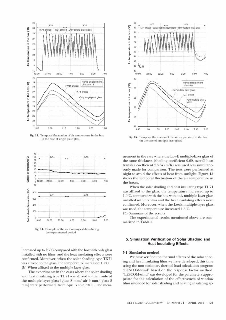
increased up to 2.7˚C compared with the box with only glassinstalled with no films, and the heat insulating effects wereconfirmed. Moreover, when the solar shading type TX71was affixed to the glass, the temperature increased 1.1˚C.(b) When affixed to the multiple-layer glass
The experiments in the cases where the solar shadingand heat insulating type TU71 was affixed to the inside ofthe multiple-layer glass [glass 8 mm/ air 6 mm/ glass 8mm] were performed from April 7 to 8, 2011. The meas-
urement in the case where the LowE multiple-layer glass ofthe same thickness (shading coefficient 0.69, overall heattransfer coefficient 2.5 W/m2K) was used was simultane-ously made for comparison. The tests were performed atnight to avoid the effects of heat from sunlight. Figure 15shows the temporal fluctuation of the air temperature inthe boxes.
When the solar shading and heat insulating type TU71was affixed to the glass, the temperature increased up to1.0˚C, compared with the box with only multiple-layer glassinstalled with no films and the heat insulating effects wereconfirmed. Moreover, when the LowE multiple-layer glasswas used, the temperature increased 1.5˚C.(3) Summary of the results
The experimental results mentioned above are sum-marized in Table 5.
5. Simulation Verification of Solar Shading andHeat Insulating Effects
5-1 Simulation methodWe have verified the thermal effects of the solar shad-
ing and heat insulating films we have developed, this timeusing the non-stationary thermal-load calculation program“LESCOM-wind” based on the response factor method.“LESCOM-wind” was developed for the parameters appro-priate for the calculation of the effectiveness of windowfilms intended for solar shading and heating insulating ap-
SEI TECHNICAL REVIEW · NUMBER 74 · APRIL 2012 · 101
15
17
19
21
23
25
27
29
31
33
19:00 21:00 23:00 1:00 3:00 5:00 7:00
Only single plate glassTW31 affixedTX71 affixed3/14 3/15
20
21
22
23
24
25
26
27
28
29
30
1:05 1:10 1:15 1:20 1:25 1:30
Only single plate glassOnly single plate glass
TW31 affixedTW31 affixed
TX71 affixedTX71 affixed
Only single plate glass
TW31 affixed
TX71 affixed
Air t
empe
ratu
re in
the
box
(˚C)
Air t
empe
ratu
re in
the
box
(˚C) Partial enlargement
of March 15
Fig. 13. Temporal fluctuation of air temperature in the box (in the case of single plate glass)
15
17
19
21
23
25
27
29
31
33
35
19:00 21:00 23:00 1:00 3:00 5:00 7:00
TU71 affixed LowE multiple-layer glass Only multiple-layer glass4/7 4/8
Air t
empe
ratu
re in
the
box
(˚C)
Air t
empe
ratu
re in
the
box
(˚C)
22
24
26
28
30
32
1:45 1:50 1:55 2:00 2:05 2:10 2:15 2:20
TU71 affixed
LowE multiple-layer glass
Only multiple-layer glass
Partial enlargement of April 8
Fig. 15. Temporal fluctuation of the air temperature in the box (in the case of multiple-layer glass)
-10-50510152025303540
19:00 21:00 23:00 1:00 3:00 5:00 7:00Outdo
or air
temp
eratur
e (˚C) 3/14 3/15
3/14 3/15
0
200
400
600
800
19:00 21:00 23:00 1:00 3:00 5:00 7:00Vertica
l inten
sity of
solar r
adiatio
n (W/m2 )
Fig. 14. Example of the meteorological data during the experimental period

plications, based on the multi-room non-stationary thermalload calculation program “LESCOM,” developed by thetask force for “living function enhancement products” ofthe former Ministry of International Trade and Industry,Consumer Goods Industries Bureau(3)-(6).
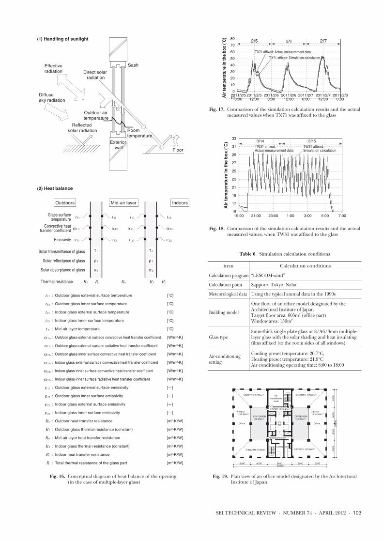
Figure 16 shows the conceptual diagram of heat bal-ance of the opening, which is extremely complicated andwide-ranging. The non-stationary thermal load calculationprogram “LESCOM-wind” reproduces the thermal envi-ronment by computer simulation, based on a thermal equi-librium formula in consideration of such heat balance.5-2 Results of simulation verification(1) Verification of solar shading effects
We have verified the solar shading effects by perform-ing the simulation calculation, namely; the thermal loadcalculation based on the actual test box experiments, usingthe thermal load calculation program “LESCOM-wind.”The calculation was performed based on the solar shadingexperiments using the 8 mm-thick single plate glass, whichwere performed from February 5 to 7, 2011, by using themeteorological data of the relevant days. Figure 17 showsthe simulation calculation results and the actual measure-ment data of the air temperatures in the box when TX71was affixed to the glass. The simulation calculation resultsusing “LESCOM-wind” conformed to the actual measure-ment data very well and the solar shading effects of TX71were also confirmed by the simulation calculation.(2) Verification of heat insulating effects
As in the case of (1), using the thermal load calcula-tion program “LESCOM-wind,” the simulation calculationwas performed based on the heat insulating experimentsconducted on March 14 and 15, 2011, using the 8 mm-thick single plate glass and the meteorological data of therelevant days. Figure 18 shows the simulation calculationresults and the actual measurement data of the air temper-atures in the box when TW31 was affixed to the glass. The
simulation calculation results using “LESCOM-wind” con-formed to the actual measurement data very well, and theheat insulating effects of TW31 were also confirmed by thesimulation calculation.
6. Air-Conditioning Load Simulation in a Model Office
6-1 Simulation methodAs it was confirmed that the calculation results con-
formed well to the experimental results in the test boxes,using the thermal load calculation program “LESCOM-wind,” we have performed the simulation calculation of en-ergy-saving effects for annual air-conditioning-relatedpower consumption in the case where solar shading andheat insulating films were used in a model office desig-nated by the Architectural Institute of Japan. The calcula-tions were performed in three locations— Sapporo, Tokyo,and Naha. Table 6 shows the simulation calculation condi-tions, while Fig. 19 shows the plan view of a model officedesignated by the Architectural Institute of Japan(7).6-2 Simulation results
Figure 20 shows the annual air-conditioning-relatedpower consumption when TU71, TW31, and TX71 wererespectively affixed to the 8 mm-thick single plate glass. Fig-ure 21 shows the annual air-conditioning-related powerconsumption when TU71 was affixed to the multiple-layerglass [glass 8 mm / air 6 mm / glass 8 mm]. Table 7 showsthe annual air-conditioning-related thermal load in Tokyowhen the films were affixed to the single plate glass. Table8 shows the annual air-conditioning-related thermal loadin Tokyo when the films were affixed to the multiple-layerglass. Figure 21 and Table 8 show the calculation resultswhen the LowE multiple-layer glass of the same thickness
102 · Development of Window Films for Solar Shading and Heat Insulating Applications
Table 5. Summary of the solar shading and heat insulation effects verification experiments
Used glass Season
Effects of affixing the films (Comparison of the difference of air temperature inthe boxes compared with the box with only glass installed with no films) Reference
Standard Solar shading film(TX71) affixed
Heat insulating film(TW31) affixed
Solar shading andheat insulating film(TU71) affixed
LowE multiple-layer glass
Verification of solar shading
effects
Single plateglass
8mm thick
Winter to interim period
Based on thecase of
only single plateglass
11.9˚C down 4.8˚C down 12.9˚C down
Summer 4.1˚C down 0.6˚C down 3.9˚C down
Multiple-layer glass8/A6/8mm
Winter to interim period
Based on thecase of
only multiple-layer glass
- - 7.4˚C down 4.3˚C down
Summer - - 2.9˚C down 1.2˚C down
Verification of heat insulating
effects
Single plateglass
8mm thick
Winter to interim period
Based on thecase of
only single plateglass
1.1˚C up 2.7˚C up -
Summer
Multiple-layer glass8/A6/8mm
Winter to interim period
Based on thecase of
only multiple-layer glass
- - 1.0˚C up 1.5˚C up
Summer
SEI TECHNICAL REVIEW · NUMBER 74 · APRIL 2012 · 103
Direct solar radiation
Effective radiation
Diffuse sky radiation
Reflected solar radiation
Sash
Exterior Exterior wallwall
Exterior wall Floor
Outdoor air temperature
Roomtemperature
Outdoors Mid-air layer Indoors
Glass surface temperature
Solar transmittance of glass
Solar reflectance of glass
Solar absorptance of glass
Convective heat transfer coefficient
Emissivity
Thermal resistance R0 R1 R2Rm Ri
t 11
α11c
ε11
t 12
α12c
ε12
t 21
α21c
ε21
t 22
α22c
ε22
τ1
ρ1
α1
t 11 : Outdoor glass external surface temperature [˚C]
t 12 : Outdoor glass inner surface temperature [˚C]
t 21 : Indoor glass external surface temperature [˚C]
t 22 : Indoor glass inner surface temperature [˚C]
t m : Mid-air layer temperature [˚C]
α11c : Outdoor glass external surface convective heat transfer coefficient [W/m2•K]
α11r : Outdoor glass external surface radiative heat transfer coefficient [W/m2•K]
α12c : Outdoor glass inner surface convective heat transfer coefficient [W/m2•K]
α21c : Indoor glass external surface convective heat transfer coefficient [W/m2•K]
α22c : Indoor glass inner surface convective heat transfer coefficient [W/m2•K]
α22r : Indoor glass inner surface radiative heat transfer coefficient [W/m2•K]
ε11 : Outdoor glass external surface emissivity [—]
ε12 : Outdoor glass inner surface emissivity [—]
ε21 : Indoor glass external surface emissivity [—]
ε22 : Indoor glass inner surface emissivity [—]
R0 : Outdoor heat transfer resistance [m2•K/W]
R1 : Outdoor glass thermal resistance (constant) [m2•K/W]
Rm : Mid-air layer heat transfer resistance [m2•K/W]
R2 : Indoor glass thermal resistance (constant) [m2•K/W]
Ri : Indoor heat transfer resistance [m2•K/W]
R : Total thermal resistance of the glass part [m2•K/W]
(1) Handling of sunlight
(2) Heat balance
τ2
ρ2
α2
Fig. 16. Conceptual diagram of heat balance of the opening (in the case of multiple-layer glass)
-100
1020304050607080
2011/2/50:00
2011/2/512:00
2011/2/60:00
2011/2/612:00
2011/2/70:00
2011/2/712:00
2011/2/80:00
TX71 affixed: Actual measurement dataTX71 affixed: Actual measurement dataTX71 affixed: Simulation calculationTX71 affixed: Simulation calculation
TX71 affixed: Actual measurement dataTX71 affixed: Simulation calculation
Air t
empe
ratu
re in
the b
ox (˚
C) 2/5 2/6 2/7
Fig. 17. Comparison of the simulation calculation results and the actual measured values when TX71 was affixed to the glass
15
17
19
21
23
25
27
29
31
33
19:00 21:00 23:00 1:00 3:00 5:00 7:00
TW31 affixed: TW31 affixed: Actual measurement dataActual measurement data
TX71 affixed: TX71 affixed: Simulation calculationSimulation calculation
TW31 affixed: Actual measurement data
TW31 affixed: Simulation calculation
3/14 3/15
Air t
empe
ratu
re in
the
box
(˚C)
Fig. 18. Comparison of the simulation calculation results and the actual measured values, when TW31 was affixed to the glass
336006300 6000 9000 6000 6300
Air conditioner
room
EVhall
Lavatory
Hot-water service room
Lavatory
Office Office
②SOUTH(57.65m2)③SOUTH(57.65m2)
④WEST(115.29m2)
⑤NORTH(57.65m2) ⑥NORTH(57.65m2)
⑧INTERIOR(72.00m2)
①EAST(115.29m2)
⑦INTERIOR(72.00m2)
⑨CORE(221.40m2)
2460
063
0060
0060
0063
00
Fig. 19. Plan view of an office model designated by the Architectural Institute of Japan
Table 6. Simulation calculation conditions
item Calculation conditions
Calculation program “LESCOM-wind”
Calculation point Sapporo, Tokyo, Naha
Meteorological data Using the typical annual data in the 1990s
Building model
One floor of an office model designated by the Architectural Institute of JapanTarget floor area: 605m2 (office part)Window area: 150m2
Glass type8mm-thick single plate glass or 8/A6/8mm multiple-layer glass with the solar shading and heat insulatingfilms affixed (to the room sides of all windows)
Air-conditioning setting
Cooling preset temperature: 26.7°C,Heating preset temperature: 21.9°CAir conditioning operating time: 8:00 to 18:00

(shading coefficient 0.69, overall heat transfer coefficient2.5 W/m2K) was used, for comparison. The comparison ofthe results for the single plate glass shows that, in all loca-tions — Sapporo, Tokyo, and Naha — affixing the solarshading and heat insulating films to the glass had the ef-fects of reducing the annual air-conditioning-related powerconsumption, compared with the conditions where nofilms were used. In particular, it is confirmed that TU71,which has both solar shading and heat insulating functions,had the largest reduction effects in all the locations. More-over, it is confirmed from the simulation results that affix-ing TU71 to the multiple-layer glass had the reductionresults equivalent to those of the LowE multiple-layer glass(shading coefficient 0.69, overall heat transfer coefficient2.5 W/m2K).
7. Conclusion
We have developed window films for solar shading,heat insulating, and solar shading and heat insulating bycombining our technologies of optical multi-layered mem-brane design, precision coating, and elongated sputtering,as well as making advances in material technology. The op-tical functional membranes consist of membranes alter-nately laminated with the Ag alloy membrane and dielectricmembranes with a high refractive index. In particular, wehave significantly reduced the cost of forming dielectricmembranes with a high refractive index based on our orig-inal sol-gel wet film formation method. Through verifica-tion using the experimental equipment of Tokyo Universityof Science and the simulation verification using the thermalload calculation program “LESCOM-wind,” we have clari-fied the solar shading and heat insulating effects of ourfilms. Moreover, we have calculated the energy-saving ef-fects for annual air-conditioning-related power consump-tion in a model office.
In the future, we aim to develop constituent materialsand make the design of functional membranes more widelyapplicable and are planning to achieve even higher per-formance and greater cost reductions for the films.
104 · Development of Window Films for Solar Shading and Heat Insulating Applications
10,00012,000
14,00016,000
18,00020,00022,000
24,00026,000
28,00030,000
Sapporo Tokyo Naha
Annu
al a
ir-co
nditi
onin
g-re
late
d p
ower
con
sum
ptio
n (k
Wh)
: Only single plate glass : TU71-affixed to single plate glass : TX71-affixed to single plate glass : TW31-affixed to single plate glass
100%92%
99%93% 100%
90% 95% 94%
100%
86%89%
95%
Fig. 20. Calculation results when the films were affixed to the single plate glass
Annu
al a
ir-co
nditi
onin
g-re
late
d p
ower
con
sum
ptio
n (k
Wh)
10,00012,000
14,00016,000
18,00020,00022,000
24,00026,000
28,00030,000
Sapporo Tokyo Naha
100%96% 94% 100%
94% 96%
100%92%
97% : Only multiple-layer glass : TU71-affixed multiple-layer glass : Reference: LowE multiple-layer glass
Fig. 21. Calculation results when the films were affixed to the multiple-layer glass
Annual cooling and heating load
Annual cooling loadkWh/ year
Annual heating loadkWh/ yearkWh/ year Relative ratio
Only single plate glass 17,198 100% 13,028 4,170
TU71-affixed to single plate glass 15,502 90% 11,017 4,485
TX71-affixed to single plate glass 16,332 95% 11,266 5,067
TW31-affixed to single plate glass 16,136 94% 12,360 3,775
Table 7. Calculation results for the annual air-conditioning-related thermal load in Tokyo when the films were affixed to the single plate glass
The relative ratio shows the rate when the air-conditioning-related thermal loadin using the single plate glass was regarded as 100.
Table 8. Calculation results for the annual air-conditioning-related thermal load in Tokyo when the films were affixed to the multiple-layer glass
Annual cooling and heating load
Annual cooling loadkWh/ year
Annual heating loadkWh/ yearkWh/ year Relative ratio
Only multiple-layer glass 15,668 100% 13,056 2,612
TU71-affixed multiple-layer glass 14,726 94% 11,835 2,892
Reference: LowE multiple-layer glass 15,004 96% 12,711 2,293
The relative ratio shows the rate when the air-conditioning-related thermal loadin using the multiple-layer glass was regarded as 100.

Technical Term*1 Shading coefficient: The numerical value that expresses
the heat quantity of sunlight energy inflow, when theindoor inflow heat quantity by the transmissionthrough, and reradiation from, a 3 mm-thick transpar-ent plate glass is 1.00
*2 Overall heat transfer coefficient: The numerical valuethat expresses the heat quantity passing the area of 1 m2
per hour when there is a temperature difference of 1˚C.*3 Glass heat cracking: When a sheet of window glass re-
ceives direct sunlight, the parts exposed to sunlightwarm and expand, but the surrounding parts belowthe sash and shaded parts warm only slightly and re-main at a comparatively low temperature. This low-temperature part restrains the expansion of warmedparts and, as a result, tensile stress occurs in the sur-rounding glass edge. When the stress exceeds edgestrength of the glass, ”heat cracking of the glass” oc-curs.
*4 Cooling load: The amount of energy required for cool-ing a room to a certain temperature.
*5 Heating load: The amount of energy required forwarming a room to a certain temperature.
References(1) Tetsuya Takeuchi, Hitoshi Takeda, Hiroki Inagaki, Hisami Bessho:
The study concerning solar shading and heat insulating effects of thesolar shading films, Part 1, Experimental verification of solar shadingeffects, Digest of academic lectures of the Architectural Institute ofJapan, D-2, pp563-564, 2011
(2) Hiroki Inagaki, Hitoshi Takeda, Tetsuya Takeuchi, Hisami Bessho:The study concerning solar shading and heat insulating effects ofsolar shading films, Part 2, Experimental verification of the heat in-sulating effects of low radiation films, Digest of academic lectures ofthe Architectural Institute of Japan, D-2, pp565-566, 2011
(3) Yo Matsuo, Hitoshi Takeda: The thermal load calculation methodbased on the response factor method and the sample calculation (1),The journal of the Society of Heating, Air-Conditioning and SanitaryEngineers of Japan, Vol.44 No.4, pp1-14, 1970
(4) Yo Matsuo, Hitoshi Takeda: The thermal load calculation methodbased on the response factor method and the sample calculation (2),The journal of the Society of Heating, Air-Conditioning and SanitaryEngineers of Japan, Vol. 44 No.7, pp11-25, 1970
(5) Hitoshi Takeda: Room temperature fluctuation analysis for non-air-conditioned rooms, the collection of papers of the Society of Heat-ing, Air-Conditioning and Sanitary Engineers of Japan, No. 7,pp13-21, 1978
(6) Hitoshi Takeda, Minoru Inanuma, Nozomu Yoshizawa, KyoichiroIsozaki: Standard meteorological data and thermal load calculationprogram, LESCOM, Inoueshoin, 2005
(7) Hiroshi Takizawa: Proposal of typical problems - Typical problemsfor office, Architectural Institute of Japan, Research Committee onEnvironmental Engineering, Documents of the 15th Heat Sympo-sium, pp35-42, 1985
* Refle-shine is a trademark or registered trademark of Tokai Rubber In-dustries, Ltd.
Contributors (The lead author is indicated by an asterisk (*).)
T. TAKEUCHI*• Project Deputy General Manager, NewBusiness R&D Laboratories, Tokai Rub-ber Industries, Ltd.Engaged in the development of opticalfunctional films
O. GOTO• New Business R&D Laboratories, Tokai Rubber Indus-tries, Ltd.
M. INUDUKA• New Business R&D Laboratories, Tokai Rubber Indus-tries, Ltd.
T. NARASAKI• Project Manager, New Business R&D Laboratories,Tokai Rubber Industries, Ltd.
Y. TOKUNAGA• Deputy Manager, Refle-shine Functional Film BusinessUnit, Tokai Rubber Industries, Ltd.
H. BESSHO• General Manager, New Business R&D Laboratories,Tokai Rubber Industries, Ltd.
H. TAKEDA*
• Doctor of Engineering Professor Emeritus, Tokyo University ofScience, Specializes in environmental en-gineering of architecture
SEI TECHNICAL REVIEW · NUMBER 74 · APRIL 2012 · 105