development of solar fluorescent lamp mohd...
TRANSCRIPT
DEVELOPMENT OF SOLAR FLUORESCENT LAMP
MOHD HAFIZUDDIN BIN ABDUL RAZAK
This thesis is submitted in fulfillment of the requirements for the award of the Bachelor Degree of
Electrical Engineering (Power System)
Faculty of Electrical & Electronic Engineering
Universiti Malaysia Pahang
NOVEMBER 2009
“All the trademark and copyright use herein are property of their respective owner.
Reference of information from other sources are quoted accordingly; otherwise the
information presented in this report is solely word of the author,”
Signature : _________________________
Author :MOHD HAFIZUDDIN BIN ABDUL RAZAK
Date :24 NOVEMBER 2009
ACKNOWLEDGEMENT
First of all, I would like to thank God for his bless towards myself. Without
his blessing I could not be able to finish my final year project. My project title is
“Development of Solar Fluorescent Lamp”. I able to complete this project in time of
the requirement of the degree of Bachelor Engineering (Electric Power System).
Secondly, I would like to thank to all people had assisted me either directly or
indirectly in completing my final year project. My special thank to Mr. Ruhaizad B.
Ishak, my intelligent supervisor for the project whom had given her support,
knowledge, advice and also guidance that I need. He had been guiding me from the
beginning of the project until the final thesis has been done. With his support, I had
learned a lot of knowledge regarding to this project, many thing that I can use in my
future especially the experience in making this project. Without him, I not expect that
I will finish this project same as the University requirement. Thank again to Mr.
Ruhaizad.
A million thank also to other lecturers who had teach and helped me in
completing this project. Not to forget, I would like to thank to all my friends in
support and their co-operation especially my roommates. They had never hesitated to
help me in sharing and discuss about this project. May God bless them always,
Amin.
Last but not least, my very special thank to my beloved parents and also to all
my siblings who had given me a support while I was struggling with this project.
ABSTRACT
Solar cells are common examples in this category of electricity generation.
They are also known as photovoltaic cells. A combination of individual PV cells
forms the Photovoltaic module. A collection of photovoltaic modules, which are tied
together with a wire and are so designed to install it in a field readily, is known as
photovoltaic panels or simply solar panels. The installation includes the photovoltaic
modules, an inverter, a battery all linked to each other with a wire.
Since this technology is still new in Malaysia especially in UMP. The using
of solar as electric source is limited. So, in this case, I need to develop a system that
uses solar panel as a basic supply for the Fluorescent Lamp. This project is mainly
concerned in design a charger that uses solar as source to charge the battery 12 V.
This project also designs the inverter from 12VDC to 240VAC. The inverter could
be supply power to the load that we use in this project. The load is a Fluorescent
Lamp. This project will be divided into two main parts which are hardware design
and software development. The hardware includes the charger and the inverter. The
charger will take the energy from the solar source and store it in battery. After that
the battery will give supply to the inverter circuit to convert the direct current into
alternating current. The most important thing in this project is to convert direct
current DC into alternating current AC. By using suitable controller, it will change
from square wave into sine wave. The controller can produce the waveform that we
need. Lastly when we get the suitable power, voltage and current, we connect it to
the Fluorescent Lamp as a load in this project.
ABSTRAK
Sel suria adalah salah satu kategori dalam penghasilan elektrik. Ia juga
dikenali sebagai sel fotovoltan. Kombinasi satu sel PV akan menghasilkan module
fotovoltan. Pengumpulan modul, merangkumi bersama satu rekabentuk yang hendak
dipasang dikenali sebagai panel fotovoltan atau dengan erti kata lain panel suria.
Pemasangan akan dilengkapi dengan panel suria, satu penyongsang, satu bateri and
akan disambung dengan satu wayar.
Walaubagaimanapun, teknologi ini masih baru di Malaysia terutamanya di
UMP. Penggunaan suria elektrik agak terhad. Jadi dalam hal ini, saya perlu mencipta
satu sistem yang menggunakan panel suria sebagai pembekal utama untuk lampu
Fluorescent. Projek ini akan tertumpu pada mencipta pengecas dari sumber suria
untuk mengecas bateri 12 V. Projek ini juga mencipta penyongsang dari 12 NDC
kepada 240 VAC. Penyongsang ini akan membekalkan kuasa kepada beban yang
digunakan. Bebennya adalah lampu Fluorescent. Projek ini akan terbahagi kepada
dua bahagian iaitu “hardware design” dan jalan kira untuk penggunaan kuasa.
“Hardware” akan merangkumi pengecas dan juga penyongsang. Pengecas akan
mengambil kuasa daripada suria dan menyimpannya kedalam bateri. Selepas itu
bateri akan membekalkan kuasa untuk litar penyongsang supaya menukar arus terus
kepada arus ulang alik. Apa yang paling penting dalam projek ini adalah untuk
menukar arus terus DC kepada arus ulang alik AC. Dengan menggunakan pengawal
litar yang sesuai, ia akan menukar “square wave” kepada “sine wave”. Akhir sekali,
bila dapat nilai kuasa, voltan dan arus yang sesuai, sambungkan ia kepada lampu
Fluorescent sebagai beban dalam projek ini.
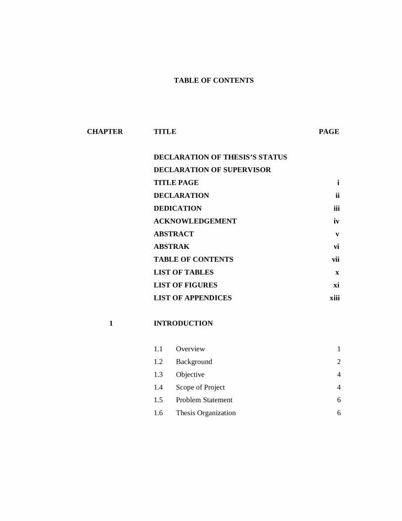
TABLE OF CONTENTS
CHAPTER TITLE PAGE
DECLARATION OF THESIS’S STATUS
DECLARATION OF SUPERVISOR
TITLE PAGE i
DECLARATION ii
DEDICATION iii
ACKNOWLEDGEMENT iv
ABSTRACT v
ABSTRAK vi
TABLE OF CONTENTS vii
LIST OF TABLES x
LIST OF FIGURES xi
LIST OF APPENDICES xiii
1 INTRODUCTION
1.1 Overview 1
1.2 Background 2
1.3 Objective 4
1.4 Scope of Project 4
1.5 Problem Statement 6
1.6 Thesis Organization 6
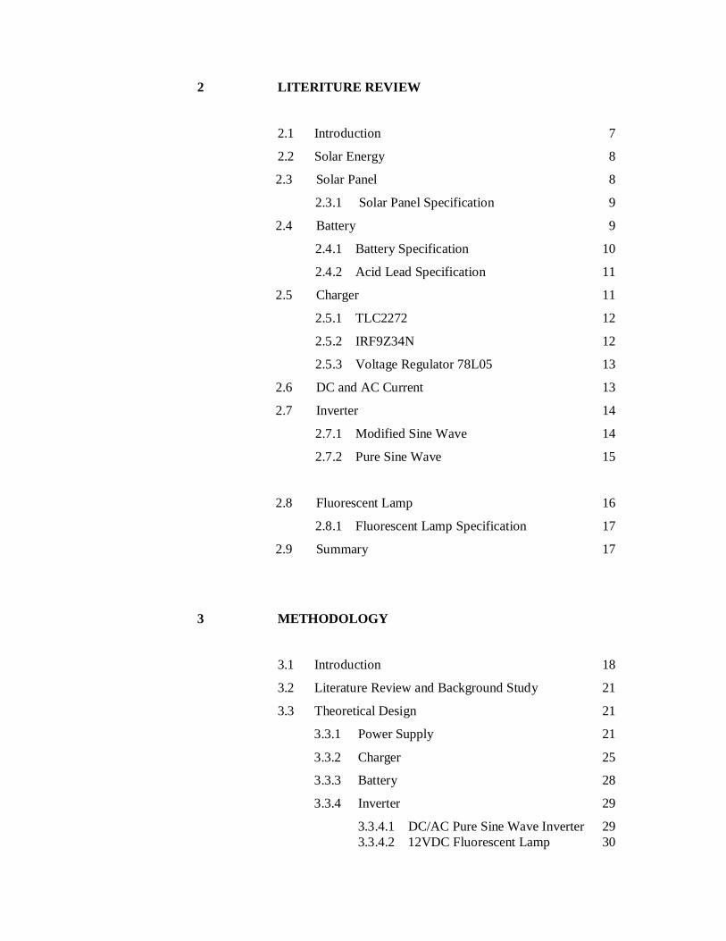
2 LITERITURE REVIEW
2.1 Introduction 7
2.2 Solar Energy 8
2.3 Solar Panel 8
2.3.1 Solar Panel Specification 9
2.4 Battery 9
2.4.1 Battery Specification 10
2.4.2 Acid Lead Specification 11
2.5 Charger 11
2.5.1 TLC2272 12
2.5.2 IRF9Z34N 12
2.5.3 Voltage Regulator 78L05 13
2.6 DC and AC Current 13
2.7 Inverter 14
2.7.1 Modified Sine Wave 14
2.7.2 Pure Sine Wave 15
2.8 Fluorescent Lamp 16
2.8.1 Fluorescent Lamp Specification 17
2.9 Summary 17
3 METHODOLOGY
3.1 Introduction 18
3.2 Literature Review and Background Study 21
3.3 Theoretical Design 21
3.3.1 Power Supply 21
3.3.2 Charger 25
3.3.3 Battery 28
3.3.4 Inverter 29
3.3.4.1 DC/AC Pure Sine Wave Inverter 29 3.3.4.2 12VDC Fluorescent Lamp 30
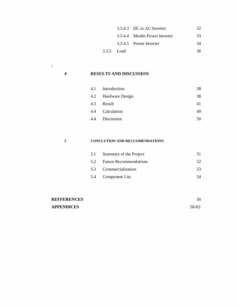
3.3.4.3 DC to AC Inverter 32
3.3.4.4 Mosfet Power Inverter 33
3.3.4.5 Power Inverter 34
3.3.5 Load 36
\
4 RESULTS AND DISCUSSION
4.1 Introduction 38
4.2 Hardware Design 38
4.3 Result 41
4.4 Calculation 49
4.4 Discussion 50
5 CONCLUTION AND RECCOMENDATIONS
5.1 Summary of the Project 51
5.2 Future Recommendations 52
5.3 Commercialization 53
5.4 Component List 54
REFFERENCES 56
APPENDICES 58-83
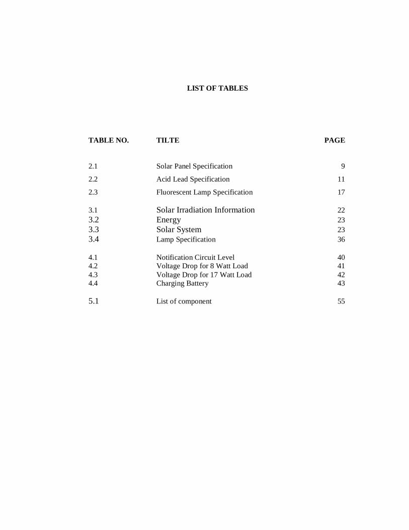
LIST OF TABLES
TABLE NO. TILTE PAGE
2.1 Solar Panel Specification 9
2.2 Acid Lead Specification 11
2.3 Fluorescent Lamp Specification 17 3.1 Solar Irradiation Information 22 3.2 Energy 23 3.3 Solar System 23 3.4 Lamp Specification 36 4.1 Notification Circuit Level 40 4.2 Voltage Drop for 8 Watt Load 41 4.3 Voltage Drop for 17 Watt Load 42 4.4 Charging Battery 43 5.1 List of component 55

LIST OF FIGURES
FIGURE NO. TITLE PAGE
1.1 Basic Controller 3
1.2 Basic DC/AC 3
1.3 Filtering Diagram 3
2.1 Battery 10
2.2 TLC2272 12
2.3 IRF9Z34N 12
2.4 Voltage Regulator 78L05 13
2.5 Modified Wave 15
3.1 Block Diagram of The System 19
3.2 Flow Chart of the Project 19
3.3 Connection Solar Panel to Charger 22
3.4 Basic Connection of Charger 25
3.5 Charger Circuit 27
3.6 Basic Connection Pure Sine Wave Inverter 30
3.7 Time Duration Wave 31
3.8 Circuit Diagram for 12VDC Fluorescent Lamp 31
3.9 Circuit diagram for DC to AC Inverter 32
3.10 Circuit Diagram for Power Mosfet Inverter 33
3.11 Circuit Diagram for Power Inverter 34
3.12 Inverter Circuit 35
3.13 Actual Load Used 36
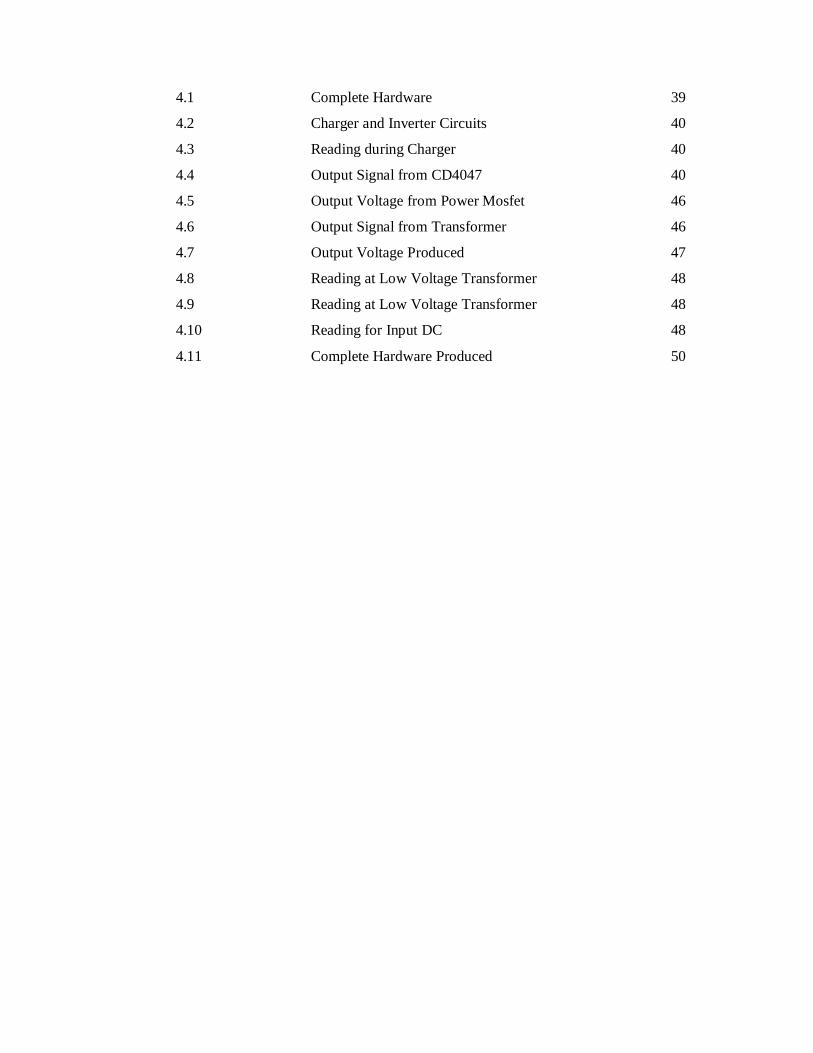
4.1 Complete Hardware 39
4.2 Charger and Inverter Circuits 40
4.3 Reading during Charger 40
4.4 Output Signal from CD4047 40
4.5 Output Voltage from Power Mosfet 46
4.6 Output Signal from Transformer 46
4.7 Output Voltage Produced 47
4.8 Reading at Low Voltage Transformer 48
4.9 Reading at Low Voltage Transformer 48
4.10 Reading for Input DC 48
4.11 Complete Hardware Produced 50
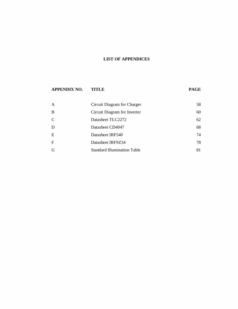
LIST OF APPENDICES
APPENDIX NO. TITLE PAGE
A Circuit Diagram for Charger 58
B Circuit Diagram for Inverter 60
C Datasheet TLC2272 62
D Datasheet CD4047 68
E Datasheet IRF540 74
F Datasheet IRF9Z34 78
G Standard Illumination Table 81
CHAPTER 1
INTRODUCTION
1.1 Overview
Solar panel described two types of devices that collect energy from the sun. It
is solar photovoltaic modules and solar thermal collector. Solar photovoltaic modules
are use solar cells to convert light from sun into electricity. Solar cells are common
examples in this category of electricity generation. An electric power can be
converting from one form to another by using electronic devices. The function of the
electronic circuit by using semiconductor devices is to switching and modifying or
controlling a voltage. It will convert electrical energy from one form to another form.
1.2 Background
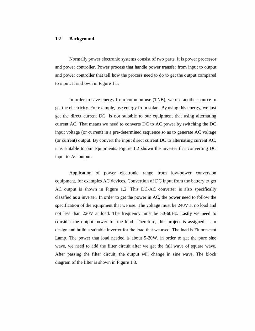
Normally power electronic systems consist of two parts. It is power processor
and power controller. Power process that handle power transfer from input to output
and power controller that tell how the process need to do to get the output compared
to input. It is shown in Figure 1.1.
In order to save energy from common use (TNB), we use another source to
get the electricity. For example, use energy from solar. By using this energy, we just
get the direct current DC. Is not suitable to our equipment that using alternating
current AC. That means we need to converts DC to AC power by switching the DC
input voltage (or current) in a pre-determined sequence so as to generate AC voltage
(or current) output. By convert the input direct current DC to alternating current AC,
it is suitable to our equipments. Figure 1.2 shown the inverter that converting DC
input to AC output.
Application of power electronic range from low-power conversion
equipment, for examples AC devices. Convertion of DC input from the battery to get
AC output is shown in Figure 1.2. This DC-AC converter is also specifically
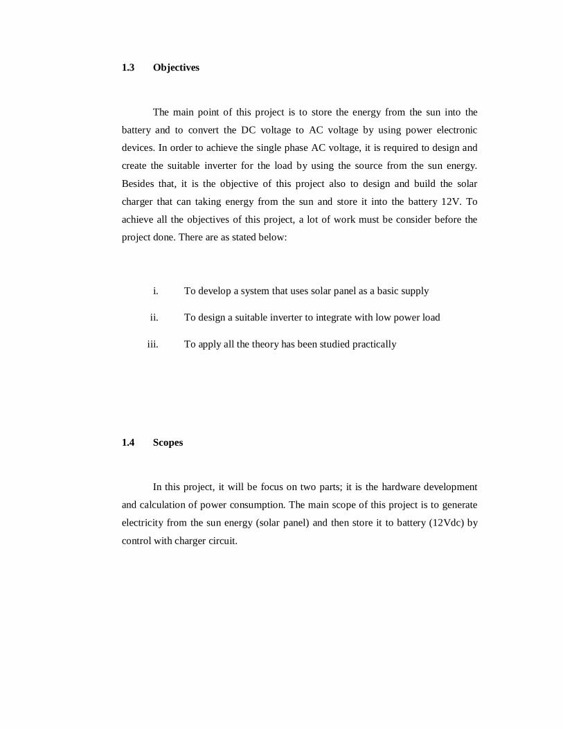
classfied as a inverter. In order to get the power in AC, the power need to follow the
specification of the equipment that we use. The voltage must be 240V at no load and
not less than 220V at load. The frequency must be 50-60Hz. Lastly we need to
consider the output power for the load. Therefore, this project is assigned as to
design and build a suitable inverter for the load that we used. The load is Fluorescent
Lamp. The power that load needed is about 5-20W. in order to get the pure sine
wave, we need to add the filter circuit after we get the full wave of square wave.
After passing the filter circuit, the output will change in sine wave. The block
diagram of the filter is shown in Figure 1.3.
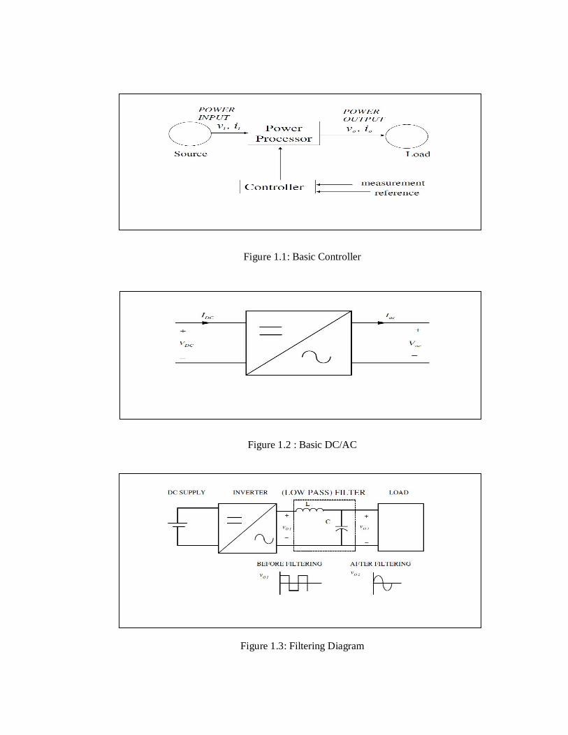
Figure 1.1: Basic Controller
Figure 1.2 : Basic DC/AC
Figure 1.3: Filtering Diagram
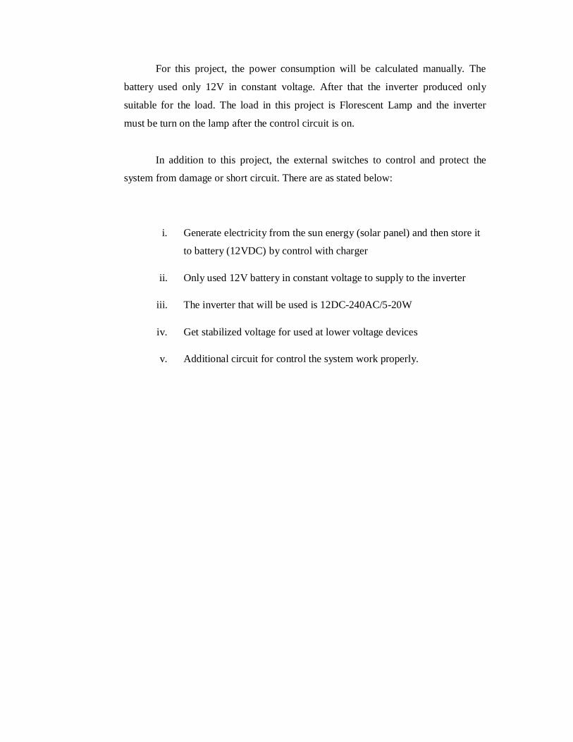
1.3 Objectives
The main point of this project is to store the energy from the sun into the
battery and to convert the DC voltage to AC voltage by using power electronic
devices. In order to achieve the single phase AC voltage, it is required to design and
create the suitable inverter for the load by using the source from the sun energy.
Besides that, it is the objective of this project also to design and build the solar
charger that can taking energy from the sun and store it into the battery 12V. To
achieve all the objectives of this project, a lot of work must be consider before the
project done. There are as stated below:
i. To develop a system that uses solar panel as a basic supply
ii. To design a suitable inverter to integrate with low power load
iii. To apply all the theory has been studied practically
1.4 Scopes
In this project, it will be focus on two parts; it is the hardware development
and calculation of power consumption. The main scope of this project is to generate
electricity from the sun energy (solar panel) and then store it to battery (12Vdc) by
control with charger circuit.
For this project, the power consumption will be calculated manually. The
battery used only 12V in constant voltage. After that the inverter produced only
suitable for the load. The load in this project is Florescent Lamp and the inverter
must be turn on the lamp after the control circuit is on.
In addition to this project, the external switches to control and protect the
system from damage or short circuit. There are as stated below:
i. Generate electricity from the sun energy (solar panel) and then store it
to battery (12VDC) by control with charger
ii. Only used 12V battery in constant voltage to supply to the inverter
iii. The inverter that will be used is 12DC-240AC/5-20W
iv. Get stabilized voltage for used at lower voltage devices
v. Additional circuit for control the system work properly.
1.5 Problem Statement
Today, the system that using the solar panel as a source for the fluorescent
lamp is very hard to found, especially at the bus stop. In easy word is no installation
of solar fluorescent lamp at bus stop in Malaysia. Today, technology is very
important and very useful to us. So we need to find way to improve ourselves. For
example, generate the electricity using energy from the sun light. That we call is the
solar photovoltaic modules. Because of that, we not hope electricity from TNB only
but we can make it ourselves.
That’s why this system is designed. The problem here is we cannot produces
constant supply for the load, so the charger needs to be design to store the energy to
the battery. The output will stable when supply from battery is constant. Normally,
the inverter is very hard to design because the input in DC and the output is AC, it is
easy to burn. So the component must be suitable for higher temperature and higher
efficiency. Nowadays, a lot of product used for DC load only, but this system is
designed for load in AC
1.6 Thesis Organization
There are all five chapters being structure in this thesis and every chapter will
elaborate in details about this project. Chapter 2 is about the literature review. The
data and the theory will be taking from this part before move to the next chapter.
Chapter 3 is all about the methodology. This chapter will be discussing about the
flow or the method that applied into this project. All detail explanation about the
project in this chapter. Chapter 4 is displaying the result and discussing about the
project after all the circuit finish. Chapter 5 in overall will discuss about the
conclusion and summary of the project. This chapter also states the problem and
recommendation for the project.
CHAPTER 2
LITERATURE REVIEW
2.1 Introduction
In order to perform this project, literature review has been made from various
sources like journals, books, articles and others. All of this will be references for this
project and also make idea to produce suitable circuit or inverter for the charger and
also the inverter. A review of the article was performed to identify studies that
relevant to the topic. A combination of the following keywords was used to identify
relevant material. The Solar Fluorescent Lamp concept is integrated the solar
charger, battery, inverter and the sensor to switch ON the fluorescent lamp.
2.2 Solar Energy
A solar energy and electric lighting system wherein when the solar energy is
available as in the day-time, it is utilized for lighting through conventional electric
lamps, but when no solar energy is available the lamp are turned on [2]. Using the
light sensor to detect weather no solar energy or not. The solar power source is
suitable for powering outdoor advertising signs. Generally, the solar power source
has application in any environment where the constant power source was desired [3].
It is suitable to apply to bus stop.
2.3 Solar Panel
Solar panel which is also known as photovoltaic is a device that receives the
energy from the sun and then converts it to electrical energy. Solar panel has several
types according to their size and output. It will produce DC voltage [4]. Its output
which is 17Vdc 5A must be store to a battery. The present invention relates to means
for concentration solar energy on solar cells, optimizing the utilization of solar
energy [5]. Outdoor solar energy lamp with luminescence efficiency relates to lamp,
and more particularly to an outdoor solar energy lamp that uses environmental solar
energy as power source and has luminescence function to prolong lamp lighting [6].
By using the environmental source we get to generate the electricity and give the
supply to the fluorescent lamp.
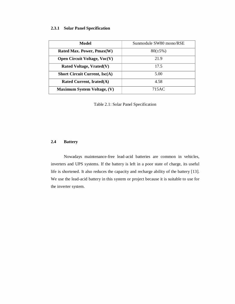
2.3.1 Solar Panel Specification
Model Sunmodule SW80 mono/RSE
Rated Max. Power, Pmax(W) 80(±5%)
Open Circuit Voltage, Voc(V) 21.9
Rated Voltage, Vrated(V) 17.5
Short Circuit Current, Isc(A) 5.00
Rated Current, Irated(A) 4.58
Maximum System Voltage, (V) 715AC
Table 2.1: Solar Panel Specification
2.4 Battery
Nowadays maintenance-free lead-acid batteries are common in vehicles,
inverters and UPS systems. If the battery is left in a poor state of charge, its useful
life is shortened. It also reduces the capacity and recharge ability of the battery [13].
We use the lead-acid battery in this system or project because it is suitable to use for
the inverter system.
2.4.1 Battery Specification
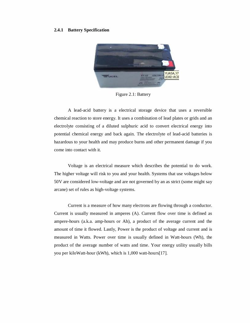
Figure 2.1: Battery
A lead-acid battery is a electrical storage device that uses a reversible
chemical reaction to store energy. It uses a combination of lead plates or grids and an
electrolyte consisting of a diluted sulphuric acid to convert electrical energy into
potential chemical energy and back again. The electrolyte of lead-acid batteries is
hazardous to your health and may produce burns and other permanent damage if you
come into contact with it.
Voltage is an electrical measure which describes the potential to do work.
The higher voltage will risk to you and your health. Systems that use voltages below
50V are considered low-voltage and are not governed by an as strict (some might say
arcane) set of rules as high-voltage systems.
Current is a measure of how many electrons are flowing through a conductor.
Current is usually measured in amperes (A). Current flow over time is defined as
ampere-hours (a.k.a. amp-hours or Ah), a product of the average current and the
amount of time it flowed. Lastly, Power is the product of voltage and current and is
measured in Watts. Power over time is usually defined in Watt-hours (Wh), the
product of the average number of watts and time. Your energy utility usually bills
you per kiloWatt-hour (kWh), which is 1,000 watt-hours[17].
2.4.2 Acid Lead Specification
Model Lead Acid 12V 7Ah
Battery Technology Lead Acid
Energy Storage 7 Ah
Output Voltage 12 V
External Depth/Length/Width 65mm/97.5mm/151mm
Weight 2,65 kg
Table 2.2: Acid Lead Specification
2.5 Charger
The function of the charger circuit is to regulate the power flowing from a
photovoltaic panel into the rechargeable battery. The energy from the sun will be
taking and store it into the battery 12V. The charger will be charge the battery in
certain time in order to make the battery full back. After the battery full, battery can
be use for the inverter circuit. The goal of the circuit design was to make a charge
controller with analog simplicity, high efficiency and reliability. A medium power
solar system can be built with 12V solar panel up to 10 Amp [16].
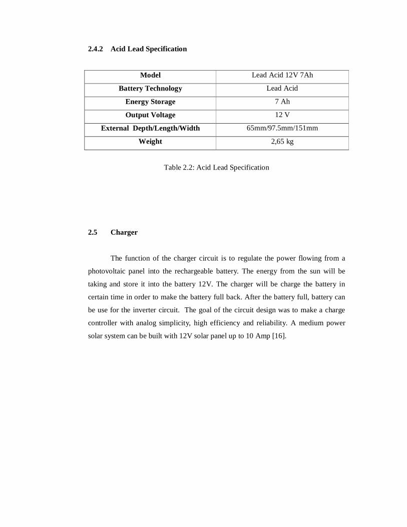
2.5.1 TLC2272
Figure 2.2: TLC2272
A TLC2272 is an operational amplifier IC and it can make a comparator
either the voltage can flow trough it or not. Depend on this type the function in the
charger circuit is to on and activated the transistor to allow the charge into the
battery. This IC also makes the comparator based on the trigger oscillator to make
the solar turn on and off.
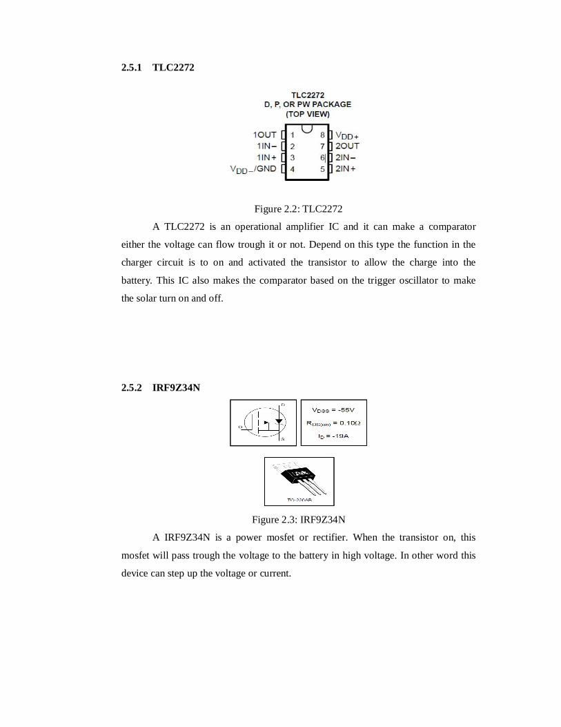
2.5.2 IRF9Z34N
Figure 2.3: IRF9Z34N
A IRF9Z34N is a power mosfet or rectifier. When the transistor on, this
mosfet will pass trough the voltage to the battery in high voltage. In other word this
device can step up the voltage or current.