development of oxy-fuel cfb technologycarboncap-cleantech.com/conf-2013/presentations -...
TRANSCRIPT

September 8 - 9, 2013 Ponferrada Spain 5th Oxyfuel Capacity Building Course
DEVELOPMENT OF OXY-FUEL CFB
TECHNOLOGY FOR POWER GENERATION
Presented by
Timo Eriksson,
Foster Wheeler Energia Oy, Finland
Contents of Presentation
• Background
• Development of Oxy-Fuel CFB technology
• Course of development
• Modeling of oxy-fuel CFB combustion
• Pilot testing activities
• OXY-CFB-300 Compostilla boiler concept
• Summary
"Flexi-Burn" is a trademark of Foster Wheeler AG, registered in the U.S., EU, Finland
WORLD BOOK
Encyclopedia

Development of Oxy-Fuel CFB Technology Background
-200
-100
0
100
200
300
400
500
0 1000 2000 3000 4000 5000 6000 7000
NuclearFuel switch
to gas
CO2 capture
Solar
Geothermal
Efficiency
(end-use and
supply)
Average
Minimum
Maximum
US avoidance
potential
(millions of
tons of CO2)
Source: DOE white paper, 1997
• Avoidance cost:
DOE study from
1997 estimated
CO2 capture cost
at 50 $/ton of
CO2 avoided
• High potential in
avoided volumes
Avoidance cost
$ / t_CO2 (1990)

Development of Oxy-Fuel CFB Technology Roadmap for Development
Release of
oxycombustion
demonstration projects:-Vattenfall /
Schwarze Pumpe, 30 MWth
-Total / Lacq, 50 MWth
Feasibility studies
Process studies
Cost analyses
Market studies
Environm. impact studies
2000
General research & development work
2003 2006 2009 2012 2015
Techno-economic studies
EU/USA 2nd phase demos
EU/USA MW-size demos
Power plant
scale
demonstration
Commercial
size power
plant
Combustion
Emissions
Hydrodynamics
Materials
Technology development
Commissioning
of Oxy-pilots
• Progress in
technology
development
more or less in
schedule
• Large pilots
successful
• But step to large
demos turned out
to be a major
leap • Permitting
• Acceptance
• Economics

Phase II: Construction & operation
2008 2009 2011 2014 2010 2012 2013 2015 2016 2020
VTT
CANMET
CIUDEN
PILOT TESTING
BOILER CONCEPT DEVELOPMENT
SUPPORTING R&D
Development and validation of static and dynamic models
Material studies and testing
FP7 FLEXI BURN CFB
TEKES PROJECTS
FP7 O2GEN
OXY-CFB-300 Compostilla Phase I FID
Commercial cases
Flexi-Burn CFB
OXY-CFB-300
HIGH-O2 CFB
Development of Oxy-Fuel CFB Technology Development Timeline of Flexi-Burn CFB

Development of Oxy-Fuel CFB Technology Challenges
Oxy-CFB in general (1st & 2nd gen.): • Materials in the high CO2 and H2O gas
atmosphere
• Elimination of air in-leakage
• Limestone behavior
• Emissions prediction
• Changes in hydrodynamics and heat
transfer
• Process integration
High-O2 designs (2nd gen.): • Generated heat per volume [kW/m3] and
adiabatic combustion temperature rise.
• Heat balance between hot loop and
HRA area changes
• Heat surface configuration
28
40
60
80
100
0
10
20
30
40
50
60
70
80
90
100
0 500 1000 1500 2000 2500 3000 3500 4000 4500 5000
T adiabatic [°C]
ho
t lo
op
sh
are
of
tota
l h
eat
du
ty o
f b
oil
er
[%]
0
10
20
30
40
50
60
70
80
90
100
O2 s
hare
if inp
ut g
as [%
]
Existing CFB units / designs
O2 CFB designs
O2 share of input gas (O2/CO2)
normal air
combustion
Flexi-Burn CFB
Needs for • Experiments in bench scale and pilot test facilities
• Development and validation of design models
• Long-term demonstration runs

Development of Oxy-Fuel CFB Technology Integrated Experimental and Modeling Work for Scale-Up
nc Xkm
t
mr O2c
c
d
d
COefCO Ykt
Y
d
d
)/1/(1 mCOef kk
nrefv ddTAb )/)(/exp(
Model
analyses
CO combustion
Mixing
Char combustion
Volatile,
moist
ure re
lease
Figure 2 Furnace heat flux
kW/m
2
1D-MODELflue gas
1
n n+1
to stack
Primary airSecondary air
2
n-1
3
n-2
kW/m2
Sub-models
for phenomena 0-D and 1-D stationary /
dynamic models
1-D design model
3-D CFB model
EXPERIMENTAL
SCALES
MODELS AND
DESIGN TOOLS
Boiler scale Pilot scale (small>large) Bench scale
LAGISZA 460 MWe supercritical OTU CFB VTT 0.1 MW CFB pilot test rig VTT 0.3 kW CFB/BFB bench scale test rig
Development of Oxy-Fuel CFB Technology Main Activities
In CCS, Foster Wheeler is mainly focusing on oxy-fuel combustion, having been
developing it since 2003:
• Knowledge and design tool development
• Test activities starting from bench scale
• Conceptual, feasibility and FEED studies (boiler design)
Pilot test activities at larger scale facilities
• ~0.1 MWt (VTT) → ~1 MWt (Canmet 2009-2010) → 30 MWt (2011-13)
• FW supplied the 30-MWt CFB boiler at the CIUDEN technology development plant.
Experiences in scale-up of CFB boilers up to 460 MWe size and on the other hand
in air / oxy firing demonstration in pilots have been combined Flexi-Burn CFB
boiler concept developed and ready for demonstration.

CFB Boiler Development
In parallel, scale-up of air-fired CFB boilers has continued.
• The world first SC-OTU CFB at PKE’s Lagisza plant in Poland started commercial
operation in 2009.
• FW is supplying 4 x 550 MWe CFB boilers for Samcheok Green Power Project in Korea
(KOSPO), with 258/54 bara, 603/603 °C steam parameters.
• Developed CFB technology further up to 600-800 MWe (for ~ 45 % net efficiency) unit
size

Development of Oxy-Fuel CFB Technology Recent Activities
R&D support - EU FP7 project "FLEXI BURN CFB"
2009 – 2013 • Design tool development toward oxy & air compatibility
(combustion, heat transfer, fluid dynamics, emissions)
• Experiments in small and large scale pilots → scale-up
information
• Performance of materials
• Dynamic simulations
• Concept optimization, etc.
Boiler design - Oxy-CFB-300 Compostilla project 2009
– 2013 • Engineering of Flexi-Burn CFB boiler
• Performance and cost estimates
• Design verification at CIUDEN TDP
• Support of FEED study by ENDESA → plant level estimates
Development of Oxy-Fuel CFB Technology Model Development for Oxycombustion
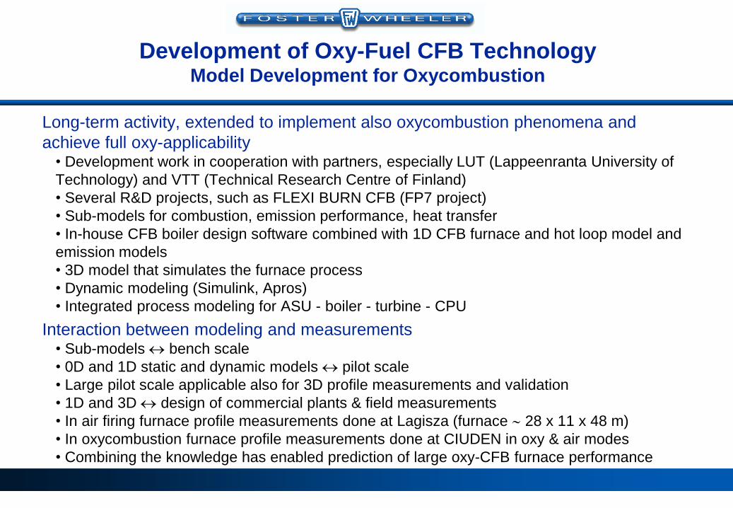
Long-term activity, extended to implement also oxycombustion phenomena and
achieve full oxy-applicability • Development work in cooperation with partners, especially LUT (Lappeenranta University of
Technology) and VTT (Technical Research Centre of Finland)
• Several R&D projects, such as FLEXI BURN CFB (FP7 project)
• Sub-models for combustion, emission performance, heat transfer
• In-house CFB boiler design software combined with 1D CFB furnace and hot loop model and
emission models
• 3D model that simulates the furnace process
• Dynamic modeling (Simulink, Apros)
• Integrated process modeling for ASU - boiler - turbine - CPU
Interaction between modeling and measurements • Sub-models bench scale
• 0D and 1D static and dynamic models pilot scale
• Large pilot scale applicable also for 3D profile measurements and validation
• 1D and 3D design of commercial plants & field measurements
• In air firing furnace profile measurements done at Lagisza (furnace 28 x 11 x 48 m)
• In oxycombustion furnace profile measurements done at CIUDEN in oxy & air modes
• Combining the knowledge has enabled prediction of large oxy-CFB furnace performance

Development of Oxy-Fuel CFB Technology 1D Model Development
• 1D CFB furnace model is one of the core
modules in the FWOY´s boiler design
software.
• 1D furnace model is comprised of several
sub-routines simulating process
phenomena in combustion and CFB hot
loop (including INTREX).
• Emission models
• Oxycombustion features have been
implemented in the model (e.g.oxidant
system)
CFB boiler design
software
• Validation of the 1D CFB furnace model with test data • Measured furnace temperature, pressure (solids density) and oxygen profiles
• Feed material & ash flow rates, chemical composition, physical properties and PSD ash
balance (also fractional balances for different particle sizes)
• Circulating solids: composition, PSD

Development of Oxy-Fuel CFB Technology 3D Model Development
• 3D model simulates the furnace process. • Furnace divided to control volumes
• Boundary conditions include all the different feeds (e.g. fuels, gas feeds) and thermal conditions at walls.
• Separate models for separators and INTREX units
• Developed submodels (e.g. sorbent model) implemented to the 3D model
• Improvements to increase the robustness of the code and the calculation speed
Separator(s)
- separation eff.
- heat transfer
- reactions
Heat transfer
to walls and
internal
surfaces
Fluidization gas
Inlet sources
- sec. gas
- fuel
- limestone
- sand
External heat
exchangers
- heat transfer
- reactions
Flue gas,
fly ash
Exchange of
gas / solids
Solids to
furnace
Gas, solids
Combustion,
gasification &
other reactions
Solids
Bottom ash
Fluidization
gas
Recirculation of flue gas / fly ash
Solids
Gas
• Applied e.g. for studying the number and placement of fuel and oxidant feeds, in-furnace heat exchangers and separators temperature, velocity and gas composition profiles, heat fluxes

Development of Oxy-Fuel CFB Technology Dynamic Model Development
• Dynamic model / module development for FLEXI BURN CFB boiler system,
building on existing air-fired models validated for large CFB units (e.g. Lagisza
460 MWe SC-OUT CFB)
• Sub-models: furnace, water/steam path, flue gas path, combustion gas
preparation (mixing recirculated flue gas and oxygen)
• The model excludes the ASU, CPU and the BOP (balance of plant) systems;
integrated plant modeled separately (VTT).
• The model is capable to perform between 40% and 100% BMCR.
• The main control loops, unit master control, boiler control and steam temperature
control loops are applied.
• The 1-D dynamic hot-loop model (Simulink) is integrated into the Apros boiler
simulation model as dll module.
• Both steady-state and dynamic performances of the 300 MWe Flexi-Burn CFB
boiler have been investigated in Apros simulation environment.

Development of Oxy-Fuel CFB Technology VTT Tests
Experimental oxy-fuel combustion studies with
small scale fluidized bed combustors at VTT in
Jyväskylä since 2004
Small pilot scale (30-100 kW) circulating
fluidized bed (CFB) reactor • Height of riser 8 m, ID 0.17 m
• Combustion with O2 + recycled flue gas
• Combustion with bottled gases
• Air firing
• Several fuels tested, e.g. S.A. and Polish bituminous coals, Spanish and Russian anthracites, petcoke
• Steady-state and dynamic tests
Bench scale BFB/CFB reactor (< 1 kW) suitable
for studies of oxygen combustion phenomena
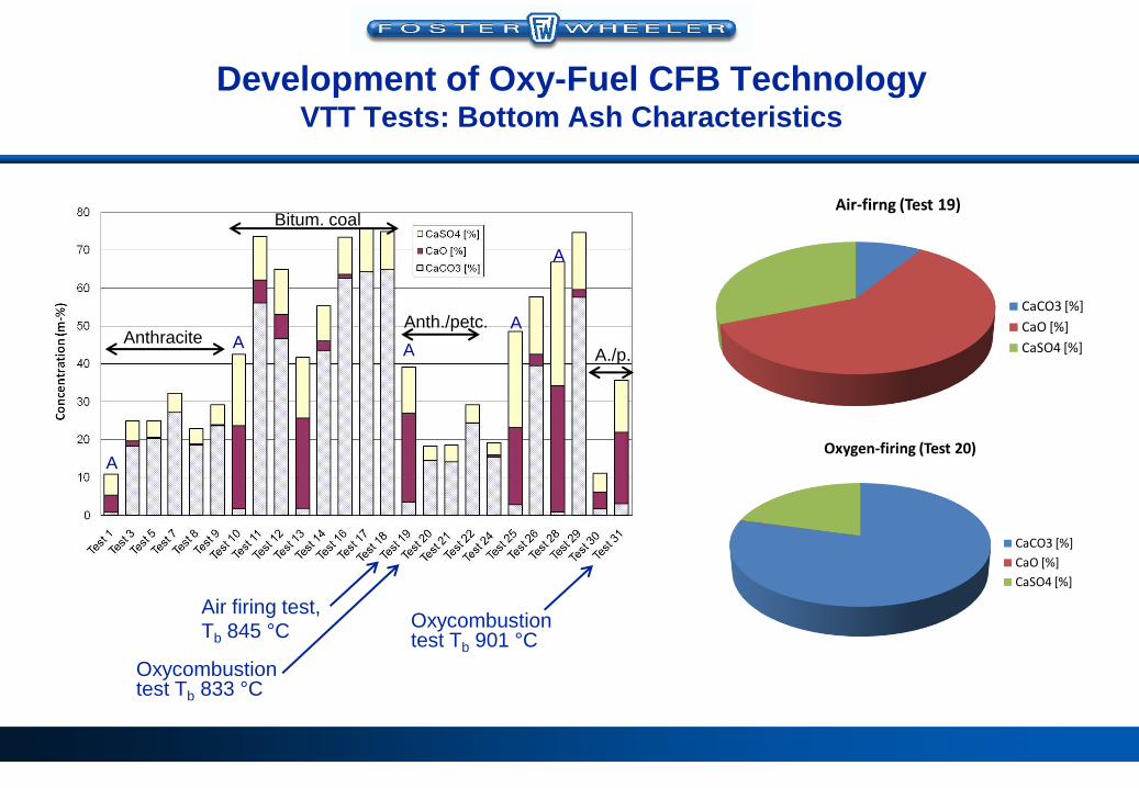
Development of Oxy-Fuel CFB Technology VTT Tests: Bottom Ash Characteristics
Air-firng (Test 19)
CaCO3 [%]
CaO [%]
CaSO4 [%]
Oxygen-firing (Test 20)
CaCO3 [%]
CaO [%]
CaSO4 [%]
Air firing test, Tb 845 °C
Oxycombustion test Tb 833 °C
A
A
Anthracite A
Bitum. coal
Anth./petc. A
A
A./p.
Oxycombustion test Tb 901 °C

Flexi-Burn CFB Boiler Development CANMET Tests
Design parameters: • Furnace: Ø 16” x 21.6 ft
• Refractory lined furnace, cyclone and return loop
• Four bayonet cooling tubes for furnace temperature control (adjustable on-line)
• Fuel and limestone feeding systems
• Recycle gas cooler ( dry RFG), fan and oxygen mixer for oxidant preparation
• Oxygen storage tank with a vaporizer and instrumentation
• Analyzers for continuous measurement of CO2, CO, O2, SO2, and NOx
• Data acquisition system
• Tests run with Spanish anthracite and lignite,
petcoke, S.A. bituminous coal and blends in
2010 • Totally 15 test weeks, 88 tests (35 air + 53 oxy)
• Focus on differences in combustion, emissions etc. between oxy and air combustion

Flexi-Burn CFB Boiler Development CANMET Tests
• Combustion, firing rate,
emissions-related issues,
mixing, heat transfer, fouling
and corrosion studied
• Steady combustion process in
both air and oxy modes
• The most important conclusion
was that no major issues
contradicting previous
assumptions and
understanding were identified
during the tests.

• Commissioning tests fall 2011 – spring 2012
• FLEXI BURN CFB (FP7) tests in July – September 2012
• EEPR tests (CPU integration) October – December
2012
• Altogether > 2000 hours of oxycombustion tests with
anthracite, petcoke, sub-bituminous and bituminous
coals, wood pellets or various blends
• So far all in so-called 1st generation oxy-CFB (Flexi-
Burn) • < 30 % O2 in oxidants
• Max. fuel input 18 MW
• Tests in so-called 2nd generation oxy-CFB mode with
higher oxidant O2 planned for 2013 - 2014
Flexi-Burn CFB Boiler Development CIUDEN TDP Tests

• Boiler operation and performance generally not outstandingly different (oxy vs. air)
• Furnace control with oxidant O2 demonstrated; similar oxidants used as in
planned OXY-CFB-300 boiler concept
• Optimal furnace operating parameters (e.g. temp.) with the design fuel determined
• Combustion efficiency similar in both modes
• Sulfur capture in oxycombustion proved very efficient at high temperatures but
poorer at temperatures below calcination (anthracite/petcoke).
• Existing design tools found valid for prediction of suspension density and heat
transfer in oxy mode
• No clear recarbonization issues encountered, however INTREX conditions not
fully representative (low solids outlet T)
• Correct PSD (crushing) of anthracite is important due to hard ash.
• No fouling in the HRA, sootblowing effective
• Acid dew point issues avoidable through limestone feeding, control of surface
temperatures and elimination of leaks (important also for flue gas CO2). Test
duration was obviously too short to experience boiler tube degradation.
OXY-CFB-300 boiler design verification
Flexi-Burn CFB Boiler Development CIUDEN TDP Tests: Significant Results

OXY-CFB Boiler Design Scale-Up from Pilot to Commercial Size
Parameter Unit CIUDENOXY-CFB-300
Flexi-Burn
CFB
Lagisza
460 MWe, gr.
700-MWe
High-O2 CFB
Furnace dimensions
Height m 20 37 48 52
Width m 2.9 28 27.6 29.7
Depth m 1.7 7 10.6 9.5
Number of separators - 1 4 8 6
Thermal power(1
Oxy mode (max.) MW 30 708 -- 1497
Air mode MW 14.5 647 966 --
Steam parameters(2
SH steam flow t/h 47.5 845 1300 1919
SH steam temperature °C 250(3
600 560 600
SH steam pressure bar 30 279 275 257
RH steam flow t/h -- 745 1101 1591
RH steam temperature °C -- 601 580 610
RH steam pressure bar -- 56.5 50.3 55
Feedwater temperature °C 170 290 290 300
Notes: 1) At CIUDEN fuel input; in others heat to steam
2) Steam parameters in Lagisza at turbine inlet
3) After spraying
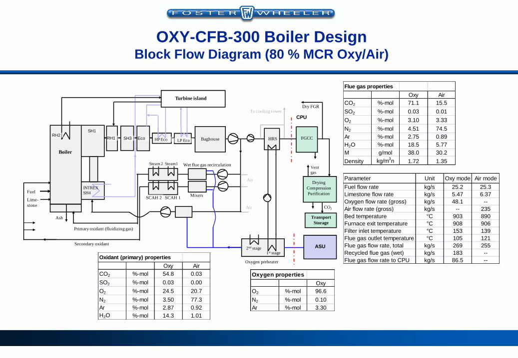
OXY-CFB-300 Boiler Design Block Flow Diagram (80 % MCR Oxy/Air)
Boiler
Baghouse
INTREX
SH4
Wet flue gas recirculation
Oxygen preheater
HRS
Air
ASU
Fuel
Lime-
stone
Secondary oxidant
Primary oxidant (fluidizing gas)
Drying
Compression
Purification
CO2
Vent
gas
Transport
Storage
FGCC
SCAH 1Mixers
CPU
Turbine island
SCAH 2
Steam 2 Steam1
To cooling tower
1st stage2nd stage
HP EcoRH1 EcoSH3LP Eco
RH2
Air
Dry FGR
SH1
Ash
Flue gas properties
Oxy Air
CO2 %-mol 71.1 15.5
SO2 %-mol 0.03 0.01
O2 %-mol 3.10 3.33
N2 %-mol 4.51 74.5
Ar %-mol 2.75 0.89
H2O %-mol 18.5 5.77
M g/mol 38.0 30.2
Density kg/m3n 1.72 1.35
Oxygen properties
Oxy
O2 %-mol 96.6
N2 %-mol 0.10
Ar %-mol 3.30
Oxidant (primary) properties
Oxy Air
CO2 %-mol 54.8 0.03
SO2 %-mol 0.03 0.00
O2 %-mol 24.5 20.7
N2 %-mol 3.50 77.3
Ar %-mol 2.87 0.92
H2O %-mol 14.3 1.01
Parameter Unit Oxy mode Air mode
Fuel flow rate kg/s 25.2 25.3
Limestone flow rate kg/s 5.47 6.37
Oxygen flow rate (gross) kg/s 48.1 --
Air flow rate (gross) kg/s -- 235
Bed temperature °C 903 890
Furnace exit temperature °C 908 906
Filter inlet temperature °C 153 139
Flue gas outlet temperature °C 105 121
Flue gas flow rate, total kg/s 269 255
Recycled flue gas (wet) kg/s 183 --
Flue gas flow rate to CPU kg/s 86.5 --

OXY-CFB-300 Boiler Design Furnace Design
1
2
3
4
5
6
7
1. Furnace (evaporator walls, roof SH I, platen RH II at top)
2. INTREX (SH IV, 4 units)
3. Solids separator (SH I; 4 pcs)
4. Cross-over duct (SH II)
5. Heat recovery area, HRA (walls SH II; tube bundles RH
I, SH III, Economizer)
6. HP Eco and LP Eco
7. Flue gas to filter unit
• Low mass flux BENSON once-through technology
licensed by Siemens AG, Germany
• Furnace with gas tight membrane wall structure
• Heat surface setup shall fulfill the needs of SH and
RH steam in both operating modes, within the load
range.

OXY-CFB-300 Boiler Design Layout
PO mixer
SCAH
Filter
HRC
To CPU
Oxygen
SO
Fan house
Boiler house

Summary
• Foster Wheeler has been developing oxy-fuel CFB technologies for power
generation since 2004.
• Since 2007 the main focus has been in pursued large-scale demonstration in
Spain in cooperation with ENDESA and CIUDEN, in 2010 - 2013 supporting
the OXY-CFB-300 Compostilla project.
• The technology development approach has been similar to previous
development of CFB combustion up to utility size: static and dynamic
modeling, experimental work at different scales (pilot & field tests) and
engineering studies.
• Flexi-Burn CFB application has been succesfully demonstrated for carbon
capture in large pilot scale at the CIUDEN Technology Development Plant.
Experiences gained at the TDP have been used for validation of boiler design
tools and process models, and applied in the final boiler design. Flexi-Burn
CFB is technically ready for demonstration in integrated CCS process.
• Development of capture technology continues in high-oxygen CFB boiler
aiming for increased efficiency and lower cost.

www.oxygenie.com
Thank You!
The work leading to these results has been co-financed under the European Community’s Seventh Framework
Programme (FP7/2007-2013) under grant agreement n° 239188 and the EEPR09-CCS-COMPOSTILLA Project
(European Union's European Energy Programme for Recovery).