development of design work sheets for analysis and design of flexible raft foundations based on...
TRANSCRIPT
DEVELOPMENT OF DESIGN WORK SHEETS FOR ANALYSIS AND DESIGN OF FLEXIBLE RAFT FOUNDATIONS BASED ON BEAMS ON
ELASTIC FOUNDATION
By
MOHD NOR AZZUAN BIN ZA WA WI
FINAL PROJECT REPORT
Submitted to the Civil Engineering Programme in partial fulfillment of the requirements
for the Degree Bachelor of Engineering (Hons)
(Civil Engineering)
Universiti Teknologi PETRONAS Bandar Seri Iskandar
31750 Tronoh Perak Darul Ridzuan
© Copyright 2007 by
Mohd Nor Azzuan Bin Zawawi, 2007

CERTIFICATION OF APPROVAL
DEVELOPMENT OF DESIGN WORK SHEETS FOR ANALYSIS AND DESIGN OF FLEXIBLE RAFT FOUNDATIONS BASED ON BEAMS ON
ELASTIC FOUNDATION
Approved:
by
Mohd Nor Azzuan Bin Zawawi
A project dissertation submitted to the Civil Engineering Programme
Universiti Teknologi PETRONAS in partial fulfillment of the requirement for the
Bachelor of Engineering (Hons) (Civil Engineering)
Ck;L·· AsSl>eiateh.ofesSor Dr. Nasir Shafiq Project Supervisor
UNIVERSITI TEKNOLOGI PETRONAS TRONOH, PERAK
June 2007
ii

CERTIFICATION OF ORIGINALITY
This is to certify that I am responsible for the work submitted in this project, that the
original work is my own except as specified in the references and acknowledgements,
and that the original work contained herein have not been undertaken or done by
unspecified sources or persons.
MOHD NOR AZZUAN BIN ZA WA WI
iii
ABSTRACT
Raft foundations are one of the most appropriate foundation systems in order to
prevent the differential settlement particularly when column loads are large and variable.
The behavior of raft foundation is either rigid and/or flexible depending on the
characteristics of the soil at which the foundation rests. For analysis and design of rigid
raft, traditional methods of reinforced concrete design are available in a number of
literatures; however, the analysis of flexible raft is too tedious and quite cumbersome,
which involve very long formula and complex mathematical functions. This study is
mainly focused on the development of excel work sheets for analysis of flexible rafts
based on beams on elastic foundations that may ease out the tedious calculations and
solutions of complex mathematical functions.
iv
ACKNOWLEDGEMENT
I hereby would like to grab this opportunity to express my deepest gratitude and
gratefulness firstly to God, The Almighty for giving me a chance to acquire new
knowledge and with His will, this project was successfully completed. My special thanks
and appreciation to my project supervisor, Associate Professor Dr. Nasir Shafiq for all
the guidance, advice and commitment in assisting me through out this project A
warmness thanks to all panels that involved in my project's evaluation and improvement.
Same goes to my fellow friends for all the help, support and opinion given in completing
this project. Last but not least I would like to thank my beloved parents, brothers and
sister for giving me moral supports and all parties that involved in completing this
project.
v

TABLE OF CONTENTS
CERTIFICATION ............................................................................................................. ii
ABSTRACT ....................................................................................................................... iv
ACKNOWLEDGEMENT .................................................................................................. v
CHAPTER 1: INTRODUCTION ..................................................................................... 1 1.1 Background of Study ........................................................................ 1 1.2 Problem Statement ............................................................................ 3
1.2.1 Problem Identification ........................................................... 3 1.2.2 Significant of Project ............................................................ 4
1.3 Objectives and Scope of Study ......................................................... 5 1.3.1 The Relevancy of the Project. ............................................... 5 1.3.2 Feasibility of the Project within the Scope and Time Frame 5
CHAPTER 2: LITERATURE REVIEW AND THEORY ............................................... 8 2.1 Mat Foundation (Shallow foundation) .............................................. 8 2.2 Designing Mat Foundation ................................................................ 9 2.3 Rigid and flexible Raft Foundation ................................................. I 0
2.3.1 Rigid Raft Foundation ......................................................... 10 2.3.2 Flexible Raft Foundation .................................................... 11
2.4 Supporting Information (Relevant previous research journals) ...... 11
CHAPTER 3 : METHODOLOGY I PROJECT WORK ................................................. 14 3.1 Project identification ....................................................................... l4
3 .1.1 Project Planning .................................................................. 14 3.12 Literature Study ................................................................... 15 3.1.3 Computer Program Development and Software Usage ...... 16 3.1.4 Manual Calculation ............................................................. 17 3.1.5 Report .................................................................................. l7 3.1.6 Presentation ......................................................................... l8
3.2 Tools I Equipment Used .................................................................. l8
CHAPTER 4 : RESULT AND DISCUSSION ................................................... 19 4. I Findings and Discussion ................................................................. 19
4.1.1 Modulus of Subrade Reaction, ks ....................................... 19 4.12 Other Related Parameters .................................................... 23
4 .1.2. I ks for Centre and Corner ...................................... 23 4.1.2.2 ks Weighting ........................................................ 24 4.1.2.3 ks based on Safety Factor ..................................... 25 4.1.2.4 ks Average ............................................................ 26 4.1.2.5 ks Maximum ......................................................... 26
4.1.3 Moment, Shear and Deflection ........................................... 27
vi
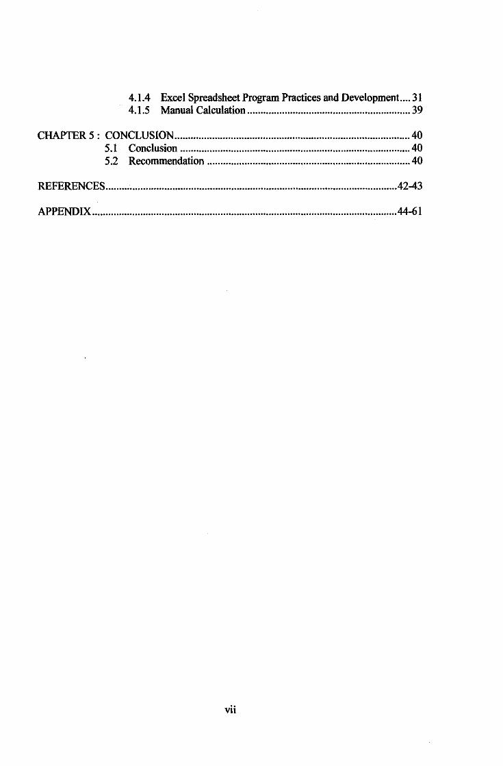
4.1.4 Excel Spreadsheet Program Practices and Development .... 31 4.1.5 Manual Calculation ............................................................. 39
CHAPTER 5 : CONCLUSION ........................................................................................ 40 5.1 Conclusion ...................................................................................... 40 5.2 Recommendation ............................................................................ 40
REFERENCES ............................................................................................................ .42-43
APPENDIX .................................................................................................................. 44-61
vii
LIST OF FIGURES
FIGURE 2.l.la
FIGURE 2.3.la
FIGURE 2.3.2a
FIGURE 4.l.la
FIGURE 4.l.lb
FIGURE 4.l.l c
FIGURE 4.l.ld
FIGURE 4.1.2.la
FIGURE 4.1.3a
FIGURE 4.1.3b
FIGURE 4.1.3c
FIGURE 4.1.4a
FIGURE 4.1.4b
FIGURE 4.1.4c
FIGURE 4.1.4d
FIGURE 4.1.4e
FIGURE 4.1.4f
LIST OF TABLES
Common types of mat foundations.
Rigid Raft Foundation
Flexible Raft Foundation
Modulus ofSubgrade Reaction, ks (1)
Modulus of Subgrade Reaction, ks (2)
Modulus ofSubgrade Reaction, ks (3)
Modulus ofSubgrade Reaction, ks (4)
Fox Chart for IF determination
Modulus ofSubgrade Reaction, ks with effect of Base, B
Finite Length Beam on Elastic Foundation
Infinite Length Beam on an Elastic Foundation with Mid or Center
Loading
Design Work Sheet of Allowable Bearing pressure, q. } First Draft
Design Work Sheet of Modulus ofSubgrade Reaction, k,
Design Work Sheet of Moment, Shear and Deflection
Design Work Sheet of Allowable Bearing pressure, q. } Final Draft Design Work Sheet of Modulus ofSubgrade Reaction, k,
Design Work Sheet of Moment, Shear and Deflection
TABLE 4.1.2.4a Established Range of Modulus ofSubgrade Reaction, ks TABLE 4.1.5a Comparison of Spreadsheet and Manual Calculation Results
viii
CHAPTER!
INTRODUCTION
1.1. Background of study
Every single one of engineered construction resting on the earth must be carried
by some kind of interfacing element called a foundation. The foundation (also called as
substructure) is the part of an engineered system that transmits to, and into, the
underlying soil or rock the loads supported by the foundation and it's self-weight. The
term superstructure is commonly used to describe the engineered part of the system
bringing load to the foundation. This term has particular significance for building and
bridge; however, foundations also may carry only machinery, support industrial
equipment (pipes, towers, and tanks), act as sign bases, and the like. For these reasons it
is better to describe a foundation as the part of the engineered system that interfaces the
load-carrying components to the ground.
Even the ancient builders knew that the most carefully designed structures can fail
if they are not supported by suitable foundations. The Tower ofPisa in Italy (perhaps the
world's most successful foundation "failure") reminds people of this truth. Although
builders have acknowledged the importance of firm foundations for countless
generations, and the history of foundation engineering as people know today did not
begin to develop until the late nineteenth century. Early foundation designs were based
solely on precedent, intuition, and common sense. In the course of trial-and-error,
builders developed rules for sizing and constructing foundations. For example, load
bearing masonry walls built on compact gravel in New York City during the nineteenth
century were supported on spread footings that had a width 1.5 times that of the wall.
Those built on sand or stiff clay were three times the width of the wall (Powell, 1884).
1

As structures prolonged to become larger and heavier, engineers continued to gain
knowledge more about foundation design and construction. Instead of simply developing
new empirical rules, they began to investigate the behavior of foundations and develop
more rational methods of design, hence establishing the discipline of foundation
engineering. The development of geotechnical engineering, which began in earnest
during the 1920s, offered a better theoretical base for foundation engineering. It also
provided advanced methods of exploring and testing soil and rock. These developments
carried on throughout the twentieth century. Many new methods of foundation
construction also have been developed, making it possible to build foundations at sites
where construction had previously been impossible or impractical.
Today, people's knowledge of foundation design and construction is much better
than it was one hundred years ago. It is now possible to build reliable, cost-effective, high
capacity foundations for all types of modern structures. Foundation can be divided into
two broad categories; shallow foundations and deep foundations. Shallow foundations
transmit the structural loads to the near-surface soils, consists of spread footings (square,
circular, rectangular), combined footings, continuous footings or mats/raft foundation.
Deep foundations transmit some or all the loads to deeper soils, e.g piles, anchors, auger
cast piles, drilled shafts, drilled caissons, pressure-injected footing or manderel-driven
thin shells filled with concrete.
In this project, the research focused on the raft or mat foundation which is in the
shallow foundations classification. Shallow foundation usually is the more economical
option. As a general rule, consider deep foundations only when shallow foundations do
not give satisfactory design. A raft foundation is a large concrete slab used to interface
one colunm, or more than one colunm in several lines, with the base soil. It may en
compass the entire foundation area or only a portion. The foundation's behavior is
governed by two systems based on the soil properties which are rigid or flexible. Both
behaviors were investigated, but this project mainly emphasized on the flexible raft
foundation.
2
1.2 Problem Statement
1.2.1 Problem Identification
The soil properties will influence the type of foundation to be used. In most
difficult soil, construction practitioners usually adopt pile foundation for safety and
comfort of design even though it is reliable to used shallow foundation such raft
foundation. They always refer to piling system since lack of knowledge of raft
foundation. Piles are very expensive compare to shallow foundation like raft. Therefore
the studies and research of this project focusing on the raft foundation behavior to
introduce its usage and applications, enhance and publicize the knowledge for the student
himself and also other people. By having knowledge on this matter, the foundation can be
used and hence, the cost will be reduced.
Advantages of using shallow foundation (Mat foundation);
1- Cost (affordable compared to deep foundation)
2- Construction Procedure (simple and efficient time management)
3- Materials (mostly concrete)
4- Labor (does not need expertise)
Focusing on raft foundation, there are two behaviors regarding this type of
foundation which are rigid and flexible. Both flexible and rigid is the stress distribution
system beneath the foundation that needs to be determined before designing any
foundation. The analysis and design of rigid raft are available in a number of literatures
compare to the flexible raft which is less in the market and involve tedious calculations
and solutions of complex mathematical functions.
In raft foundation design, the rigid approach is simpler than flexible. It assumes
the mat is much more rigid than the underlying soils, which means any distortions in the
mat are too small to significantly impact the distribution of bearing pressure.
Unfortunately, flexible approach is more difficult to implement because they require
consideration of soil-structure interaction and because the bearing pressure is not as
simple. For that reason, this project mainly focused on the flexible raft foundation.
3

1.2.2 Significant ofthe Project
One of approach in designing the raft foundation which is being focused in this
project is a "flexible system". This approach will be much influenced by the soil
properties and governed by the soil parameters which are the modulus of subgrade
reaction, k,.. k,. is the conceptual relationship between soil pressure and deflection of
foundation members. This k,. is very important in the determination of moment, shear and
deflection of the raft foundation which later will be used reinforced concrete design.
These three elements are the most significant matters to take care of before proceed for
any reinforced concrete design. In order to obtain the k., moment, shear and deflection,
there will be lots of other parameters to be verified first. All of these involved tedious
calculations and solutions of complex and long mathematical functions.
This project focused on the development of design work sheets to ease the
determination of all parameters discussed above in flexible raft foundation analysis and
design. The flexible raft foundation analysis and design are based on the beams on elastic
foundation. When flexural rigidity of the footing is taken into account, a solution can be
used that is based on some form of a beam on an elastic foundation. With aids of these
design work sheets, they will ease out the tedious calculations and solutions of complex
mathematical functions and compute the result of calculations with only few input data
instead of long manual calculations, thus saving time. They also will produce the precise
value of the analysis and avoid mistakes in calculations. The reinforced concrete design
can be proceed faster whenever the moment, shear and deflection are obtained. This is the
main target for this project.
Each of the tedious and long formulae involved in the analysis were entered into
the excel spreadsheet to create a program or software. When foundation design is made,
the user can enter the related design and soil properties data into these work sheets. With
just a few input data, the user can get lots of important parameters needed for the RC
design like which have been discussed before. For the analysis matter, many of the data
and parameters already prepared and calculated in the work sheets. Only few input data
needed from the designer. There are also several conditions need to be fulfilled in order
4
to proceed with the calculations, but all of these already encountered by the design work
sheets with the practiced of if-else function. Without thinking too much, the user can
enter the data according to the simple instructions given.
1.3 Objective and Scope of Study
1.3.1 The Relevancy of the Project
The objectives of this project are:-
1) To investigate behavior (rigid and flexible) of raft foundation based on soil
properties
* Both behaviors were investigated to know each characteristic, but detail
investigations more focusing on flexible behavior and analysis
2) To develop Excel Work Sheets for analysis of flexible rafts based on beams
on elastic foundations to:-
- Ease out tedious calculations and solutions of complex mathematical
functions
- Compute the result of calculations with only few input data instead of
long manual calculations, thus saving time
- Produce the precise value of the analysis and avoid mistakes in
calculations
1.3.2 Feasibility of the Project within the Scope and Time Frame
The feasibility study of the project within the scope is to get the best way how to
manage the task given and gather the required information about the raft foundation
(rigid/flexible) for the behavior investigation. This is the challenges in order to attain all
the needed information from any source or references as well as the expertise in the tools
or programs involved.
The project scopes mainly focused on the development of excel work sheets for
analysis of flexible rafts based on beams on elastic foundations. Along with this, the
5
investigation of both behaviors of raft foundation (rigid and flexible) based on soil
properties was carried out but precisely focused more on the flexible raft foundation
behavior. This is because of the research focusing on the development of flexible raft
foundation design worksheets for analysis. The research also emphasized on the concept
in determining the modulus of subgrade reaction and moment, shear and deflection of the
foundation. These three elements are the important matters for the reinforced concrete
design. In order to obtain the modulus of subgrade reaction and moment, shear and
deflection, there are several other parameters need to be determined first. Therefore this
matter will be included in the project scope. The soil properties/data and design
parameters were assumed in the analysis. The analysis of these design work sheets is
based on a single concentrated load.
Last semester, for the Final Year Project I, the scope focused more on the research
for the project. The research and studies were conducted on basic of foundation, shallow
foundation (raft foundation), rigid and flexible behavior, modulus of subgrade reaction,
moment, shear and deflection of foundation and other related parameters that involved in
the analysis. In addition to that, excel program usage enhancement and practices have
been done through out the semester. These are to develop skills in using the program and
also adept to the application of if -else and other complicated functions. The relevant
researches were included in the literature review of what theory that have been used and
also the discussion on the findings chapter. The researches from last semester still
continue until this semester because of the author still upgrading his studies on this
project time after time. Additional findings are always adapted. There were few drafts on
the development of the design work sheets done during last semester. The first design
worksheets developed were only consider one type of soil data at any particular area.
This semester for the Final Year Project II, the scope focused on the development
of the design work sheets. The first drafts of the design worksheets from the last semester
were improved throughout this semester. The target are to consider more than one type of
soil to be analyzed because in a logical aspects, there usually exists more than one type of
soil in any particular area being considered for the design. These already been
6
implemented into the design worksheets. The input data slots were re-arranged to ease the
user in entering the input organizely. Throughout this semester, the improvement also
focusing more on to reduce as many as possible the input data so that more time saving
program can be obtained.
The references use for this project includes foundation analysis & design
handbooks, journals of previous research that have been done, websites and etc. The
skills enhancement in the excel program usage was achieved through self-learning and
also with reference to the expertise in this field especially the author's supervisor, A.P.
Dr. Nasir Shafiq. Discussion from time to time with the supervisor detected any
weaknesses and lead to the improvement of the project. All these contributed to the
project completion with success achievement. The project started within the time frame
using all the knowledge and information that have been acquired. The design work sheets
were completed at the end of three quarter period of this semester.
7
CHAPTER2
LITERATURE REVIEW
2.1. Mat foundation (Shallow foundation)
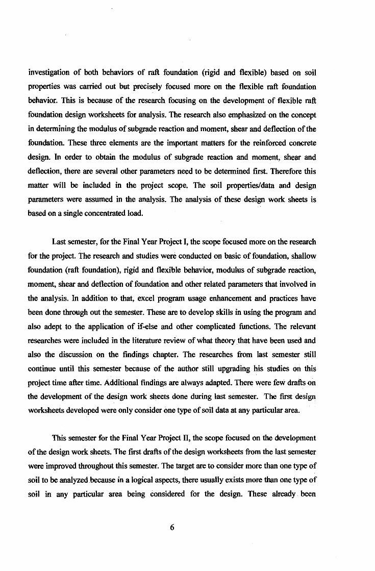
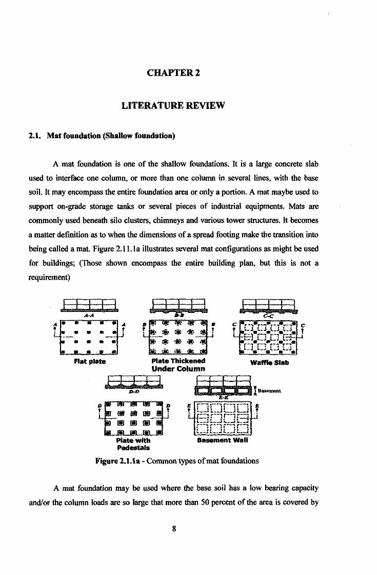
A mat foundation is one of the shallow foundations. It is a large concrete slab
used to interface one column, or more than one column in several Jines, with the base
soil. It may encompass the entire foundation area or only a portion. A mat maybe used to
support on-grade storage tanks or several pieces of industrial equipments. Mats are
commonly used beneath silo clusters, chimneys and various tower structures. It becomes
a matter definition as to when the dimensions of a spread footing make the transition into
being called a mat Figure 2.1 J.la illustrates several mat configurations as might be used
for buildings; (Those shown encompass the entire building plan, but this is not a
requirement)
.. . !
• • • •
a A
•• !
• • • • • • ••
l I I I l
Flat plate Plate Thickened Waffle Slab Under Column
l l I ± l l i i i liB-•
Plate with Pedestals
£-£
Basement Wall
Figure 2.1.1a - Common types of mat foundations
A mat foundation may be used where the base soil has a low bearing capacity
and/or the column loads are so large that more than 50 percent of the area is covered by
8
conventional spread footings. It is common to use mat foundations for deep basements
both to spread the column loads to a more uniform pressure distribution and to provide
the floor slab for the basement. A particular advantage for basement at or below the GWT
is to provide a water barrier. Depending on local costs, and nothing that a mat foundation
requires both positive and negative reinforcing steel, one may find it more economical to
use spread footings. The mat contact stresses will penetrate the ground to a greater depth
or have greater relative intensity at a shallower depth. Both factors tend to increase
settlements unless there is stress compensation from excavated soil so that the net
increase in pressure is controlled.
2.2. Designing Mat foundation
1- Determine the bearing capacity of the foundation
2- Determine the settlement of the foundation
3- Determine the differential settlement
4- Determine the stress distribution beneath the foundation
From Step (4)
a- The mat foundation is assumed to be a Rigid foundation
b- The mat foundation is assumed to be a Flexible Foundation; here use
Beam on Elastic
5- Design the structural components of the mat foundation using the stress distribution
obtained from (4).
For step 4, here the rigid and flexible approaches become the matter of concern
when determining the stress distribution or stress system beneath the mat foundation to
be designed. The rigid and flexible behavior of the mats will be governed by the modulus
of subgrade reaction, K,. The higher value of modulus of subgrade reaction, the more
possibility towards flexible system approach. These parameters will be discussed later in
the discussion on findings chapter.
9
2.3. Rigid and flexible Raft Foundation
Before going further, it's better to know about the fundamental concepts and
differences of raft foundation behavior. In can be divided into two categories: Rigid and
flexible.
2.3.1 Rigid Raft Foundation
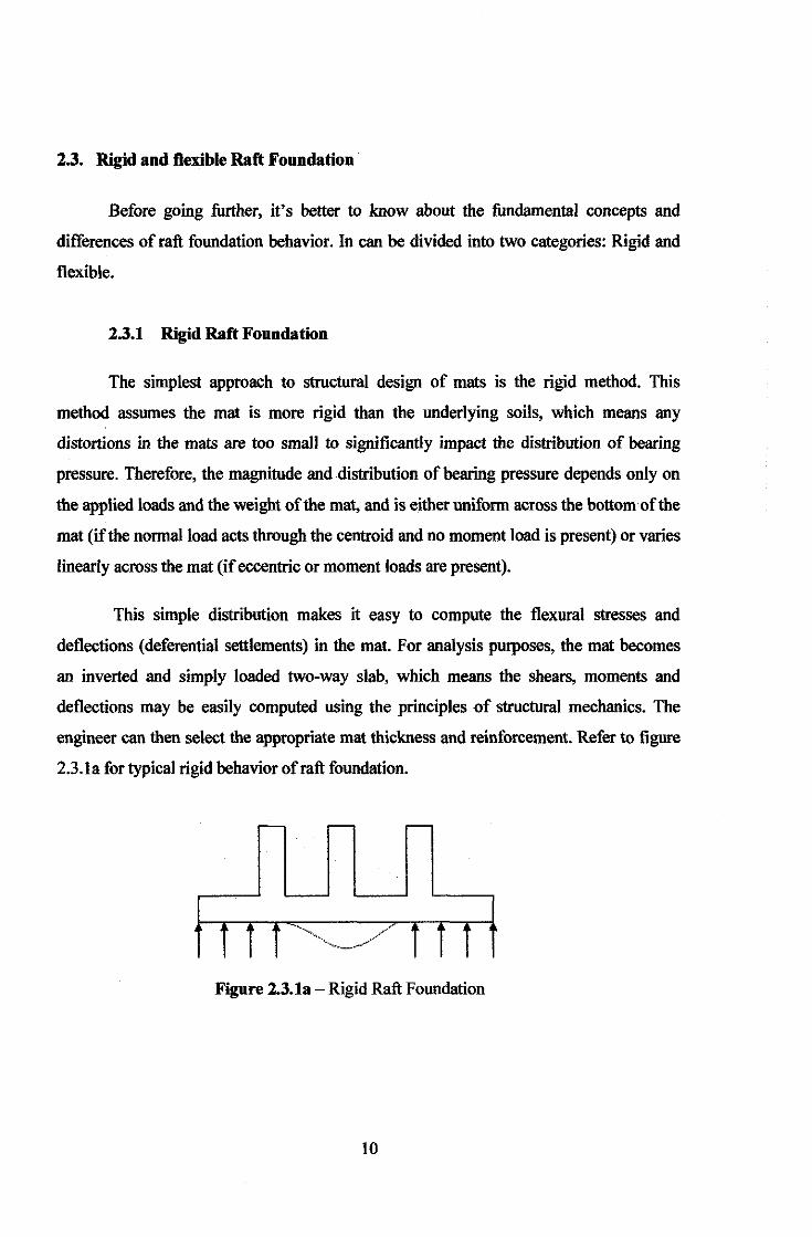
The simplest approach to structural design of mats is the rigid method. This
method assumes the mat is more rigid than the underlying soils, which means any
distortions in the mats are too small to significantly impact the distribution of bearing
pressure. Therefore, the magnitude and distribution of bearing pressure depends only on
the applied loads and the weight of the mat, and is either uniform across the bottom of the
mat (if the normal load acts through the centroid and no moment load is present) or varies
linearly across the mat (if eccentric or moment loads are present).
This simple distribution makes it easy to compute the flexural stresses and
deflections (deferential settlements) in the mat. For analysis purposes, the mat becomes
an inverted and simply loaded two-way slab, which means the shears, moments and
deflections may be easily computed using the principles of structural mechanics. The
engineer can then select the appropriate mat thickness and reinforcement. Refer to figure
2.3.la for typical rigid behavior of raft foundation.
Figure 2.3.1a -Rigid Raft Foundation
10
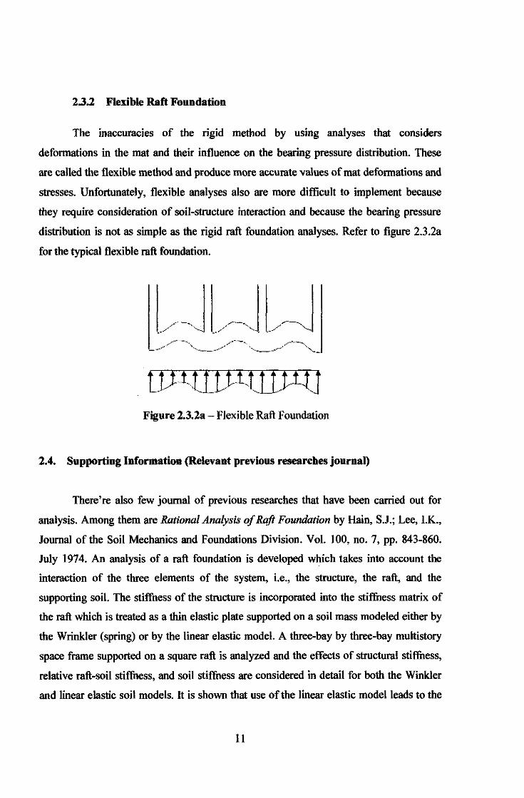
2.3.2 Flexible Raft Foundation
The inaccuracies of the rigid method by using analyses that considers
deformations in the mat and their influence on the bearing pressure distribution. These
are called the flexible method and produce more accurate values of mat deformations and
stresses. Unfortunately, flexible analyses also are more difficult to implement because
they require consideration of soil-structure interaction and because the bearing pressure
distribution is not as simple as the rigid raft foundation analyses. Refer to figure 2.3.2a
for the typical flexible raft foundation.
tiJl.t[tl-tt[tJitJ Figure 2.3.2a- Flexible Raft Foundation
2.4. Supporting Information (Relevant previous researches journal)
There're also few journal of previous researches that have been carried out for
analysis. Among them are Rational Analysis of Raft Foundation by Hain, S.J.; Lee, I.K.,
Journal of the Soil Mechanics and Foundations Division. Vol. 100, no. 7, pp. 843-860.
July 1974. An analysis of a raft foundation is developed which takes into account the
interaction of the three elements of the system, i.e., the structure, the raft, and the
supporting soil. The stiffness of the structure is incorporated into the stiffness matrix of
the raft which is treated as a thin elastic plate supported on a soil mass modeled either by
the Wrinkler (spring) or by the linear elastic model. A three-bay by three-hay multistory
space frame supported on a square raft is analyzed and the effects of structural stiffness,
relative raft-soil stiffness, and soil stiffness are considered in detail for both the Winkler
and linear elastic soil models. It is shown that use of the linear elastic model leads to the
11
conclusion that the settlement profile of a flexible raft is concave, thus there is a transfer
of load to the outer columns compared with a rigid raft. In contrast, the Winkler analysis
predicts a convex settlement profile. Special methods of analysis are developed for rigid
structures and for highly flexible rafts.
The second one, The behavior of an impermeable flexible raft on a deep layer of
consolidating soil by Booker, J R; Small, J C International Journal for Numerical and
Analytical Methods in Geomechanics. Vol. 10, no. 3, pp. 311-328. 1986. In their attempt,
analytic solutions to the problem of the time-settlement behavior of raft foundations have
been limited in the past to flexible or rigid loadings, and have treated the foundation as
being completely permeable. In this paper, solutions are presented for smooth circular
rafts of any flexibility causing consolidation of a deep homogeneous clay layer, where the
raft may be considered permeable or impermeable. Results for the time-dependent
behavior of contact stresses, pore pressures, raft displacements and moment in the raft are
presented. But in this project, the student is focusing on the rectangular raft foundation.
The third one, The Effect of Spread Footing Flexibility on Structural Response by
Sami W. Tabsh, Associate Professor, Civil Engineering Dept., American Univ. of
Sharjah, and 2) Raouf AI Shawa, Project Engineer, ABB Transmission and Distribution,
AI Ghaith Tower, Abu Dhabi, United Arab Emirates; Pract. Periodical on Struct. Des.
and Constr., Volume 10, Issue 2, pp. 109-114 (May 2005). In their attempt, Spread
footings are normally used under individual columns of buildings and bridge piers. They
are economical to use and are applicable for any soil conditions where the bearing
capacity for the applied loads is adequate. Structural design codes and specifications
allow a linear soil pressure distribution to be assumed for the design of spread footings.
This approach is valid for infinitely rigid footings. Past experience has shown that the
assumption of a linear pressure distribution is satisfactory for most footings; however,
there are some cases in which a shallow foundation must be analyzed as a flexible
structure, particularly if the footing is excessively long/wide and thin. In this study, a I
relative stiffuess factor, K'", is developed that can determine whether a footing can be
considered rigid fur the purposes of structural analysis and design. This factor is a
12
modified version of an expression first proposed by Meyerhof in 1953, but takes into
account the size of the column supported on the footing. The study is based on modeling
square and rectangular spread footings subjected to concentric and eccentric loadings by
finite elements. The footings are modeled using thick rectangular plate elements and the I
soil with elastic springs. The results of the study showed that a footing with K" factor
greater than l.O indicates that it can be analyzed as a rigid footing with reasonable
accuracy. This includes determination of soil pressures, vertical footing displacements,
shear forces, and bending moments. The study also showed that maximum shear furces
within a spread footing are less sensitive to changes in the stiffness of a footing than
bending moments.
These journals were found through the journal discovery search engine in the
webpage. From the webpage, the instruction urge the users to seek for the journal in their
respective library in university or others for the full contents of the particular journals.
The full research contents were not in the webpage. However, the journals could not be
found in Universiti Teknologi Petronas Library during the findings. The full texts of the
journals were not available in UTP library including the OPAC. Only a brief description
available for these journals except for the third one in the journal discovery search
engine. These journals help a little bit on this project since several facts were taken and
compared with the current research.
13
CHAPTER3
METHODOLOGY AND PROJECT WORK
3.1. Project identification
Basically, the flow of the project is to study and investigate the behavior of
mat/raft foundation with both approaches rigid and flexible. From an engineering point of
view, the key of this foundation behavior investigation is to know which design approach
is suitable for particular soil properties and any design parameters. The project continued
with the analysis of flexible raft foundation which is being focused in this project. The
analysis of the flexible raft foundation's behavior helps in developing the design work
sheets which act as a program that compute several parameters that important in the
reinforced concrete design afterwards. Next, by using assumption's soil parameters and
design data, one set of result obtained. Manual calculations also were done to compare
with the one computed by the program for the comparison in terms of preciseness. Time
after time, the enhancement of the design worksheets developed were carried out to
improve any weaknesses detected and acquire the most practical program.
The methodology entailed in this research can be sununarized into several steps;
project planning, literature studies, computer program's development, manual
calculations and finally came out with the report and presentation.
3.1.1 Project Planning
• All defined scope and work is outlined along specific time frame to
keep track with on-going and planned activities. It is vital to keep
updates with the outlined activities and its time frame to minimize
behind schedule activities.
• Project planning is very important because sometime whatever that
already planned, not executed as planned because of certain
14
uncertainties. But it doesn't mean that the actual tasks need to be
Jagged behind the schedule because of this. There's lot of ways to
overcome this. Probably, the tasks were conducted according to the
current condition, availability of material, limitation and others.
Therefore, prevention it is always better than cure. The project needs
to be plauned properly.
• For this Final Year Project, the plauning part was done accurately to
make sure the progress of the project run smoothly. Although the
author took quite plenty time for the planning part initially, the result
yield a positive progress of the project. The project run smoothly
according to the schedule and completed succesfully.
3.1.2 Literature Study
• Most of the information was gathered from technical handbooks,
journal, internet/websites and library and through discussion with
supervisor and colleagues. This includes the basics of foundation and
any other relevant and related theories regarding the flexible and rigid
approaches of raft foundation. The studies were done precisely
towards flexible raft foundation analysis in order to develop the it's
design work sheets.
• Available research (journals as supporting information) by individual
on related topics serves as a useful reference for basic of
understanding.
• In addition to that, practices and tutorials of the related program
applications and skills enhancement were carried out with reference to
the proper chaunels and expertise.
• The information which have been gathered and studied includes all the
related theories and concepts were applied to develop the design work
sheets.
15
3.1.3 Computer Program Development and Software Usage
• The design work sheets of flexible raft foundation based on beams on
elastic foundation were developed using the excel spreadsheet program
for the project
• The purpose is to determine all related parameters for the foundation
analysis in the fastest way, time saving and precise answers. There are
not much software available for the flexible foundation analysis
compared to the rigid foundation analysis. Therefore creating own
spreadsheet with reference to the establish theory, the concept is as
same as the software and the analysis could be carried out. Hence, by
inserting any particular soil parameters and raft foundation design
data, the result could be determined easily and fast.
• For the Final Year Project I, tutorial on basis of spreadsheet program
development was learnt through the handbooks and excel website.
They include all the application of inserting formulae, functions,
numbers, and many other useful features. Many spreadsheets were
developed during the basis learning as the practices approach. The
student also being asked by the supervisor to master the excel program
especially in the function usage and inserting formulae. These are very
important since sometimes, there is a case with several assumptions
and different condition to be met. Here, the IF-ELSE function is very
important since there are many conditions of mathematical functions.
This also ensures the ease of the user in terms of inserting the inputs
data without confuse and no need to think much. Means that,
everything already prepared and the user only inserting data according
to the stated instruction.
• For last semester (FYP I) also, few spreadsheets already developed for
flexible analysis. However, the work sheets still need an improvement,
expansion and continuation time after time.
16

• Therefore this semester for Final Year Project II (FYP II), the design
work sheets were improved to obtain the more practical program.
• Improvements were made according to the latest fingdings,
wekneasses detected and based on the matters which have been raised
up by the panels in the FYP I presentation last semester.
3.1.4 Manual Calculations
• The analysis of this project also being carried out in term of manual
calculations.
• The purpose is to compare with the result computed by the computer
program in term of result's precision, checking mistakes and ensured
that the formulae applied were correct. Perhaps to prove that the
manual calculations were more complicated, long and consume more
times.
3.1.5 Report
• Reports were produced as a requirement of the study and as a platform
for discussions, findings and future references.
• For the FYP I in last semester, the author submitted weekly reports
every week to the supervisor for progress supervision. With that also,
the preliminary, progress I and interim report were partially submitted
throughout the last semester as a requirement for final year project.
• While for FYP II, same like the previous semester, weekly reports
were submitted every week for progress supervision .. Progress report I
and progress report II were partially submitted to report the latest
findings and discussions. Full dissertation report are completed and
submitted at the end of this semester for evaluation purpose and to
conclude the project.
17
3.1.6 Presentation
• Presentation also made to the supervisor for each research and fmdings
during the meeting to ensure the rightness and smooth progress flow
• For the FYP I in last semester, the author attended a presentation
regarding the research that have been done throughout the semester.
The presentation was judge by the author's supervisor and UTP
internal panels.
• This semester in FYP II, the author will attend the final presentation to
present his completed project as well as the product. Evaluation will be
done during the presentation as the fmal year project's requirement.
3.2. Tools I Equipment Used
3.2.1 Tools
I) PC Pentium 4 (as a medium for computer program and software usage)
3.2.2 Software
I) Excel Spreadsheet Program [as the interface program (spreadsheet) for
the analysis especially flexible foundation analysis].
18
CHAPTER4
RESULT AND DISCUSSION
This chapter discussed on the findings during the research from last semester until
up to this date. The discussion includes the analysis of flexible raft foundation based on
beams on elastic foundation, theories involve in determining the modulus of subgrade
reaction, k., moment, shear and deflection of the foundation and any other theories
related in flexible analysis. The flow of the design work sheets development and samples
also discussed in this chapter.
4.1. Findings and Discussion
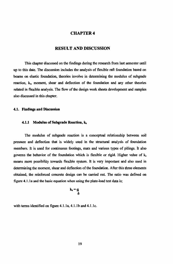
4.1.1 Modulus of Subgrade Reaction, k.
The modulus of subgrade reaction is a conceptual relationship between soil
pressure and deflection that is widely used in the structural analysis of foundation
members. It is used for continuous footings, mats and various types of pilings. It also
governs the behavior of the foundation which is flexible or rigid. Higher value of k,
means more possibility towards flexible system. It is very important and also used in
determining the moment, shear and deflection of the foundation. After this three elements
obtained, the reinforced concrete design can be carried out. The ratio was defined on
figure 4.1.1 a and the basic equation when using the plate-load test data is;
k.=g li
with terms identified on figure 4.l.la, 4.l.lb and 4.l.lc.
19
Pressure, a
'
/ ' ' '
' ' ' ' ,, : Aa ,' '
,1.-----.!
," A.O
' '
Deformation, li
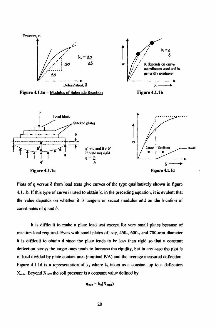
Figure 4.1.1a- Modulus of Subgrade Reaction
p Load block
Stacked plates
-------------------------r---''-
q'
Figure 4.1.1c
q';Cqandll;Cil' if plate not rigid q=_e
A
i . ' . : . ' ' ' . '
' ' •• ' ' ' ' . ' ' ' ' '
' ' ' ' ' ' k,=g
li
K depends on curve coordinates used and is generally nonlinear
3-
Figure 4.l.lb
i 3-
Figure 4.1.ld
Plots of q versus li from load tests give curves of the type qualitatively shown in figure
4.1.1 b. If this type of curve is used to obtain k. in the preceding equation, it is evident that
the value depends on whether it is tangent or secant modulus and on the location of
coordinates of q and li.
It is difficult to make a plate load test except for very small plates because of
reaction load required. Even with small plates of, say, 450-, 600-, and 700-mm diameter
it is difficult to obtain d since the plate tends to be less than rigid so that a constant
deflection across the larger ones tends to increase the rigidity, but in any case the plot is
of load divided by plate contact area (nominal PIA) and the average measured deflection.
Figure 4.l.ld is a representation of k. where k. taken as a constant up to a deflection
Xmax. Beyond XIIUIX the soil pressure is a constant value defmed by
20
Xmax

One of the early contributions was that ofTerzaghi (1955), who proposed that k.
for full-sized footings could be obtained from plate-load tests using the following
equations;
k. = kt !h , for footings on clay B
k. = k1(B + B,)2 , for footings on sand
2B
k. = kt m + 0.5 , for rectangular footing on stiff clay or medium dense sand 1.5m (dimensions, B x L with m = LIB)
where; k, = desired value of modulus of subgrade reaction for the full-size fdn. kt = value obtained from a plate-load test using a 0.3 x 0.3 or other size
However, these three equations are presented primarily for historical purposes and
not recommended for general use.
In 1961, Vesic proposed that the modulus of subgrade reaction could be computed
using the stress-strain modulus Es as;
k',=0.65ti.J~B4 ~
Erlr 11'
k. can be obtained from k', as;
where; E., Er = modulus of soil and footing
k.=~ B
B, Ir = footing width and its moment of inertia based on cross section (not plan)
Since the twelfth root of any value x 0.65 will be close to 1, for all practical
purposes the Vesic equation reduces to;
k.= E. B(1- p2)
p = poisson ratio of soil
From part settlement MI, allowable pressure q. and stress-strain modulus E., few
equation which are;
Ml = qo B' .l::..Jt.mls IF E,
21
E's = 1- 112
E,

AH1 = !11Q B'l ml~ 1111 E'82
AH, qot B't mist bt E'st qo2 = qot B', misdFt E'!ll
B' 2 mls2 IF2 E' S2
Can be rearranged and become;
AH=AqBE'smlslF
Since k. is defined as Aq I AH, obtain;
where,
k.=-~1 __ BE'smlsiF
k. = modulus of subgrade reaction B = Base dintension of foundation
units kN/m3 (SI) eqn. 4.l.la
E' s =Modulus elasticity of soil with effect of poisson's ratio m =Numbers of comers contributing to settlement AH Is, IF = Influence factors which depend on L' IB', thickness of stratum H,
Poisson's ratio 14 and base embedment depth D
This is the most general and recommended equation to be used to determine the modulus
of subgrade reaction and also be compared by k.,sF based on safety factor (developed
after recognizing that bending moments and the computed soil pressure are not very
sensitive to what is used for k. because the structural member stiffuess is usually I 0 or
more times as great as the soil stiffuess);
k. = 40(SF)q. units kN/m3 (SI) eqn. 4.l.lb
where, q. = allowable bearing pressure SF = safety factor
22

4.1.2 Other related parameters
Actually, there are still many other parameters that need to be determined first to
obtain the modulus of subgrade reaction and the one to be used in the calculations.
4.1.2.1 k. for centre and comer
From the eqn. 4.1.2a, there were few complicated parameters to be determined
first before the modulus of subgrade reaction can be obtained. There are the E'., m, Is and
IF. This k, need to be determine for the centre and corner. The description and formulae
are such below:-
from eqn. 4.l.la , k, = -=:-c=:-'1---..,.-.,BE's mls IF
a) Steinbrenner influence factor, Is= l1 + I1:li!J. lz
1- p
l1 =! [MIn (1+ iM2+1l~ iM2+N2) +In <M+iM2+1)( il+N2
)]
1t M(l+ iM +N2+1) M+(iM2+N2+1)
where, M=L' N=H B' B'
For center; For corner; B' =B/2 B'=B L' =L/2 L'=L
This Steinbrenner influence factor, Is also can be obtain through the table 5.2
(Joseph E. Bowles), but the process is even more complicated than using the formulae
above.
23

b) Fox influence factor, IF= no formulae available, need to use the figure 4.1.2.la
~d--+---,--~---i
-~--r-~--~-----1
"' N
Depth ratio. D/B
Figure 4.1.2.1a- Fox Chart to determine IF (figure 5-7 in Joseph E. Bowles)
c) Numbers of corners contributing to settlement MI, m; Centre, m = 4 Side, m =2 Corner, m= 1
d) Modulus Elasticity of soil with effect of poisson's ratio, E' s = 1- 112
E,
* After all parameters above obtained, and then the ks for corner and centre can be determined.
4.1.2.2 k. weighting
This ks can be find after the ks for corner and centre already obtained;
k. wdgbtillg = (4 ksfcentre) + k.,(comer)] 5
24

4.1.2.3 k. sF based on safety factor
from eqn. 4.1.1 b, k. = 40(SF)qa
Allowable bearing pressure of soil, q. is one of the inputs data that need to be
inserted in order to obtain the modulus of subgrade reaction, k.. It is use to find the ks
based on safety factor which is used to compare with the k. weighting. The comparison is
to find the average ks. Based on Terzhagi;
Based on Vessic;
quit= c NcSc + q..,rNq + s.,y B Ny
q. = q.uiS.F
quit= c NcSclk + qbarNqsqdq + O.S y' B Nys.,dy
q. = q.u/S.F
Both are the established equation but the Vessic equation is more updated and
latest compared to Terzhagi. Several coefficient and parameters need to be computed to
obtain the allowable bearing pressure, q •. It is not a simple parameter that people can
assume or something. It needs to be determined following the true condition of the
particular soil to be chosen. Therefore it helps much in saving time and avoid calculation
mistake to develop a design worksheet for q. determination. The Vessic method were
used in the calculation of bearing capacity to determine the modulus of subgrade reaction
in the design worksheets.
25

4.1.2.4 k. Average
This is the final modulus of subgrade reaction which is the average of ks
weighting and ks based on safety factor. ks average is the value that will later used to
determine the moment, shear and deflection of the foundation. It can be concluded such
below:-
k. avenge = I!., weighting+ k. SF
2
Table below are taken from the reference book and consist of established value of ks
according to soil types. It can be used for guidance and comparison when using
approximate equations
Table 4.1.2.48 : Range of modulus of subarade reaction. ko
Soil k. kNim3
loose sand 4800-16000 Medium dense sand 9600-80000 Dense sand 6400D-128000 Clayey medium dense sand 32000-80000 Silty medium dense sand 24000-48000 Clay soil:
q8 S200kPa 1200D-24000
200 < q. s 800 kPa 2400D-48000
q. > 800 kPa >48000
4.1.2.5 k. Critical or Maximum
ks critical is determined from the maximum value obtained among the k. average
of few soils sample which are considered in the analysis. The maximum value will be
considered as the critical value of the modulus of subgrade reaction and will be used in
the next calculations to determine the moment, shear and deflection. This feature of
selecting the k. Maximum already included in the design worksheets as part of improvement.
26

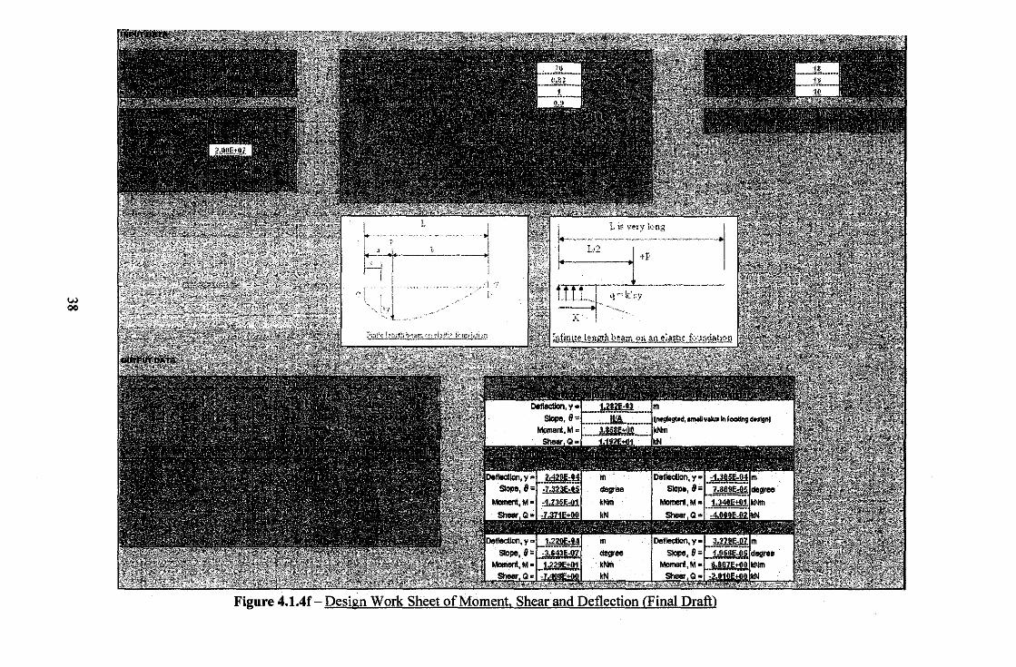
4.1.3 Moment, Shear and Deflection
These three parameters, moment, M; shear, Q; & deflection, y are the most
important parameters that need to be determined as the foundation design using fleXIble
approach. When flexural rigidity of the footing is taken into account, a solution can be
used that is based on some form of a beam on an elastic foundation. This may be the
classical Winkler solution of about 1867, in which the foundation is considered as a bed
springs ("Winkler foundation").
The classical solutions, being of closed form are not so general in application as
the finite element method. The basic equation is
l El~=q=-k'.y where k' s = k.B (This showed the modulus of subgrade reaction is very important to be
determined ), figure 4.1.3a. In solving the equations a variable is introduced:
t
B
U.= 4...Jk'.L4
4EI
-q=ksy
Figure 4.1.3a - ~.=..ks!:} (includes effect of B)
There are 2 condition in determining the moment, shear and deflection; a) Finite length
beam on elastic foundation (Hetenyi 1946) and b) Infmite length beam on an elastic
foundation with mid or center loading (Winkler 1867)
27
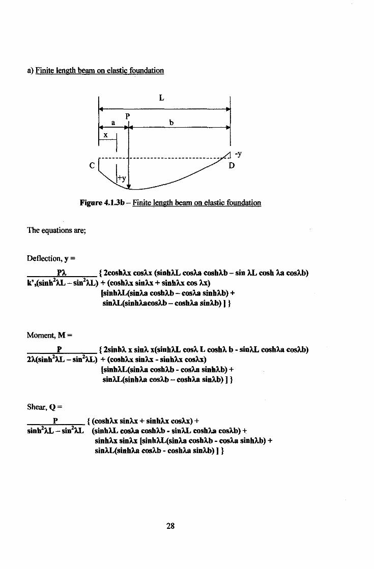
a) Finite length beam on elastic foundation
L
p b
-y
c
Figure 4.1.3b - Finite length beam on elastic foundation
The equations are;
Deflection, y =
PA. { 2coshh cosh (sinhAL cosA.a roshA.b - sin AL cosh A.a cosA.b) k' ,(sinh2AL- sin2AL) + (coshh sinh+ sinhh cos h)
[sinhAL(sinA.a coshA.b- cosA.a sinhA.b) + sinAL(sinhA.arosA.b- coshA.a sinA.b) ] }
Moment,M=
P { 2sinhA. x sinA. x(sinhAL rosA. L roshA. b- sinAL coshA.a cosA.b) 2A.(sinh2AL- sin2AL) + (roshh sinh- sinhh cosh)
[sinhAL(sinA.a coshA.b- cosA.a sinhA.b) + sinAL(sinhA.a cosA.b- coshA.a sinA.b)] }
Shear,Q=
P { (coshh sinh+ sinhh cosh)+ sinh2AL- sin2AL (sinhAL rosA.a coshA.b- sinAL roshA.a cosA.b) +
sinhh sinh [sinhAL(sinA.a coshA.b - cosA.a sinhA.b) + sinA.L(sinhA.a rosA.b- coshA.a sinA.b)] }
28
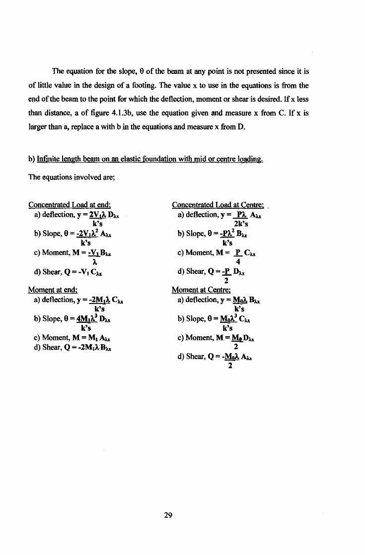
The equation for the slope, 9 of the beam at any point is not presented since it is
of little value in the design of a footing. The value x to use in the equations is from the
end of the beam to the point for which the deflection, moment or shear is desired. lfx less
than distance, a of figure 4.1.3b, use the equation given and measure x from C. If x is
larger than a, replace a with bin the equations and measure x from D.
b) Infinite length beam on an elastic foundation with mid or centre loading.
The equations involved are;
Concentrated Load at end: a) deflection, y = 2V,A. DM
k's b) Slope, 9 = -2Vti..Z AM
k's c) Moment, M = -V! BM
A. d) Shear, Q = -Vt eM
Moment at end: a) deflection, y = -2MtA. eM
k's b) Slope, 9 = 4M1A.3 DM
k's c) Moment, M=Mt~ d) Shear, Q = -2MtA.BM
Concentrated Load at Centre: . a) deflection, y = PA. AM
2k's b) Slope, 9 = -PA.2 BM
k's c)Moment,M= g_eM
4 d) Shear, Q = -P DM
2 Moment at Centre:
a) deflection, y = ~ BM k's
b) Slope, 9 = ~3 eM k's
29
c) Moment, M =MIL DM 2
d) Shear, Q = -MoA. AM 2
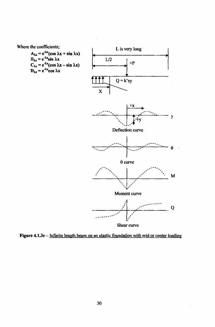
Where the coefficients;
A1x = e·h(cos A.x +sin A.x) B1x = e ·1xsin A.x ch = e'h(cos A.x- sin A.x) D1x = e ·1xcos A.x
L is very long
U2 ~--------~ +P
X
+x ........... -- ....... , ... -- .......
' ' '
Deflection curve
9curve .. -....
..... ,........ .... .....
y
..... , ...
---------·~-~~--~-·-· __________ · ~ ' / ', '
' / ' '
~oment curve
---:-'-',:+-.'1 ..:___.------_-----_-- Q ,' ,' ________ ....... /,
' Shear curve
Figure 4.1.3c- Infinite length beam on an elastic foundation with mid or center loading
30
4.1.4 Excel Spreadsheet Program Practices and Development
Throughout the last semester, the author was asked by the project's supervisor to
learn the basis of the Excel program, practice on how to insert variety of complicated
formulae into the program to develop the solution in the easiest way, developing a simple
spreadsheet program and others.
The practices were carried out with reference to excel books, tutorial in Excel.
websites and also from colleagues. Basic of Excel include; function; [Sum, Average,
Count, If, Max, Hyperlink, Sin and many others], Manage excel into appropriate and
readable database, inserting formulae and etc.
All the related formulae were extracted and transferred to the Excel program to
develop the design work sheets. The main aims are to obtained the deflection, moment
and shear for the flexible foundation design of finite and infinite beam. These three
parameters are the main important thing in designing a flexible foundation. In obtaining
these three parameters, there are several other parameters that need to be obtained first
which have been discussed before. The sequence in obtaining the parameters until fmally
getting the moment, shear and deflection of the design flexible foundation is related to
each other. The author's aim is to prepare a spreadsheet that can generate result of the
analysis with only a few inputs of data. Therefore, a combination of few sets of
spreadsheets into a single spreadsheet could decrease the inputs of data and hence, save
much more time of the users.
With all the researches that have been done during last semester in FYP I, the
author had developed few spreadsheets for the first draft on how to obtain the k,,
moment, shear and the deflection and all parameters involved in the analysis by just
inserting few parameters of the foundation and soil properties. The design worksheets
only considered one type of soil data to be analyzed. Any references that needed in the
calculations and could not be calculated by the program were prepared in the design
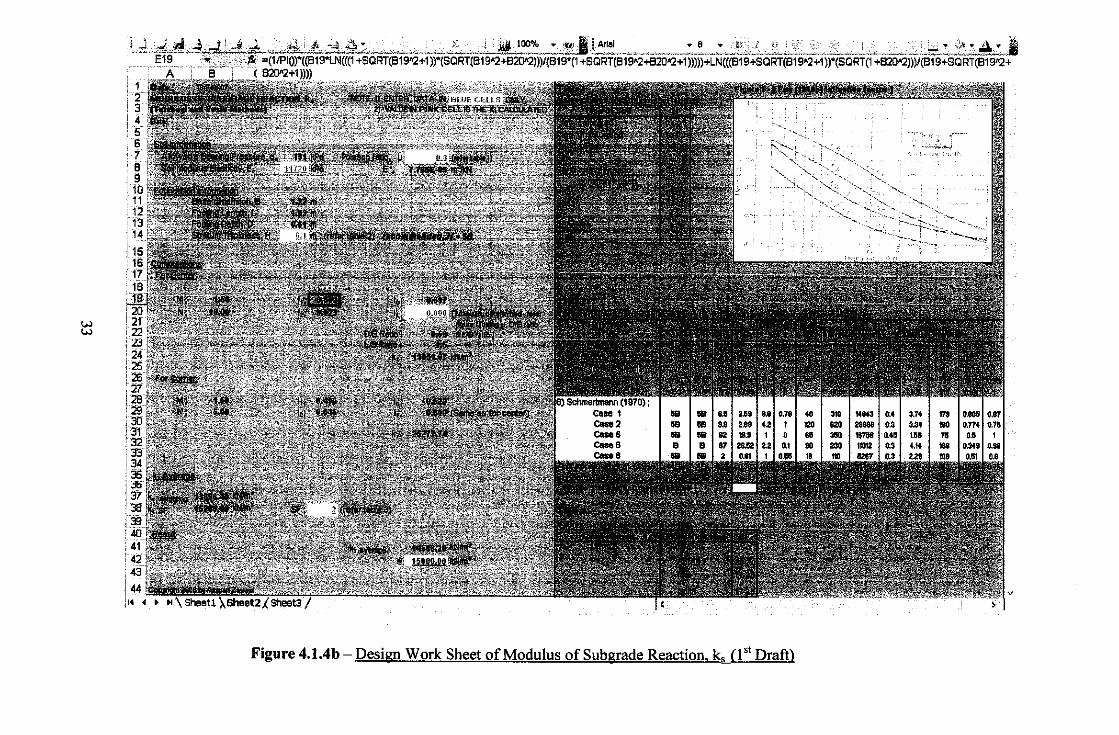
worksheets. Enclosed below are the first draft of the design worksheets development:-
31

Nc• 1Ui1
••• 1.216
••• 1.2 Nr• $.SIS
j1~~~~~l\l -"~"'~-~- ·~ s,= t.Ut w
N ~~' - ' .: > •' JJlUf.,..)§.,;;;:,~.. ""- ,_,1/i,~~ •• _:_;Z;:.._ .. = 1 •• ...... .., •• M
Figure 4.1.4a- Design Work Sheet of allowable bearing pressure. q@ (1 51 Draft)
w w
...... _
,, -·-·-· k....,_~_;
" ... ~. ,.,.,,
·,~,, >'-~.;:,_ - .
'..... '-....: ..........
1",. '· .•• ·~:~t:~:=---."
Figure 4.1.4b- Design Work Sheet of Modulus of Sub grade Reaction. k, (1" Draft)
v
w
""" I . t<~"-- --:--~------ -· -~- ----~---+
:.. -='---~ ~. •
··:
·_, i::"'
:ot-- v: ! +I'
+_ -fJlfT .,~k· Y ~-·
~C-' '---~· -"o.---
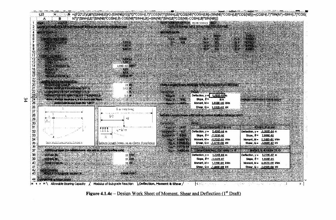
Fhzure 4.1.4c - Design Work Sheet of Moment. Shear and Deflection (1 '' Draft)

The spreadsheets contain several steps and formulae in determining the important
parameters for flexible foundation analysis with some reference table and figure for the
input value in blue. The cell in pink showed the calculated value for each worksheet.
Each of worksheet was in separate for the initial development. Throughout the
enhancement of these spreadsheets, they have been combined together so that the input
value could be decreased and hence, result with time saving and more practical.
Furthermore, there will be no repetition for the input value. As descn"bed befure, the
development of the first draft design worksheets only considered one type of soil data to
be analyzed. This will limit the usage of this design worksheets since in terms of logical
aspect, there are always more than one type of soils exist in any particular area.
Therefore, in FYP II for this semester, the design worksheets have been
enhanced. Consideration made for few types of soil. The design worksheets allowed
maximum of six types of soils at any particular area to be considered in the analysis. The
determination of moment, shear and deflection would take the maximum value of
modulus of subgrade reaction obtained among the soils. The maximum value will be
considered as the critical one. This means that the RC design later will be safe since the
critical value of the present soils was taken into consideration.
Same like the previous one, the separate design workheets of bearing capacity,
modulus of subgrade reaction and moment, shear and deflection determination were
combined into one. The combination made to reduce the user's data input by avoiding
repetition of the input value. In addition, the input slots have been rearranged to ease the
user in inserting the input data organizely. The input slots were rearranged to the top side
of the design worksheets. All the computations done by the design worksheets also were
rearranged in organize way to make sure the result data that computed easy to be read and
checked. The final design work sheets attached as below:-
35

..., 0\
Figure 4.1.4d- Design Work Sheet of allowable bearing pressure. g~ (Final Draft)
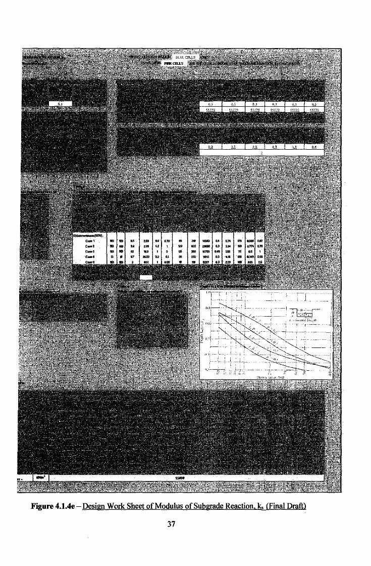
Figure 4.1.4e- Design Work Sheet of Modulus of Subgrade Reaction. k, (Final Draft)
37
w ""
b L. ji ~ .:. ,, ~;
.. I i '
,A•l ~ _/I
. . ' .l
I L ~~ \<~:)' k·llg l ~~~ -1~~ ---]_:- .. --~ ~ I· - - +~" _______ _
m:r ;f .;: , .. " l. I
Figure 4.1.4f- Design Work Sheet of Moment, Shear and Deflection (Final Draft)
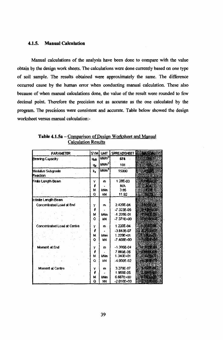
4.1.5. Manual Calculation
Manual calculations of the analysis have been done to compare with the value
obtain by the design work sheets. The calculations were done currently based on one type
of soil sample. The results obtained were approximately the same. The difference
occurred cause by the human error when conducting manual calculation. These also
because of when manual calculations done, the value of the result were rounded to few
decimal point. Therefore the precision not as accurate as the one calculated by the
program. The precisions were consistent and accurate. Table below showed the design
worksheet versus manual calculation:-
Table 4.1.Sa- Comparison of Design Worksheet and Manual Calculation Results
Concentrated Loed at End 'I m 2.429E-04 e •7.323f.Q5 M kNrn -1.235f-01 Q kN -7.371 E+OO
Concentrated Loed at Cenlu> y m 1.220E-04 e -3Jl43f-07
M - 1.229E+01 Q kN -7 .40SE+Il0
MO!r!eOI at End y m -1.305f-04 , 7869E-OS M - 1 :340E+01 Q kN -4 .OOOE-02
MO!r,enlatCentre y m 32791:-07 , 1.95llf-OS M - 6.667E+OO Q kN -2.010E+00
39
CHAPTERS
CONCLUSION AND RECOMMENDATION
5.1. Conclusion
As a conclusion, the selection of raft foundation, one type of shallow foundation
in design should be publicized to reduce cost in construction instead of using piling
system that is far more expensive. Therefore the studies and research of this project
focusing on the raft foundation behavior to introduce its usage and applications, enhance
and publicize the knowledge of it. As long as the design is acceptable for a particular soil
condition, there's no doubt of using this approach. The objectives of the project were
successfully achieved. The design work sheets for analysis of flexible rafts based on
beams on elastic foundations were fully developed. The weaknesses which detected in
the first design worksheets were encountered and improved in the final design
worksheets. The author feels that the design worksheets that already developed are
practical and can he used to ease out the user's or designer's works in designing a
shallow foundation that is the flexible raft foundation.
5.2. Recommendation
The design worksheets according to the author's Final Year Project scopes were
completed accordingly. However, the input data can be reduced more in the future to
enhance the efficiency of this design worksheets. For example, the modulus elasticity of
soil, E,. Soil data from field test from geotechnical investigation needed in the
determination of E, such as standard penetration test. From these data, there is still
several steps to determine the E, and involving lots of formula and complex mathematical
function. If the worksheets can include the determination of this E. or make it simpler to
be determined, it is better and can save more times for the users. Same goes to other input
data, if possible to be reduced, the design worksheets will be more efficient and better.
40
Afterall, part of the project's o~ectives was to reduce the input data as much as possible
and hence, saving time.
This design worksheets were developed based on the theory and concept.
However, it still need to be applied to the real design of foundation to test on it's
effectiveness. With the actual soil parameters at the considered design site, the result of
the design worksheets computations will be used for the RC design of the foundation. At
the same time, the common way to determine the same parameters are carried out to
compare with the design worksheets. From this mehod, the efficiency of the design
worksheets can be determined.
This design worksheets were developed a little bit with reference to the reinforced
concrete council design work sheets. Based on the author's research, the the design
worksheets for flexible raft foundation still not exist. Perhaps, through all
recommendations which are discussed before will bring the author's design worksheets to
complete the lacking.
41
REFERENCE
1) "Foundation Analysis & Design", by Joseph E. Bowles, P.E, S.E, 5th Edition,
McGraw-Hill International Edition
2) "Foundation Design (Principles and Practices)", by Donald P. Coduto, 2nd Edition,
Prentice-Hall, Inc.
3) "Principles of Foundation Engineering", by Braja M. Das, 4th Edition, PWS Publishing
and ITP Company.
4) "Soils and Foundations", by Cheng Liu and Jack B. Evett, 5th Edition Prentice_ Hall,
Inc.
5) "Shallow Foundations (Bearing Capacity and Settlement)", by Braja M. Das, 1st
Edition, CRC Press.
6) A.P Dr. Nasir Shafiq, Lecturer @ FYP Supervisor, School of Civil Engineering,
Universiti Teknologi Petronas, Tronoh,Perak Malaysia
7) 7 July 2006 <www.csa.com/csa illumina guide discovery/>, Rational Analysis of Raft
Foundation by Hain, S.J.; Lee, I.K., Journal of the Soil Mechanics and Foundations
Division. Vol. 100, no. 7, pp. 843-860. July 1974.
8) 7 July 2006 <www.csa.com/csa illumina guide discovery/>, The behavior of an
impermeable flexible raft on a deep layer of consolidating soil by Booker, J R; Small, J
C International Journal for Numerical and Analytical Methods in Geomechanics. Vol.
10, no. 3, pp. 311-328. 1986.
9) The Effect of Spread Footing Flexibility on Structural Response by Sami W. Tabsh,
Associate Professor, Civil Engineering Dept., American Univ. ofSharjah; and
Raouf AI Shawa, Project Engineer, ABB Transmission and Distribution, AI Ghaith
Tower, Abu Dhabi, United Arab Emirates; Pract. Periodical on Struct. Des. and
Constr., Volume 10, Issue 2, pp. 109-114 (May 2005)
42

10) 9 September 2006 <w,., ''>.s:occgl£,com>
> http:/lwww.selfbuildland.co.uk/Self-Build-Home-Foundations.htm
rigid foundation on homogeneous loose soil
>Texas Tech Universities/Civil Engineering Department/Lecture Notes/Advance
Foundation Design/Shallow Foundation
Tawfiq, pHd, PE.
> http:/lspreadsheets.about.com/
43
APPENDIX
MANUAL CALCULATION
Assumption; 1) Use one sample of data for manual calculation 2) Unit of measurement= S.l 3) Reference for tables and figures; "Foundation Analysis & Design", by
Joseph E. Bowles, P.E, S.E, 5th Edition, McGraw-Hill International Edition
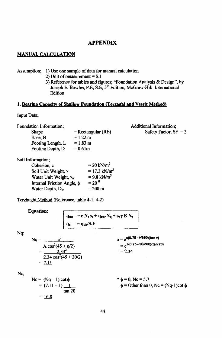
1. Bearing Capacity of Shallow Foundation <Termgbi and Vessic Method)
Input Data;
Foundation Information; Shape Base, B Footing Length, L Footing Depth, D
Soil Information; Cohesion, c
= Rectangular (RE) =!.22m = 1.83 m =0.61m
Soil Unit Weight, y Water Unit Weight, Yw Internal Friction Angle, ~ Water Depth, Dw
=20kN/m2
= 17.3 kN/m3
=9.8kN/m3
=20° =200m
Terzhaghi Method (Reference, table 4-1, 4-2)
Equation;
Additional Information; Safety Factor, SF = 3
q.u = c N.s. + qbarNq + SyyB Ny
q. = q.u/S.F
Nq;
Nc;
Nq= a2
A cos2(45 + ~/2) 2.342
= 2-.-34-co--"';s2;c(4!...5-+_2,...0/-2)
= 7.11
Nc = (Nq -1) cot~ = (7.11-1)_1_
tan20 = 16.8
44
a = ell(O. 75- <l>1360)(tan +l = e"(O. 75- 20/360)(tan 20)
=2.34
* ~=O,Nc=5.7 ~=Other than 0, Nc = (Nq-1)cot ~
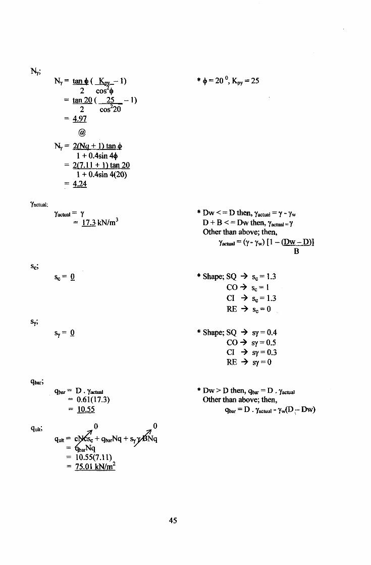
Yactuol;
N1 = tan+(~-1)
2 cos+ = tan20( 25 -l)
2 cos220 = 4.97
@
N1 = 2£Nq + n tan 4> l + 0.4sin 4tjl
= 2(7.ll + lltan20 l + 0.4sin 4(20)
= 4.24
Yactual = Y = 17.3 kN/m3
qbar = D . Yactuol = 0.61(17.3) = 10.55
0 0
quit= c~ + qbarNq + ~q = 'arNq = 10.55(7.11) = 75.01 kN/m2
45
*.!.=20° K =25 'Y ' py
* Dw < = D then, Yactuol = Y - Yw D + B < = Dw then, Yactual = Y Other than above; then,
Yactuol = (y- Yw) [I - (Dw- D)] B
* Shape; SQ ~ sc = l.3 co~ sc=l CI ~ sc= l.3 RE ~ sc=O
* Shape; SQ ~ sy = 0.4 CO~ sy=0.5 CI ~ sy=0.3 RE ~ sy=O
* Dw > D then, qbar = D . Yactual
Other than above; then, qbar = D . Yactuol - yw(D \ Dw)

q. = qu~~/ SF = 75.0113 = 25kN/m2
Note: Since according to the theory, if the shape is rectangular, bearing capacity for Terzhaghi Method will not be available,
quh=N/A q. =N/A
46
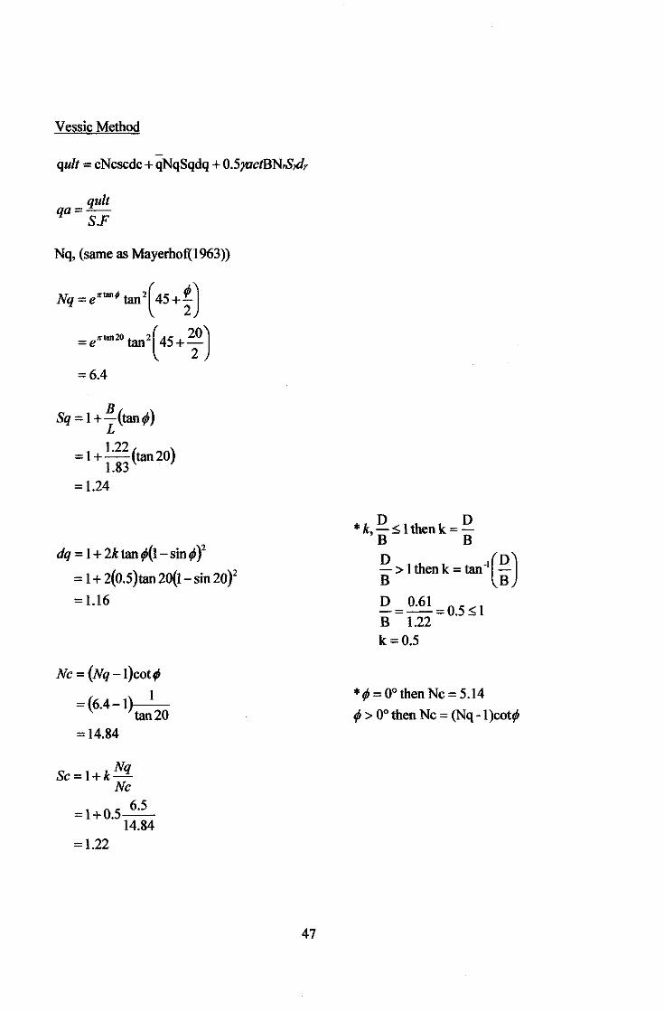
Vessic Method
quit = cNcscdc + qNqSqdq + 0.5JUctBN.S,d,
quit qa=
S.F
Nq, (same as Mayerhof(1963))
Nq = entan; tan2( 45+ ~)
= entan20 tan2( 45 + ~0)
=6.4
Sq=1+B(tan¢) L
= 1 + 1.22
(tan20) 1.83
= 1.24
dq = 1 +2ktan¢(1-sin¢)2
= 1 + 2(0.5)tan20(1-sin20}'
= 1.16
Nc=(Nq-1)cot¢
1 =(6.4-1)
tan20 =14.84
Nq Sc=1+k-
Nc
=1+0.5~ 14.84
=1.22
47
*k D ~1thenk= D 'B B
~ >1thenk=tan·t~)
D = 0.61 =0.5~ 1 B 1.22 k=0.5
*¢ = 0°then Nc = 5.14
¢ > oo then Nc = (Nq -1 )cot¢
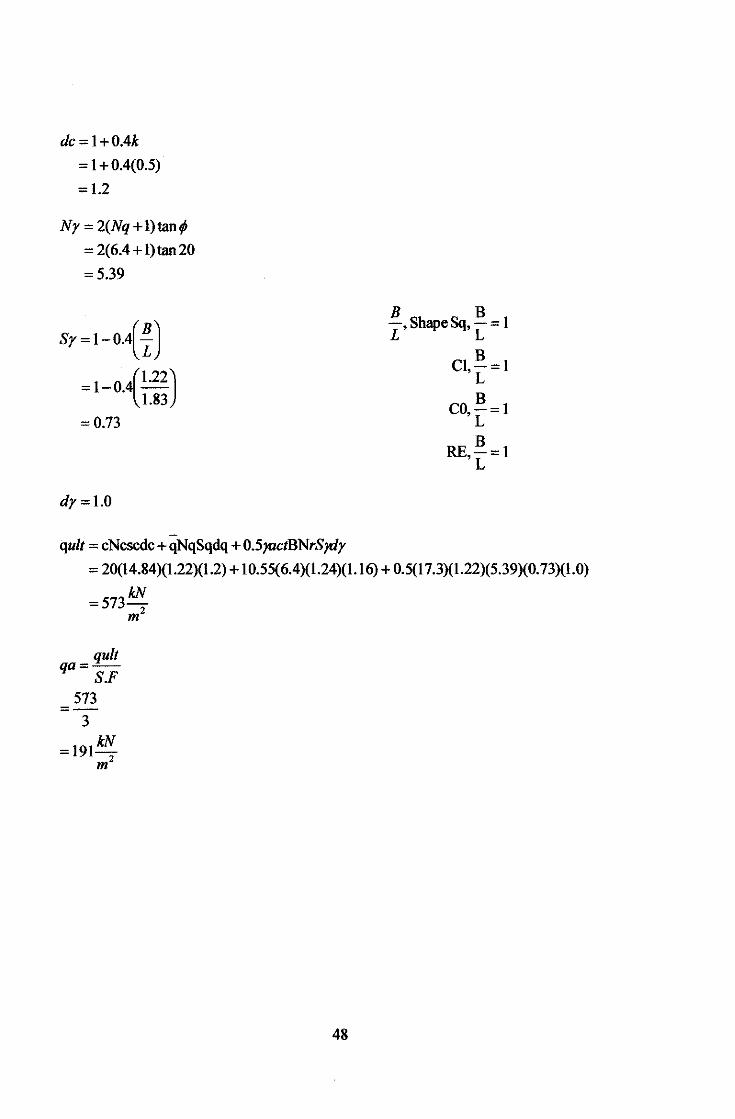
dc=1+0.4k
= 1 + 0.4(0.5)
= 1.2
Ny = 2(Nq + 1)tan¢
= 2(6.4+ l)tan20
=5.39
sr=I-o.{~)
= 1-0.4(1.22) 1.83
=0.73
dy=l.O
quit = cNcscdc + qNqSqdq + 0.5]UctBNrSJdy
B ShapeSq B =1 L' 'L
B C1,-=1
L
CO, B =1 L B
RE,-=1 L
= 20(14.84)(1.22)(1.2) + 10.55(6.4)(1.24)(1.16) + 0.5(17.3)(1.22)(5.39)(0. 73)(1.0)
=573kN m2
quit qa=-
S.F 573
=-3
kN =191-
m2
48

2. Modulus of Subgrade Reaction, Ks
Input data,
Soil information; Allowable bearing pressure, qa = 191 kN/m2 (from previous calculations) Soil modulus elasticity, Es = 11720 kN/m2 Poisson ratio, 11 = 0.3 *table 2-7,pgl23 (clay)
Foundation Information; Base,B = l.22m Length, L = l.83m Depth, D = 0.6lm Stratum thickness,
H=5B
Es'= 1- J.l2 Es
1-0.Y =
ll720 m2
=7.76xl0-5-
kN
1 ks=---
B'E'smlslf
*
= 5(1.22) =6.lm
L' M=B' H
N=B'
* recommended by Joseph e.Bowles H=5B (table 5-3, pg307)
B B'= -(centre),B'= B(corner)
2 L
L'= -(centre),L'= L(corner) 2
49

ks (centre);
M = £= L/2 =!:_ = 1.83 = 1.5 B' B/2 B 1.22
N=H =_!!_=2H =2(6.1)=IO B' B/2 B 1.22
12-10( 1.5 } - 2n IO·A52 + 102 + 1
=0.023
l-2,u Is=ll+--12
1- .u = 0.586 + 1- 2(0.3) (0.023)
1-0.3 =0.599
Jf=0.8 *Figure 5-7 , pg, 303
D ratio= 0·61 = 0.5 B 1.22
l.
!:_ratio = 1.83 = 1.5 B 1.22
.u = 0.3
m; Number of comers contributing to settlement Ml centre,m = 4
m=4 side,m=2
corner,m = l
50
pg306
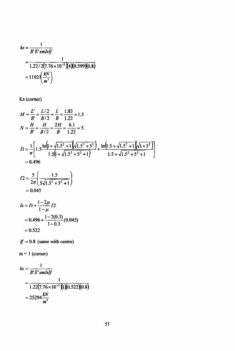
ks = _ __:1:..___
B'E'smlslf
1
= 1.22t2(7.76x 10-5 X4X0.599Xo.8)
=1102{~)
Ks (corner)
M = L' = L/2 = L = 1.83 = 1.5 B' B/2 B 1.22
N= H =_!i_= 2H = 6.1 = 5 B' B/2 B 1.22
/2-5( 1.5 J - 27r 5~1.52 +52+ 1
=0.045
l-2,u ls=Il+--12
1- .u = 0.496 + l- 2(0.3) (0.045)
1-0.3 = 0.522
lf = 0.8 (same with centre)
m = 1 (corner)
ks 1
B'E'smlslf
1
1.22(7.76x 10⁻⁵ XIXO.S22X0.8)
=25294 kN m3
51
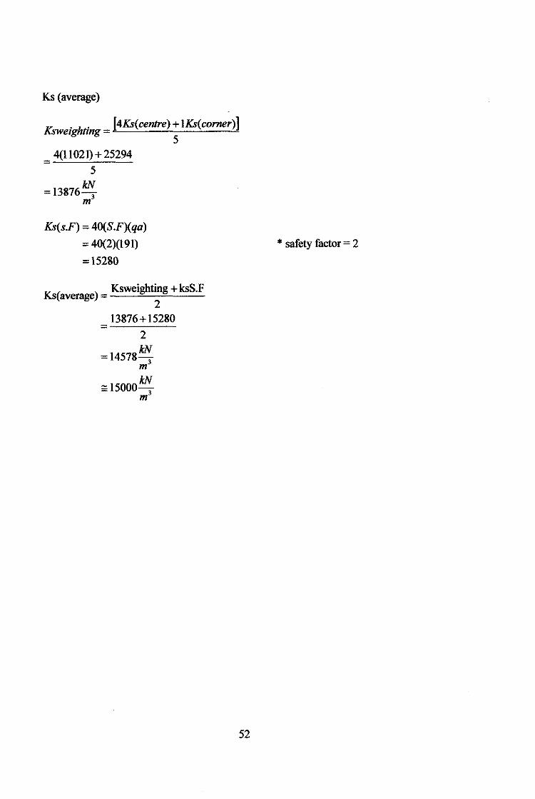
Ks (average)
/(sw, . h . [4KS(centre) + 1KS(comer)] erg. ting =
5 = 4(11021)+25294
5 kN
=13876-m3
KS(s.F) = 40(S.F)(qa)
= 40(2)(191)
= 15280
K ( ) Ksweighting + ksS.F
s average = 2
13876+ 15280 =
2
=14578kN m3
kN =:15000-3
m
* safety factor = 2
52
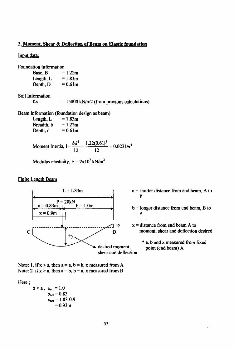
3. Moment, Shear & Deflection of Beam on Elastic foundation
Input data:
Foundation information Base, B = 1.22m Length, L = 1.83m Depth, D = 0.6lm
Soil Information Ks = 15000 kN/m2 (from previous calculations)
Beam information (foundation design as beam) Length, L = 1.83m Breadth, b = 1.22m Depth, d = 0.6lm
M I . I bd3 1.22(0.61)3
oment nertm, = - = --'------'-12 12
0.023lm4
Modulus elasticity, E = 2xl07 kN/m2
Finite Length Beam
L= 1.83m
P=20kN a= 0.83m b = !.Om
x=0.9m 1 I
c --------------r------------------ -- D-y +y
desired moment,
a= shorter distance from end beam, A to p
b = longer distance from end beam, B to p
x = distance from end beam A to moment, shear and deflection desired
shear and deflection
* a, b and x measured from fJXed point (end beam) A
Note: 1. if x :5 a, then a= a, b = b, x measured from A Note: 2 if x > a, then a= b, b = a, x measured from B
Here; x > a , Bact= 1.0
bact= 0.83 Xact = 1.83-0.9
=0.93m
53

Estimate k's, A. and ll.
k's =ksB
= 15000(1.22)
=18300kN mJ
A-= 4~ k's 4El .--:-=-:-:---
= 4 18300 4(2 X 1 07)(0.0231)
=0.32
AL=4M .-------.,...--
= 4 18300(1.83)' 4(2 X 10 7 )(0.0231)
=0.58
Deflection, y;
p.A. y= k's(sinh2 AL-sin 2 A£)
Ax= 0.32(0.93)
=0.3
A.a = 0.32(1.0)
=0.32
J.h = 0.32(0.83)
=0.27
l(2coshAxcoshXsinhALcoskcoshJ.h-sinALcoshAacosJ.h)+ )
{sinhAL(sifiAacoshJ.h-cosksinhJ.h)+]
(coshAxsinh+sinhAxcosh . , rl . . ) sm"'-"'sinhAacosAb-coshAasmAb
For simplification.
a= p.A. k's(sinh 2 AL-sin2 A.L)
b = (2 cosh l!x cos l!x X sinh AL cos A.a cosh J.h -sin AL cosh A.a cos J.h)
c =(cosh .llxsin l!x +sinh llxcos.llx)
d = sinhAL(sinA.acoshJ.h- cosA.asinhJ.h)
e = sin AL(sinh Aa cos J.h - cosh A.a sin J.h)
thus, y=a[b+c(d+e)]
54
a=----~(2~0~)(~0.~32~)~---18300(sinh2(0.58) -sin2(0.58))
=9.31x10⁻⁴
b = (2cosh0.3cos0.3Xsinh0.58cos0.32cosh0.27- sin 0.58cosh0.32cos0.27)
= 1.31
c = (cosh0.3sin0.3 +sinh 0.3cos0.3)
= 0.31
d = sinh 0.58(sin 0.32 cosh 0.27- cos 0.32 sinh 0.27)
=-0.16
e =sin 0.58(sinh 0.32cos0.27- cosh 0.32sin 0.27)
= 5.02x 10⁻⁵
y = a[b+c(d +e)]
= 9.31x 10-<[1.31 +0.31(-0.16+ 5.02x 10⁻⁵ )]
= l.l73x 10-3 m
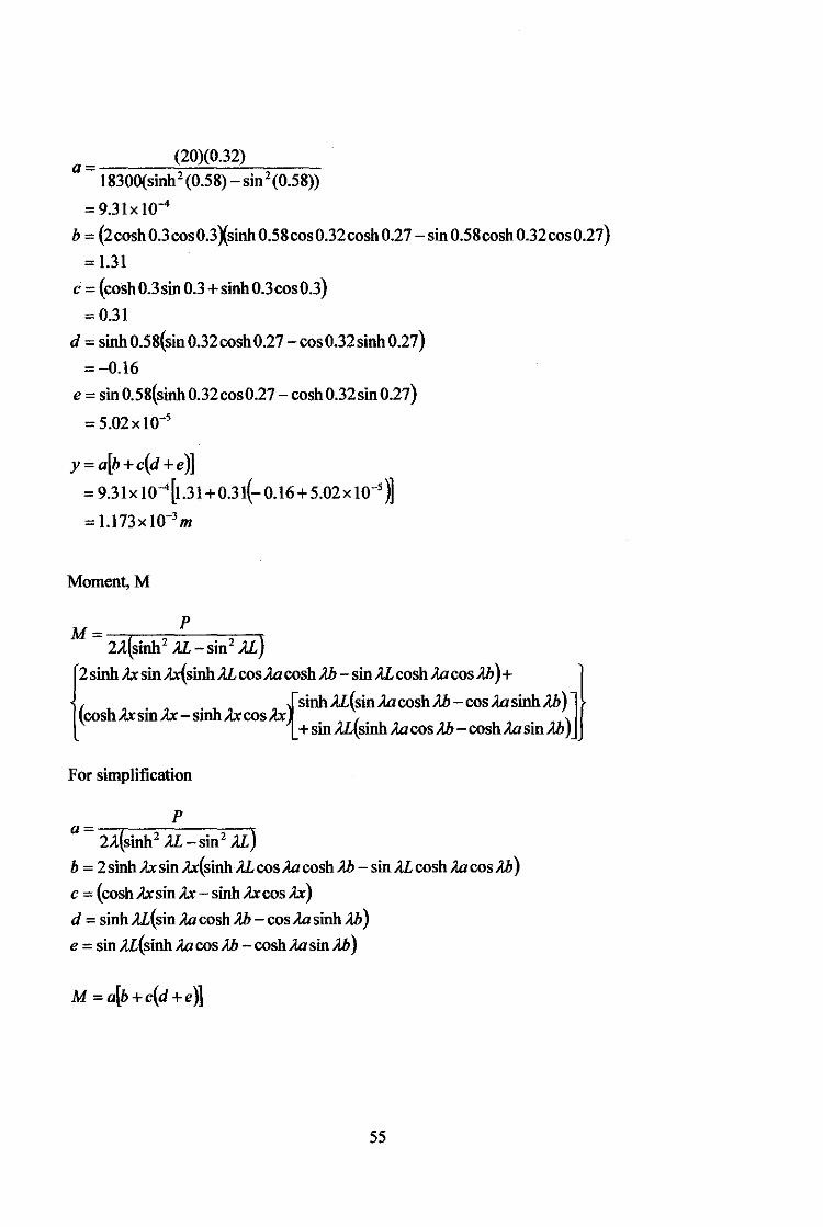
Moment,M
M= p 2A(sinh 2 AL -sin 2 AL}
l2sinhA.xsinA.x{sinhALcos,:WcoshAb-sinALcosh,:WcosAh)+ )
1 {sinhAL(sinAacoshAb-cos,:WsinhAb)J \coshl!xsinA.x-sinhA.xcosA.x
+sin AL(sinh ;{a cos Ab-coshAasinAb)
For simplification
p
a = 2A.(sinh 2 AL - sin 2 AL)
b = 2 sinh l!x sin llx(sinh AL cos Aa cosh Ab- sinAL cosh Aa cos Ab)
c = (coshl!xsinA.x- sinhA.xcosA.x)
d = sinh AL(sin ;w cosh Ab- cos ;{a sinh Ab)
e = sin AL(sinh Aa cos A.b -cosh ,:Wsin Ab)
M = a[b +c(d +e)]
55
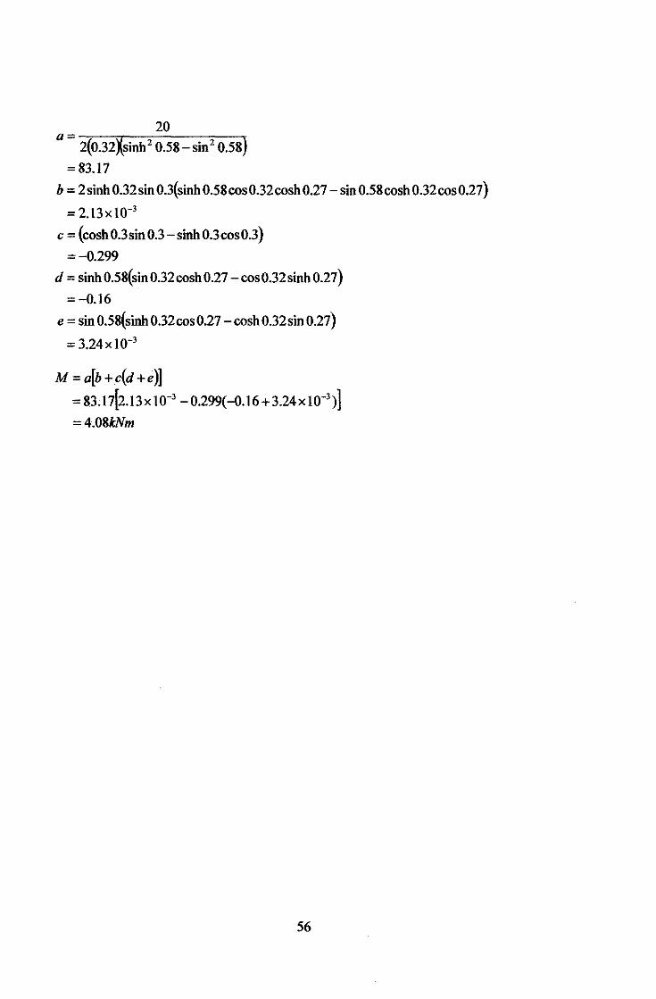
20
a= 2(0.32Xsinh 2 0.58-sin 2 0.58)
=83.17
b = 2sinh 0.32sin 0.3(sinh 0.58cos0.32cosh 0.27- sin 0.58cosh 0.32cos0.27)
= 2.l3x to-3
c = (cosh0.3sin0.3 -sinh 0.3cos0.3)
=-0.299
d = sinh 0.58(sin 0.32 cosh 0.27- cos 0.32 sinh 0.27}
=-0.16
e = sin 0.58(sinh 0.32cos 0.27- cosh 0.32sin 0.27}
= 3.24x10⁻³
M =a[b+c(d +e)] = 83.I7[2.l3x 10-3
- 0.299(-0.16 + 3.24x I0-3)]
=4.08kNm
56
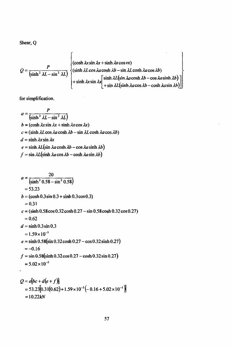
Shear, Q
p (cosh A.xsin A.x +sinh A.xcos vx)
Q= {sinh2 A.L-sin 2 u) (sinh A.Lcos..Wcosh Ah- sin A.Lcosh ..WcosAh)
inh . [sinhA.L(sin..WcoshAh-cos..WsinhAh)J
+s A.xsmA.x +sin A.L(sinh ..WcosAh-cosh ..Wsin Ah)
for simplification.
p
a= {sinh 2 A.L-sin 2 AL)
b = (coshA.xsinA.x+sinhA.xcosA.x)
c = (sinhA.Lcos..WcoshAh -sinA.Lcosh..WcosAh)
d = sinhA.xsinA.x
e = sinh A.L(sin ..W cosh Ah-cos ..W sinh Ah)
f = sinA.L(sinh..WcosAh -cosh..WsinAh)
20 a = -r---=-----=----.:
(sinh 2 0.58-sin 2 0.58)
=53.23
b = (cosh0.3sin0.3+sinh 0.3cos0.3)
=0.31
c = (sinh0.58cos0.32cosh0.27 -sin 0.58cosh0.32cos0.27)
=0.62
d =sinh 0.3sin 0.3
= l.59x 10-3
e =sinh 0.58(sin 0.32cosh 0.27- cos0.32sinh0.27)
=-0.16
f =sin 0.58(sinh 0.32cos0.27- cosh0.32sin 0.27)
=5.02x1o-s
Q=a(bc+d(e+ J)] = 53.23(0.31(0.62)+ l.59x 10-3
(- 0.16 + 5.02x w-s )j = 10.22kN
57
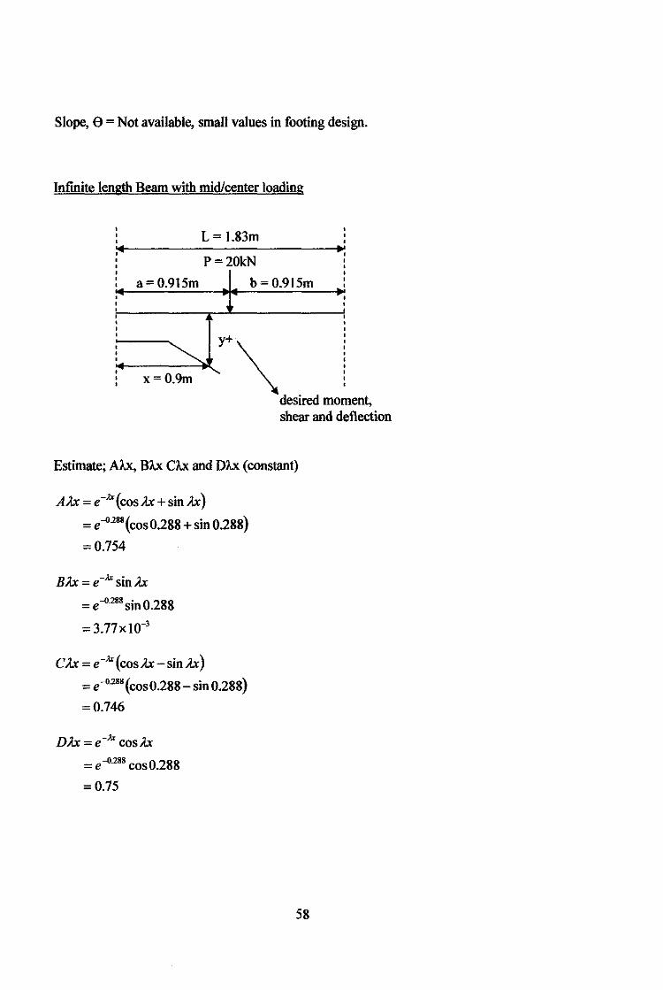
Slope, e =Not available, small values in footing design.
Infinite length Beam with mid/center loading
L= 1.83m
P=20kN
a=0.915m b=0.915m
i+--x-= 0-;---'l~y+ \ desired moment, shear and deflection
Estimate; AA.x, BA.x CA.x and DA.x (constant)
AA.x = e-.a(cosA.x+sinA.x)
= e-0288 (cos0.288 +sin 0.288)
=0.754
BA.x = e-.a sinA.x
= e -0.288 sin 0.288
= 3.77x10⁻³
CA.x = e-.a(cosA.x-sinA.x)
= e-0·288 (cos0.288 -sin0.288)
=0.746
DA.x = e-.a cosA.x
= e-0288 cos0.288
= 0.75
58
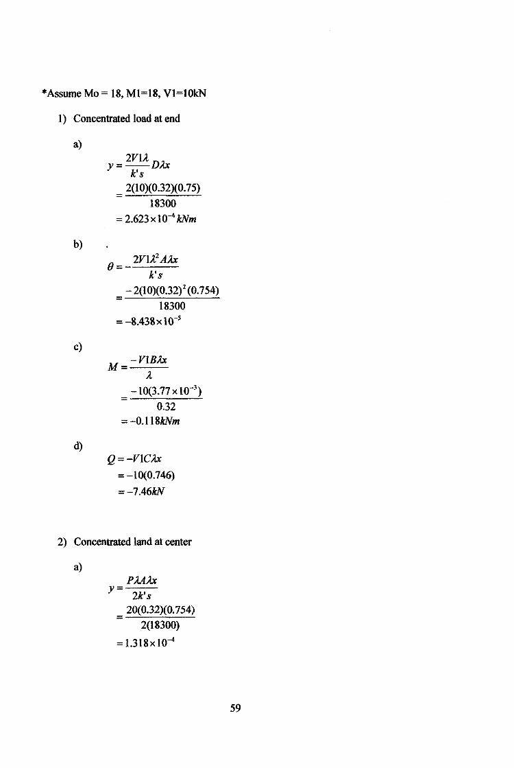
*Assume Mo = 18, M1=18, V1=10kN
1) Concentrated load at end
a)
b)
c)
d)
= 2VU D.?.x y k's
2(1 0)(0.32)(0. 75) =
18300
= 2.623 x 1 0_. kNm
B= 2V1.A? A.?.x
k's
- 2(10)(0.32) 2 (0.754) =
18300
= -8.438 X 1 o-s
M= -VIB.Ax
A. -10(3.77 X lW3
) =
0.32 =-O.ll8kNm
Q= -VIC.?.x
= -10(0.746)
=-7.46kN
2) Concentrated land at center
a) PM.?.x
y= 2k's
20(0.32)(0. 754) =
2(18300)
= l.318x 10-4
59
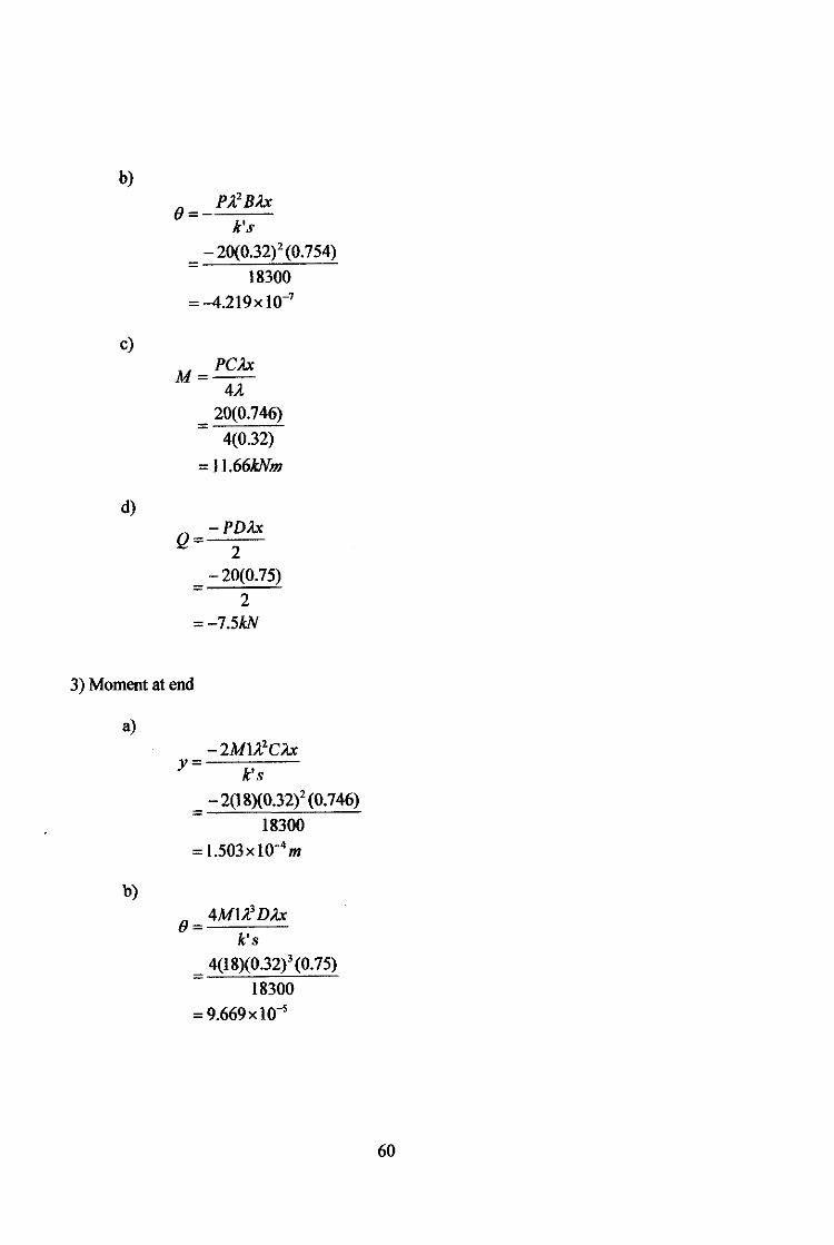
b)
c)
d)
(} = p ;.,2 B).x k's
- 20(0.32)2 (0. 754) =
18300
= -4.219x Io-'
M = PC).x
=
4J. 20(0.746)
4(0.32)
=11.66kNm
-PDA.x Q=--
2 -20(0.75)
= 2 =-7.5kN
3) Moment at end
a)
b)
-2MU2 CA.x y=
k's
- 2(18)(0.32/ (0.746) =
18300
= 1.503x Io-•m
(} = 4MU3 DA.x
k's 4(18)(0.32)3 (0. 75)
= 18300
=9.669xlo-•
60
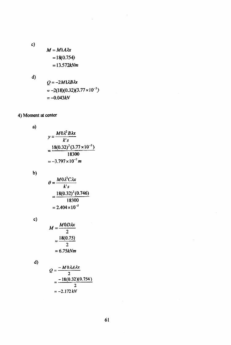
c)
d)
M=M1AA.x
=18(0.754)
= 13.57'2kNm
Q = -2M1A.BA.x
= -2(18)(0.32){3.77 X ]0-3)
=-0.043kN
4) Moment at center
a)
b)
c)
d)
y
}8(0.32)2 (3.77 X 10⁻³)
18300
=-3.797xl0-7 m
k's 18(0.32)3 (0. 746)
18300
= 2.404xlo-s
M MODA.x 2
18(0.75) =
2 =6.75kNm
Q -MOA.AI1x 2
-18(0.32X0.754) =
2 = -2.172/rN
61