development of a two-dimensional internal combustion ... · pdf fileengine has been developed...
TRANSCRIPT
Development of a two-dimensional internal combustion engines model using CFD for education purpose
Z.F. Tian a and J. Abraham a
a School of Mechanical Engineering,University of Adelaide.Adelaide, SA5005, Australia Email: [email protected]
Abstract: A two-dimensional (2D) computational fluid dynamics (CFD) model of a spark ignition (SI) engine has been developed using the commercial CFD package ANSYS/FLUENT 14.0. This model comprises one cycle of a 4-stroke engine, including intake stroke, compression stroke, power stroke and exhaust stroke. The combustion of the fuel, heptane, is included in this model. The inclusion of combustion helps students to better understand chemical reactions, species transport, and work and heat transfer in the engine. In addition to adding combustion, realistic boundary conditions are used in the current engine model.
The SI engine model has been implemented in a 2-hour CFD practical session in the Level IV undergraduate/postgraduate subject 'Automatic combustion' in the School of Mechanical Engineering at the University of Adelaide. This is the first time, to the best knowledge of the authors, that CFD has been used as a hands-on tool in internal combustion (IC) engine education. This paper presents some details of the engine model and some predicted results including temperature, velocity fields, species concentration and pressure profiles.
Keywords: Computational Fluid Dynamics (CFD), internal combustion engine, engineering education
20th International Congress on Modelling and Simulation, Adelaide, Australia, 1–6 December 2013 www.mssanz.org.au/modsim2013
1575
Tian and Abraham, development of 2-D combustion engine model for education
1. INTRODUCTION
Internal combustion (IC) engines are widely used to convert chemical energy of fuel into mechanical power in many engineering applications, e.g. road and off-road vehicles, locomotives, marine vehicles, airplanes, and in stationary applications such as electric power generation and gas pipelines (Heywood, 1988). Undergraduate level courses on IC engines are an integral part of the curriculum in many engineering programs. The effective pedagogy of IC engines within an integrated curriculum not only focus on the practical aspects of existing engine designs and their operation, but also on the application of the fundamentals of fluid mechanics, thermodynamics, and mechanics to the design of efficient and environmentally friendly engines of the future. In this context, computational tools are powerful means of communicating information to students visually and giving them the opportunity to explore a multivariate parametric space.
There has been prior work on the use of modelling and simulation tools such as IC performance software and thermodynamic software to enhance the teaching and learning of IC engines in undergraduate courses for engineering students, e.g. (Kirkpatrick & Willson, 1998; McGregor, Fraze, Baker, Drueckhammer, & Lawver, 2003; McGregor, Griffeth, Wheat, & Byrd, 2004; Zueco, 2011). These modelling and simulation tools developed to date focus on either simple cycle analysis or the overall performance of IC engines. They do not, however, provide detailed insights into the physical and chemical phenomena within the engine combustion chambers (also called cylinders). The processes in the cylinders in IC engines are generally complex and include many physical and chemical mechanisms, namely, turbulent flows, heat conduction, convection and radiation, multiphase flows, and chemical reactions. These processes occur at great speeds, making it hard for the students to understand them intuitively and perceive the importance of the coupling effects between them (McGregor et al., 2003). Understanding and appreciating the complexities of the internal processes can add a valuable element into the learning experience especially when the fluid fields are displayed by employing visualization software.
In this study, a more comprehensive and advanced modelling approach employing computational fluid dynamics (CFD) software, which numerically solves the transport equations for multiphase fluid flows in the engine cylinder and ports, is implemented in an undergraduate course on IC engines to enhance the pedagogical experience. CFD has been extensively used as a research and development tool for IC engines for over 30 years, in academia and in the automotive industry, as reflected in thousands of papers which appear in the automotive literature e.g.(Bracco, 1975; Gosman, 1985; Hou & Abraham, 1995). However, to the best knowledge of the authors, however, no report has been found in literature on the application of CFD techniques as a hands-on tool in teaching IC engines, though CFD is already being used as a teaching tool in some other engineering subjects at undergraduate and postgraduate levels.
In this study, the authors have developed a two-dimensional (2D) planar model of a spark ignition (SI) engine cylinder based on the widely used industrial CFD code ANSYS/FLUENT 14.0. More detailed descriptions of the SI engine model are given in Section 2. This CFD model is then implemented in a 2-hour practical session in an undergraduate/postgraduate course ‘Automotive combustion’ at the University of Adelaide. The aims of the implementation of the SI engine model in the course are to enable students to keep up with the state-of-the-art modelling tool and gain hands-on experience with the tool. Also, by running this CFD model, students can visualise and understand the physical and chemical processes in engine cylinders, including the piston and valve motions, combustion, species transport, flow patterns, temperature distribution, and particularly the coupling effects of these processes.
2. MODEL OF THE SI ENGINE
The authors have developed an SI engine model, using the 2D geometry and mesh of a tutorial ‘Cold Flow Simulation inside an SI engine’ that was available in FLUENT versions 6.3, to simulate combustion using the latest FLUENT version ANSYS/FLUENT 14.0. The ‘cold flow case’ tutorial, previously available in FLUENT 6.3, only included flow of air and fuel droplets into the engine, but not the combustion. The inclusion of combustion helps students to better understand chemical reactions, species transport, and work and heat transfer in the engine. In addition to adding combustion, more realistic boundary conditions are used in the current engine model.
During the CFD practical session, students run the model for a 4-stroke cycle, i.e. two rotations of the crank-shaft. Each rotation corresponds to 360o of crank angle (CA), i.e. two strokes. The four strokes correspond to intake, compression, power, and exhaust strokes. In the discussion that follows, the modelling process starts at 360.5° CA, corresponding to physical time of 0 s, that is 0.5°CA after the top dead centre (TDC). 360° CA is assumed to be the start of the intake stroke. The run completes at 1080.5°CA (physical time 0.06 s) that is
1576
Tian and Abraham, development of 2-D combustion engine model for education
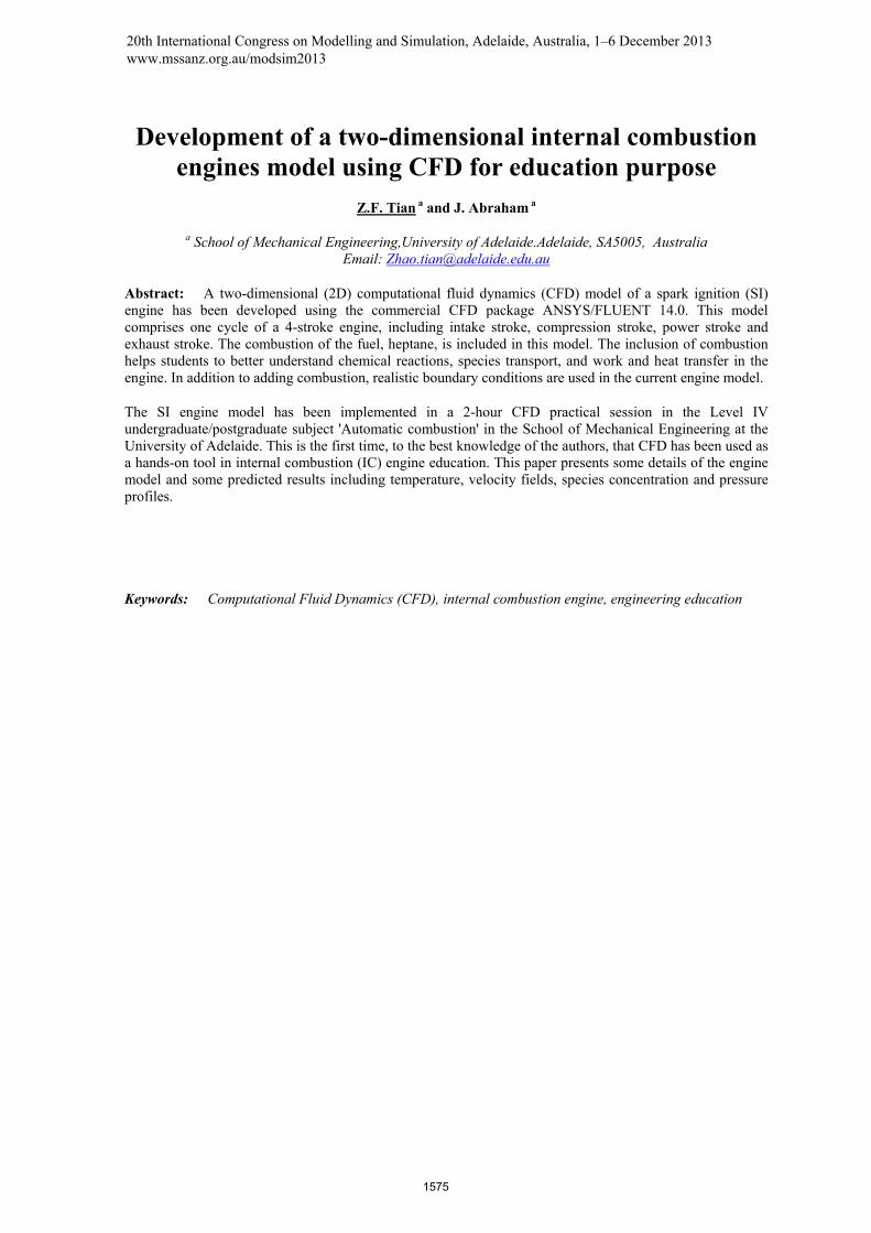
0.5° after top dead centre (TDC), i.e. the starting point of the engine cycle in the simulation. Figure 1 shows the geometry and mesh of the SI engine model at 378.5°CA degrees. This SI engine model is composed of the intake port and valve, exhaust port and valve, the combustion cylinder and the piston surface. The inner diameter of the cylinder is 0.15 m and the stroke is 0.09 m. The speed of the piston is 2000 revolutions per minutes (rpm). The fluid domain is divided into several mesh zones. Quadrilateral dynamic meshes are used in zones above the valves and in the cylinder where the piston sweeps through during the cycle.
Figure 1 the mesh of the SI model at Crank angle of 378.5 degree.
Heptane (C7H16) is used as the fuel. The injection of the heptane begins at 420°CA and ends at 493oCA during the intake stroke. A discrete particle model is used to calculate droplet trajectories. In the CFD model, the heptane droplets are injected through four streams in the intake port area. The mass flow rate of heptane is set as 0.011748 kg/s and the equivalence ratio is close to 1. The droplets injected have the uniform initial size of 25 µm.
After entering the cylinder, heptane droplets vaporize as a result of heat transfer from the high temperature residual combustion gas. The heptane vapour mixes with the air in the combustion cylinder. The mixture is ignited at 700.5°CA. The spark plug is not included in the CFD model. Instead, the spark event is modelled by the Fixed Spark Size model available in ANSYS/FLUENT 14.0. In the CFD model, the combustion process of heptane is reduced to a single step irreversible reaction,
C7H16+11(O2+3.76N2)→7CO2+8H2O+41.36 N2 (1)
The turbulence in the flow is modelled by the standard k-ε model. The turbulent dispersion of the droplets is considered by using a discrete random walk model as the effects of turbulence on droplet trajectories are not negligible. The combustion process is calculated by the species transport equations with volumetric reactions. The eddy-dissipation model (Magnussen & Hjertager, 1977) is used for the turbulence-chemistry interactions; the assumption is that when the hot products and the fuel/air mixture (the reactants) mix at the molecular level, the fuel/air mixture is converted to products.. The eddy-dissipation model determines the rate at which this mixing occurs, i.e. the rate at which the heat from the products diffuses into the reactants.
The CFD model is based on the Pressure Implicit with Splitting of Operators (PISO) (Issa, 1986) algorithm for the pressure-velocity coupling. The PISO algorithm is found to be efficient and fast in solving many unsteady problems. The first order upwind differencing scheme is used for the momentum, energy, species and turbulence equations.
Piston surfac
Exhaust valve
Combustion cylinder
Intake valve
1577
Tian and Abraham, development of 2-D combustion engine model for education
3. DISCUSSIONS OF CFD RESULTS
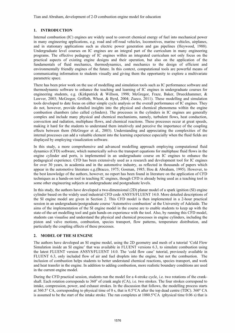
Figures 2a -2c show the simulated droplets in the cylinder at 432.5°, 519.5°, and 648.5°CA, respectively. The droplets in Figure 2 a-c are colored by droplet diameters. The injection of the fuel begins at 420°CA. At 432.5°CA as shown in Figure 2a, the droplet diameters have not changed significantly, since the intake air is at a low temperature of 90°C. The droplets are then heated by the residual gas in the cylinder and evaporate. As shown in Figure 2b, the diameters of droplets reduce significantly by the time they reach the region above the piston. At 648.5°CA (Figure 2c), most droplets have evaporated. This can explain the high concentration of heptane vapour found in the region above the piston (shown in Figure 2d).
Figure 2 (a-c) the simulated droplets in the cylinder at different crank angles, (d) the simulated heptanes concentration at 638.5°CA.
(a) (b)
(c) (d)
1578
Tian and Abraham, development of 2-D combustion engine model for education
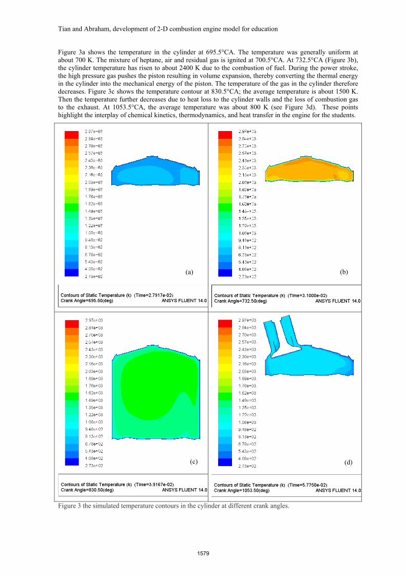
Figure 3a shows the temperature in the cylinder at 695.5°CA. The temperature was generally uniform at about 700 K. The mixture of heptane, air and residual gas is ignited at 700.5°CA. At 732.5°CA (Figure 3b), the cylinder temperature has risen to about 2400 K due to the combustion of fuel. During the power stroke, the high pressure gas pushes the piston resulting in volume expansion, thereby converting the thermal energy in the cylinder into the mechanical energy of the piston. The temperature of the gas in the cylinder therefore decreases. Figure 3c shows the temperature contour at 830.5°CA; the average temperature is about 1500 K. Then the temperature further decreases due to heat loss to the cylinder walls and the loss of combustion gas to the exhaust. At 1053.5°CA, the average temperature was about 800 K (see Figure 3d). These points highlight the interplay of chemical kinetics, thermodynamics, and heat transfer in the engine for the students.
Figure 3 the simulated temperature contours in the cylinder at different crank angles.
(a) (b)
(c) (d)
1579
Tian and Abraham, development of 2-D combustion engine model for education
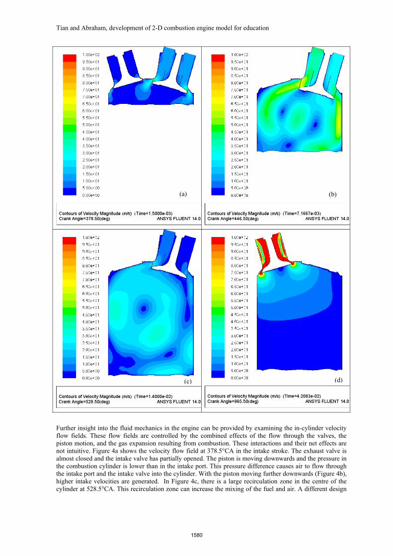
Further insight into the fluid mechanics in the engine can be provided by examining the in-cylinder velocity flow fields. These flow fields are controlled by the combined effects of the flow through the valves, the piston motion, and the gas expansion resulting from combustion. These interactions and their net effects are not intuitive. Figure 4a shows the velocity flow field at 378.5°CA in the intake stroke. The exhaust valve is almost closed and the intake valve has partially opened. The piston is moving downwards and the pressure in the combustion cylinder is lower than in the intake port. This pressure difference causes air to flow through the intake port and the intake valve into the cylinder. With the piston moving further downwards (Figure 4b), higher intake velocities are generated. In Figure 4c, there is a large recirculation zone in the centre of the cylinder at 528.5°CA. This recirculation zone can increase the mixing of the fuel and air. A different design
(a) (b)
(c) (d)
1580
Tian and Abraham, development of 2-D combustion engine model for education
of the valve can change the flow pattern, thereby changing the mixing patterns and thermal efficiency. During the exhaust stroke, when the exhaust valve is open, the product gas in the cylinder flow out through the exhaust port. As the pressure in the cylinder is much higher than the ambient pressure, the velocities in the exhaust port (Figure 4d) are much higher than the velocities in the intake port during the intake stroke (Figure 4a).
In addition to these instantaneous results, students can view the cylinder-averaged CFD results such as the volume-average temperature and the volume-average pressure as a function of time. However, due to the limited space, these results are not given in the paper.
4. CONCLUSIONS AND FUTURE WORK
A 2D CFD model of a four-stroke SI engine has been developed using the commercial CFD package ANSYS/FLUENT 14.0. The combustion of the fuel, heptane, is included in this model. The model can predict detailed velocity field, fuel droplets trajectories, temperature distribution and species concentration in the engine cylinder for four strokes.
The SI engine model has been implemented in a 2-hour CFD practical session in the Level IV undergraduate/postgraduate subject 'Automatic combustion' in the School of Mechanical Engineering at the University of Adelaide. From a larger perspective, the use of advanced CFD modelling tools helps students better understand the combined effects of chemical reactions, species transport, flow patterns, and temperature distributions in the SI engine. These effects relate to phenomena that the students have studied in other fundamental subjects in the curriculum, e.g. fluid mechanics, heat transfer, and thermodynamics. As such the relationships between fundamentals studied in diverse subjects and their importance in engineering design are emphasized. CFD is a powerful tool to achieve this goal. To generate results in a reasonable amount of time, however, compromises have to be made in the numerical and physical aspects of the problem. It is important to point out the consequences of such compromises to the students and still in the students the need for critical evaluation of CFD results.
ACKNOWLEDGEMENTS
The first author would like to thank Dr John Willison in the School of Education at the University of Adelaide for his suggestions and discussions.
REFERENCES
Bracco, F. V. (1975). Introducing a new generation of more detailed and informative combustion models. Gosman, A. D. (1985). Multi-dimensional modelling of cold flows and turbulence in reciprocating engines. Heywood, J. B. (1988). Internal combustion engine fundamentals: McGraw-Hill, New York. Hou, Z., & Abraham, J. (1995). Three-dimensional modelling of soot and NO in a direct-injection diesel
engine, . Issa, R. I. (1986). Solution of the implicitly discretised fluid flow equations by operator-splitting. Journal of
computational physics, 62(1), 40-65. Kirkpatrick, A., & Willson, B. (1998). Computation and experimentation on the Web with application to
internal combustion engines. Journal of Engineering Education-Washington-, 87, 529-538. Magnussen, B. F., & Hjertager, B. H. (1977). On mathematical modeling of turbulent combustion with
special emphasis on soot formation and combustion. Paper presented at the Symposium (International) on Combustion.
McGregor, K. W., Fraze, S., Baker, M., Drueckhammer, D., & Lawver, D. (2003). Effects of computer animated instruction upon low-level cognition of undergraduates in an agricultural power technology course. Paper presented at the Proceedings of the 22nd Annual Western Region Agricultural Education Research Conference, Portland, Oregon, 23,(No Page Numbers Available).
McGregor, K. W., Griffeth, S. L., Wheat, T. L., & Byrd, J. (2004). Using computer-generated animation as additional visual elaboration in undergraduate courses-student perceptions. Paper presented at the the 23rd Annual Western Region Agricultural Education Research Conference, Honolulu, Hawaii.
Zueco, J. (2011). Educational software to study alternative internal combustion engine cycles. International Journal of Mechanical Engineering Education, 39(2), 101-113.
1581