development and manufacture of dies for car body production
TRANSCRIPT
Keynote Papers
Development and Manufacture of Dies for Car Body Production
Klaus Siegert, Stuttgart, Germany (2) T. Altan, Columbus, OH, USA (1) T. Nakagawa, Tokyo, Japan (1)
Abstract
The costs for development and production of draw dies for car outer panels are extremely high and should be reduced.
Furthermore it is necessary to reduce the time for developing, designing and producing the dies for the production of
parts. This paper discussed new press techniques, die designs and milling techniques. The trend goes to single acting
presses with CNCcontrolled multipoint cushion systems in the press table and to special designed dies. These systems
lead to a more robust and reproduable forming process with improved product qualtty.
Kevwords: Deep Drawing, Cushion System, Binder Design
Press shop people ask for more robust ,sheet metal
forming processes and hope the designers will come up
with stamping geometries that are easier to form.
We can certainly expect that efforts will be made to
design parts with easier to form contours. Nevertheless,
the automotive and stamping industries will continue to
work towards achieving the following objectives:
0 Introducing aluminum sheet metal
0 Increasing the use of'HSLA-steel with higher yield
strength
0 Increasing the use of zinc coated steel
0 Reducing the number of parts per car
0 Reducing the number of dies per part
0 Production of parts with zero defects
0 Production of outer panels with excellent surface, so
that no handwork is needed in the body in white shop
0 Reduction of the production costs
In the USA a so called 'Near Zero Stamping' - program
is conducted for achieving precision and agility in sheet
metal stamping. This program is camed out jointly by
twenty-two Auto Body Consortium companies in
cooperation with Chrysler, Ford and General Motors and
We research institutions.
The objectives of the 'Near Zero Stamping' program is
to improve the accuracy of stamped sheet metal parts
and to reduce the time currently required for sheet metal
die design, try out and production. This is only an
Annals of the ClRP Vol. 46/2/1997
example that shows the need for improvements in the
press shop.
These goals are not only important in the USA, but they
are important for every press shop in the world.
Furthermore we have to realize that the time from
developing and designing the die to the first production
of parts will be reduced from about 18 months to 12
months. We must also remember that stamping dies
needed to produce one passenger car costs between
200 and 300 million dollars and that a press shop for the
produdion of all the sheet metal parts for about 1000
cars per day costs about $ 500 million. Thus, the
investments in press shops are very high. Thus, it is
worthwhile to make significant improvements in the
press shop. In the future the problems associated with
stamping will increase and not decrease because of ever
increasing demands of the automotive industry.
In this paper the present situation, future trends and the
goals for development and manufacture of dies for car
body production are discussed.
In doing this the focus is on draw dies.
3. Draw Process
Drawing sheet metal parts for the autobody is in principle
a combination of deep drawing and stretch forming.
During the drawing of non-axisymmetric sheet metal
parts, the flow of the material between upper and lower
binder should be controlled, so that neither wrinkles nor
tears appear in the drawn part.
To control the material flow between the binders one or
a combination of the following possibilities can be used:
535
a0 Shape of the blank Larger blanks lead to higher
deformation- and frictional-forces which hinder
material flow. Smaller blank sizes favour the material
flow.
bO Draw beads: Both friction- and bending-forces
induced by draw beads provide a hindrance to the
material flow.
c 0 Lockbeads: They prevent the material flow between
the binder surfaces entirely.
dOFriction between the upper binder and the sheet
metal and between the sheet metal and the lower
binder. Higher friction can hinder the material now,
lower friction can favour the material flow.
The friction can be influenced by
the type of lubricant and the amount of lubrication
adjusting the gap between the upper and lower
binder. A larger gap results in less pressure and less
friction, a smaller gap results in higher pressure and
more friction.
last but not least, the friction that can be influenced
by elastic deformation of the blankholder (This is the
upper binder of dies for double action presses and
the lower binder of dies for single action presses with
a cushion system in the press table) deformed by the
blankholder forces.
3. Realization of the Blankholder Forces
3.1 Double Action Press with a 818nkholder Ram
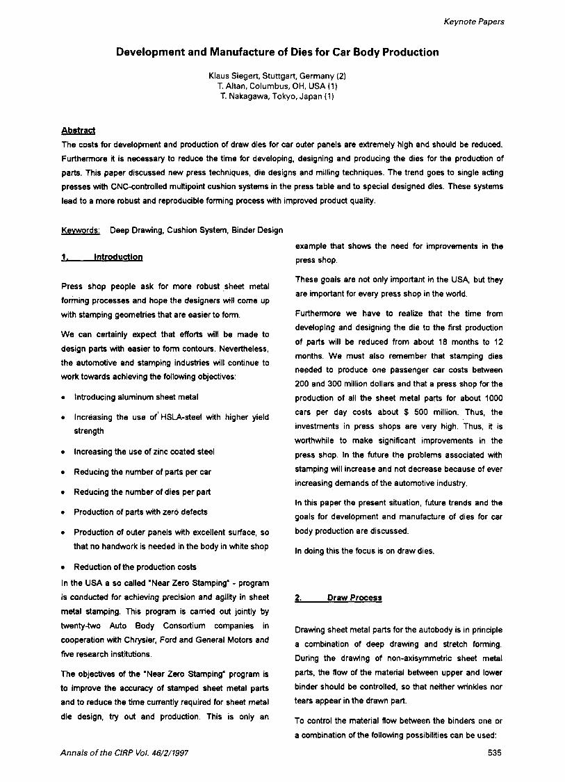
Fig. 1 left, shows a draw die for a double action press.
These presses have the possibility to adjust the
blankholder forces at four pressure points of the
blankholder ram. It is possible to adjust constant binder
forces over the stroke differently for "front left", "front
right", "rear left" and "rear right" (2), (4).
For mechanical presses normally the blankholder forces
is constant over the stroke at each of the four points. For
double acting mechanical presses the possibility to run
at each pressure point different force cuwes over the
stroke, is still in the developmental stage (5). This is
easy to achieve in a hydraulic double action press.
w m , -*dnm,r.~- --p-d.nlbwlo ( h r Q n M a h m s h . r W D m C u d h ~ h * . h r M
0
h
aJ Rmn d ) u R y 1 6 0) QI.lia h s n n r a r w c r * a n w b ) l H h d d r R m e ) L o r h d u h J C U l k n C W #J Amh 3h.r-
Fig.1: Draw dies in double action presses and in single
action presses with cushion systems in the press
table.
3.2 Single Action P m with a Pneumatic Cushion System in the Press Table
To control the material flow by deforming the blankholder
elastically the following must be considered:
Fig. 1 middle. s h o k the draw die for a single acting
press. In this type of mechanical hydraulical press the
female die is clamped to the ram and the male die is - the manner in which the load is applied from the
press to the die
- the elastic behavior of the die positioned on the press table. The blankholder is the
lower binder. It is supported by a cushion system in the
- the distance between the upper and the lower binder. press table or by nitrogen cylinder systems in the dies
(9).
Thus the blankholder forces are introduced to the lower
binder (blankholder) by nitrogen cylinders in the die or by
a cushion system in the press table. Most of the
536
Keynote Papers
presently used cushion systems are pneumatic systems.
Here a number of cushion pins are positioned between
the lower binder and a cushion plate which is supported
by a pneumatic cylinder.
The blankholder force is introduced to the lower binder
by the cushion pins when the ram (upper die) forces the
lower binder downwards with the force of the cushion
system. The total cushion force is given by the
pneumatic pressure multiplied with the cross sectional
areas of the pneumatic cylinders (9).
There are a number of disadvantages of the pneumatic
cushion system:
High peak load on the blankholder at the moment when the upper binder contacts the blank on the
lower binder
Dependence of the blankholder force on the number
of strokes per minute
The cushion plate tips by eccentric loading
The cushion pins, after some time, have slightly
different heights because of to high localized
pressure. This effects the elastic deflection of the
binder.
As a result of all these disadvantages, the pneumatic
cushion does not provide a reproducable forming
process. Furthermore it should be noted that pneumatic
or hydraulic central cylinders do not allow to adjust the
force at the corner points of the blankholder, as it is
possible with a double action press.
3.2 Single Action Presses with a Hydraulic 4 Point Cushion System in the Press Table
during the stroke for each cylinder separately by servo or
proportional valves.
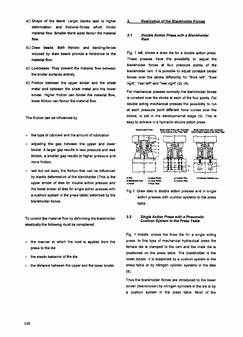
When the upper binder, which is attaches to the ram,
contacts the blank placed on the lower binder a pressure
peak occurs on the blankholder force. This peak can be
reduced by appropriate programming of the hydraulic
cylinders, Figure 2 (2).
The pressure peak caused by contacting the blank on
the lower binder by the upper binder which is fixed to the
ram can be reduced below the level of the constant
blankholder force by programming an ascending ramp
(Fig. 2) (2).
I !
Fig. 2: Reduction of the pressure peak by programming
an ascending ramp.
The direct support of the blankholder by 4 hydraulic
cylinders in the comer points results in a well defined
method of the blankholderforce-transmission. It allows
the control the force of every cylinder induvidually during
the stroke. It was shown in practice and by experimental
investigations that mechanical single action presses with
hydraulic 4-point cushion systems in the press table give
better and 'reproducible draw results than mechanical
double action presses.
A big step forward was made by the development of a We can state that:
hydraulic four comer point cushion system. This is seen
in Fig. 1 right (4), (8) ,Mechanical single action presses with an excellent.
hydraulic cushion system are preferable to This system is mainly a passive hydraulic system
because the pressure in the 4 cylinders increases by
compression when the lower binder is forced
downwards. So it is possible to control the pressure
mechanical double action presses."
537
3.3 Single Action Press with Multipoint Cushion System in the Res8 Table
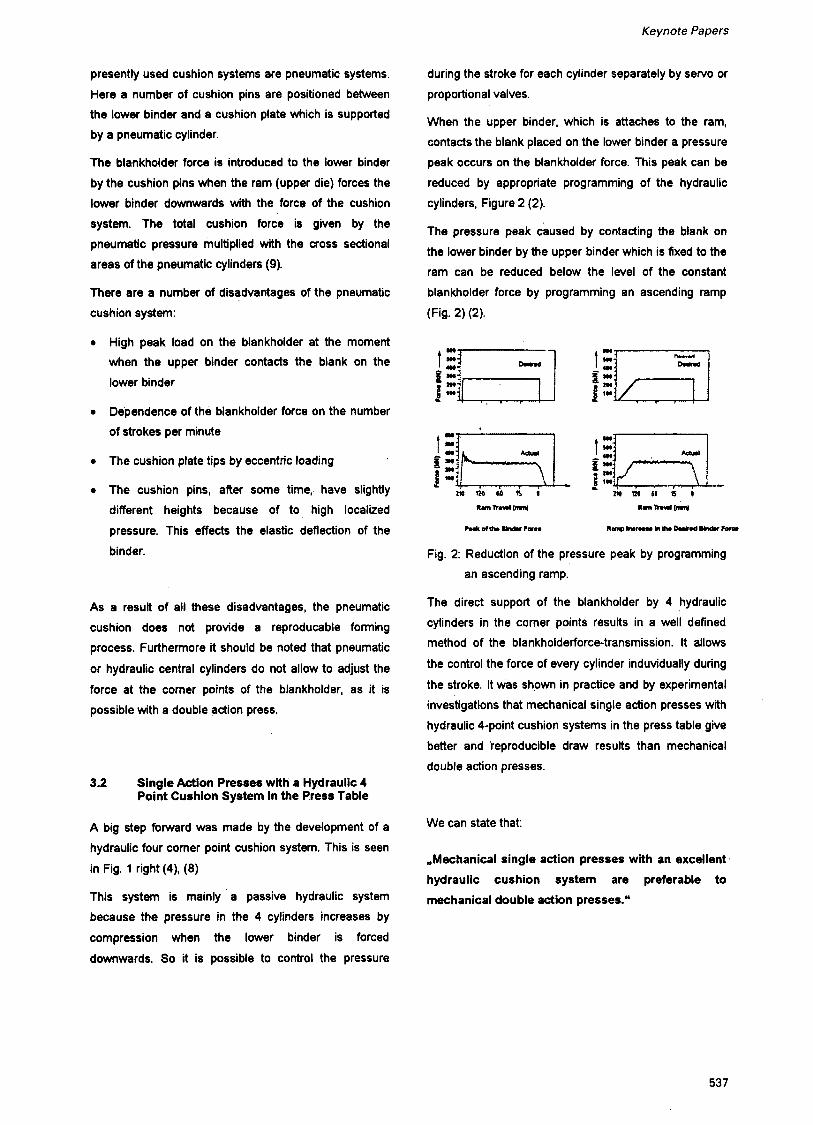
The direct support of the lower binder by 4 hydraulic
cylinders seems to be excellent for dies up to 1OOOmm x
1000mm. Larger dies have to be supported by more
than 4 hydraulic cylinders (Fig. 3). If every cylinder has
its own sew0 valve it is possible to control the pressure
between the binders and the blank in certain areas by
corresponding hydraulic cylinders (9).
F i g 3 Multipoint cushion system.
A further possibility to build up muttipoint cushion
systems is shown in Fig. 4. This system supports the
cushion plate by' four hydraulic cylinders that are
individually CNC controllable and height adjustable
during the stroke by servo valves (1 0).
Fig.4: Multipoint cushion system with 10 pins.
CNC-height-adjustable cushion pins with load cells are
pressed against the cushion plate and transfer the
blankholder forces to the lower binder. The blankholder
forces can be adjusted for every pin by adjusting the pin
height. The measurement of the axial force on each
cushion pin allows a programmable and reproducible
adjustment of the active cushion pins. Thus it is possible
to program a reproducible adjustment of the elastic
binder deflection which affects the pressures and friction
forces between the binder and the blank (10).
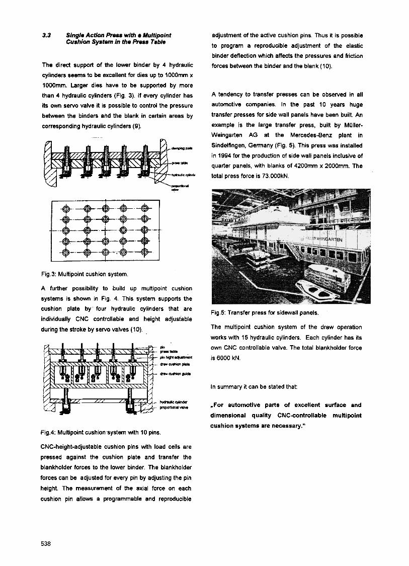
A tendency to transfer presses can be observed in all automotive companies. In the past 10 years huge
transfer presses for side wall panels have been built. An
example is the large transfer press, built by MClller-
Weingarten AG at the Mercedes-Benz plant in
Sindelfingen, Germany (Fig. 5). This press was installed
in 1994 for the production of side wall panels inclusive of
quarter panels, with blanks of 4200mm x 2000mm. The
total press force is 73.000kN.
Fig.5: Transfer press for sidewall panels.
The multipoint cushion system of the draw operation
works with 15 hydraulic cylinders. Each cylinder has its
own CNC controllable valve. The total blankholder force
is 6000 kN.
In summary it can be stated that:
,For automotive parts of excellent surface and
dimensional quality CNCcontrollable multipoint
cushion systems are necessary."
538
Keynote Papers
4. Draw Die%
Normally the dies are produced as 'rigif and not as
flexible dies. But we have to consider that a die can not
be entirely rigid. It will be elastically deformed by the
process forces. So it is necessary to spotin the distance
between upper and lower binder due to the elastic
behavior of the die and of the press.
This results in a specific blankholder pressure
distribution between upper binder, blank and lower
binder of a draw die in a given press.
When using a CNC-controllable multipoint cushion
system it is possible to influence by each cushion pin a
corresponding defined area of the lower binder surface.
Conventionally designed dies have ribs so located that
the die is relatively .rigi&.
But these rigid dies deflect under the blankholder forces.
Fig. 6 show for a rectangular pan the pressure between
lower binder, blank and upper binder when all pin forces
are equal (4).
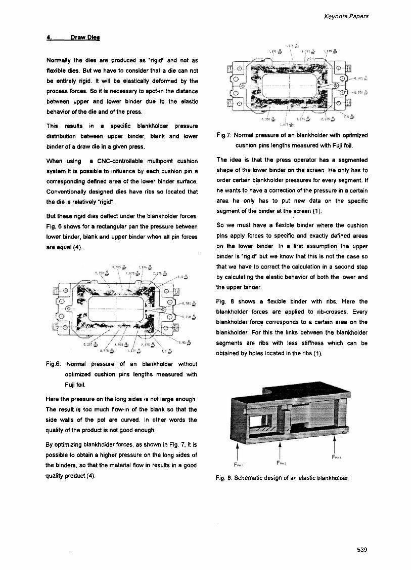
Fig.7: Normal pressure of an blankholder with optimized
cushion pins lengths measured with Fuji foil.
The idea is that the press operator has a segmented
shape of the lower binder on the screen. He only has to
order certain blankholder pressures for every segment. If
he wants to have a correction of the pressure in a certain
area he only has to put new data on the specific
segment of the binder at the screen (1).
So we must have a flexible binder where the cushion
pins apply forces to specific and exactly defined areas
on the lower binder. In a first assumption the upper
binder is 'rigid' but we know that this is not the case so
that we have to correct the calculation in a second step
by calculating the elastic behavior of both the lower and
the upper binder.
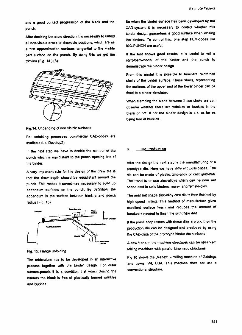
Fig. 8 shows a flexible binder with ribs. Here the
blankholder forces are applied to ribcrosses. Every
blankholder force corresponds to a certain area on the
blankholder. For this the links between the blankholder
segments are ribs with less stiffness which can be
obtained by hples located in the ribs (1).
Fig.6: Normal pressure of an blankholder without
optimized cushion pins lengths measured with
Fuji foil.
Here the pressure on the long sides is not large enough.
The result is too much flow-in of the Mank so that the
side walls of the pot are curved. In other words the
quality of the product is not good enough.
By optimizing blankholder forces, as shown in Fig. 7, it is
possible to obtain a higher pressure on the long sides of
the binders, so that the material flow in results in a good
quality product (4). Fig. 8: Schematic design of an elastic blankholder.
539
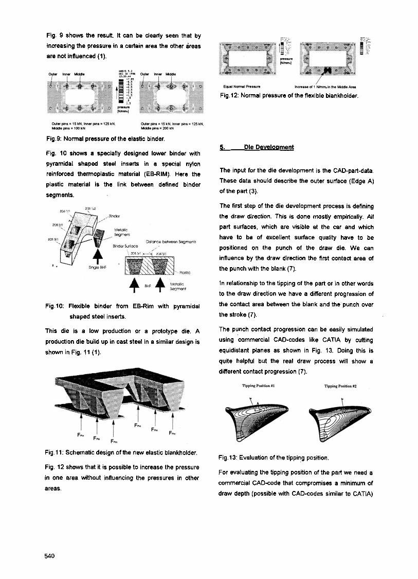
Fig. 9 shows the result. It can be clearly seen that by
increasing the pressure in a certain area the other areas
are not influenced (1).
Fig.12: Normal pressure of the flexible blankholder.
Fig.9: Normal pressure of the elastic binder.
Fig. 10 shows a specially designed lower binder with
pyramidal shaped steel inserts in a special nylon
reinforced thermoplastic material (EB-RIM). Here the
plastic material is the link between defined binder
segments.
Fig.10: Flexible binder from EB-Rim with pyramidal
shaped steel inserts.
This die is a low production or a prototype die. A
production die build up in cast steel in a similar design is
shown in Fig. 11 (1).
5. Die DeveloDment
The input for the die development is the CAD-part-data.
These data should describe the outer surface (Edge A)
of the part (3).
The first step of the die development process is defining
the draw direction. This is done mostly empirically. All
part surfaces, which are visible at the car and which
have to be of excellent surface quality have to be
positioned on the punch of the draw die. We can
influence by the draw direction the first contact area of
the punch with the blank (7).
In relationship to the tipping of the part or in other words
to the draw direction we have a different progression of
the contact area between the blank and the punch over
the stroke (7).
The punch contact progression can be easily simulated
using 'commercial CAD-codes like CATIA by cutting
equidistant planes as shown in Fig. 13. Doing this is
quite helpful but the real draw process will show a
different contact progression (7).
Fig.11: Schematic design of the new elastic blankholder.
Fig. 12 shows that it is possible to increase the pressure
in one area without influencing the pressures in other
areas.
Fig.13: Evaluation of the tipping position.
For evaluating the tipping position of the part we need a
commercial CADcode that compromises a minimum of
draw depth (possible with CAD-codes similar to CATIA)
540
Keynote Papers
and a good contact progression of the blank and the
punch.
After deciding the draw direction it is necessary to unfold
all non-visible areas to drawable positions, which are as
a first approximation surfaces tangential to the visible
part surface on the punch. By doing this we get the
trimline (Fig. 14 ) (3).
Fig.14: Unbending of non visible surfaces.
For unfolding processes commercial CAPcodes are
available (i.e. Develop2).
In the next step we have to decide' the contour of the
punch which is equidistant to the punch opening line of
the binder.
A very important rule for the design of the draw die is
that the draw depth should be equidistant around the
punch. This makes it sometimes necessary to build up
addendum surfaces on the punch. By definition, the
addendum is the surface between trimline and punch
radius (Fig. 15).
-am
Fig. 15: Flange unfolding.
The addendum has to be developed in an interactive
process together with the binder design. For outer
surface-panels it is a condition that when dosing the
binders the blank is free of plastically formed wrinkles
and buckles.
So when the binder surface has been developed by the
CAD-system it is necessary to control whether this
binder design guarantees a good surface when closing
the binders. To control this, one step FEMcodes like
ISO-PUNCH are useful.
If the test shows good results, it is useful to mill a
styrofoamrnodel of the binder and the punch to
demonstrate the binder design.
From this model it is possible to laminate reinforced
shells of the binder surface. These shells, representing
the surfaces of the upper and of the lower binder can be
fixed to a binder-simulator.
When clamping the blank between these shells we can
observe weather there are wrinkles or buckles in the
blank or n d If not the binder design is 0.k. as far as
being free of buckles.
6. Die Production
After the design the next step is the manufacturing of a
prototype die. Here we have different possibilities. The
die can be made of plastic, zinc-alloy or cast gray-iron.
The trend is to use zinc-alloys which can be near net
shape cast to solid binders, male- and female-dies.
The near net shape zinc-alloy cast die is then finished by high speed milling. This method of manufacture gives
excellent surface finish and reduces the amount of
handwork needed to finish the prototype dies.
If the press shop results with these dies are o.k then the
production die can be designed and produced by using
the CAD-data of the prototype binder die surfaces.
A new trend in the machine structures can be observed:
Milling machines with parallel kinematic structures.
Fig 16 shows the ,Variaf .- milling machine of Giddings
and Lewis, WI, USA. This machine does not use a
conventional structure.
541
7- Conclusions
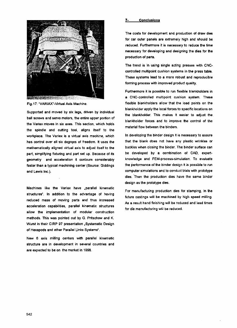
Fig.17: "VARIM-Virtual Axis Machine.
Supported and moved by six legs, driven by individual
ball screws and servo motors, the entire upper portion of
the Variax m'oves in six axes. This section, which holds
the spindle and cutting tool, aligns itself to the
workpiece. The Variax is a virtual axis machine, which
has control over all six degrqes of freedom. It uses the
mathematically aligned virtual axis to adjust itself to the
part, simplifying fixturing and part set up. Because of its
geometry and acceleration it contours considerably
faster than a typical machining center (Source: Giddings
and Lewis Inc.).
Machines like the Variax have .parallel kinematic
structures'. In addition to the advantage of having
reduced mass of moving parts and thus increased
acceleration capabilities, parallel kinematic structures
allow the implementation of modular construction
methods. This was pointed out by G. Pritschow and K Wurst in their ClRP 97 presentation .Systematic Design
of Hexapods and other Parallel Links Systems'.
The costs for development and production of draw dies
for car outer panels are extremely high and should be
reduced. Furthermore it is necessary to reduce the time
necessary for developing and designing the dies for the
production of parts.
The trend is in using single acting presses with CNC
controlled multipoint cushion systems in the press table.
These systems lead to a more robust and reproducible
forming process with improved product quality.
Furthermore it is possible to run flexible blankholders in
a CNC-controlled multipoint cushion system. These
flexible blankholders allow that the load points on the
blankholder apply the local forces to specific locations on
the blankholder. This makes it easier to adjust the
blankholder forces and to improve the control of the
material flow between the binders.
In developing the binder design it is necessary to assure
that the blank does not have any plastic wrinkles or
buckles when closing the binder. The binder surface can
be developed by a combination of CAD, expert-
knowledge and FEM-process-simulation. To evaluate
the performance of the binder design it is possible to run
computer simulations and to conduct trials with prototype
dies. 'Then the production dies have the same binder
design as the prototype dies.
For manufacturing production dies for stamping, in the
future castings will be machined by high speed milling.
As a result hand finishing will be reduced and lead times
for die manufacturing will be reduced.
New 6 axis milling centers with parallel kinematic
structure are in development in several countries and
are expected to be on the market in 1998.
542
Keynote Papers
References
(1) Hohnhaus, J., 1997, Blank Holder Designs using with (1 0) Siegert, K., 1991, Zieheinrichtungen a Multipoint Cushion System, Institute for Metali einfachwirkender Pressen for die Blechumformung.
Forming, Stuttgart , unpublished. DGM-Informationsgesellschaft, Oberursel.
(2) Klamser, M., 1992, Vielpunkt-Zieheinrichtungen als
Voraussetzungen far einen reproduzierbaren
Umformprozea. In: Siegert, K (Hrsg.): Neuere
Entwicklungen in der Blechumformung, DGM-
Informationsgesellschaft, Oberursel, 321-41 7.
(3) Kienzle, S., 1993, Optimierungsverfahren fur die
Rahmenanlagen-Entwicklung von Ziehwerkzeugen, . Beitrage zur Umformtechnik, Nr. 1, DGM-lnformations-
gesellschaft, Oberursel.
(4) Klamser, M., 1994, Ziehen von Blechteilen auf
einfachwirkenden Pressen mit hydraulischer
Zieheinrichtung im Pressentisch. BeitrAge zur
Umformtechnik, Nr.5, DGM-Informationsgesellschaft,
Oberursel.
(5) Klose, L, Braunlich, H.:, 1996, Vergleichende
Untersuchungen zur Mehrpunktziehtechnik. Blech Rohre
Profile 10, S. 512-514
(7) Roll, K., Harthun, S., 1996, Rechnergestutzte
Ziehrahmenkonstruktion. In: Siegert, K. (Hrsg.): Neuere
Entwicklungen in der Blechumfomung. DGM-
Informationsgesellschaft, Oberursel, S. 287-298.
181 Schneider, F. Steuerung des Kraft-Weg-Verlaufs
beim Umformen, dargestellt an der Ziehstufe einer
Groateilstufenpresse. In: Doege, E. (Hrsg.): "Ziehtechnik
auf der Groateilstufenpresse". HFF-Bericht Nr. 11, 1987,
S. 99-1 14. Hann. Forschungsinst. f. Fertigungsfragen
e.V.
(9) Siegert, K., 1997, Advances and Trends in Sheet
Metal Forming Processes. SAE Technical Papers Series
970436.
543