developing the next generation cockpit display system
TRANSCRIPT
eveloping the Next Generation
isplay Syste
B.C. Read, I11 US Air Force, Wright Laboratory
The goal of advanced cockpit display systems is to present large amounts of information quickly and in an understandable format, enabling the aviator to improve mission performance. Wright Laboratory is developing a program to dramatically improve current display systems. Current front-line cockpit display systems utilize low-resolution analog video to present two-dimensional (2-D) images on many separate displays. The future cockpit will be capable of integrating large picture digital video with three-dimensional (3-D) and 2-D color images. This system will be capable of rendering icons, maps, and world-views. It will be compatible with head mounted displays and multiple large displays to improve war-planning and combat aviator situational awareness.
Wright Laboratory is developing this system in conjunction with Honeywell Technology Center. We are developing a massively parallel 3-D renderer which will be capable of updating 500,000 3-D triangles per second with shading, lighting, transparency, texture mapping, and hidden surface removal. The renderer design, based on a University of North Carolina pixel planes design, employs a massively parallel architecture with 1,024 ALUs per chip
Author’s Current Address: US Air Force, Wright Laboratory, Solid State Electronics Directorate, WLELED, Wright Patterson AFB, Ohio 45433-751 1.
Based on a piesentation at NAECON ’96; rev~sion received August 6, 1996.
0885-8985/96/$5.00 0 1996 lEEE
to display one million anti-aliased vectors per second. Current high end workstations are capable of these display goals, but fall far short of military reliability, size, and power requirements. The rendering system will be small enough to fit on one board, extensible to dual-seat configuration, and capable of up to eight windows per display channel.
[NTRODUCTION
Today more than ever, aviators are presented with a barrage of information. Victory in the air increasingly hinges on who can absorb data and utilize it effectively. ‘Toward this end, our warfighters require the fastest and most advanced cockpit displays we can p ~ ~ h c e with current technology. At the same time, the Air Force must acknowledge limited funds and embrace ideas such as employing Commercial Off The Shelf parts (COTS). This paper outlines a program to substantially improve today’s cockpit display capabilities with a high performance and cost effective mix of COTS parts and internally researched custom components.
Current front-line fighters display two-dimensional, monochromatic images on multiple displays driven by several different rendering sources and systems. The Panoramic Cockpit Control and Display System (PCCADS) 2000 study indicated that large, high resolution images can improve fighter pilots’ reaction time [l]. This is achieved by bringing the large number of disjointed displays and classic “steam gaugcs” into an integratcd, unified display environment using standard i ~ ~ o r ~ a ~ ~ o ~ formats such as common colors, icons, etc. This
IEEE AES Systems Magazine, October I996 25
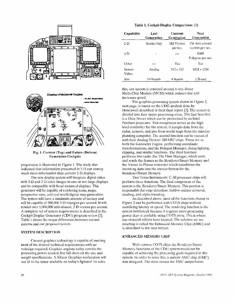
Table 1. Cockpit Display Comparisons La]
Capability Last Current Next Generation Generation ~ e n ~ r ~ ~ ~ o n
2-D Stroke Only 1M Vectors 1M Anti-aliased per sec. vectors per sec.
3-D _- ____ 500M Polygons per sec.
Color _- Yes Yes
Sensor Analog 512x512 1024x1280 Video Size 14 Boards 4 Boards 1 Board
Fig. 1. Current (Top) and Future (Bottom) Generation Cockpits
progression is illustrated in Figure 1. The study also indicated that information presented in 3-D can convey much more information than current 2-D displays.
with 3-D and 2-D color images in one or two large displays and be compatible with head mounted displays. This generator will be capable of rendering icons, maps, perspective view, and real world digital map generation. The system will have a minimum amount of latency and will be capable of 500,000 3-D triangles per second. It will render over 1,000,000 anti-aliased, 2-D vectors per second. A complete set of system requirements is described in the Cockpit Display Generator (CDG) program review [2]. Table 1 shows the major differences between current systems and our proposed system.
The new display system will integrate digital video
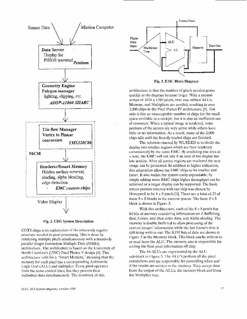
this, our system is centered around a very dense Multi-Chip Module (MCM) which reduces size and increases speed.
next page, is based on the CDG analysis done by Honeywell described in their final report [3]. The system is divided into four major processing areas. The first function is a Data Server which can be performed by an Intel Pentium processor. This component serves as the high level controller for the system; it accepts data from the radar, sensors, and also from world maps from the mission planning computer. The second function can be executed with four Analog Devices' SWARC chips. These act as both the Geometry Engine, performing coordinate transformations, and the Polygon Manager, doing lighting, clipping, and similar functions. The third function performs two tasks: the Tile Flow Manager, which sorts and sends the frames to the Renderer/Smart Memory and the Vertex to Planar converter which transforms the incoming data into the correct format for the Renderer/Smart Memory.
perform these functions. The final component of the system is the Rendererismart Memory. This portion is responsible for edge detection, hidden surface removal, shading, and alpha blending.
As described above, most of the functions shown in Figure 2 can be performed with COTS chips without sacrificing latency or speed. The rendering function is the system bottleneck because it requires more processing power than is available using COTS parts. This i s where our research efforts have focused. The solution we are enacting is called the Enhanced Memory Chip (EMC) and is described in the next section.
The graphics processing system shown in Figure 2,
Two Texas Instruments' C-80 processor chips will
SYSTEM DESCRIPTION ENHANCED MEMORY CHIP
Current graphics technology is capable of meeting most of the desired technical requirements with no redesign required. Graphics engines today contain the processing power needed, but fall short on the size and weight specifications. A Silicon Graphics workstation will not fit in the space available on today's fighters! To solve
With current COTS chips the Renderer/Smart Memory functions of the CDG system would not be capable of achieving the processing goals required in this system. In order to solve this, a custom ASIC chip (EMC) was designed. The main reason the EMC outperforms
26 IEEE AES Systems Magazine, October 1996
Mission Computer
------J:
Video Display
COTS chips is its exploitation of the inherently regular structurc needed in pixel processing. This is done by rendering multiple pixels simultaneously with a massively parallel Single Instruction Multiple Data (SIMD) architecture. The architecture is based on the University of North Carolina's (UNC) Pixel Planes V design [4]. This architecture calls for a "Smart Memory," meaning that the memory for each pixel has a corresponding Arithmetic Logic Unit (ALU) and multiplier. Every pixel o p e r a t a from the same control lines, but they process their individual data simultaneously. The drawback of this
IEEE A ES Sy.ytem.s Magazine, October 1996
architecture is that the number of pixels needed grows quickly as the displays become larger. With a normal screen of 1024 x 1280 pixels, over one million ALUs, Memory, and Multipliers are needed, resulting in over 2,000 chips in the Pixel Planes IV architecture [5]. Not only is this an unacceptable number of chips for the small space available in a cockpit, but it is also an inefficient use of resources. When a typical image is rendered, some portions of the screen are very active while others have little or no information. As a result, many of the 2,000 chips idle until the heavily loaded chips are finished.
The solution enacted by WLELED is to divide the display into smaller regions which are then rendered consecutively by the same EMC. By rendering one area at a time, the EMC will not idle if an area of the display has low activity. After all screen regions are rendered the next image can be processed. In addition to higher utilization, this adaptation allows the EMC chips to be smaller and faster. It also rnakes the system easily expandable; by simply adding more EMC chips higher throughput can be achieved or a larger display can be supported. The basic screen portion covered with our chip was chosen by Honeywell to be 8 x 8 pixels [3]. There are a total of 32 of these 8 x 8 blocks in the current system. The basic 8 x 8 block is shown in Figure 3.
64 bits of memory containing information on 2,-buffering, Red, Green, and Blue color data, and Alpha shading. The memory is double buffered to allow processing of the current images' information while the last frame's data is still being written out. The 8,192 bits of data are shown in Figure 3 as the Memory block. This block can be written to or read from the ALU. The memory also is responsible for writing the final pixel information off chip.
The 64 ALUs are represented by the ALU sub-block in Figure 3. The AEU's perform all the pixel calculations and are responsible for controlling when and if the results are written to the memory. They accept data from the output of the ALUs, the memory block and from the Multiplier tree.
With this architecture, each of the 8 x 8 pixels has
27
The final component of the design is the multiplier tree. This concept, developed by the UNC design team, greatly reduces the circuitry required in performing 64 bit serial multiplies. The original design requires 384 multiplier cells, but by implementing the multiplier tree it is reduced to 127 for an 8 x 8 block.
The entire EMC design was described and modeled in VHISC Hardware Description Language (VHDL) by in-house designers. The VHDL was simulated with realistic test vectors representing real-world data to insure the chip would perform correctly when fabricated. The same VHDL code was then synthesized to schematic format. The schematic format is a netlist of common Register Transfer Level (RTL) components that directly maps to the actual circuitry on the chips. This netlist was then automatically arranged for proper fabrication using a place and route tool. The result is a layout ready to be sent to a fabrication facility for silicon processing. This design flow is completely automated from the design description in VHDL to the final layout description. The reliance on tool automation drastically reduces the engineering cost associated with designing a new chip. This design environment allows testing at every stage of the design: the VHDL level, netlist level, and layout level. Also, by evaluating this design flow the design team at Wright Labs gains valuable experience in CAD tool use which can be applied to contracts and tool development programs.
SUMMARY
The Cockpit Display system described in this paper will greatly enhance the display capabilities of tomorrow’s fighters and meets the processing goals desired for the next generation of display systems. Improvements in cost, size, weight, and ruggedness over current commercial graphics workstations make the insertion of this technology into cockpits possible. The careful use of COTS chips in this design will result in cost savings to the
Air Force and insure future growth as revisions of these commercial chips are released. The use of automated design tools and in-house design talent greatly reduces the EMC design costs. The remaining system bottlenecks were alleviated with intelligent partitioning of the image data and with the speed gained by a custom chip with massive parallelism.
ACKNOWLEDGMENTS
The WLELED design team involved ten contributors including: D. Barker, R.G. Bishop, L.M. Concha, J.M. Emmert, R.L Ewing, G.L. Fecher, P. Jarusiewic Jr., G.D. Peterson, M. Rubeiz and A.M. Sayson.
REFERENCES
[l] J.L. Olson, C.J. Arbak and R.A. Jauer, Jr., “Panoramic Cockpit Control and Display System: PCCADS 2000,” Final Report AFWAL-TR-881038 Volume 11, AD-B157217, March 1991, DTIC, Alexandria, VA 22304-614s.
“Cockpit Display Generator Program Review,” Program Review, Honeywell Technology Center, Contract Number F3361.5-92C-3802.
“Cockpit Display Generator,” Final Report, Honeywell Technology Center, Contract Number F3361.5-92-C-3802.
“Pixel-Planes 5: A Heterogeneous Multiprocessor Graphics System Using Processor-Enhanced Memories,” Computer Graphics, Vol. 23, Num. 3, July 1989.
“Developing Pixel-Planes, A Smart Memory-Based Raster Graphics System,” Conference on Advanced Research in VLSI, MIT, January 1982.
[2] J. Groat, et al.,
[3] J. Groat, et al.,
[4] H. Fuchs, et al.,
[SI H. Fuchs, et al.,
Britton C. Read, I11 received his Bachelor of Science degree in Electrical Engineering in 1993 from Mississippi State University and was commissioned as a Second Lieutenant through the Air Force ROTC program. He completed a Masters of Science in Electrical Engineering from the Air Force Institute of Technology, Wright-Patterson AFB, Ohio. Britton spent a year working for the Microelectronics Division of the Solid Slate Electronics Directorate, Wright Labs and is currently working on graphics processor design for the Avionics Directorate, Wright Labs.
“Find work as a servant or seamstress -you cannot write!” Advice given to Louise May Alcott, author of Little Women, by her family.
28
Share your favorite quote - Send to Administrative Editor
IEEE AES Systems Magazine, October 1996