desktop radiance 2.0 beta - home of radianceradsite.lbl.gov/downloads/user_man20b.pdfcascade.....76...
TRANSCRIPT

Desktop Radiance 2.0 BETA
Lawrence Berkeley National LaboratoryEnvironmental Energy Technologies Division
Building Technologies Department


Desktop Radiance User Manual Error! No text of specified style in document. • i
Contents
Contents i
Desktop Radiance 2Introduction................................................................................................................................2
Graphic Editor 4Introduction................................................................................................................................4Setting Up A Drawing ...............................................................................................................4Materials ....................................................................................................................................5
Attach materials...........................................................................................................5Detach Materials..........................................................................................................6Show All Attached Materials.......................................................................................7Show Material Properties ............................................................................................7New Materials .............................................................................................................7
Luminaires .................................................................................................................................7Place Luminaire...........................................................................................................7Delete Luminaire .........................................................................................................8Show Luminaire Aiming .............................................................................................8Show All Luminaires...................................................................................................8Show Luminaire Properties .........................................................................................9New Luminaire ............................................................................................................9
Glazings .....................................................................................................................................9Attach glazing..............................................................................................................9Detach Glazing ..........................................................................................................10Show All Attached Glazing .......................................................................................10Show Glazing Properties ...........................................................................................10New Glazing..............................................................................................................10
Furnishings ..............................................................................................................................11Place Furnishing ........................................................................................................11Delete Furnishing ......................................................................................................11Show All Furnishings ................................................................................................12Show Furnishing Properties.......................................................................................12New Furnishing .........................................................................................................12
Analysis ...................................................................................................................................13Define Zone ...............................................................................................................13Define Orientation .....................................................................................................13Define camera position..............................................................................................14Define Animation Path ..............................................................................................15
ii • Error! No text of specified style in document. Desktop Radiance User Manual
Define Reference Point..............................................................................................15Define Reference Grid ...............................................................................................16Show All Analysis .....................................................................................................17
Simulation ................................................................................................................................18Camera.......................................................................................................................18Reference Point..........................................................................................................19Reference Grid...........................................................................................................20
Project ......................................................................................................................................20Project Folder ............................................................................................................20Synchronize Project ...................................................................................................20Duplicate Project .......................................................................................................21
Tools ........................................................................................................................................21Show All Attachments ...............................................................................................21Show All Unattached.................................................................................................21Show Properties .........................................................................................................21Detach All..................................................................................................................25Adjust Surface Normals.............................................................................................25Material Map .............................................................................................................26Library Manager ........................................................................................................28Simulation Manager...................................................................................................28Image Analyzer..........................................................................................................28
Preferences...............................................................................................................................28
Library Manager 32Introduction..............................................................................................................................32Material Library Browser.........................................................................................................32
Material Editor...........................................................................................................33Glazing Library Browser .........................................................................................................37
Glazing Editor (Glazing Wizard)...............................................................................38Furnishing Library Browser.....................................................................................................42
Furnishing Editor (Furnishing Wizard) .....................................................................43Luminaire Library Browser......................................................................................................46
Luminaire Editor (Luminaire Wizard).......................................................................47
Simulation Manager 53Introduction..............................................................................................................................53Camera Simulation...................................................................................................................53Reference Point Simulation......................................................................................................54Reference Grid Simulation.......................................................................................................54Camera Simulation Setup.........................................................................................................55Reference Point Calculation Setup...........................................................................................57Reference Grid Calculation Setup............................................................................................57
Add New Location.....................................................................................................58Advanced Calculation Properties...............................................................................59High Quality Renderings ...........................................................................................63
Simulation Manager.................................................................................................................63Project Folder ............................................................................................................65Reference Point Analysis...........................................................................................66Workplane Grid Analysis ..........................................................................................67Define Scenario .........................................................................................................68
Image Analyzer 70Introduction..............................................................................................................................70The Radiance RGBE Format ...................................................................................................71
Desktop Radiance User Manual Error! No text of specified style in document. • iii
Luminance vs Illuminance Images ..........................................................................................71File ...........................................................................................................................................72
Open ..........................................................................................................................72Save As......................................................................................................................72
Image .......................................................................................................................................72Redraw.......................................................................................................................72Exposure ....................................................................................................................72Rotate.........................................................................................................................73Flip.............................................................................................................................73
Analysis ...................................................................................................................................73Human Sensitivity .....................................................................................................73False Color.................................................................................................................74Iso Contour ................................................................................................................75Annotate ....................................................................................................................76
Window....................................................................................................................................76New Window.............................................................................................................76Cascade......................................................................................................................76Tile ............................................................................................................................76Arrange Icons ............................................................................................................76
Interactive Rendering (Winrview) 78Introduction..............................................................................................................................78File ...........................................................................................................................................78
Append View to RIF file ...........................................................................................78Append View to view file..........................................................................................80Load view from RIF file ............................................................................................80Load view from view file ..........................................................................................81Save Image ................................................................................................................81Save Image As...........................................................................................................81Save Log File As .......................................................................................................81View Log File............................................................................................................81Exit ............................................................................................................................82
View.........................................................................................................................................82Command Bar............................................................................................................82Roll/Pitch Bar ............................................................................................................83Status Bar ..................................................................................................................83Tool Bar.....................................................................................................................84Yaw and Translate Bar ..............................................................................................84
Set ............................................................................................................................................85Backface Visibility ....................................................................................................85Greyscale ...................................................................................................................86Irradiance...................................................................................................................86GUI Increments .........................................................................................................86Exposure ....................................................................................................................87Frame.........................................................................................................................87Redraws a New image ...............................................................................................87Winrview Parameters Dialog box..............................................................................88Ray Tracing ...............................................................................................................92Set View ....................................................................................................................93
Help .........................................................................................................................................95Commands.................................................................................................................95Defaults......................................................................................................................95


Desktop Radiance User Manual • 1
2 • Desktop Radiance Desktop Radiance User Manual
Desktop Radiance
IntroductionDesktop Radiance is a design tool that facilitates the design and analysis of buildingsto optimize the efficiency of daylighting systems and lighting technologies. DesktopRadiance is a plug-in module that works with other popular computer aided design(CAD) tools to provide the user interaction and 3-d modeling capabilities. DesktopRadiance relies upon the popular Radiance Synthetic Imaging System to provide itsrenderings and analytical results.
The first step in the process of performing a daylighting analysis is the creation of a3D model in a Graphic Editor program, such as AutoCAD (See Setting Up ADrawing). The 3D model can then be detailed appropriately using the DesktopRadiance library of materials, glazings, luminaires and furnishings. Once the modelis complete, you then define the analysis parameters such as camera views orreference point calculations, building orientation and zone of interest. Then you setup a rendering or point calculation using the simulation menu commands that initiatethe export of the geometry and analysis parameters. See the Simulation Managerfor more information about starting your simulations and Image Analyzer for moreinformation about analyzing your results.
This document is not intended to be a comprehensive discussion of the appropriatemodeling techniques for daylighting design. It is assumed that you are familiar withdaylighting design and fairly familiar with general 3-d modeling and AutoCAD inparticular. You may wish to browse the Quick-start Tutorial for a brief introductionto the various 3-d geometric primitives and how they can be assembled into a modelof a simple office space.
This document is organized according to the menu structure of Desktop Radiance asfound in Version 2.0 BETA as of December 1, 2000. It is also available through theon-line, context-sensitive help system for Desktop Radiance.

Desktop Radiance User Manual Graphic Editor • 3
4 • Graphic Editor Desktop Radiance User Manual
Graphic Editor
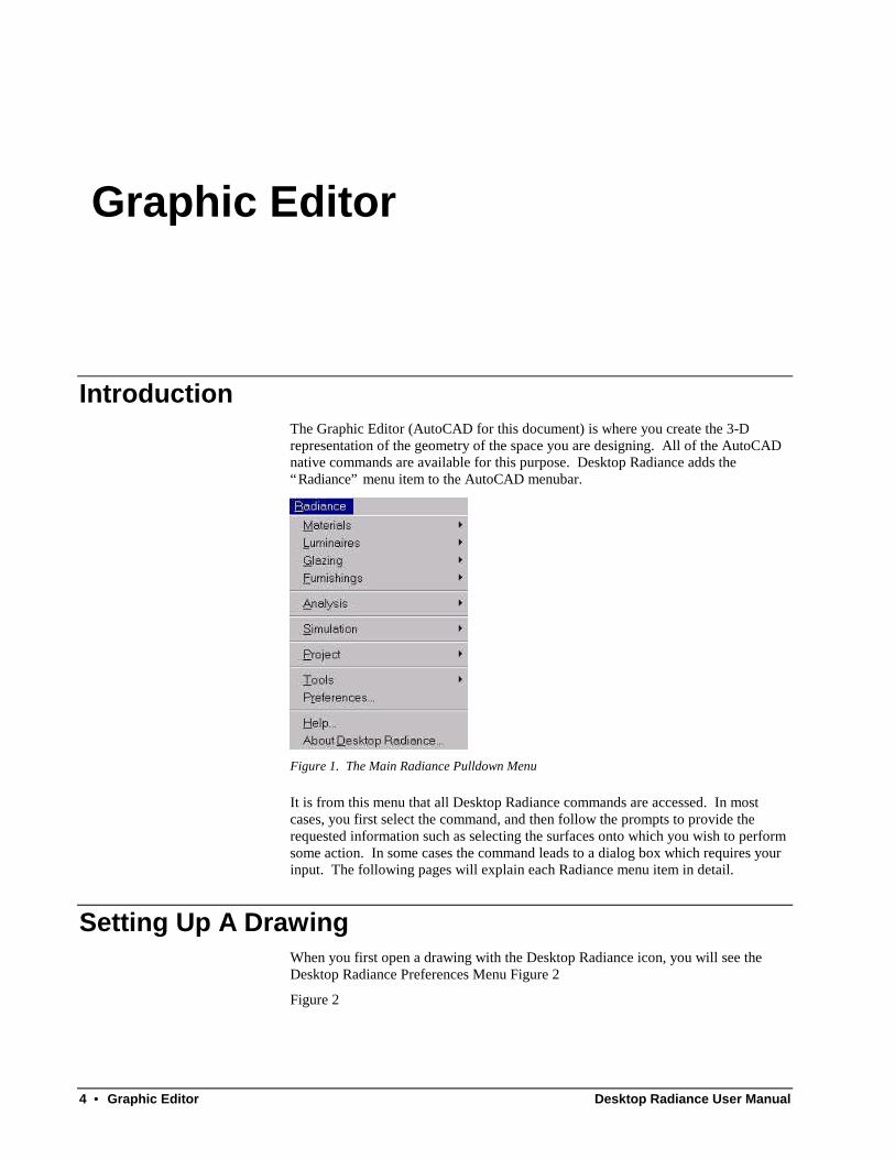
IntroductionThe Graphic Editor (AutoCAD for this document) is where you create the 3-Drepresentation of the geometry of the space you are designing. All of the AutoCADnative commands are available for this purpose. Desktop Radiance adds the“Radiance” menu item to the AutoCAD menubar.
Figure 1. The Main Radiance Pulldown Menu
It is from this menu that all Desktop Radiance commands are accessed. In mostcases, you first select the command, and then follow the prompts to provide therequested information such as selecting the surfaces onto which you wish to performsome action. In some cases the command leads to a dialog box which requires yourinput. The following pages will explain each Radiance menu item in detail.
Setting Up A DrawingWhen you first open a drawing with the Desktop Radiance icon, you will see theDesktop Radiance Preferences Menu Figure 2
Figure 2

Desktop Radiance User Manual Graphic Editor • 5
Figure 2. The Desktop Radiance Prefrences
The Preferences dialog box will appear everytime unless you uncheck the “Show thisdialog whenever a drawing is loaded” option. The best way to get started withmodeling your building is to set up your drawing units. AutoCAD and Radiance areboth “unitless” modeling systems. This means the “size” of a unit of distance isdefined by the user and implemented as a convention. Sometimes a scaling factor isalso used which causes the unit to be proportionately larger or smaller than its baseunit size. These settings for your drawing can be defined in the Preferences DialogBox see Preferences. Once you have set up the units you are ready to start modelingand making attachments from the Radiance menu. Below we will discuss each menuitem in turn starting with the Materials menu item.
MaterialsMaterials can be attached to any surface in your graphic editor 3-D model. Radianceis equipped with an extensive library of materials. You can also create your ownmaterials using the Material Editor that can be reached through Radiance →Materials → New Materials or through the Library Manager. For more informationon creating your own materials, see New Material or Material Editor
Attach materialsThe Materials Library dialog box (Figure 3) contains the database of availablematerials that can be attached to surfaces in your drawing.
6 • Graphic Editor Desktop Radiance User Manual
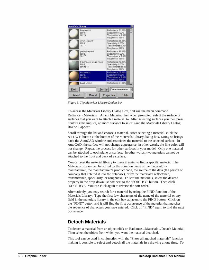
Figure 3. The Materials Library Dialog Box
To access the Materials Library Dialog Box, first use the menu commandRadiance→ Materials→ Attach Material, then when prompted, select the surface orsurfaces that you want to attach a material to. After selecting surfaces you then press<enter> (this implies, no more surfaces to select) and the Materials Library DialogBox will appear.
Scroll through the list and choose a material. After selecting a material, click theATTACH button at the bottom of the Materials Library dialog box. Doing so bringsback the AutoCAD window and associates the material to the selected surface. InAutoCAD, the surface will not change appearance; in other words, the line color willnot change. Repeat the process for other surfaces in your model. Only one materialcan be attached to each plane or surface. In other words, two materials cannot beattached to the front and back of a surface.
You can sort the material library to make it easier to find a specific material. TheMaterials Library can be sorted by the common name of the material, itsmanufacturer, the manufacturer’s product code, the source of the data (the person orcompany that entered it into the database), or by the material’s reflectance,transmittance, specularity, or roughness. To sort the materials, select the desiredproperty in the drop-down list box next to the “SORT BY” button. Then click“SORT BY”. You can click again to reverse the sort order.
Alternatively, you may search for a material by using the FIND function of theMaterials Library. Type the first few characters of the name of the material or anyfield in the materials library in the edit box adjacent to the FIND button. Click onthe “FIND” button and it will find the first occurrence of the material that matchesthe sequence of characters you have entered. Click on “FIND” again to find the nextoccurrence.
Detach MaterialsTo detach a material from an object click on Radiance→ Materials→ Detach Material.Then select the object from which you want the material detached.
This tool can be used in conjunction with the “Show all attached materials” functionmaking it possible to select and detach all the materials in a drawing at one time. To
Desktop Radiance User Manual Graphic Editor • 7
do this go to Radiance→ Materials→ Show All Attached Materials. When allsurfaces are selected go to Radiance→ Materials→ Detach Material. At the prompt itwill ask you to select surfaces to detach the materials from. Type the letter P for theprevious selection set, all surfaces with materials will be selected and highlighted,then hit <enter>. All materials of the highlighted, selected surfaces will be detached.
Show All Attached MaterialsThis function selects all objects that have a material attached to them. To use thisfunction go to Radiance→ Materials→ Show All Attached Materials. The surfaceswith attached materials will become selected and displayed with dashed lines in theGraphic Editor window.
Show Material PropertiesThis function allows you to view detailed information about a specific material.
For more information on how to use the Material Properties Dialog Box (Figure 22)or to create new materials, see Material Properties or the Library Manager.
New MaterialsNew Opaque materials can be created and added to an user database by using theMaterial Editor.
Luminaires
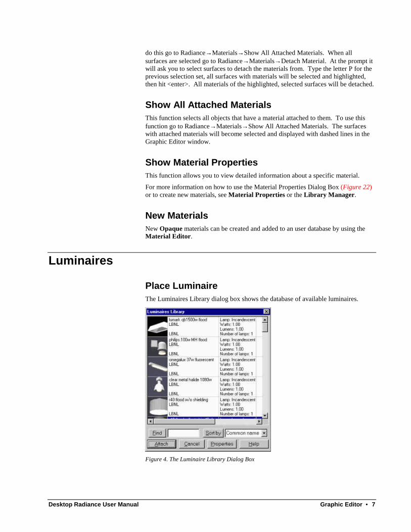
Place LuminaireThe Luminaires Library dialog box shows the database of available luminaires.
Figure 4. The Luminaire Library Dialog Box

8 • Graphic Editor Desktop Radiance User Manual
Modeling Tip:
It is usually easiest if youdisplay an axonometric viewof your drawing to positionthe luminaire into yourdrawing at the correct height.Use the appropriate“snapping” method. Then inplan view you can move theluminaire to the correcthorizontal position.
To access the Luminaires Library Dialog Box select Radiance→ Luminaires→ PlaceLuminaires and the Luminaires Library Dialog Box will appear (Figure 4)
Scroll through the list and select a luminaire to place in your drawing. Next, click theATTACH button at the bottom of the Luminaires Library dialog box. Doing sobrings back the AutoCAD window. Select an insertion point for the luminaire andthen choose a rotation angle. Repeat the process for other luminaires. You can alsocreate your own luminaires with custom IES photometry by using the LuminaireWizard. You can reach the wizard through Radiance → Luminaire → NewLuminaire. For more information on creating luminaires, see New Luminaire.
You can sort the luminaire library to make it easier to find a specific luminaire. Youmay sort the luminaire library by the common name of the luminaire, itsmanufacturer, the manufacturer’s product code, the source of the data (the person orcompany that entered it into the database), the luminaire’s lamp type, dimming level(watts), dimming level (lumens), or number of lamps. To sort the luminaires, selectthe desired property in the drop-down list box next to the “SORT BY” button. Thenclick “SORT BY”. You can click again to reverse the sort order.
Alternatively, you may search for a luminaire by using the FIND function of theLuminaire Library. Type the name of the luminaire or a sequence of charactersmatching any other field in the luminaire library in the edit box adjacent to the FINDbutton. Click on the “FIND” button and it will find the first occurrence of theluminaire that matches the sequence of characters you have entered. Click on“FIND” again to find the next occurrence.
Delete LuminaireTo delete a luminaire from your drawing go to Radiance→ Luminaires→ DeleteLuminaire. Then select the luminaire that you want deleted. The AutoCAD erasecommand also works.
Show Luminaire AimingThis function allows you to see the direction that a luminaire is aimed. To use thistool, go to Radiance→ Luminaires→ Show Luminaire Aiming. Select a luminaire asprompted by the command line. A red arrow will appear that shows the directionthat the luminaire is pointing. To change the luminaire aiming, use the standardobject rotation commands of the Graphic Editor.
In AutoCAD, the best way to aim a luminaire is through a series of rotations aboutthe Z-Axis of the user coordinate system (UCS). First rotate your UCS such that thez-axis is parallel to the axis on which you would like to rotate the luminaire, forexample “UCS, X, 90” will rotate the UCS about the x-axis of the current UCS by 90degrees. Then type the “rotate” command and select a point on the surface of theluminaire.
Show All LuminairesThis function selects all luminaires in your drawing. To access this function go toRadiance→ Luminaires→ Show All Luminaires. All luminaires will becomeselected. This tool can be used in conjunction with “Delete Luminaire” to delete allthe luminaires in your drawing at one time.

Desktop Radiance User Manual Graphic Editor • 9
Show Luminaire PropertiesThis function allows you to view detailed information about a specific luminaire. Ifyou would like to "turn off the lights", you can do so by changing the percentdimming for lumens and watts to 0. 1 means 100% output (no dimming); 0 means0% output (all dimming).
For more information on how to use the Luminaire Properties dialog box see theLuminaire Properties dialog box.
New LuminaireIn addition to the predefined Desktop Radiance luminaires, custom luminaires maybe created through the Luminaire Wizard. Before creating a new luminaire, youwill need to set up your drawing appropriately, create a project directory, andsynchronize your drawing. To enter the Luminaire Wizard from Desktop Radiance,go to Radiance → Luminaires → New Luminaire. Then follow the steps to createyour luminaire.
Glazings
Attach glazingThe Glazings Library dialog box shows the database of available glazings that can beattached to surfaces in your drawing (Figure 5). The Desktop Radiance Glazingdatabase is based on glazing data from the program Optics5 which uses data fromthe National Fenestration Ratings Council, http://www.nfrc.org. For more onOptics5, see http://windows.lbl.gov/Materials/optics5/.
Figure 5. The Glazings Library Dialog Box
To access the Glazings Library Dialog Box go to Radiance→ Glazings→ AttachGlazing. The command line prompts you to select the surfaces that the glazing willbe attached to. After selecting surfaces you then press <enter> (no more surfaces toselect) and the Glazings Library Dialog Box will appear. Scroll through the list and
10 • Graphic Editor Desktop Radiance User Manual
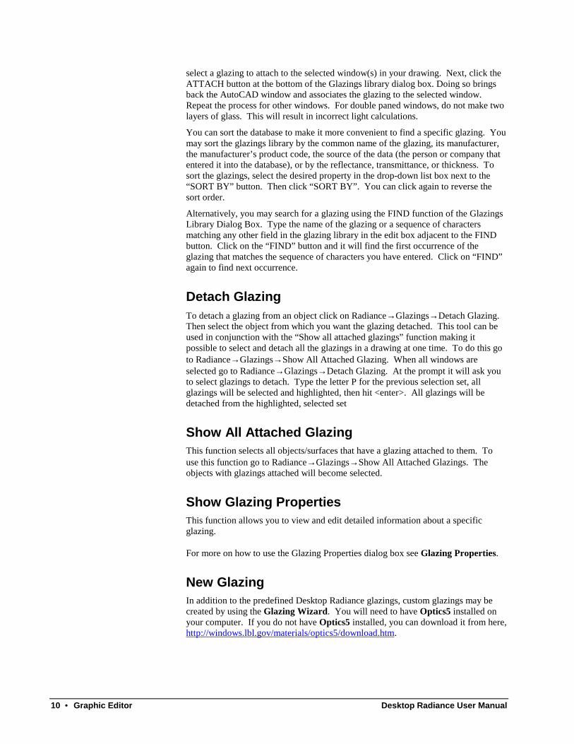
select a glazing to attach to the selected window(s) in your drawing. Next, click theATTACH button at the bottom of the Glazings library dialog box. Doing so bringsback the AutoCAD window and associates the glazing to the selected window.Repeat the process for other windows. For double paned windows, do not make twolayers of glass. This will result in incorrect light calculations.
You can sort the database to make it more convenient to find a specific glazing. Youmay sort the glazings library by the common name of the glazing, its manufacturer,the manufacturer’s product code, the source of the data (the person or company thatentered it into the database), or by the reflectance, transmittance, or thickness. Tosort the glazings, select the desired property in the drop-down list box next to the“SORT BY” button. Then click “SORT BY”. You can click again to reverse thesort order.
Alternatively, you may search for a glazing using the FIND function of the GlazingsLibrary Dialog Box. Type the name of the glazing or a sequence of charactersmatching any other field in the glazing library in the edit box adjacent to the FINDbutton. Click on the “FIND” button and it will find the first occurrence of theglazing that matches the sequence of characters you have entered. Click on “FIND”again to find next occurrence.
Detach GlazingTo detach a glazing from an object click on Radiance→ Glazings→ Detach Glazing.Then select the object from which you want the glazing detached. This tool can beused in conjunction with the “Show all attached glazings” function making itpossible to select and detach all the glazings in a drawing at one time. To do this goto Radiance→ Glazings→ Show All Attached Glazing. When all windows areselected go to Radiance→ Glazings→ Detach Glazing. At the prompt it will ask youto select glazings to detach. Type the letter P for the previous selection set, allglazings will be selected and highlighted, then hit <enter>. All glazings will bedetached from the highlighted, selected set
Show All Attached GlazingThis function selects all objects/surfaces that have a glazing attached to them. Touse this function go to Radiance→ Glazings→ Show All Attached Glazings. Theobjects with glazings attached will become selected.
Show Glazing PropertiesThis function allows you to view and edit detailed information about a specificglazing.
For more on how to use the Glazing Properties dialog box see Glazing Properties.
New GlazingIn addition to the predefined Desktop Radiance glazings, custom glazings may becreated by using the Glazing Wizard. You will need to have Optics5 installed onyour computer. If you do not have Optics5 installed, you can download it from here,http://windows.lbl.gov/materials/optics5/download.htm.
Desktop Radiance User Manual Graphic Editor • 11
Furnishings
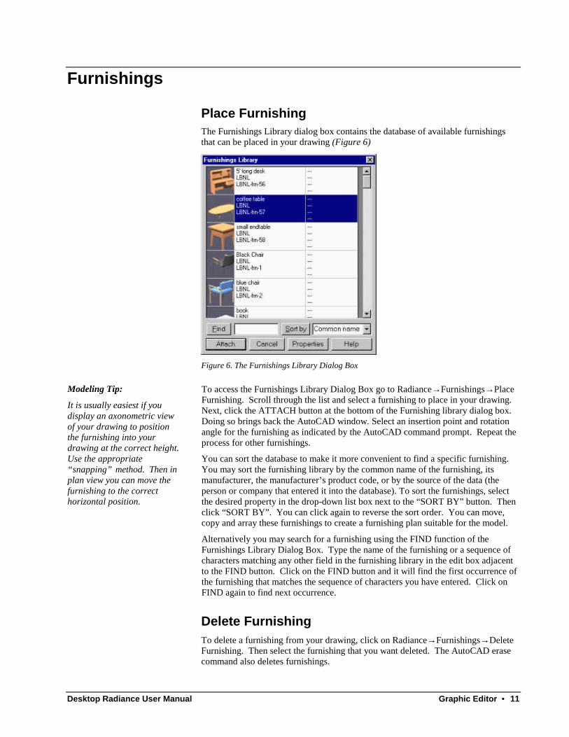
Place FurnishingThe Furnishings Library dialog box contains the database of available furnishingsthat can be placed in your drawing (Figure 6)
Figure 6. The Furnishings Library Dialog Box
Modeling Tip:
It is usually easiest if youdisplay an axonometric viewof your drawing to positionthe furnishing into yourdrawing at the correct height.Use the appropriate“snapping” method. Then inplan view you can move thefurnishing to the correcthorizontal position.
To access the Furnishings Library Dialog Box go to Radiance→ Furnishings→ PlaceFurnishing. Scroll through the list and select a furnishing to place in your drawing.Next, click the ATTACH button at the bottom of the Furnishing library dialog box.Doing so brings back the AutoCAD window. Select an insertion point and rotationangle for the furnishing as indicated by the AutoCAD command prompt. Repeat theprocess for other furnishings.
You can sort the database to make it more convenient to find a specific furnishing.You may sort the furnishing library by the common name of the furnishing, itsmanufacturer, the manufacturer’s product code, or by the source of the data (theperson or company that entered it into the database). To sort the furnishings, selectthe desired property in the drop-down list box next to the “SORT BY” button. Thenclick “SORT BY”. You can click again to reverse the sort order. You can move,copy and array these furnishings to create a furnishing plan suitable for the model.
Alternatively you may search for a furnishing using the FIND function of theFurnishings Library Dialog Box. Type the name of the furnishing or a sequence ofcharacters matching any other field in the furnishing library in the edit box adjacentto the FIND button. Click on the FIND button and it will find the first occurrence ofthe furnishing that matches the sequence of characters you have entered. Click onFIND again to find next occurrence.
Delete FurnishingTo delete a furnishing from your drawing, click on Radiance→ Furnishings→ DeleteFurnishing. Then select the furnishing that you want deleted. The AutoCAD erasecommand also deletes furnishings.

12 • Graphic Editor Desktop Radiance User Manual
Show All FurnishingsThis function selects all furnishings in your drawing. To use this function go toRadiance→ Furnishings→ Show All Furnishings. This tool can be used inconjunction with “Delete Furnishing” to delete all furnishings in a drawing at once.
Show Furnishing PropertiesThis function allows you to view and edit detailed information about a specificfurnishing.
For more on how to use the Furnishing Properties dialog box see FurnishingProperties.
New FurnishingNew furnishing items can be created and added to the database by using theFurnishing wizard.
Desktop Radiance User Manual Graphic Editor • 13
AnalysisDesktop Radiance is equipped with several tools to allow for accurate lightinganalysis of buildings to fit the needs of the designer.
Define ZoneA zone is an optional component of your model.
Use of a zone is recommended when the size of the room you are simulating is lessthan half the size of the entire building model. The zone is used by Radiance toadjust certain calculation parameters to ensure an accurate simulation. A zone wouldbe useful, for instance, if you want to concentrate on a cubicle in an office building.Use the Define Zone function to create a 3-dimensional box for the simulation tofocus on.
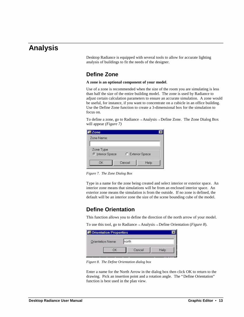
To define a zone, go to Radiance→ Analysis→ Define Zone. The Zone Dialog Boxwill appear (Figure 7)
Figure 7. The Zone Dialog Box
Type in a name for the zone being created and select interior or exterior space. Aninterior zone means that simulations will be from an enclosed interior space. Anexterior zone means the simulation is from the outside. If no zone is defined, thedefault will be an interior zone the size of the scene bounding cube of the model.
Define OrientationThis function allows you to define the direction of the north arrow of your model.
To use this tool, go to Radiance→ Analysis→ Define Orientation (Figure 8).
Figure 8. The Define Orientation dialog box
Enter a name for the North Arrow in the dialog box then click OK to return to thedrawing. Pick an insertion point and a rotation angle. The “Define Orientation”function is best used in the plan view.

14 • Graphic Editor Desktop Radiance User Manual
Note: The North Arrow icon may appear too large or too small if the units have notbeen set up for your drawing. For more on how to adjust this see Preferences.
Figure 9. The AutoCAD North Arrow
Multiple north arrows are possible in one drawing to allow for parametric studies.
The default orientation, if none is defined, is with north pointing up and West to theright, in plan view. You can select North arrow for your simulation in the AdvancedDialog box.
Define camera positionThe define camera position function allows you to create and position a new camera.To use this tool, go to Radiance→ Analysis→ Define Camera Position. The CameraProperties Dialog Box then appears (Figure 10).
Note: ELEVATION is defined by AutoCAD as “The default Z value above or belowthe XY plane of the current user coordinate system… ”, and CURRENTELEVATION is “the Z value that is used whenever a 3D point is exptect but only Xand Y values are supplied.”
Figure 10. The Camera Properties Dialog Box and the camera icon
Enter a name for the camera and set its height. Check the “Height is relative tocurrent elevation” box if you would like the camera’s height to be incremented bythe current ACAD system “elevation” setting. Then set the lens length. The lenslength determines how long the zoom lens is. Smaller numbers make the lens shorterand therefore give a wider, farther away view. Conversely, larger numbers make thelens longer and will therefore give a narrower, closer view. After clicking OK youare brought back to the Graphic Editor window and prompted to give an insertionpoint, a rotation angle, and the height above the insertion point for the origin of thecamera’s view. If you enter a camera name that has already been used in the project,scenarios which use this camera will be changed to the new view parameters. Thecamera icon will then appear in your drawing at the insertion point. If the icon iseither too small or too large, this can be adjusted in the preferences dialog box whichcan be accessed through the Radiance pulldown menu. For more on this, seePreferences.
Desktop Radiance User Manual Graphic Editor • 15
To change the view of a camera first type view↵ r↵ and then type the name of thecamera↵ . The view of the camera will then appear with an outline representing thecamera lens. Type dview↵ . Several commands will appear at the command promptthat allow you to adjust your viewpoint in different ways. Consult the AutoCADhelp section for detailed information on using these commands. Typically the Targetand Zoom commands are very useful. Zoom allows you to zoom forwards and back.Target allows you to move your viewpoint target in all directions. Using these toolsis difficult because your wireframe scene disappears while you make adjustments.After editing your camera view, hit enter at the dview prompt. Your new view willappear in wireframe. If you are satisfied with the view, you must save it with theddview command. If you are unsatisfied with the new view you must return to theoriginal view you started editing and then begin using the dview commands again.Once you are satisfied with the new view, type ddview↵ , to save the new view.Click on New and then enter the same name as the camera view that you wereoriginally editing. Entering the same name will allow you to select the originalcamera icon when starting a simulation, but with the updated view. Entering a newname will mean that you have to select the view name in the camera simulation setupdialog box because there won't be a picture of a camera representing your new view.
In addition to the camera views represented by camera icons, you can also render the“current view”.
The camera view can also be changed more easily and quickly in the winrviewprogram when you start a simulation. This is useful for checking your geometry orto find an ideal view. Custom views can be saved for later use as described in theFile→ Append View to rif file and File → Append View to view file sections of theInteractive Rendering chapter.
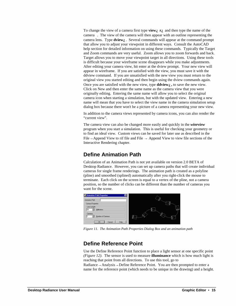
Define Animation PathCalculation of an Animation Path is not yet available on version 2.0 BETA ofDesktop Radiance. However, you can set up camera paths that will create individualcameras for single frame renderings. The animation path is created as a polyline(pline) and smoothed (splined) automatically after you right-click the mouse toterminate. Each click on the screen is equal to a vertex of the pline, not a cameraposition, so the number of clicks can be different than the number of cameras youwant for the scene.
Figure 11. The Animation Path Properties Dialog Box and an animation path
Define Reference PointUse the Define Reference Point function to place a light sensor at one specific point(Figure 12). The sensor is used to measure illuminance which is how much light isreaching that point from all directions. To use this tool, go toRadiance→ Analysis→ Define Reference Point. You are then prompted to enter aname for the reference point (which needs to be unique in the drawing) and a height.

16 • Graphic Editor Desktop Radiance User Manual
You should be aware of your drawing's current elevation and enter a height that isappropriate.
Figure 12. The Reference Point Properties dialog box
After clicking OK, you will return to the drawing and be ready to place the sensorreference point (Figure 13).
Figure 13. A Reference Point Sensor
Define Reference GridUse Define Reference Grid to create a plane within the model where illuminancevalues can be measured. To define a reference grid go toRadiance→ Analysis→ Define Reference Grid (Figure 14).
Figure 14. Grid Properties Dialog Box
Enter a name for the reference grid and the number of columns and rows for theilluminance grid, then click OK to return to your drawing. Then click in yourdrawing to select the opposing corners of the grid. If you are in a perspective viewwhen defining the corners of the grid, the box being defined will not appear to fit theplane in perspective until after you have selected both corners.
The reference grid can be moved to the correct height and position by using standardgraphic editor commands if necessary.
Note: Reference points and grids should be positioned above any occludingsurfaces. This means that the height of the points and grids should be a fraction of aunit larger than the surface’s height.
Desktop Radiance User Manual Graphic Editor • 17
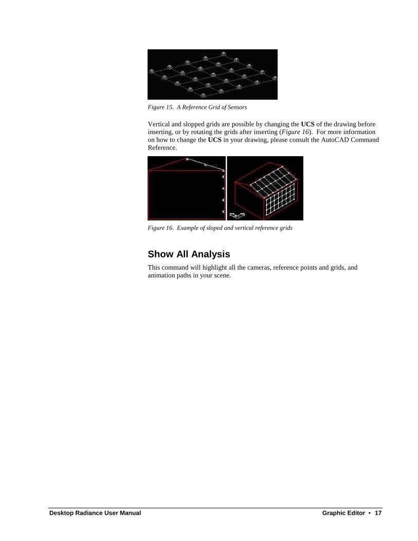
Figure 15. A Reference Grid of Sensors
Vertical and slopped grids are possible by changing the UCS of the drawing beforeinserting, or by rotating the grids after inserting (Figure 16). For more informationon how to change the UCS in your drawing, please consult the AutoCAD CommandReference.
Figure 16. Example of sloped and vertical reference grids
Show All AnalysisThis command will highlight all the cameras, reference points and grids, andanimation paths in your scene.
18 • Graphic Editor Desktop Radiance User Manual
SimulationThe simulation process can begin when all the Radiance attachments and settings areready to create a picture or calculate a point or grid quantity of your model. Thisprocess begins by selecting a camera, reference point, or reference grid to simulate.Then the scenario or simulation needs to be named and you choose the location, date,and time that the scenario should portray. These parameters then become part of asingle scenario.
When a simulation is done, it can be viewed first in the InteractiveRendering(rview) and then in the Image Analyzer.
CameraThis function allows you to begin a Radiance simulation of your drawing.
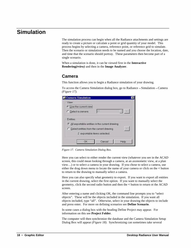
To access the Camera Simulation dialog box, go to Radiance→ Simulation→ Camera(Figure 17).
Figure 17. Camera Simulation Dialog Box.
Here you can select to either render the current view (whatever you see in the ACADscreen, this could mean looking through a camera, at an axonometic view, at a planview… ) or to select a camera in your drawing. If you chose to select a camera, useeither the drag down menu to locate the name of your camera or click on the < buttonto return to the drawing to manually select a camera.
Here you can also specify what geometry to export. If you want to export all entitiesin the current drawing, select the first option. If you want to manually select thegeometry, click the second radio button and then the < button to return ot the ACADscreen.
After entering a name and clicking OK, the command line prompts you to “selectobjects”. These will be the objects included in the simulation. If you want allobjects included, type “all”. Otherwise, select in your drawing the objects to includeand press enter. For more on defining scenarios see Define Scenario.
In some cases a dialog box with the heading Define Project may appear. Forinformation on this see Project Folder.
The computer will then synchronize the database and the Camera Simulation SetupDialog Box will appear (Figure 18). Synchronizing can sometimes take several

Desktop Radiance User Manual Graphic Editor • 19
minutes to complete for large models as the selected library items are copied to yourproject directory. For more on simulating your model see Simulation Manager.
Figure 18. The Camera Simulation Setup Dialog Box.
Reference Point
Figure 19. The Reference Point Simulation Dialog Box
This tool runs a simulation of a light sensor (reference point) in your model. Itproduces an illuminance value at the sensor for the scenario you have defined. Touse this tool, go to RadianceàSimulationàReference Point.
To place a sensor see Define Reference Point.
20 • Graphic Editor Desktop Radiance User Manual
Reference Grid
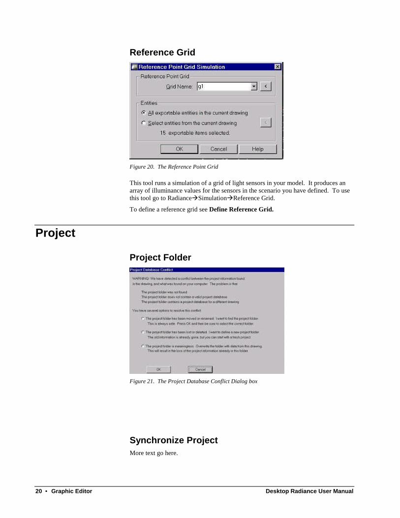
Figure 20. The Reference Point Grid
This tool runs a simulation of a grid of light sensors in your model. It produces anarray of illuminance values for the sensors in the scenario you have defined. To usethis tool go to RadianceàSimulationàReference Grid.
To define a reference grid see Define Reference Grid.
Project
Project Folder
Figure 21. The Project Database Conflict Dialog box
Synchronize ProjectMore text go here.

Desktop Radiance User Manual Graphic Editor • 21
Duplicate ProjectMore text go here.
ToolsThe Radiance tools menu items consist of utilities that assist in the management ofyour drawing model and the corresponding Radiance project files.
Show All AttachmentsThis function highlights and selects all luminaires, furnishings, and surfaces withmaterials or glazings attached to them. To access this tool go toRadiance→ Tools→ Show All Attachments. All Radiance attachments will becomehighlighted. The AutoCAD “previous” command can be used within a subsequentcommand to act upon these objects. .
Show All UnattachedThis function selects and highlights all the objects and surfaces in the drawing thatdo not have a material or glazing attached to them. To use this tool go toRadiance→ Tools→ Show All Unattached. Objects and surfaces without Radianceattachments will become highlighted. The AutoCAD “previous” command can beused within a subsequent command to act upon these objects.
Show PropertiesThis function allows you to view specific properties of Radiance elements includingFurnishings, Materials, Glazings, and Luminaires, reference points, grids, cameras,and arrows.
To access this function, go to Radiance→ Tools→ Show Properties. Then select amaterial, glazing, furnishing, or luminaire in your drawing.
Material PropertiesTo access the Material Properties dialog box (Figure 22) go toRadiance→ Tools→ Show Properties and then select a material in your drawing.

22 • Graphic Editor Desktop Radiance User Manual
Figure 22. The Material Properties Dialog Box.
When attaching a new material, the Material Properties dialog can also be accessedby clicking on the PROPERTIES button at the bottom of the Materials Librarydialog box.
You can change certain properties (comments) of a material in the MaterialProperties dialog box. This is done by adding inputs and clicking apply.
To create new materials you can go through either the Material Properties DialogBox or through the Library Browser (see Library Manager).
Furnishing PropertiesTo access the Furnishing Properties dialog box (Figure 23) go toRadiance→ Tools→ Show Properties and then select a furnishing in your drawing.

Desktop Radiance User Manual Graphic Editor • 23
Figure 23. The Furnishing Properties Dialog Box.
The Furnishing Properties dialog can be accessed from the Furnishings Librarydialog box when placing a new furnishing or from the Library Browser. In theFurnishings Library dialog box highlight a furnishing and click on the PROPERTIESbutton.
Glazing PropertiesTo access the Glazing Properties dialog box (Figure 24) go toRadiance→ Tools→ Show Properties and then select a glazing in your drawing.
24 • Graphic Editor Desktop Radiance User Manual
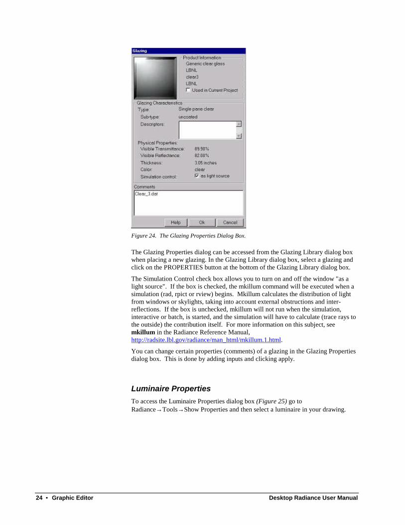
Figure 24. The Glazing Properties Dialog Box.
The Glazing Properties dialog can be accessed from the Glazing Library dialog boxwhen placing a new glazing. In the Glazing Library dialog box, select a glazing andclick on the PROPERTIES button at the bottom of the Glazing Library dialog box.
The Simulation Control check box allows you to turn on and off the window "as alight source". If the box is checked, the mkillum command will be executed when asimulation (rad, rpict or rview) begins. Mkillum calculates the distribution of lightfrom windows or skylights, taking into account external obstructions and inter-reflections. If the box is unchecked, mkillum will not run when the simulation,interactive or batch, is started, and the simulation will have to calculate (trace rays tothe outside) the contribution itself. For more information on this subject, seemkillum in the Radiance Reference Manual,http://radsite.lbl.gov/radiance/man_html/mkillum.1.html.
You can change certain properties (comments) of a glazing in the Glazing Propertiesdialog box. This is done by adding inputs and clicking apply.
Luminaire PropertiesTo access the Luminaire Properties dialog box (Figure 25) go toRadiance→ Tools→ Show Properties and then select a luminaire in your drawing.

Desktop Radiance User Manual Graphic Editor • 25
Figure 25. The Luminaire Properties Dialog Box.
When placing a new luminaire, the Luminaire Properties dialog can be accessed byclicking on the PROPERTIES button at the bottom of the Luminaire Library dialogbox.
Detach AllThis function detaches all materials, glazings, furnishings, and luminaires fromobjects and surfaces in the model.
To use this tool go to Radiance→ Tools→ Detach All. All objects with Radianceattachments will be selected automatically and a window appears to confirm that youwant to detach all Radiance materials and glazings. This restores your drawing tothe state it was in before the use of any Desktop Radiance commands.
Note: Detach all should be used with caution. Save your drawing and/or make abackup drawing before using this command because all of your work may be lost.Detach all is sometimes useful to debug problems you may be having with yourdrawing.
Adjust Surface NormalsThis command is used to check and adjust the orientation of surfaces in your model.In general, the orientation of surfaces is not important for Radiance as it is with otherlighting analysis tools. However, to calculate the distribution of daylight withglazings to be treated as a “light source”, it is necessary to have the glazing surfacecorrectly oriented. Material surfaces do not need correct surface normal orientation.To use this function, go to Radiance→ Tools→ Adjust Surface Normals. Then, asyou are prompted, select the glazing surface in your drawing. A red arrow willappear within the window (Figure 26).

26 • Graphic Editor Desktop Radiance User Manual
Figure 26. A surface with the Adjust Surface Normal arrow showing orientation
A correctly oriented surface normal for a window or skylight should be pointing inthe direction of daylight travel from brightest to dimmest regions. The commandline asks you if you want to flip the surface normal. Type “N” if the arrow ispointing in the correct direction and “Y” if you want to switch it. If the direction ofthe surface normal is not as you expected and cannot be reversed with this tool, thenthe window surface needs to be recreated. Certain ACAD entities, ie region andbody, have surface normals that are intrinsic to the object itself and therefore cannotbe altered with this tool. Those need to be recreated if they are to be correctlyoriented as glazing surfaces.
If the red surface normal arrow does not appear it may be that you are checking anobject that Desktop Radiance can't figure the front or back of, for example anexploded ACIS solid. The surfaces of an exploded ACIS solid will have normalspointing outwards. If the surface normal you are checking is not that of a surface ofan exploded ACIS object and you don't see the red surface normal arrow, seePreferences.
If you would like to create your glazing surfaces with the proper orientation whenyou first draw them, use the Right Hand Rule.. Imagine placing your right handagainst the wall with the window, with your thumb pointing in the direction that thelight travels. Your four fingers now curl in the direction that the vertices should becreated to obtain a properly oriented surface.
Material MapThe Material Map function associates a surface with a specific layer or line color inyour graphic editor program or the specified Desktop Radiance material. To use thematerial map tool go to Radiance→ Tools→ Material Map and then the Material Mapdialog box will appear (Figure 27).
Figure 27. The Material Map Dialog Box
Desktop Radiance User Manual Graphic Editor • 27
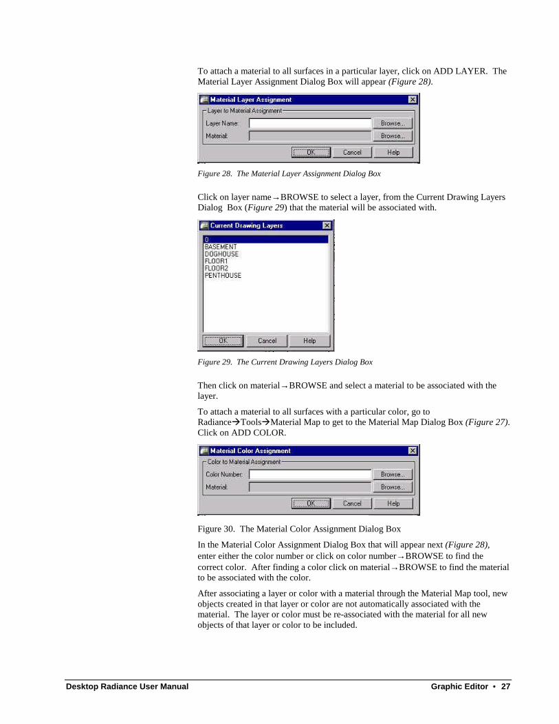
To attach a material to all surfaces in a particular layer, click on ADD LAYER. TheMaterial Layer Assignment Dialog Box will appear (Figure 28).
Figure 28. The Material Layer Assignment Dialog Box
Click on layer name→ BROWSE to select a layer, from the Current Drawing LayersDialog Box (Figure 29) that the material will be associated with.
Figure 29. The Current Drawing Layers Dialog Box
Then click on material→ BROWSE and select a material to be associated with thelayer.
To attach a material to all surfaces with a particular color, go toRadianceàToolsàMaterial Map to get to the Material Map Dialog Box (Figure 27).Click on ADD COLOR.
Figure 30. The Material Color Assignment Dialog Box
In the Material Color Assignment Dialog Box that will appear next (Figure 28),enter either the color number or click on color number→ BROWSE to find thecorrect color. After finding a color click on material→ BROWSE to find the materialto be associated with the color.
After associating a layer or color with a material through the Material Map tool, newobjects created in that layer or color are not automatically associated with thematerial. The layer or color must be re-associated with the material for all newobjects of that layer or color to be included.
28 • Graphic Editor Desktop Radiance User Manual
NOTE: As of Version 1.02, the only name allowed for saving a map file issavemap.lcm. Any unique name you input will be ignored and the defaultsavemap.lcm name used.
Library ManagerThis tool allows you to easily keep track of all available Radiance libraries, theseinclude Furnishings, Glazings, Materials, and Luminaires (see Library Manager).
Future Plans for the Library Manager:
The Library Manager is still rapidly changing and developing.
Material EditorThis tool allows you to edit existing materials and create new materials altogether.For information on using the Material Editor see Material Editor.
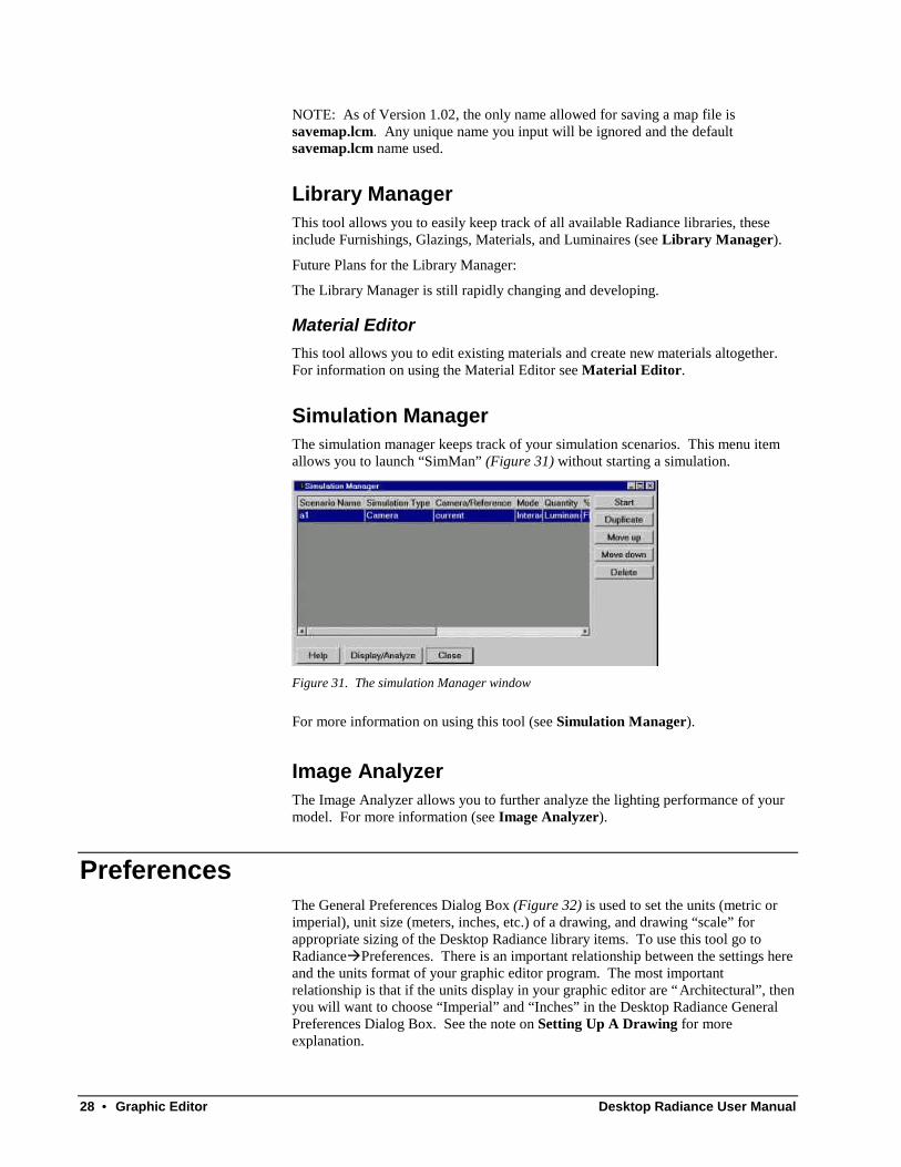
Simulation ManagerThe simulation manager keeps track of your simulation scenarios. This menu itemallows you to launch “SimMan” (Figure 31) without starting a simulation.
Figure 31. The simulation Manager window
For more information on using this tool (see Simulation Manager).
Image AnalyzerThe Image Analyzer allows you to further analyze the lighting performance of yourmodel. For more information (see Image Analyzer).
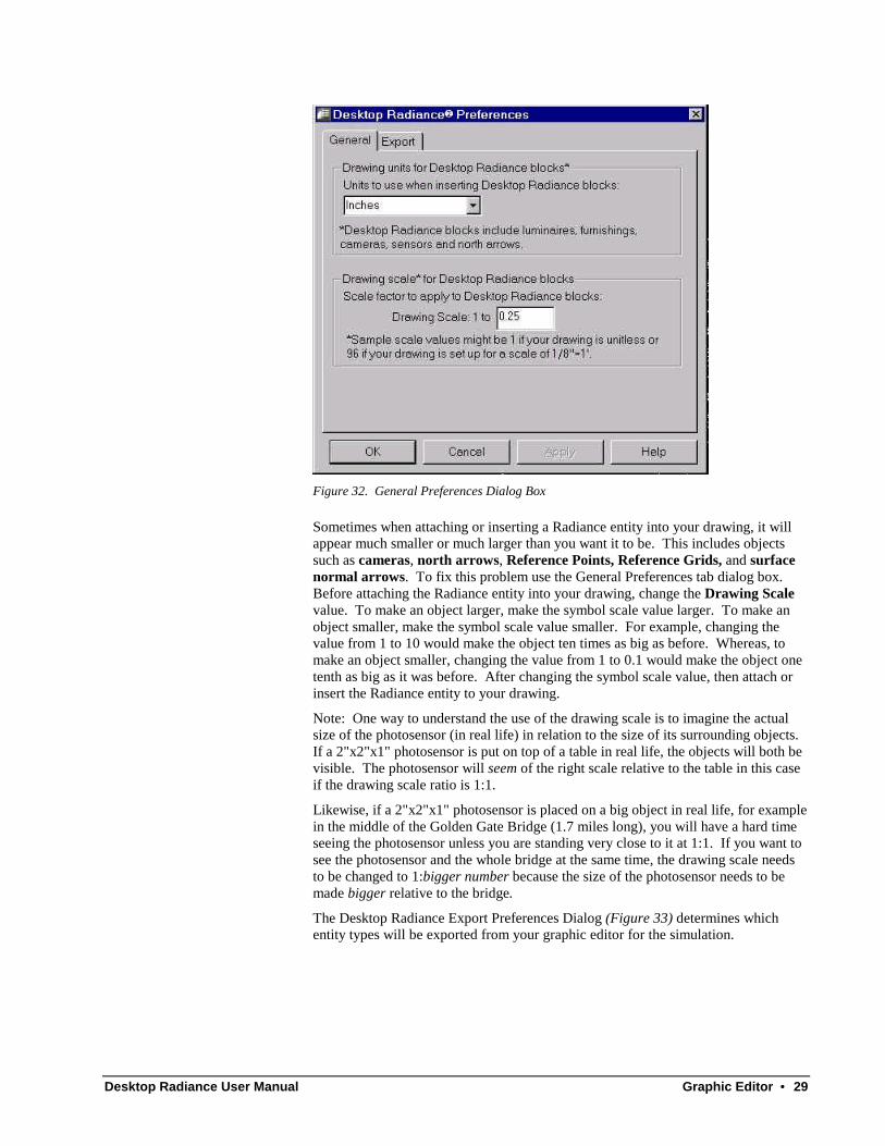
PreferencesThe General Preferences Dialog Box (Figure 32) is used to set the units (metric orimperial), unit size (meters, inches, etc.) of a drawing, and drawing “scale” forappropriate sizing of the Desktop Radiance library items. To use this tool go toRadianceàPreferences. There is an important relationship between the settings hereand the units format of your graphic editor program. The most importantrelationship is that if the units display in your graphic editor are “Architectural”, thenyou will want to choose “Imperial” and “Inches” in the Desktop Radiance GeneralPreferences Dialog Box. See the note on Setting Up A Drawing for moreexplanation.
Desktop Radiance User Manual Graphic Editor • 29
Figure 32. General Preferences Dialog Box
Sometimes when attaching or inserting a Radiance entity into your drawing, it willappear much smaller or much larger than you want it to be. This includes objectssuch as cameras, north arrows, Reference Points, Reference Grids, and surfacenormal arrows. To fix this problem use the General Preferences tab dialog box.Before attaching the Radiance entity into your drawing, change the Drawing Scalevalue. To make an object larger, make the symbol scale value larger. To make anobject smaller, make the symbol scale value smaller. For example, changing thevalue from 1 to 10 would make the object ten times as big as before. Whereas, tomake an object smaller, changing the value from 1 to 0.1 would make the object onetenth as big as it was before. After changing the symbol scale value, then attach orinsert the Radiance entity to your drawing.
Note: One way to understand the use of the drawing scale is to imagine the actualsize of the photosensor (in real life) in relation to the size of its surrounding objects.If a 2"x2"x1" photosensor is put on top of a table in real life, the objects will both bevisible. The photosensor will seem of the right scale relative to the table in this caseif the drawing scale ratio is 1:1.
Likewise, if a 2"x2"x1" photosensor is placed on a big object in real life, for examplein the middle of the Golden Gate Bridge (1.7 miles long), you will have a hard timeseeing the photosensor unless you are standing very close to it at 1:1. If you want tosee the photosensor and the whole bridge at the same time, the drawing scale needsto be changed to 1:bigger number because the size of the photosensor needs to bemade bigger relative to the bridge.
The Desktop Radiance Export Preferences Dialog (Figure 33) determines whichentity types will be exported from your graphic editor for the simulation.

30 • Graphic Editor Desktop Radiance User Manual
Figure 33. The Export Preferences Dialog Box
The layer options allow you to modify which entities of your drawing will beincluded in the simulation. They refer to the various layer settings in your GraphicEditor program. The Geometry option determines whether you want all geometry tobe exported automatically for simulations or if you want to select particularGeometry yourself. Closed or Extruded 2D Geometry and 3D Geometry refer totypes of geometry that can be included in simulations.

Desktop Radiance User Manual Library Manager • 31
32 • Library Manager Desktop Radiance User Manual
Library Manager
IntroductionThe Library Manager is a collection of tools related to the maintenance of theDesktop Radiance Material, Luminaire, Glazing, and Furnishing libraries. ThisLibrary Browser allows you to view detailed information about RadianceFurnishings, Glazings, Luminaires, and Materials. The Editor and wizards allowsyou to create new Desktop Radiance materials, glazings, luminaires and furnishings.
All items added to the libraries are accessible to any user of Desktop Radiance orusers who share the same main database.
To reach the Library Browser from inside the Graphic Editor, go to Radiance →Tools → Library Manager. Select the appropriate tab for Furnishings, Glazings,Luminaires, or Materials.
The current state of the Library Browser does not include all future functionality.Future version will have the ability to edit specific library items and to move itemsbetweendifferent installations of Desktop Radiance.
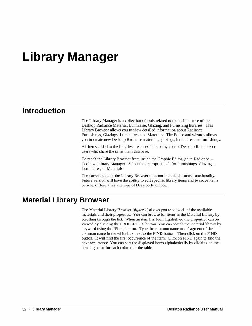
Material Library BrowserThe Material Library Browser (figure 1) allows you to view all of the availablematerials and their properties. You can browse for items in the Material Library byscrolling through the list. When an item has been highlighted the properties can beviewed by clicking the PROPERTIES button. You can search the material library bykeyword using the “Find” button. Type the common name or a fragment of thecommon name in the white box next to the FIND button. Then click on the FINDbutton. It will find the first occurrence of the item. Click on FIND again to find thenext occurrence. You can sort the displayed items alphabetically by clicking on theheading name for each column of the table.

Desktop Radiance User Manual Library Manager • 33
Figure 34. The Material Library Browser
Material EditorIn addition to the predefined Desktop Radiance materials, custom materials may becreated in the Material Editor. Currently only reflective materials can be created. Itis also not yet possible to “edit” existing materials in the library. To enter theMaterial Editor (figure 1) from Desktop Radiance, go to Radiance → Materials →New Material (figure 2) Material Editor may also be opened by choosing its icon(created by the install program) from the Start Menu in the Desktop Radiancedirectory.. From in the Material Library Browser, click on the NEW button andenter a new material name when prompted. For every custom material that youcreate, the Material Editor needs to know the Material Type, Red, Green, and Bluevalues and Specularity and Roughness values. You may optionally specifyinformation about the manufacturer of this material from the “manufacturer” button.
34 • Library Manager Desktop Radiance User Manual
Figure 35. Material Editor
Material TypeTo set material type, use the pull down menu located below the Material Name field.Currently only plastic and metal may be created. Plastic materials include all opaquematerials that have colored diffuse reflections but uncolored specular (shiny)components. Plastic materials include formica, tile, glossy paint, and any similarsurfaces. Materials that have colored specular highlights are appropriately modeledas “metal”. Metal materials include bronze, gold, copper, aluminum, and similarsurfaces. (More on this in Physical Properties)
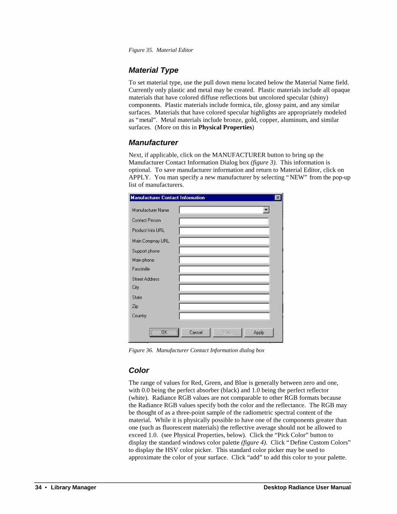
ManufacturerNext, if applicable, click on the MANUFACTURER button to bring up theManufacturer Contact Information Dialog box (figure 3). This information isoptional. To save manufacturer information and return to Material Editor, click onAPPLY. You man specify a new manufacturer by selecting “NEW” from the pop-uplist of manufacturers.
Figure 36. Manufacturer Contact Information dialog box
ColorThe range of values for Red, Green, and Blue is generally between zero and one,with 0.0 being the perfect absorber (black) and 1.0 being the perfect reflector(white). Radiance RGB values are not comparable to other RGB formats becausethe Radiance RGB values specify both the color and the reflectance. The RGB maybe thought of as a three-point sample of the radiometric spectral content of thematerial. While it is physically possible to have one of the components greater thanone (such as fluorescent materials) the reflective average should not be allowed toexceed 1.0. (see Physical Properties, below). Click the “Pick Color” button todisplay the standard windows color palette (figure 4). Click “Define Custom Colors”to display the HSV color picker. This standard color picker may be used toapproximate the color of your surface. Click “add” to add this color to your palette.
Desktop Radiance User Manual Library Manager • 35
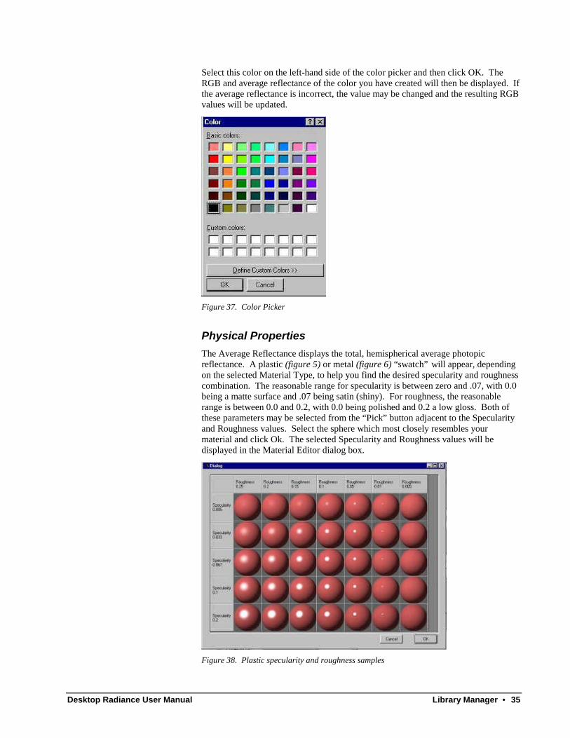
Select this color on the left-hand side of the color picker and then click OK. TheRGB and average reflectance of the color you have created will then be displayed. Ifthe average reflectance is incorrect, the value may be changed and the resulting RGBvalues will be updated.
Figure 37. Color Picker
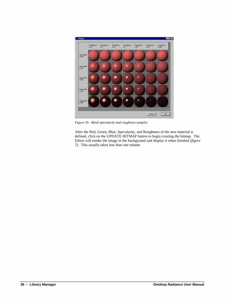
Physical PropertiesThe Average Reflectance displays the total, hemispherical average photopicreflectance. A plastic (figure 5) or metal (figure 6) “swatch” will appear, dependingon the selected Material Type, to help you find the desired specularity and roughnesscombination. The reasonable range for specularity is between zero and .07, with 0.0being a matte surface and .07 being satin (shiny). For roughness, the reasonablerange is between 0.0 and 0.2, with 0.0 being polished and 0.2 a low gloss. Both ofthese parameters may be selected from the “Pick” button adjacent to the Specularityand Roughness values. Select the sphere which most closely resembles yourmaterial and click Ok. The selected Specularity and Roughness values will bedisplayed in the Material Editor dialog box.
Figure 38. Plastic specularity and roughness samples
36 • Library Manager Desktop Radiance User Manual
Figure 39. Metal specularity and roughness samples
After the Red, Green, Blue, Specularity, and Roughness of the new material isdefined, click on the UPDATE BITMAP button to begin creating the bitmap. TheEditor will render the image in the background and display it when finished (figure7). This usually takes less than one minute.
Desktop Radiance User Manual Library Manager • 37
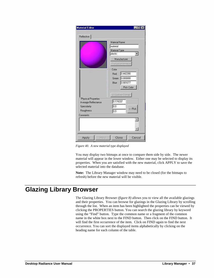
Figure 40. A new material type displayed
You may display two bitmaps at once to compare them side by side. The newermaterial will appear in the lower window. Either one may be selected to display itsproperties. When you are satisfied with the new material, click APPLY to save theselected material into the database.
Note: The Library Manager window may need to be closed (for the bitmaps torefresh) before the new material will be visible.
Glazing Library BrowserThe Glazing Library Browser (figure 8) allows you to view all the available glazingsand their properties. You can browse for glazings in the Glazing Library by scrollingthrough the list. When an item has been highlighted the properties can be viewed byclicking the PROPERTIES button. You can search the glazing library by keywordusing the “Find” button. Type the common name or a fragment of the commonname in the white box next to the FIND button. Then click on the FIND button. Itwill find the first occurrence of the item. Click on FIND again to find the nextoccurrence. You can sort the displayed items alphabetically by clicking on theheading name for each column of the table.

38 • Library Manager Desktop Radiance User Manual
Figure 41. The Glazing Library Browser
Glazing Editor (Glazing Wizard)In addition to the predefined Desktop Radiance glazings, you can create customglazings using the Glazing Wizard. The Glazing Wizard guides you through thesteps necessary to create a new glazing and add it to the Glazing Library. Thewizard relies upon the Lawrence Berkeley National Laboratory program calledOptics5 included with this version of Desktop Radiance. Optics 5 (figure 10), usesoptical data from the National Fenestration Rating Council (NFRC) spectral datalibrary and allows you to create a Radiance description of a multi-layered glazingassembly. To enter the Glazing Editor from Desktop Radiance, go to Radiance →Glazings → New Glazing. Or select the Glazings tab of the Library Manager andclick NEW. At this point you will see the "Welcome to the Desktop RadianceGlazing Wizard" screen (figure 9).
Figure 42 The "Welcome to the Desktop Radiance Glazing Wizard" screen.
"Welcome to the Desktop Radiance Glazing Wizard"
If you have already completed the modeling of your glazing with Optics5 and havesaved it as a Radiance glazing file, you can click on the "next" button in the GlazingWizard welcome page (the page currently open), and you will be lead to the “Selectthe drawing and project folder” screen. Otherwise, select the checkbox to be givenassistance on how to work with the Optics5 program to model the glazing you need,beginning from “How to model a glazing and prepare it for the Desktop RadianceLibrary”.
"How to model a glazing and prepare it for the Desktop Radiance Library"
The Wizard has started the Optics5 program and should now be running as a separateapplication. Check your taskbar if it does not immediately appear. .
Desktop Radiance User Manual Library Manager • 39
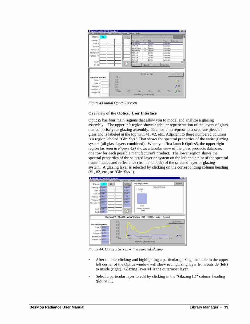
Figure 43 Initial Optics 5 screen
Overview of the Optics5 User Interface
Optics5 has four main regions that allow you to model and analyze a glazingassembly. The upper left region shows a tabular representation of the layers of glassthat comprise your glazing assembly. Each column represents a separate piece ofglass and is labeled at the top with #1, #2, etc.. Adjacent to these numbered columnsis a region labeled "Glz. Sys." That shows the spectral properties of the entire glazingsystem (all glass layers combined). When you first launch Optics5, the upper rightregion (as seen in Figure 43) shows a tabular view of the glass products database,one row for each possible manufacturer's product. The lower region shows thespectral properties of the selected layer or system on the left and a plot of the spectraltransmittance and reflectance (front and back) of the selected layer or glazingsystem. A glazing layer is selected by clicking on the corresponding column heading(#1, #2, etc., or "Glz. Sys.").
Figure 44. Optics 5 Screen with a selected glazing
• After double-clicking and highlighting a particular glazing, the table in the upperleft corner of the Optics window will show each glazing layer from outside (left)to inside (right). Glazing layer #1 is the outermost layer.
• Select a particular layer to edit by clicking in the "Glazing ID" column heading(figure 11).

40 • Library Manager Desktop Radiance User Manual
• Select the specific manufacturer's product to view its properties in the lowerregion of the dialog. Double-click on a glazing product to assign the specificglass product to the selected layer.
• Repeat this process for the subsequent layers of your glazing assembly, if any.
• Use "File → Create Radiance file..." to save the glazing as a Radiance input filewith a .RAD extension. Select a convenient directory to save this file so youcan refer to it in a later wizard screen. When the glazing file is saved, click"Next" to continue to the next glazing wizard screen.
If you need more help with Optics5, please refer to the Optics5 help menu.
"Select the drawing and project folder"
At this point we assume that you have already modeled the new glazing and have theOptics5 Radiance file ready. If not, please click the "back" button to be guidedthrough this process (see above).
Figure 45. The "Select the Drawing and Project Folder" screen.
• In the box next to “Glazing Name”, specify the glazing .RAD file name, or click"Browse… " to search for it using the standard open file dialog box (figure 12).
"Describe new glazing"
• The glazing manufacturer, model name or number, and item description willhelp you identify this glazing item in the library browser. If the manufacturername is not included in the list, you can click the "New Manufacturer..." buttonto define a new manufacturer name.
• Provide the information specified and click "Next" to continue (figure 13).
Figure 46. The "Describe New Glazing" screen.
"New Glazing Preview"

Desktop Radiance User Manual Library Manager • 41
Click the preview button on the New Glazing Preview screen (figure 14) to inspectyour new glazing item before committing it to the library, and to create a previewimage for the browser. To create the preview image, use the File → Save as...command of Winrview to save the image. The default name oct_V1.pic needs tobe changed to reflect the actual name of your item (Figure 47) and (Figure 48) .In this example, the drawing name is testglzwiz1 so the image name has to betestglzwiz1.pic.
Figure 47. The Save Picture Dialog box of the Glazing Wizard with default file name
Figure 48. The Save Picture Dialog box of the Glazing Wizard with correct file name

42 • Library Manager Desktop Radiance User Manual
Figure 49. The "New Glazing Preview" screen.
You are now ready to make this glazing a permanent part of your database. Click"Finished" when you are ready to commit this item to the library.
Note: The Library Manager window may need to be closed (for the bitmaps torefresh) before the new glazing will be visible.
You have now successfully completed the creation of a new glazing item forDesktop Radiance. You can return to the library browser to view your customglazing item, or you can return to AutoCAD to attach it to the appropriate surface(s)of your model.
NOTE: If the spectral data library is out of date, updates are available from theNFRC's Spectral Data Library webpage, http://www.nfrc.org/sdl.html/ . Afterdownloading, extract contents into a convenient temporary directory.
Then in Optics5, use the "File → Add files to User Database… command to select thespectra data file(s) to be merged with the User Database. Please see the Optics5 on-line user manual for more information. Updates for Optics5 are available fromhttp://windows.lbl.gov/materials/optics5/ .
Furnishing Library BrowserThe Furnishing Library Browser allows you to view all available furnishings andtheir properties. The Furnishing Library Browser (figure 15) allows you to view allthe available furnishings and their properties. You can browse for items in theFurnishing Library by scrolling through the list. When an item has been highlightedthe properties can be viewed by clicking the PROPERTIES button. You can searchthe furnishing library by keyword using the “Find” button. Type the common nameor a fragment of the common name in the white box next to the FIND button. Thenclick on the FIND button. It will find the first occurrence of the item. Click onFIND again to find the next occurrence. You can sort the displayed itemsalphabetically by clicking on the heading name for each column of the table.
Desktop Radiance User Manual Library Manager • 43
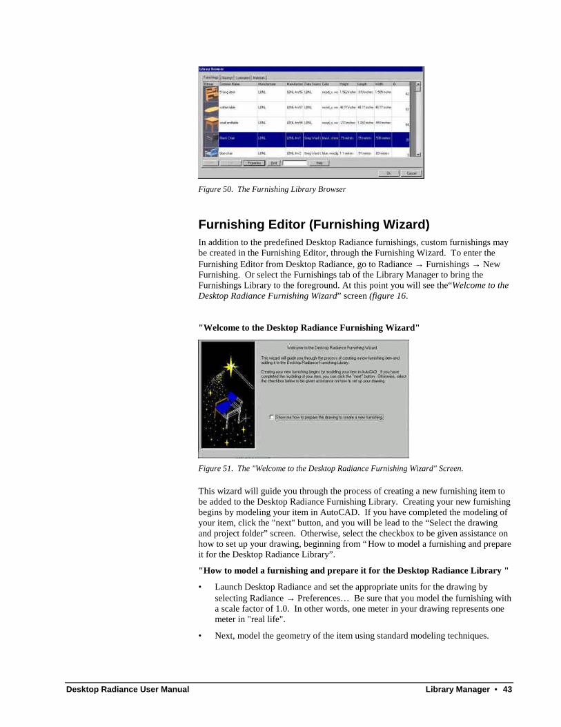
Figure 50. The Furnishing Library Browser
Furnishing Editor (Furnishing Wizard)In addition to the predefined Desktop Radiance furnishings, custom furnishings maybe created in the Furnishing Editor, through the Furnishing Wizard. To enter theFurnishing Editor from Desktop Radiance, go to Radiance → Furnishings → NewFurnishing. Or select the Furnishings tab of the Library Manager to bring theFurnishings Library to the foreground. At this point you will see the“Welcome to theDesktop Radiance Furnishing Wizard” screen (figure 16.
"Welcome to the Desktop Radiance Furnishing Wizard"
Figure 51. The "Welcome to the Desktop Radiance Furnishing Wizard" Screen.
This wizard will guide you through the process of creating a new furnishing item tobe added to the Desktop Radiance Furnishing Library. Creating your new furnishingbegins by modeling your item in AutoCAD. If you have completed the modeling ofyour item, click the "next" button, and you will be lead to the “Select the drawingand project folder” screen. Otherwise, select the checkbox to be given assistance onhow to set up your drawing, beginning from “How to model a furnishing and prepareit for the Desktop Radiance Library”.
"How to model a furnishing and prepare it for the Desktop Radiance Library "
• Launch Desktop Radiance and set the appropriate units for the drawing byselecting Radiance → Preferences… Be sure that you model the furnishing witha scale factor of 1.0. In other words, one meter in your drawing represents onemeter in "real life".
• Next, model the geometry of the item using standard modeling techniques.
44 • Library Manager Desktop Radiance User Manual
• Attach the appropriate materials to the surfaces of your furnishing. NOTE: Donot attach any other furnishing, glazing, or luminaire items. They are ignored.
• When the furnishing model is complete, click "Next" to continue.
"Synchronize the drawing with a temporary project folder"
You are now ready to convert the contents of your drawing into Radiance format.
• To define a temporary project folder where the Radiance geometry for thefurnishing will be stored, use the Radiance → Project → Project Folder...command. A dialog box called "Open Project" will appear telling you that "Anexisting project directory is associated with this drawing. Do you want to usethe existing directory, start over from scratch (overwriting the old projectinformation), or locate another project directory (new)?" Select "New".
• A standard browse dialog box will appear. Browse to a convenient directory,then type the name of a temporary project directory in the "open" edit box.
• A dialog box called "Define Scenario" will appear. Provide a name such as"temp".
• Start the synchronize process with the Radiance → Project → Synchronizecommand. You will need to select the specific graphic entities that you want tobe part of your furnishing. If the furnishing includes everything, then type "all".Press "Enter" two times to start synchronizing. Very complex drawings maytake several minutes to complete.
• When the synchronization process is complete, click "Next" to continue.
"Select the drawing and project folder"
At this point you should have already modeled the new furnishing item andsynchronized your drawing. If the drawing is not ready, please click the "back"button to be guided through this process (see above).
Figure 52. The "Select Drawing and Project Folder" screen.
• Specify the AutoCAD drawing name of the new furniture and project folder(figure 17).
"Describe new furnishing"

Desktop Radiance User Manual Library Manager • 45
Figure 53. The "Describe New Furnishing" screen.
• The furnishing manufacturer, model name or number, and item description willhelp you identify this furnishing item in the library browser. If the manufacturername is not in the list, you can click the "New Manufacturer..." button to definea new manufacturer name.
• Provide the information specified and click "Next" to continue (figure 18).
"Specifying the drawing units"
Desktop Radiance needs to know the units (meters/inches) used for the furnishing sothat it is properly scaled when it is inserted into a new drawing. You may havepreviously specified the units in the Radiance → Preferences... dialog box.
"New Furnishing Preview"
Click the preview button (figure 19) to start Winrview and to inspect/preview yournew furnishing item before committing it to the library. To create the previewimage, use the File → Save as... command of Winrview to save the image. Thedefault name oct_V1.pic needs to be changed to reflect the actual name of youritem (Figure 54) and (Figure 55) . In this example, the drawing name is testfrnwiz1so the image name has to be testfrnwiz1.pic.
Figure 54. The Save Picture Dialog box of the Furnishing Wizard with default file name
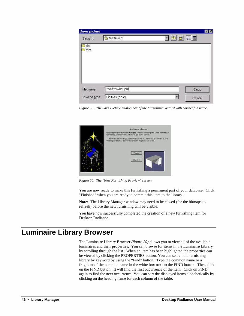
46 • Library Manager Desktop Radiance User Manual
Figure 55. The Save Picture Dialog box of the Furnishing Wizard with correct file name
Figure 56. The "New Furnishing Preview" screen.
You are now ready to make this furnishing a permanent part of your database. Click"Finished" when you are ready to commit this item to the library.
Note: The Library Manager window may need to be closed (for the bitmaps torefresh) before the new furnishing will be visible.
You have now successfully completed the creation of a new furnishing item forDesktop Radiance.
Luminaire Library BrowserThe Luminaire Library Browser (figure 20) allows you to view all of the availableluminaires and their properties. You can browse for items in the Luminaire Libraryby scrolling through the list. When an item has been highlighted the properties canbe viewed by clicking the PROPERTIES button. You can search the furnishinglibrary by keyword by using the “Find” button. Type the common name or afragment of the common name in the white box next to the FIND button. Then clickon the FIND button. It will find the first occurrence of the item. Click on FINDagain to find the next occurrence. You can sort the displayed items alphabetically byclicking on the heading name for each column of the table.
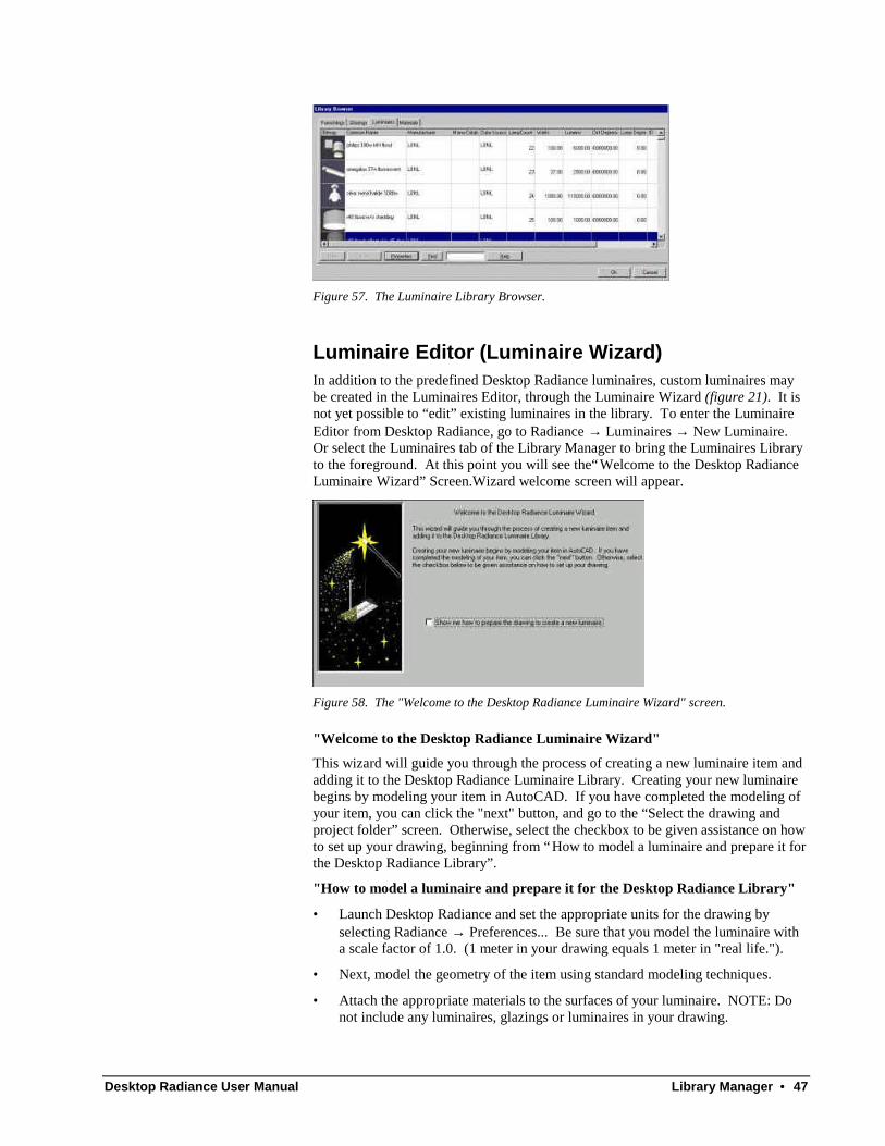
Desktop Radiance User Manual Library Manager • 47
Figure 57. The Luminaire Library Browser.
Luminaire Editor (Luminaire Wizard)In addition to the predefined Desktop Radiance luminaires, custom luminaires maybe created in the Luminaires Editor, through the Luminaire Wizard (figure 21). It isnot yet possible to “edit” existing luminaires in the library. To enter the LuminaireEditor from Desktop Radiance, go to Radiance → Luminaires → New Luminaire.Or select the Luminaires tab of the Library Manager to bring the Luminaires Libraryto the foreground. At this point you will see the“Welcome to the Desktop RadianceLuminaire Wizard” Screen.Wizard welcome screen will appear.
Figure 58. The "Welcome to the Desktop Radiance Luminaire Wizard" screen.
"Welcome to the Desktop Radiance Luminaire Wizard"
This wizard will guide you through the process of creating a new luminaire item andadding it to the Desktop Radiance Luminaire Library. Creating your new luminairebegins by modeling your item in AutoCAD. If you have completed the modeling ofyour item, you can click the "next" button, and go to the “Select the drawing andproject folder” screen. Otherwise, select the checkbox to be given assistance on howto set up your drawing, beginning from “How to model a luminaire and prepare it forthe Desktop Radiance Library”.
"How to model a luminaire and prepare it for the Desktop Radiance Library"
• Launch Desktop Radiance and set the appropriate units for the drawing byselecting Radiance → Preferences... Be sure that you model the luminaire witha scale factor of 1.0. (1 meter in your drawing equals 1 meter in "real life.").
• Next, model the geometry of the item using standard modeling techniques.
• Attach the appropriate materials to the surfaces of your luminaire. NOTE: Donot include any luminaires, glazings or luminaires in your drawing.
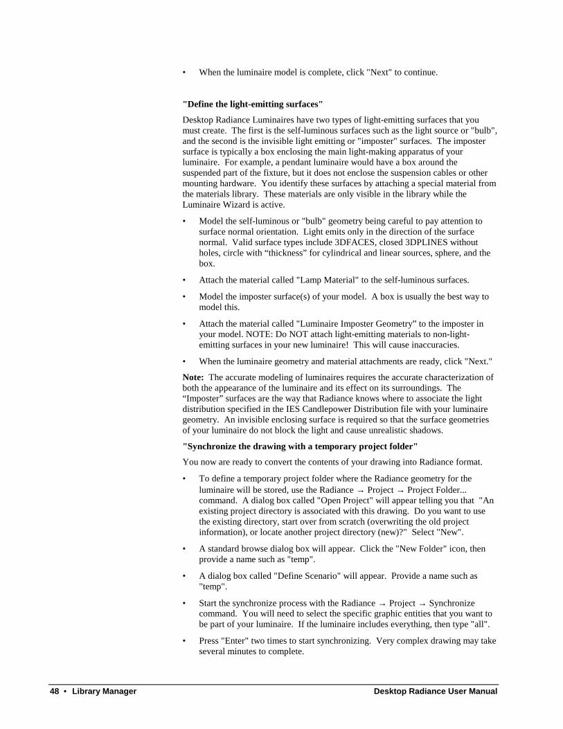
48 • Library Manager Desktop Radiance User Manual
• When the luminaire model is complete, click "Next" to continue.
"Define the light-emitting surfaces"
Desktop Radiance Luminaires have two types of light-emitting surfaces that youmust create. The first is the self-luminous surfaces such as the light source or "bulb",and the second is the invisible light emitting or "imposter" surfaces. The impostersurface is typically a box enclosing the main light-making apparatus of yourluminaire. For example, a pendant luminaire would have a box around thesuspended part of the fixture, but it does not enclose the suspension cables or othermounting hardware. You identify these surfaces by attaching a special material fromthe materials library. These materials are only visible in the library while theLuminaire Wizard is active.
• Model the self-luminous or "bulb" geometry being careful to pay attention tosurface normal orientation. Light emits only in the direction of the surfacenormal. Valid surface types include 3DFACES, closed 3DPLINES withoutholes, circle with “thickness” for cylindrical and linear sources, sphere, and thebox.
• Attach the material called "Lamp Material" to the self-luminous surfaces.
• Model the imposter surface(s) of your model. A box is usually the best way tomodel this.
• Attach the material called "Luminaire Imposter Geometry” to the imposter inyour model. NOTE: Do NOT attach light-emitting materials to non-light-emitting surfaces in your new luminaire! This will cause inaccuracies.
• When the luminaire geometry and material attachments are ready, click "Next."
Note: The accurate modeling of luminaires requires the accurate characterization ofboth the appearance of the luminaire and its effect on its surroundings. The“Imposter” surfaces are the way that Radiance knows where to associate the lightdistribution specified in the IES Candlepower Distribution file with your luminairegeometry. An invisible enclosing surface is required so that the surface geometriesof your luminaire do not block the light and cause unrealistic shadows.
"Synchronize the drawing with a temporary project folder"
You now are ready to convert the contents of your drawing into Radiance format.
• To define a temporary project folder where the Radiance geometry for theluminaire will be stored, use the Radiance → Project → Project Folder...command. A dialog box called "Open Project" will appear telling you that "Anexisting project directory is associated with this drawing. Do you want to usethe existing directory, start over from scratch (overwriting the old projectinformation), or locate another project directory (new)?" Select "New".
• A standard browse dialog box will appear. Click the "New Folder" icon, thenprovide a name such as "temp".
• A dialog box called "Define Scenario" will appear. Provide a name such as"temp".
• Start the synchronize process with the Radiance → Project → Synchronizecommand. You will need to select the specific graphic entities that you want tobe part of your luminaire. If the luminaire includes everything, then type "all".
• Press "Enter" two times to start synchronizing. Very complex drawing may takeseveral minutes to complete.

Desktop Radiance User Manual Library Manager • 49
• When the synchronization process is complete, click "Next" to continue.
"Select the drawing and project folder"
Figure 59. The "Select the Drawing and Project Folder" screen.
At this point we assume that you have already modeled the new luminaire item andsynchronized your drawing. If the drawing is not ready, please click the "back"button to be guided through this process.
• Please specify the drawing name and project folder (figure 22).
"Describe your new luminaire”
Figure 60. The "Describe Your New Luminaire" screen.
• The luminaire manufacturer, model name or number, and item description willhelp you identify this luminaire item in the library browser. If the manufacturername is not in the list, you can click the "New Manufacturer..." button to definea new manufacturer name.
• Provide the information specified below, then click "Next" to continue (figure23).
"Specify the drawing units”
Desktop Radiance needs to know the units (meters/inches) used for the glazing sothat it is properly scaled when inserted into a new drawing. You may havepreviously specified in the Radiance → Preferences... dialog box.

50 • Library Manager Desktop Radiance User Manual
"Specify the Luminaire Distribution”
Figure 61. The "Specify the Luminaire Distribution" Screen.
Desktop Radiance needs to know how the light is distributed from this luminaire.This information is provided by luminaire manufacturers for most commercial/officetype luminaires. The candlepower distribution curve for the luminaire is usuallyprovided in the IESNA format. Please select the IES file, then click "Next" tocontinue (figure 24).
"New Luminaire Preview"
Figure 62. The "New Luminaire Preview" Screen.
Click the preview button (figure 25) to start Winrview and to inspect/preview yournew luminaire item before committing it to the library. To create the preview image,use the File → Save as... command of Winrview to save the image. The defaultname oct_V1.pic needs to be changed to reflect the actual name of your item(Figure 63) and (Figure 64) . In this example, the drawing name is testlumwiz1 so

Desktop Radiance User Manual Library Manager • 51
the image name has to be testlumwiz1.pic.
Figure 63. The Save Picture Dialog box of the Luminaire Wizard with default file name
Figure 64. The Save Picture Dialog box of the Luminaire Wizard with Correct file name
You are now ready to make this luminaire a permanent part of your database. Click"Finished" when you are ready to commit this item to the library.
Note: The Library Manager window may need to be closed (for the bitmaps torefresh) before the new glazing will be visible.

52 • Simulation Manager Desktop Radiance User Manual
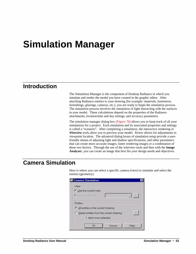
Desktop Radiance User Manual Simulation Manager • 53
Simulation Manager
IntroductionThe Simulation Manager is the component of Desktop Radiance in which yousimulate and render the model you have created in the graphic editor. Afterattaching Radiance entities to your drawing (for example: materials, luminaires,furnishings, glazings, cameras, etc.), you are ready to begin the simulation process.The simulation process involves the simulation of light interacting with the surfacesin your model. These calculations depend on the properties of the Radianceattachments, location/time and day settings, and accuracy parameters.
The simulation manager dialog box (Figure 76) allows you to keep track of all yoursimulations for a project. Each simulation and its associated properties and settingsis called a “scenario”. After completing a simulation, the interactive rendering orWinrview tools allow you to preview your model. Rview allows for adjustments toviewpoint location. The advanced dialog boxes of simulation setup provide a user-friendly means of adjusting light and shadow specifications, and other parametersthat can create more accurate images, faster rendering images or a combination ofthese two factors. Through the use of the winrview tools and then with the ImageAnalyzer, you can create an image that best fits your design needs and objectives.
Camera SimulationHere is where you can select a specific camera (view) to simulate and select theentities (geometry).

54 • Simulation Manager Desktop Radiance User Manual
Figure 65. The Camera Simulation Dialog Box
More text to go here.
Reference Point SimulationHere is where you can select the reference point to simulate and specify the entities(geometry) for including in the simulation.
Figure 66. The Reference Point Simulation Dialog Box
More text go here.
Reference Grid SimulationHere is where you can select the reference grid to simulate and specify the entities(geometry) for including in the simulation.
Figure 67. The Reference Grid Simulation Dialog Box
More text to go here.
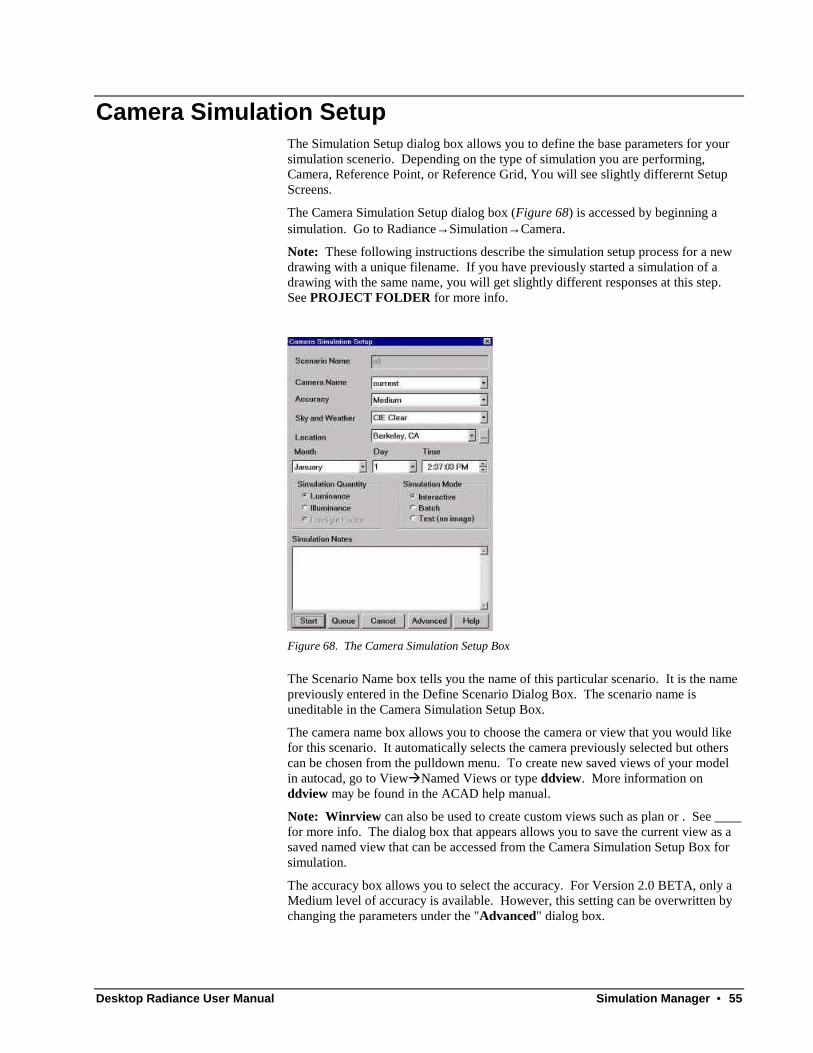
Desktop Radiance User Manual Simulation Manager • 55
Camera Simulation SetupThe Simulation Setup dialog box allows you to define the base parameters for yoursimulation scenerio. Depending on the type of simulation you are performing,Camera, Reference Point, or Reference Grid, You will see slightly differernt SetupScreens.
The Camera Simulation Setup dialog box (Figure 68) is accessed by beginning asimulation. Go to Radiance→ Simulation→ Camera.
Note: These following instructions describe the simulation setup process for a newdrawing with a unique filename. If you have previously started a simulation of adrawing with the same name, you will get slightly different responses at this step.See PROJECT FOLDER for more info.
Figure 68. The Camera Simulation Setup Box
The Scenario Name box tells you the name of this particular scenario. It is the namepreviously entered in the Define Scenario Dialog Box. The scenario name isuneditable in the Camera Simulation Setup Box.
The camera name box allows you to choose the camera or view that you would likefor this scenario. It automatically selects the camera previously selected but otherscan be chosen from the pulldown menu. To create new saved views of your modelin autocad, go to ViewàNamed Views or type ddview. More information onddview may be found in the ACAD help manual.
Note: Winrview can also be used to create custom views such as plan or . See ____for more info. The dialog box that appears allows you to save the current view as asaved named view that can be accessed from the Camera Simulation Setup Box forsimulation.
The accuracy box allows you to select the accuracy. For Version 2.0 BETA, only aMedium level of accuracy is available. However, this setting can be overwritten bychanging the parameters under the "Advanced" dialog box.
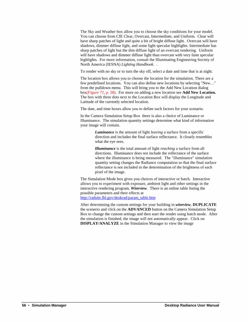
56 • Simulation Manager Desktop Radiance User Manual
The Sky and Weather box allow you to choose the sky conditions for your model.You can choose from CIE Clear, Overcast, Intermediate, and Uniform. Clear willhave sharp patches of light and quite a bit of bright diffuse light. Overcast will haveshadows, dimmer diffuse light, and some light specular highlights. Intermediate hassharp patches of light but the dim diffuse light of an overcast rendering. Uniformwill have shadows and dimmer diffuse light than overcast with very faint specularhighlights. For more information, consult the Illuminating Engineering Society ofNorth America (IESNA) Lighting Handbook. .
To render with no sky or to turn the sky off, select a date and time that is at night.
The location box allows you to choose the location for the simulation. There are afew predefined locations. You can also define new locations by selecting "New… "from the pulldown menu. This will bring you to the Add New Location dialogbox(Figure 71, p. 58). For more on adding a new location see Add New Location.The box with three dots next to the Location Box will display the Longitude andLatitude of the currently selected location.
The date, and time boxes allow you to define such factors for your scenario.
In the Camera Simulation Setup Box there is also a choice of Luminance orIlluminance. The simulation quantity settings determine what kind of informationyour image will contain.
Luminance is the amount of light leaving a surface from a specificdirection and includes the final surface reflectance. It closely resembleswhat the eye sees.
Illuminance is the total amount of light reaching a surface from alldirections. Illuminance does not include the reflectance of the surfacewhere the illuminance is being measured. The "illuminance" simulationquantity setting changes the Radiance computation so that the final surfacereflectance is not included in the determination of the brightness of eachpixel of the image.
The Simulation Mode box gives you choices of interactive or batch. Interactiveallows you to experiment with exposure, ambient light and other settings in theinteractive rendering program, Winrview. There is an online table listing thepossible parameters and their effects athttp://radsite.lbl.gov/deskrad/param_table.htm
After determining the custom settings for your building in winrview, DUPLICATEthe scenerio and click on the ADVANCED button on the Camera Simulation SetupBox to change the custom settings and then start the render using batch mode. Afterthe simulation is finished, the image will not automatically appear. Click onDISPLAY/ANALYZE in the Simulation Manager to view the image

Desktop Radiance User Manual Simulation Manager • 57
Reference Point Calculation Setup
Figure 69. The Reference Point Calculation Setup Dialog Box
More text here.
Reference Grid Calculation Setup
Figure 70. The Reference Grid Calculation Setup Dialog Box
More text to go here.
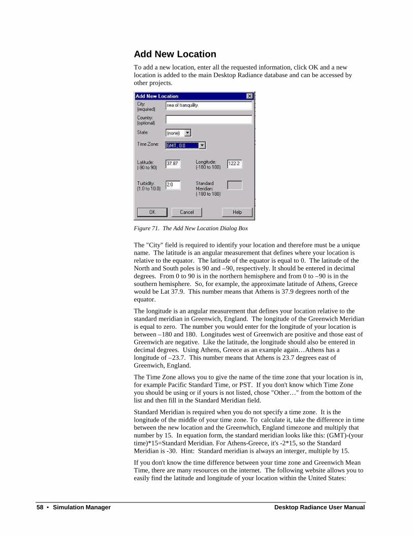
58 • Simulation Manager Desktop Radiance User Manual
Add New LocationTo add a new location, enter all the requested information, click OK and a newlocation is added to the main Desktop Radiance database and can be accessed byother projects.
Figure 71. The Add New Location Dialog Box
The "City" field is required to identify your location and therefore must be a uniquename. The latitude is an angular measurement that defines where your location isrelative to the equator. The latitude of the equator is equal to 0. The latitude of theNorth and South poles is 90 and –90, respectively. It should be entered in decimaldegrees. From 0 to 90 is in the northern hemisphere and from 0 to –90 is in thesouthern hemisphere. So, for example, the approximate latitude of Athens, Greecewould be Lat 37.9. This number means that Athens is 37.9 degrees north of theequator.
The longitude is an angular measurement that defines your location relative to thestandard meridian in Greenwich, England. The longitude of the Greenwich Meridianis equal to zero. The number you would enter for the longitude of your location isbetween –180 and 180. Longitudes west of Greenwich are positive and those east ofGreenwich are negative. Like the latitude, the longitude should also be entered indecimal degrees. Using Athens, Greece as an example again… Athens has alongitude of –23.7. This number means that Athens is 23.7 degrees east ofGreenwich, England.
The Time Zone allows you to give the name of the time zone that your location is in,for example Pacific Standard Time, or PST. If you don't know which Time Zoneyou should be using or if yours is not listed, chose "Other… " from the bottom of thelist and then fill in the Standard Meridian field.
Standard Meridian is required when you do not specify a time zone. It is thelongitude of the middle of your time zone. To calculate it, take the difference in timebetween the new location and the Greenwhich, England timezone and multiply thatnumber by 15. In equation form, the standard meridian looks like this: (GMT)-(yourtime)*15=Standard Meridian. For Athens-Greece, it's -2*15, so the StandardMeridian is -30. Hint: Standard meridian is always an interger, multiple by 15.
If you don't know the time difference between your time zone and Greenwich MeanTime, there are many resources on the internet. The following website allows you toeasily find the latitude and longitude of your location within the United States:

Desktop Radiance User Manual Simulation Manager • 59
http://www.census.gov/cgi-bin/gazetteer
If your location is not in the United States then you can visit the following website tofind the latitude and longitude of your location, click on the "Access GEOnet"button:
http://www.nima.mil/gns/html/
The turbidity factor corresponds to atmospheric scattering. A turbidity factor of 1.0indicates an ideal clear atmosphere (i.e. a completely dark sky). Values less than 1.0are physically impossible. The CIE standard value for Turbidity is 2.0 (very clearsky) and the maxium is 6.0 (very hazy, polluted sky). Unfortunately there is verylittle data available for sky turbidity.
Advanced Calculation PropertiesThe Advanced Calculation Properties dialog boxes (Figure 72, Figure 73, Figure 74,and Figure 75) are a series of settings under the main categories of Analysis,Lighting, Geometry, and Rendering. They are most commonly used in the final stepsof creating a highly accurate, high quality rendering. To access these dialog boxesclick ADVANCED on the Simulation Setup dialog box. Many of these settings arealso found in the interactive rendering program, winrview. The settings in winrvieware intended to allow the user to quickly and easily test different values and settings.When ideal settings are found, then the user can make the changes in the AdvancedCalculation Properties dialog boxes which will save the setting with the scenario.After making changes in the Advaned Calculation Properties dialog boxes a highquality batch mode simulation can be made by selecting batch on the simulationsetup dialog box.
The tab of the Advanced Calculation Parameters dialog box (Figure 72) includessettings that can help with the analysis of images created in a Radiance simulations.
Figure 72. The Advanced Tab of the Calculation Parameters "Analysis" Dialog Box

60 • Simulation Manager Desktop Radiance User Manual
The settings in the Image Exposure section affect how light/dark your image willappear. By selecting Auto (linear average), the exposure will automatically be set to1.0. This is a good exposure starting point. If you have a specific value or you wantthe image to be darker or lighter than usual, then use the absolute settings or therelative f-stop settings.
The "Use Custom Post-processing Settings" checkbox refers to whether you areusing a PFILT setting other than the default. If you are using a different value thenthis box should be checked.
The Save Z-buffer data check box allows you to store in the specified file thedistance from the image plane to the ray intersection point in the scene. This file canbe used to improve the rendering time of animations, but this is not currentlysupported by Desktop Radiance.
TheLighting tab of the Advanced Calculation Parameters dialog box (Figure 73)allows you to control various settings that have to do with how light will besimulated in your model.
Figure 73. The Lighting Tab of the Advanced Calculation Parameters Dialog Box
Ambient bounces sets the number of times light is required to bounce from surface tosurface before finding a light source such as the sun, the sky, or a luminaire. Thelower the number, the faster the calculation but you may not be including all of theambient light in your scene. At the last bounce of light, a constant backgroundambient value is added to the computation as specified in the Ambient Value box. Areasonable number to use is anywhere between 1 and 5.
If you plan to compute many renderings of the same 3D model, you can check the“keep ambient data” button and apply the name of a file to store the indirect lighting

Desktop Radiance User Manual Simulation Manager • 61
calculation. This will allow subsequent simulations to compute much more quickly.However, make sure that all geometry, sky, and lighting parameters remain constantfor any given ambient data file.
If your scene has complex glazings or fenestrations, you can select to “Performglazing pre-calculation”. This causes Radiance to initiate a pre-calculation of thedistribution of light through your complex glazing or fenestration system. By default,all Desktop Radiance glazings are identified as potential complex glazing surfaces.Un-checking this box disables the pre-calculations and will result in a fastercalculation.
The glazing accuracy field sets overall accuracy and calculation requirements of theglazing pre-calculation. This field is currently set to medium accuracy only. Youcan provide more accurate pre-calculation parameters in the mkillum options field.See Mkillum at http://radsite.lbl.gov/radiance/man_html/mkillum.1.html for moreinformation.
The Geometry Tab of the Advanced Calculation Parameters Dialog Box (Figure 74)deals with various settings related to the 3-dimensional geometry of your scene.
Figure 74. The Geometry Tab of the Advanced Calculation Parameters Dialog Box
A zone is a volume of space that indicates where you intend to focus the simulationon. The Zone is an optional parameter. The default zone encompasses the entirescene. To increase the accuracy of your simulation, define a zone whichencompasses the smallest contiguous volume of space in which you intend toperform lighting simulations. For example, if you have an expansive model of ahigh-rise office building but you are mainly interested in the left corner cubicle onthe 5th floor, you should define a zone which encompasses only the cubicle area byusing the Radiance → Analysis → Define Zone command within the graphic editor.The name of the zone you create will appear in the Zone Name field. The 6 pointdefinition boxes (Xmin, Xmax, Ymin… ) are the dimensions of the selected zone. If

62 • Simulation Manager Desktop Radiance User Manual
your scene is predominately composed of small geometric entities relative to theoverall size of the scene, then the Geometric Detail setting can be used to improvethe accuracy of your simulations. Medium is the default setting and is suitable formost situations. A low geometric detail setting may speed up the simulation process,but the accuracy may be reduced.
The octree file specifies the name of the intermediate scene geometry file used forincreasing the speed of the ray-tracing calculations. This value changes with thename of your scenerio necessitating the re-generation of the octree for each scenario.If your geometry has not changed from a previous scenerio, you can replace thedisplayed filename with the octree file from the other scenerio that you would like touse For more information on the octree settings, seehttp://radsite.lbl.gov/radiance/man_html/oconv.1.html.
The three selections below the octree settings box allow you to control howfrequently the intermeidate scene geometry file is rgenerated. Usualy the octree isregenerated only once the first time the scenario is simulated, regardless of whetherthe geometry from the drawing changes. The “Regenerate Octree When GeometryChange” choice allows changes from your drawing to be carried forward intosebsequent duplicated scenario. “Always Regenerate Octree” will force the octree tobe regenerated everytime the simulation is started even if no geometry has changed.
The Rendering Tab of the Advanced Calculation Parameters Dialog Box (Figure 75)determines the pictorial quality of the simulation image rendering from yourRadiance model.
Figure 75. The Rendering Tab of the Advanced Calculation Parameters Dialog Box
The RIF Control File box shows the name of the scenerio you are dealing with. Thisvalue is determined by the scenario name and can't be changed here.
Desktop Radiance User Manual Simulation Manager • 63
Rendering quality sets the overall quality of the simulation. With the soft shadowsbox checked, penumbras will be rendered so that shadow edges are blurred whenilluminated by non-point source lights. . Rendering time will be significantly longerwith this option enabled.
Final resolution determines the horizontal and vertical pixel count of the renderedimage. If the image is not square or if you do not know the exact size you wouldlike, you may supply just the horizontal size and the program will figure out thevertical for you.
Usually Desktop Radiance filters the initial rendering to determine the averageexposure and to perform any image sampling to reduse jagged lines and deletes the“raw” original image file. However, if you would like to perform animations or ifyou would like to be able to recover a very large image that has crashed for somereason, then the raw image needs to be preserved. Oversample Ratio allows you toreduce aliasing and jagged lines in your image. By increasing this value, lines willbecome smoother. Increasing this value increases rendering time proportional to theproduct of the two resolution values. Increasing the oversample from 1x to 2x willincrease rendering time by 4 times.
If you would like to preserve a history of the ray-tracing process for later analysis orto determine possible causes of a failed simulation, then you can select the “save JobReport Log” and provide the log file name. The “Report Interval” field determineshow often the log file is updated with the rendering process.
High Quality RenderingsBefore creating a high quality rendering, it is best to validate your scenario in theinteractive rendering program winview. To do this, simply render your image in theInteractive Mode. This is the default mode setting in the Simulation Setup DialogBox. Once you are satisfied with the geometry, views, materials, and all otheraspects of your model, it is ready to start a high quality rendering. In the SimulationManager dialog box select the scenario that you would like to become a high quality.Click “duplicate” and provide a new scenario name. Once the Simulation SetupDialog Box appears select Batch as the mode choice. A batch rendering allows youto render the image of your model at a far greater resolution than your monitorresolution. Click the ADVANCED button in the Simulation Setup dialog box andselect the RENDERING tab. First select High or Medium quality for your rendering.Then enter the final resolution that you would like. Next, select the amount of oversampling that you would like. Over sampling reduces the "jaggies". Although becareful with this setting, each incremental increase of over sampling can quadrupleyour rendering time. A fairly high quality rendering can be created by increasingthe oversampling ratio to 2x, on the “lighting” tab set the light variability to “high”,on the “geometry tab set the geometric detail to “high”. If the above settings do notresult in a high enough quality, then try setting rendering quality on the “rendering”tab to “high”.
Simulation ManagerThe Simulation Manager provides you with tools to manage your scenarios. All ofthe properties and settings of your simulation are associated with a scenario. Eachscenario is represented on a separate row of the simulation manager dialog box grid.

64 • Simulation Manager Desktop Radiance User Manual
Figure 76. The Simulation Manager dialog box
The START button will begin a simulation that you have highlighted from the list.The DUPLICATE button allows you to duplicate a highlighted scenario and changesettings on the Simulation Setup Dialog Box. MOVE UP and MOVE DOWN willchange the order of the scenarios. DELETE will delete the highlighted scenario.CLOSE closes the Simulation Manager dialog box. After your rendering is finishedand saved, the Display/Analyze button can be used to launch Winimage, the imageanalyzer. For more information, see Image Analyzer.
The columns of the Simulation Manager grid include:
• Scenario Name – the name you specified in the Graphic Editor whenyou started the simulation
• Simulation Type – Camera, Reference Point or Reference Gridsimulation
• Camera/Reference – the name of the Camera, Reference Point orReference Grid you selected when you set up the simulation. Thiscolumn will show "current" if you did not select a specific camera, butinstead used the currently active view displayed in the Graphic Editor.
• Simulation Mode – interactive, batch, or test simulation
• Simulation Quantity – luminance or illuminance
• % Done – currently either Ready, In Progress, or Done
• Accuracy – currently only Medium is provided
• Sky Type – CIE Clear, CIE Intermediate, CIE Overcast, or Uniformsky
• Location – The name of the location specified in the Simulation Setupdialog box
• North Arrow – The name of the orientation North Arrow you selectedin the Simulation Setup Advanced dialog box, geometry tab
• Month – The month of the year on which the simulation will beperformed
• Day – The day of the month on which the simulation will be performed
• Time – The time of day on which the simulation will be performed
• Zone – The name of the Zone created in the Graphic Editor for thissimulation
Desktop Radiance User Manual Simulation Manager • 65
• RIF File Name – The name of the Radiance Input File that is createdby the Simulation Manager for each scenario. This file can be found inthe project folder for the current drawing.
• Preprocess – The name of the Preprocess command file that is createdby Desktop Radiance to pre-compute the intermediate octree file forblock entities inside your drawing.
• Simmode String – This field is controlled by the Simulation Manager.It displays the command-line options for the rad command that will beused to start this simulation based on the parameters you specified.
Project FolderAll geometry, properties and settings of your scenarios are stored in a commonproject folder. The project folder is automatically created when you start your firstsimulation. The default project folder is located in the installation directory forDesktop Radiance (usually C:\Program Files\Desktop Radiance) in a sub-folder withthe same name as the drawing. You can change this directory or re-connect yourdrawing with a project folder that has been moved with the Radiance à Project àProject Folder menu command. You can duplicate the entire project folder keepingall of the simulation data intact with the Radiance à Project à Duplicate Projectcommand. Because the Radiance for Windows rendering engine can not currentlydeal with folder names with the full complexity of characters that Windows allows,you should take care to specify a folder name that only includes alpha-numericcharacters, and the underscore.
If you select a project folder that already contains information from previoussimulations, Desktop Radiance will first attempt to validate that the drawing and thesimulations found in the specified folder match. Desktop Radiance will first checkto see if a project database (DRADMAIN.MDB) exists in the specified projectfolder, and if so it will compare the unique project identification number of theDrawing with the project identification number stored in the project database. If theproject identification numbers do not match, you will not be allowed to use thespecified project folder. In earlier versions of Desktop Radiance (1.02 and earlier) itwas possible to override the fact the project identification numbers did not match.This behavior has been changed to prevent the possible loss or corruption ofinformation that can occur if the drawing and database are not an appropriate match.
If the drawing which you want to start the simulation and rendering of conflicts withthe name of another project and/or drawing, you will be prompted with the ProjectDatabase Conflict Dialog box (Figure 77, p. 66). If Use Existing is selected, theinformation in the existing project folder will be used and new information added tothe existing project database. Information will not be overwritten, but if significantchanges have been made, overwriting the project may be recommanded. If New isselected, you may be prompted by another dialog box to locate and create the newdirectory (Figure 78, p. 66).
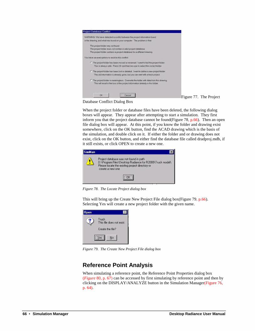
66 • Simulation Manager Desktop Radiance User Manual
Figure 77. The ProjectDatabase Conflict Dialog Box
When the project folder or database files have been deleted, the following dialogboxes will appear. They appear after attempting to start a simulation. They firstinform you that the project database cannot be found(Figure 78, p.66). Then an openfile dialog box will appear. At this point, if you know the folder and drawing existsomewhere, click on the OK button, find the ACAD drawing which is the basis ofthe simulation, and double click on it. If either the folder and or drawing does notexist, click on the OK button, and either find the database file called dradproj.mdb, ifit still exists, or click OPEN to create a new one.
Figure 78. The Locate Project dialog box
This will bring up the Create New Project File dialog box(Figure 79, p.66).Selecting Yes will create a new project folder with the given name.
Figure 79. The Create New Project File dialog box
Reference Point AnalysisWhen simulating a reference point, the Reference Point Properties dialog box(Figure 80, p. 67) can be accessed by first simulating by reference point and then byclicking on the DISPLAY/ANALYZE button in the Simulation Manager(Figure 76,p. 64).
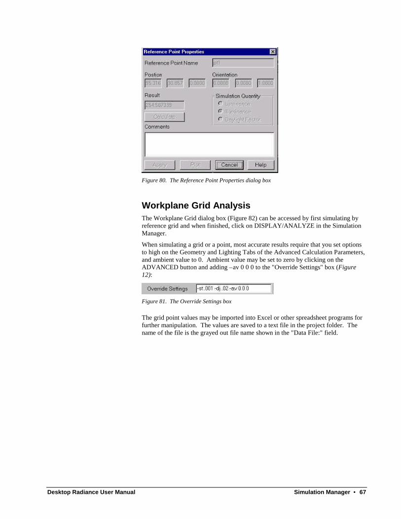
Desktop Radiance User Manual Simulation Manager • 67
Figure 80. The Reference Point Properties dialog box
Workplane Grid AnalysisThe Workplane Grid dialog box (Figure 82) can be accessed by first simulating byreference grid and when finished, click on DISPLAY/ANALYZE in the SimulationManager.
When simulating a grid or a point, most accurate results require that you set optionsto high on the Geometry and Lighting Tabs of the Advanced Calculation Parameters,and ambient value to 0. Ambient value may be set to zero by clicking on theADVANCED button and adding –av 0 0 0 to the "Override Settings" box (Figure12):
Figure 81. The Override Settings box
The grid point values may be imported into Excel or other spreadsheet programs forfurther manipulation. The values are saved to a text file in the project folder. Thename of the file is the grayed out file name shown in the "Data File:" field.
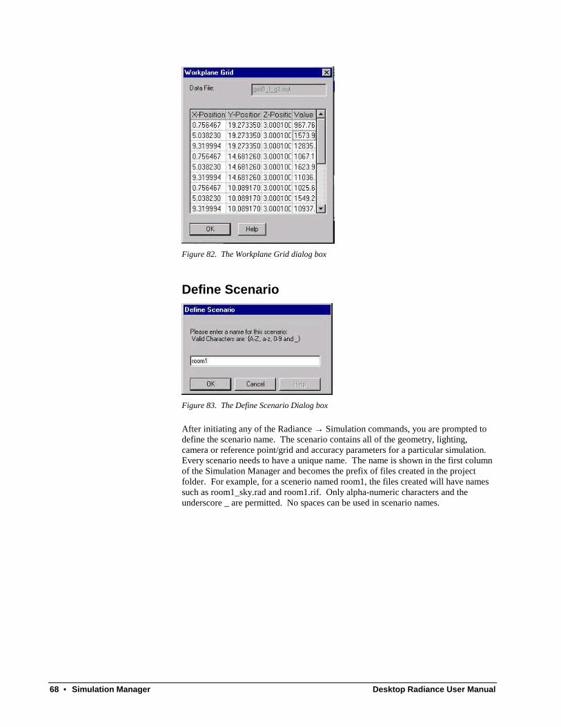
68 • Simulation Manager Desktop Radiance User Manual
Figure 82. The Workplane Grid dialog box
Define Scenario
Figure 83. The Define Scenario Dialog box
After initiating any of the Radiance → Simulation commands, you are prompted todefine the scenario name. The scenario contains all of the geometry, lighting,camera or reference point/grid and accuracy parameters for a particular simulation.Every scenario needs to have a unique name. The name is shown in the first columnof the Simulation Manager and becomes the prefix of files created in the projectfolder. For example, for a scenerio named room1, the files created will have namessuch as room1_sky.rad and room1.rif. Only alpha-numeric characters and theunderscore _ are permitted. No spaces can be used in scenario names.

Desktop Radiance User Manual Image Analyzer • 69

70 • Image Analyzer Desktop Radiance User Manual
Image Analyzer
IntroductionThe Image Analyzer (Error! Reference source not found.), also known asWinimage, may be opened from within Desktop Radiance with theRadiance→ Tools→ Image Analyzer menu, or by clicking on the Image Analyzericon created by the install program in the start menu.
Figure 84. The Image Analyzer Dialog Box
The Image Analyzer displays Radiance images and provides you with tools toperfrom various analyses and image manipulations. Radiance images are saved withthe default extension .pic. You may also convert images with the File → Save As…command so they can be read by other imaging, paint, or presentation programs.All commands operating within winimage, with the exception of redraw, will resultin a new image file being created in your project folder. This is so the differentversions of the image will be distinguishable.
A file naming convention in Winimage is adding “_” and an abbreviation of theexecuted command, i .e. “fls” for falsecolor. Thus, if falsecolor is performed on
Desktop Radiance User Manual Image Analyzer • 71
drawing.pic, the resulting falsecolor image will be drawing_fls.pic. If an annotationis performed on drawing_fls.pic, then the resulting image will bedrawing_fls_ann.pic. The original drawing.pic is not overwritten. However, iffalsecolor is performed on the same image twice, the second version will overwritethe earlier one.
Here is a list of possible file extensions and their meanings.
_avg = Image → Exposure → Image
_reg = Image → Exposure → Region (drag mouse to enclose a rectangular area)
_pt = Image → Exposure → Point (click on a point in scene)
_90 = Image → Rotate → 90 degrees clockwise
_180 = Image → Rotate → 180
_fh = Image → Flip → Horizontal
_fv = Image → Flip → Vertical
_pcd = Analysis → Human Sensitivity → Image
_fls = Analysis → FalseColor or Analysis → IsoContour
_ann = Analysis → Annotate
The Radiance RGBE FormatAn important advantage of the Radiance Synthetic Imaging System is the highdynamic range provided by its RGBE image file format. It allows for storing real-world luminance and illuminance values across 77 orders of magnitude with 1%accuracy.
Images can contain either scalar data (which lacks the high dynamic range), orluminance/illuminance values. It is important to distinguish between those twoformats because scalar images are not appropriate for analysis as they lack the real-world high dynamic range values.
Scalar images result from the use of any of the commands under the Analysis menu.
High dynamic range images result from the use of any of the commands under the“image” menu. A scalar image cannot be converted backto a high dynamic image.
Luminance vs Illuminance ImagesRadiance image files can contain either radiance (luminance) or irradiance(illuminance) values. Unfortunately, Winimage currently does not distinguishbetween these two different types. It is therefore possible to perform operations andlabel images in a manner inconsistant with the underlying data stored in the imagefile. It is incombent upon the user to ensure that the appropriate quantities areanalyzed and displayed.

72 • Image Analyzer Desktop Radiance User Manual
File
OpenImage Analyzer will only open Radiance .pic images for viewing and analysis. Itwill not open pictures or images saved in other file formats.
Save AsA Radiance image may be saved as a pic, gif, tiff, pct (mac pict file), eps, or bmp.The saved image, if in a format other than Radiance’s .pic, will not be openable bywinimage again.
ImageThe functions available under the Image menu result in new images which preservethe real-world, high dynamic range of the original image. Such images are suitablefor later manipulations with functions under the analysis menu. You can printimages by opening one of these files in a print program.
RedrawImage Analyzer→ Image→ Redraw, this function redraws/regenerates your image. Itdoes not create a new drawing.
ExposureImage Analyzer→ Image→ Exposure, this tool adjusts the exposure level of theselected image, region, or point using a linear function with clamping. The adjustedimage will be given a name with the extension *_pt.pic and saved as a new .pic fileautomatically as it is being displayed. This is similar to how a camera works and canonly partially compensate for regions of the image which are too bright or too dark.The sky seen outside of windows, for example, will appear completely white if theimage is exposed for the interior surfaces.
Image
Image Analyzer→ Image→ Exposure→ Image. This tool adjusts the exposure byaveraging all pixels of the image displayed in the foreground.
Region
Image Analyzer→ Image→ Exposure→ Region, then select the region by clicking anddragging. This tool averages the image displayed in the foreground based upon theaverage value of a selected region. If the image has a washed-out or brightly litwindow and a room’s interior, the window may be selected for exposing. Theresulting new image will be of a dimmer interior and a window which seems lessbright.
Point
Image Analyzer→ Image→ Exposure→ Point, then select a point on the image withthe cursor. This tool adjusts the exposure relative to the point you have selected.

Desktop Radiance User Manual Image Analyzer • 73
RotateImage Analyzer→ Image→ Rotate. This tool rotates the image either 90 degreesclockwise or 180 degrees. It is sometimes necessary to rotate plan view images sothat the desired orientation of the image with respect to the top of the page isachieved.
FlipImage Analyzer→ Image→ Flip. This tool will flip (mirror) the image horizontally orvertically. This is useful for creating reflected ceiling plans from parallel projectionimage looking “up” at the ceiling.
AnalysisThe functions available under the analysis menu result in new images which lose thereal-world luminance and illuminance values because they contain scalar data, notreal-world luminance or illuminance values. They become unsuitable for furthermanipulations under the analysis menu.
Human SensitivityThis tool is similar to an exposure adjustment but uses a variety of nonlinear andlinear filters to mimic human visual perception. This tool compresses the dynamicrange so that most of the details in a high-contrast image may be displayedsimultaneously, similar to the visual experience one may have in the actual space.(See also Pcond).
Image
Image Analyzer→ Analysis→ Human Sensitivity→ Image. The human sensitivitytool will consider the entire image (Error! Reference source not found., left) todetermine the appropriate perceptual exposure setting. The resulting new image(Error! Reference source not found., right) may take a few minutes to complete,especially for wide-angle views.
Figure 85. Image before (left) and after (right) running Human Sensitivity. Notice thatHuman Sensitivity image shows exterior details that are not visible in the other image.

74 • Image Analyzer Desktop Radiance User Manual
False Color
Figure 86. The Falsecolor Dialog Box
Image Analyzer→ Analysis→ Falsecolor brings up the Falsecolor Dialog Box(Error! Reference source not found.). When applied to a luminance image,falsecolor outputs (Metric) candela/m2 or (English) footlamberts. When applied toan illuminance image, falsecolor outputs lux or footcandle. The number of divisionssets the number of intermediate, equally spaced values between zero and the maxiumvalue that will be displayed on the legend. Show pixel extrema, if selected, willcause falscolor to annotate the image pixel with the max and min luminance orilluminance values (Error! Reference source not found.). Be sure that the selectedquantity matches the underlying image type.
See Luminance vs Illuminance Images.
Figure 87. Falsecolor image with Show Pixel Extrema selected
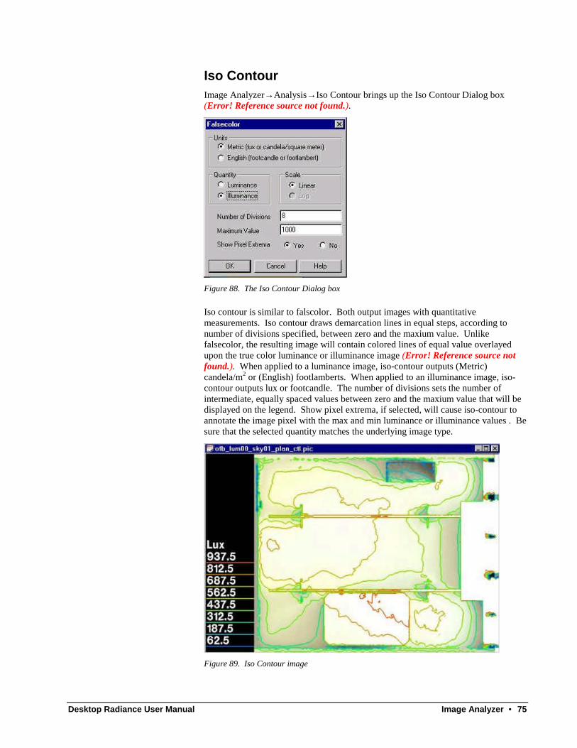
Desktop Radiance User Manual Image Analyzer • 75
Iso ContourImage Analyzer→ Analysis→ Iso Contour brings up the Iso Contour Dialog box(Error! Reference source not found.).
Figure 88. The Iso Contour Dialog box
Iso contour is similar to falscolor. Both output images with quantitativemeasurements. Iso contour draws demarcation lines in equal steps, according tonumber of divisions specified, between zero and the maxium value. Unlikefalsecolor, the resulting image will contain colored lines of equal value overlayedupon the true color luminance or illuminance image (Error! Reference source notfound.). When applied to a luminance image, iso-contour outputs (Metric)candela/m2 or (English) footlamberts. When applied to an illuminance image, iso-contour outputs lux or footcandle. The number of divisions sets the number ofintermediate, equally spaced values between zero and the maxium value that will bedisplayed on the legend. Show pixel extrema, if selected, will cause iso-contour toannotate the image pixel with the max and min luminance or illuminance values . Besure that the selected quantity matches the underlying image type.
Figure 89. Iso Contour image

76 • Image Analyzer Desktop Radiance User Manual
AnnotateImage Analyzer→ Analysis→ Annotate brings up the annotate dialog box. This toolplaces text on image. Type the annotation text in dialog box, press ok, and anupdated image with appear with overlay text.
Window
New WindowImage Analyzer→ Window→ New Window opens another window of the sameimage. This allows different parts of the image to be viewed simultaneously, or fordifferent analyses to be performed and compared side by side.
CascadeImage Analyzer→ Window→ Cascade displays all open images in a cascadingfashion.
TileImage Analyzer→ Window→ Tile tiles all open drawings.
Arrange IconsImage Analyzer→ Window→ Arrange Icons lines up minimized image icons at thebottom of the winimage window.

Desktop Radiance User Manual Interactive Rendering (Winrview) • 77

78 • Interactive Rendering (Winrview) Desktop Radiance User Manual
Interactive Rendering (Winrview)
IntroductionDesktop Radiance allows for real time, interactive rendering. The image pixelsprogressively refine on the screen and start to give you an idea of what the scene willlook like. Winrview is not meant to be a high resolution rendering tool but morefor determining viewpoints and validating scene geometry (make sure windownormals are correct, furniture not floating in midair, walls meet, etc). The winrviewinteractive rendering is the default mode for camera simulations. To produce highquality images, select Batch mode in the Camera Simulation Setup box.
Figure 90. The winrview window during rendering (right) and after rendering (right).
File
Append View to RIF fileThis function saves the current view information as text into a specified .rif file inthe project directory which can be used for a subsequent rendering. A RIF file is notan image and cannot be opened in the Image Analyzer or winrview. But a referenceto the view information saved within a .RIF file may be used in a later rendering orsimulation. This tool suppliments the Define Camera Position command inside ofDesktop Radiance/Graphic Editor. After starting an interactive rendering(winrview), you can use Set → View or the sliders to set up a different view for lateruse. When you are satisfied with the view, goto File → Append View to rif file.You will the see a browser window with RIF files listed (Figure 91).
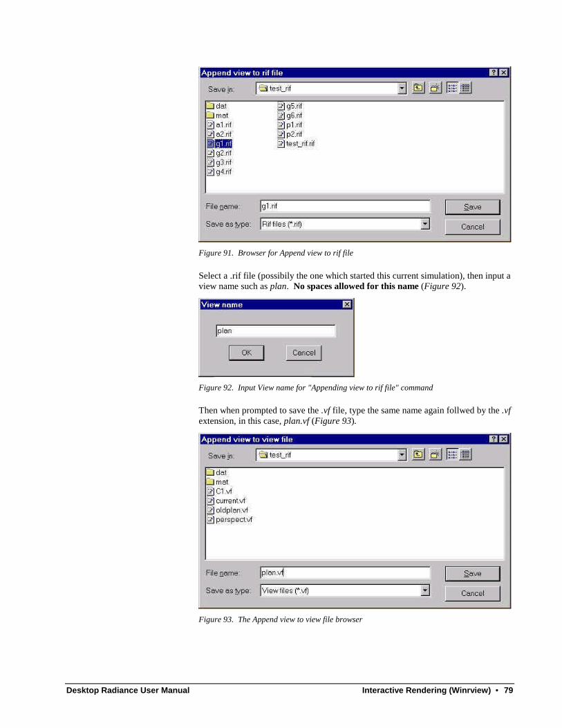
Desktop Radiance User Manual Interactive Rendering (Winrview) • 79
Figure 91. Browser for Append view to rif file
Select a .rif file (possibily the one which started this current simulation), then input aview name such as plan. No spaces allowed for this name (Figure 92).
Figure 92. Input View name for "Appending view to rif file" command
Then when prompted to save the .vf file, type the same name again follwed by the .vfextension, in this case, plan.vf (Figure 93).
Figure 93. The Append view to view file browser
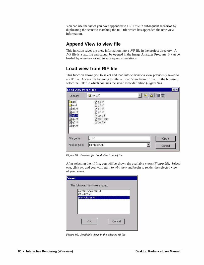
80 • Interactive Rendering (Winrview) Desktop Radiance User Manual
You can use the views you have appended to a RIF file in subsequent scenarios byduplicating the scenario matching the RIF file which has appended the new viewinformation.
Append View to view fileThis function saves the view information into a .VF file in the project directory. A.VF file is a text file and cannot be opened in the Image Analyzer Program. It can beloaded by winrview or rad in subsequent simulations.
Load view from RIF fileThis function allows you to select and load into winrview a view previously saved toa RIF file. Access this by going to File → Load View from rif file. In the browser,select the RIF file which contains the saved view definition (Figure 94).
Figure 94. Browser for Load view from rif file
After selecting the rif file, you will be shown the available views (Figure 95). Selectone, click ok, and you will return to winrview and begin to render the selected viewof your scene.
Figure 95. Available views in the selected rif file
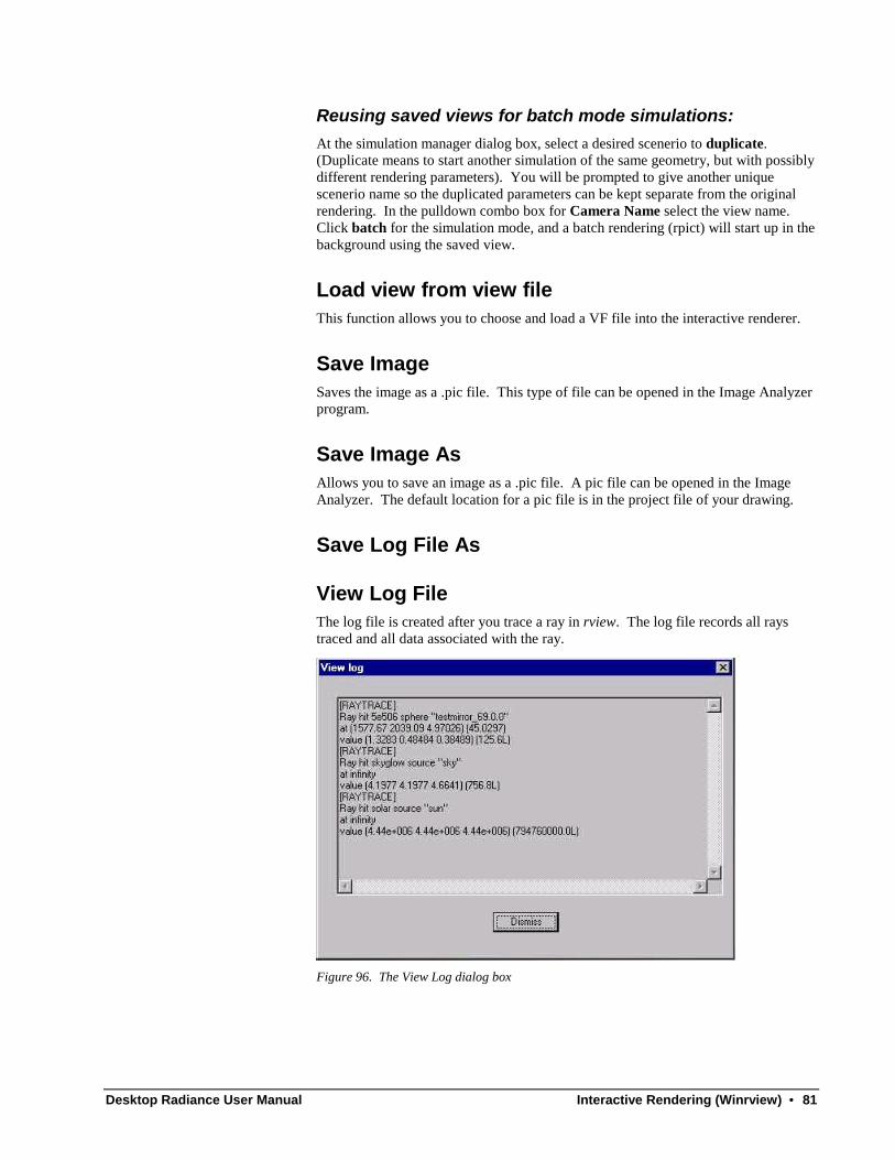
Desktop Radiance User Manual Interactive Rendering (Winrview) • 81
Reusing saved views for batch mode simulations:At the simulation manager dialog box, select a desired scenerio to duplicate.(Duplicate means to start another simulation of the same geometry, but with possiblydifferent rendering parameters). You will be prompted to give another uniquescenerio name so the duplicated parameters can be kept separate from the originalrendering. In the pulldown combo box for Camera Name select the view name.Click batch for the simulation mode, and a batch rendering (rpict) will start up in thebackground using the saved view.
Load view from view fileThis function allows you to choose and load a VF file into the interactive renderer.
Save ImageSaves the image as a .pic file. This type of file can be opened in the Image Analyzerprogram.
Save Image AsAllows you to save an image as a .pic file. A pic file can be opened in the ImageAnalyzer. The default location for a pic file is in the project file of your drawing.
Save Log File As
View Log FileThe log file is created after you trace a ray in rview. The log file records all raystraced and all data associated with the ray.
Figure 96. The View Log dialog box
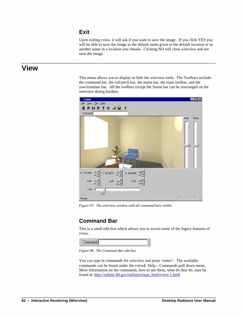
82 • Interactive Rendering (Winrview) Desktop Radiance User Manual
ExitUpon exiting rview, it will ask if you want to save the image. If you click YES youwill be able to save the image as the default name given in the default location or asanother name in a location you choose. Clicking NO will close winrview and notsave the image.
ViewThis menu allows you to display or hide the winrview tools. The Toolbars include:the command bar, the roll/pitch bar, the status bar, the main toolbar, and theyaw/translate bar. All the toolbars except the Status bar can be rearranged on thewinrview dialog borders.
Figure 97. The winrview window with all command bars visible
Command BarThis is a small edit box which allows you to access some of the legacy features ofrview.
Figure 98. The Command Bar edit box
You can type in commands for winrview and press <enter>. The availablecommands can be found under the rview→ Help→ Commands pull down menu.More information on the commands, how to use them, what do they do, may befound at: http://radsite.lbl.gov/radiance/man_html/rview.1.html
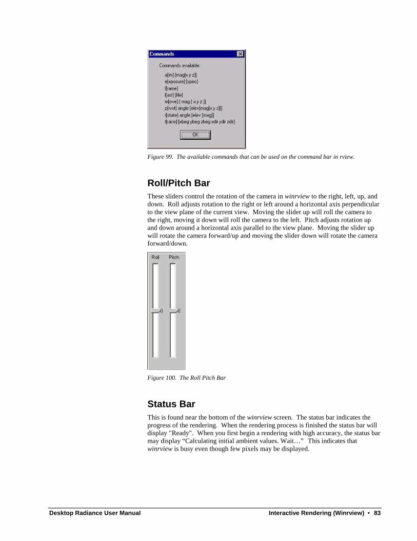
Desktop Radiance User Manual Interactive Rendering (Winrview) • 83
Figure 99. The available commands that can be used on the command bar in rview.
Roll/Pitch BarThese sliders control the rotation of the camera in winrview to the right, left, up, anddown. Roll adjusts rotation to the right or left around a horizontal axis perpendicularto the view plane of the current view. Moving the slider up will roll the camera tothe right, moving it down will roll the camera to the left. Pitch adjusts rotation upand down around a horizontal axis parallel to the view plane. Moving the slider upwill rotate the camera forward/up and moving the slider down will rotate the cameraforward/down.
Figure 100. The Roll Pitch Bar
Status BarThis is found near the bottom of the winrview screen. The status bar indicates theprogress of the rendering. When the rendering process is finished the status bar willdisplay "Ready". When you first begin a rendering with high accuracy, the status barmay display “Calculating initial ambient values. Wait… ” This indicates thatwinrview is busy even though few pixels may be displayed.
84 • Interactive Rendering (Winrview) Desktop Radiance User Manual
Figure 101. The winrview Status Bar
Tool BarThe main toolbar contains six different tools (Figure 102) that are useful informatting your winrview screen to best fit your needs and analysis objectives.
Figure 102. The main toolbar in rview
"E" adjusts the exposure. This effects how light or dark your winrview image is. Formore on this see Exposure.
"F" allows you to frame an area of the winrview image for refinement. For more onthis see Frame.
"N" redraws or regenerates the winrview image. This is sometimes necessary if youhave changed several parameters or settings in rview. For more on this see Redrawsa New image.
"P" allows you to adjust certain image parameters in rview. For more on this seeWinrview Parameters Dialog box.
"T" allows you to ray trace. For more on this see Ray Tracing.
"V" allows you to adjust and set the winrview view. For more on this see Set View.
Yaw and Translate BarThe Yaw tool turns the view about the Z axis to the right or left. Adjusting the Yawslider to a smaller number makes it turn left, and a larger number turns the camera tothe right.

Desktop Radiance User Manual Interactive Rendering (Winrview) • 85
Figure 103. The Yaw and Translate Bar
The X,Y, and Z spinners move your viewpoint position along the X, Y, and Z axes.The larger spinners move the viewpoint in larger increments. The smaller spinnersmove the viewpoint in smaller increments. To adjust the increments that thesespinners set with see GUI Increments.
The spinners labeled F/B, L/R, and U/D move the viewpoint from it's relativeposition and angle, as opposed to along an axis which the X,Y, and Z spinners do.
The F/B spinners move the viewpoint forward and backward. The up pointingspinners move the viewpoint forwards. The down pointing spinners move theviewpoint backwards.
The L/R spinners move the viewpoint to the left and right. The spinner pointing upmoves the viewpoint to the left. The spinner pointing down moves the viewpoint tothe right.
The U/D spinners move the viewpoint up and down. The spinner pointing upmoves the viewpoint up. The spinner pointing down moves the viewpoint down.
SetThis menu item allows you to turn on and off certain features of rview. SET alsoprovides another way of accessing some commands that are found on the mainwinrview toolbar.
Backface VisibilityThis tool turns on and off the walls whose surface normal is pointing away from yourviewpoint.
Figure 104. Without backface visibility (left) and with (right).
This tool is useful when you wish to see through the near side of a building. Withone camera on the outside both the inside and outside of a building can be easilyviewed instantaneously in rview. For this tool to work, the surface normals of thewall surfaces must be oriented toward the inside of the building. This tool turns off
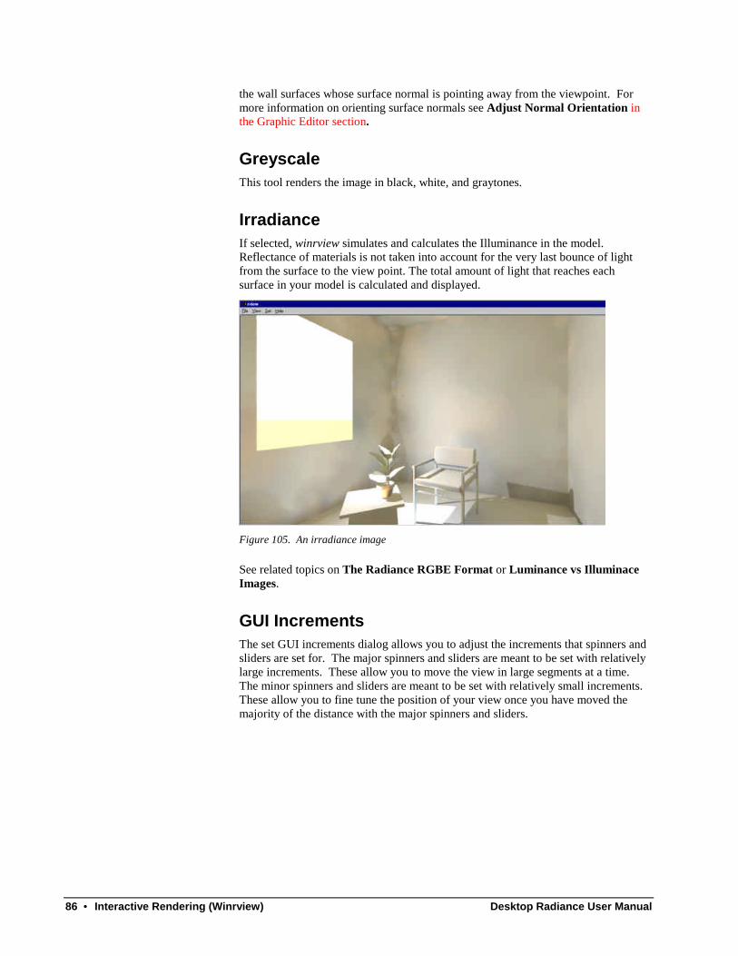
86 • Interactive Rendering (Winrview) Desktop Radiance User Manual
the wall surfaces whose surface normal is pointing away from the viewpoint. Formore information on orienting surface normals see Adjust Normal Orientation inthe Graphic Editor section.
GreyscaleThis tool renders the image in black, white, and graytones.
IrradianceIf selected, winrview simulates and calculates the Illuminance in the model.Reflectance of materials is not taken into account for the very last bounce of lightfrom the surface to the view point. The total amount of light that reaches eachsurface in your model is calculated and displayed.
Figure 105. An irradiance image
See related topics on The Radiance RGBE Format or Luminance vs IlluminaceImages.
GUI IncrementsThe set GUI increments dialog allows you to adjust the increments that spinners andsliders are set for. The major spinners and sliders are meant to be set with relativelylarge increments. These allow you to move the view in large segments at a time.The minor spinners and sliders are meant to be set with relatively small increments.These allow you to fine tune the position of your view once you have moved themajority of the distance with the major spinners and sliders.

Desktop Radiance User Manual Interactive Rendering (Winrview) • 87
Figure 106. The Set GUI increments dialog box
Exposure
When using the exposure tool, the higher the setting, the brighter the image willbe. When “Relative Mode” is selected, the exposure will be set relative to yourchoice of either a point that you select in the image or relative to the average value inthe image.
Figure 107. The winrview Exposure tool
Frame
This tool allows you to frame a section of an image for refinement. Afterclicking on “F” you are prompted to select an area for refinement. Use the cursor todrag a box around an area of the image. To select the entire image, draw a boxaround the entire winrview window. There is no frame all command as in previousUnix versions of rview.
Redraws a New image
This tool redraws/regenerates a new image. This is sometimes necessary if theimage has been corrupted by other dialog boxes, or if you have significantly changedyour calculation parameters and want to start over.

88 • Interactive Rendering (Winrview) Desktop Radiance User Manual
Winrview Parameters Dialog box
The winrview parameters define the level of accuracy for the simulated image.The settings in this dialog box will determine if your model will simulate an imagequickly or more slowly to a high level of accuracy. NOTE: if you want a highlyaccurate image, use batch mode instead of interactive. In the winrviewparameters dialog box you can manipulate things such as the number of ambientbounces that should take place. For information on choosing recommended valuesfor winrview parameter settings see the Desktop Radiance User Manual→ Tips andTechniques→ Setting Rendering Options. This table will give you minimum,maximum, fast, and accurate values. In addition it tells you particular settings thatcan greatly affect the rendering time of your model.
Ambient Parameter Tab
The Set Parameters→ Ambient dialog box (Figure 108) below sets the parametersfor the ambient light in the scene. To access the Ambient Parameters dialog box goto rview→ Set→ Parameters and click on the AMBIENT tab.
Figure 108. The Ambient Tab in the Parameter Dialog Box
Value: three boxes representing red (top), green (middle), and blue (bottom).Increasing these values evenly can make the scene darker, decreasing them willmake it lighter.
Weight: the average weight of the indirect light. As new indirect lights arecomputed the average value will be modified. For a scene that includes indoor andoutdoor spaces, a value of zero is appropriate and is the default.
Accuracy: the percent error allowd in lighting calculations. The smaller the number,the smoother the rendering. A value of 0.3 is a reasonable level to begin with. Therange of possible values that can be entered is between 0 and 0.5. Lower numbersare more accurate.
Divisions: the number of divisions of the hemisphere in the ambient lighting montecarlo calculation. A value of zero implies no indirect calculation. A reasonablevalue to begin with is 128. The range of possible values that can be entered isbetween 0 and 4096. Higher numbers are more accurate.
Super-samples: specifies the maximum number of additional rays to be traced perambient division. Where there is a big difference in value from adjacent rays. Areasonable value to begin with is half of the ambient divisions. The range of
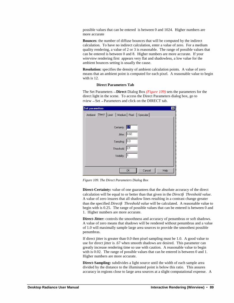
Desktop Radiance User Manual Interactive Rendering (Winrview) • 89
possible values that can be entered is between 0 and 1024. Higher numbers aremore accurate
Bounces: the number of diffuse bounces that will be computed by the indirectcalculation. To have no indirect calculation, enter a value of zero. For a mediumquality rendering, a value of 2 or 3 is reasonable. The range of possible values thatcan be entered is between 0 and 8. Higher numbers are more accurate. If yourwinrview rendering first appears very flat and shadowless, a low value for theambient bounces setting is usually the cause.
Resolution: specifies the density of ambient calculation points. A value of zeromeans that an ambient point is computed for each pixel. A reasonable value to beginwith is 12.
Direct Parameters Tab
The Set Parameters→ Direct Dialog Box (Figure 109) sets the parameters for thedirect light in the scene. To access the Direct Parameters dialog box, go torview→ Set→ Parameters and click on the DIRECT tab.
Figure 109. The Direct Parameters Dialog Box
Direct-Certainty: value of one guarantees that the absolute accuracy of the directcalculation will be equal to or better than that given in the Direct→ Threshold value.A value of zero insures that all shadow lines resulting in a contrast change greaterthan the specified Direct→ Threshold value will be calculated. A reasonable value tobegin with is 0.25. The range of possible values that can be entered is between 0 and1. Higher numbers are more accurate.
Direct-Jitter: controls the smoothness and accuracy of penumbras or soft shadows.A value of zero means that shadows will be rendered without penumbras and a valueof 1.0 will maximally sample large area sources to provide the smoothest possiblepenumbras.
If direct jitter is greater than 0.0 then pixel sampling must be 1.0. A good value touse for direct jitter is .67 when smooth shadows are desired. This parameter cangreatly increase rendering time so use with caution. A reasonable value to beginwith is 0.02. The range of possible values that can be entered is between 0 and 1.Higher numbers are more accurate.
Direct-Sampling: subdivides a light source until the width of each sample areadivided by the distance to the illuminated point is below this ratio. This assuresaccuracy in regions close to large area sources at a slight computational expense. A

90 • Interactive Rendering (Winrview) Desktop Radiance User Manual
value of zero turns source subdivision off, sending at most one shadow ray to eachlight source. Large area sources are subdivided into at most 64 patches which canlead to “hot spots” on immediately adjacent surfaces.
Direct-Threshold: minimum light value that a light source must have to be testedfor shadows. A value of zero means all light sources will be tested for shadows. Areasonable value to begin with is 0.2. The range of possible values that can beentered is between 0 and 1. Lower numbers are more accurate.
Direct-Visibility: allows you to make light sources appear black when looked atdirectly, but light output will still be taken into account for the simulation andanalysis. A value of zero will turn off the light source visibility. Any numbergreater than zero will turn it on.
Limit Parameters Tab
To access the Limit Parameters dialog box (Figure 110), go torview→ Set→ Parameters and click on the LIMIT tab.
Figure 110. The Limit Parameters Dialog Box
Limit-Reflection: defines the maximum number of specularly reflected andrefracted rays that can be spawned for each initial view ray. A reasonable value tobegin with is 6. The possible range of values that can be entered is between 0 and16. Higher numbers are more accurate.
Limit-Weight: the weight function stops the generation of specular rays when thepotential contribution is less than the specified minimum value. If the amountmeasured is less then the specified minimum weight, additional rays will not betraced. A reasonable value to begin with is 0.02. The possible range of values thatcan be entered is between 0 and 0.05. Lower numbers are more accurate.
Medium Parameters Tab
Parameters in the Medium tab affect the way light is traced through “participatingmedia” such as mist or fog. Volumes of participating media must be modeled withthe appropriate Radiance material. Such materials are not yet available in DesktopRadiance.
To access the participating Medium Parameters dialog box (Figure 111), go torview→ Set→ Parameters and click on the MEDIUM tab.

Desktop Radiance User Manual Interactive Rendering (Winrview) • 91
Figure 111. The participating Medium Parameters Dialog Box controls parameters related tothe rendering of fog and mist.
Scattering Albedo: determines whether light from a medium is absorbed orscattered. From top to bottom the boxes stand for Red light, Green light, Blue light.Only values between 0 and 1 can be entered. A zero will cause all light nottransmitted by a medium to be absorbed. A one will result in all light not transmittedto be scattered elsewhere.
Extinction Coefficient: refers to the distance that light will be scattered or absorbed.The three boxes from top to bottom stand for red light, green light, blue light.
Scattering Eccentricity: defines how much light scattering will tend towards theforward direction. Only values between 0 and 1 can be entered. A value of one willresult in the most forward tending light scattering.
Mist Sampling Distance: defines the distance between samples taken during asource scattering. A value of zero means that only one sample will be taken.
Pixel Parameters Tab
To access the Pixel Parameters dialog box (Figure 112), go torview→ Set→ Parameters and click on the PIXEL tab.
Figure 112. The Pixel Parameters Dialog Box
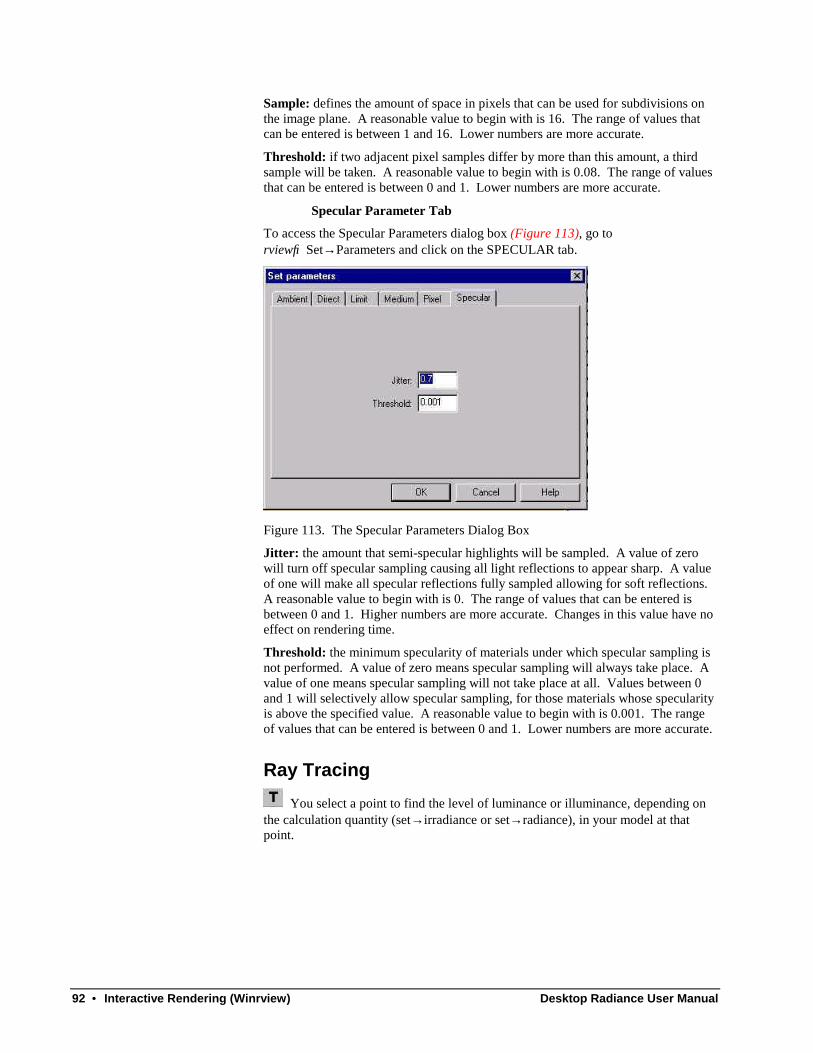
92 • Interactive Rendering (Winrview) Desktop Radiance User Manual
Sample: defines the amount of space in pixels that can be used for subdivisions onthe image plane. A reasonable value to begin with is 16. The range of values thatcan be entered is between 1 and 16. Lower numbers are more accurate.
Threshold: if two adjacent pixel samples differ by more than this amount, a thirdsample will be taken. A reasonable value to begin with is 0.08. The range of valuesthat can be entered is between 0 and 1. Lower numbers are more accurate.
Specular Parameter Tab
To access the Specular Parameters dialog box (Figure 113), go torview→ Set→ Parameters and click on the SPECULAR tab.
Figure 113. The Specular Parameters Dialog Box
Jitter: the amount that semi-specular highlights will be sampled. A value of zerowill turn off specular sampling causing all light reflections to appear sharp. A valueof one will make all specular reflections fully sampled allowing for soft reflections.A reasonable value to begin with is 0. The range of values that can be entered isbetween 0 and 1. Higher numbers are more accurate. Changes in this value have noeffect on rendering time.
Threshold: the minimum specularity of materials under which specular sampling isnot performed. A value of zero means specular sampling will always take place. Avalue of one means specular sampling will not take place at all. Values between 0and 1 will selectively allow specular sampling, for those materials whose specularityis above the specified value. A reasonable value to begin with is 0.001. The rangeof values that can be entered is between 0 and 1. Lower numbers are more accurate.
Ray Tracing
You select a point to find the level of luminance or illuminance, depending onthe calculation quantity (set→ irradiance or set→ radiance), in your model at thatpoint.

Desktop Radiance User Manual Interactive Rendering (Winrview) • 93
Figure 114. The Raytrace information dialog box
The first line of output provides the name of the material (e.g. 2k217)associated with the surface that the traced ray struck in the modelfollowed by the surface type (e.g. polygon) followed by the surfaceidentifier (e.g. document_53.2.0).
The second line of output provides the location in space that the raystruck (x, y, z coordinates)(e.g. -2.32832 e-010, 79.303, 86.9679) followed by thelength of the ray from thecamera position to that point (e.g. 117.71) in the units of your model.
The third line of output provides the computed luminance or illuminancevalue, first in red, green and blue spectral quantities, then in averageluminance or illuminance quantity.
If your calculation quantity is set to illuminance, this value willreport the illuminance in Lux. If your calculation quantity is set toluminance, this value will report the luminance in nits or candelas persquare meter. These units are always displayed in SI units, regardlessof the units specified in the preferences dialog box.
The output from tracing rays as well as any error messages generated during the ray-tracing process will be saved to a log file. See Save Log File As or View Log File.
Set View
The Set View Dialog Box (Figure 115) sets specifications for the view orcamera. The settings to specify include: Type, Size, Viewpoint, Clipping Plane,Direction, Up, and Offset.
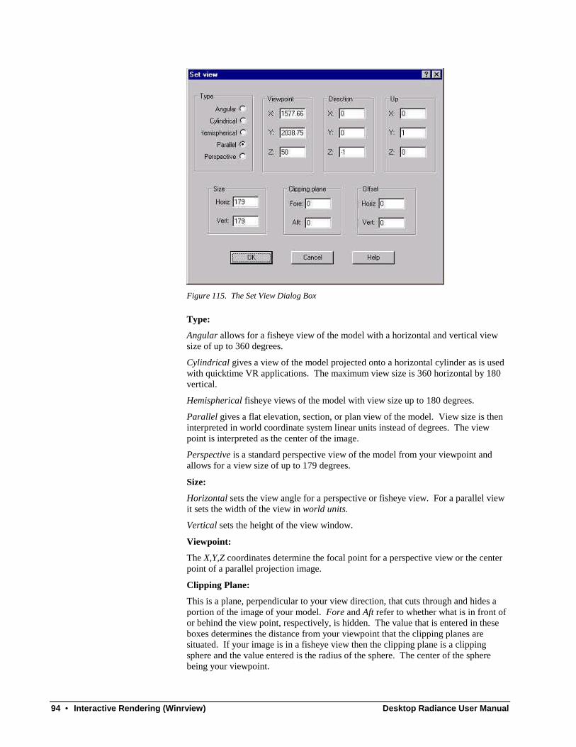
94 • Interactive Rendering (Winrview) Desktop Radiance User Manual
Figure 115. The Set View Dialog Box
Type:
Angular allows for a fisheye view of the model with a horizontal and vertical viewsize of up to 360 degrees.
Cylindrical gives a view of the model projected onto a horizontal cylinder as is usedwith quicktime VR applications. The maximum view size is 360 horizontal by 180vertical.
Hemispherical fisheye views of the model with view size up to 180 degrees.
Parallel gives a flat elevation, section, or plan view of the model. View size is theninterpreted in world coordinate system linear units instead of degrees. The viewpoint is interpreted as the center of the image.
Perspective is a standard perspective view of the model from your viewpoint andallows for a view size of up to 179 degrees.
Size:
Horizontal sets the view angle for a perspective or fisheye view. For a parallel viewit sets the width of the view in world units.
Vertical sets the height of the view window.
Viewpoint:
The X,Y,Z coordinates determine the focal point for a perspective view or the centerpoint of a parallel projection image.
Clipping Plane:
This is a plane, perpendicular to your view direction, that cuts through and hides aportion of the image of your model. Fore and Aft refer to whether what is in front ofor behind the view point, respectively, is hidden. The value that is entered in theseboxes determines the distance from your viewpoint that the clipping planes aresituated. If your image is in a fisheye view then the clipping plane is a clippingsphere and the value entered is the radius of the sphere. The center of the spherebeing your viewpoint.
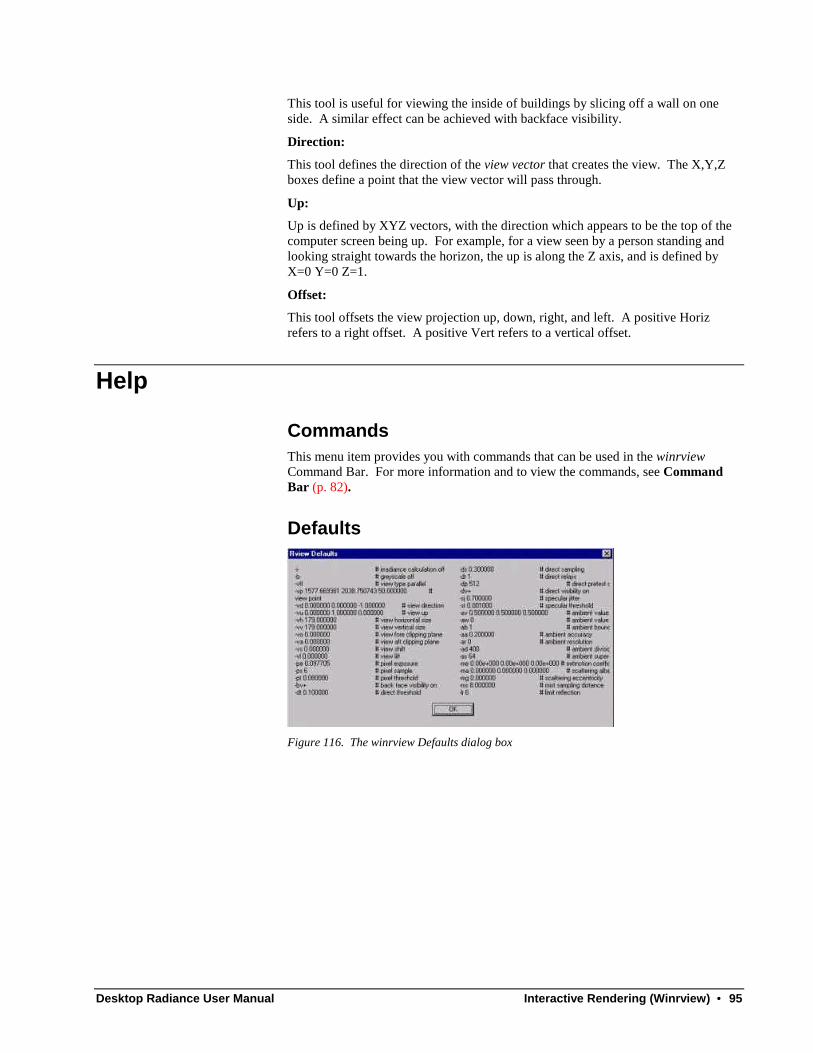
Desktop Radiance User Manual Interactive Rendering (Winrview) • 95
This tool is useful for viewing the inside of buildings by slicing off a wall on oneside. A similar effect can be achieved with backface visibility.
Direction:
This tool defines the direction of the view vector that creates the view. The X,Y,Zboxes define a point that the view vector will pass through.
Up:
Up is defined by XYZ vectors, with the direction which appears to be the top of thecomputer screen being up. For example, for a view seen by a person standing andlooking straight towards the horizon, the up is along the Z axis, and is defined byX=0 Y=0 Z=1.
Offset:
This tool offsets the view projection up, down, right, and left. A positive Horizrefers to a right offset. A positive Vert refers to a vertical offset.
Help
CommandsThis menu item provides you with commands that can be used in the winrviewCommand Bar. For more information and to view the commands, see CommandBar (p. 82).
Defaults
Figure 116. The winrview Defaults dialog box