designing a meta-model for a generic robotic agent …niadr/publications/liacc...designing a...
TRANSCRIPT
Information Sciences 195 (2012) 190–210
Contents lists available at SciVerse ScienceDirect
Information Sciences
journal homepage: www.elsevier .com/locate / ins
Designing a meta-model for a generic robotic agent systemusing Gaia methodology
Daniel Castro Silva a,⇑, Rodrigo A.M. Braga b, Luís Paulo Reis b, Eugénio Oliveira b
a University of Coimbra, Department of Informatics Engineering / CISUC - Center for Informatics and Systems of the University of Coimbra, Pólo II, Pinhal deMarrocos 3030-290 Coimbra, Portugalb FEUP – Faculty of Engineering of the University of Porto, Department of Informatics Engineering/LIACC – Artificial Intelligence and Computer Science Laboratory,Rua Dr. Roberto Frias s/n, 4200-465 Porto, Portugal
a r t i c l e i n f o
Article history:Received 6 January 2010Received in revised form 15 April 2011Accepted 7 January 2012Available online 24 January 2012
Keywords:Multi-robot systemsOpen systems meta-modelAgent-oriented software engineeringGaia
0020-0255/$ - see front matter � 2012 Elsevier Incdoi:10.1016/j.ins.2012.01.029
⇑ Corresponding author. Tel.: +351 91 670 69 14.E-mail addresses: [email protected] (D.C. Silva), rodr
1 More information available online at http://ww2 More information available online at http://ww
a b s t r a c t
The emergence of multi-agent systems in the past years has led to the development of newmethodologies to assist in the requirements and architectural analysis, as well as in thedesign phases of such systems. Consequently, several Agent Oriented Software Engineering(AOSE) methodologies have been proposed. In this paper, we analyze some AOSE method-ologies, including Gaia, which supports the architectural design stage, and some proposedextensions. We then use an adapted version of this methodology to design an abstract gen-eric system meta-model for a multi-robot application, which can be used as a basis for thedesign of these systems, avoiding or shortening repetitive tasks common to most systems.Based on the proposed Generic Robotic Agent Meta-Model (GRAMM), two distinct modelsfor two different applications are derived, demonstrating the versatility and adaptability ofthe meta-model. By adapting the Gaia methodology to the design of open systems, thiswork makes the designers’ job faster and easier, decreasing the time needed to completeseveral tasks, while at the same time maintaining a high-level overview of the system.
� 2012 Elsevier Inc. All rights reserved.
1. Introduction
In the past years, systems that support the use of mobile robots have emerged at a growing rate. These systems are usedin a wide range of areas, including military [19], medical [9], industrial [49], household applications [31,30], and othersmaller or more specific fields of research, such as the Robocup Rescue1 and Soccer competitions,2 as well as several projectscurrently under development. Despite the need to develop coordination methodologies among the several entities, the benefitsof a system capable of working in a distributed manner (with simpler entities performing smaller tasks that together contributeto a larger task completion) are certainly greater than the complexities introduced by this model [1].
Several Agent-Oriented Software Engineering (AOSE) methodologies have been proposed over the years to help modelmulti-agent systems, some deriving from existing more traditional software engineering methodologies (usually object-oriented approaches), others with a more innovative origin. These methodologies are diverse in terms of the developmentphases they support, from requirement elicitation to implementation.
The main goal of the work presented in this paper is to introduce a meta-model for a generic robotic agent system, thatcan be used as a basis for the modeling of such systems, thus avoiding or shortening repetitive tasks common to most ofthese systems. This meta-model can be achieved by using a methodology that supports the architectural design stage.
. All rights reserved.
[email protected] (R.A.M. Braga), [email protected] (L.P. Reis), [email protected] (E. Oliveira).w.robocuprescue.org/.w.robocup.org/.
D.C. Silva et al. / Information Sciences 195 (2012) 190–210 191
One such methodology is Gaia, a somewhat generic methodology that excludes requirements elicitation and implementa-tion, focusing on analysis and design of the system [47]. Even though the Gaia methodology was originally intended to beused in the design of organizational systems, with a more defined set of hierarchical organization, it can also be used inthe design of open systems, with minor modifications, as introduced in Section 4.
In the following section, we present a brief overview on some existing AOSE methodologies, as well as a brief analysis onsome proposed extensions to the Gaia methodology (Section 2.4). In more detail, we present and analyze:
� the differences between the original Gaia methodology and the official proposed improvements� the proposed AUML extensions� the proposed ROADMAP extension� the extensions and replacements as proposed by [10]
We also introduce a model for an extended version of the Gaia methodology, using the Software Process EngineeringMetamodel (SPEM) 2.0 notation – see Section 3. This is believed to be an original contribution that provides a higher formal-ization and facilitates a better understanding of the Gaia methodology.
In Section 4, we introduce the proposed meta-model for a multi-agent system including several robotic vehicles and someperipheral agents using Gaia-based methodology. We then instantiate the Generic Robotic Agent Meta-Model (GRAMM) intotwo distinct designs for two different systems (Section 5).
Finally, on Section 6, we present some conclusions about the work that has already been done, as well as the guiding linesfor the next steps to be taken.
2. AOSE methodologies and extensions
The ever-growing use of agent-based technology and applications has brought forward the need for methodologies thatcould aid designers not only in development and deployment, but also in the early analysis and design phases of a project, ina manner similar to what traditional software engineering techniques have done for more conventional software projects,namely when using an object-oriented paradigm [27].
In this section, we briefly introduce some of the most widely known AOSE methodologies that have emerged in the pastyears (for a more complete and detailed review of existing methodologies, see [4] or chapter 7 of [41]).
2.1. MaSE
The Multiagent Systems Engineering (MaSE) methodology was introduced in 2000 as a comprehensive methodology,including analysis and design stages [46]. It uses a number of graphical models to describe goals, behaviors, agent types,and agent communication interfaces, also providing detailed definition of internal agent design [16]. In the first analysisphase, goals are determined and structured by analyzing an already existing initial system specification. The second analysisphase is centered around use cases, detecting roles, use cases and use case scenarios from the system specification. In thethird analysis phase, the identified roles are refined, producing a more detailed description of each role and their respectivegoals, as well as interactions with other roles. In the design stage, roles are mapped into specific agent classes; communica-tion protocols between agent classes are detailed; the internal details of each agent class are defined, using components andconnectors; and finally a system-wide deployment diagram is created. A tool named agentTool was developed to support theMaSE methodology (and more recently the Organization-based MaSE, or O-MaSE), from the initial system specification toimplementation, using a set of inter-related graphical models [15].
2.2. Tropos
Tropos was introduced in 2002 as a comprehensive AOSE methodology, encompassing all stages of project design, fromearly requirements elicitation to detailed design [24]. Tropos can be considered as loosely based on a use-case model used intraditional Software Engineering methodologies. Its key concepts include actor, goal, plan, resource, dependency, capabilityand belief [8]. During the early requirements elicitation, actors and goals are identified from stakeholders and their objec-tives, using a goal-oriented analysis. Dependencies between actors and goals are also identified. In the late requirementsstage, all functional and non-functional requirements for the system are specified in more detail. In this stage, the systemis considered as a single actor, while external entities present in the environment are considered as interacting actors.The architectural design stage produces a model of the system architecture, describing how components work together. Dur-ing the detailed design stage, detailed models of each component are produced, showing how goals are fulfilled by agents. Inthis stage, details such as agent communication language and protocols are specified using a more detailed modeling lan-guage such as UML (Unified Modeling Language) [23].
2.3. Prometheus
Prometheus was introduced in 2002 as a result of industry and academy experience [38]. It provides support and a de-tailed process for specification to implementation stages of a project, and includes concepts such as goals, beliefs, plans and

192 D.C. Silva et al. / Information Sciences 195 (2012) 190–210
events. The methodology includes three phases: the system specification phase, which focuses on the system as a whole,identifying goals, functionalities and use case scenarios with the environment; the architectural design phase, which usesthe models produced in the previous stage to determine the agents that will be present in the system, how they will interactwith each other and react to events in the environment; and the detailed design phase, which produces detailed diagrams ofeach agent’s functionalities and capabilities, as well as several other implementation details [45]. A tool named PDT(Prometheus Design Tool) was developed to provide support to the Prometheus methodology in the design of agent systems[37]. Many Prometheus concepts also map directly into the JACK system,3 which can be used to generate agent skeleton code[39].
2.4. Gaia
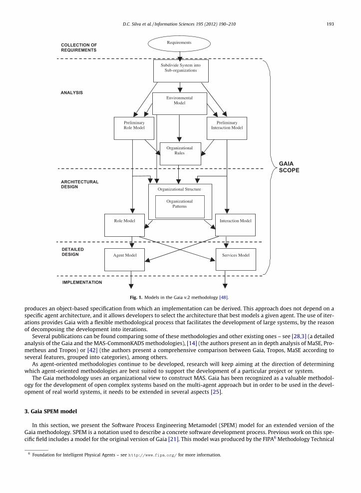
The original Gaia methodology was proposed in 2000, by Wooldridge, Jennings and Kinny, entailing both analysis anddesign phases, but not requirements elicitation or implementation [47]. In the analysis stage, a roles model (containingthe key roles in the system, their permissions and responsibilities, along with the protocols and activities in which they par-ticipate) and an interaction model (containing the patterns of inter-role interaction) are produced. In the design stage, anagent model (aggregating roles into agent types), a services model (derived from the activities and protocols of each role)and an acquaintance model (defining communication links between agent types) are produced. In the next paragraphs,we will analyze some proposed extensions to the Gaia methodology (a more detailed analysis of some of these extensionscan be found in [12]).
2.4.1. ROADMAP extensionThe ROADMAP (Role Oriented Analysis and Design for Multi-Agent Programming) extensions to Gaia were proposed in
2002, by Juan, Pearce and Sterling [29] and later further extended.4 ROADMAP introduces new features to the Gaia method-ology, in order to eliminate or mitigate some identified weaknesses: support for requirements gathering (by introducing a use-case model); new models to describe the domain knowledge and the environment (knowledge and environment models,respectively); levels of abstraction that allow iterative decomposition of the system; models and representations of social as-pects and individual characteristics; and runtime reflection modeling, to allow changes of social and individual aspects in run-time – by allowing roles to have read, write and change permissions on roles, role attributes (such as protocols) or a member ofan attribute (a specific protocol, for instance).
2.4.2. Gaia v.2The official extensions to Gaia (referred to as Gaia v.2 as to avoid ambiguity) were introduced in 2003, by Zambonelli,
Jennings and Wooldridge, enriching the original methodology [48]. The analysis stage was expanded to include an organi-zational model (decomposing the system into sub-organizations), an environment model (describing the environment inwhich the Multi-Agent System (MAS) will be situated) and the organizational rules (containing global organizational rulesthe system must respect and enforce). The design stage was divided into architectural design and detailed design stages. Inthe first, the roles and interaction diagrams are completed, and an organizational structure model is introduced (containingthe structure, topology and control regime of the system). In the second, the agent and service models are created (as in theoriginal methodology). Fig. 1 shows these models and their relations in the Gaia v.2 methodology in more detail.
2.4.3. AUML extensionsAgent UML (AUML5) was introduced in the year 2000 as a set of UML idioms and extensions for dealing with agents [36,2]. In
2004, Cernuzzi and Zambonelli propose that the Agent Interaction Protocol (AIP) (the core part of AUML) be used in conjunctionwith Gaia, as to provide a richer, more compact and formal notation for agent interaction, reducing ambiguity and allowing thespecification of multiple lifelines for the agent to choose from [13]. Although this had already been suggested earlier – for in-stance, in [29] (page 6) or [48](page 348) –, it had never been detailed.
2.4.4. Other extensionsIn [10], Castro and Oliveira used the Gaia methodology for modeling an airline company operations control center, and
propose some complements (and replacements) to some of its models. They propose the replacement of protocol tables withUML 2.0 interaction diagrams; the formal notation of the organizational structure with UML 2.0 diagram; the agent modelwith a UML 2.0 class diagram; and the service model with a UML 2.0 class diagram. They also suggest to jointly use a UML 2.0representation of roles and interaction diagram to help to better visualize roles, activities and protocols; and a few combinedgraphical representations to complement the preliminary role and interaction models and the organizational structure.
In [25], Gonzalez-Palacios and Luck extended the Gaia methodology by introducing an agent design phase, and enhancingthe methodological process with the use of iterations. The agent design phase follows the detailed design phase of Gaia and
3 More information about the JACK system and more recent developments available online at http://www.agent-software.com.au/products/jack/index.html.
4 More publications about the ROADMAP methodology are available online from http://www.agentlab.unimelb.edu.au/publications/Keyword/
ROADMAP. html.5 More information available online at http://www.auml.org/.
Preliminary Role Model
Preliminary Interaction Model
Environmental Model
Requirements
OrganizationalRules
OrganizationalPatterns
Organizational Structure
Interaction Model Role Model
Services Model Agent Model
IMPLEMENTATION
ARCHITECTURALDESIGN
ANALYSIS
COLLECTION OF REQUIREMENTS
GAIASCOPE
Subdivide System into Sub-organizations
DETAILEDDESIGN
Fig. 1. Models in the Gaia v.2 methodology [48].
D.C. Silva et al. / Information Sciences 195 (2012) 190–210 193
produces an object-based specification from which an implementation can be derived. This approach does not depend on aspecific agent architecture, and it allows developers to select the architecture that best models a given agent. The use of iter-ations provides Gaia with a flexible methodological process that facilitates the development of large systems, by the reasonof decomposing the development into iterations.
Several publications can be found comparing some of these methodologies and other existing ones – see [28,3] (a detailedanalysis of the Gaia and the MAS-CommonKADS methodologies), [14] (the authors present an in depth analysis of MaSE, Pro-metheus and Tropos) or [42] (the authors present a comprehensive comparison between Gaia, Tropos, MaSE according toseveral features, grouped into categories), among others.
As agent-oriented methodologies continue to be developed, research will keep aiming at the direction of determiningwhich agent-oriented methodologies are best suited to support the development of a particular project or system.
The Gaia methodology uses an organizational view to construct MAS. Gaia has been recognized as a valuable methodol-ogy for the development of open complex systems based on the multi-agent approach but in order to be used in the devel-opment of real world systems, it needs to be extended in several aspects [25].
3. Gaia SPEM model
In this section, we present the Software Process Engineering Metamodel (SPEM) model for an extended version of theGaia methodology. SPEM is a notation used to describe a concrete software development process. Previous work on this spe-cific field includes a model for the original version of Gaia [21]. This model was produced by the FIPA6 Methodology Technical
6 Foundation for Intelligent Physical Agents – see http://www.fipa.org/ for more information.
Work Product
UML / Formal Model
Role
Task
Activity
Phase
Process Package
(a) SPEM Notation
GAIA
<<Discipline>>Requirements
Capture
<<Discipline>>Analysis
<<Discipline>>Architectural
Design
<<Discipline>>Detailed Design
(b) Stages of the Gaia Methodology
Fig. 2. SPEM notation and stages of the gaia methodology.
194 D.C. Silva et al. / Information Sciences 195 (2012) 190–210
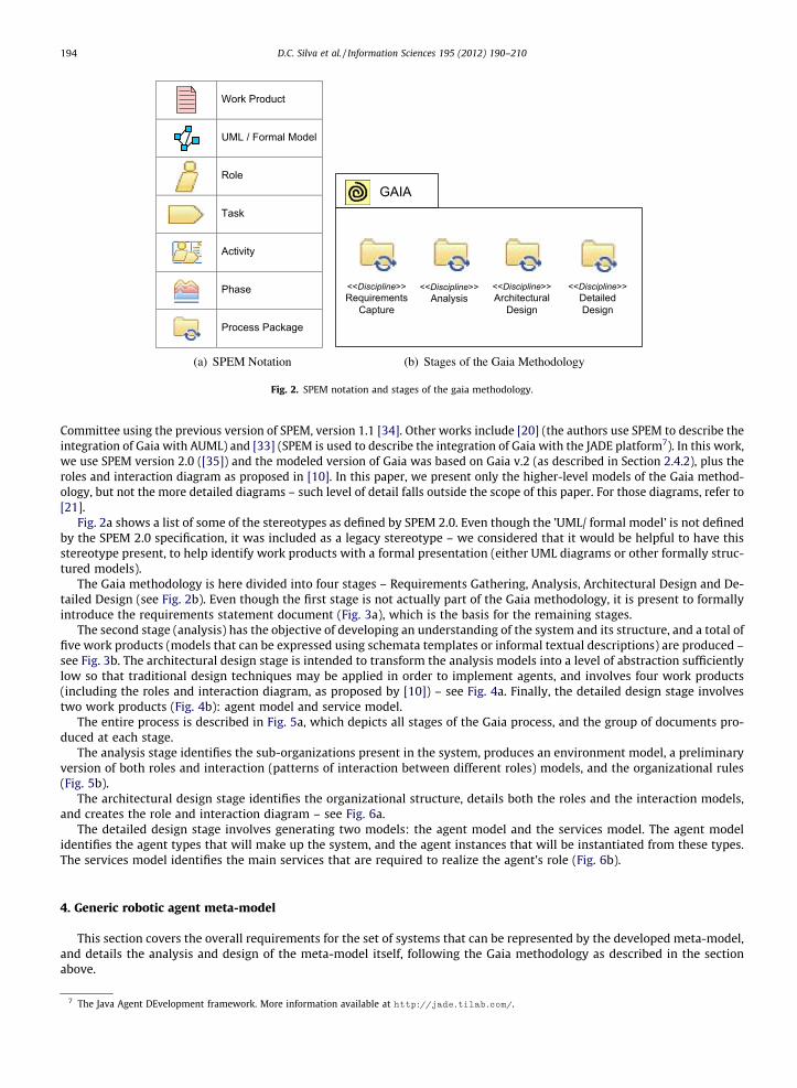
Committee using the previous version of SPEM, version 1.1 [34]. Other works include [20] (the authors use SPEM to describe theintegration of Gaia with AUML) and [33] (SPEM is used to describe the integration of Gaia with the JADE platform7). In this work,we use SPEM version 2.0 ([35]) and the modeled version of Gaia was based on Gaia v.2 (as described in Section 2.4.2), plus theroles and interaction diagram as proposed in [10]. In this paper, we present only the higher-level models of the Gaia method-ology, but not the more detailed diagrams – such level of detail falls outside the scope of this paper. For those diagrams, refer to[21].
Fig. 2a shows a list of some of the stereotypes as defined by SPEM 2.0. Even though the ’UML/ formal model’ is not definedby the SPEM 2.0 specification, it was included as a legacy stereotype – we considered that it would be helpful to have thisstereotype present, to help identify work products with a formal presentation (either UML diagrams or other formally struc-tured models).
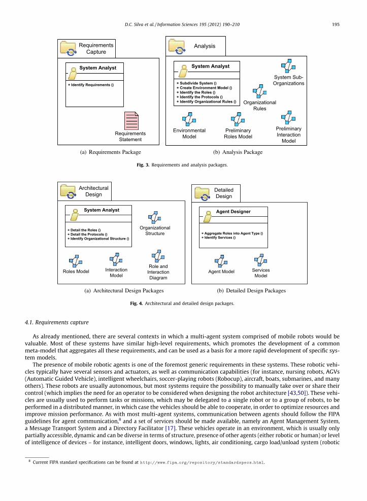
The Gaia methodology is here divided into four stages – Requirements Gathering, Analysis, Architectural Design and De-tailed Design (see Fig. 2b). Even though the first stage is not actually part of the Gaia methodology, it is present to formallyintroduce the requirements statement document (Fig. 3a), which is the basis for the remaining stages.
The second stage (analysis) has the objective of developing an understanding of the system and its structure, and a total offive work products (models that can be expressed using schemata templates or informal textual descriptions) are produced –see Fig. 3b. The architectural design stage is intended to transform the analysis models into a level of abstraction sufficientlylow so that traditional design techniques may be applied in order to implement agents, and involves four work products(including the roles and interaction diagram, as proposed by [10]) – see Fig. 4a. Finally, the detailed design stage involvestwo work products (Fig. 4b): agent model and service model.
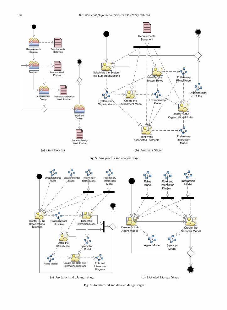
The entire process is described in Fig. 5a, which depicts all stages of the Gaia process, and the group of documents pro-duced at each stage.
The analysis stage identifies the sub-organizations present in the system, produces an environment model, a preliminaryversion of both roles and interaction (patterns of interaction between different roles) models, and the organizational rules(Fig. 5b).
The architectural design stage identifies the organizational structure, details both the roles and the interaction models,and creates the role and interaction diagram – see Fig. 6a.
The detailed design stage involves generating two models: the agent model and the services model. The agent modelidentifies the agent types that will make up the system, and the agent instances that will be instantiated from these types.The services model identifies the main services that are required to realize the agent’s role (Fig. 6b).
4. Generic robotic agent meta-model
This section covers the overall requirements for the set of systems that can be represented by the developed meta-model,and details the analysis and design of the meta-model itself, following the Gaia methodology as described in the sectionabove.
7 The Java Agent DEvelopment framework. More information available at http://jade.tilab.com/.
Requirements Capture
System Analyst
+ Identify Requirements ()
Requirements Statement
(a) Requirements Package
Analysis
System Analyst
+ Subdivide System ()+ Create Environment Model ()+ Identify the Roles ()+ Identify the Protocols ()+ Identify Organizational Rules ()
Environmental Model
Organizational Rules
Preliminary Roles Model
Preliminary Interaction
Model
System Sub-Organizations
(b) Analysis Package
Fig. 3. Requirements and analysis packages.
Architectural Design
System Analyst
+ Detail the Roles ()+ Detail the Protocols ()+ Identify Organizational Structure ()
Roles Model Interaction Model
Organizational Structure
Role and Interaction Diagram
(a) Architectural Design Packages
Detailed Design
Agent Designer
+ Aggregate Roles into Agent Type ()+ Identify Services ()
Agent Model Services Model
(b) Detailed Design Packages
Fig. 4. Architectural and detailed design packages.
D.C. Silva et al. / Information Sciences 195 (2012) 190–210 195
4.1. Requirements capture
As already mentioned, there are several contexts in which a multi-agent system comprised of mobile robots would bevaluable. Most of these systems have similar high-level requirements, which promotes the development of a commonmeta-model that aggregates all these requirements, and can be used as a basis for a more rapid development of specific sys-tem models.
The presence of mobile robotic agents is one of the foremost generic requirements in these systems. These robotic vehi-cles typically have several sensors and actuators, as well as communication capabilities (for instance, nursing robots, AGVs(Automatic Guided Vehicle), intelligent wheelchairs, soccer-playing robots (Robocup), aircraft, boats, submarines, and manyothers). These robots are usually autonomous, but most systems require the possibility to manually take over or share theircontrol (which implies the need for an operator to be considered when designing the robot architecture [43,50]). These vehi-cles are usually used to perform tasks or missions, which may be delegated to a single robot or to a group of robots, to beperformed in a distributed manner, in which case the vehicles should be able to cooperate, in order to optimize resources andimprove mission performance. As with most multi-agent systems, communication between agents should follow the FIPAguidelines for agent communication,8 and a set of services should be made available, namely an Agent Management System,a Message Transport System and a Directory Facilitator [17]. These vehicles operate in an environment, which is usually onlypartially accessible, dynamic and can be diverse in terms of structure, presence of other agents (either robotic or human) or levelof intelligence of devices – for instance, intelligent doors, windows, lights, air conditioning, cargo load/unload system (robotic
8 Current FIPA standard specifications can be found at http://www.fipa.org/repository/standardspecs.html.
Requirements Capture
Analysis
Architectural Design
Architectural Design Work Product
Analysis Work Product
Requirements Statement
Detailed DesignWork Product
Detailed Design
(a) Gaia Process
Requirements Statement
Environmental Model
Organizational Rules
Preliminary Roles Model
Preliminary Interaction
Model
System Sub-Organizations
Identify the System Roles
Subdivide the System into Sub-organizations
Identify the associated Protocols
Identify the Organizational Rules
Create the Environment Model
(b) Analysis Stage
Fig. 5. Gaia process and analysis stage.
Environmental Model
Organizational Rules
Preliminary Roles Model
Preliminary Interaction
Model
Roles Model
Interaction Model
Organizational Structure
Identify the Organizational
Structure
Role and Interaction Diagram
Create the Role and Interaction Diagram
Detail the Interaction Model
Detail the Roles Model
(a) Architectural Design Stage
Roles Model
Interaction Model
Agent Model Services Model
Role and Interaction Diagram
Create the Services Model
Create the Agent Model
(b) Detailed Design Stage
Fig. 6. Architectural and detailed design stages.
196 D.C. Silva et al. / Information Sciences 195 (2012) 190–210
D.C. Silva et al. / Information Sciences 195 (2012) 190–210 197
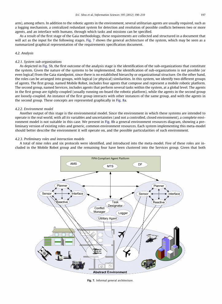
arm), among others. In addition to the robotic agents in the environment, several utilitarian agents are usually required, such asa logging mechanism, a centralized redundant system for detection and resolution of possible conflicts between two or moreagents, and an interface with humans, through which tasks and missions can be specified.
As a result of the first stage of the Gaia methodology, these requirements are collected and structured in a document thatwill act as the input for the following stages. Fig. 7 shows the general architecture of the system, which may be seen as asummarized graphical representation of the requirements specification document.
4.2. Analysis
4.2.1. System sub-organizationsAs depicted in Fig. 5b, the first outcome of the analysis stage is the identification of the sub-organizations that constitute
the system. Given the nature of the systems to be implemented, the identification of sub-organizations is not possible (oreven logical) from the Gaia standpoint, since there is no established hierarchy or organizational structure. On the other hand,the roles can be arranged into groups, with logical (or physical) similarities. In this system, we identify two different groupsof agents. The first group, named Mobile Robot, includes four agents that compose and represent a mobile robotic platform.The second group, named Services, includes agents that perform several tasks within the system, at a global level. The agentsin the first group are tightly-coupled (usually running on-board the robotic platform), while the agents in the second groupare loosely-coupled. An instance of the first group interacts with other instances of the same group, and with the agents inthe second group. These concepts are represented graphically in Fig. 8a.
4.2.2. Environment modelAnother output of this stage is the environmental model. Since the environment in which these systems are intended to
operate is the real world, with all its variables and uncertainties (and not a controlled, closed environment), a complete envi-ronment model is not suitable in this case. We present in Fig. 8b a general environment resources diagram, showing a pre-liminary version of existing roles and generic, common environment resources. Each system implementing this meta-modelshould better describe the environment it will operate on, and the possible particularities of such environment.
4.2.3. Preliminary roles and interaction modelsA total of nine roles and six protocols were identified, and introduced into the meta-model. Five of these roles are in-
cluded in the Mobile Robot group and the remaining four have been clustered into the Services group. Given that both
Fig. 7. Informal general architecture.
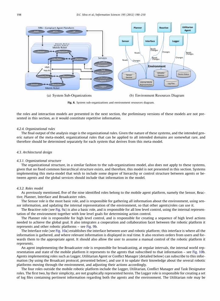
Fig. 8. System sub-organizations and environment resources diagram.
198 D.C. Silva et al. / Information Sciences 195 (2012) 190–210
the roles and interaction models are presented in the next section, the preliminary versions of these models are not pre-sented in this section, as it would constitute repetitive information.
4.2.4. Organizational rulesThe final output of the analysis stage is the organizational rules. Given the nature of these systems, and the intended gen-
eric nature of the meta-model, organizational rules that can be applied to all intended domains are somewhat rare, andtherefore should be determined separately for each system that derives from this meta-model.
4.3. Architectural design
4.3.1. Organizational structureThe organizational structure, in a similar fashion to the sub-organizations model, also does not apply to these systems,
given that no fixed common hierarchical structure exists, and therefore, this model is not presented in this section. Systemsimplementing this meta-model that wish to include some degree of hierarchy or control structure between agents or be-tween agents and the global services should include that information in the model.
4.3.2. Roles modelAs previously mentioned, five of the nine identified roles belong to the mobile agent platform, namely the Sensor, Reac-
tive, Planner, Interface and Broadcaster roles.The Sensor role is the most basic role, and is responsible for gathering all information about the environment, using sen-
sor information, and updating the internal representation of the environment, so that other agents/roles can use it.The Reactive role (see Fig. 9a) is also a basic role, and is responsible for all low level control, using the internal represen-
tation of the environment together with low level goals for determining action control.The Planner role is responsible for high level control, and is responsible for creating a sequence of high level actions
needed to achieve the global goal. It also integrates a cooperation and collaboration facet between the robotic platform itrepresents and other robotic platforms – see Fig. 9b.
The Interface role (see Fig. 10a) establishes the interface between user and robotic platform; this interface is where all theinformation is gathered, and where relevant information is displayed in real time. It also receives orders from users and for-wards them to the appropriate agent. It should also allow the user to assume a manual control of the robotic platform itrepresents.
An agent implementing the Broadcaster role is responsible for broadcasting, at regular intervals, the internal world rep-resentation and state of the mobile platform it represents to the agents that subscribed to that information – see Fig. 10b.Agents implementing roles such as Logger, Utilitarian Agent or Conflict Manager (detailed below) can subscribe to this infor-mation (by using the Broadcast protocol, presented below), and use it to update their knowledge about the several roboticplatforms moving through the environment, and adjusting their actions accordingly.
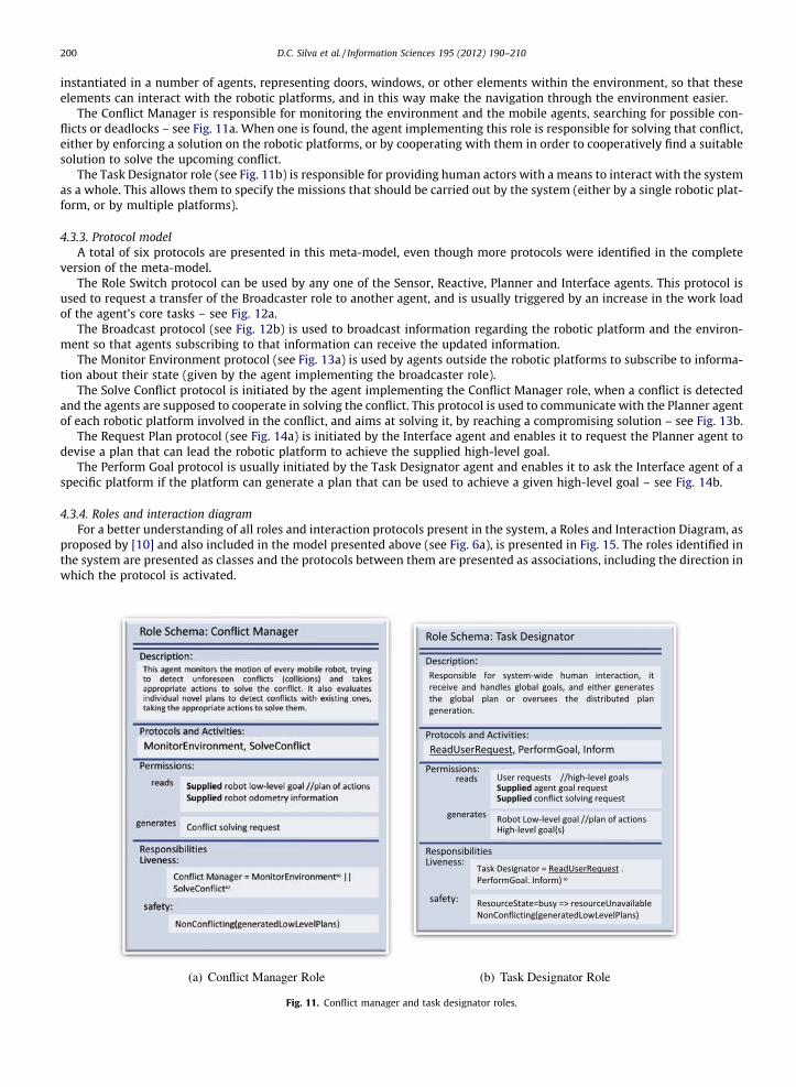
The four roles outside the mobile robotic platform include the Logger, Utilitarian, Conflict Manager and Task Designatorroles. The first two, by their simplicity, are not graphically represented herein. The Logger role is responsible for creating a setof log files containing pertinent information regarding both the agents and the environment. The Utilitarian role may be
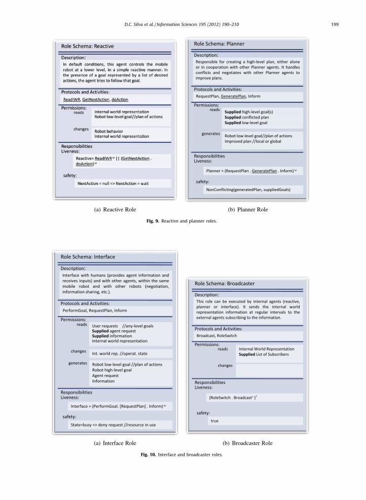
Fig. 9. Reactive and planner roles.
Fig. 10. Interface and broadcaster roles.
D.C. Silva et al. / Information Sciences 195 (2012) 190–210 199
200 D.C. Silva et al. / Information Sciences 195 (2012) 190–210
instantiated in a number of agents, representing doors, windows, or other elements within the environment, so that theseelements can interact with the robotic platforms, and in this way make the navigation through the environment easier.
The Conflict Manager is responsible for monitoring the environment and the mobile agents, searching for possible con-flicts or deadlocks – see Fig. 11a. When one is found, the agent implementing this role is responsible for solving that conflict,either by enforcing a solution on the robotic platforms, or by cooperating with them in order to cooperatively find a suitablesolution to solve the upcoming conflict.
The Task Designator role (see Fig. 11b) is responsible for providing human actors with a means to interact with the systemas a whole. This allows them to specify the missions that should be carried out by the system (either by a single robotic plat-form, or by multiple platforms).
4.3.3. Protocol modelA total of six protocols are presented in this meta-model, even though more protocols were identified in the complete
version of the meta-model.The Role Switch protocol can be used by any one of the Sensor, Reactive, Planner and Interface agents. This protocol is
used to request a transfer of the Broadcaster role to another agent, and is usually triggered by an increase in the work loadof the agent’s core tasks – see Fig. 12a.
The Broadcast protocol (see Fig. 12b) is used to broadcast information regarding the robotic platform and the environ-ment so that agents subscribing to that information can receive the updated information.
The Monitor Environment protocol (see Fig. 13a) is used by agents outside the robotic platforms to subscribe to informa-tion about their state (given by the agent implementing the broadcaster role).
The Solve Conflict protocol is initiated by the agent implementing the Conflict Manager role, when a conflict is detectedand the agents are supposed to cooperate in solving the conflict. This protocol is used to communicate with the Planner agentof each robotic platform involved in the conflict, and aims at solving it, by reaching a compromising solution – see Fig. 13b.
The Request Plan protocol (see Fig. 14a) is initiated by the Interface agent and enables it to request the Planner agent todevise a plan that can lead the robotic platform to achieve the supplied high-level goal.
The Perform Goal protocol is usually initiated by the Task Designator agent and enables it to ask the Interface agent of aspecific platform if the platform can generate a plan that can be used to achieve a given high-level goal – see Fig. 14b.
4.3.4. Roles and interaction diagramFor a better understanding of all roles and interaction protocols present in the system, a Roles and Interaction Diagram, as
proposed by [10] and also included in the model presented above (see Fig. 6a), is presented in Fig. 15. The roles identified inthe system are presented as classes and the protocols between them are presented as associations, including the direction inwhich the protocol is activated.
Fig. 11. Conflict manager and task designator roles.
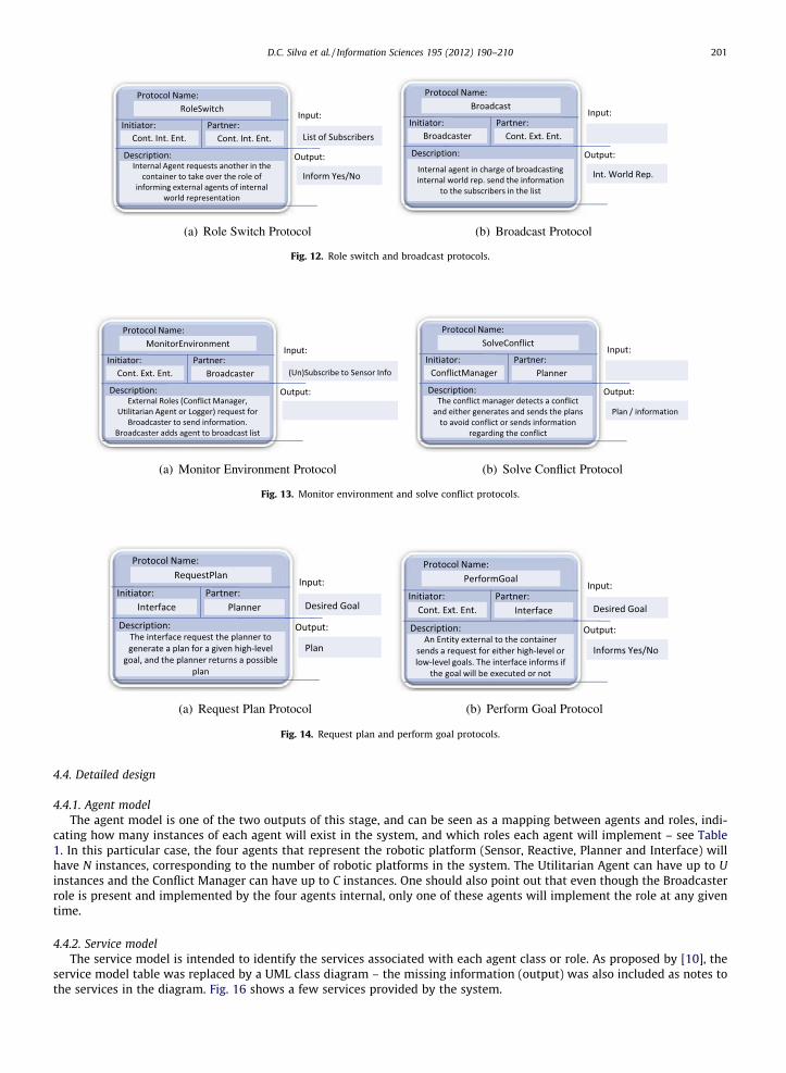
Fig. 12. Role switch and broadcast protocols.
Fig. 13. Monitor environment and solve conflict protocols.
Fig. 14. Request plan and perform goal protocols.
D.C. Silva et al. / Information Sciences 195 (2012) 190–210 201
4.4. Detailed design
4.4.1. Agent modelThe agent model is one of the two outputs of this stage, and can be seen as a mapping between agents and roles, indi-
cating how many instances of each agent will exist in the system, and which roles each agent will implement – see Table1. In this particular case, the four agents that represent the robotic platform (Sensor, Reactive, Planner and Interface) willhave N instances, corresponding to the number of robotic platforms in the system. The Utilitarian Agent can have up to Uinstances and the Conflict Manager can have up to C instances. One should also point out that even though the Broadcasterrole is present and implemented by the four agents internal, only one of these agents will implement the role at any giventime.
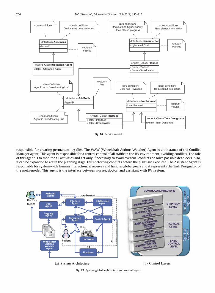
4.4.2. Service modelThe service model is intended to identify the services associated with each agent class or role. As proposed by [10], the
service model table was replaced by a UML class diagram – the missing information (output) was also included as notes tothe services in the diagram. Fig. 16 shows a few services provided by the system.

«protocol»Broadcast
«protocol»RoleSwitch
«protocol»RoleSwitch
«protocol»RoleSwitch
«protocol»RoleSwitch
«protocol»PerformGoal
«protocol»SolveConflict
«protocol»RequestPlan
«protocol»Broadcast
«protocol»MonitorEnvironment
«protocol»MonitorEnvironment
+GeneratePlan()
-High-Level Goal-Conflicted Plan-Low-Level Goal-Improved Plan
«Role»Planner
-Internal World Representation-List of Subscribers
«Role»Broadcaster
+ReadIWR()+GetNextAction()+doAction()
-Internal World Representation-Robot Low-Level Goal-Robot Behaviour
«Role»Reactive
+ReadSensorAndChangeIWR()
-Environment Information-Robot Low-Level Goal-Internal World Representation
«Role»Sensor
-User Requests-Agent Requests-Information-Internal World Representation-Robot Low-Level Goal-Robot High-Level Goal
«Role»Interface
+ReadUserRequest()
-User Requests-Agent Goal Request-Conclict Solving Request-High-Level Goal-Robot Low-Level Goal
«Role»Task Designator
+WriteLogFile()
-Information-Log Files
«Role»Logger
-Robot Low-Level Goal-Robot Odometry Information-Conflict Solving Request
«Role»Conflict Manager
+ActDevice()
-Odometry Information-Status of Device
«Role»Utilitarian
«protocol»MonitorEnvironment
«protocol»Broadcast
Fig. 15. Role and interaction diagram.
202 D.C. Silva et al. / Information Sciences 195 (2012) 190–210
5. Particularizations of the meta-model
This section introduces two instantiations of the meta-model presented in the section above. The two systems are brieflydescribed, and an overview on both architectural and implementation details is given.
5.1. Intelligent Wheelchair platform
Many people with disabilities find it difficult or even impossible to use traditional wheelchairs independently, by man-ually controlling the devices. Intelligent Wheelchairs (IW) are a good solution to assist severely handicapped people who areunable to operate classical electrical wheelchair by themselves in their daily activities. This project is a development plat-form for intelligent wheelchairs. The objectives of this work are to research and develop new methods of navigation andintelligent planning, to solve problems associated with intelligent wheelchairs. This platform will facilitate the developmentand test of new methodologies and techniques concerning IWs, which can be easily integrated into any commercially avail-able electric wheelchair with minor modifications [6].
We believe that new techniques can provide wheelchairs with capabilities for intelligent action planning, autonomousnavigation, and mechanisms to allow the execution, in a semi-autonomous way, of the user’s desires, expressed in ahigh-level language of command. This is achieved through an advanced software control system that goes from simpleshared control, where it ‘‘merely’’ guarantees that the user’s manual control does not take him to dangerous situations (suchas going through holes on the ground, steps and avoiding collisions), to complex high level orders made through voice rec-ognition, path planning, autonomous driving and strategy definition for multiple high level goal achievements.
The platform will allow real and virtual IWs to interact with each other, which makes high complexity tests with a sub-stantial number of devices and wheelchairs possible, representing a reduction in the project costs, since there is no need tobuild a large number of real IW.
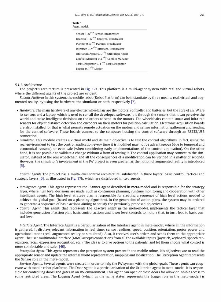
Table 1Agent model.
Sensor 1::N !playSensor, Broadcaster
Reactive 1::N !playReactive, Broadcaster
Planner 0::N !playPlanner, Broadcaster
Interface 0::N !playInterface, Broadcaster
Utilitarian Agent 0::U !playUtilitarian Agent
Conflict Manager 0::C !playConflict Manager
Task Designator 0::1 !playTask Designator
Logger 0::1 !playLogger
D.C. Silva et al. / Information Sciences 195 (2012) 190–210 203
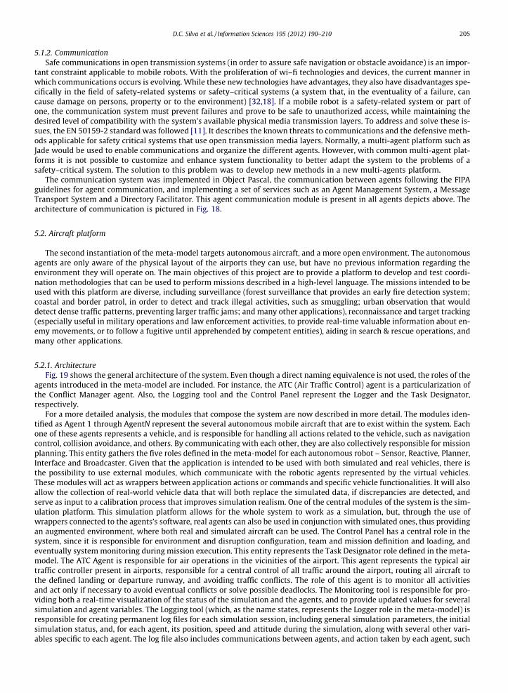
5.1.1. ArchitectureThe project’s architecture is presented in Fig. 17a. This platform is a multi-agent system with real and virtual robots,
where the different agents of the project are evident.Robotic Platform In this system, the mobile robot (Robot Platform) can be instantiate by three means: real, virtual and aug-
mented reality, by using the hardware, the simulator or both, respectively [7].
� Hardware. The main hardware of any electric wheelchair are the motors, controller and batteries, but the core of an IW areits sensors and a laptop, which is used to run all the developed software. It is through the sensors that it can perceive theworld and make intelligent decisions on the orders to send to the motors. The wheelchairs contain sonar and infra-redsensors for object distance detection and encoders on their motors for position calculation. Electronic acquisition boardsare also installed for that is what permits remote actuation on the motors and sensor information gathering and sendingfor the control software. These boards connect to the computer hosting the control software through an RS232/USBconnection.� Simulator. This module creates a virtual world and its main objective is to test the control algorithms. In fact, using the
real environment to test the control application every time it is modified may not be advantageous (due to temporal andeconomical reasons), or even safe (when considering early implementations of the control application). On the otherhand, it is not possible to validate a change without a form of testing it. The control application may connect to the sim-ulator, instead of the real wheelchair, and all the consequences of a modification can be verified in a matter of seconds.However, the simulator’s involvement in the IW project is even greater, as the notion of augmented reality is introduced[5].
Control Agents The project has a multi-level control architecture, subdivided in three layers: basic control, tactical andstrategic layers [6], as illustrated in Fig. 17b, which are distributed in two agents:
� Intelligence Agent. This agent represents the Planner agent described in meta-model and is responsible for the strategylayer, where high level decisions are made, such as continuous planning, runtime monitoring and cooperation with otherintelligent agents. The high level strategy plan is responsible for creating a sequence of high level actions needed toachieve the global goal (based on a planning algorithm). In the generation of action plans, the system may be orderedto generate a sequence of basic actions aiming to satisfy the previously proposed objectives.� Control Agent. This agent, that represents the Reactive agent in the meta-model, implements the tactical layer that
includes generation of action plan, basic control actions and lower level controls to motors that, in turn, lead to basic con-trol level.
Interface Agent. The Interface Agent is a particularization of the Interface agent in meta-model, where all the informationis gathered. It displays relevant information in real time: sensor readings, speed, position, orientation, motor power andoperational mode (real, augmented reality or simulated). Also, it receives user’s orders and sends them to the appropriateagent. The user multimodal interface (MMI) accepts connections from all the available inputs (joystick, keyboard, speech rec-ognition, facial, expression recognition, etc.). The idea is to give options to the patients, and let them choose what control ismore comfortable and safer [40].
Perception Agent. This agent represents the perception system present in the mobile robots. It’s objectives are to read theappropriate sensor and update the internal world representation, mapping and localization. The Perception Agent representsthe Sensor role in the meta-model.
Services Agents. Several agents were created in order to help the IW system with the global goals. These agents can coop-erate with mobile robot platforms. The Door Agent is a particularization of the Utilitarian agent in meta-model. It is respon-sible for controlling doors and gates in an IW environment. This agent can open or close doors for allow or inhibit access tosome restricted areas. The Logging Agent (which, as the name states, represents the Logger role in the meta-model) is
«Role» -Planner«Role» -Broadcaster
«Agent_Class»Planner
«Role» -Interface«Role» -Broadcaster
«Agent_Class»Interface
«Role» -Task Designator«Agent_Class»Task Designator
«Role» -Utilitarian Agent«Agent_Class»Utilitarian Agent
-deviceID«Interface»ActDevice
«pre-condition» «post-condition»Device may be acted upon
«output»Yes/No
-High-Level Goal«Interface»GeneratePlan
«pre-condition»Request has higher priority
than plan in progress
«post-condition»New plan put into action
«output»Plan/No
-AgentID«Interface»AddToList
«pre-condition»Agent not in Broadcasting List
«post-condition»Agent in Broadcasting List
«output»Ack
-User Request«Interface»UserRequest
«pre-condition»User has Privileges
«post-condition»Request put into action
«output»Yes/No
Fig. 16. Service model.
204 D.C. Silva et al. / Information Sciences 195 (2012) 190–210
responsible for creating permanent log files. The WAW (Wheelchair Actions Watcher) Agent is an instance of the ConflictManager agent. This agent is responsible for a central control of all traffic in the IW environment, avoiding conflicts. The roleof this agent is to monitor all activities and act only if necessary to avoid eventual conflicts or solve possible deadlocks. Also,it can be expanded to act in the planning stage, thus detecting conflicts before the plans are executed. The Assistant Agent isresponsible for system-wide human interaction: it receives and handles global goals and it represents the Task Designator ofthe meta-model. This agent is the interface between nurses, doctor, and assistant with IW system.
Fig. 17. System global architecture and control layers.
D.C. Silva et al. / Information Sciences 195 (2012) 190–210 205
5.1.2. CommunicationSafe communications in open transmission systems (in order to assure safe navigation or obstacle avoidance) is an impor-
tant constraint applicable to mobile robots. With the proliferation of wi–fi technologies and devices, the current manner inwhich communications occurs is evolving. While these new technologies have advantages, they also have disadvantages spe-cifically in the field of safety-related systems or safety–critical systems (a system that, in the eventuality of a failure, cancause damage on persons, property or to the environment) [32,18]. If a mobile robot is a safety-related system or part ofone, the communication system must prevent failures and prove to be safe to unauthorized access, while maintaining thedesired level of compatibility with the system’s available physical media transmission layers. To address and solve these is-sues, the EN 50159-2 standard was followed [11]. It describes the known threats to communications and the defensive meth-ods applicable for safety critical systems that use open transmission media layers. Normally, a multi-agent platform such asJade would be used to enable communications and organize the different agents. However, with common multi-agent plat-forms it is not possible to customize and enhance system functionality to better adapt the system to the problems of asafety–critical system. The solution to this problem was to develop new methods in a new multi-agents platform.
The communication system was implemented in Object Pascal, the communication between agents following the FIPAguidelines for agent communication, and implementing a set of services such as an Agent Management System, a MessageTransport System and a Directory Facilitator. This agent communication module is present in all agents depicts above. Thearchitecture of communication is pictured in Fig. 18.
5.2. Aircraft platform
The second instantiation of the meta-model targets autonomous aircraft, and a more open environment. The autonomousagents are only aware of the physical layout of the airports they can use, but have no previous information regarding theenvironment they will operate on. The main objectives of this project are to provide a platform to develop and test coordi-nation methodologies that can be used to perform missions described in a high-level language. The missions intended to beused with this platform are diverse, including surveillance (forest surveillance that provides an early fire detection system;coastal and border patrol, in order to detect and track illegal activities, such as smuggling; urban observation that woulddetect dense traffic patterns, preventing larger traffic jams; and many other applications), reconnaissance and target tracking(especially useful in military operations and law enforcement activities, to provide real-time valuable information about en-emy movements, or to follow a fugitive until apprehended by competent entities), aiding in search & rescue operations, andmany other applications.
5.2.1. ArchitectureFig. 19 shows the general architecture of the system. Even though a direct naming equivalence is not used, the roles of the
agents introduced in the meta-model are included. For instance, the ATC (Air Traffic Control) agent is a particularization ofthe Conflict Manager agent. Also, the Logging tool and the Control Panel represent the Logger and the Task Designator,respectively.
For a more detailed analysis, the modules that compose the system are now described in more detail. The modules iden-tified as Agent 1 through AgentN represent the several autonomous mobile aircraft that are to exist within the system. Eachone of these agents represents a vehicle, and is responsible for handling all actions related to the vehicle, such as navigationcontrol, collision avoidance, and others. By communicating with each other, they are also collectively responsible for missionplanning. This entity gathers the five roles defined in the meta-model for each autonomous robot – Sensor, Reactive, Planner,Interface and Broadcaster. Given that the application is intended to be used with both simulated and real vehicles, there isthe possibility to use external modules, which communicate with the robotic agents represented by the virtual vehicles.These modules will act as wrappers between application actions or commands and specific vehicle functionalities. It will alsoallow the collection of real-world vehicle data that will both replace the simulated data, if discrepancies are detected, andserve as input to a calibration process that improves simulation realism. One of the central modules of the system is the sim-ulation platform. This simulation platform allows for the whole system to work as a simulation, but, through the use ofwrappers connected to the agents’s software, real agents can also be used in conjunction with simulated ones, thus providingan augmented environment, where both real and simulated aircraft can be used. The Control Panel has a central role in thesystem, since it is responsible for environment and disruption configuration, team and mission definition and loading, andeventually system monitoring during mission execution. This entity represents the Task Designator role defined in the meta-model. The ATC Agent is responsible for air operations in the vicinities of the airport. This agent represents the typical airtraffic controller present in airports, responsible for a central control of all traffic around the airport, routing all aircraft tothe defined landing or departure runway, and avoiding traffic conflicts. The role of this agent is to monitor all activitiesand act only if necessary to avoid eventual conflicts or solve possible deadlocks. The Monitoring tool is responsible for pro-viding both a real-time visualization of the status of the simulation and the agents, and to provide updated values for severalsimulation and agent variables. The Logging tool (which, as the name states, represents the Logger role in the meta-model) isresponsible for creating permanent log files for each simulation session, including general simulation parameters, the initialsimulation status, and, for each agent, its position, speed and attitude during the simulation, along with several other vari-ables specific to each agent. The log file also includes communications between agents, and action taken by each agent, such
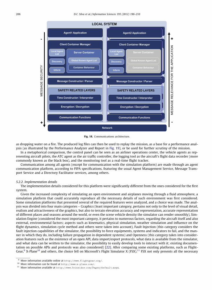
Fig. 18. Communications architecture.
206 D.C. Silva et al. / Information Sciences 195 (2012) 190–210
as dropping water on a fire. The produced log files can then be used to replay the mission, as a base for a performance anal-ysis (as illustrated by the Performance Analyzer and Report in Fig. 19), or be used for further scrutiny of the mission.
In a metaphorical comparison, the control panel can be seen as an airliner operations center, the vehicle agents as rep-resenting aircraft pilots, the ATC agent as the air traffic controller, the logging tool as the aircraft’s flight data recorder (morecommonly known as the black box), and the monitoring tool as a real-time flight tracker.
Communication among all agents (except for communication with the simulation platform) are made through an agentcommunication platform, according to FIPA specifications, featuring the usual Agent Management Service, Message Trans-port Service and a Directory Facilitator services, among others.
5.2.2. Implementation detailsThe implementation details considered for this platform were significantly different from the ones considered for the first
system.Given the increased complexity of simulating an open environment and airplanes moving through a fluid atmosphere, a
simulation platform that could accurately reproduce all the necessary details of such environment was first considered.Some simulation platforms that presented several of the required features were analyzed, and a choice was made. The anal-ysis was divided into four main categories – Graphics (least important category, pertains not only to the level of visual detail,realism and attractiveness of the graphics, but also to terrain elevation accuracy and representation, accurate representationof different places and seasons around the world, or even the scene vehicle density the simulator can render smoothly), Sim-ulation Engine (considered the most important category, it pertains to numerous factors, regarding the aircraft itself and alsoexternal, environmental factors; aspects such as kinematics, physical simulation, weather simulation and influence on theflight dynamics, simulation cycle method and others were taken into account), Fault Injection (this category considers thefault injection capabilities of the simulator, the possibility to force equipments, systems and indicators to fail, and the man-ner in which they do, including failure propagation in dependent systems) and Openness (this category takes into consider-ation features such as the existence of an open API, data import/export protocols, what data is available from the simulator,and what data can be written to the simulator, the possibility to easily develop tools to interact with it; existing documen-tation on possible APIs and protocols was also considered) [22]. After comparing some existing platforms, such as Flight-Gear,9 X-Plane10 and others, the choice fell on Microsoft’s Flight Simulator X (FSX).11 FSX not only presents all the necessary
9 More information available online at http://www.flightgear.org/.10 More information can be found at http://www.x-plane.com/.11 More information available at http://www.fsinsider.com/Pages/default.aspx.
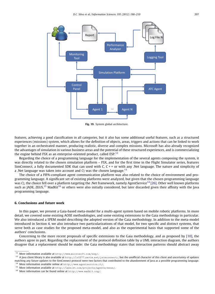
Fig. 19. System global architecture.
D.C. Silva et al. / Information Sciences 195 (2012) 190–210 207
features, achieving a good classification in all categories, but it also has some additional useful features, such as a structuredexperiences (missions) system, which allows for the definition of objects, areas, triggers and actions that can be linked to worktogether in an orchestrated manner, producing realistic, diverse and complex missions. Microsoft has also already recognizedthe advantages of simulation in various business areas and the potential of these structured experiences, and is commercializingthe engine behind FSX as an enterprise-oriented product, called ESP.12
Regarding the choice of a programming language for the implementation of the several agents composing the system, itwas directly related to the chosen simulation platform – FSX, and for the first time in the Flight Simulator series, featuresSimConnect, a fully documented SDK that can used with C, C + + or with any .Net language. The nature and simplicity ofa .Net language was taken into account and C] was the chosen language.13
The choice of a FIPA-compliant agent communication platform was also related to the choice of environment and pro-gramming language. A significant set of existing platforms were analyzed, but given that the chosen programming languagewas C], the choice fell over a platform targeting the .Net framework, namely AgentService14 [26]. Other well known platformssuch as JADE, ZEUS,15 MadKit16 or others were also initially considered, but later discarded given their affinity with the Javaprogramming language.
6. Conclusions and future work
In this paper, we present a Gaia-based meta-model for a multi-agent system based on mobile robotic platforms. In moredetail, we covered some existing AOSE methodologies, and some existing extensions to the Gaia methodology in particular.We also introduced a SPEM model describing the adopted version of the Gaia methodology. In addition to the meta-modelintroduced in Section 4, we also introduce two particularizations of that model, for two specific and distinct systems, thatserve both as case studies for the proposed meta-model, and also as the experimental basis that supported some of theauthors’ conclusions.
Concerning to the more recent proposals of specific extensions to the Gaia methodology, and as proposed by [10], theauthors agree in part. Regarding the replacement of the protocol definition table by a UML interaction diagram, the authorsdisagree that a replacement should be made: the Gaia methodology states that interaction patterns should abstract away
12 More information available at http://www.microsoft.com/esp/.13 A Java client library is also available at http://lc0277.nerim.net/jsimconnect/, but the unofficial character of this client and uncertainty of updates
matching any future updates to the SimConnect protocol were two factors that contributed to the abandonment of Java as a possible programming language.14 More information available online at http://www.agentservice.it/.15 More information available at http://labs.bt.com/projects/agents/zeus/.16 More information can be found online at http://www.madkit.org/.

208 D.C. Silva et al. / Information Sciences 195 (2012) 190–210
from any particular sequence of execution steps [48](page 347); however, the UML diagram could be used as a complement tothe methodology, introduced in the Architectural or Detailed Design stage, to further detail the Interaction Model. Concerningthe replacement of the organizational structure by a UML representation, the authors agree, even though some notes on theUML diagram could be added as to increase the clarity of the model. In what regards to the replacement of the Agent Model bya UML class diagram, the authors agree that a graphical representation gathering all information may be more enlightening,but the model should provide the possibility to specify inherently concurrent or sequential roles (or if two roles cannot beactive at the same time, or if a role must be active in order for another role to become active). Regarding the replacementof the services model tables by a UML class diagram, the authors agree, even though a note could be added to each interfacein order to clearly state the output of the service, thus completing the information. In what concerns to the use of the envi-ronmental model of the preliminary role diagram, preliminary interaction diagram and organizational structure together withthe preliminary role model, preliminary interaction model and organizational structure, the authors believe that the sameinformation is being presented more than once (for instance, environment and roles information is presented on both the firstand second diagrams, and the environment appears again in the third diagram), and as such not all diagrams should be used.Also, it becomes increasingly difficult to maintain information coherency throughout all the models and diagrams, especiallyin larger systems. Regarding the joint use of a role and interaction model to help better visualize these two models, the authorsagree (in fact, this model was included in the methodology, as presented in Section 3).
In respect to the models produced by this methodology, some adaptations had to be made in order to better fit the sys-tems to be modeled. In more detail:
� Regarding the System Sub-Organizations, since most of the systems intended to be modeled do not possess an hierarchi-cal or otherwise structured organization, this model was adapted as to reflect how the different roles may be grouped(logically or physically), possibly in different platforms (mobile or otherwise).� Regarding the Environment model, since these systems operate on the real world, a model representing the environment
would not be suited, and therefore should be included in each particular system implementing this meta-model if par-ticular observations are required.� The Organizational Rules that can be identified as corresponding to all systems being modeled are very few, and therefore
each particularization should provide with an Organizational Rules model that includes the corresponding rules.� The Organizational Structure model is also not suited for a meta-model, since different systems may have different hier-
archical and control structures, or none at all, and therefore each system should provide its own model.
Section 5 presents two models derived from the meta-model, that describe two completely different and independentsystems, the first acting on a more controlled indoor environment, and the second acting on the open space, the implemen-tation choices for each project completely distinct between them. These two distinct systems show that the generic meta-model can be used as a basis for the design of diverse systems, cutting down the time needed to perform several of the tasksinvolved in the process (as opposed from starting from the beginning each time).
Some improvements and future steps identified during this work include further detailing of the Gaia SPEM model. Eventhough the presented model includes only top-level models, more detailed ones can be produced. As for the Gaia process, theadaptations to designing open systems such as the ones depicted in this paper should also be included in a formal model thatcan be reused. These changes in the adopted version of the Gaia methodology could be included as a variation point in themethodology, according to the type of system being modeled [44]. Concerning the meta-model itself, it could also be furtherdetailed, and the inclusion of variability points is also being discussed. These variability points would increase the model’sflexibility and would allow it to be used with a wider range of systems.
As a final conclusion, the authors believe this paper to be a good contribution to the community, in respect to both theGaia methodology in particular and the design of open systems in general. Gaia’s higher level of abstraction, when comparedto other methodologies (other methodologies, and as presented in Section 2, include the definition of implementation detailsin the final stages, while Gaia does not), proved to be an asset when designing the meta-model, and both the SPEM model ofGaia (which provides an easier and faster form for system designers to become familiar with the methodology) and the adap-tations that provide support for the design of open systems (as opposed to organizational-based systems) are believed to begood contributions. Based on the authors’ experience (both on modeling distributed systems and the ones described in thispaper, using the meta-model as a basis) and the feedback from the research laboratory they are inserted in, using the meta-model as a basis has proved to be very helpful in the design of the distinct systems, by significantly reducing most of thecommon design tasks, which also reduces implementation difficulties, while at the same time providing a high-level over-view of the system as a whole.
Acknowledgments
We would like to thank LIACC for providing with all the necessary equipment and for the excellent working conditions.The first author is funded by the Portuguese Foundation for the Science and the Technology under doctoral Grant SFRH/DB/36610/2007 and the second author is supported by a CAPES-Brazil Doctoral Grant. This work was partially supported by FCT/PTDC/EIA/70695/2006 Project – ‘‘ACORD: Adaptive Coordination of Robot Teams’’.

D.C. Silva et al. / Information Sciences 195 (2012) 190–210 209
References
[1] R.C. Arkin, T. Balch, Cooperative multiagent robotic systems, in: D. Kortenkamp, R.P. Bonasso, R. Murphy (Eds.), Artificial Intelligence and MobileRobots: Case Studies of Successful Robot Systems, MIT Press, Cambridge, MA, USA, 1998, pp. 277–296.
[2] B. Bauer, J.P. Müller, J. Odell, Agent UML: a formalism for specifying multiagent software systems, International Journal of Software Engineering andKnowledge Engineering 11 (3) (2001) 207–230.
[3] P. Bayer, M. Svantesson, Comparison of agent-oriented methodologies: analysis and design – MAS-CommonKADS versus Gaia, in: Student Workshopon Agent Programming. Blekinge Institute of Technology, 2001.
[4] F. Bergenti, M.-P. Gleizes, F. Zambonelli (Eds.), Methodologies and Software Engineering for Agent Systems: The Agent-Oriented Software EngineeringHandbook, first ed., Multiagent Systems, Artificial Societies, and Simulated Organizations: International Book Series, Kluwer Academic Publishers,2004.
[5] R.A.M. Braga, P. Malheiro, L.P. Reis, Development of a realistic simulator for robotic intelligent wheelchairs in a hospital environment, in: J. Baltes, M.G.Lagoudakis, T. Naruse, S.S. Ghidary (Eds.), Proceedings of RoboCup 2009: robot soccer world cup XIII, June 30–July 3 2009, Graz, Austria, Lecture Noteson Artificial Intelligence, vol. 5949, Springer, 2010.
[6] R.A.M. Braga, M.R. Petry, A.P. Moreira, L.P. Reis, Intellwheels: a development platform for intelligent wheelchairs for disabled people, in: Proceedings ofthe Fifth International Conference on Informatics in Control, Automation and Robotics (ICINCO 2008), May 11–15, 2008, Funchal, Madeira, Portugal, pp.115–121.
[7] R.A.M. Braga, M.R. Petry, A.P. Moreira, L.P. Reis, Informatics in control, automation and robotics: selected papers from the international conference oninformatics in control, automation and robotics 2008, in: Lecture Notes in Electrical Engineering, Concept and Design of the Intellwheels DevelopmentPlatform for Developing Intelligent Wheelchairs, vol. 37, Springer Berlin, Heidelberg, 2009, pp. 191–203.
[8] P. Bresciani, A. Perini, P. Giorgini, F. Giunchiglia, J. Mylopoulos, Tropos: an agent-oriented software development methodology, Autonomous Agentsand Multi-Agent Systems 8 (3) (2004) 203–236.
[9] F. Carreira, T. Canas, J. Sousa, C. Cardeira, A fuzzy controller for a health services mobile robot, in: IEEE International Symposium on IndustrialElectronics (ISIE 2007), 2007, pp. 3287–3292.
[10] A. Castro, E. Oliveira, The rationale behind the development of an airline operations oontrol centre using gaia-based methodology, International Journalof Agent – Oriented Software Engineering 2 (3) (2008) 350–377.
[11] CENELEC, March 2001. Railway applications communication, signalling and processing systems, Part 2: Safety related communication in opentransmission systems. European Standard EN 50159-2, European Committee for Electrotechnical Standardization, Rue de Stassart 35, B-1050 Brussels.
[12] L. Cernuzzi, T. Juan, L. Sterling, F. Zambonelli, The gaia methodology – basic concepts and extensions, in: F. Bergenti, M.-P. Gleizes, F. Zambonelli (Eds.),Methodologies and Software Engineering for Agent Systems: The Agent-Oriented Software Engineering Handbook, Kluwer Academic Publishing, NewYork, 2004, pp. 69–88.
[13] L. Cernuzzi, F. Zambonelli, Experiencing AUML in the gaia methodology, in: Proceedings of the Sixth International Conference on EnterpriseInformation Systems (ICEIS04), Kluwer Academic Publisher, 2004, pp. 283–288.
[14] K.H. Dam, M. Winikoff, Comparing agent-oriented methodologies, in: Proceedings of the Fifth International Bi-Conference Workshop on Agent-Oriented Information Systems (AOIS 2003), Springer, 2003, pp. 78–93.
[15] S. DeLoach, M.F. Wood, Developing multiagent systems with agenttool, in: Proceedings of the 7th International Workshop on Intelligent Agents VII.Agent Theories Architectures and Languages (ATAL’00), July 7–9, 2000, Springer-Verlag, Boston, MA, 2001, pp. 46–60.
[16] S.A. DeLoach, M.F. Wood, C.H. Sparkman, MultiAgent systems engineering, International Journal of Software Engineering and Knowledge Engineering11 (3) (2001) 231–258.
[17] FIPA, March 2004. Fipa agent management specification. Standard component SC00023K, Foundation for Intelligent Physical Agents, 2, rue Bellot CH-1206 Geneve, Switzerland.
[18] K. Fowler, Mission-critical and safety-critical development, IEEE Instrumentation & Measurement Magazine 7 (4) (2004) 52–59.[19] Future Combat Systems, April 2008. Future Combat Systems (Brigade Combat Team) (FCS (BCT)) System Overview.[20] J.C. Garcfa-Ojeda, A.E. Arenas, J. de Jess Prez-Alczar, Paving the way for implementing multiagent systems: integrating gaia with agent-UML, in: J.P.
Muller, F. Zambonelli (Eds.), Proceedings of the 6th International Workshop on Agent-Oriented Software Engineering (AOSE 2005), 25–26 July 2005,Springer-Verlag, Utrecht, The Netherlands, 2006, pp. 179–189.
[21] A. Garro, P. Turci, Meta-Model Sources: Gaia. Tech. rep., Foundation for Intelligent Physical Agents, 2003.[22] R. Gimenes, D.C. Silva, L.P. Reis, E. Oliveira, Flight Simulation Environments Applied to Agent-Based Autonomous UAVs, in: J. Cordeiro, J. Filipe (Eds.),
Proceedings of the Tenth International Conference on Enterprise Information Systems (ICEIS 2008), Barcelona, Spain, June 12–16, 2008. pp. 243–246.[23] P. Giorgini, M. Kolp, J. Mylopoulos, M. Pistore, The tropos methodology: an overview, in: Methodologies and Software Engineering for Agent Systems,
Kluwer Academic Press, 2003, p. 505.[24] F. Giunchiglia, J. Mylopoulos, A. Perini, The tropos software development methodology: processes, models and diagrams, in: F. Giunchiglia, J. Odell, G.
Weiß (Eds.), Third International Workshop on Agent-Oriented Software Engineering (AOSE 2002) Revised Papers and Invited Contributions, Springer,2002, pp. 162–173.
[25] J. Gonzalez-Palacios, M. Luck, Extending gaia with agent design and iterative development, in: M. Luck, L. Padgham (Eds.), 8th International Workshopon Agent-Oriented Software Engineering (AOSE 2007), May 14, 2007, Springer, Honolulu, HI, USA, 2008, pp. 16–30. Revised Selected Papers.
[26] A. Grosso, A. Boccalatte, M. Coccoli, A. Gozzi, An agent programming framework based on the C] language and the CLI, in: Proceedings of the 1stInternational Workshop on C] and .NET Technologies on Algorithms, Computer Graphics, Visualization, Distributed and WEB Computing, Plzen, CzechRepublic, February 6–8, 2003, pp. 13–20.
[27] C.A. Iglesias, M. Garijo, J. Centeno-González, A survey of agent-oriented methodologies, in: J.P. Müller, M.P. Singh, A.S. Rao (Eds.), Proceedings of theFifth International Workshop on Agent Theories, Architectures, and Languages (ATAL ’98), July 4–7, 1998, Lecture Notes in Computer Science, Springer,Paris, France, 1998, pp. 317–330.
[28] C.A. Iglesias, M. Garijo, A survey of agent-oriented methodologies, in: Proceedings of the Fifth International Workshop on Agent Theories,Architectures, and Languages (ATAL’98), July 1998, Springer-Verlag, Paris, France, 1999, pp. 317–330.
[29] T. Juan, A. Pearce, L. Sterling, Roadmap: extending the gaia methodology for complex open systems, in: Proceedings of the First International JointConference on Autonomous Agents and Multiagent Aystems (AAMAS ’02), ACM, New York, NY, USA, 2002, pp. 3–10.
[30] S. Kim, Autonomous Cleaning robot: roboking system integration and overview, in: Proceedings of the IEEE International Conference on Robotics andAutomation, 2004 (ICRA ’04), vol. 5, April–1 May 2004, pp. 4437–4441.
[31] B. Krose, R. Bunschoten, S. Hagen, B. Terwijn, N. Vlassis, Household robots look and learn: environment modeling and localization from anomnidirectional vision system, IEEE Robotics & Automation Magazine 11 (4) (2004) 45–52.
[32] T. Malm, J. Hérard, J. Bøegh, M. Kivipuro, Validation of Safety-Related Wireless Machine Control Systems. NT Tech Report TR 605, Nordic InnovationCentre, Stensberggata 25, NO-0170 Oslo, Norway, March 2007.
[33] P. Moraitis, N.I. Spanoudakis, The Gaia2Jade process for multi-agent systems development, Applied Artificial Intelligence 20 (2–4) (2006) 251–273.[34] Object Management Group, January 2005. Software Process Engineering Metamodel Specification. Specification formal/05-01-06, Object Management
Group.[35] Object Management Group, April 2008. Software & Systems Process Engineering Meta-Model Specification. Specification formal/2008-04-01, Object
Management Group.
210 D.C. Silva et al. / Information Sciences 195 (2012) 190–210
[36] J. Odell, H.V.D. Parunak, B. Bauer, Representing agent interaction protocols in UML, in: P. Ciancarini, M. Wooldridge (Eds.), First InternationalWorkshop on Agent-Oriented Software Engineering (AOSE 2000), Limerick, Ireland, June 10, 2000, Springer-Verlag, New York Inc., 2001, pp. 121–140.Revised Papers.
[37] L. Padgham, J. Thangarajah, M. Winikoff, The prometheus design tool – a conference management system case study, in: 8th International Workshopon Agent-Oriented Software Engineering (AOSE 2007), Honolulu, Hawaii, USA, May 14, 2007, pp. 197–211 (Revised Selected Papers).
[38] L. Padgham, M. Winikoff, Prometheus: a methodology for developing intelligent agents, in: F. Giunchiglia, J. Odell, G. Weiß (Eds.), Third InternationalWorkshop on Agent-Oriented Software Engineering (AOSE 2002), Revised Papers and Invited Contributions, Springer, 2002, pp. 174–185.
[39] L. Padgham, M. Winikoff, Developing Intelligent Agent Systems: a Practical Guide Wiley Series in Agent Technology, 1st ed., John Wiley and Sons, 2004.[40] L.P. Reis, R.A.M. Braga, M. Sousa, A.P. Moreira, IntellWheels MMI: a flexible interface for an intelligent wheelchair, in: J. Baltes, M.G. Lagoudakis, T.
Naruse, S.S. Ghidary (Eds.), Proceedings of RoboCup 2009: Robot Soccer World Cup XIII, June 30–July 3 2009, Graz, Austria, Lecture Notes on ArtificialIntelligence, vol. 5949, Springer, 2010.
[41] L. Sterling, K. Taveter, The Art of Agent-Oriented Modeling, Intelligent Robotics and Autonomous Agents, The MIT Press., 2009.[42] A. Sturm, O. Shehory, A comparative evaluation of agent-oriented methodologies, in: F. Bergenti, M.-P. Gleizes, F. Zambonelli (Eds.), Methodologies
and Software Engineering for Agent Systems: The Agent-Oriented Software Engineering Handbook, Kluwer Academic Publishing, New York, 2004, pp.127–149.
[43] G. Trivino, L. Mengual, A. van der Heide, Towards an architecture for semiautonomous robot telecontrol systems, Information Sciences 179 (23) (2009)3973–3984.
[44] D.L. Webber, H. Gomaa, Modeling variability in software product lines with the variation point model, Science of Computer Programming 53 (3) (2004)305–331.
[45] M. Winikoff, L. Padgham, The prometheus methodology, in: F. Bergenti, M.-P. Gleizes, F. Zambonelli (Eds.), Methodologies and Software Engineeringfor Agent Systems: The Agent-Oriented Software Engineering Handbook, Kluwer Academic Publishing, New York, 2004, pp. 217–234.
[46] M.F. Wood, S.A. DeLoach, An overview of the multiagent systems engineering methodology, in: P. Ciancarini, M. Wooldridge (Eds.), Proceedings of theFirst International Workshop on Agent-Oriented Software Engineering (AOSE 2000), June 2000, Springer-Verlag, 2001, pp. 207–221.
[47] M. Wooldridge, N.R. Jennings, D. Kinny, The gaia methodology for agent-oriented analysis and design, Journal of Autonomous Agents and Multi-AgentSystems 3 (3) (2000) 285–312.
[48] F. Zambonelli, N.R. Jennings, M. Wooldridge, Developing mmultiagent systems: the gaia methodology, ACM Transactions on Software EngineeringMethodologies 12 (3) (2003) 317–370.
[49] Y. Zhan, H. Liu, Z. Liu, Y. Luo, J. Dong, The goods-flowing system AGV technology of Yuxi cigarette factory and the developmental research of AGVnationalization technology, in: Proceedings of the IEEE International Vehicle Electronics Conference, vol. 1, 1999 (IVEC ’99), pp. 425–428.
[50] S. Zieba, P. Polet, F. Vanderhaegen, Using Adjustable autonomy and humanmachine cooperation to make a humanmachine system resilient applicationto a ground robotic system, Information Sciences 181 (3) (2011) 379–397.