design of tesla s two -phase inductor - etfblindel.etfbl.net/2014/resources/proceedings_2014/... ·...
TRANSCRIPT
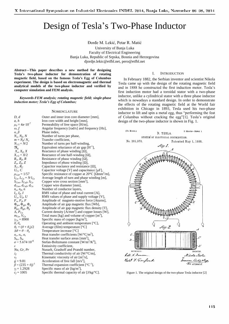
Figure 1. The original design of the two-phase Tesla inductor [2]
Design of Tesla’s Two-Phase Inductor
Đorđe M. Lekić, Petar R. Matić
University of Banja Luka
Faculty of Electrical Engineering
Banja Luka, Republic of Srpska, Bosnia and Herzegovina
[email protected], [email protected]
Abstract—This paper describes a new method for designing
Tesla’s two-phase inductor for demonstration of rotating
magnetic field, based on the famous Tesla’s Egg of Columbus
experiment. The design is based on electromagnetic and thermal
analytical models of the two-phase inductor and verified by
computer simulation and FEM analysis.
Keywords-FEM analysis; rotating magnetic field; single-phase
induction motor; Tesla’s Egg of Columbus;
NOMENCLATURE
D, d Outer and inner iron core diameter [mm], a, h Iron core width and height [mm], μ0 = 4π·10-7 Permeability of free space [H/m], ω, f Angular frequency [rad/s] and frequency [Hz], α, β Phase index, Nα, Nβ, N Number of turns per phase, m = Nβ/ Nα Transfer coefficient, N1/2 = N/2 Number of turns per half-winding, Rg Equivalent reluctance of air gap [H-1], Xα, Xβ, X Reactance of phase winding [Ω], X1/2 = X/2 Reactance of one half-winding [Ω], Rα, Rβ, R Resistance of phase winding [Ω], Zα, Zβ, Z Impedance of phase winding [Ω], XC, RC Capacitor reactance and resistance [Ω], UC, C Capacitor voltage [V] and capacitance [μF], ρCu0 = 1/57 Specific resistance of copper at 20°C [Ωmm2/m], lCu, LCu = N·lCu Average length of turn and phase winding [m], SCuα, SCuβ, SCu Copper wire cross section [mm2], dCuα, dCuβ, dCu Copper wire diameter [mm], nα, nβ, n Number of conductor layers, Iα, Iβ, I RMS value of phase and total current [A], Uα, Uβ, U RMS values of phase and supply voltage [V], Fα, Fβ, F Amplitude of magneto-motive force [Aturns], Φgα, Φgβ, Φg Amplitude of air gap magnetic flux [Wb], Bgα, Bgβ, Bg Amplitude of air gap magnetic flux density [T], Δ, PCu Current density [A/mm2] and copper losses [W], mCu, VCu Total mass [kg] and volume of copper [m3], γCu = 8900 Specific mass of copper [kg/m3], θ, θa Operating and ambient temperature [°C], θf = (θ + θa)/2 Average (film) temperature [°C] ∆θ = θ – θa Temperature increase [°C] αc, αr, αt Heat transfer coefficients [W/°C/m2], Shc, Shr Heat transfer surface areas [mm2], σ = 5.674∙10-8 Stefan-Boltzmann constant [W/m2/K4], ε Emissivity coefficient, Nu, Gr, Pr Nusselt, Grashoff and Prandtl number, λf Thermal conductivity of air [W/°C/m], νf Kinematic viscosity of air [m2/s], g = 9.81 Acceleration of free fall [m/s2], β = (235 + θf)
-1 Thermal expansion coefficient [°C-1], γf = 1.2928 Specific mass of air [kg/m3], cf = 1005 Specific thermal capacity of air [J/kg/°C].
I. INTRODUCTION
In February 1882, the Serbian inventor and scientist Nikola Tesla came up with the design of the rotating magnetic field and in 1888 he constructed the first induction motor. Tesla’s first induction motor had a toroidal stator with a two-phase inductor, unlike a cylindrical stator with a three phase inductor which is nowadays a standard design. In order to demonstrate the effects of the rotating magnetic field at the World fair exhibition in Chicago in 1893, Tesla used his two-phase inductor to lift and spin a metal egg, thus “performing the feat of Columbus without cracking the egg”[1]. Tesla’s original design of the two-phase inductor is shown in Fig. 1.
X International Symposium on Industrial Electronics INDEL 2014, Banja Luka, November 0608, 2014
115
F
ФFe ФFe
Фg
F
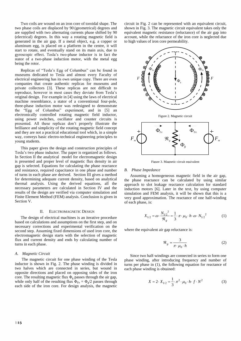
Figure 2. Magnetic circuit
gF
m
gФ
FeФ ФFe
Fm
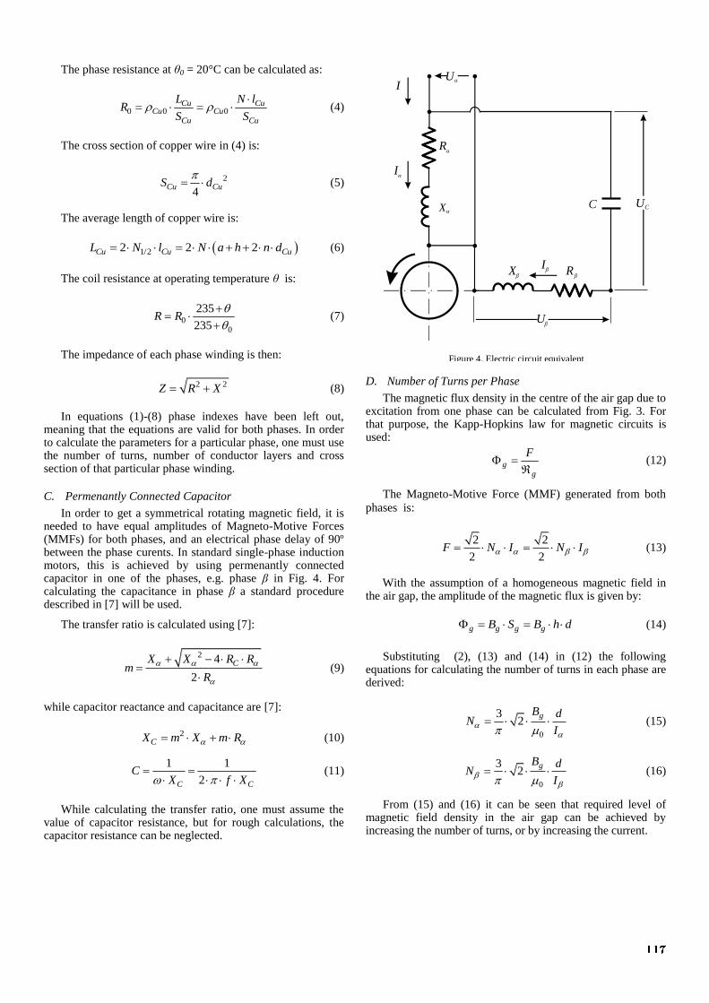
Figure 3. Magnetic circuit equivalent
Two coils are wound on an iron core of toroidal shape. The two phase coils are displaced by 90
(geometrical) degrees and
are supplied with two alternating currents phase shifted by 90
(electrical) degrees. In this way a rotating magnetic field is generated in the air gap. If a metal object, e.g. a copper or aluminum egg, is placed on a platform in the centre, it will start to rotate, and eventually stand on its main axis, due to gyroscopic effect. Tesla’s two-phase inductor is in fact the stator of a two-phase induction motor, with the metal egg being the rotor.
Replicas of “Tesla’s Egg of Columbus” can be found in museums dedicated to Tesla and almost every Faculty of electrical engineering has its own unique copy. There are even companies that create authentic replicas for museums and private collectors [3]. These replicas are not difficult to reproduce, however in most cases they deviate from Tesla’s original design. For example in [4] using the laws of electrical machine resemblance, a stator of a conventional four-pole, three-phase induction motor was redesigned to demonstrate the “Egg of Columbus” experiment, and in [5] an electronically controlled rotating magnetic field inductor, using power switches, oscillator and counter circuits is presented. All these replicas don’t properly illustrate the brilliance and simplicity of the rotating magnetic field concept and they are not a practical educational tool which, in a simple way, conveys basic electro-technical engineering principles to young students.
This paper gives the design and construction principles of Tesla’s two phase inductor. The paper is organized as follows. In Section II the analytical model for electromagnetic design is presented and proper level of magnetic flux density in air gap is selected. Equations for calculating the phase reactance and resistance, required capacitance in one phase and number of turns in each phase are derived. Section III gives a method for determining adequate current density, based on analytical thermal analysis. Using the derived equations, all the necessary parameters are calculated in Section IV and the results of the design are verified via computer simulation and Finite Element Method (FEM) analysis. Conclusion is given in Section V.
II. ELECTROMAGNETIC DESIGN
The design of electrical machines is an iterative procedure based on calculations and assumptions on the first step, and on necessary corrections and experimental verification on the second step. Assuming fixed dimensions of used iron core, the electromagnetic design starts with the selection of magnetic flux and current density and ends by calculating number of turns in each phase.
A. Magnetic Circuit
The magnetic circuit for one phase winding of the Tesla inductor is shown in Fig. 2. The phase winding is divided in two halves which are connected in series, but wound in opposite directions and placed on opposing sides of the iron core. The resulting magnetic flux Φg passes through the air gap, while only half of the resulting flux ΦFe = Φg/2 passes through each side of the iron core. For design analysis, the magnetic
circuit in Fig. 2 can be represented with an equivalent circuit, shown in Fig. 3. The magnetic circuit equivalent takes only the equivalent magnetic resistance (reluctance) of the air gap into account, while the reluctance of the iron core is neglected due to high values of iron core permeability.
B. Phase Impedance
Assuming a homogeneous magnetic field in the air gap, the phase reactance can be calculated by using similar approach to slot leakage reactance calculation for standard induction motors [6]. Later in the text, by using computer simulation and FEM analysis, it will be shown that this is a very good approximation. The reactance of one half-winding of each phase, is:
2
21/21/2 0 1/2
1
3g
NX h N
(1)
where the equivalent air gap reluctance is:
0
3g
h
(2)
Since two half-windings are connected in series to form one phase winding, after introducing frequency and number of turns per phase in (1), the following equation for reactance of each phase winding is obtained:
2 21/2 0
12
3X X h f N (3)
116
Rβ
Rα
Xα
Xβ
C
Uα
Uβ
I
Iα
Iβ
UC
Figure 4. Electric circuit equivalent
The phase resistance at θ0 = 20°C can be calculated as:
0 0 0Cu Cu
Cu CuCu Cu
L N lR
S S
(4)
The cross section of copper wire in (4) is:
2
4Cu CuS d
(5)
The average length of copper wire is:
1/22 2 2Cu Cu CuL N l N a h n d (6)
The coil resistance at operating temperature θ is:
00
235
235R R
(7)
The impedance of each phase winding is then:
2 2Z R X (8)
In equations (1)-(8) phase indexes have been left out, meaning that the equations are valid for both phases. In order to calculate the parameters for a particular phase, one must use the number of turns, number of conductor layers and cross section of that particular phase winding.
C. Permenantly Connected Capacitor
In order to get a symmetrical rotating magnetic field, it is needed to have equal amplitudes of Magneto-Motive Forces (MMFs) for both phases, and an electrical phase delay of 90º between the phase curents. In standard single-phase induction motors, this is achieved by using permenantly connected capacitor in one of the phases, e.g. phase β in Fig. 4. For calculating the capacitance in phase β a standard procedure described in [7] will be used.
The transfer ratio is calculated using [7]:
2 4
2
CX X R Rm
R
(9)
while capacitor reactance and capacitance are [7]:
2CX m X m R (10)
1 1
2C C
CX f X
(11)
While calculating the transfer ratio, one must assume the value of capacitor resistance, but for rough calculations, the capacitor resistance can be neglected.
D. Number of Turns per Phase
The magnetic flux density in the centre of the air gap due to excitation from one phase can be calculated from Fig. 3. For that purpose, the Kapp-Hopkins law for magnetic circuits is used:
gg
F
(12)
The Magneto-Motive Force (MMF) generated from both
phases is:
2 2
2 2F N I N I (13)
With the assumption of a homogeneous magnetic field in the air gap, the amplitude of the magnetic flux is given by:
g g g gB S B h d (14)
Substituting (2), (13) and (14) in (12) the following equations for calculating the number of turns in each phase are derived:
0
32
gB dN
I
(15)
0
32
gB dN
I
(16)
From (15) and (16) it can be seen that required level of magnetic field density in the air gap can be achieved by increasing the number of turns, or by increasing the current.
117

The required level of magnetic field density is determined from the condition that it only has to spin the egg, and therefore can be much lower than as in conventional electric machines. This level is determined by analyzing a prototype. The results of the experiments show that for rotating magnetic field demonstration, a magnetic flux density of 5-10 mT is large enough to lift and spin a smaller metal egg. Heaving this range of values in mind, the design problem is to select the appropriate number of turns for each phase winding in order to obtain required magnetic flux density without overheating the coils due to large currents needed to generate this flux density in the large air gap.
If a standard value of copper wire diameter for phase α is selected, with a proper value for current density without overheating, the phase current and the number of turns in phase α, using (15) can be calculated. After the number of turns is found, the reactance and resistance of phase α using (3) and (4) and the required transfer ratio using (9) can be calculated. In that case, phase current and number of turns in phase β is further calculated as:
I
Im
(17)
N m N (18)
From (17) the diameter and cross section of copper wire in phase β should be adopted to the closest standard values. Since the core has fixed dimensions, it must be must ensured that there is enough space to place both phase windings on the core. The windings will fit on the core if they are wounded in n layers, where n is calculated for each phase independently using:
2 CuN d
nd
(19)
where the first larger integer value should be adopted. At the end the number of turns for phase β is calculated by using the same equations as for phase α.
III. THERMAL DESIGN
Current density of conventional induction motors is typically in the range 3-8 A/mm
2 [6]. Current density
determines the cross section of copper wire, or in other words, the total mass of copper used to wound the inductor. Since the losses depend on the value of current density, the steady state temperature of the windings also depends on current density. In order to prevent overheating, a thermal model is used to select the required value of current density.
A. Coper Losses
The design is based on requirement that the steady state temperature of windings does not exceed 80ºC. Since the magnetic flux density is in the range of 5-10 mT, the iron losses can be neglected, and only the copper losses are considered.
The total copper losses in both phases at operating temperature θ are:
2 2 22CuP R I R I R I (20)
If it is assumed that operating temperature should be θ = 80ºC, the resistance should be increased using (7) and the following equation for copper losses in common electrical machines is obtained [6]:
2 22.42CuCu Cu Cu
Cu
mP m
(21)
where Δ is given in A/mm2 and total mass of copper is:
Cu Cu Cu Cu Cu Cu Cu Cum V L S L S (22)
From (21) the losses per cubic meter of copper depend only on the current density:
2 22.42 21538CuCu
Cu
P
V (23)
If the copper losses from (21) are combined with (4) and (15) or (16), the following equation is derived:
0
6 2 Cu CuCu g g
d lP B k B
(24)
in which k is a constructive constant which depends on characteristics of used materials and core dimensions. From (24) the characteristic product of magnetic flux and current density can be found which will provide that copper losses don’t lead to overheating.
B. Current Density
The allowed copper loss can be calculated using Newton’s law of cooling [6,8]:
max t hcP S (25)
where convection and radiation heat transfer surface areas and total heat transfer coefficient are:
2 244
hc hrS S h d h D d D d
(26)
hrt c r
hc
S
S (27)
Using (25) the copper losses which will lead to steady state temperature rise of θ = 80ºC can be calculated, and after that, using (24) the maximum allowed current density for a given value of magnetic flux density is calculated.
118
70 75 80 85 90 95 1002
2.5
3
3.5
4
4.5
5
5.5
oC
A
/mm
2
a1
= 15 oC
a2
= 20 oC
a3
= 25 oC
a4
= 30 oC
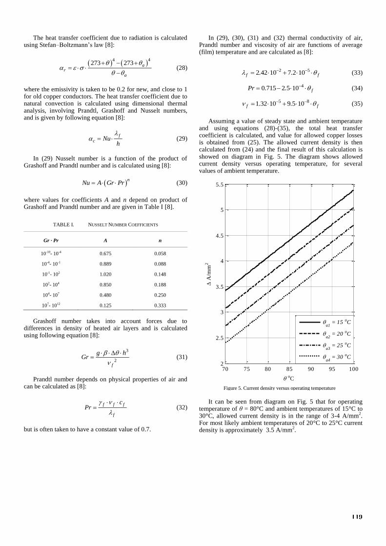
Figure 5. Current density versus operating temperature
The heat transfer coefficient due to radiation is calculated using Stefan–Boltzmann’s law [8]:
44273 273 a
ra
(28)
where the emissivity is taken to be 0.2 for new, and close to 1 for old copper conductors. The heat transfer coefficient due to natural convection is calculated using dimensional thermal analysis, involving Prandtl, Grashoff and Nusselt numbers, and is given by following equation [8]:
f
c Nuh
(29)
In (29) Nusselt number is a function of the product of Grashoff and Prandtl number and is calculated using [8]:
n
Nu A Gr Pr (30)
where values for coefficients A and n depend on product of Grashoff and Prandtl number and are given in Table I [8].
TABLE I. NUSSELT NUMBER COEFFICIENTS
Gr ∙ Pr A n
10-10- 10-4 0.675 0.058
10-4- 10-1 0.889 0.088
10-1- 102 1.020 0.148
102- 104 0.850 0.188
104- 107 0.480 0.250
107- 1012 0.125 0.333
Grashoff number takes into account forces due to
differences in density of heated air layers and is calculated using following equation [8]:
3
2f
g hGr
(31)
Prandtl number depends on physical properties of air and can be calculated as [8]:
f f f
f
cPr
(32)
but is often taken to have a constant value of 0.7.
In (29), (30), (31) and (32) thermal conductivity of air, Prandtl number and viscosity of air are functions of average (film) temperature and are calculated as [8]:
2 52 42 10 7 2 10f f. . (33)
40 715 2 5 10 fPr . . (34)
5 81 32 10 9 5 10f f. . (35)
Assuming a value of steady state and ambient temperature and using equations (28)-(35), the total heat transfer coefficient is calculated, and value for allowed copper losses is obtained from (25). The allowed current density is then calculated from (24) and the final result of this calculation is showed on diagram in Fig. 5. The diagram shows allowed current density versus operating temperature, for several values of ambient temperature.
It can be seen from diagram on Fig. 5 that for operating temperature of θ = 80°C and ambient temperatures of 15°C to 30°C, allowed current density is in the range of 3-4 A/mm
2.
For most likely ambient temperatures of 20°C to 25°C current density is approximately 3.5 A/mm
2.
119
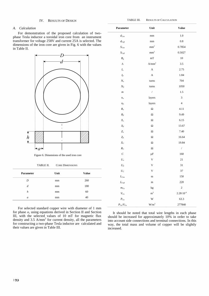
Figure 6. Dimensions of the used iron core
IV. RESULTS OF DESIGN
A. Calculation
For demonstration of the proposed calculation of two-phase Tesla inductor a toroidal iron core from an instrument transformer for voltage 258V and current 25A is selected. The dimensions of the iron core are given in Fig. 6 with the values in Table II.
TABLE II. CORE DIMENSIONS
Parameter Unit Value
D mm 260
d mm 180
h mm 60
a mm 40
For selected standard copper wire with diameter of 1 mm for phase α, using equations derived in Section II and Section III, with the selected values of 10 mT for magnetic flux density and 3.5 A/mm
2 for current density, all the parameters
for constructing a two-phase Tesla inductor are calculated and their values are given in Table III.
TABLE III. RESULTS OF CALCULATION
Parameter Unit Value
dCuα mm 1.0
dCuβ mm 0.8
SCuα mm2 0.7854
SCuβ mm2 0.5027
Bg mT 10
∆ A/mm2 3.5
Iα A 2.75
Iβ A 1.84
Nα turns 704
Nβ turns 1050
m / 1.5
nα layers 3
nβ layers 4
Rα Ω 4.11
Rβ Ω 9.49
Xα Ω 6.15
Xβ Ω 13.67
Zα Ω 7.40
Zβ Ω 16.64
XC Ω 19.84
RC Ω /
C µF 160
Uα V 21
Uβ V 31
UC V 37
LCuα m 150
LCuβ m 220
mCu kg 2
VCu m3 2.28∙10-4
PCu W 63.3
PCu/VCu W/m3 277840
It should be noted that total wire lengths in each phase should be increased for approximately 10% in order to take into account side connections and terminal connections. In this way, the total mass and volume of copper will be slightly increased.
120
Density Plot: |B|, Tesla
5.822e-002 : >6.125e-002
5.519e-002 : 5.822e-002
5.216e-002 : 5.519e-002
4.913e-002 : 5.216e-002
4.610e-002 : 4.913e-002
4.308e-002 : 4.610e-002
4.005e-002 : 4.308e-002
3.702e-002 : 4.005e-002
3.399e-002 : 3.702e-002
3.096e-002 : 3.399e-002
2.793e-002 : 3.096e-002
2.490e-002 : 2.793e-002
2.188e-002 : 2.490e-002
1.885e-002 : 2.188e-002
1.582e-002 : 1.885e-002
1.279e-002 : 1.582e-002
9.761e-003 : 1.279e-002
6.733e-003 : 9.761e-003
3.704e-003 : 6.733e-003
<6.754e-004 : 3.704e-003
Figure 7. Magnetic flux density plot for phase α
Density Plot: |B|, Tesla
5.388e-002 : >5.667e-002
5.108e-002 : 5.388e-002
4.829e-002 : 5.108e-002
4.549e-002 : 4.829e-002
4.269e-002 : 4.549e-002
3.990e-002 : 4.269e-002
3.710e-002 : 3.990e-002
3.430e-002 : 3.710e-002
3.151e-002 : 3.430e-002
2.871e-002 : 3.151e-002
2.592e-002 : 2.871e-002
2.312e-002 : 2.592e-002
2.032e-002 : 2.312e-002
1.753e-002 : 2.032e-002
1.473e-002 : 1.753e-002
1.193e-002 : 1.473e-002
9.138e-003 : 1.193e-002
6.342e-003 : 9.138e-003
3.546e-003 : 6.342e-003
<7.495e-004 : 3.546e-003
Figure 8. Magnetic flux density plot for phase β
|B|, Tesla
Length, mm
0.013
0.0125
0.012
0.0115
0.011
0.0105
0.01
0 50 100 150
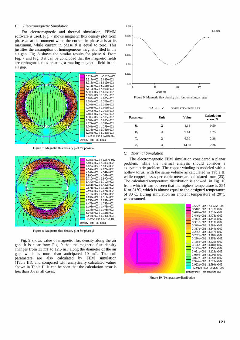
Figure 9. Magnetic flux density distribution along air gap
Density Plot: Temperature (K)
3.542e+002 : >3.575e+002
3.510e+002 : 3.542e+002
3.478e+002 : 3.510e+002
3.446e+002 : 3.478e+002
3.413e+002 : 3.446e+002
3.381e+002 : 3.413e+002
3.349e+002 : 3.381e+002
3.317e+002 : 3.349e+002
3.285e+002 : 3.317e+002
3.252e+002 : 3.285e+002
3.220e+002 : 3.252e+002
3.188e+002 : 3.220e+002
3.156e+002 : 3.188e+002
3.123e+002 : 3.156e+002
3.091e+002 : 3.123e+002
3.059e+002 : 3.091e+002
3.027e+002 : 3.059e+002
2.994e+002 : 3.027e+002
2.962e+002 : 2.994e+002
<2.930e+002 : 2.962e+002
Figure 10. Temperature distribution
B. Electromagnetic Simulation
For electromagnetic and thermal simulation, FEMM software is used. Fig. 7 shows magnetic flux density plot from phase α, at the moment when the current in phase α is at its maximum, while current in phase β is equal to zero. This justifies the assumption of homogeneous magnetic filed in the air gap. Fig. 8 shows the similar results for phase β. From Fig. 7 and Fig. 8 it can be concluded that the magnetic fields are orthogonal, thus creating a rotating magnetic field in the air gap.
Fig. 9 shows value of magnetic flux density along the air gap. It is clear from Fig. 9 that the magnetic flux density changes from 11 mT to 12.5 mT along the diameter of the air gap, which is more than anticipated 10 mT. The coil parameters are also calculated by FEM simulation (Table III), and compared with analytically calculated values shown in Table II. It can be seen that the calculation error is less than 3% in all cases.
TABLE IV. SIMULATION RESULTS
Parameter Unit Value Calculation
error %
Rα Ω 4.13 0.50
Rβ Ω 9.61 1.25
Xα Ω 6.30 2.38
Xβ Ω 14.00 2.36
C. Thermal Simulation
The electromagnetic FEM simulation considered a planar problem, while the thermal analysis should consider a axisymmetric problem. The copper winding is modeled with a hollow torus, with the same volume as calculated in Table II, while copper losses per cubic meter are calculated from (23). The calculated temperature distribution is showed in Fig. 10 from which it can be seen that the highest temperature is 354 K or 81°C, which is almost equal to the designed temperature of 80°C. During simulation an ambient temperature of 20°C was assumed.
121

It may seem that the model shown in Fig. 10 is oversimplified, but with current level of design, without experimental verification, it would be unreliable to assume special insulation types for conductors and special wooden or metal platforms for the metal egg to spin on them which may influence the basic calculation.
V. CONCLUSIONS
In this paper a full design procedure for calculating the parameters of Tesla’s two-phase inductor is explained. Starting from basic concepts of electrical machine design, a new method dedicated to special machines with large air gaps and toroidal inductors is developed. The main problem of the proposed design procedure is found to be the selection of magnetic flux density and current density values. While magnetic flux density, required to lift a small metal egg, is determined experimentally, the value for current density is selected as a result of detailed thermal analysis. Even such analysis implies complicated set of equations and is parameter sensitive, it is shown that for reasonable values of operating and ambient temperature, the current density is found to be in a relatively small range of values. It is shown that the analytical model gives very similar results as the FEM computer simulation. It should also be noted that the total copper losses of such a device are around 60 W which is equivalent to a light bulb. Even it seems that the larger values
of current densities can be allowed without overheating the winding, the FEM simulation showed that with only 60 W of losses the temperature rise is close to given 80°C limit. The next step would be to build the prototype based on the proposed calculation. Only by experimental verification, the the design process will be completed.
REFERENCES
[1] Tesla universe, “Tesla’s Egg of Columbus” [Online]. Available: http:// www.teslauniverse.com/nikola-tesla-article-teslas-egg-of-columbus
[2] N. Tesla, “System of Electrical Distribution,” U.S. Patent 0 381 970 May 1, 1888.
[3] RT17, “Tesla’s Egg of Columbus–Production of working replicas” [Online]. Available: http://www.rt17.hr/teslas-egg-of-columbus/
[4] P. Matić, M. Milanković, G. Kondić, M. Radivojević, “An laboratory model for induction machine practice (in Serbian),” in Proc. Symposium Industrial Electronics INDEL 2004, Banja Luka, Republic of Srpska – Bosnia and Herzegovina, Sep. 11-12, 2004, Vol. V, pp. 65-68
[5] D. Jagodić, A. Ilišković, „Forming of rotary magnetic field (in Serbian),“ in Proc. Symposium Industrial Electronics INDEL 1997, Banja Luka, Republic of Srpska – Bosnia and Herzegovina, Sep. 24-26, 1997, Vol. 1, pp. 154-158
[6] V. Petrović, Uput u proračun asinhronog motora, vol. I. Beograd Naučna knjiga, 1974, pp. 81-88
[7] B. Mitraković, Asinhrone mašine, vol. IV. Beograd Naučna knjiga, 1989, pp. 105
[8] V. Morgan, Thermal behaviour of electrical conductors, vol. I. Taunton Research Studies Press, 1991
122