design of spillway tainter gates
TRANSCRIPT
CECW-ET
Engineer Manual1110-2-2702
Department of the ArmyU.S. Army Corps of Engineers
Washington, DC 20314-1000
EM 1110-2-2702
1 January 2000
Engineering and Design
DESIGN OF SPILLWAY TAINTER GATES
Distribution Restriction StatementApproved for public release;
distribution is unlimited.
EM 1110-2-27021 January 2000
US Army Corpsof Engineers
ENGINEER MANUAL
Design of Spillway Tainter Gates
ENGINEERING AND DESIGN
DEPARTMENT OF THE ARMY EM 1110-2-2702U.S. Army Corps of Engineers
CECW-ET Washington, DC 20314-1000
ManualNo. 1110-2-2702 1 January 2000
Engineering and DesignDESIGN OF SPILLWAY TAINTER GATES
1. Purpose. This manual provides guidance for the design, fabrication, and inspection of spillwaytainter gates, trunnion girder, and trunnion girder anchorage for navigation and flood control projects.Load and resistance factor design (LRFD) criteria is specified for design of steel components. Allowablestress design (ASD) criteria is provided in EM 1110-2-2105 and may be used only with prior approval ofCECW-ET. Orthotropic shell, vertical framed, and stress skin-type tainter gates may be suitable in somelocations but are not covered in this manual. Other types of control gates, including radial lock valves(reverse tainter valves) and sluice gates, may be referred to as tainter gates but also are not included inthis manual.
2. Applicability. This manual applies to USACE commands having responsibility for Civil Worksprojects.
FOR THE COMMANDER:
RUSSELL L. FUHRMANMajor General, USAChief of Staff
_____________________________________________________________________________________This manual supersedes EM 1110-2-2702, 1 August 1966.
i
DEPARTMENT OF THE ARMY EM 1110-2-2702U.S. Army Corps of Engineers
CECW-ET Washington, DC 20314-1000
ManualNo. 1110-2-2702 1 January 2000
Engineering and DesignDESIGN OF SPILLWAY TAINTER GATES
Table of Contents
Subject Paragraph Page
Chapter 1IntroductionPurpose......................................................................................................................1-1 1-1Applicability..............................................................................................................1-2 1-1References .................................................................................................................1-3 1-1Distribution ...............................................................................................................1-4 1-1Background ...............................................................................................................1-5 1-1Mandatory Requirements ..........................................................................................1-6 1-2
Chapter 2ApplicationsGeneral ......................................................................................................................2-1 2-1Advantages and Disadvantages of Tainter Gates vs Other Spillway Crest Gates.....2-2 2-1Use on Corps of Engineers Projects ..........................................................................2-3 2-3
Chapter 3Tainter Gate DesignIntroduction ...............................................................................................................3-1 3-1Geometry, Components, and Sizing..........................................................................3-2 3-1Material Selection .....................................................................................................3-3 3-13Design Requirements ................................................................................................3-4 3-13Analysis and Design Considerations.........................................................................3-5 3-21Serviceability.............................................................................................................3-6 3-36Design Details ...........................................................................................................3-7 3-37Fracture Control ........................................................................................................3-8 3-41
Chapter 4Trunnion AssemblyGeneral Description...................................................................................................4-1 4-1Structural Components..............................................................................................4-2 4-1Material Selection ....................................................................................................4-3 4-2Design Requirements ................................................................................................4-4 4-6Analysis and Design..................................................................................................4-5 4-7Serviceability Requirements .....................................................................................4-6 4-8Design Details ...........................................................................................................4-7 4-9
EM 1110-2-27021 Jan 00
ii
Chapter 5Gate Anchorage SystemsGeneral Description...................................................................................................5-1 5-1Components...............................................................................................................5-2 5-1Material Selection .....................................................................................................5-3 5-5Design Requirements ................................................................................................5-4 5-5Analysis and Design Considerations ........................................................................5-5 5-6Serviceability.............................................................................................................5-6 5-10Design Details ...........................................................................................................5-7 5-11
Chapter 6Trunnion GirderGeneral Description...................................................................................................6-1 6-1Components...............................................................................................................6-2 6-1Material Selection .....................................................................................................6-3 6-1Design Requirements ................................................................................................6-4 6-3Analysis and Design Considerations.........................................................................6-5 6-4Serviceability Requirements .....................................................................................6-6 6-6Design Details ...........................................................................................................6-7 6-7Fracture Control ........................................................................................................6-8 6-7
Chapter 7Operating EquipmentIntroduction ...............................................................................................................7-1 7-1Machinery Description..............................................................................................7-2 7-1Machinery and Gate Loads .......................................................................................7-3 7-2Machinery Selection..................................................................................................7-4 7-4
Chapter 8Corrosion ControlGeneral Considerations .............................................................................................8-1 8-1Material Selection and Coating Systems...................................................................8-2 8-1Cathodic Protection ...................................................................................................8-3 8-1Design Details ...........................................................................................................8-4 8-2
Appendix AReferences
Appendix BDesign and Specification Considerations for Fabrication and ErectionGeneral Considerations ............................................................................................ B-1 B-1Shop Fabrication ...................................................................................................... B-2 B-2Field Fabrication and Erection ................................................................................. B-3 B-6
Appendix COperation and Maintenance ConsiderationsGeneral ..................................................................................................................... C-1 C-1Design Considerations.............................................................................................. C-2 C-1Inspection ................................................................................................................. C-3 C-3
Appendix DData for Existing Tainter Gates
EM 1110-2-27021 Jan 00
1-1
Chapter 1Introduction
1-1. Purpose
This manual provides guidance for the design, fabrication, and inspection of spillway tainter gates, trunniongirder, and trunnion girder anchorage for navigation and flood control projects. Load and resistance factordesign (LRFD) criteria are specified for design of steel components. Allowable stress design (ASD) criteriaare provided in EM 1110-2-2105 and may be used only with prior approval of CECW-ET. Orthotropic shell,vertical framed, and stress skin-type tainter gates may be suitable in some locations but are not covered in thismanual. Other types of control gates, including radial lock valves (reverse tainter valves) and sluice gates, maybe referred to as tainter gates but also are not included in this manual.
1-2. Applicability
This manual applies to USACE commands having responsibility for Civil Works projects.
1-3. References
References are provided in Appendix A.
1-4. Distribution
This publication is approved for public release; distribution is unlimited.
1-5. Background
a. The previous version of this document was published in 1966, and since that time, design andfabrication standards have improved. Load and resistance factor design has been adapted by manyspecification writing organizations including American Institute of Steel Construction (AISC) (1994) andAmerican Association of State Highway and Transportation Officials (AASHTO) (1994). In addition to thedevelopment and adoption of LRFD criteria, general knowledge on detailing and fabrication to improvefracture resistance of structures has advanced greatly. Most of the research and development behind currentfatigue and fracture provisions of AISC, American Welding Society (AWS), and AASHTO were accomplishedduring the 1970's. EM 1110-2-2105 has been revised recently (1993) to include new LRFD and fracturecontrol guidance for hydraulic steel structures.
b. Additionally, knowledge has expanded due to operational experience resulting in improved designconsiderations. During the late 1960s and early 1970s, many tainter gates on the Arkansas River exhibitedvibration that led to fatigue failure of rib-to-girder welded connections. Study of these failures resulted indevelopment of improved tainter gate lip and bottom seal details that minimize vibration. Tainter gates atvarious projects have exhibited operational problems and failures attributed to effects of trunnion friction notaccounted for in original design. As a result of related studies, information regarding friction magnitude andstructural detailing to withstand friction forces has been gained. Traditionally, tainter gates have been operatedby lifting with wire rope or chains attached to a hoist located above the gate. More recently, hydrauliccylinders are being used to operate tainter gates due to economy, reduced maintenance, and advantagesconcerning operating multiple gates.
EM 1110-2-27021 Jan 00
1-2
c. The intent for this publication is to update tainter gate design guidance to include the most recent andup-to-date criteria. General applications are discussed in Chapter 2. Guidance for LRFD and fracture controlof structural components is provided in Chapter 3. Criteria for design of trunnion, gate anchorage, andtrunnion is are given in Chapter 4 through 6. Considerations for operating equipment are discussed inChapter 7. Chapter 8 provides general guidance on corrosion control. Appendix A includes references andAppendix B presents general design considerations and provides guidance on preparation of technical projectspecifications regarding fabrication and erection of tainter gates. Considerations for design to minimizeoperational problems are included in Appendix C. Appendix D provides data on existing tainter gates.
1-6. Mandatory Requirements
This manual provides design guidance for the protection of U.S. Army Corps of Engineers (USACE)structures. In certain cases guidance requirements, because of their criticality to project safety andperformance, are considered to be mandatory as discussed in ER 1110-2-1150. In this manual, the load andresistance factors for the design requirements of paragraphs 3-4, 4-4, 5-4, and 6-4 are mandatory.
EM 1110-2-27021 Jan 00
2-1
Chapter 2Applications
2-1. General
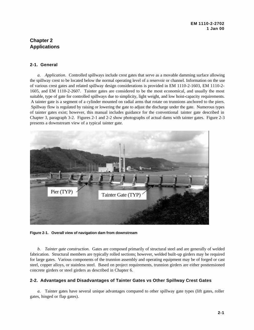
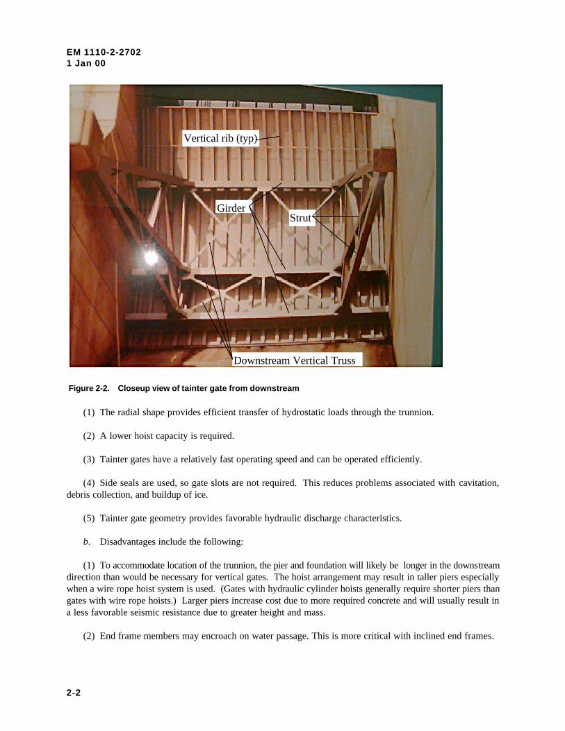
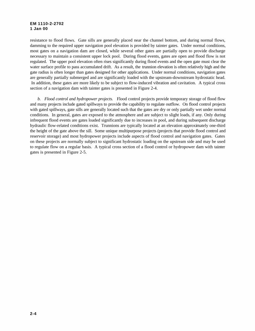
a. Application. Controlled spillways include crest gates that serve as a movable damming surface allowingthe spillway crest to be located below the normal operating level of a reservoir or channel. Information on the useof various crest gates and related spillway design considerations is provided in EM 1110-2-1603, EM 1110-2-1605, and EM 1110-2-2607. Tainter gates are considered to be the most economical, and usually the mostsuitable, type of gate for controlled spillways due to simplicity, light weight, and low hoist-capacity requirements. A tainter gate is a segment of a cylinder mounted on radial arms that rotate on trunnions anchored to the piers. Spillway flow is regulated by raising or lowering the gate to adjust the discharge under the gate. Numerous typesof tainter gates exist; however, this manual includes guidance for the conventional tainter gate described inChapter 3, paragraph 3-2. Figures 2-1 and 2-2 show photographs of actual dams with tainter gates. Figure 2-3presents a downstream view of a typical tainter gate.
Tainter Gate (TYP)Pier (TYP)
b. Tainter gate construction. Gates are composed primarily of structural steel and are generally of weldedfabrication. Structural members are typically rolled sections; however, welded built-up girders may be requiredfor large gates. Various components of the trunnion assembly and operating equipment may be of forged or caststeel, copper alloys, or stainless steel. Based on project requirements, trunnion girders are either posttensionedconcrete girders or steel girders as described in Chapter 6.
2-2. Advantages and Disadvantages of Tainter Gates vs Other Spillway Crest Gates
a. Tainter gates have several unique advantages compared to other spillway gate types (lift gates, rollergates, hinged or flap gates).
Figure 2-1. Overall view of navigation dam from downstream
EM 1110-2-27021 Jan 00
2-2
Vertical rib (typ)
GirderStrut
Downstream Vertical Truss
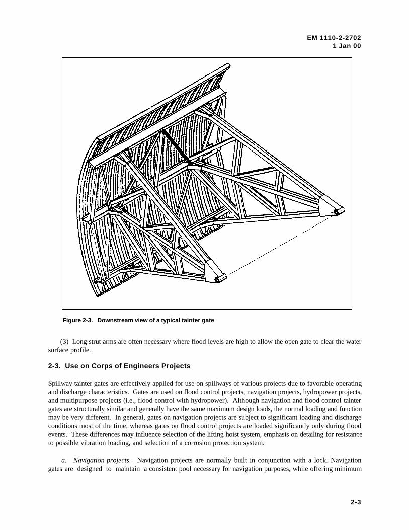
(1) The radial shape provides efficient transfer of hydrostatic loads through the trunnion.
(2) A lower hoist capacity is required.
(3) Tainter gates have a relatively fast operating speed and can be operated efficiently.
(4) Side seals are used, so gate slots are not required. This reduces problems associated with cavitation,debris collection, and buildup of ice.
(5) Tainter gate geometry provides favorable hydraulic discharge characteristics.
b. Disadvantages include the following:
(1) To accommodate location of the trunnion, the pier and foundation will likely be longer in the downstreamdirection than would be necessary for vertical gates. The hoist arrangement may result in taller piers especiallywhen a wire rope hoist system is used. (Gates with hydraulic cylinder hoists generally require shorter piers thangates with wire rope hoists.) Larger piers increase cost due to more required concrete and will usually result ina less favorable seismic resistance due to greater height and mass.
(2) End frame members may encroach on water passage. This is more critical with inclined end frames.
Figure 2-2. Closeup view of tainter gate from downstream
EM 1110-2-27021 Jan 00
2-3
(3) Long strut arms are often necessary where flood levels are high to allow the open gate to clear the watersurface profile.
2-3. Use on Corps of Engineers Projects
Spillway tainter gates are effectively applied for use on spillways of various projects due to favorable operatingand discharge characteristics. Gates are used on flood control projects, navigation projects, hydropower projects,and multipurpose projects (i.e., flood control with hydropower). Although navigation and flood control taintergates are structurally similar and generally have the same maximum design loads, the normal loading and functionmay be very different. In general, gates on navigation projects are subject to significant loading and dischargeconditions most of the time, whereas gates on flood control projects are loaded significantly only during floodevents. These differences may influence selection of the lifting hoist system, emphasis on detailing for resistanceto possible vibration loading, and selection of a corrosion protection system.
a. Navigation projects. Navigation projects are normally built in conjunction with a lock. Navigationgates are designed to maintain a consistent pool necessary for navigation purposes, while offering minimum
Figure 2-3. Downstream view of a typical tainter gate
EM 1110-2-27021 Jan 00
2-4
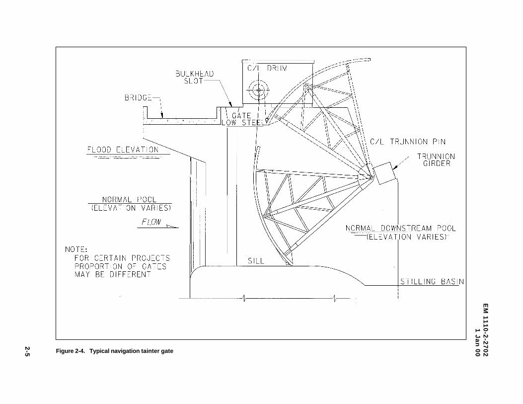
resistance to flood flows. Gate sills are generally placed near the channel bottom, and during normal flows,damming to the required upper navigation pool elevation is provided by tainter gates. Under normal conditions,most gates on a navigation dam are closed, while several other gates are partially open to provide dischargenecessary to maintain a consistent upper lock pool. During flood events, gates are open and flood flow is notregulated. The upper pool elevation often rises significantly during flood events and the open gate must clear thewater surface profile to pass accumulated drift. As a result, the trunnion elevation is often relatively high and thegate radius is often longer than gates designed for other applications. Under normal conditions, navigation gatesare generally partially submerged and are significantly loaded with the upstream-downstream hydrostatic head. In addition, these gates are more likely to be subject to flow-induced vibration and cavitation. A typical crosssection of a navigation dam with tainter gates is presented in Figure 2-4.
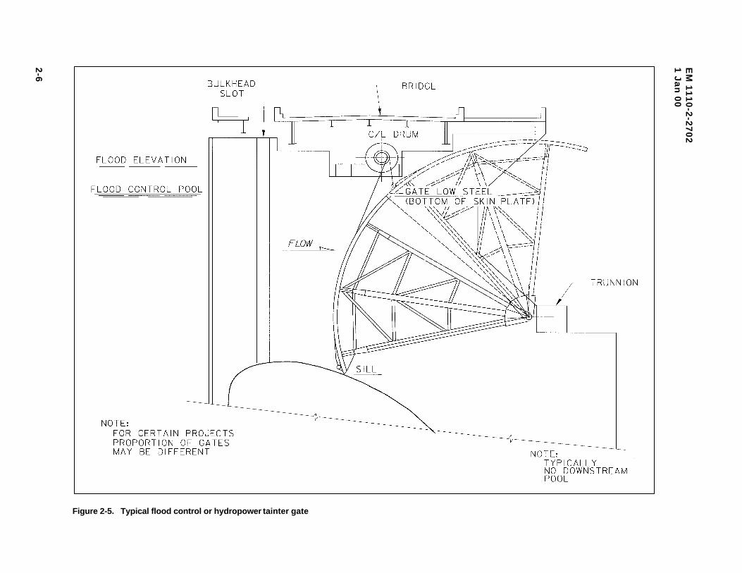
b. Flood control and hydropower projects. Flood control projects provide temporary storage of flood flowand many projects include gated spillways to provide the capability to regulate outflow. On flood control projectswith gated spillways, gate sills are generally located such that the gates are dry or only partially wet under normalconditions. In general, gates are exposed to the atmosphere and are subject to slight loads, if any. Only duringinfrequent flood events are gates loaded significantly due to increases in pool, and during subsequent dischargehydraulic flow-related conditions exist. Trunnions are typically located at an elevation approximately one-thirdthe height of the gate above the sill. Some unique multipurpose projects (projects that provide flood control andreservoir storage) and most hydropower projects include aspects of flood control and navigation gates. Gateson these projects are normally subject to significant hydrostatic loading on the upstream side and may be usedto regulate flow on a regular basis. A typical cross section of a flood control or hydropower dam with taintergates is presented in Figure 2-5.
EM
11
10
-2-2
70
21
Ja
n 0
0
2-5 Figure 2-4. Typical navigation tainter gate
EM
11
10
-2-2
70
21
Ja
n 0
0
2-6
Figure 2-5. Typical flood control or hydropower tainter gate
EM 1110-2-27021 Jan 00
3-1
Chapter 3Tainter Gate Design
3-1. Introduction
This chapter presents design guidance for the Corps of Engineers standard tainter gate described herein.The configuration for the standard gate has resulted from much practical and theoretical investigation ofalternatives and over 60 years of design and field experience with construction, operation, andmaintenance. It is generally the simplest and most economical tainter gate configuration for mostapplications.
3-2. Geometry, Components, and Sizing
a. Standard Corps of Engineers tainter gate geometry and components.
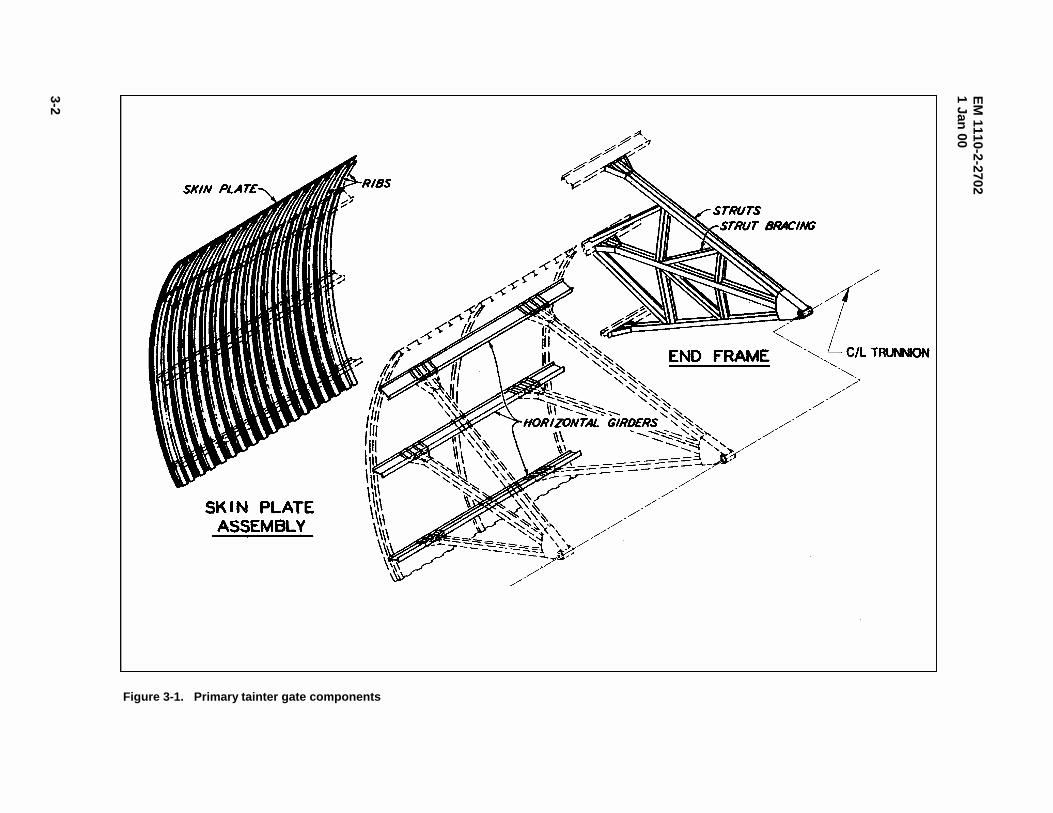
(1) Primary gate components. The principal elements of a conventional tainter gate are the skin plateassembly, horizontal girders, end frames, and trunnions (Figure 3-1). The skin plate assembly, whichforms a cylindrical damming surface, consists of a skin plate stiffened and supported by curved verticalribs. Structurally, the skin plate acts compositely with the ribs (usually structural Tee sections) to form theskin plate assembly. The skin plate assembly is supported by the horizontal girders that span the gatewidth. The downstream edge of each rib is attached to the upstream flange of the horizontal girders. Thehorizontal girders are supported by the end frames. End frames consist of radial struts or strut arms andbracing members that converge at the trunnion which is anchored to the pier through the trunnion girder. The end frames may be parallel to the face of the pier (support the horizontal girders at the ends) orinclined to the face of the pier (support the horizontal girders at some distance from the end with cantileverportions at each end). The trunnion is the hinge upon which the gate rotates. The trunnion is supported bythe trunnion girder which is addressed in Chapter 6.
(2) Other structural members. Structural bracing members are incorporated to resist specific loadsand/or to brace compression members. Certain bracing members are significant structural members, whileothers can be considered secondary members.
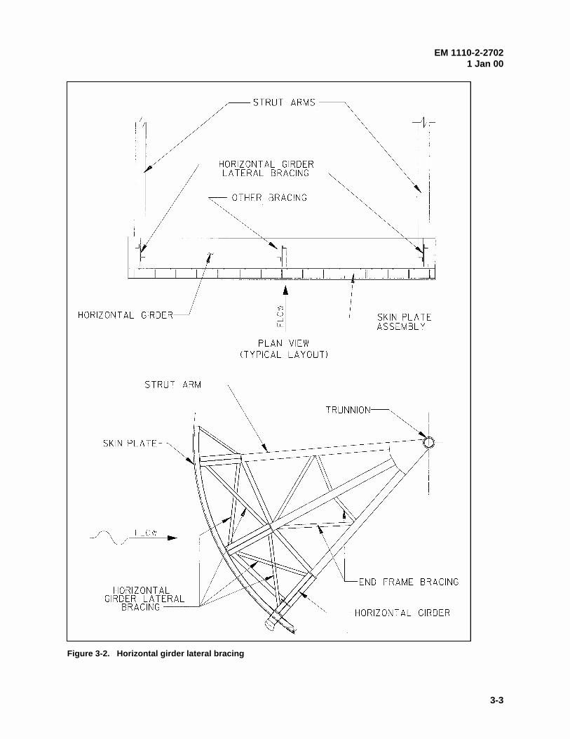
(a) Horizontal girder lateral bracing. Cross bracing is generally placed between adjacent girders in aplane perpendicular to the girder axes, sometimes at several locations along the length of the girders. Thishorizontal girder lateral bracing may simply provide lateral bracing for the girders or may serve to carryvertical forces from the skin plate assembly to the end frame. Lateral bracing that is located in the sameplane with the end frames is generally made up of significant structural members, while intermediatebracing located away from the end frames provides girder lateral stability and can be considered secondarymembers. The bracing located in the same plane with the end frames carries significant vertical forcesfrom the skin plate assembly to the end frame and is often considered a part of the end frame (Figure 3-2).
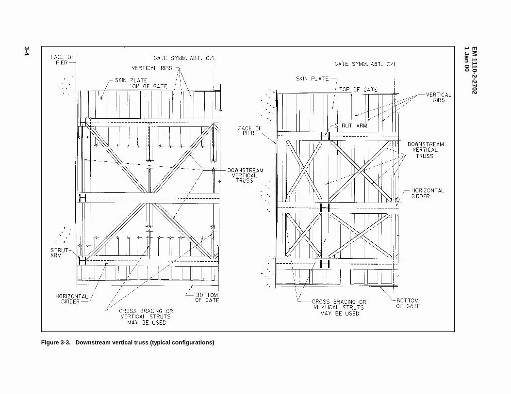
(b) Downstream vertical truss. The downstream vertical truss consists of bracing provided betweenthe downstream flanges of the horizontal girders. Various configurations have been used depending on thegate size and configuration as shown by Figure 3-3. For gates with more than two girders, the downstreamvertical truss does not lie in a single plane. Since the horizontal girders are arranged along the arc of theskin plate assembly, the downstream girder flanges do not lie in the same plane. Therefore,
EM
1110-2-27021 Jan
00
3-2
Figure 3-1. Primary tainter gate components
EM 1110-2-27021 Jan 00
3-3
Figure 3-2. Horizontal girder lateral bracing
EM
1110-2-27021 Jan
00
3-4
Figure 3-3. Downstream vertical truss (typical configurations)
EM 1110-2-27021 Jan 00
3-5
bracing members located between one pair of adjacent horizontal girders are not in the same plane as thosebetween the next pair. This out-of-plane geometry is commonly ignored for design purposes.
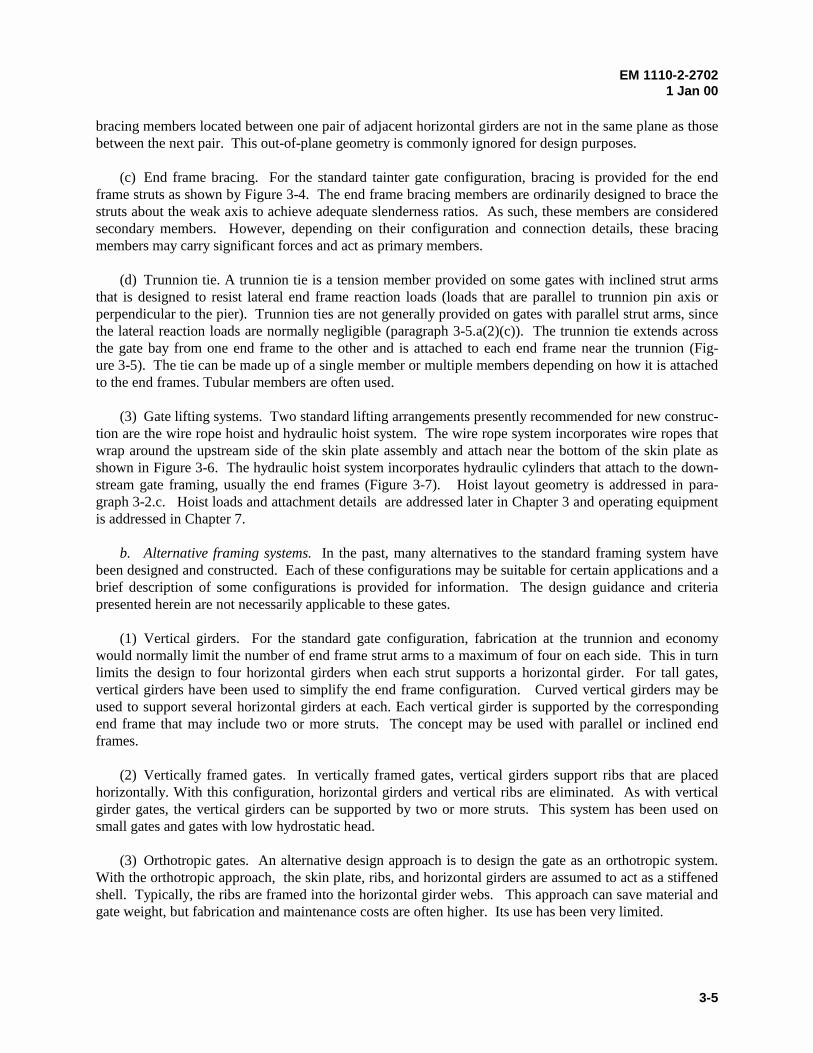
(c) End frame bracing. For the standard tainter gate configuration, bracing is provided for the endframe struts as shown by Figure 3-4. The end frame bracing members are ordinarily designed to brace thestruts about the weak axis to achieve adequate slenderness ratios. As such, these members are consideredsecondary members. However, depending on their configuration and connection details, these bracingmembers may carry significant forces and act as primary members.
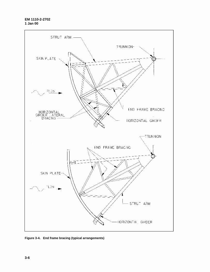
(d) Trunnion tie. A trunnion tie is a tension member provided on some gates with inclined strut armsthat is designed to resist lateral end frame reaction loads (loads that are parallel to trunnion pin axis orperpendicular to the pier). Trunnion ties are not generally provided on gates with parallel strut arms, sincethe lateral reaction loads are normally negligible (paragraph 3-5.a(2)(c)). The trunnion tie extends acrossthe gate bay from one end frame to the other and is attached to each end frame near the trunnion (Fig-ure 3-5). The tie can be made up of a single member or multiple members depending on how it is attachedto the end frames. Tubular members are often used.
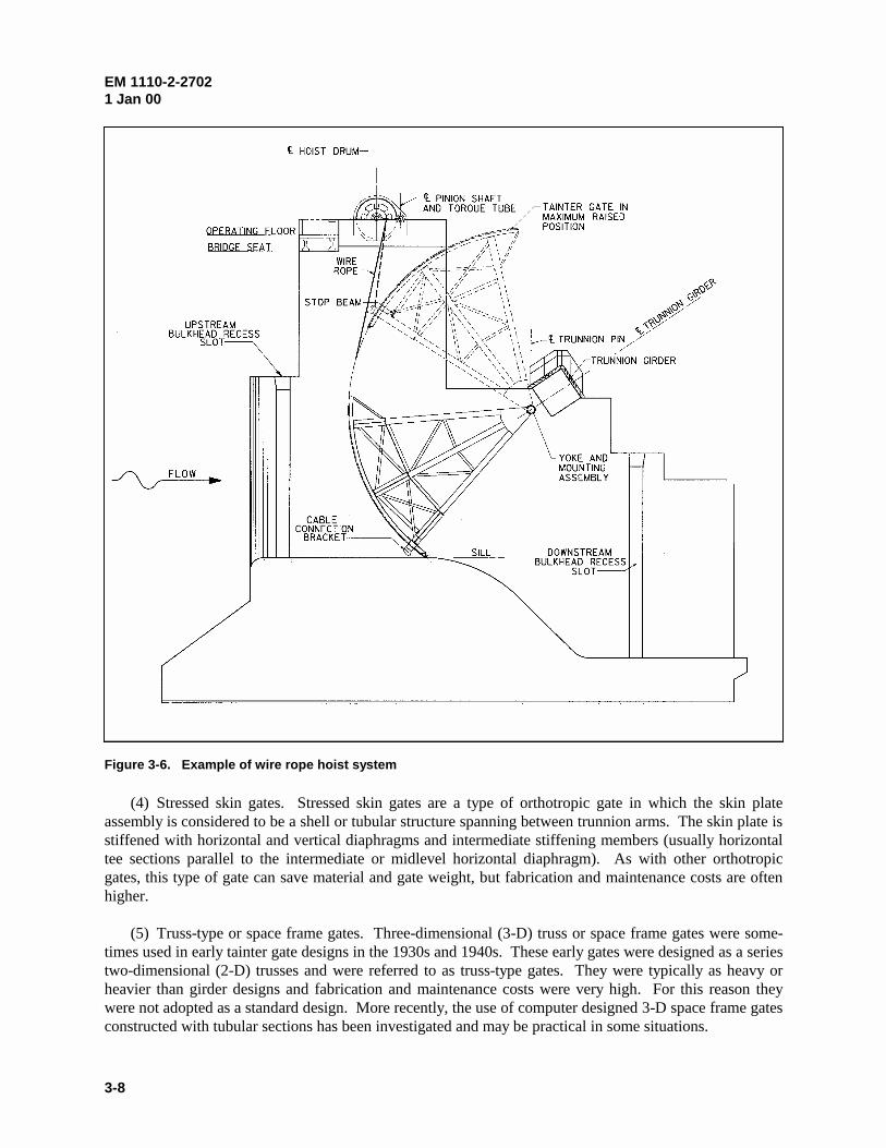
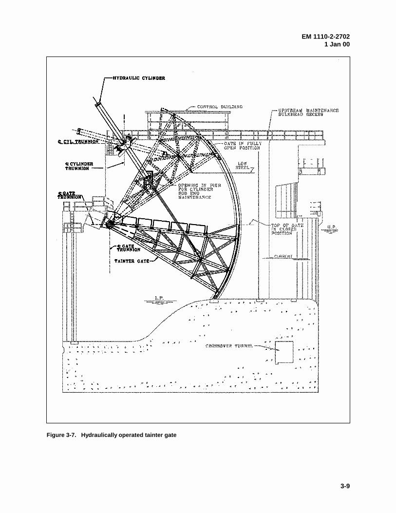
(3) Gate lifting systems. Two standard lifting arrangements presently recommended for new construc-tion are the wire rope hoist and hydraulic hoist system. The wire rope system incorporates wire ropes thatwrap around the upstream side of the skin plate assembly and attach near the bottom of the skin plate asshown in Figure 3-6. The hydraulic hoist system incorporates hydraulic cylinders that attach to the down-stream gate framing, usually the end frames (Figure 3-7). Hoist layout geometry is addressed in para-graph 3-2.c. Hoist loads and attachment details are addressed later in Chapter 3 and operating equipmentis addressed in Chapter 7.
b. Alternative framing systems. In the past, many alternatives to the standard framing system havebeen designed and constructed. Each of these configurations may be suitable for certain applications and abrief description of some configurations is provided for information. The design guidance and criteriapresented herein are not necessarily applicable to these gates.
(1) Vertical girders. For the standard gate configuration, fabrication at the trunnion and economywould normally limit the number of end frame strut arms to a maximum of four on each side. This in turnlimits the design to four horizontal girders when each strut supports a horizontal girder. For tall gates,vertical girders have been used to simplify the end frame configuration. Curved vertical girders may beused to support several horizontal girders at each. Each vertical girder is supported by the correspondingend frame that may include two or more struts. The concept may be used with parallel or inclined endframes.
(2) Vertically framed gates. In vertically framed gates, vertical girders support ribs that are placedhorizontally. With this configuration, horizontal girders and vertical ribs are eliminated. As with verticalgirder gates, the vertical girders can be supported by two or more struts. This system has been used onsmall gates and gates with low hydrostatic head.
(3) Orthotropic gates. An alternative design approach is to design the gate as an orthotropic system.With the orthotropic approach, the skin plate, ribs, and horizontal girders are assumed to act as a stiffenedshell. Typically, the ribs are framed into the horizontal girder webs. This approach can save material andgate weight, but fabrication and maintenance costs are often higher. Its use has been very limited.
EM 1110-2-27021 Jan 00
3-6
Figure 3-4. End frame bracing (typical arrangements)
EM 1110-2-27021 Jan 00
3-7
Figure 3-5. Trunnion tie
EM 1110-2-27021 Jan 00
3-8
(4) Stressed skin gates. Stressed skin gates are a type of orthotropic gate in which the skin plateassembly is considered to be a shell or tubular structure spanning between trunnion arms. The skin plate isstiffened with horizontal and vertical diaphragms and intermediate stiffening members (usually horizontaltee sections parallel to the intermediate or midlevel horizontal diaphragm). As with other orthotropicgates, this type of gate can save material and gate weight, but fabrication and maintenance costs are oftenhigher. (5) Truss-type or space frame gates. Three-dimensional (3-D) truss or space frame gates were some-times used in early tainter gate designs in the 1930s and 1940s. These early gates were designed as a seriestwo-dimensional (2-D) trusses and were referred to as truss-type gates. They were typically as heavy orheavier than girder designs and fabrication and maintenance costs were very high. For this reason theywere not adopted as a standard design. More recently, the use of computer designed 3-D space frame gatesconstructed with tubular sections has been investigated and may be practical in some situations.
Figure 3-6. Example of wire rope hoist system
EM 1110-2-27021 Jan 00
3-9
Figure 3-7. Hydraulically operated tainter gate
EM 1110-2-27021 Jan 00
3-10
(6) Overflow/submersible gates. These gates may be of the standard configuration but are designedto allow water to pass over the top the gate. Deflector plates are often provided on the downstream side ofthe gate to allow water and debris to pass over the framing with minimized impact. Other gates have beendesigned to include a downstream skin plate, so the gate is completely enclosed. Vibration problems havebeen prevalent with this type gate.
c. General gate sizing and layout considerations. The sizing of the gates is an important early stepin the design process. Gate size affects other project components, project cost, operation, and maintenanceof the project. The following paragraph includes various considerations that should be taken into accountwhile selecting a practical and economical tainter gate size. Related guidance can be found in EMs 1110-2-1603, 1110-2-1605, and 1110-2-2607. Appendix D provides pertinent data for a number of existingtainter gates. Each project is unique and the gate size and configuration should be determined based oncareful study of the project as a whole. The best alternative is not necessarily a gate with the lightest gateweight-to-size ratio.
(1) Gate size. The hydraulic engineer will normally establish the limiting parameters for gate heightand width. Within those limits, various height-to-width ratios should be studied to find the most suitablegate size for the project. The structural designer should coordinate closely with the hydraulic engineer indetermining the basic limiting requirements for size and shape. The size, shape, and framing system of thegates should be selected to minimize the overall cost of the spillway, rather than the gate itself. Determination of gate size will also consider practical operation and maintenance considerations specific tothe project.
(2) Gate width. The gate width will be determined based on such factors as maximum desirable widthof monoliths, length of spillway, bridge spans, drift loading, overall monolith stability, and loads ontrunnions and anchorages. On navigation projects, the gates may be set equal to the width of the lock, sothat one set of bulkheads can serve both structures. It is usually desirable to use high gates rather than lowgates for a given discharge, since the overall spillway width is reduced and results in a more economicalspillway.
(3) Gate radius. The skin plate radius will normally be set equal to or greater than the height of thegate. The radius of the gate will also be affected by operational requirements concerning clearancebetween the bottom of the gate and the water surface profile. This is often the case for navigation dams onrivers where the gate must clear the flood stage water surface profile to pass accumulated drift. On suchprojects requiring larger vertical openings, it is common to use a larger radius, up to four times the gateheight, to allow for a greater range of opening. This will require longer piers for satisfactory location ofthe trunnion girder.
(4) Trunnion location. It is generally desirable to locate the trunnion above the maximum flood watersurface profile to avoid contact with floating ice and debris and to avoid submergence of the operatingparts. However, it is sometimes practical to allow submergence for flood events, especially on navigationdams. Designs allowing submergence of 5 to 10 percent of the time are common. Gates incorporating atrunnion tie should not experience trunnion submergence. If other considerations do not control, it willusually be advantageous to locate the trunnion so that the maximum reaction is approximately horizontal tothe trunnion girder (typically about one-third the height of the gate above the sill for hydrostatic loading).This will allow for simplified design and construction by allowing the trunnion posttensioned anchorage tobe placed in horizontal layers.
EM 1110-2-27021 Jan 00
3-11
(5) Operating equipment location. The type and position of the gate lifting equipment can have asignificant effect on gate forces as the gate is moved through its range of motion. As stated previously, thetwo gate lifting systems recommended for new construction are the wire rope hoist system and the hydraulic hoist system.
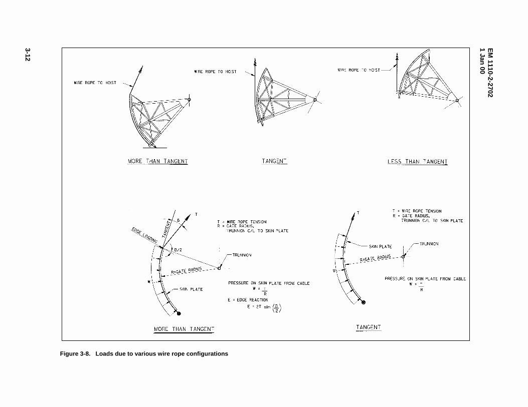
(a) Wire rope hoist system. Generally, the most suitable layout for wire rope is one that minimizes theeffects of lifting forces on the gate and lifting equipment. The three possible variations in cable layoutinclude: 1) cable more than tangent to the skin plate, 2) cable tangent to the skin plate, and 3) cable lessthan tangent to the skin plate (Figure 3-8). Considering the gate and hoist system, the most idealconfiguration is when the rope is pulled vertically and is tangent to the arc of the skin plate. For thiscondition, horizontal forces exerted to the hoist equipment are insignificant, and rope contact forces actradially on the gate. A nonvertical wire rope introduces a horizontal component of force that must bebalanced by the operating equipment and associated connections. With a rope in the more-than-tangentcondition, an edge reaction force exists at the top of the skin plate due to an abrupt change in ropecurvature. This force affects the rope tension, trunnion reaction, and rib design forces. If the rope is in theless-than-tangent configuration, the rope force required to lift the gate increases exponentially as thedirection of rope becomes further from tangent. The large lifting force affects the hoist and gate. Due tovarious constraints, some compromise on location of the hoist is usually required. Many gates have non-vertical wire ropes and many gates include ropes that are nontangent at or near the full, closed and/or full,opened positions.
(b) Hydraulic cylinder hoist system. Many new gate designs utilize hydraulic cylinder hoist systemsbecause they are usually cost effective. However, these systems have some disadvantages and are notsuited for all applications. Close coordination with the mechanical design engineer is required to optimizethe hoist system. A hydraulic cylinder hoist system generally comprises two cylinders, one located at eachside of the gate. Each cylinder pivots on a trunnion mounted on the adjacent pier, and the piston rod isattached to the gate. The cylinder magnitude of force and its orientation will change continuallythroughout the range of motion. In determining the optimum cylinder position, the location of the cylindertrunnion and piston rod connection to the gate are interdependent. Generally, the piston rod connectionposition is selected and then the cylinder trunnion position is determined to minimize effects of liftingforces. For preliminary design layouts, it is often assumed that the cylinder will be at a 45-deg angle fromhorizontal when the gate is closed, although optimization studies may result in a slightly differentorientation. Generally, the most suitable location for the piston rod connection is on the gate end frame ator near the intersection of a bracing member and strut. It is preferable to have the piston rod connectionabove tailwater elevations that are consistent with the gate operating versus tailwater stage schedule;however, partial submergence may be acceptable for navigation projects. The connection locationinfluences the gate trunnion reaction forces due to simple static equilibrium. When the connection islocated upstream of the gate center of gravity, the dead load reaction at the gate trunnion will be downwardwhile the gate is lifted off the sill. However, if the connection is downstream of the center of gravity, thereaction at the gate trunnion will act upward while the gate is lifted off the sill.
(6) Other sizing considerations. The face of gate and the stop log slots should be located far enoughapart to permit the installation of maintenance scaffolding. Spillway bridge clearance is a factor indetermining the gate radius and the trunnion location. Operating clearances from the bridge and thelocation of the hoist will usually require that the sill be placed somewhat downstream from the crest, butthis distance should be as small as possible to economize on height of gate and size of pier. Additionalconsiderations could include standardization of gate sizes on a project involving multiple spillways. Thestandardization of sizes could result in savings by eliminating multiple sets of bulkheads, standardizingmachinery, and reducing stored replacement parts, etc.
EM
1110-2-27021 Jan
00
3-12
Figure 3-8. Loads due to various wire rope configurations
EM 1110-2-27021 Jan 00
3-13
3-3. Material Selection
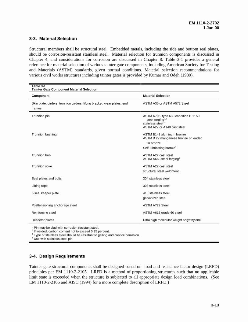
Structural members shall be structural steel. Embedded metals, including the side and bottom seal plates,should be corrosion-resistant stainless steel. Material selection for trunnion components is discussed inChapter 4, and considerations for corrosion are discussed in Chapter 8. Table 3-1 provides a generalreference for material selection of various tainter gate components, including American Society for Testingand Materials (ASTM) standards, given normal conditions. Material selection recommendations forvarious civil works structures including tainter gates is provided by Kumar and Odeh (1989).
Table 3-1Tainter Gate Component Material Selection
Component Material Selection
Skin plate, girders, trunnion girders, lifting bracket, wear plates, end
frames
ASTM A36 or ASTM A572 Steel
Trunnion pin ASTM A705, type 630 condition H 1150 steel forging1,2
stainless steel3
ASTM A27 or A148 cast steel
Trunnion bushing ASTM B148 aluminum bronzeASTM B 22 manganese bronze or leaded
tin bronze
Self-lubricating bronze4
Trunnion hub ASTM A27 cast steelASTM A668 steel forging2
Trunnion yoke ASTM A27 cast steel
structural steel weldment
Seal plates and bolts 304 stainless steel
Lifting rope 308 stainless steel
J-seal keeper plate 410 stainless steel
galvanized steel
Posttensioning anchorage steel ASTM A772 Steel
Reinforcing steel ASTM A615 grade 60 steel
Deflector plates Ultra high molecular weight polyethylene
1 Pin may be clad with corrosion resistant steel.2 If welded, carbon content not to exceed 0.35 percent.3 Type of stainless steel should be resistant to galling and crevice corrosion.4 Use with stainless steel pin.
3-4. Design Requirements
Tainter gate structural components shall be designed based on load and resistance factor design (LRFD)principles per EM 1110-2-2105. LRFD is a method of proportioning structures such that no applicablelimit state is exceeded when the structure is subjected to all appropriate design load combinations. (SeeEM 1110-2-2105 and AISC (1994) for a more complete description of LRFD.)
EM 1110-2-27021 Jan 00
3-14
a. Design basis. The basic safety check in LRFD may be expressed mathematically as
where
Ji = load factors that account for variability in the corresponding loads
Qni = nominal load effects defined herein
D = reliability factor as defined in EM 1110-2-2105
I = resistance factor that reflects the uncertainty in the resistance for the particular limit state and, in a relative sense, the consequence of attaining the limit state.
Rn = nominal resistance.
For the appropriate limit states (paragraph 3-4.c), all structural components shall be sized such that thedesign strength DIRn is at least equal to the required strength 6JiQni. The design strength shall bedetermined as specified in paragraph 3-4.c. The required strength must be determined by structuralanalysis for the appropriate load combinations specified in paragraph 3-4.b.
b. Load requirements.
(1) Loads. Loads that are applicable to tainter gate design include gravity loads, hydrostatic loads,operating loads, ice and debris loads, and earthquake loads. Reactions are not listed below or in the loadcases. Reactions loads are not factored since they are determined from equilibrium with factored loadsapplied. As a result, reaction forces reflect the load factors of the applied loads.
(a) Gravity loads. Gravity loads include dead load or weight of the gate (D), mud weight (M), and iceweight (C), and shall be determined based on site-specific conditions.
(b) Hydrostatic loads. Hydrostatic loads consist of hydrostatic pressure on the gate considering bothupper and lower pools. Three levels of hydrostatic loads are considered. The maximum hydrostatic loadH1 is defined as the maximum net hydrostatic load that will ever occur. The design hydrostatic load H2 isthe maximum net hydrostatic load considering any flood up to a 10-year event. The normal hydrostaticload H3 is the temporal average net load from upper and lower pools, i.e., the load that exists from poollevels that are exceeded up to 50 percent of the time during the year.
(c) Gate lifting system (operating machinery) loads. Operating machinery is provided to support gatesduring lifting or lowering operations. Under normal operating conditions, the machinery provides forcesnecessary to support the gate, and for the load cases described herein, these forces are treated as reactionforces. Loads Q are machinery loads for conditions where the machinery exerts applied forces on anotherwise supported gate (paragraph 3-4.b(2)(f)). There are three levels of loads applied by the operatingmachinery to the gate. The hydraulic cylinder maximum downward load Q1 is the maximum compressivedownward load that a hydraulic hoist system can exert if the gate gets jammed while closing or when thegate comes to rest on the sill. The hydraulic cylinder at-rest load Q2 is the downward load that a hydraulic
R Q nnii DIdJ6 (3-1)
EM 1110-2-27021 Jan 00
3-15
cylinder exerts while the gate is at rest on the sill (due to cylinder pressure and the weight of the piston androd). Loads Q1 and Q2 do not exist for wire rope hoist systems. The maximum upward operatingmachinery load Q3 is the maximum upward load that can be applied by the wire rope or hydraulic hoistsystems when a gate is jammed or fully opened. The gate lifting systems exert forces on specific gatemembers whether the forces are reactions or applied loads. For example, where the wire rope bears on theskin plate, the rope exerts a contact pressure (line load) on the skin plate. The contact pressure force isequal to the rope tension force divided by the gate radius. If the wire rope is not tangent to the skin plate,the rope will exert an additional concentrated load on the gate (Figure 3-8.). Concentrated forces thattypically vary with gate position in magnitude and direction are present at the attachment points for bothgate lifting systems. Operating machinery loads must be quantified in consultation with the mechanicalengineer that designs the machinery. Determination of load magnitudes and suggested coordination arediscussed in Chapter 7.
(d) Ice-impact load I. The ice-impact load is specified to account for impact of debris (timber, ice, andother foreign objects) or lateral loading due to thermal expansion of ice sheets. Additionally, this loadprovides the overall structure with a margin of safety against collapse under barge impact. (Barge impactis an accidental event that is not practical to design for and is not specifically considered in design). I isspecified as a uniform distributed load of 73.0 KN/M (5.0 kips/ft) that acts in the downstream directionand is applied along the width of the gate at the upper pool elevation.
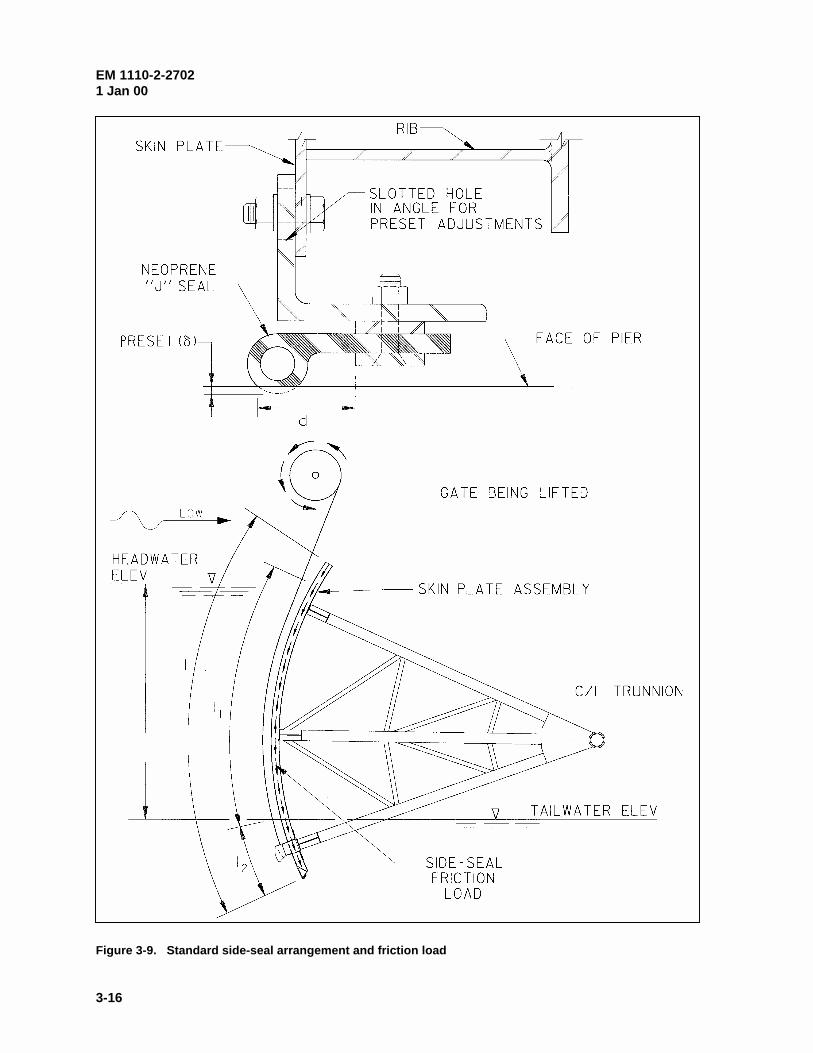
(e) Side-seal friction load Fs. Loads exist along the radius of the skin plate because of frictionbetween the side seals and the side-seal plate when the gate is opening or closing. The friction force perunit length along the skin plate edge dFs/dl is equal to the product of the coefficient of friction and normalforce between the seal plates and the side seals. For rubber seals, a coefficient of friction (Ps) equal to 0.5is recommended. (Seals that have Teflon rubbing surfaces provide a lower coefficient of friction and arerecommended for serviceability. However, wear of the Teflon is a concern, and applying a lowercoefficient of friction for design purposes is not recommended.) The normal force on the side seal is afunction of the preset force in the seal and the hydrostatic pressure on the surface of the seal. For normaltainter gate configurations, side-seal friction can be approximated by Equation 3-2 (Figure 3-9).
��
���
� l h + 2
h l
2
d + l S=F 21wsss ��� (3-2)
where
Ps = coefficient of side-seal friction
l = total length of the side seal
l1 = length of the side seal from the headwater to the tailwater elevations or bottom of the seal if there is no tailwater on the gate
l2 = length of the side seal from the tailwater elevation to the bottom of the seal (equals zero if there is no tailwater on the gate)
S = force per unit length induced by presetting the seal and can be approximated as
EM 1110-2-27021 Jan 00
3-16
Figure 3-9. Standard side-seal arrangement and friction load
EM 1110-2-27021 Jan 00
3-17
S = 3 EI
d 3
�, where G is the seal preset distance
Jw = unit weight of water
d = width of the J seal exposed to upper pool hydrostatic pressure (Figure 3-9)
h = vertical distance taken from the headwater surface to the tail water surface or the bottom of the seal if there is no tailwater on the gate (Figure 3-9)
(f) Trunnion pin friction loads Ft. During opening or closing of gates, friction loads exist around thesurface of the trunnion pin between the bushing and the pin and at the end of the hub between the hubbushing and side plate (yoke plate for yoke mounted pins) (Refer to Chapter 4 for description of trunnioncomponents.). These friction loads result in a trunnion friction moment Ft about the pin that must beconsidered in design. The friction moment around the pin is a function of a coefficient of friction, thetrunnion reaction force component R that acts normal to the surface of the pin (parallel to the pier face),and the radius of the pin. The friction moment at the end of the hub is a function of a coefficient offriction, the trunnion reaction force component Rz that acts normal to the end of the pin (normal to the pierface), and the average radius of the hub. The reaction forces R and Rz are discussed in para-graphs 3-5.a(2)(c) and 3-5.a(3). A coefficient of friction of 0.3 is an upper bound for design purposes.This is a conservative value that applies for any bushing material that may be slightly worn or improperlymaintained. A realistic coefficient of friction for systems with lubricated bronze or aluminum bronzebushings is 0.1 to 0.15. The designer should ensure that detailed criteria are specified in project operationsand maintenance manuals to ensure that trunnion systems are properly maintained.
(g) Earthquake design loads E. Earthquake design loads are specified based on an operational basisearthquake (OBE) with a 144-year mean recurrence interval. For gate design, the direction of earthquakeacceleration is assumed to be parallel to the gate bay centerline (i.e., it is assumed that the effects ofvertical acceleration and acceleration perpendicular to the gate bay are comparatively negligible).Earthquake forces include mass inertia forces and hydrodynamic forces of water on the structure. When atainter gate is submerged, the inertial forces due to structural weight, ice, and mud are insignificant whencompared with the hydrodynamic loads and can be ignored. For load case 1 (paragraph 3-4.b(2)(a)), thestructure is submerged, and E shall be based on inertial hydrodynamic effects of water moving with thestructure. For the structural member in question, E is determined based on the pressure that acts over thetributary area of the particular member. The hydrodynamic pressure may be estimated by Equation 3-3(Westergaard 1931). This equation applies for water on the upstream and downstream sides of thestructure.
Hy a 8
7 = p cwJ (3-3)
where
p = lateral hydrodynamic pressure at a distance y below the pool surface
Jw = unit weight of water
EM 1110-2-27021 Jan 00
3-18
H = reservoir pool depth (to bottom of dam) on upstream or downstream side of the structure
ac = maximum base acceleration of the dam due to the OBE (expressed as a fraction of gravitational acceleration)
For load case 5 (paragraph 3-4.b(2)(e)), water is not on the structure, and E is due to mass inertia forces ofthe structure, ice, and mud.
Wa = E MC,D,c (3-4)
where
WD,C,M = weight of the portion of the structure, ice, and mud that are supported by the member in question.
(h) Wave load WA. Wave loads are site specific and should be determined in consultation with theproject hydraulic engineer. Guidance on development of wave loading is provided in the Shore ProtectionManual (1984).
(i) Wind load W. Wind loads are site specific and should be calculated in accordance with ASCE(1995) but not more than 2.4 KPa (50 psf). Wind loads are small when compared to hydrostatic loads andonly affect gate reactions when the gate is in an open position.
(2) Load cases. Tainter gates shall be designed considering the strength requirements for each of thefollowing load cases and corresponding load combinations. The most unfavorable effect on various gatecomponents may occur when one or more of the loads in a particular load combination is equal to zero.Various conditions are described for the cases of gate in the closed position (load case 1), gate operating(load case 2 and load case 3), gate jammed (load case 4), and gate fully opened (load case 5). Theoperating machinery may include forces in each load case; however, these forces are treated as gate reac-tions in some cases. As a result, the load Q does not appear in some load cases (paragraph 3-4.b(2)(f)).
(a) Load case 1: Gate closed. Load combinations for this load case (Equations 3-5, 3-6, and 3-7)apply when the gate is in the closed position.
1.4 H + 1.2D + 1.6(C + M) + 1.2 Q1 2 (3-5)
]I)kQ.( or )1.2WQ.( or Q1.2[ + M)+1.6(C + 1.2D + H1.4 IA12 �� 22 2121 (3-6)
1.2 H + 1.2D + 1.6(C+ M) + 1.0E3 (3-7)
1) Extreme pool condition. Equation 3-5 describes the condition where the maximum hydrostaticload H1 is applied, gravity loads D, C, and M exist, and the hydraulic cylinders exert the at-rest load Q2.(For gates with wire rope hoists, Q2 does not exist.) It is assumed that the likelihood of the simultaneousoccurrence of H1 and WA or I or E is negligible.
2) Operating pool condition. Equation 3-6 describes the condition for which the moderate hydro-static load H2 acts in combination with Q1 or WA or I. Gravity loads D, C, and M always exist, and it isassumed that Q1, WA, and I will not occur at the same time. The load Q2 will likely always exist with W or
EM 1110-2-27021 Jan 00
3-19
I. The I load factor kI shall be equal to 1.6 when considering ice load due to thermal expansion and 1.0when considering impact of debris.
3) Earthquake condition. Equation 3-7 describes the condition where the normal hydrostatic load H3
acts in combination with earthquake loading E and gravity loads D, C, and M exist.
(b) Load case 2: Gate operating with two hoists. Load combinations for this load case (Equations 3-8and 3-9) represent the condition when the gate is opening or closing with both hoists functional. Operatingmachinery loads Q are not listed in these load combinations, because it is assumed that the hoists are gatesupports that will include reaction forces (paragraph 3-4.b(2)(f)). This load case does not include Ebecause it is assumed that the likelihood of opening or closing the gate at the same time an earthquakeoccurs is negligible. Effects on members forces should be checked considering the entire operating range(any position between the sill and the upper gate stops) for gates either opening or closing.
1.4 H + 1.2D + 1.6(C+ M) + 1.4 F + 1.0 F1 S t (3-8)
1.4 H + 1.2D + 1.6(C+ M) + 1.4 F + 1.0 F + (1.2W or k I)2 S t A I (3-9)
1) Extreme pool condition. Equation 3-8 (similar to Equation 3-5) describes the condition where themaximum hydrostatic load H1 is applied, gravity loads D, C, and M exist, and friction loads Fs and Ft existdue to gate motion. It is assumed that the likelihood of the simultaneous occurrence of H1 and WA or I or Eis negligible.
2) Operating pool condition. Equation 3-9 (similar to Equation 3-6) describes the condition forwhich the moderate hydrostatic load H2 acts in combination with WA or I. Gravity loads D, C, and M exist,and due to gate motion, friction loads Fs and Ft are applied. In the determination of H2, the lower poolelevation will include a hydrodynamic reduction due to flow of water under the gate. The magnitude ofhydrodynamic reduction should be determined in consultation with the project hydraulic engineer. Asdescribed for Equation 3-6, kI shall be equal to 1.6 for ice and 1.0 for debris.
(c) Load case 3: Gate operating with one hoist. The load combination described by Equation 3-10applies for the case where the gate is operated with only one hoist (subsequent to failure of the other hoist). Effects on members forces should be checked for all gate positions throughout the operating range for thegate either opening or closing.
1.4 H + 1.2D + 1.6(C+ M) + 1.4 F + 1.0 F2 S t (3-10)
For this case, the moderate hydrostatic load H2 is applied, gravity loads D, C, and M exist, and frictionloads Fs and Ft exist due to gate motion. In the determination of H2, the lower pool elevation will include ahydrodynamic reduction due to flow of water under the gate (must be coordinated with the projecthydraulic engineer). The effects of H1, WA, I, or E are not considered for this load case, since it isassumed that the likelihood of the simultaneous occurrence one of these loads and the failure of one hoistis negligible. Design considerations for this condition are provided in paragraph 3-5.e and serviceabilityconsiderations are discussed in paragraph 3-6.b(1).
(d) Load case 4: Gate jammed. The load combination of Equation 3-11 accounts for the possiblecondition where one hoist fails, and the gate becomes jammed between piers due to twist of the gate (suchthat one end frame is higher than the other). Effects on members forces should be checked with the gatejammed at positions throughout the operating range.
EM 1110-2-27021 Jan 00
3-20
)Q1.2or Q(1.2 + M)+1.6(C + 1.2D + H1.4 132 (3-11)
For this case, the moderate hydrostatic load H2 is applied in combination with the maximum machineryload Q3 (for wire rope hoists or hydraulic hoists) or Q1 (for hydraulic hoists), and gravity loads D, C, andM exist. It is assumed that only one hoist is functional. In the determination of H2, the lower poolelevation will include a hydrodynamic reduction due to flow of water under the gate (must be coordinatedwith the project hydraulic engineer). The effects of H1, WA, I, or E are not considered for this load case,since it is assumed that the likelihood of the simultaneous occurrence one of these loads while the gate isjammed is negligible.
(e) Load case 5: Gate fully opened. The load combination of Equation 3-12 accounts for the condi-tion where the gate is fully opened (raised to the gate stops) with wind, earthquake, or operating equipmentloads.
D 3k D + 1.6(C + M) + (1.3W or 1.0E or 1.2 Q ) (3-12)
For this case, it is assumed that the gate is raised above the pool, so effects of H, WA, and I are notincluded. Effects of Q3 oppose gravity load effects, and effects of W or E may add to or oppose gravityload effects. When Q3 is considered, or when effects W or E oppose those of gravity, C and M should beequal to 0 and the load factor kD is equal to 0.9. When the direction of W or E is such that their effectincreases gravity load effects, kD is equal to 1.2 and C and M should be considered.
(f) Assumptions on support or loading of gate lifting systems (operating machinery). The loadcombinations included herein were developed for gate design based on various assumptions on loading andsupport conditions. (See Chapter 7 for discussion on criteria regarding load and operational requirementsfor operating machinery.) These assumptions must be considered in structural analysis of gate components(paragraph 3-5). For a tainter gate to be stable, rotational restraint must be provided by a suitable support. It is assumed that this support is the sill when the gate is closed (case 1), the hoists when the gate isoperated (case 2 and case 3), the pier or some obstruction at the gate sides when the gate is jammed(case 4), and the hoists or the gate stops when the gate is fully opened (case 5). In load cases 2, 3, andsome applications of 5, operating machinery loads Q are not included, since for these cases, the hoists aresupports. The hoists provide reaction forces which are a function of all other gate loads. In load cases 1,4, and some applications of 5, where the gate is supported by something other than the hoists, any forceexerted by the hoists is an external load on the gate Q.
c. Limit states and design strength for individual members. EM 1110-2-2105 requires that strengthand serviceability limit states be considered in the design of tainter gate structural components. Strengthlimit states include general yielding, instability, fatigue, and fracture. The design strength for eachapplicable limit state DIRn is calculated as the nominal strength Rn, multiplied by a resistance factor I anda reliability factor D. Except as modified herein, limit states, nominal strength Rn, and resistance factors Ishall be in accordance with AISC (1994). For normal conditions, D shall be equal to 0.9. For gates thatare normally submerged and whose removal would disrupt the entire project, or for gates in brackish wateror sea water, D shall be equal to 0.85. Fatigue and fracture design requirements are included in para-graph 3-8 and EM 1110-2-2105. Serviceability requirements for tainter gates are specified in para-graph 3-6. The following paragraphs provide specific guidance for the design of skin plate, ribs, girders,and end frame members.
(1) Skin plate. The skin plate shall be sized such that the maximum calculated stress is less than theyield limit state of DIbFy. In determining the required strength, all load cases in paragraph 3-4.b shall be
EM 1110-2-27021 Jan 00
3-21
considered; however, the ice-impact load I may be set equal to zero at the designer’s option. This isfrequently done, with the intent of allowing local damage to the skin plate for very infrequent loadingevents rather than increasing the gate weight.
(2) Rib members. Ribs shall be sized such that the maximum calculated moment Mu is less than thenominal bending strength of DIbMn. In determining the required strength Mu, all load cases in para-graph 3-4.b shall be considered. For load cases 2, 3, and 4, the maximum effect will normally occurassuming that the gate is near the closed position.
(3) Girders. Girders shall be designed as beams or plate girders in accordance with AISC (1994). Indetermining the required strength, all load cases in paragraph 3-4.b shall be considered. For load cases 2,3, and 4, the maximum effect will normally occur assuming that the gate is near the closed position.
(4) End frame. Struts and bracing members shall be designed as members under combined forces inaccordance with AISC (1994). For gates not braced against side sway, struts shall be sized to avoid sidesway frame buckling (lateral buckling of gate toward pier face, see paragraph 3-5.a(2)). In determining therequired strength, all load cases in paragraph 3-4.b shall be considered.
(5) Secondary bracing members. The minimum axial design load in all bracing members shall be2 percent of the total axial compression force or of the flexural compressive force in the compressionflange of the corresponding braced member. Trunnion hub flange plates shall have adequate designstrength to resist the required flexural and axial loads between the struts and the trunnion hub.
3-5. Analysis and Design Considerations
This paragraph includes guidance on design of tainter gate structural components (Chapters 4 through 6provide guidance for the design of the trunnion and trunnion girder). The design and behavior of indi-vidual structural components are interrelated. The gate design should be optimized to achieve the mosteconomical design overall, not necessarily to provide the most efficient geometry and member sections foreach component. A large percentage of total gate cost is associated with the fabrication of the skin plateassembly. Therefore, the design process should be tailored to minimize the cost of the skin plate assemblyconsidering the most normal load conditions. The required strength (design forces) and deflections for allstructural components must be determined by structural analysis. Three-dimensional (3-D) analyses ormore approximate (generally conservative) two-dimensional (2-D) analyses may be conducted. Allanalytical models must include boundary conditions that are consistent with load requirements specified inparagraph 3-4.b. Paragraph 3-5.a includes a description of acceptable 2-D models (various modeling alter-natives exist), and the remainder of paragraph 3-5 provides general design considerations.
a. Two-dimensional analytical models. In the design of tainter gate structural members, it has beencommon practice to model the 3-D behavior with several independent 2-D models. With the 2-Dapproach, the overall behavior is simulated by modeling separately the behavior of the skin plate assembly(composed of the skin plate and supporting ribs), horizontal girder frames (composed of a horizontal girderand the two adjacent struts), vertical end frames (composed of struts and braces), and the verticaldownstream truss. Analysis of the 2-D models is interdependent. Various loads on one model can bereactions from another (girder frame loads are obtained from the rib model reactions), and many of thesame loads are applied to each model. Additionally, struts include member forces from separate models(the strong axis flexural behavior of the struts is simulated with the girder frame model, and axial and weakaxis flexural forces are provided by the end frame model). An alternative for each 2-D model is describedin the following subsections. In the discussion for each model, loads for all load conditions are described.
EM 1110-2-27021 Jan 00
3-22
For design analysis, load combinations and associated load factors should be applied accordingly. Variousloads that are applied to the models (such as the gate reaction loads including sill load RS and the wire ropepressure load RQ/r) are not factored, since they are a function of other factored loads.
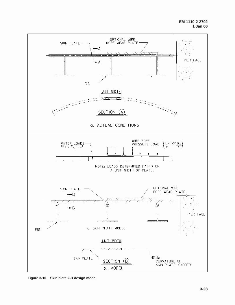
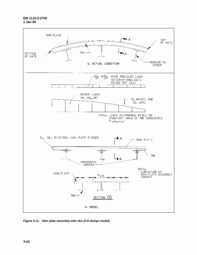
(1) Skin plate assembly. For the 2-D approximate model, the skin plate and ribs are assumed to havezero curvature. The skin plate serves two functions. First, each unit width of skin plate is assumed to actas a continuous beam spanning the ribs in the horizontal direction (Figure 3-10). Second, the skin plateacts as the upstream flange of the ribs. The ribs, with the skin plate flange, are continuous vertical beamsthat are supported by the horizontal girders (Figure 3-11). A portion of the skin plate is considered to actas the upstream flange of the rib (paragraph 3-5.b(2)).
(a) Boundary conditions. Boundary conditions consist of simple supports located at each rib for theskin plate and at each girder for the rib members.
(b) Loads. Loading on the skin plate assembly consists of various combinations of factored loads andgate reaction loads. Factored loads consist of 1.2H or 1.4H, 1.2 WA, 1.0E, kII, and 1.2Q3/r, and gatereaction loads include Rs and RQ/r. H, WA, E, I, and Q3 are defined in paragraph 3-4.b, r is the gate radius,Rs is the sill reaction load at the bottom of the skin plate (load case 1 gate closed), and RQ is the wire ropereaction load (for load cases 2 and 3 for gates with a wire rope hoist). The factored loads shall be appliedin accordance with paragraph 3-4.b(2). Gate reaction loads RS and RQ/r are determined by equilibrium ofthe end frame model for each appropriate load condition (paragraph 3-5.a(3)) and are not factored sincethey are a function of other factored loads. For skin plate design, loads are determined based on a unitwidth of plate, and it is not considered necessary to include I and RS. For the rib model, the magnitude forloads is determined based on the tributary area of the rib. For each rib, the tributary portion of RS isresolved into a radial component that is applied as a concentrated load at the end of the rib cantilever, and atangential component that is applied as an axial force. Although not applied directly, all loads described inparagraph 3-4.b can affect rib member forces, since the reaction forces at the sill or under the wire ropeinclude the effects of trunnion friction Ft, hydraulic machinery loads Q1 and Q2, and gravity loads C, M,and D as defined in paragraph 3-4.b.
(c) Results. Analysis of the skin plate model will yield the calculated stresses and out-of-planedeflections necessary to size the skin plate in accordance with paragraphs 3-4.c(1) and 3-6. Analysis of therib model yields the calculated moments necessary for rib design in accordance with paragraph 3-4.c andreactions are the girder loading for the girder frame model.
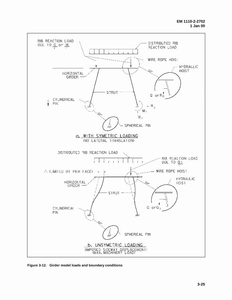
(2) Girder frame model. The 2-D analytical model is a single-story frame consisting of beammembers that simulate the horizontal girder and two columns that represent the corresponding end framestruts (Figure 3-12). The strong axes of the struts are oriented to resist flexural forces in the plane of theframe. The model shown in Figure 3-12a applies for all load cases described in paragraph 3-4.b exceptthe unsymmetric load cases 3 and 4. For these cases, the analytical model should include applied loadswith an imposed lateral displacement to represent side sway of the frame (Figure 3-12b). For load case 3,the lateral displacement should be consistent with the expected displacement as determined by anappropriate analysis (paragraph 3-5.e). For load case 4, the maximum displacement (lateral displacementto the pier face) should be applied. For all load cases except load case 4, the frame is not braced againstside sway and the analysis should be conducted accordingly (AISC (1994), Chapter C). For load case 4,the frame can be assumed to be braced with the maximum displacement applied.
(a) Boundary conditions. The supports for the structure are at the bottom of the columns or struts andshould be modeled to simulate actual conditions. Where cylindrical pins are used at the trunnion, a fixed
EM 1110-2-27021 Jan 00
3-23
Figure 3-10. Skin plate 2-D design model
EM 1110-2-27021 Jan 00
3-24
Figure 3-11. Skin plate assembly with ribs (2-D design model)
EM 1110-2-27021 Jan 00
3-25
Figure 3-12. Girder model loads and boundary conditions
EM 1110-2-27021 Jan 00
3-26
support should be assumed and where spherical bearings are used at the trunnion, a pinned support shouldbe assumed.
(b) Loads. The girders support the skin plate assembly and loads to the girder are applied through theribs. Therefore, for each load combination, girder loading is based on reaction forces from the rib model. A uniformly distributed load equivalent to the rib reactions distributed over each tributary area is appliedalong the length of the girder. This distributed load does not require a load factor, since the rib reactionsare a function of factored loads. For gates with wire rope hoists, a concentrated load equal to the reactionfor the rib that supports the wire rope should be applied to the girder at the corresponding rib location. Theconcentrated load is due to a distributed rib load equal to 1.2Q/r for load cases 4 and 5 or RQ/r for loadcases 2 and 3 (RQ is determined by the end frame model described in paragraph 3-5.a(3)). For hydraulichoists, the cylinder force load should be applied at the cylinder connection location (for most cases on thestrut near the girder). This force is equal to 1.2Q for load cases 1, 4, and 5 or the cylinder force asdetermined by the end frame model analysis for load cases 2 and 3. All loads described in paragraph 3-4.baffect the girder frame member forces since components of each load are transferred through the ribs. It isassumed that girder lateral bracing resists girder torsional forces that are caused by gravity loads.
(c) Results. The girder frame analysis results include all design forces and deflections for the girder,flexural design forces about strong axis of the struts, and reactions that simulate lateral thrust Rz into thepier and moment at the trunnion My (Figure 3-12). The lateral thrust force Rz induces friction forces thatare a component of trunnion friction moment Ft as discussed in paragraph 3-4.b(1)(f). The effect of Rz onFT should be considered in the analysis of the end frame model. For gates with parallel end frames, theeffect of Rz may be negligible. However, Rz is more significant for gates with inclined end frames, since Rz
includes a component of the strut axial loads.
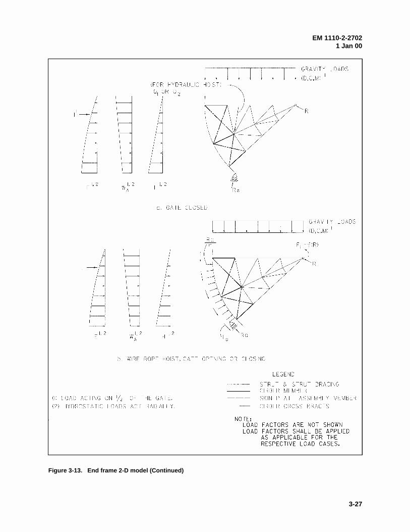
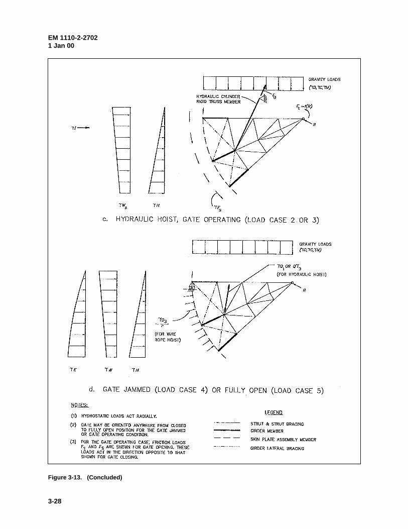
(3) End frame model. The analytical model for the end frame consists of elements to simulate strutsand strut bracing, girders (webs), girder lateral bracing, and the skin plate assembly (Figure 3-13). Strutsare modeled with frame elements, and bracing members are modeled with either frame or truss elements tobe consistent with connection details. The elements that represent the skin plate assembly and girder websare included in the model only to transfer loads and to maintain correct geometry. These elements shouldbe relatively stiff compared to other elements. The girder members should be simulated by truss elementsso the girder lateral bracing elements resist all forces transverse to the girder. (This will ensure thatbracing is proportioned so that girder torsion is limited.) The assumed boundary conditions, loading, andmodel geometry are shown by Figure 3-13 for: a) gate closed (load case 1); b) gate operating with wirerope hoist (load cases 2 and 3); c) gate operating with hydraulic cylinder hoist (load cases 2 and 3); andd) gate jammed (load case 4) or raised to stops (load case 5). Boundary conditions and loading describedin the following paragraphs are based on assumptions discussed in paragraph 3-4.b(2). The purpose of theend frame model is: a) to determine the sill reaction load RS, operating machinery reaction load RQ, andtrunnion reaction R; and b) to determine end frame member design forces.
(a) Boundary conditions. For each model described by Figure 3-13, the trunnion is modeled as a pinfree to rotate with no translation. For the gate-closed case, the boundary conditions for gates with wirerope or hydraulic hoists are identical as shown by Figure 3-13a. The gate is supported by the trunnion(modeled as a pin) and the sill. The sill boundary condition consists of a roller-pin free to translate tangentto the sill. For a 3-D model, the boundary condition along the sill should resist compression only (i.e.,allow for deformation near the center of a gate that will likely result between the sill and gate bottom).There is no boundary condition for the hoist; a hoist force is treated as an external load. For gate-operatingcases (Figures 3-13b and 3-13c), the gate is supported by the trunnion (modeled as a pin) and the hoist.(For this case, the hoist force is a reaction and not a load as discussed in paragraph 3-4.b(2)(f)). For wire
EM 1110-2-27021 Jan 00
3-27
Figure 3-13. End frame 2-D model (Continued)
EM 1110-2-27021 Jan 00
3-28
Figure 3-13. (Concluded)
EM 1110-2-27021 Jan 00
3-29
rope hoists (Figure 3-13b), the boundary condition where the wire rope is attached to the skin plateassembly is modeled as a roller-pin support that is free to translate in the radial direction. For gates with ahydraulic hoist (Figure 3-13c), the cylinder is simulated by a rigid (very stiff) truss element positionedbetween the location of the cylinder connection to the end frame and the cylinder trunnion location. Thisis analogous to a roller-pin support located at the cylinder connection that is free to translate perpendicularto the hoist cylinder. (The cylinder connection to the end frame may include eccentricity out of the planeof the model depending on how the connection is detailed. If this is significant it should be accounted forin the design.) For the gate jammed or fully opened cases (Figure 3-13d), the gate is supported by thetrunnion (modeled as a pin) and is restrained from rotation by the pier or some obstruction (gate jammed)or the gate stops (gate fully opened). The boundary condition to restrain rotation is a roller-pin supportfree to translate in the radial direction and located where the elements for the top girder and skin plateintersect or at another appropriate position along the skin plate.
(b) Loads. For each load case, the appropriate analytical model should include the combinations offactored loads as required by paragraph 3-4.b(2). With the gate closed, appropriate combinations of loads(1.2 or 1.4)H, 1.2D, 1.6(C + M), 1.2(Q1 or Q2), 1.2WA, kII, and 1.0E are included as illustrated byFigure 3-13a. For wire rope systems, there is no force in the rope, so no operating machinery loads areincluded. For hydraulic hoist systems, the operating machinery force is treated as a load Q1 or Q2 since themachinery is not considered as a support. For load cases 2 and 3 (Figures 3-13b and 3-13c), loads includeappropriate combinations of 1.4H, 1.2D, 1.6(C + M), 1.4Fs, 1.0Ft, 1.2WA, and kII. Friction loads arepresent due to gate motion. The side-seal friction force Fs is applied along the perimeter of the skin plate,and trunnion friction moment Ft is applied at the pin support. Operating machinery loads Q (as defined inparagraph 3-4.b(1)) do not apply because the hoists serve as supports. However, for wire rope systems, theanalysis must include the distributed load RQ/r that acts radially wherever the rope contacts the skin plate. The wire rope tension is equal to the hoist reaction RQ. Because external loads RQ/r and the trunnionfriction load Ft are a function of reaction forces RQ and R (and the reactions are a function of externalloads), a special analysis such as the iterative approach described in paragraph 3-5.a(3)(d) is necessary todetermine the equilibrium state. As defined in paragraph 3-4.b(1)(f), the trunnion friction force Ft includesthe effect of the end frame trunnion reaction R (parallel to the pier or abutment face) and the lateral strutreaction Rz (component perpendicular to the pier). Rz is estimated by analysis of the girder frame model. For load cases 4 and 5 (Figure 3-13d), loads include appropriate combinations of 1.4H, 1.2D, 1.6(C + M),1.3W, 1.2Q1 or 1.2Q3, and 1.0E. For these cases, operating machinery loads Q are included since thehoists are not considered gate supports. For wire rope hoist systems, the analysis for load case 4 or loadcase 5 must include the factored distributed load 1.2Q3/r which acts radially wherever the rope contacts theskin plate. For hydraulic hoist systems, the analysis should include the operating machinery load 1.2Q1 or1.2Q3. (For load case 5, a downward load Q1 may not be possible when the gate is fully opened, dependingon gate arrangement.)
(c) Results. The end frame model provides strut weak axis flexural design forces, strut axial designforces, axial and flexural design forces for strut bracing, girder lateral bracing design forces, trunnionreaction forces, and operating equipment load requirements. The end frame model reaction forces Rs andRQ are utilized in the other 2-D models as described in the previous sections.
(d) Iterative determination of reaction forces. For gate-operating cases in which external forces are afunction of gate reactions, a special analysis such as iteration is necessary to determine forces and reactionsbecause the reactions are a function of the external forces. Considering load case 2 or load case 3 with awire rope hoist system, the trunnion friction moment Ft and distributed rope load RQ/r (external loads) area function of the trunnion reaction force R, and the hoist reaction force RQ. A simple procedure to conductthe iteration is as follows:
EM 1110-2-27021 Jan 00
3-30
1) Approximate the trunnion reaction R due to factored hydrostatic loading 1.4H and estimate thetrunnion friction moment Ft as a function of R, Rz (determined from the girder frame analysis), the pindiameter, and coefficient of friction.
2) Determine the hoist reaction RQ by equilibrium.
3) Recalculate the trunnion reaction R due to all appropriate factored loads (i.e., for load case 3,1.4H, 1.2D, 1.6(C + M), 1.4Fs, 1.0Ft) including the reaction load RQ/r.
4) Determine a modified trunnion friction moment Ft as a function of the modified reaction R, Rz
(unchanged), pin diameter, and coefficient of friction.
5) Repeat steps 2 through 4 until the trunnion reaction R does not change significantly.
(4) Downstream vertical truss model. Bracing members that make up the downstream vertical trussare proportioned for forces that occur when the gate is supported at one end. To determine these forcesaccurately, a 3-D analysis is required because of the complex interaction of the skin plate assembly, endframes, and bracing members. However, various 2-D models can be used to conservatively approximatethe forces. Figure 3-14 and the following paragraphs describe a recommended 2-D model. The simplifiedmodel shown in Figure 3-14b does not represent actual loading and support conditions but will provideapproximate bracing forces for the simulated condition. Continuous frame elements simulate girderflanges, and the bracing members are represented by truss elements (include only axial forces). As statedin paragraph 3-2a(2)(b), out of plane geometry is ignored, and the truss members are assumed to lie in asingle plane.
(a) Boundary conditions. With the analytical model described by Figure 3-14b, boundary conditionsdo not represent physical characteristics of the gate but provide geometric stability of the model. A roller-pin support free to translate in the horizontal direction is provided at the node where the shear load RH isapplied. This should be located at the end of the element that simulates the upper girder (near a bumperlocation or where the gate would contact the pier if rotation of the skin plate assembly were to occur). Onthe opposite corner of the model (opposite end of the lower girder), a pin support free to rotate with notranslation is applied.
(b) Loads. Model loading (Figure 3-14b) consists of a horizontal shear load RH. The magnitude of RH
as defined in Figure 3-14a is that required to maintain equilibrium with the gate subjected to vertical loadsand suspended from one end. As described by the free body diagram of Figure 3-14a, the effects offactored loads 1.2D, 1.6(C+M), and 1.4Fs are included (simulates load case 3, paragraph 3-4.b(2)(c)). Thetrunnion friction load Ft and hydrostatic loads H, do not directly cause twisting of the gate and are notconsidered.
(c) Results. Truss members are to be sized to resist the calculated axial forces as determined byanalysis of the downstream vertical truss model.
b. Skin plate assembly. The skin plate assembly consists of the skin plate and vertical ribs. Horizontal intercostals are not recommended since material savings realized in the design of the skin plateare offset by higher fabrication and maintenance costs. The designs of the skin plate and ribs are inter-related. The required skin plate thickness is dependent on the rib spacing (skin plate span), and therequired rib size is dependent on the skin plate thickness since an effective portion of skin plate acts as arib flange.
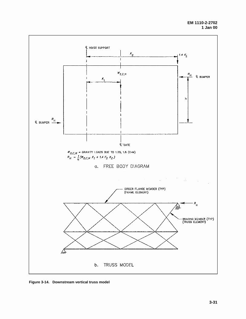
EM 1110-2-27021 Jan 00
3-31
Figure 3-14. Downstream vertical truss model
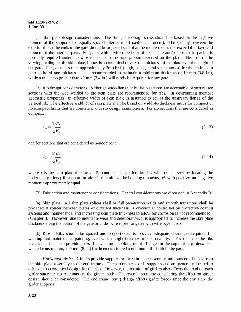
EM 1110-2-27021 Jan 00
3-32
(1) Skin plate design considerations. The skin plate design stress should be based on the negativemoment at the supports for equally spaced interior ribs (fixed-end moment). The spacing between theexterior ribs at the ends of the gate should be adjusted such that the moment does not exceed the fixed-endmoment of the interior spans. For gates with a wire rope hoist, thicker plate and/or closer rib spacing isnormally required under the wire rope due to the rope pressure exerted on the plate. Because of thevarying loading on the skin plate, it may be economical to vary the thickness of the plate over the height ofthe gate. For gates less than approximately 3m (10 ft) high, it is generally economical for the entire skinplate to be of one thickness. It is recommended to maintain a minimum thickness of 10 mm (3/8 in.),while a thickness greater than 20 mm (3/4 in.) will rarely be required for any gate.
(2) Rib design considerations. Although wide-flange or built-up sections are acceptable, structural teesections with the web welded to the skin plate are recommended for ribs. In determining membergeometric properties, an effective width of skin plate is assumed to act as the upstream flange of thevertical rib. The effective width be of skin plate shall be based on width-to-thickness ratios for compact ornoncompact limits that are consistent with rib design assumptions. For rib sections that are considered ascompact,
y
eF
tb
187� (3-13)
and for sections that are considered as noncompact,
y
eF
tb
255� (3-14)
where t is the skin plate thickness. Economical design for the ribs will be achieved by locating thehorizontal girders (rib support locations) to minimize the bending moments, Mu with positive and negativemoments approximately equal.
(3) Fabrication and maintenance considerations. General considerations are discussed in Appendix B.
(a) Skin plate. All skin plate splices shall be full penetration welds and smooth transitions shall beprovided at splices between plates of different thickness. Corrosion is controlled by protective coatingsystems and maintenance, and increasing skin plate thickness to allow for corrosion is not recommended. (Chapter 8.) However, due to inevitable wear and deterioration, it is appropriate to increase the skin platethickness along the bottom of the gate or under wire ropes for gates with wire rope hoists.
(b) Ribs. Ribs should be spaced and proportioned to provide adequate clearances required forwelding and maintenance painting, even with a slight increase in steel quantity. The depth of the ribsmust be sufficient to provide access for welding or bolting the rib flanges to the supporting girders. Forwelded construction, 200 mm (8 in.) has been considered a minimum rib depth in the past.
c. Horizontal girder. Girders provide support for the skin plate assembly and transfer all loads fromthe skin plate assembly to the end frames. The girders act as rib supports and are generally located toachieve an economical design for the ribs. However, the location of girders also affects the load on eachgirder since the rib reactions are the girder loads. The overall economy considering the effect on girderdesign should be considered. The end frame (strut) design affects girder forces since the struts are thegirder supports.
EM 1110-2-27021 Jan 00
3-33
(1) Design considerations. Horizontal girders are singly or doubly symmetric prismatic members thatare designed primarily for flexure about their major axis. The distribution of flexure along the length ofthe girder is significantly influenced by the orientation of the end frames. Maximum girder moments willresult with struts that are parallel to the pier face. The maximum girder moment is reduced (moments areredistributed) if the struts are inclined and will be minimized if the struts intersect the girder atapproximately one-fifth the gate width from the pier face. With inclined struts, the limit state of lateraltorsional buckling of the girder should be checked since a significant length of the downstream flange of the girder will be in compression. The unsupported length of the downstream flange is the distancebetween supports consisting of downstream vertical truss members and the end frame strut. (The upstreamflange is laterally supported nearly continuously by the vertical ribs.) The downstream vertical truss isdesigned primarily to resist forces that occur when the gate is supported at only one end (paragraph 3-5.e.)and also provides lateral stability and resistance to torsional buckling for the girders. The tension flange ofcritical girders may be fracture critical and should be designed and fabricated accordingly (paragraph 3-8).
(2) Fabrication and maintenance considerations. Appendix B includes general guidance for inspec-tion and welding. Girders may be rolled sections or built-up plate girders. The rib-to-girder connection,girder-to-strut connection, and bracing connections should be detailed to minimize concern for fracture(Appendix B). Drain holes with smooth edges should be provided in the girder webs at locations mostappropriate for drainage. All stiffeners shall be coped. Use of a minimum number of girders will simplifyfabrication and erection and facilitate maintenance. However, the overall economy considering the designof the skin plate assembly should not be compromised.
d. End frames. The end frames transfer loads from the girders and skin plate assembly to thetrunnion. End frames include the struts and associated bracing and the trunnion hub flange plates. Thearrangement and orientation of the end frames affects the magnitude and distribution of end frame andhorizontal girder forces, trunnion fabrication, trunnion pin binding, and thrust forces into the pier. Toachieve an economical design, these effects should be recognized considering all applicable load cases.
(1) Design considerations. Struts include flexure about both axes and significant axial forces. With a3-D analysis, all forces are obtained from the same model. However, if a 2-D analysis as described inparagraph 3-5.a is utilized, the strut strong axis moments shall be determined from the girder model andthe axial forces and weak axis moments shall be determined by the end frame model. End frame bracingshould be spaced to achieve adequate weak axis slenderness ratios for the struts and must be designed toresist calculated forces. Bracing members may include significant flexural forces depending on membersizes, connection rigidity, and trunnion friction. Critical bracing members subject to flexural tension canbe fracture critical and should be designed and fabricated accordingly (paragraph 3-8). Trunnion hubflanges shall be proportioned to resist the strut flexural, shear, and axial loads.
(2) Fabrication and maintenance considerations. Strut bracing members can be structural tee or wideflange sections; however, using wide flange sections with the same depth as the struts generally facilitatesfabrication of connections. Trunnion hub flanges should be proportioned to provide a surfaceperpendicular to each strut with clearance provided between the ends of intersecting struts (Figure 3-15).Critical connections include the strut-to-girder connection (discussed in Appendix B) and the strut-to-trunnion hub flanges. The latter connection generally involves full-penetration butt splices involving thickplates, and welding requirements should be developed to minimize associated problems (Appendix B). Thelayout of end frames, parallel to the pier or inclined, is an important consideration regarding the overalldesign of the structure. Each configuration has unique advantages and disadvantages.
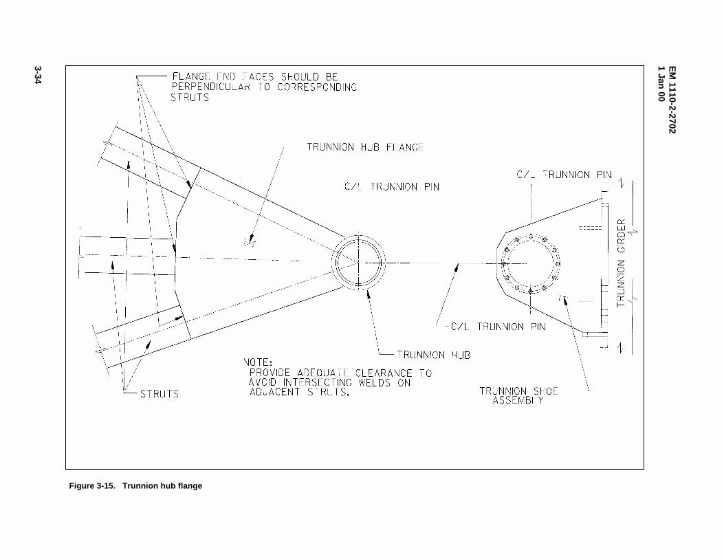
EM
1110-2-27021 Jan
00
3-34
Figure 3-15. Trunnion hub flange
EM 1110-2-27021 Jan 00
3-35
(a) Parallel end frames. End frames that are parallel to the pier and perpendicular to the horizontalgirders are positioned such that interference to flow and debris accumulation on the struts is minimized.Fabrication and layout is relatively simple and struts that are parallel to the pier face transfer minimallateral thrust into the piers. However, economy of the gate is sacrificed due to large flexural loads in thestruts and girders, and clearance for maintenance painting between the pier and struts is limited.
(b) Inclined end frames. By inclining the end frames from the pier face, flexural forces areredistributed and the girder and strut flexural forces are reduced. The point of intersection of the strut andgirder can be selected such that the girder moment at midspan is equal in magnitude to the cantilevermoment as discussed in paragraph 3-5.c. With this arrangement, maximum economy of the girder design isachieved, and flexure in the end frames is minimal. A second option is to locate the intersection wherethere would be zero rotation in the horizontal girder. This would theoretically eliminate bending in the endframes. The side thrust component of the gate reaction introduced by inclining the end frames istransmitted directly to the pier or is resisted by a trunnion tie. Where the lateral thrust appreciablyincreases the pier requirements, it may be preferred to reduce the degree of inclination to achieve a moreeconomical design. While inclined end frames are usually desirable for flood control projects, they areoften not feasible for navigation dam projects where floating debris is a concern.
(c) Inclined frame layout. With inclined end frames, there are two options for layout of the struts. Thestruts can be positioned in a single vertical plane, or such that the girder end of each strut is an equalhorizontal distance from the pier face. Placing struts in the same plane is generally recommended sincefabrication is simplified and it will usually be cost effective.
1) Struts equal distance from pier. The struts can be positioned such that the connection betweeneach strut and its corresponding horizontal girder is an equal horizontal distance from the pier face. In thiscase, the centerlines of the struts will form a conical surface with the apex at the trunnion. This results incomplex fabrication of the strut-to-trunnion hub flange connection, since the struts are rotated with respectto one another and do not lie in one plane. However, this configuration has been widely used.
2) Struts positioned in a single plane. With struts positioned in a single vertical plane, only two strutscan be at the same horizontal distance from the pier face. For gates with more than two girders, this resultsin differing support locations for the horizontal girders. However, fabrication of the strut-to-trunnion hubflange connection is simplified since all struts fall in a single plane. (This configuration is the only optionfor a vertical girder gate, since the struts and the vertical girder must fall in one plane.)
e. Downstream vertical truss. The primary structural purpose of the downstream vertical trussbracing members is to provide torsional rigidity for the condition when the gate is supported at one end. Italso provides gate rigidity for resisting gravity loads with symmetric hoist support conditions, lateralbracing for the horizontal girders, and structural rigidity during field erection.
(1) Design considerations. For design purposes, bracing members should be sized to resist axialforces determined as described in paragraph 3-5.a(4). This procedure is conservative since the verticalsupport of the end frames and additional torsional rigidity of the skin plate assembly are ignored. Wherepractical, bracing should be placed in positions appropriate to provide lateral support to the girders. Forgates that have a low height-to-width ratio, it may not be practical to design a bracing system that wouldprevent significant lateral displacements if the gate were supported on only one side. In these cases it maybe necessary to provide side bumpers to limit lateral movement as described in paragraph 3-6.b(1).
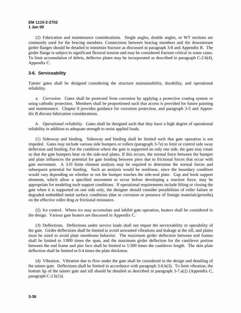
EM 1110-2-27021 Jan 00
3-36
(2) Fabrication and maintenance considerations. Single angles, double angles, or WT sections arecommonly used for the bracing members. Connections between bracing members and the downstreamgirder flanges should be detailed to minimize fracture as discussed in paragraph 3-8 and Appendix B. Thegirder flange is subject to significant flexural tension and may be considered fracture critical in some cases.To limit accumulation of debris, deflector plates may be incorporated as described in paragraph C-2.b(4),Appendix C.
3-6. Serviceability
Tainter gates shall be designed considering the structure maintainability, durability, and operationalreliability.
a. Corrosion. Gates shall be protected from corrosion by applying a protective coating system orusing cathodic protection. Members shall be proportioned such that access is provided for future paintingand maintenance. Chapter 8 provides guidance for corrosion protection, and paragraph 3-5 and Appen-dix B discuss fabrication considerations.
b. Operational reliability. Gates shall be designed such that they have a high degree of operationalreliability in addition to adequate strength to resist applied loads.
(1) Sidesway and binding. Sidesway and binding shall be limited such that gate operation is notimpeded. Gates may include various side bumpers or rollers (paragraph 3-7e) to limit or control side swaydeflection and binding. For the condition where the gate is supported on only one side, the gate may rotateso that the gate bumpers bear on the side-seal plates. If this occurs, the normal force between the bumperand plate influences the potential for gate binding between piers due to frictional forces that occur withgate movement. A 3-D finite element analysis may be required to determine the normal forces andsubsequent potential for binding. Such an analysis would be nonlinear, since the boundary conditionwould vary depending on whether or not the bumper touches the side-seal plate. Gap and hook supportelements, which allow a specified movement to occur before developing a reaction force, may beappropriate for modeling such support conditions. If operational requirements include lifting or closing thegate when it is supported on one side only, the designer should consider possibilities of roller failure ordegraded embedded metal surface conditions (due to corrosion or presence of foreign materials/growths)on the effective roller drag or frictional resistance.
(2) Ice control. Where ice may accumulate and inhibit gate operation, heaters shall be considered inthe design. Various gate heaters are discussed in Appendix C.
(3) Deflections. Deflections under service loads shall not impair the serviceability or operability ofthe gate. Girder deflections shall be limited to avoid unwanted vibrations and leakage at the sill, and platesmust be sized to avoid plate membrane behavior. The maximum girder deflection between end framesshall be limited to 1/800 times the span, and the maximum girder deflection for the cantilever portionbetween the end frame and pier face shall be limited to 1/300 times the cantilever length. The skin platedeflection shall be limited to 0.4 times the plate thickness.
(4) Vibration. Vibration due to flow under the gate shall be considered in the design and detailing ofthe tainter gate. Deflections shall be limited in accordance with paragraph 3-6.b(3). To limit vibration, thebottom lip of the tainter gate and sill should be detailed as described in paragraph 3-7.a(2) (Appendix C,paragraph C-2.b(1)).
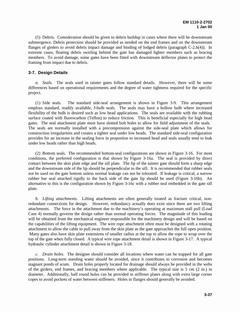
EM 1110-2-27021 Jan 00
3-37
(5) Debris. Consideration should be given to debris buildup in cases where there will be downstreamsubmergence. Debris protection should be provided as needed on the end frames and on the downstreamflanges of girders to avoid debris impact damage and binding of lodged debris (paragraph C-2.b(4)). Inextreme cases, floating debris swirling behind the gate has damaged lighter members such as bracingmembers. To avoid damage, some gates have been fitted with downstream deflector plates to protect theframing from impact due to debris.
3-7. Design Details
a. Seals. The seals used in tainter gates follow standard details. However, there will be somedifferences based on operational requirements and the degree of water tightness required for the specificproject.
(1) Side seals. The standard side-seal arrangement is shown in Figure 3-9. This arrangementemploys standard, readily available, J-bulb seals. The seals may have a hollow bulb where increasedflexibility of the bulb is desired such as low head applications. The seals are available with the rubbingsurface coated with fluorocarbon (Teflon) to reduce friction. This is beneficial especially for high headgates. The seal attachment plate must have slotted bolt holes to allow for field adjustment of the seals. The seals are normally installed with a precompression against the side-seal plate which allows forconstruction irregularities and creates a tighter seal under low heads. The standard side-seal configurationprovides for an increase in the sealing force in proportion to increased head and seals usually tend to leakunder low heads rather than high heads.
(2) Bottom seals. The recommended bottom-seal configurations are shown in Figure 3-16. For mostconditions, the preferred configuration is that shown by Figure 3-16a. The seal is provided by directcontact between the skin plate edge and the sill plate. The lip of the tainter gate should form a sharp edgeand the downstream side of the lip should be perpendicular to the sill. It is recommended that rubber sealsnot be used on the gate bottom unless normal leakage can not be tolerated. If leakage is critical, a narrowrubber bar seal attached rigidly to the back side of the gate lip should be used (Figure 3-16b). Analternative to this is the configuration shown by Figure 3-16c with a rubber seal embedded in the gate sillplate.
b. Lifting attachments. Lifting attachments are often generally treated as fracture critical, non-redundant connections for design. However, redundancy actually does exist since there are two liftingattachments. The force in the attachment due to the machinery’s operating at maximum stall pull (LoadCase 4) normally governs the design rather than normal operating forces. The magnitude of this loadingwill be obtained from the mechanical engineer responsible for the machinery design and will be based onthe capabilities of the lifting equipment. The wire rope attachment often must be designed with a rotatingattachment to allow the cable to pull away from the skin plate as the gate approaches the full open position. Many gates also have skin plate extensions of smaller radius at the top to allow the rope to wrap over thetop of the gate when fully closed. A typical wire rope attachment detail is shown in Figure 3-17. A typicalhydraulic cylinder attachment detail is shown in Figure 3-18.
c. Drain holes. The designer should consider all locations where water can be trapped for all gatepositions. Long-term standing water should be avoided, since it contributes to corrosion and becomesstagnant ponds of scum. Drain holes properly located for drainage should always be provided in the websof the girders, end frames, and bracing members where applicable. The typical size is 5 cm (2 in.) indiameter. Additionally, half round holes can be provided in stiffener plates along with extra large cornercopes to avoid pockets of water between stiffeners. Holes in flanges should generally be avoided.
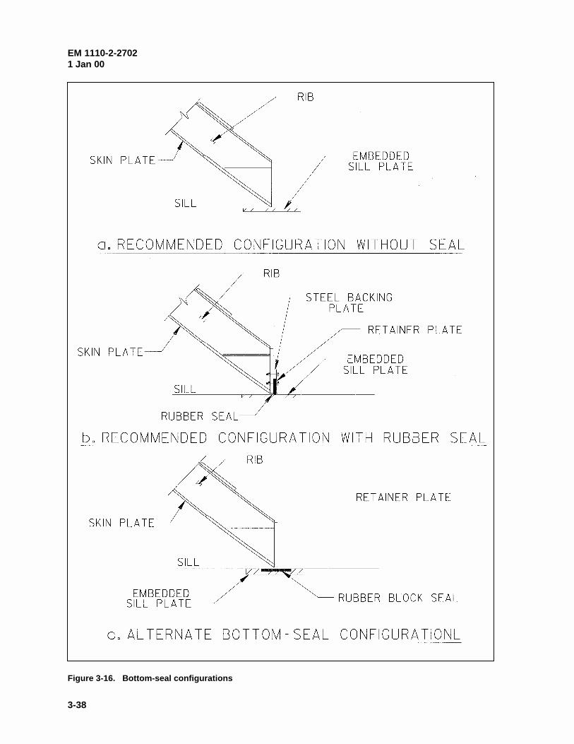
EM 1110-2-27021 Jan 00
3-38
Figure 3-16. Bottom-seal configurations
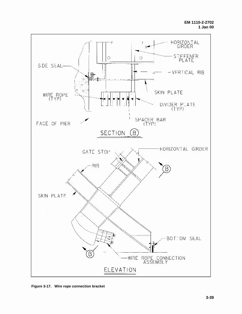
EM 1110-2-27021 Jan 00
3-39
Figure 3-17. Wire rope connection bracket
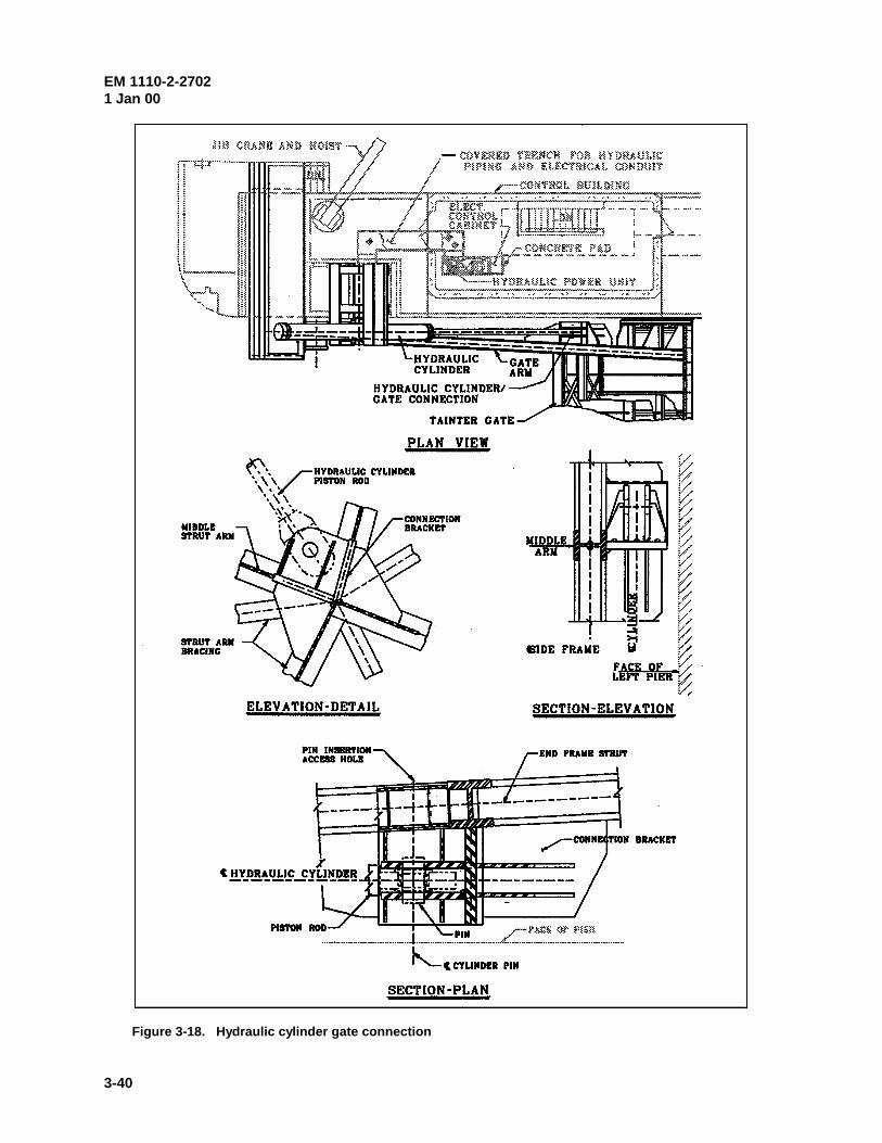
EM 1110-2-27021 Jan 00
3-40
Figure 3-18. Hydraulic cylinder gate connection
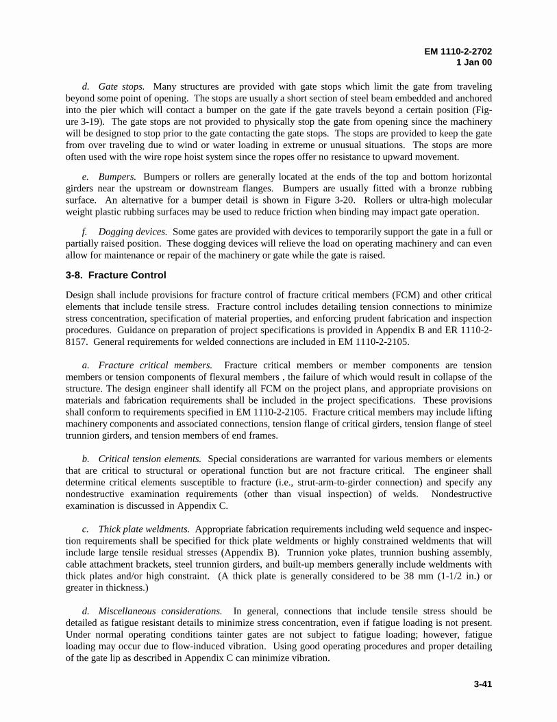
EM 1110-2-27021 Jan 00
3-41
d. Gate stops. Many structures are provided with gate stops which limit the gate from travelingbeyond some point of opening. The stops are usually a short section of steel beam embedded and anchoredinto the pier which will contact a bumper on the gate if the gate travels beyond a certain position (Fig-ure 3-19). The gate stops are not provided to physically stop the gate from opening since the machinerywill be designed to stop prior to the gate contacting the gate stops. The stops are provided to keep the gatefrom over traveling due to wind or water loading in extreme or unusual situations. The stops are moreoften used with the wire rope hoist system since the ropes offer no resistance to upward movement.
e. Bumpers. Bumpers or rollers are generally located at the ends of the top and bottom horizontalgirders near the upstream or downstream flanges. Bumpers are usually fitted with a bronze rubbingsurface. An alternative for a bumper detail is shown in Figure 3-20. Rollers or ultra-high molecularweight plastic rubbing surfaces may be used to reduce friction when binding may impact gate operation.
f. Dogging devices. Some gates are provided with devices to temporarily support the gate in a full orpartially raised position. These dogging devices will relieve the load on operating machinery and can evenallow for maintenance or repair of the machinery or gate while the gate is raised.
3-8. Fracture Control
Design shall include provisions for fracture control of fracture critical members (FCM) and other criticalelements that include tensile stress. Fracture control includes detailing tension connections to minimizestress concentration, specification of material properties, and enforcing prudent fabrication and inspectionprocedures. Guidance on preparation of project specifications is provided in Appendix B and ER 1110-2-8157. General requirements for welded connections are included in EM 1110-2-2105.
a. Fracture critical members. Fracture critical members or member components are tensionmembers or tension components of flexural members , the failure of which would result in collapse of thestructure. The design engineer shall identify all FCM on the project plans, and appropriate provisions onmaterials and fabrication requirements shall be included in the project specifications. These provisionsshall conform to requirements specified in EM 1110-2-2105. Fracture critical members may include liftingmachinery components and associated connections, tension flange of critical girders, tension flange of steeltrunnion girders, and tension members of end frames.
b. Critical tension elements. Special considerations are warranted for various members or elementsthat are critical to structural or operational function but are not fracture critical. The engineer shalldetermine critical elements susceptible to fracture (i.e., strut-arm-to-girder connection) and specify anynondestructive examination requirements (other than visual inspection) of welds. Nondestructiveexamination is discussed in Appendix C.
c. Thick plate weldments. Appropriate fabrication requirements including weld sequence and inspec-tion requirements shall be specified for thick plate weldments or highly constrained weldments that willinclude large tensile residual stresses (Appendix B). Trunnion yoke plates, trunnion bushing assembly,cable attachment brackets, steel trunnion girders, and built-up members generally include weldments withthick plates and/or high constraint. (A thick plate is generally considered to be 38 mm (1-1/2 in.) orgreater in thickness.)
d. Miscellaneous considerations. In general, connections that include tensile stress should bedetailed as fatigue resistant details to minimize stress concentration, even if fatigue loading is not present.Under normal operating conditions tainter gates are not subject to fatigue loading; however, fatigueloading may occur due to flow-induced vibration. Using good operating procedures and proper detailingof the gate lip as described in Appendix C can minimize vibration.
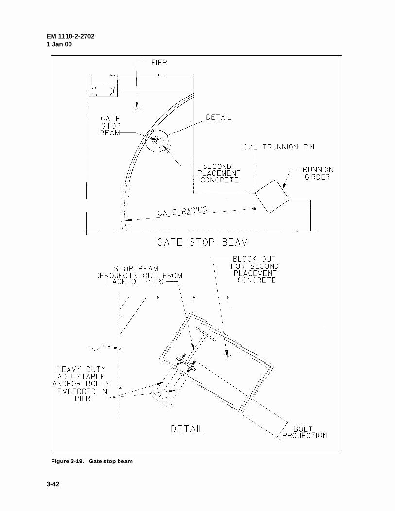
EM 1110-2-27021 Jan 00
3-42
Figure 3-19. Gate stop beam
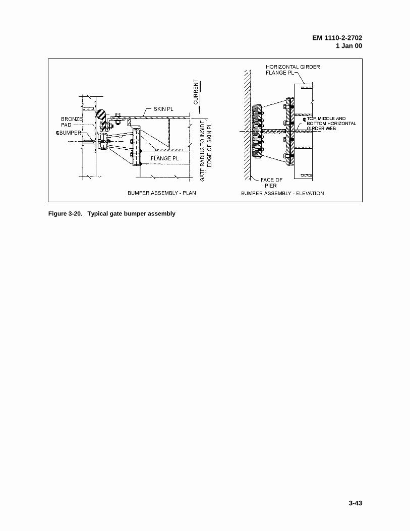
EM 1110-2-27021 Jan 00
3-43
Figure 3-20. Typical gate bumper assembly
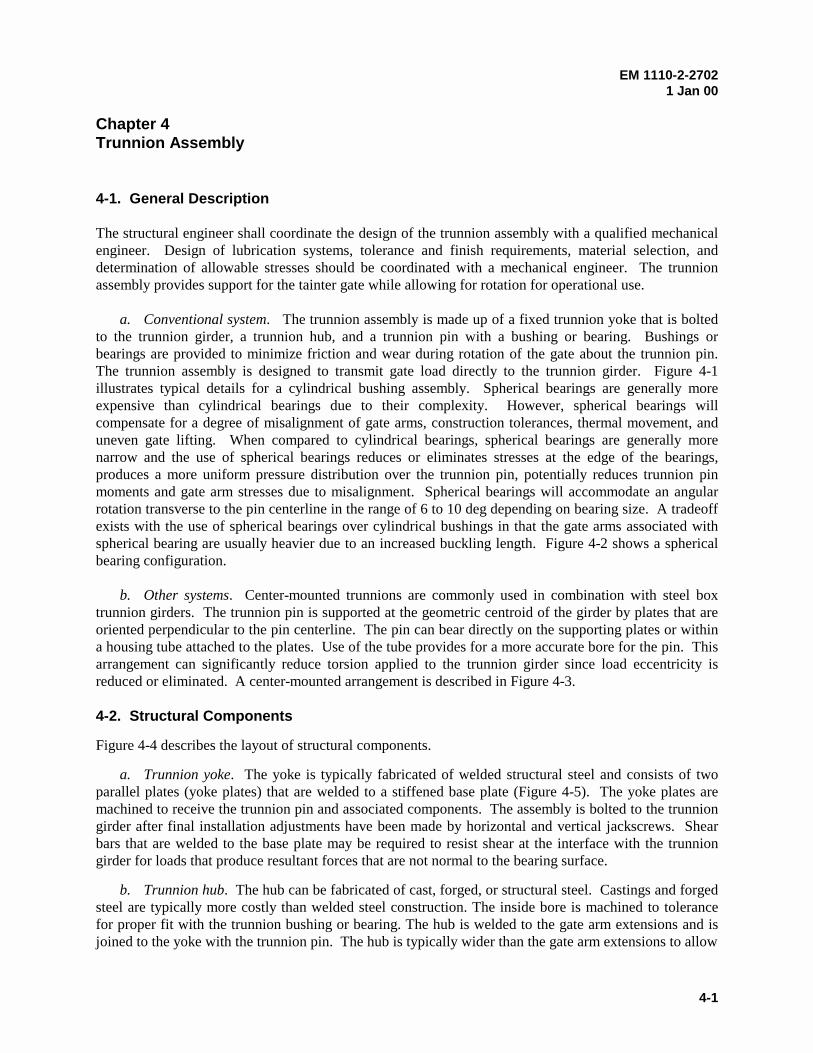
EM 1110-2-27021 Jan 00
4-1
Chapter 4Trunnion Assembly
4-1. General Description
The structural engineer shall coordinate the design of the trunnion assembly with a qualified mechanicalengineer. Design of lubrication systems, tolerance and finish requirements, material selection, anddetermination of allowable stresses should be coordinated with a mechanical engineer. The trunnionassembly provides support for the tainter gate while allowing for rotation for operational use.
a. Conventional system. The trunnion assembly is made up of a fixed trunnion yoke that is boltedto the trunnion girder, a trunnion hub, and a trunnion pin with a bushing or bearing. Bushings orbearings are provided to minimize friction and wear during rotation of the gate about the trunnion pin.The trunnion assembly is designed to transmit gate load directly to the trunnion girder. Figure 4-1illustrates typical details for a cylindrical bushing assembly. Spherical bearings are generally moreexpensive than cylindrical bearings due to their complexity. However, spherical bearings willcompensate for a degree of misalignment of gate arms, construction tolerances, thermal movement, anduneven gate lifting. When compared to cylindrical bearings, spherical bearings are generally morenarrow and the use of spherical bearings reduces or eliminates stresses at the edge of the bearings,produces a more uniform pressure distribution over the trunnion pin, potentially reduces trunnion pinmoments and gate arm stresses due to misalignment. Spherical bearings will accommodate an angularrotation transverse to the pin centerline in the range of 6 to 10 deg depending on bearing size. A tradeoffexists with the use of spherical bearings over cylindrical bushings in that the gate arms associated withspherical bearing are usually heavier due to an increased buckling length. Figure 4-2 shows a sphericalbearing configuration.
b. Other systems. Center-mounted trunnions are commonly used in combination with steel boxtrunnion girders. The trunnion pin is supported at the geometric centroid of the girder by plates that areoriented perpendicular to the pin centerline. The pin can bear directly on the supporting plates or withina housing tube attached to the plates. Use of the tube provides for a more accurate bore for the pin. Thisarrangement can significantly reduce torsion applied to the trunnion girder since load eccentricity isreduced or eliminated. A center-mounted arrangement is described in Figure 4-3.
4-2. Structural Components
Figure 4-4 describes the layout of structural components.
a. Trunnion yoke. The yoke is typically fabricated of welded structural steel and consists of twoparallel plates (yoke plates) that are welded to a stiffened base plate (Figure 4-5). The yoke plates aremachined to receive the trunnion pin and associated components. The assembly is bolted to the trunniongirder after final installation adjustments have been made by horizontal and vertical jackscrews. Shearbars that are welded to the base plate may be required to resist shear at the interface with the trunniongirder for loads that produce resultant forces that are not normal to the bearing surface.
b. Trunnion hub. The hub can be fabricated of cast, forged, or structural steel. Castings and forgedsteel are typically more costly than welded steel construction. The inside bore is machined to tolerancefor proper fit with the trunnion bushing or bearing. The hub is welded to the gate arm extensions and isjoined to the yoke with the trunnion pin. The hub is typically wider than the gate arm extensions to allow
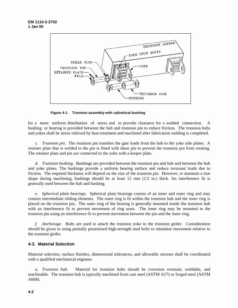
EM 1110-2-27021 Jan 00
4-2
for a more uniform distribution of stress and to provide clearance for a welded connection. Abushing or bearing is provided between the hub and trunnion pin to reduce friction. The trunnion hubsand yokes shall be stress relieved by heat treatment and machined after fabrication welding is completed.
c. Trunnion pin. The trunnion pin transfers the gate loads from the hub to the yoke side plates. Aretainer plate that is welded to the pin is fitted with shear pin to prevent the trunnion pin from rotating.The retainer plate and pin are connected to the yoke with a keeper plate.
d. Trunnion bushing. Bushings are provided between the trunnion pin and hub and between the huband yoke plates. The bushings provide a uniform bearing surface and reduce torsional loads due tofriction. The required thickness will depend on the size of the trunnion pin. However, to maintain a trueshape during machining, bushings should be at least 12 mm (1/2 in.) thick. An interference fit isgenerally used between the hub and bushing.
e. Spherical plain bearings. Spherical plain bearings consist of an inner and outer ring and maycontain intermediate sliding elements. The outer ring is fit within the trunnion hub and the inner ring isplaced on the trunnion pin. The outer ring of the bearing is generally mounted inside the trunnion hubwith an interference fit to prevent movement of ring seats. The inner ring may be mounted to thetrunnion pin using an interference fit to prevent movement between the pin and the inner ring.
f. Anchorage. Bolts are used to attach the trunnion yoke to the trunnion girder. Considerationshould be given to using partially prestressed high-strength stud bolts to minimize movement relative tothe trunnion girder.
4-3. Material Selection
Material selection, surface finishes, dimensional tolerances, and allowable stresses shall be coordinatedwith a qualified mechanical engineer.
a. Trunnion hub. Material for trunnion hubs should be corrosion resistant, weldable, andmachinable. The trunnion hub is typically machined from cast steel (ASTM A27) or forged steel (ASTMA668).
Figure 4-1. Trunnion assembly with cylindrical bushing
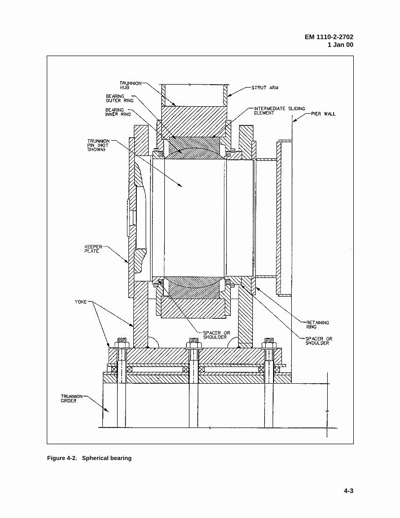
EM 1110-2-27021 Jan 00
4-3
Figure 4-2. Spherical bearing
EM 1110-2-27021 Jan 00
4-4
Figure 4-3. Center-pin mount bearing
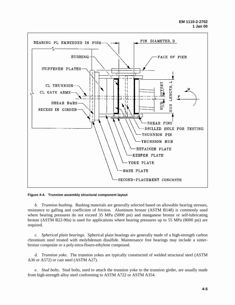
EM 1110-2-27021 Jan 00
4-5
b. Trunnion bushing. Bushing materials are generally selected based on allowable bearing stresses,resistance to galling and coefficient of friction. Aluminum bronze (ASTM B148) is commonly usedwhere bearing pressures do not exceed 35 MPa (5000 psi) and manganese bronze or self-lubricatingbronze (ASTM B22-90a) is used for applications where bearing pressures up to 55 MPa (8000 psi) arerequired.
c. Spherical plain bearings. Spherical plain bearings are generally made of a high-strength carbonchromium steel treated with molybdenum disulfide. Maintenance free bearings may include a sinter-bronze composite or a poly-tetra-flouro-ethylene compound.
d. Trunnion yoke. The trunnion yokes are typically constructed of welded structural steel (ASTMA36 or A572) or cast steel (ASTM A27).
e. Stud bolts. Stud bolts, used to attach the trunnion yoke to the trunnion girder, are usually madefrom high-strength alloy steel conforming to ASTM A722 or ASTM A354.
Figure 4-4. Trunnion assembly structural component layout
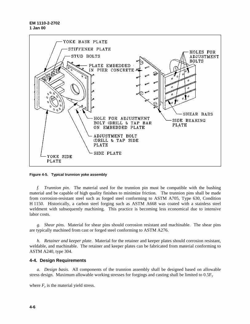
EM 1110-2-27021 Jan 00
4-6
f. Trunnion pin. The material used for the trunnion pin must be compatible with the bushingmaterial and be capable of high quality finishes to minimize friction. The trunnion pins shall be madefrom corrosion-resistant steel such as forged steel conforming to ASTM A705, Type 630, ConditionH 1150. Historically, a carbon steel forging such as ASTM A668 was coated with a stainless steelweldment with subsequently machining. This practice is becoming less economical due to intensivelabor costs.
g. Shear pins. Material for shear pins should corrosion resistant and machinable. The shear pinsare typically machined from cast or forged steel conforming to ASTM A276.
h. Retainer and keeper plate. Material for the retainer and keeper plates should corrosion resistant,weldable, and machinable. The retainer and keeper plates can be fabricated from material conforming toASTM A240, type 304.
4-4. Design Requirements
a. Design basis. All components of the trunnion assembly shall be designed based on allowablestress design. Maximum allowable working stresses for forgings and casting shall be limited to 0.5Fy
where Fy is the material yield stress.
Figure 4-5. Typical trunnion yoke assembly
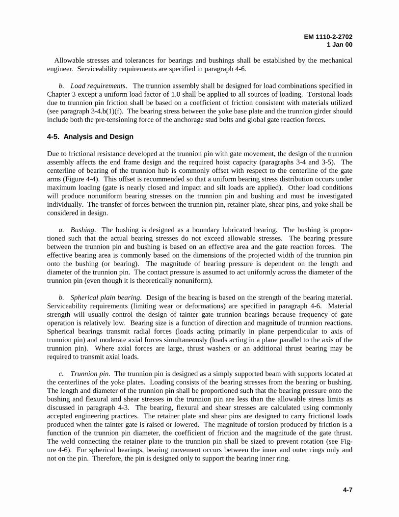
EM 1110-2-27021 Jan 00
4-7
Allowable stresses and tolerances for bearings and bushings shall be established by the mechanicalengineer. Serviceability requirements are specified in paragraph 4-6.
b. Load requirements. The trunnion assembly shall be designed for load combinations specified inChapter 3 except a uniform load factor of 1.0 shall be applied to all sources of loading. Torsional loadsdue to trunnion pin friction shall be based on a coefficient of friction consistent with materials utilized(see paragraph 3-4.b(1)(f). The bearing stress between the yoke base plate and the trunnion girder shouldinclude both the pre-tensioning force of the anchorage stud bolts and global gate reaction forces.
4-5. Analysis and Design
Due to frictional resistance developed at the trunnion pin with gate movement, the design of the trunnionassembly affects the end frame design and the required hoist capacity (paragraphs 3-4 and 3-5). Thecenterline of bearing of the trunnion hub is commonly offset with respect to the centerline of the gatearms (Figure 4-4). This offset is recommended so that a uniform bearing stress distribution occurs undermaximum loading (gate is nearly closed and impact and silt loads are applied). Other load conditionswill produce nonuniform bearing stresses on the trunnion pin and bushing and must be investigatedindividually. The transfer of forces between the trunnion pin, retainer plate, shear pins, and yoke shall beconsidered in design.
a. Bushing. The bushing is designed as a boundary lubricated bearing. The bushing is propor-tioned such that the actual bearing stresses do not exceed allowable stresses. The bearing pressurebetween the trunnion pin and bushing is based on an effective area and the gate reaction forces. Theeffective bearing area is commonly based on the dimensions of the projected width of the trunnion pinonto the bushing (or bearing). The magnitude of bearing pressure is dependent on the length anddiameter of the trunnion pin. The contact pressure is assumed to act uniformly across the diameter of thetrunnion pin (even though it is theoretically nonuniform).
b. Spherical plain bearing. Design of the bearing is based on the strength of the bearing material.Serviceability requirements (limiting wear or deformations) are specified in paragraph 4-6. Materialstrength will usually control the design of tainter gate trunnion bearings because frequency of gateoperation is relatively low. Bearing size is a function of direction and magnitude of trunnion reactions.Spherical bearings transmit radial forces (loads acting primarily in plane perpendicular to axis oftrunnion pin) and moderate axial forces simultaneously (loads acting in a plane parallel to the axis of thetrunnion pin). Where axial forces are large, thrust washers or an additional thrust bearing may berequired to transmit axial loads.
c. Trunnion pin. The trunnion pin is designed as a simply supported beam with supports located atthe centerlines of the yoke plates. Loading consists of the bearing stresses from the bearing or bushing.The length and diameter of the trunnion pin shall be proportioned such that the bearing pressure onto thebushing and flexural and shear stresses in the trunnion pin are less than the allowable stress limits asdiscussed in paragraph 4-3. The bearing, flexural and shear stresses are calculated using commonlyaccepted engineering practices. The retainer plate and shear pins are designed to carry frictional loadsproduced when the tainter gate is raised or lowered. The magnitude of torsion produced by friction is afunction of the trunnion pin diameter, the coefficient of friction and the magnitude of the gate thrust.The weld connecting the retainer plate to the trunnion pin shall be sized to prevent rotation (see Fig-ure 4-6). For spherical bearings, bearing movement occurs between the inner and outer rings only andnot on the pin. Therefore, the pin is designed only to support the bearing inner ring.
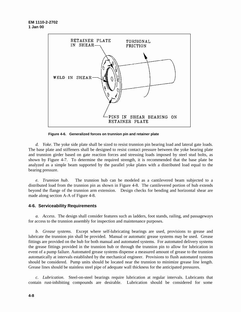
EM 1110-2-27021 Jan 00
4-8
d. Yoke. The yoke side plate shall be sized to resist trunnion pin bearing load and lateral gate loads.The base plate and stiffeners shall be designed to resist contact pressure between the yoke bearing plateand trunnion girder based on gate reaction forces and stressing loads imposed by steel stud bolts, asshown by Figure 4-7. To determine the required strength, it is recommended that the base plate beanalyzed as a simple beam supported by the parallel yoke plates with a distributed load equal to thebearing pressure.
e. Trunnion hub. The trunnion hub can be modeled as a cantilevered beam subjected to adistributed load from the trunnion pin as shown in Figure 4-8. The cantilevered portion of hub extendsbeyond the flange of the trunnion arm extension. Design checks for bending and horizontal shear aremade along section A-A of Figure 4-8.
4-6. Serviceability Requirements
a. Access. The design shall consider features such as ladders, foot stands, railing, and passagewaysfor access to the trunnion assembly for inspection and maintenance purposes.
b. Grease systems. Except where self-lubricating bearings are used, provisions to grease andlubricate the trunnion pin shall be provided. Manual or automatic grease systems may be used. Greasefittings are provided on the hub for both manual and automated systems. For automated delivery systemsthe grease fittings provided in the trunnion hub or through the trunnion pin to allow for lubrication inevent of a pump failure. Automated grease systems dispense a measured amount of grease to the trunnionautomatically at intervals established by the mechanical engineer. Provisions to flush automated systemsshould be considered. Pump units should be located near the trunnion to minimize grease line length.Grease lines should be stainless steel pipe of adequate wall thickness for the anticipated pressures.
c. Lubrication. Steel-on-steel bearings require lubrication at regular intervals. Lubricants thatcontain rust-inhibiting compounds are desirable. Lubrication should be considered for some
Figure 4-6. Generalized forces on trunnion pin and retainer plate
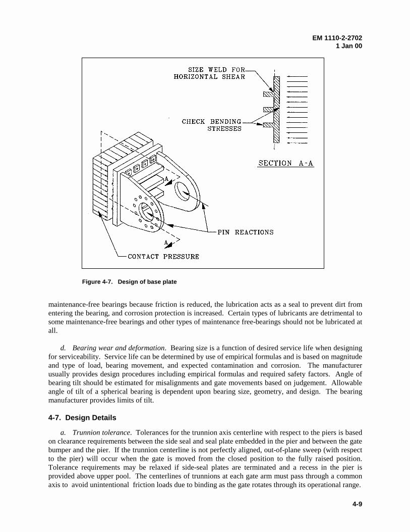
EM 1110-2-27021 Jan 00
4-9
maintenance-free bearings because friction is reduced, the lubrication acts as a seal to prevent dirt fromentering the bearing, and corrosion protection is increased. Certain types of lubricants are detrimental tosome maintenance-free bearings and other types of maintenance free-bearings should not be lubricated atall.
d. Bearing wear and deformation. Bearing size is a function of desired service life when designingfor serviceability. Service life can be determined by use of empirical formulas and is based on magnitudeand type of load, bearing movement, and expected contamination and corrosion. The manufacturerusually provides design procedures including empirical formulas and required safety factors. Angle ofbearing tilt should be estimated for misalignments and gate movements based on judgement. Allowableangle of tilt of a spherical bearing is dependent upon bearing size, geometry, and design. The bearingmanufacturer provides limits of tilt.
4-7. Design Details
a. Trunnion tolerance. Tolerances for the trunnion axis centerline with respect to the piers is basedon clearance requirements between the side seal and seal plate embedded in the pier and between the gatebumper and the pier. If the trunnion centerline is not perfectly aligned, out-of-plane sweep (with respectto the pier) will occur when the gate is moved from the closed position to the fully raised position.Tolerance requirements may be relaxed if side-seal plates are terminated and a recess in the pier isprovided above upper pool. The centerlines of trunnions at each gate arm must pass through a commonaxis to avoid unintentional friction loads due to binding as the gate rotates through its operational range.
Figure 4-7. Design of base plate
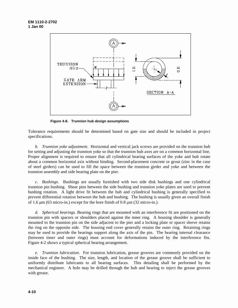
EM 1110-2-27021 Jan 00
4-10
Tolerance requirements should be determined based on gate size and should be included in projectspecifications.
b. Trunnion yoke adjustment. Horizontal and vertical jack screws are provided on the trunnion hubfor setting and adjusting the trunnion yoke so that the trunnion hub axes are on a common horizontal line.Proper alignment is required to ensure that all cylindrical bearing surfaces of the yoke and hub rotateabout a common horizontal axis without binding. Second-placement concrete or grout (zinc in the caseof steel girders) can be used to fill the space between the trunnion girder and yoke and between thetrunnion assembly and side bearing plate on the pier.
c. Bushings. Bushings are usually furnished with two side disk bushings and one cylindricaltrunnion pin bushing. Shear pins between the side bushing and trunnion yoke plates are used to preventbushing rotation. A light drive fit between the hub and cylindrical bushing is generally specified toprevent differential rotation between the hub and bushing. The bushing is usually given an overall finishof 1.6 Pm (63 micro-in.) except for the bore finish of 0.8 Pm (32 micro-in.).
d. Spherical bearings. Bearing rings that are mounted with an interference fit are positioned on thetrunnion pin with spacers or shoulders placed against the inner ring. A housing shoulder is generallymounted to the trunnion pin on the side adjacent to the pier and a locking plate or spacer sleeve retainsthe ring on the opposite side. The housing end cover generally retains the outer ring. Retaining ringsmay be used to provide the bearings support along the axis of the pin. The bearing internal clearance(between inner and outer rings) must account for deformations induced by the interference fits.Figure 4-2 shows a typical spherical bearing arrangement.
e. Trunnion lubrication. For trunnion lubrication, grease grooves are commonly provided on theinside face of the bushing. The size, length, and location of the grease groove shall be sufficient touniformly distribute lubricants to all bearing surfaces. This detailing shall be performed by themechanical engineer. A hole may be drilled through the hub and bearing to inject the grease grooveswith grease.
Figure 4-8. Trunnion hub design assumptions

EM 1110-2-27021 Jan 00
4-11
f. Trunnion pin. Trunnion pins may be designed with a hole drilled along the pin centerline forentry of a radioactive source to facilitate radiographic testing. The hole may also be tapped for handling,installation, and removal purposes.
EM 1110-2-27021 Jan 00
5-1
Chapter 5Gate Anchorage Systems
5-1. General Description
The trunnion girder is held in place by an anchorage system that extends into the concrete pier.Anchorage systems can be classified as prestressed or nonprestressed. The prestressed system includeshigh strength, preloaded components while the nonprestressed system incorporates structural steelcomponents. A general arrangement of a gate anchorage system is shown in Figure 5-1.
a. Prestressed systems. Prestressed systems consist of groups of posttensioned members that anchorthe trunnion girder to the pier. The posttensioning operation creates an initial compressive stress in thesystem that acts to maintain trunnion girder-to-pier contact and to reduce structural cracks in the pierconcrete. Figure 5-2 describes a typical posttensioned anchorage system. The anchors are placed insideducts embedded in the concrete and are tensioned after concrete has set and cured. Subsequent totensioning, the annular space between the posttensioning steel and duct is grouted for corrosionprotection. Generally, two groups of anchorage steel are installed, one near each pier face. A limitedbearing area is provided directly under each anchorage group. A compressible material is placed betweenthe anchorage bearing areas at the trunnion girder-to-pier interface to intentionally prevent the transfer ofstress across this reach. This detail enhances structural performance by reducing negative bendingmoments in the trunnion girder, and a larger moment arm between anchorage groups is available to resistnonsymmetrical loads. Alternate anchorage systems are shown by Figure 5-3. These systems arecomprised of additional plates or other structural members anchored into pier concrete and connected tothe trunnion girder (e.g., embedded plates or separate structural members anchored to pier and connectedto the trunnion girder). Loads are transmitted from the trunnion girder to the anchorage system throughthese additional members, creating a larger area of pier concrete to resist posttensioning forces and loadsapplied to the trunnion girder. Therefore, concrete stresses will be lower, and bursting and spallingreinforcement is reduced. Additional connections and components are required for these systems.
b. Nonprestressed systems. Nonprestressed systems may consist of embedded standard shapes,large-diameter rods or built-up sections. Nonprestressed systems are relatively easy to design and install.However, nonprestressed systems allow greater deflections of the trunnion girder, allow tension andpossibly structural cracking in concrete (bonded anchors), and require a large cross-sectional area of steel.This type of anchorage system is not recommended except for projects with small tainter gates. This EMprovides criteria only for prestressed systems. 5-2. Components
A complete posttensioned anchorage system includes tendons (bars or strands), anchorage devices orbearing plates, ducts, end caps, grout tubes, couplers, anchorage zones, and a corrosion protection system.Anchorage zones include a portion of pier in the vicinity of tendon anchorage at either end of the tendons.The anchorage zone is geometrically defined as the volume of concrete through which the concentratedtendon force applied at an anchorage device (or girder-to-pier bearing area) dissipates to an area of morelinear stress distribution throughout a cross section some distance from the anchorage device.
a. Tendons and anchorage. Tendons can be high-strength, low-alloy steel bars or strands. Thetendons are posttensioned at the trunnion girder (referred to as the live end) to hold the trunnion girder tothe pier. They pass through the trunnion girder and terminate at embedded bearing plates or anchoragedevices (referred to as the dead end) within the pier. The embedded length of the tendons is typically 9 to
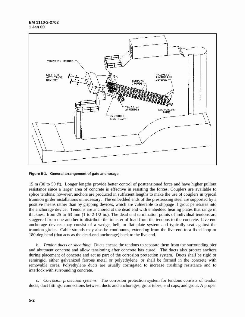
EM 1110-2-27021 Jan 00
5-2
15 m (30 to 50 ft). Longer lengths provide better control of posttensioned force and have higher pulloutresistance since a larger area of concrete is effective in resisting the forces. Couplers are available tosplice tendons; however, anchors are produced in sufficient lengths to make the use of couplers in typicaltrunnion girder installations unnecessary. The embedded ends of the prestressing steel are supported by apositive means rather than by gripping devices, which are vulnerable to slippage if grout penetrates intothe anchorage device. Tendons are anchored at the dead end with embedded bearing plates that range inthickness from 25 to 63 mm (1 to 2-1/2 in.). The dead-end termination points of individual tendons arestaggered from one another to distribute the transfer of load from the tendons to the concrete. Live-endanchorage devices may consist of a wedge, bell, or flat plate system and typically seat against thetrunnion girder. Cable strands may also be continuous, extending from the live end to a fixed loop or180-deg bend (that acts as the dead-end anchorage) back to the live end.
b. Tendon ducts or sheathing. Ducts encase the tendons to separate them from the surrounding pierand abutment concrete and allow tensioning after concrete has cured. The ducts also protect anchorsduring placement of concrete and act as part of the corrosion protection system. Ducts shall be rigid orsemirigid, either galvanized ferrous metal or polyethylene, or shall be formed in the concrete withremovable cores. Polyethylene ducts are usually corrugated to increase crushing resistance and tointerlock with surrounding concrete.
c. Corrosion protection systems. The corrosion protection system for tendons consists of tendonducts, duct fittings, connections between ducts and anchorages, grout tubes, end caps, and grout. A proper
Figure 5-1. General arrangement of gate anchorage
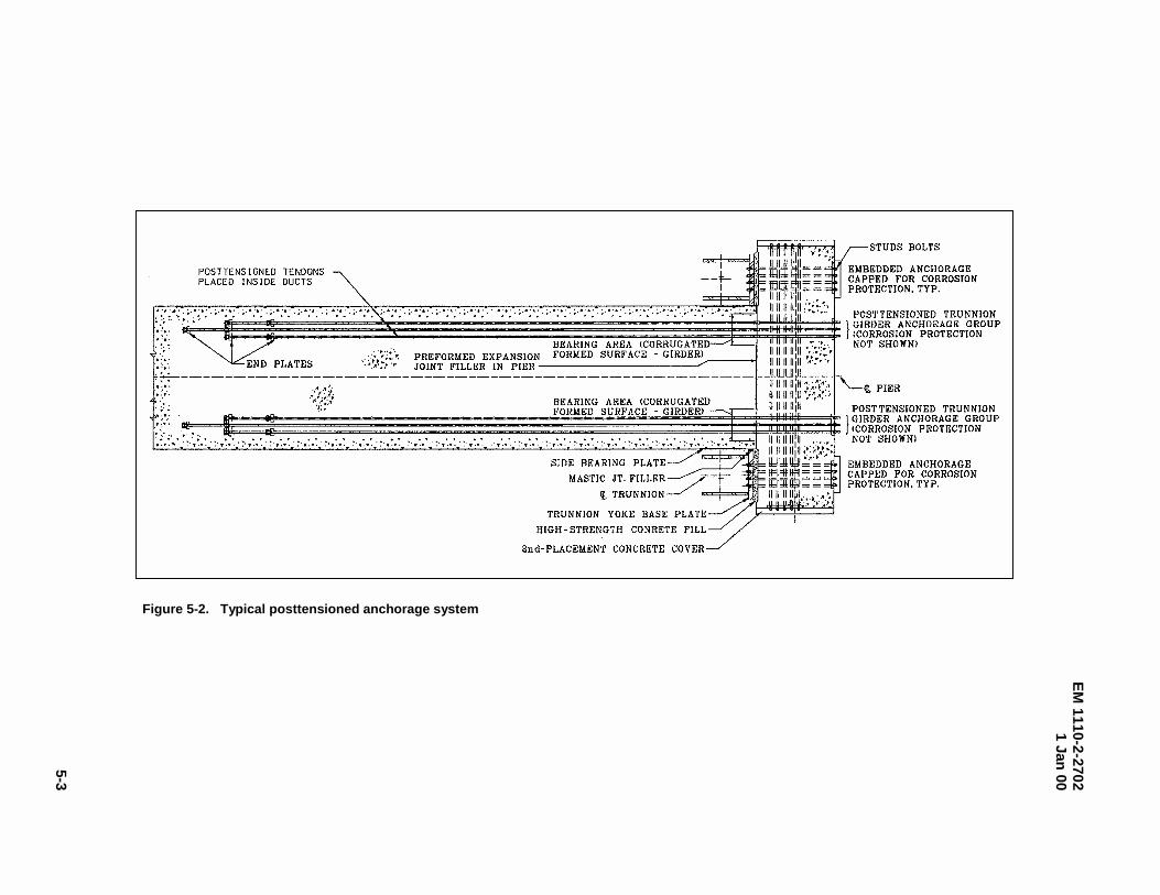
EM
1110-2-27021 Jan
00
5-3
Figure 5-2. Typical posttensioned anchorage system
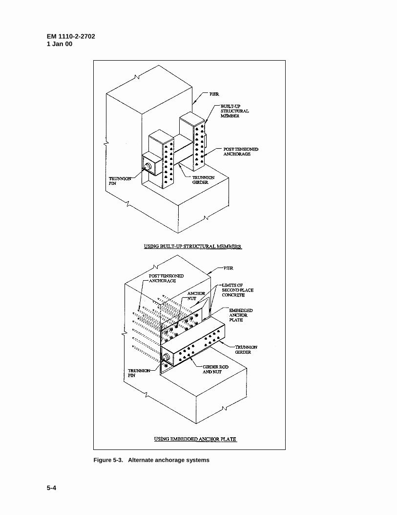
EM 1110-2-27021 Jan 00
5-4
Figure 5-3. Alternate anchorage systems
EM 1110-2-27021 Jan 00
5-5
duct system will prevent infiltration of moisture into the duct. Special fittings are provided for ductsplices and connections between ducts and anchor plates using threaded or slip connectors and areprovided with seals to prevent infiltration at these locations. Grout tubes extend from the sheathing toallow access for grouting. End caps are placed over the live end of the anchors and anchor nuts or wedgesafter stressing is complete and excess tendon removed. The grout encapsulates the tendon to preventcorrosion. Additional information on ducts can be found in Article 10.8.2, AASHTO LRFD BridgeConstruction Specifications (AASHTO 1994).
5-3. Material Selection
a. Pier concrete. The minimum compressive strength of concrete in anchorage zones shall be30 MPa (4500 psi). The minimum compressive strength of concrete between the anchorage zones shall be28 MPa (4000 psi). Higher concrete strengths may be considered if required; however, specificationsshould include requirements on material controls and fabrication procedures to ensure the requiredstrength. The maximum concrete aggregate size should be selected to pass between reinforcing bars.
b. Tendons. Posttensioning bars shall be of high-tensile alloy steel, conforming to the requirementsof ASTM Designation A722. Cable strands shall conform to ASTM A416 with a minimum strength of1860 MPa (270 ksi).
c. Steel for pier reinforcement. Reinforcing steel shall be deformed bars conforming to ASTMA615, ASTM A616 including Supplementary Requirement S1, ASTM A617, or ASTM A706. Thespecified yield strength shall be 400 Mpa (60 ksi). ASTM A706 shall be specified when bars are weldedto form a cage.
d. Ducts. Galvanized steel pipe ducts shall conform to ASTM A53. Additional information onducts can be found in Article 10.8.2, AASHTO LRFD Bridge Construction Specifications (AASHTO1994).
5-4. Design Requirements
A properly designed anchor system will prevent structural cracking of concrete, limit deflections, accountfor all time-dependent stress losses, and safely accommodate specified loads for the life of the structure.Objectionable deflections and structural cracking may occur if the trunnion girder looses contact with thepier (lift-off). Lift-off can be controlled by an effective anchorage force that maintains residualcompressive stresses between the trunnion girder and pier. The design of the gate anchorage system isbased on strength and service limit states. The strength limit states ensure that the anchorage system willresist all factored loading combinations without failing. Service limit states are provided to restrictstresses, deformations, and cracks that adversely affect performance under typical or normal loadingconditions at specified stages of use.
a. Design basis. Except as modified herein, the posttensioned anchorage system shall be designed inaccordance with AASHTO (1994). The system shall be proportioned such that the limit states as specifiedin paragraph 5-4.c are not exceeded when the system is subject to loads as specified in paragraph 5-4.b.In general, the amount of anchorage steel required will be controlled by service limit states. Anchoragegroups shall be sized such that the long-term effective anchorage force provides a minimum specifiedcompressive stress between the girder and pier while the system is subject to the maximum trunnionreaction due to service loads. Additionally, the anchorage group shall have an ultimate strength greaterthan that required for factored loads. The anchorage zones, including spalling, bursting, and edge tensionreinforcement shall be designed following procedures described by AASHTO (1994), Section 5.10.9,using factored jacking forces as specified in paragraph 5-4.b(1). The initial jacking force is based on the
EM 1110-2-27021 Jan 00
5-6
required long-term effective stress and includes all prestress losses (paragraph 5-5.h). A recommendedanalytical model to determine anchorage forces is described in paragraph 5-5.b.
b. Load requirements. The anchor system shall be designed to resist loads as follows. In general,the maximum load will occur when one gate is raised just off the sill and the adjacent gate (if applicable)is unloaded.
(1) Strength limit state. Load cases shall be as specified in paragraph 3-4, except that a uniform loadfactor of 1.9 shall be applied to each of the applied loads for the design of tendons. The anchorage zoneshall be designed for the jacking load only using a load factor of 1.2.
(2) Service limit state. Load combinations shall be as specified in paragraph 3-4, except that auniform load factor of 1.0 shall be applied to each of the applied loads.
c. Limit states. Limit states are identified for tendons, anchorage zone reinforcement, girder-to-pierbearing, and pier concrete.
(1) Strength limit state. The strength limit of the tendons shall be as specified AASHTO (1994),Section 5.9.3, and the resistance factor I shall be 1.0. The strength limit of the pier concrete shall basedon the criteria for an eccentrically loaded tension member as specified in AASHTO (1994),Section 5.7.6.2, and the resistance factor I shall be 0.9. Resistance factors for the design of anchoragezones shall be as specified in AASHTO (1994), Section 5.5.4.
(2) Service limit state. The service limit states are intended to limit tendon and pier concrete stressesat three stages including jacking (tendons only), after transfer of jacking loads and before losses, and afterlosses with trunnion service loads. Tendon stresses shall be limited to those values provided in Sec-tion 5.9.3, AASHTO (1994). The tendons shall be sized to maintain a minimum compressive bearingstress between the girder and the pier of 1.4 MPa (200 psi). For pier concrete, stresses shall be limited inaccordance with Section 5.9.4, AASHTO (1994), except that tension stresses are not allowed.
5-5. Analysis and Design Considerations
a. Primary axis orientation. The orientation of the tendons (or primary axis) of the gate anchoragesystem is usually set to coincide with line of action of the maximum trunnion reaction based on serviceloads. The maximum gate reaction usually occurs with unsymmetrical hoist support conditions.
b. Analytical model for anchorage forces. The trunnion girder is assumed to behave as a simplysupported beam with cantilevered end spans as shown in Figure 5-4. The gate anchorage represents thesimple supports. The position of support is assumed to lie at the center of gravity of the anchorage steelgroup. Reaction forces are determined by summing moments about the supports. The anchorage force isequal to the calculated reaction Rmax.
c. Analytical model for anchorage zones. Analysis for the design of anchorage zones may includestrut and tie models, elastic stress analysis or other approximate methods. These methods are described inSection 5.10.9 of AASHTO (1994).
d. Girder-to-pier bearing stresses. Compressive bearing stresses exist along the contact areabetween the girder and the pier due the posttensioning operation. Time-dependent losses and external
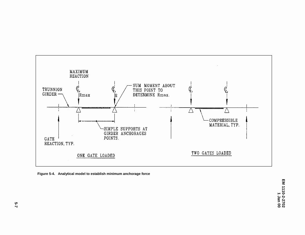
EM
1110-2-27021 Jan
00
5-7
Figure 5-4. Analytical model to establish minimum anchorage force
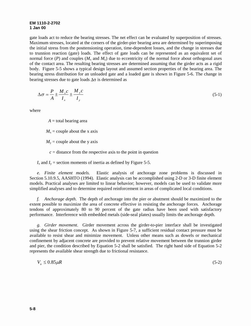
EM 1110-2-27021 Jan 00
5-8
gate loads act to reduce the bearing stresses. The net effect can be evaluated by superposition of stresses.Maximum stresses, located at the corners of the girder-pier bearing area are determined by superimposingthe initial stress from the posttensioning operation, time-dependent losses, and the change in stresses dueto trunnion reaction (gate) loads. The effect of gate loads can be represented as an equivalent set ofnormal force (P) and couples (Mx and My) due to eccentricity of the normal force about orthogonal axesof the contact area. The resulting bearing stresses are determined assuming that the girder acts as a rigidbody. Figure 5-5 shows a typical design layout and assumed section properties of the bearing area. Thebearing stress distribution for an unloaded gate and a loaded gate is shown in Figure 5-6. The change inbearing stresses due to gate loads 'V is determined as
y
y
x
x
I
cM
I
cM
A
P����� (5-1)
where
A = total bearing area
Mx = couple about the x axis
My = couple about the y axis
c = distance from the respective axis to the point in question
Ix and Iy = section moments of inertia as defined by Figure 5-5.
e. Finite element models. Elastic analysis of anchorage zone problems is discussed inSection 5.10.9.5, AASHTO (1994). Elastic analysis can be accomplished using 2-D or 3-D finite elementmodels. Practical analyses are limited to linear behavior; however, models can be used to validate moresimplified analyses and to determine required reinforcement in areas of complicated local conditions.
f. Anchorage depth. The depth of anchorage into the pier or abutment should be maximized to theextent possible to maximize the area of concrete effective in resisting the anchorage forces. Anchoragetendons of approximately 80 to 90 percent of the gate radius have been used with satisfactoryperformance. Interference with embedded metals (side-seal plates) usually limits the anchorage depth.
g. Girder movement. Girder movement across the girder-to-pier interface shall be investigatedusing the shear friction concept. As shown in Figure 5-7, a sufficient residual contact pressure must beavailable to resist shear and minimize movement. Unless other means such as dowels or mechanicalconfinement by adjacent concrete are provided to prevent relative movement between the trunnion girderand pier, the condition described by Equation 5-2 shall be satisfied. The right hand side of Equation 5-2represents the available shear strength due to frictional resistance.
RVu �85.0� (5-2)
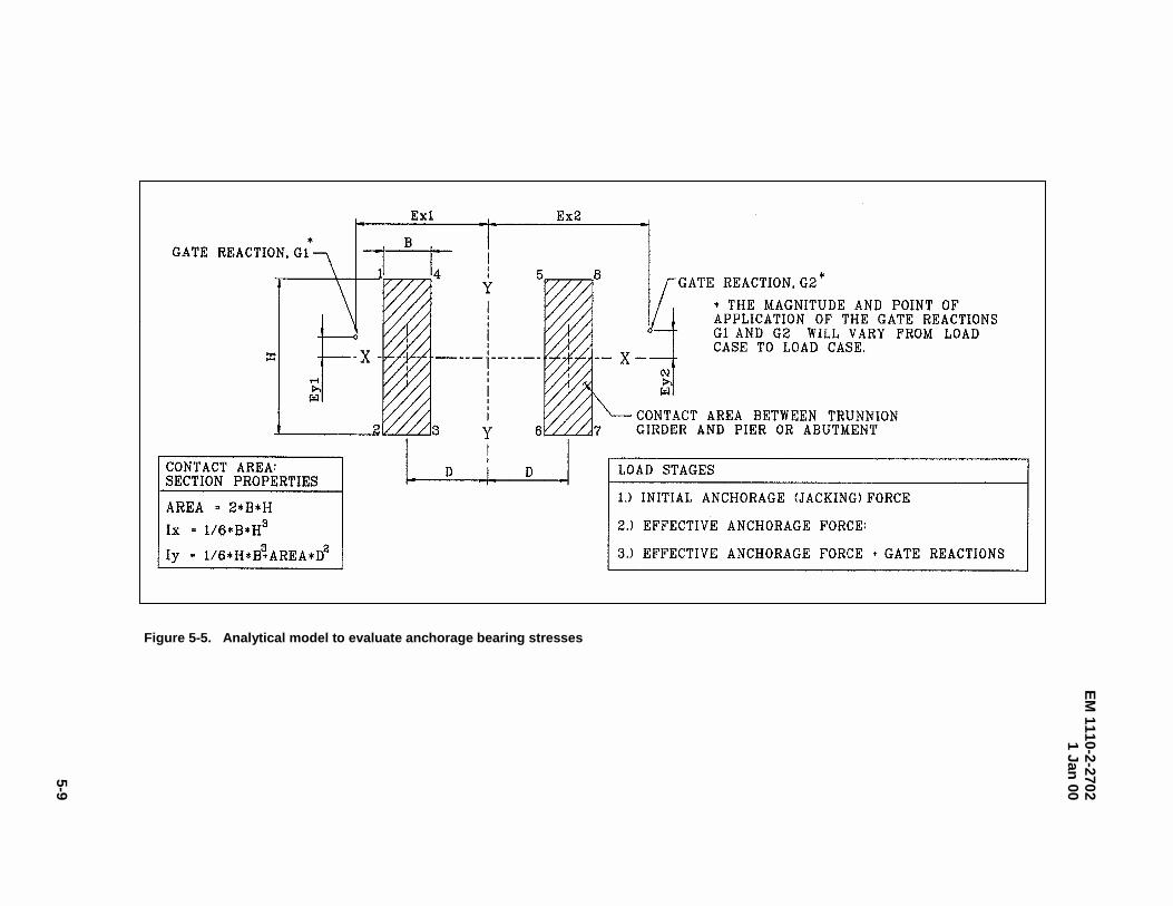
EM
1110-2-27021 Jan
00
5-9
Figure 5-5. Analytical model to evaluate anchorage bearing stresses
EM 1110-2-27021 Jan 00
5-10
where
Vu = factored shear force
P = coefficient of friction for the interface
R = residual compressive force between the girder and pier
h. Effective stresses. Estimated lump-sum losses (assumed values not supported by computation)may be used for the initial design of prestressed concrete. However, the final design should account forindividual losses due to elastic shortening, shrinkage, concrete creep, steel relaxation, anchorage set, andfriction. For straight tendons, losses due to friction may be neglected. The value of anchor set loss can beassumed or obtained from the manufacturer and should be verified prior to construction. A more refinedincremental time-step analysis of losses is typically not required. AASHTO (1994), Section 5.9.5,provides guidance for estimating prestress losses.
i. Anchorage zone reinforcement. A portion of pier concrete adjacent to the trunnion girder andanchor plates will be subject to tensile stresses. Tension exists in a portion of concrete located at thecenter of the anchorage tendons (bars) ahead of the anchorage device or girder. This area is termed thebursting zone. At the end of the pier adjacent to the girder, edge tension forces may exist along the sidesand end surface. The edge tension forces along the end surface are referred to as spalling forces.Reinforcement shall be provided where required in the tendon anchorage zones to resist bursting and edgetension forces induced by tendon anchorages. Design guidance regarding bursting, spalling and edgetension is specified by AASHTO (1994), Section 5.10.9.3.
5-6. Serviceability
Corrosion of the tendons and anchorage components is the primary serviceability concern regardingdesign of the anchorage system. Corrosion of tendons must be avoided because it can lead to potentialfailure of the tendons and because the tendons are difficult to replace. The anchorage system shall bedoubly protected against corrosion. With a properly constructed system, the tendons are doubly protectedagainst corrosion since ducts and grout both prevent moisture penetration.
a. Duct and grout requirements. To eliminate the penetration of moisture or other corrosivesubstances, the duct system (including sheathing and all connections) shall be water or gas tight. Ductsshall be nonreactive with concrete, tendons, and grout. Ducts shall have an inside diameter at least 6 mm
Figure 5-6. Stress distributions between pier/trunnion girder interface
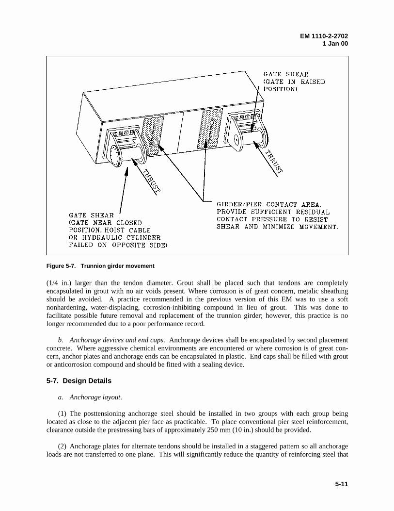
EM 1110-2-27021 Jan 00
5-11
(1/4 in.) larger than the tendon diameter. Grout shall be placed such that tendons are completelyencapsulated in grout with no air voids present. Where corrosion is of great concern, metalic sheathingshould be avoided. A practice recommended in the previous version of this EM was to use a softnonhardening, water-displacing, corrosion-inhibiting compound in lieu of grout. This was done tofacilitate possible future removal and replacement of the trunnion girder; however, this practice is nolonger recommended due to a poor performance record.
b. Anchorage devices and end caps. Anchorage devices shall be encapsulated by second placementconcrete. Where aggressive chemical environments are encountered or where corrosion is of great con-cern, anchor plates and anchorage ends can be encapsulated in plastic. End caps shall be filled with groutor anticorrosion compound and should be fitted with a sealing device.
5-7. Design Details
a. Anchorage layout.
(1) The posttensioning anchorage steel should be installed in two groups with each group beinglocated as close to the adjacent pier face as practicable. To place conventional pier steel reinforcement,clearance outside the prestressing bars of approximately 250 mm (10 in.) should be provided.
(2) Anchorage plates for alternate tendons should be installed in a staggered pattern so all anchorageloads are not transferred to one plane. This will significantly reduce the quantity of reinforcing steel that
Figure 5-7. Trunnion girder movement
EM 1110-2-27021 Jan 00
5-12
would otherwise be required to control vertical tension cracks in the concrete. A staggered spacing of 0.6to 1.2 m (2 to 4 ft) has been used successfully in the past to distribute anchorage forces.
b. Reinforcement considerations.
(1) Anchorage zones. Spalling zone reinforcement that consists of conventional grid reinforcementdesigned to resist approximately 4 percent of the total prestressing force will be adequate for most cases.The reinforcement should be placed as near to the surface as practicable. For typical arrangements, tensilestresses in the bursting zone have been shown to be a maximum of about 18 percent of the unitcompression stress due to the longitudinal prestressing. Reinforcement for these stresses should beprovided from the downstream pier face into the pier for a distance of approximately one-half the widthof the pier.
(2) Pier corners. To prevent spalling of the concrete at the corners of the pier, it is suggested that theouter layer of reinforcement be welded to angles that are embedded along the vertical edges of the pier.
c. Construction considerations.
(1) To minimize integral action between the girder and the pier during posttensioning, all contactsurfaces between the girder and the pier (except structural bearing zones) should be troweled smooth orseparated by a premolded expansion joint material.
(2) Tendons can be placed horizontally if the gate trunnion is oriented so that the vertical componentof thrust is negligible. With horizontal tendons, fewer lifts of anchorage zone concrete are required andconstruction is simplified.
(3) Pier prestressing tendons should be installed prior to installation of conventional reinforcementand forms. This will permit close inspection of the embedded ends to ensure proper construction.
EM 1110-2-27021 Jan 00
6-1
Chapter 6Trunnion Girder
6-1. General Description
The trunnion girder supports the tainter gate. The trunnion girder and associated anchorage are criticalitems since all loads acting on the gate are transferred from the trunnion through the girder and anchorageto the piers. The girders are located on the downstream pier face and are held in place by a prestressed ornonprestressed anchorage system that extends into the pier (Chapter 5.). Trunnion girders can beconstructed of posttensioned concrete or steel. Selection of girder type (steel or posttensioned concrete)is dependent upon a variety of factors including availability of quality fabricators or precasters, siteexposure conditions, economics, and designer preference. Posttensioned concrete trunnion girders arevery stiff resulting in minimal deflections and offer significant resistance to torsional and impact loads.Steel girders are susceptible to corrosion and are more flexible than concrete girders but are more easilyretrofitted and repaired. Due to their higher flexibility, steel girders are intended for use with smallergates. Paragraph 6-6.c provides guidance on use of steel girders.
6-2. Components
a. Posttensioned concrete. A concrete trunnion girder may be of precast or cast-in-placeconstruction. In either construction method, the girder is posttensioned longitudinally to controlin-service deflections. (Posttensioning also increases girder resistance to flexure, shear, and torsion.)Longitudinal ducts are provided for the posttensioning tendons and recesses are commonly provided forsecond placement concrete pours between the trunnion assembly and pier. Conventional reinforcement isprovided to resist shear, torsion, bursting, and reverse loading forces, and to control spalling. Figure 6-1shows the upstream face of a typical concrete trunnion girder.
b. Structural steel. Steel trunnion girders are typically of welded construction and are I-shaped orbox-shaped. I-shaped members can be made from plates or standard steel sections and are primarily usedwhere torsion is not a significant concern. Box-shaped girders are fabricated from standard sections orplate steel and are much more efficient in resisting torsional loads. Box-shaped girders (especially thosethat include center-mounted pins) are more difficult to fabricate, coat, and inspect than I-shape girders.(Paragraph 4-1.b describes center-mounted pins.) Girder stiffeners are used to increase web stability inareas of high shear and where posttension anchorage forces are applied. Stiffeners also increase torsionalstiffness and provide support for center-mounted pins. Figure 6-2 depicts a typical steel girderconfiguration.
6-3. Material Selection
a. Concrete girders. The minimum compressive strength of concrete shall be 33MPa (5000 psi).Higher concrete strengths may be considered; however, specifications should include requirements onmaterial controls and fabrication procedures to ensure the required strength.
b. Prestressing reinforcement for concrete girders. The posttensioning bars shall be of high-tensilealloy steel, conforming to the requirements of ASTM Designation A722. Posttensioning strands shall below-relaxation, high-tensile, seven-wire strands conforming to ASTM A416 with a minimum strength of1860 MPa (270 ksi). Bars are generally preferred over strands because they are less susceptible to stresscorrosion.
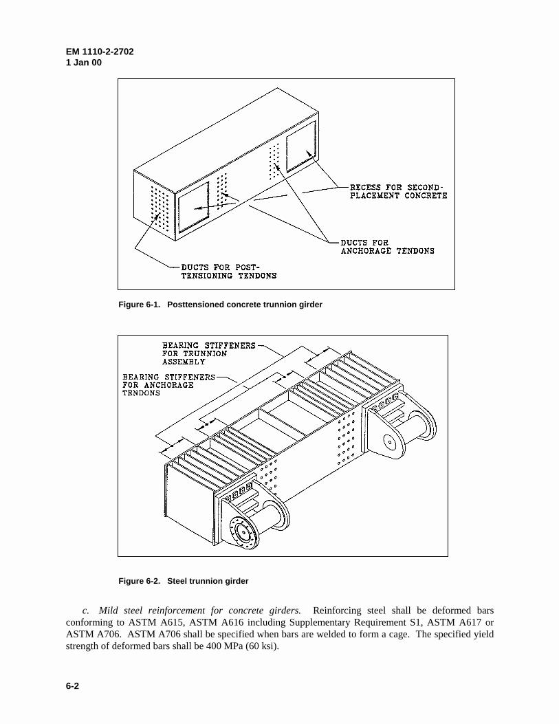
EM 1110-2-27021 Jan 00
6-2
c. Mild steel reinforcement for concrete girders. Reinforcing steel shall be deformed barsconforming to ASTM A615, ASTM A616 including Supplementary Requirement S1, ASTM A617 orASTM A706. ASTM A706 shall be specified when bars are welded to form a cage. The specified yieldstrength of deformed bars shall be 400 MPa (60 ksi).
Figure 6-1. Posttensioned concrete trunnion girder
Figure 6-2. Steel trunnion girder
EM 1110-2-27021 Jan 00
6-3
d. Steel girder. Steel trunnion girders are considered fracture critical members (paragraph 3-8).Either ASTM A36 or ASTM A572 can be specified.
6-4. Design Requirements
Trunnion girders shall have sufficient strength to withstand combined forces of bending, torsion, shear,and axial compression due to trunnion reaction and anchorage forces. Girder torsion that occurs due totrunnion pin friction (as the gate is operated) and eccentric loads applied at the trunnion pin shall beconsidered. However, torsion due to trunnion pin friction shall not be considered if it counteracts torsionresulting from other loads. The design load cases shall be consistent with the operational range of thegate (i.e., consider loading from closed to open positions and intermediate positions). For multigateprojects, the orientation of adjacent gates shall be considered (i.e., one gate closed, other gate open orclosed or dewatered for maintenance) when evaluating the loading condition on the trunnion girder.Specific requirements for concrete and steel girders are provided in paragraphs 6-4a and b, respectively.
a. Concrete girders.
(1) Design basis. Concrete trunnion girders shall be designed based on the strength design methodin accordance with ACI (1995), except as modified herein. Behavior under service loads shall beconsidered at all load stages that may be critical during the life of the project from the timeposttensioning is first applied. The posttensioned anchorage zones shall be designed and detailed inaccordance with AASHTO (1994), Section 5.10.9.
(2) Load requirements. The required strength of concrete trunnion girders shall be determined inaccordance with the load combinations specified in paragraph 3-4.b, except the following load factorsshall be used. A uniform load factor of 1.7 shall be applied to each of the specified loads for evaluatingstrength limit states and a load factor equal to 1.0 shall be applied to each of the loads for evaluatingservice limit states. A load factor of 1.2 shall be applied to the girder anchorage force.
(3) Limit states.
(a) Strength limit state. The design strength (nominal strength multiplied by a strength reductionfactor) shall be greater than the required strength. The nominal strength and strength reduction factorsshall be determined in accordance with ACI (1995).
(b) Service limit state. Service limit states are provided to limit tendon and concrete stresses atvarious stages including jacking (tendons only), after prestress transfer but before time dependentprestress losses, and after prestress losses have occurred (concrete only). These stages and prestresslosses are discussed in Sections 18.4, 18.5 and 18.6, ACI (1995). Tendon stresses shall not exceed thosespecified in Section 18.5 of ACI (1995). Concrete stresses shall not exceed those provided in Table 6-1.The compressive strength of concrete at the time of initial prestress is denoted fcci, and fcc is the specifiedcompressive strength of concrete.
Table 6-1Service Limit State Concrete Stresses
Stress immediately after prestress transfer beforeprestress losses due to creep and shrinkage
Stress at service load after allowance forall prestress losses
Compression 0.55 fcci 0.4 fcc
Tension 0.0 0.0
EM 1110-2-27021 Jan 00
6-4
b. Structural steel.
(1) Design basis. Steel trunnion girders shall be proportioned and designed in accordance withparagraph 3-4 and EM 1110-2-2105.
(2) Load requirements. Steel trunnion girders shall be designed to resist trunnion loads due to loadcombinations specified in paragraph 3-4.b. A load factor equal to 1.2 shall be applied to the girderanchorage force.
(3) Limit states. Strength and serviceability limit states shall be considered in the design of steeltrunnion girders.
(a) The strength limit states of yielding and buckling shall be evaluated in accordance with AISC(1994), Chapter H (for members under combined torsion, flexure, shear and axial forces), modified asrequired by paragraph 3-4.c. Resolved normal and shear stresses due to factored loads (i.e., requiredstrength) shall not exceed the factored yield strength (i.e., design strength), and normal stresses due tofactored loads (required strength) shall not exceed the factored critical buckling stress (design strength)of the member. When shear and normal stresses are of comparable magnitude, the affect of combinedstresses can be evaluated by Von Mises stresses. The Von Mises stresses due to factored loads shouldnot exceed the factored yield strength using I = 1.0 and D in accordance with paragraph 3-4.c. Carefulconsideration should be given for buckling in this analysis. Standard buckling equations apply to loadsthat are normal and transverse to the longitudinal axis of the member, whereas Von Mises stresses areusually not normal or transverse.
(b) The serviceability limit state shall be evaluated for maximum girder deformations. See para-graph 6-6.c for discussion of girder deformations.
(c) Fatigue limit states are typically not considered in the design of steel trunnion girders, since thenumber of load cycles is generally low and dynamic loading is not generally a concern. However, steeltrunnion girders are considered fracture critical and proper material selection, welding procedures, jointdetails, and adequate quality control and testing is required. Paragraph 6-8 includes discussion of fractureconsiderations.
6-5. Analysis and Design Considerations
The trunnion girder shall be proportioned to satisfy the requirements of paragraph 6-4. The size of thetrunnion girder is dependent on the magnitude of the flexural, shear, and torsion forces due to trunnionloads, and those forces due to anchorage jacking forces. The maximum shear and maximum bendingforces act at the fixed end of the cantilever portion of the trunnion girder. These forces are combinedwith torsional and axial forces that result in a complex interaction of stresses. The design isaccomplished by separating different stress contributions and designing for each individually. In general,shear and bending stresses due to transverse loading can be significant, while for most tainter gateconfigurations, axial stresses are minimal. Torsional shear stresses may be significant, especially foryoke mounted pins; however, these stresses can be limited by properly orienting the trunnion girder tominimize eccentricity. Maximum torsion will usually occur in the girder when the gate is partially raisedand the pool is at maximum level. The trunnion girder should be designed with a compressible materialover the center portion of the contact area between the girders and the back face of the pier as shown inFigure 5-2. This detail will provide a larger moment arm between the anchorage steel groups to resist
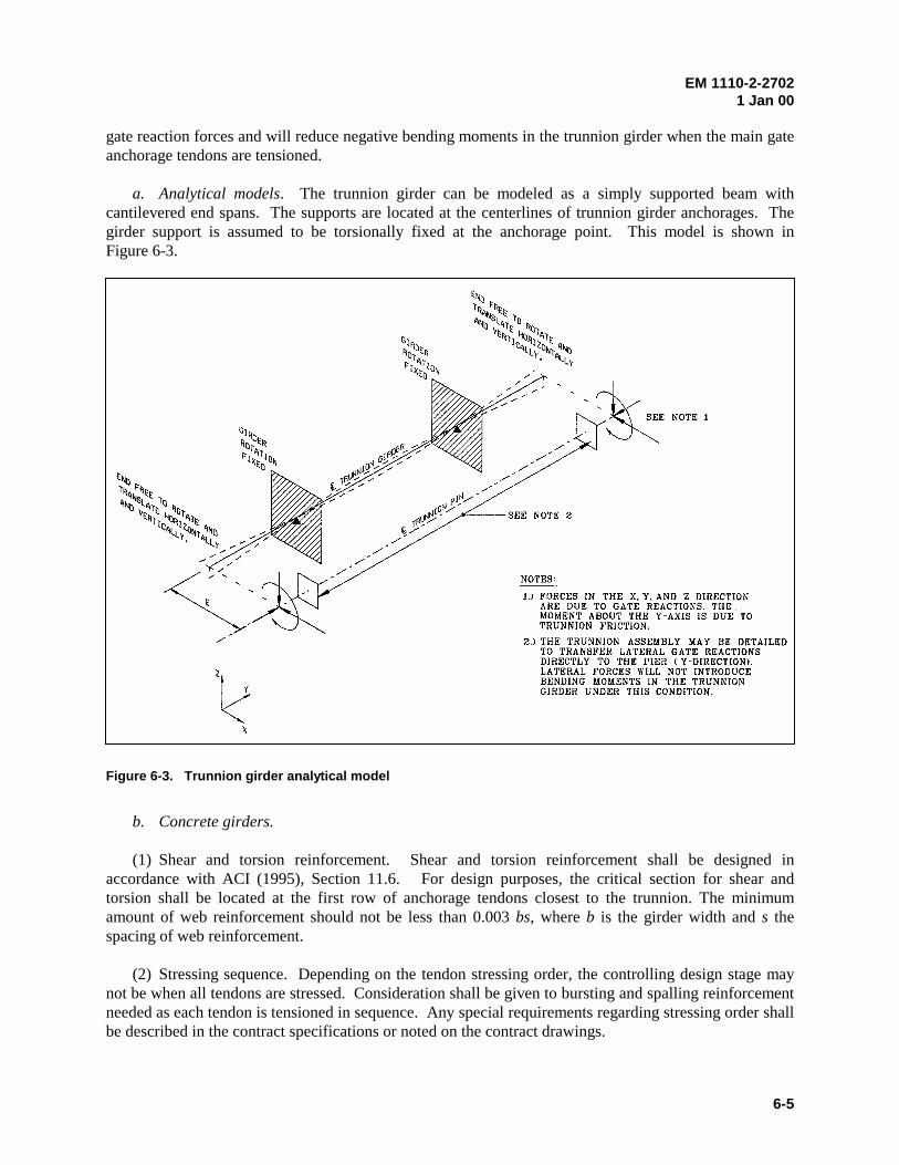
EM 1110-2-27021 Jan 00
6-5
gate reaction forces and will reduce negative bending moments in the trunnion girder when the main gateanchorage tendons are tensioned.
a. Analytical models. The trunnion girder can be modeled as a simply supported beam withcantilevered end spans. The supports are located at the centerlines of trunnion girder anchorages. Thegirder support is assumed to be torsionally fixed at the anchorage point. This model is shown inFigure 6-3.
b. Concrete girders.
(1) Shear and torsion reinforcement. Shear and torsion reinforcement shall be designed inaccordance with ACI (1995), Section 11.6. For design purposes, the critical section for shear andtorsion shall be located at the first row of anchorage tendons closest to the trunnion. The minimumamount of web reinforcement should not be less than 0.003 bs, where b is the girder width and s thespacing of web reinforcement.
(2) Stressing sequence. Depending on the tendon stressing order, the controlling design stage maynot be when all tendons are stressed. Consideration shall be given to bursting and spalling reinforcementneeded as each tendon is tensioned in sequence. Any special requirements regarding stressing order shallbe described in the contract specifications or noted on the contract drawings.
Figure 6-3. Trunnion girder analytical model
EM 1110-2-27021 Jan 00
6-6
(3) Anchorage zones. Anchorage zone reinforcement to resist bursting, edge tension, and spallingshall be designed in accordance with AASHTO (1994), Section 5.10.9. This applies to anchorage zonescorresponding to the girder longitudinal tendons and those due to girder anchorage forces (bearing areasbetween the trunnion girder and pier).
c. Steel girders.
(1) Stability. Beam flanges and webs should be proportioned to satisfy compact sectionrequirements to avoid local buckling. Where compact sections are not practical, noncompact sections areallowed; however, slender elements shall not be used. Transverse stiffeners may be used to provideincreased web stiffness. Where required, transverse stiffeners shall be designed in accordance with AISC(1994), Chapter F. The limit state of lateral torsional buckling is generally not a concern for box girdersdue to the relatively stiff cross sections. However, lateral torsional buckling may be a concern for I-shaped trunnion girders. In evaluating lateral torsional buckling, the unsupported length is generallydetermined assuming that the girder is braced at the centerlines of anchorage groups.
(2) Anchorage tendon supports. Specific members are generally required to provide support to resistthe anchorage system posttensioning loads. These members may be comprised of steel plates, pipes, ortubes. Stiffener plates may be mounted on each side of an anchor and welded to the interior flanges ofthe girder. These plates may also serve as web or flange stiffeners. Pipes or tubes may also be mountedto the interior flanges and anchors passed through the inside of the pipes or tubes. Members shall bedesigned to resist jacking loads as described in paragraph 6-4.b(2). Steel plates should be designed asedge loaded flat plates, and pipes or tubes should be designed as axially loaded columns with boundaryconditions that are consistent with the detailing.
6-6. Serviceability Requirements
a. Corrosion protection for concrete girder components. Ducts for tendons shall be morter tightand shall be grout-filled subsequent to posttensioning. Ducts shall be nonreactive with concrete, tendons,and grout and shall have an inside of diameter at least 6 mm (1/4 in.) larger than the tendon diameter.Anchorage devices shall be encapsulated by second-placement concrete.
b. Corrosion protection for steel girders. Corrosion protection for steel trunnion girders consists ofprotective coatings. I-shaped and open-end box-shaped girders may be painted, metalized, or hot-dipgalvanized. Closed-end box-shaped girders may be galvanized. Box girders must include access holesfor penetration of galvanizing material to the interior of the girder. The designer should locate potentialgalvanizers to assure that the size of girder can be accommodated. Bituminous fillers may be used to fillrecesses and isolated pockets to promote proper drainage. Chapter 8 provides additional information oncoatings.
c. Steel girder deflection. Deflections of steel girders due to service loads shall be evaluated foreffects on tainter gate operation. Deflections shall be limited so that design stresses for bearings are notexceeded, maximum allowable bearing rotations are not exceeded (for spherical bearings), gate sealcontact surfaces are maintained within acceptable tolerances, machinery loads are not exceeded, and gateand girder anchorage design assumptions are not compromised. For small gates (i.e., less than 15 m(50 ft) wide or 7 m (23 ft) high), acceptable deformations shall be determined by the owner and verifiedby standard engineering practice. For gates larger than this, steel girders shall be designed to achieve thesame stiffness characteristics of a typical concrete girder proportioned to resist the same loading.
EM 1110-2-27021 Jan 00
6-7
Alternatively, deflections may be calculated and the impact on operability determined. Such analysesshall be conducted using advanced 3-D analysis techniques such as the finite element method.
6-7. Design Details
a. Concrete girders.
(1) It has been common practice to require that the trunnion girder be completely posttensioned priorto placing adjacent pier concrete and tensioning the girder anchorage. This was done because shorteningof the girder due to posttensioning would be restricted by bond to the adjacent concrete at points ofbearing. This requirement can cause delays in the construction schedule. The use of second-placementconcrete can be incorporated in the area between the pier and girder to eliminate this concern.
(2) Torsional reinforcement shall be provided in the form of closed stirrups. As an aid inconstruction, it is suggested that the conventional reinforcement be assembled as a cage with the websteel fabricated in a welded grid arrangement and welded to surrounding hoops and longitudinal steel.The longitudinal bars should not be too large since the posttensioning of the girders will have a tendencyto cause buckling of these bars and may cause spalling of the concrete.
(3) The tendon spacing for the longitudinal posttensioning steel must be offset with respect to thetrunnion girder anchorage tendons, allowing adequate clearance for concrete placement between ductsfor longitudinal and anchorage steel. A 178-mm (7-in.) grid spacing for both the longitudinal girder andmain gate anchorage tendons has been used satisfactorily in previous designs.
b. Steel girders.
(1) Consideration should be given for working room by selecting web depths and spacing of tendonsupports and stiffeners so that welding can be performed without difficulty. It is recommended toprovide a minimum of 200 mm (8 in.) of working room at a 45-deg angle to perpendicular members at aweld joint. If tighter working room is required by other constraints, potential fabricators should be con-sulted for requirements. Consideration should also be given for working room for weld test equipment.
(2) I-shaped girders are easier to fabricate than are box-shaped girders. Weld joints for flange-to-web welds and tendon support members are easily accessed. Box-shaped girders are more difficult tofabricate when center-mount trunnions and tendon supports are incorporated. The top plate may beinstalled in sections if welding to intermediate plates is required. Allowance for welding access maycontrol member selection and sizing so that adequate working room is provided and quality welding canbe assured.
6-8. Fracture Control
a. Material selection. Proper material selection and fabrication details and procedures will aid incontrol of brittle behavior of steel girders. To enhance ductile behavior, specified materials should eitherinclude mild carbon steels or maintain a carbon equivalent conducive to good welding. Weld metalshould meet AWS matching filler metal requirements. Stringent toughness requirements should be con-sidered for cold regions and where large welds (welds greater than 1 in.) are used. Toughness require-ments shall be in accordance with EM 1110-2-2105.
EM 1110-2-27021 Jan 00
6-8
b. Weld details. Girder end and interior stiffener or support plates should be coped at the corners toavoid intersecting welds and to provide access for coating materials. Where possible, large welds shouldbe avoided by specifying double-bevel, full-penetration or partial-penetration groove welds, and byreplacing single thick plates with multiple thinner plates. For all welding, AWS requirements should bespecified for weld details, heat treatment, and matching filler metal. Stress relieving should be consideredfor girders with thick plates and high restraint.
c. Nondestructive testing. All structural joints and large welds should be 100 percent tested usingultrasonic or radiographic testing. Appendix B provides additional information on welding.
EM 1110-2-27021 Jan 00
7-1
Chapter 7Operating Equipment
7-1. Introduction
a. General. Traditionally, tainter gates have been operated by lifting with wire rope or chains attachedto a hoist located above the gate. More recently, hydraulic hoist systems have also been utilized to operatetainter gates due to economy, reduced maintenance, and advantages concerning operating multiple gates. Chainhoists are not recommended for new designs due to past maintenance problems. The components of the liftingequipment associated with the gate shall be designed to withstand forces including the weight of the gate, siltand ice loads, and friction loads (side seals and trunnion) using the load cases defined in Chapter 3.Component design of the lifting machinery is the responsibility of the mechanical engineer.
b. Coordination. The design process is an iterative procedure where alternate hoist arrangements areevaluated jointly with the structural systems of the tainter gate and pier to arrive at a design that minimizescost. Throughout this process, the structural engineer requires the technical assistance of a hydraulic engineerand a mechanical engineer. The hydraulic engineer specifies the opening requirements and flow nappes forvarious flood events. The location and layout of the machinery is dependent on gate opening requirements,and the flow nappe is needed so that the cylinder for hydraulic hoist systems can be located to avoidsubmergence. The mechanical engineer designs the operating machinery and determines the layout ofoperating machinery and operating machinery design loads. There are many acceptable solutions for the layoutof the machinery and each alternate geometry will result in a different system design. For example, therequirements for a hydraulic cylinder (stroke length, bore, piston rod diameter, and operating pressure) andresulting machinery loads will be affected by the layout of the cylinders. The tainter gate design (and possiblythe anchorage and pier design) is affected by the unique machinery loads of each layout. The optimum layoutis determined by jointly evaluating overall costs of the hoist system, tainter gate, gate anchorage, and pier.
7-2. Machinery Description
a. Hydraulic hoist. A hydraulic hoist system consists of two synchronized hydraulic cylinders asdescribed in paragraph 3-2.c (Figure 3-7). Each cylinder is mounted on the adjacent pier with a trunnion andis connected to the downstream side of the gate with a pin connection. The connection between the cylinderand gate is generally made near the end of a horizontal girder or at a connection in the end frame. The cylinderlocation should be selected to provide a practical connection to the gate and to minimize hoist loads whilemaintaining a relatively constant cylinder load through the required range of motion. The arrangement mustaccommodate required angular movement necessary to lift the gate through the range of motion. The cylinderposition and point of connection of the cylinder to the gate affects the entire structural design and coordinationbetween designers of the cylinder and gate is essential. Layout of the hydraulic cylinder is discussed inChapter 3.
b. Wire rope hoist. A typical wire rope hoist consists of single or multiple wire ropes attached to eachend of the gate, wound on overhead drums (Figures 3-6 and 3-8). The drums can be interconnected with ashaft and powered by a single motor or powered individually with synchronized motors. Although ropes canbe attached to the upstream or downstream side of a gate, common practice is to attach ropes to the upstreamface of the gate at lifting hitches located near the bottom of the gate. The hoist is typically located so that thewire ropes are in contact with the skin plate for the full height of the gate (in closed position) to preventfloating debris from becoming lodged between the gate face and the wire rope. A detailed discussion on thelocation of the wire rope and associated hoists is provided in Chapter 3.
EM 1110-2-27021 Jan 00
7-2
7-3. Machinery and Gate Loads
For all of the load cases described in paragraph 3-4.b, the operating machinery may be loaded and includesome force. Regarding gate design, the effect of the machinery is considered to be a gate reaction for casesin which the machinery supports the gate, and an applied load when the gate is supported otherwise. For allof the load cases with variable gate position, the machinery force varies in magnitude and direction throughoutthe range of motion. Therefore, for load cases 2, 3, and 4 of paragraph 3-4.b, all positions through theoperating range must be accounted for in design of the gate and operating equipment.
a. Machinery loads. Operating machinery must have the capacity to support the gate during operation.Given the load requirements specified in paragraph 3-4.b, the required capacity is determined from the gateoperating load conditions (load cases 2 and 3), in which the machinery loads are treated as gate reaction forces.The machinery load requirements are the reaction forces since these are the forces required to operate the gate.In determining the machinery design loads, coordination between the project structural and mechanicalengineer is essential.
b. Gate loads. Due to application of appropriate factors of safety and machinery efficiency requirements,the actual maximum machinery capacity can be much larger than that required to operate the gate. Loads Q,described in paragraph 3-4.b(1) and applied in load cases 1, 4, and 5, are based on the actual machinery force.Determination of the magnitude of Q is discussed in paragraph 7-3.c.
(1) Hydraulic hoist. The hydraulic cylinders apply a concentrated load to the gate where the cylinder isattached to the gate. Hydraulic hoists may exert upward as well as downward forces when the gate is closed(load case 1) or jammed (load case 4). The cylinder and associated connections at the pier and gate must bedesigned to withstand the cylinder force. The force over the operational range must be considered, since thecylinder force and its affect on the tainter gate changes with changing gate position.
(2) Wire rope hoist. As opposed to hydraulic hoists, wire rope hoists can exert only upward forces. Thewire rope includes a tension force, and where the rope bears on the skin plate, radial contact pressure isapplied. The rope always exerts a concentrated force at the lifting hitch, and when the wire rope is not tangentto the top of the gate, a concentrated reaction force occurs at the change in rope profile (paragraph 3-2.c(5)).The lifting hitch and supporting members must be designed to withstand the concentrated rope force, and theskin plate and supporting members must be sized to withstand the contact pressure and any reaction due tochange in rope profile. For design, the entire operational range must be considered, since the cable force andits affect on the tainter gate changes with changing gate position.
c. Gate load magnitude.
(1) Hydraulic hoist. Machinery loads applied to the gate (Q) are defined in paragraph 3-4.b(1), and thespecific magnitude shall be determined in consultation with the mechanical engineer. The maximumdownward load Q1 is a function of the relief valve setting, the operational range of the relief valve, anddynamic effects of fluid pressure surges when gate movement stops upon impact with the sill. A back-pressurevalve controls lowering of the gate. It is set to the minimum value required to hold the gate in any openposition. A lowering control relief valve (with a backup) set at 330 Kpa (50 psi) above the back-pressure valveshould be provided to relieve the pressure side of the cylinder and protect the system if the gate jams whileclosing and when the gate impacts the sill. This relief valve setting and the resultant downward load that thecylinder exerts establish the Q1 load. If a relief valve fails, extreme loading may be possible. Use of reliefvalves in parallel limits the possibility of valve failure and is more economical than constructing a structuralsystem capable of resisting this condition. As shown by Figure 7-1, the at-rest downward load Q2 is a functionof the dead weight of the piston and rod WROD and a hydraulic cylinder force P. The force P is that which
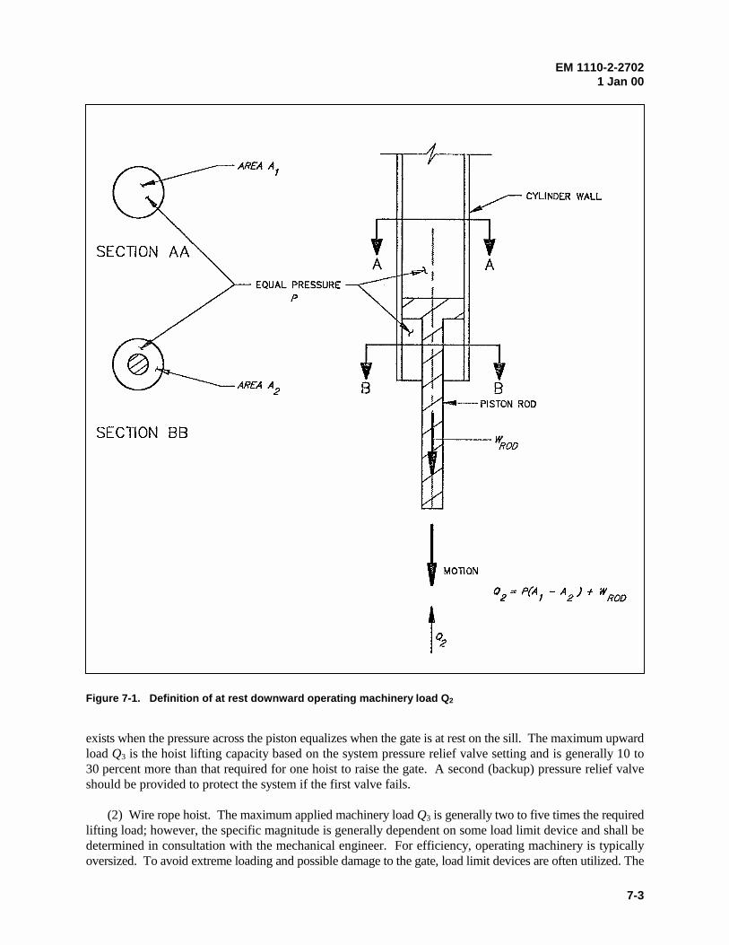
EM 1110-2-27021 Jan 00
7-3
exists when the pressure across the piston equalizes when the gate is at rest on the sill. The maximum upwardload Q3 is the hoist lifting capacity based on the system pressure relief valve setting and is generally 10 to30 percent more than that required for one hoist to raise the gate. A second (backup) pressure relief valveshould be provided to protect the system if the first valve fails.
(2) Wire rope hoist. The maximum applied machinery load Q3 is generally two to five times the requiredlifting load; however, the specific magnitude is generally dependent on some load limit device and shall bedetermined in consultation with the mechanical engineer. For efficiency, operating machinery is typicallyoversized. To avoid extreme loading and possible damage to the gate, load limit devices are often utilized. The
Figure 7-1. Definition of at rest downward operating machinery load Q2
EM 1110-2-27021 Jan 00
7-4
overall reliability of the structure is influenced and possibly controlled by the reliability of these load limitingdevices. Certain devices have had low reliability (i.e., mechanical switches) and should be avoided. A loadlimit system with a high degree of reliability should be used and the load limit should be well defined.
7-4. Machinery Selection
The type of operating machinery can include either the wire rope hoist or hydraulic hoist and the selection oftype should be based on project specific conditions. For a new design, the primary advantages of the wirerope hoist are that the connection is easily made on the upstream face of the gate (increases moment arm forlifting force) and that there are no environmental concerns of oil spillage. For repair or rehabilitation ofexisting projects, wire rope hoists may be the only practical alternative. Advantages of hydraulic hoists includethe following: a) they are generally more economical especially for relatively large lifting capacities; b) theycan apply force in opening and closing; c) several gates can be operated with the same power unit; d) theyrequire low maintenance compared to wire rope systems; and e) they generally require shorter piers for supportcompared to wire rope systems.
EM 1110-2-27021 Jan 00
8-1
Chapter 8Corrosion Control
8-1. General Considerations
Corrosion damage will occur over time and can seriously impair structural and operational capacity of taintergates. To minimize future structural problems and high maintenance and rehabilitation costs, resistance tocorrosion must be considered in the design process. Tainter gates are vulnerable primarily to localizedcorrosion (i.e., crevice corrosion or pitting corrosion), general atmospheric corrosion, or mechanically assistedcorrosion. Brief theoretical discussions on corrosion are presented in EM 1110-2-3400 and CASE (1993).Prudent design and maintenance practices can minimize the occurrence of these types of corrosion. Corrosionin tainter gates is best controlled by application of protective coatings but can be minimized with the properselection of materials and proper design of details. Cathodic protection systems can be applied but are not verycommon on tainter gates. The selection of corrosion protection alternatives is highly dependent on theparticular environment in which the gate will function.
8-2. Material Selection and Coating Systems
a. Material selection. Except for unusual cases, there are few options in selecting materials for theconstruction of tainter gates. Structural members on tainter gates should be constructed of all-purpose carbongrade steel (such as ASTM A36) or high-strength, low-alloy steel (such as ASTM A572, grade 50). Steel thatis available today often has a dual certification. Weathering steel (atmospheric corrosion resistant, high-strength low-alloy steel, ASTM A242 or ASTM A588) that is uncoated is not recommended for use inconstruction of tainter gates or trunnion girders. Coated weathering steel might be warranted in certainconditions. Protective coatings applied to weathering steel typically provide longer corrosion life than thoseapplied to other steels. The initial cost of weathering steel is generally higher than that of other high-strength,low-alloy steels, but the additional cost of coated weathering steel may be offset by the reduced maintenancecosts. Embedded items that are difficult to maintain (including the sill plate and side-seal rubbing plate)should be constructed of stainless steel, and trunnion bushings are generally bronze. All carbon grade or high-strength, low-alloy steel should be coated. Where dissimilar metals are in contact, rubber gaskets or equivalentinsulators should separate them. Generally, this is not necessary for stainless steel bolts, because the area ofcontact between the bolt and structural steel is very small.
b. Coating systems. Application of coating systems is the primary method of corrosion protection fortainter gates. For normal atmospheric exposure, alkyd enamel and aluminum-based systems provide adequateprotection. For gates subject to frequent wetting and fresh water immersion, vinyl systems generally performthe best. For salt water and brackish water environments, coal tar epoxy systems are most effective. In general,vinyl systems are the most appropriate for tainter gates. Metalizing should be considered for conditions thatare predicted to include extreme abrasion conditions due to ice and debris or where there are stringentregulations governing the use of volatile organic compounds (VOC). EM 1110-2-3400, CWGS 09940, andCWGS 05036 provide detailed information on selection, application, and specifications of coating systems.
8-3. Cathodic Protection
For gates or portions of gates that are usually submerged, cathodic protection should be considered tosupplement the paint coatings. Since corrosion is a continuing process of removing electrons from the steel,cathodic protection introduces a slow current to counteract this effect. This essentially causes all parts of thestructure to be cathodic. Cathodic protection is achieved by applying a direct current to the structure from
EM 1110-2-27021 Jan 00
8-2
some outside source. The direct current can be invoked either by impressed current or sacrificial anodesattached to the gate. CWGS-16643, provides guidance on impressed current cathodic protection systems formiter gates. Many of the same basic principles can be applied to tainter gates.
8-4. Design Details
Crevices, areas where ponding water may accumulate, locations where dissimilar metals are in contact, andareas subject to erosion are all susceptible to corrosion. Structural detailing has a significant impact on thestructure's susceptibility to corrosion. Structures should be detailed to avoid conditions that contribute tocorrosion. The following items should be considered in the design process.
a. Structural members should be detailed such that all exposed portions of the structure can be paintedproperly. Break sharp corners or edges to allow paint to adhere properly.
b. Drain holes should be provided to prevent entrapment of water. Extra large drain holes located inareas where the silt may be trapped (i.e., where member connections form open-ended chambers) areappropriate.
c. Lap joints should be avoided, but where used, the joint should be welded so that water can not betrapped between the connected plates.
d. Weld ends, slag, weld splatter, or any other deposits should be ground from the steel. These are areasthat form crevices and can trap water. Use continuous welds.
e. Where dissimilar metals are in contact (generally carbon steel and either stainless steel or bronze), anelectric insulator should be provided between the two metals. Large cathode (stainless steel)-to-anode (carbonsteel) area ratios should be avoided. Surfaces of both metals should be painted. If only the anode metal ispainted and there is a small defect in the coating, the cathode-to-anode area ratio will be very large and rapidcorrosion can occur.
f. Where possible, welds should be used in lieu of bolts, considering the effect on fracture resistance. In general, welded connections are more resistant to corrosion than bolted connections. In bolted connections,small volumes of water can be trapped under fasteners and between plies that are not sealed.
g. In some cases, specifying a uniform increase in member component thickness provides a structure withincreased resistance to corrosion damage. However, this is not recommended as a general practice. This is noteffective for localized corrosion, the total structural cost is increased, and the increase in member resistanceto tension, compression, and bending effects is not uniform.
h. If a protective coating must be applied, steel must generally be sandblasted prior to painting, andaccessibility for sandblasting should be considered. A sandblasting hose generally cannot be bent.
EM 1110-2-27021 Jan 00
A-1
Appendix AReferences
A-1. Required Publications
ER 1110-2-100Periodic Inspection and Continuing Evaluation of Completed Civil Works Structures
ER 1110-2-1150Engineering and Design for Civil Works Projects
ER 1110-2-8157Responsibility for Hydraulic Steel Structures
EM 1110-2-1603Hydraulic Design of Spillways
EM 1110-2-1605Hydraulic Design of Navigation Dams
EM 1110-2-2105Design of Hydraulic Steel Structures
EM 1110-2-2607Planning and Design of Navigation Dams
EM 1110-2-3400Painting: New Construction and Maintenance
EM 1110-8-1 (FR)Winter Navigation on Inland Waterways
CWGS 05036Metallizing: Hydraulic Structures
CEGS 05090Welding, Structural
CEGS 05091Ultrasonic Inspection of Weldments
CWGS 05101Metalwork Fabrication, Machine Work, Miscellaneous Provisions
CEGS 05120Structural Steel
EM 1110-2-27021 Jan 00
A-2
CWGS 05502Metals: Miscellaneous, Standard Articles, Shop Fabricated Items
CWGS 05913Tainter Gates and Anchorages
CWGS 09940Painting: Hydraulic Structures
CWGS 16643Cathodic Protection System (Impressed Current) for Lock Miter Gates
American Association of State Highway & Transportation Officials (AASHTO) 1994“AASHTO LRFD Bridge Design Specifications,” First Edition, Washington, DC.
American Association of State Highway & Transportation Officials/ American Welding Society(AASHTO) 1995 “Bridge Welding Code.” Designation ANSI/AASHTO/AWS D1.5-95, Miami, FL.
American Concrete Institute (ACI) 1995“Building Code Requirements for Reinforced Concrete (ACI 318-95) and Commentary (ACI 318R-95). Farmington Hills, MI.
American Institute of Steel Construction (AISC) 1992“Code of Standard Practice for Steel Buildings and Bridges,” Designation AISC S303, Chicago, IL. American Institute of Steel Construction (AISC) 1994“Load and Resistance Factor Design Manual of Steel Construction,” Second Edition, Chicago, IL.
American Society of Civil Engineers (ASCE) 1995“Minimum Design Loads for Buildings and Other Structures,” Designation ASCE7-95, New York.
American Society for Testing and Materials (ASTM) 1995American Society for Testing and Materials, A27/A27M, Standard Specification for Steel Castings,Carbon, for General Application, West Conshohocken, PA.
American Society for Testing and Materials (ASTM) 1997American Society for Testing and Materials, A36/A36M, Standard Specification for Carbon StructuralSteel, West Conshohocken, PA.
American Society for Testing and Materials (ASTM) 1997American Society for Testing and Materials, A53, Standard Specification for Pipe, Steel, Black and Hot-Dipped, Zinc-Coated, Welded and Seamless, West Conshohocken, PA.
American Society for Testing and Materials (ASTM) 1993American Society for Testing and Materials, A148/A148M, Standard Specification for Steel Castings,High Strength, for Structural Purposes E1-1997, West Conshohocken, PA.

EM 1110-2-27021 Jan 00
A-3
American Society for Testing and Materials (ASTM) 1997American Society for Testing and Materials, A240/A240M, Standard Specification for Heat-ResistingChromium and Chromium Nickel Stainless Steel Plate, Sheet, and Strip for Pressure Vessels, WestConshohocken, PA.
American Society for Testing and Materials (ASTM) 1997American Society for Testing and Materials, A242/A242M, Standard Specification for High-StrengthLow-Alloy Structural Steel; AASHTO No.: M161, West Conshohocken, PA.
American Society for Testing and Materials (ASTM) 1997American Society for Testing and Materials, A276, Standard Specification for Stainless Steel Bars andShapes, West Conshohocken, PA.
American Society for Testing and Materials (ASTM) 1997American Society for Testing and Materials, A354, Standard Specification for Quenched and TemperedAlloy Steel Bolts, Studs, and Other Externally Threaded Fasteners, West Conshohocken, PA.
American Society for Testing and Materials (ASTM) 1997American Society for Testing and Materials, A416/416M, Standard Specification for Steel Strand,Uncoated Seven-Wire for Prestressed Concrete, West Conshohocken, PA.
American Society for Testing and Materials (ASTM) 1996American Society for Testing and Materials, A435/A435M, Standard Specification for Straight-BeamUltrasonic Examination of Steel Plates R (1996), West Conshohocken, PA.
American Society for Testing and Materials (ASTM) 1997American Society for Testing and Materials, A572/A572M, Standard Specification for High-StrengthLow-Alloy Columbium-Vanadium Structural Steel; AASHTO No.: M223, West Conshohocken, PA.
American Society for Testing and Materials (ASTM) 1997American Society for Testing and Materials, A588/A588M, Standard Specification for High-StrengthLow-Alloy Structural Steel with 50 ksi (345 Mpa) Minimum Yield Point to 4 in. (100 mm) Thick; AASHTONo.: M222, West Conshohocken, PA.
American Society for Testing and Materials (ASTM) 1996American Society for Testing and Materials, A615/A615M, Standard Specification for Deformed andPlain Billet-Steel Bars for Concrete Reinforcement; AASHTO No.: M31, West Conshohocken, PA.
American Society for Testing and Materials (ASTM) 1996American Society for Testing and Materials, A616/A616M, Standard Specification for Rail-SteelDeformed and Plain Bars for Concrete Reinforcement; AASHTO No.: M42, West Conshohocken, PA.
American Society for Testing and Materials (ASTM) 1996American Society for Testing and Materials, A617/A617M, Standard Specification for Axle-SteelDeformed and Plain Bars for Concrete Reinforcement; AASHTO No.: M53, West Conshohocken, PA.
American Society for Testing and Materials (ASTM) 1996American Society for Testing and Materials, A668/A668M, Standard Specification for Steel Forgings,Carbon and Alloy, for General Industrial Use E1; AASHTO No.: M102, West Conshohocken, PA.
EM 1110-2-27021 Jan 00
A-4
American Society for Testing and Materials (ASTM) 1995American Society for Testing and Materials, A705/A705M, Standard Specification for Age-HardeningStainless Steel Forgings, West Conshohocken, PA.
American Society for Testing and Materials (ASTM) 1996American Society for Testing and Materials, A706/A706M, Standard Specification for Low-Alloy SteelDeformed and Plain Bars for Concrete Reinforcement, West Conshohocken, PA.
American Society for Testing and Materials (ASTM) 1997American Society for Testing and Materials, A722/A722M, Standard Specification for Uncoated High-Strength Steel Bar for Prestressing Concrete, West Conshohocken, PA.
American Society for Testing and Materials (ASTM) 1996American Society for Testing and Materials, A770/A770M, Standard Specification for Through-thicknessTension Testing of Steel Plates for Special Applications E1-1991 R (1996), West Conshohocken, PA.
American Society for Testing and Materials (ASTM) 1995American Society for Testing and Materials, A772/A772M, Standard Test Method for ac MagneticPermeability of Materials Using Sine Current, West Conshohocken, PA.
American Society for Testing and Materials (ASTM) 1995American Society for Testing and Materials, B22, Standard Specification for Bronze Castings for Bridgesand Turntables, West Conshohocken, PA.
American Society for Testing and Materials (ASTM) 1997American Society for Testing and Materials, B148, Standard Specification for Aluminum-Bronze SandCastings, West Conshohocken, PA.
American Society for Testing and Materials (ASTM) 1994American Society for Testing and Materials, G46, Standard Specification for Examination and Evaluationof Pitting Corrosion, West Conshohocken, PA.
American National Standards Institute/ American Welding Society 1986“Guide for the Nondestructive Inspection of Welds,” Designation ANSI/AWS B1.10-86, Miami, FL.
American Welding Society 1991“Welding Handbook,” Eighth Edition, Miami, FL.
American Welding Society 1996“Structural Welding Code – Steel,” Designation ANSI/AWS D1.1-96, Miami, FL.
CASE Steel Structures Task Group 1993“Steel Structures for Civil Works, General Considerations for Design and Rehabilitation,” TechnicalReport ITL-93-2, U.S. Army Engineer Waterways Experiment Station, Vicksburg, MS.
Cox 1972Cox, R. G. 1972. “Pertinent Data on Spillway Tainter Gates for Corps of Engineers Projects,”Miscellaneous Paper H-72-7, U.S. Army Engineer Waterways Experiment Station, Vicksburg, MS.
EM 1110-2-27021 Jan 00
A-5
Greimann, Stecker, and Rens 1990Greimann, L., Stecker, J., and Rens, K. 1990. “Management System for Miter Lock Gates,” TechnicalReport REMR-OM-08, U.S. Army Engineer Waterways Experiment Station, Vicksburg, MS.
Haynes, Haehnel, Clark, and Zabilansky 1997Haynes, F. D., Haehnel, R., Clark, C., and Zabilansky, L. 1997. “Ice Control Techniques for CorpsProjects,” Technical Report REMR-HY-14, U.S. Army Engineer Waterways Experiment Station,Vicksburg, MS.
Kumar and Odeh 1989Kumar, A., and Odeh, A. A. 1989. “Mechanical Properties and Corrosion Behavior of Stainless Steels forLocks, Dams, and Hydroelectric Plant Applications,” Technical Report REMR-EM-6, U.S. Army EngineerWaterways Experiment Station, Vicksburg, MS.
Shore Protection Manual 1984Shore Protection Manual. 1984. 4th ed., 2 Vol, U.S. Army Engineer Waterways Experiment Station,U.S. Government Printing Office, Washington, DC.
Westergaard 1931Westergaard, H. 1931. Water Pressure on Dams During Earthquakes, Transactions ASCE, New York,NY, Paper No. 1835, pp 418-433.
EM 1110-2-27021 Jan 00
B-1
Appendix BDesign and Specification Considerations for Fabrication and Erection
B-1. General Considerations
This appendix presents general design considerations and provides guidance on preparation of technicalproject specifications regarding fabrication and erection of tainter gates. Civil works guide specifications(CWGS) and military construction guide specifications (CEGS) may be used as a guide for preparingproject specifications; however, the engineer must ensure that these specifications are tailored to reflectproject specific requirements as required by Engineer Regulation (ER) 1110-2-8157.1 Applicable CWGSand CEGS include CWGS 05913, CWGS 05101, CWGS 05502, CEGS 05120, CEGS 05090, and CEGS05091. Engineer Manual (EM) 1110-2-2105 provides guidance for preparation of project technicalspecifications for steel used in hydraulic steel structures.
a. General specification requirements. Generally, the requirements for gate fabrication,installation, erection, and operational testing given in CWGS 05913 will apply. CWGS 05913 shall beedited to include project specific requirements consistent with guidance specified herein. Specialconsiderations for critical or fracture critical members must be developed and specified. Although notincluded in CWGS 05913, bolted connections and framing members of American Society for Testing andMaterials (ASTM) A 572 structural steel may be used in the construction of tainter gates. Where boltedconstruction and/or ASTM A 572 structural steel is specified, drawings and specifications shall be editedaccordingly. In conformance with EM 1110-2-2105, project specifications should require fullpretensioning of high-strength bolts for all bolted connections. Construction erection shall conform torequirements of American Institute of Steel Construction (AISC) S303, Sections 7 and 8.
b. Access and dimensional tolerance.
(1) Access design considerations. Members should be located and proportioned to provide sufficientaccess for workers and equipment required for fabrication, painting, and inspection. For example, thereshould be sufficient access to ensure that a welder has an unobstructed view of the weld root andsufficient space to apply quality welds with correct electrode angle. There should be sufficient access forsandblasting, painting, and inspection equipment and should be provisions (such as access hatches andsafety railing) to provide an inspector access to frequently inspected areas.
(2) Specification tolerance requirements. The project specifications shall include provisions toensure proper fabrication by conformance to American National Standard Institute (ANSI)/AmericanWelding Society (AWS) D1.1 (1996) and AISC S303 (1992) requirements for fabrication and erectiontolerances. (CWGS 05913 provision for alignment of elements that support skin plates is appropriate forwelding of skin plate to supporting elements.) Provisions shall also be included to ensure proper gateoperation and function. CWGS 05913 specifies tolerances for trunnion location and alignment andflatness of side-seal and sill plates. The specified tolerances for trunnion location are generallyappropriate; however, these tolerances shall be determined by the engineer and should based on gate sizeand geometry.
1 References are listed in Appendix A.
EM 1110-2-27021 Jan 00
B-2
B-2. Shop Fabrication
In conformance with CWGS 05913, gates shall be shop fabricated. Where fabrication of the gate inseparate segments is necessary for handling and shipping, segments shall be proportioned to facilitateassembly and to minimize the number of joints to be field-welded. Specifications shall include specificproject dependent requirements on shop fabrication, preassembly, and field fabrication. Splices shall beat areas of low stress, and segments shall be of strength and stiffness to withstand forces imparted duringshipping and erection (considering temporary supports and bracing). When gates must be fabricated insections, the gate shall be preassembled in the shop and appropriate measure shall be taken to reproducethe assembly in the field. Splice locations and associated connection details shall be determined by thedesign engineer and shown on the contract drawings or determined by the contractor and approved by thecontracting officer.
a. Forging and casting. Items to be forged or cast shall be indicated on the drawings. Specifica-tions shall be edited to require that forging and casting for the prescribed material be done in accordancewith the applicable ASTM standard. Recommended ASTM standards are provided in CWGS 05913 andChapter 3.
b. General welding considerations. General welding requirements shall conform to ANSI/AWSD1.1 (1996) as provided in CWGS 05101 and CEGS 05090. For special circumstances not covered (i.e.,welding stainless steel), the engineer shall develop the specific welding requirements and edit thespecifications accordingly, or require approval of contractor developed procedures. Guidance onwelding is provided in EM 1110-2-2105.
c. Complex details. Special considerations may be warranted for fabrication of complex weldeddetails that join main structural members or that include thick plates subject to high constraint. Theengineer shall develop necessary provisions for complex details considering the following guidance andedit the project plans and specifications (CWGS 05101 and CWGS 05913) accordingly.
(1) Vertical rib-to-horizontal girder connection design considerations. The welded vertical rib-to-horizontal girder connection shown in Figure B-1 is difficult to fabricate to provide optimum fractureresistance. Unfavorable conditions that are unavoidable include separation of rib and girder flangesurfaces due to rib curvature, and intersection of vertical (transverse to girder flange) and horizontal(transverse to rib flange) welds. Additionally, relatively poor access for field welding exists since theclearance between girder flange and skin plate is limited by rib depth. Although this connection has beensuitable in most projects, there have been several cases involving cracked and failed connections andspecial considerations are warranted. Historically, welded connections have been used and will continueto be used; however, with appropriate design, bolted connections are appropriate and have someadvantages over welded connections.
(a) Welded connection considerations. The connection between the rib and girder is generally field-welded subsequent to fabrication of the skin plate assembly and girders. The designer shall ensure thatrib depth is enough to provide adequate welding access for vertical welds. Due to the curvature of thevertical ribs, a flat joining of faying surfaces between the flanges of the girder and rib is not possible.Filler plates of thickness necessary to provide bearing between the curved rib flange and girder flangeshall be included. A vertical seal weld of size necessary to fill the gap and cover the fill plate is generallyprovided. If the vertical weld is designed as a structural weld, then ANSI/AWS D1.1 (1996),Section 2.13, applies, and filler plates shall be selected such that the maximum gap between the girderflange and rib flange does not exceed 5 mm (3/16 in.). Generally, the vertical weld joining the edge of
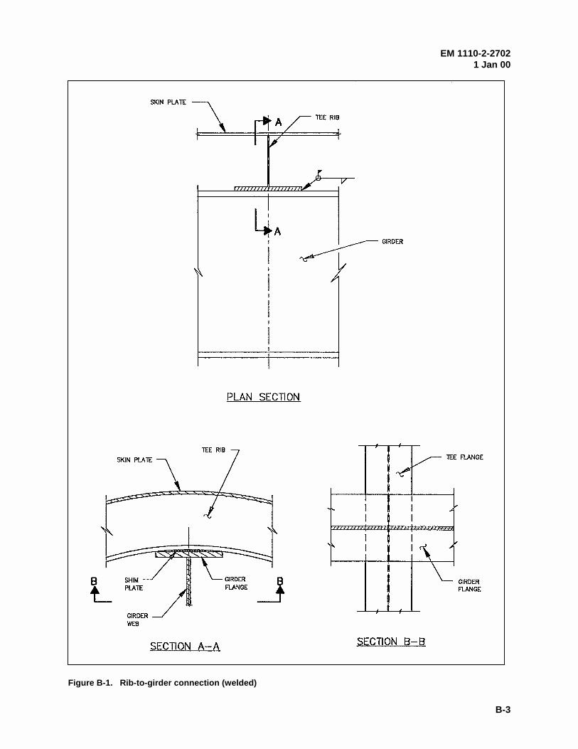
EM 1110-2-27021 Jan 00
B-3
Figure B-1. Rib-to-girder connection (welded)
EM 1110-2-27021 Jan 00
B-4
the rib flange to the girder flange is not a structural weld, since the horizontal weld is of adequatestrength. Additionally, the horizontal and vertical welds are deposited on opposite sides of a commonplane of contact to join the rib flange and girder flange. AISC (1994), Section J2.2, and ANSI/AWSD1.1 (1996), Section 2.4.7.2, require that welds deposited on opposite sides of a common plane ofcontact between two parts be interrupted at a corner common to both welds. This is not possible ifthe overlapping area is sealed. However, to minimize the adverse effects, the horizontal and verticalweld size shall be no larger than that necessary to provide a seal within 25.4 mm (1 in.) of theirintersection.
(b) Bolted connection. The bolted connection alternative consists of an arrangement of four boltsjoining the girder flange and rib flange (Figure B-2). The primary considerations in design are to selectthe appropriate bolt size to withstand the applied loads and to provide a solid bearing between the nut ofthe bolt and the bolt head. This can be accomplished with specially fabricated shims or by using acombination of shims and bevel washers. There must be adequate bearing to withstand full pre-tensioning of the bolts. The bolted connection alternative alleviates the problems associated withwelding including intersecting welds and clearance between the girder flange and skin plate. Theprimary disadvantage is that the overlapping area between flanges of the rib and girder is not sealed fromwater intrusion.
(2) Full-penetration flange welds and weld access holes. At member intersections or splices wherethe flange of a rolled or built-up shape is welded with a full-penetration weld, weld access holes shouldbe provided and detailed in compliance with ANSI/AWS D1.1 (1996), Section 5.17. Groove welds thatdo not have steel backing or back gouging are considered partial-penetration welds regardless of size, andbacking is not possible without a weld access hole through the web. Additionally, without an accesshole, an unfavorable residual stress condition exists where the flange and web welds intersect. Thiscondition exists in the strut-to-girder connection, splices that may exist between the trunnion hubassembly flange plates and end frame struts, and at intersections of end frame members. At criticalconnections for intersecting members, the engineer shall show access hole requirements on the drawingsor require approval of contractor submittals.
(3) Thick plate weldments. Weldments involving thick plates are particularly susceptible to crackingcompared to those of thin plates. (A thick plate is generally considered to be 38 mm (1-1/2 in.) or greaterin thickness.) The structural engineer shall develop a welding procedure (or require approval of acontractor developed procedure) for critical thick plate weldments and edit project specificationsaccordingly. General requirements for welding of thick plates are provided in EM 1110-2-2105.Trunnion yoke plates, trunnion bushing assembly, cable attachment brackets, steel trunnion girders, andbuilt-up members generally include weldments with thick plates and/or high constraint. For the trunnionhub and yoke assemblies, plates are subject to large through-thickness stresses. The designer mayrequire improved through-thickness properties by specifying steel with a maximum sulfur content of 0.01percent and/or verification of resistance to lamellar tearing by testing in accordance with ASTM A 770/A770M.
d. Trunnion. The engineer shall determine specific requirements for yokes, pins, and associatedcladding, hubs, and bushings in accordance with guidance provided in Chapter 4 and edit project plansand specifications (CWGS 05913), accordingly.
e. Trunnion girder and anchorage. The engineer shall determine specific requirements for thetrunnion girder and anchorage in accordance with guidance provided in Chapter 5 and Chapter 6 and editproject plans and specifications (CWGS 05913), accordingly.
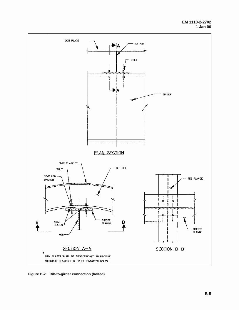
EM 1110-2-27021 Jan 00
B-5
Figure B-2. Rib-to-girder connection (bolted)
EM 1110-2-27021 Jan 00
B-6
f. Welding inspection requirements. CWGS 05101 shall be edited to specify contractorrequirements for weld inspection considering general weld inspection requirements specified inEM 1110-2-2105 and the following:
(1) Prior to welding, thick (greater than 38 mm (1-1/2 in.)) plates of the trunnion hub and yokeassemblies that are subject to through-thickness weld residual stresses shall be examined in accordancewith ASTM A435. In the vicinity of the weld, 100 percent of the plate surface shall be inspected.
(2) Critical groove welds including those in steel trunnion girders, at girder splice locations, at theend frame to girder connection, and trunnion weldments shall be inspected by ultrasonic inspection (UT)and/or radiographic inspection (R). Critical fillet welds are generally best inspected using penetrantinspection (PT) and/or magnetic particle inspection (MT). Critical welds and associated testing methodsshall be determined by the engineer and shall be designated on the contract drawings.
(3) In accordance with ANSI/AASHTO/AWS D1.5 (1995), all tension butt welds of fracture criticalmembers (FCM) shall be inspected using R and UT. All other tension groove welds in FCM shall beinspected by UT. The engineer shall determine all FCM and shall clearly designate all FCM andrequired nondestructive examination on the contract drawings.
B-3. Field Fabrication and Erection
Project specifications (CWGS 05101 and CWGS 05913) shall be edited to ensure conformance tofabrication, erection, and installation requirements specified herein. Specifications shall ensure thatconstruction erection conforms to requirements of AISC S303 (1992), Sections 7 and 8, and thespecifications shall require approval of contractor submitted erection plan prior to construction.
a. Gate assembly. Field assembly of the gate shall be conducted such that the assembledcomponents are not over-stressed or unstable during assembly. The gate shall be assembled inconformance with the shop match markings using temporary supports that shall be removed afterfabrication is completed. Prior to field welding and/or bolting of permanent connections, controllingdimensions and alignments shall be within specified tolerances. All field welding and associatednondestructive examination shall conform to requirements specified herein for shop fabrication. Skinplate welds shall be tested for water tightness after the gates are installed but prior to painting andmounting of seals, and disclosed leaks shall be sealed by appropriate means to be approved by thecontracting officer.
b. Trunnion installation. Trunnion yokes and pins shall be installed and aligned in accordance withrequirements provided in Chapter 4. For greased trunnion systems, the trunnion lubrication system linesshall be purged and filled with grease before the final connection to the gate. Bearing surfaces oftrunnion pins and bushings shall be cleaned and coated with grease prior to installing the trunnion pins.For self-lubricating trunnion systems, bearing surfaces of trunnion pins and bushings shall be cleanedprior to installing gates.
c. Anchorage system and trunnion girder installation. Procedure for installation and anchorage ofthe trunnion girder shall conform to requirements of Chapters 5 and 6.
d. Protective coating and cathodic protection. The engineer shall determine the corrosionprotection considering the project specific environment as discussed in Chapter 2, and guidance providedin Chapter 8 and CWGS 05913 shall be edited accordingly.
EM 1110-2-27021 Jan 00
C-1
Appendix COperation and Maintenance Considerations
C-1. General
To maintain operational capacity is a key consideration in the design of tainter gates. Operationalcapacity may be inhibited by various circumstances including normal deterioration due to corrosion andunintended loading (vibration, accumulation of ice, obstruction, etc.). Optimum operation can be assuredby selection of appropriate design details and by providing continued maintenance and inspection.
C-2. Design Considerations
Tainter gate designs shall include provisions to minimize effects of corrosion and unintended loading andprovisions to provide access required for inspection and maintenance. In addition to a protective coatingsystem, corrosion can be controlled by appropriate detailing. Unintended loading is minimized by properdesign of seal details, ice control, and trunnion lubrication. Bulkheads and safety devices provide accessfor inspection and maintenance.
a. Design details for corrosion control. Using continuous welds instead of intermittent welds,rounding sharp corners, and seal welding lap joints can minimize localized corrosion. Structuralmembers should be located such that access for future inspection and necessary maintenance is provided.All areas should be visually accessible and provide access for inspection and painting equipment. Forvery large members, access manholes may be necessary. Provision for drainage should be includedwhere water can accumulate such as on the webs of the girders, end frames, and bracing members. Drainholes should be located in areas that are lowest while the gate is in normal position. The size of hole isdependent on the size of drainage area and generally ranges from 25 mm (1 in.) to 75 mm (3 in.) indiameter. The cut edges of holes should be smooth and free of notches, especially in areas where the cutmember is subject to tensile forces.
b. Control of unintended loading.
(1) Design details to control flow-induced vibration. Flow-induced vibration may occur due to flowunder the gate or over the gate. Regarding flow under the gate, bottom seals of various configurationshave been a source of vibration problems in tainter gates. This vibration can be minimized or eliminatedwith use of proper lip and bottom seal configurations as discussed in paragraph 3-7.a(2). (Otherconfigurations are discussed in EM 1110-2-1605.)1 The girder and bottom lip should be sized to haveadequate stiffness to limit flexing that would permit flow between the lip and sill. Bracing of thecantilevered portion of the skin plate provides rigidity. Vibration (or debris) loading may also occur dueto overtopping water and debris that may impact the upper girder. For conditions where this is a concern,deflector plates positioned to protect the upper horizontal girder will minimize the effects of impactingwater and debris.
(2) Deicing systems. Devices for preventing the formation of ice, or to thaw ice adhering to thegates and seals, are necessary for gates that must be operated in subfreezing weather. Ice formation mayfreeze a gate in place or obstruct motion, and buildup of ice may add sufficient weight to overload gatehoists. Various solutions exist to control ice formation and buildup (Haynes et al. 1997). The most
1 References are listed in Appendix A.
EM 1110-2-27021 Jan 00
C-2
common methods of ice control for tainter gates are use of direct heating systems or air bubbler systems.Direct heating is the most effective means of controlling ice. Air bubbler systems for tainter gates aregenerally slow and inefficient; however, they may be beneficial when used to supplement direct heatingsystems where unusually severe climatic conditions exist.
(a) Direct heating systems. Direct heating units can be installed at appropriate locations on oraround a gate. Generally, heater units consist of steel cells with embedded electric heating elements orheat tape with heat transfer fluid. Heating elements are generally helical formed coil of chrome-nickel,encased in a seamless sheath of corrosion-resisting, nonoxidizing metal. All heater units should bedesigned as removable units so replacement is easily accomplished. Side-seal heaters generally consistof a tubular steel cell with embedded heater elements that is fabricated to fit in a recess behind the side-seal rubbing plate along its length. Another method of heating the side seal is to heat the J-seal directlyby inserting heat tape into the hollow portion of a hollow J-seal. The heated J-seal should be used tosupplement embedded heaters, since the J-seal would prevent ice formation only along the J-seal, whilethe remainder of the side-seal rubbing plate could accumulate ice. Heat tape is discussed in EM 1110-8-1(FR). To control ice formation on gate surfaces, box-type heater units can be attached directly to thedownstream side of the skin plate and/or along the end frame members. These units are essentially flatrectangular steel cells that encase heating coils. The cells are sealed and insulated to direct heat to thegate surface. Radiant (or infrared) heaters provide another means to control ice on gate surfaces (Hayneset al. 1997). These heaters can be suspended in close proximity to the structure and may be practical inareas that are difficult to access.
(b) Air bubbler systems. Air bubbler systems are easy to use and can be custom designed for aparticular project purpose to move ice and reduce ice growth. Bubbler systems consist essentially ofcompressed air circulated through a pipe system. Air can be released through outlets located in front ofthe gate sills to create a circulation of warmer water from the bottom of the reservoir toward the face ofthe gate. This will prevent the formation of ice on the face of the gate and tends to keep an area of openwater upstream from the gates. Air bubbler systems are discussed in EM 1110-8-1 (FR) and Haynes etal. (1997).
(3) Lubrication. Lubrication of the trunnion is a primary design consideration. Lubrication reducestrunnion friction to minimize lifting forces and flexural forces in end frame members. The surface of thetrunnion pin and bushing must be sufficiently lubricated for efficient operation of a gate. Lubrication canbe accomplished by direct application of grease through the hub and bushing to the bushing-pin interface.Grooves are fabricated on the inside face of bushings to contain grease that is injected through holesdrilled in the hub and bushing. Another option is to use self-lubricating bronze bushings.
(4) Debris protection. Unintended forces may occur due to accumulation of debris. Debris maybecome lodged between the gate and adjacent piers resulting in gate binding during lifting or mayaccumulate on gate members adding to the gate weight. Deflector plates can be attached to the end framestruts and on the downstream flange of girders at appropriate locations to provide debris screens. It isrecommended that deflector plates be fabricated of abrasion resistant and lightweight material such asultra-high-molecular-weight polyethylene.
c. Access.
(1) Temporary closure. Means to provide temporary closure between piers for emergency situationsor gate maintenance or repair operations should be considered in design. In some cases, project opera-tion may permit gates to be out of service for a known period, and temporary closure may not be needed.
EM 1110-2-27021 Jan 00
C-3
Vertical lift gates and sectional bulkheads are the most common types of temporary closure structures. Adiscussion on maintenance and emergency closure facilities is included in EM 1110-2-2607.Maintenance bulkheads are generally provided upstream of tainter gates, and downstream if necessary, toaccommodate unwatering between piers to provide a dry area for maintenance or repair activities. Sinceclosure is for planned inspection and maintenance, maintenance bulkheads are designed for static headsand cannot be installed in flowing water. Bulkhead guide slots and sills should be located such that thereis adequate space to permit the installation of maintenance scaffolding for use in maintenance and repairoperations. Other factors that should be considered in determining bulkhead location are pier size andlocation and capability of bulkhead lifting equipment. The emergency bulkheads provide closurebetween piers under flowing conditions. Emergency closures can be provided upstream or downstreamof the tainter gates; on many navigation projects, it may be advantageous to provide closure downstreamof the service gate since many accidents involve barges on the upstream side. The decision to includeemergency closure structures should be based on economic analysis of costs and associated benefits ofemergency closure given a gate failure.
(2) Safety and critical items. Gate stops are attachments that provide a block to prevent a gate frombeing raised past the maximum elevation for safety and operational concerns. Gate stops are generallywelded attachments that extend from the ends of the lower girder between the outside of the gate and thesurface of the pier. When the gate is in the fully raised position, the stops contact stop beams that aremounted on the pier. To provide safe and easy access for inspection and maintenance, handrails andladders may be attached to gate members using welded or bolted connections. The connections shouldbe designed to minimize adverse effects (stress concentration, residual stress) on main structuralmembers. Attachments should be located away from tension zones if possible and good detailingpractice is essential.
C-3. Inspection
ER 1110-2-100 prescribes general requirements for periodic inspection of completed civil worksstructures that are applicable to all project features. Supplemental more specific requirements forinspection of hydraulic steel structures (HSS) are specified in ER 1110-2-8157. The structural engineershall develop an inspection plan for each tainter gate in accordance with requirements of ER 1110-2-8157 and those specified herein. To conduct a detailed inspection for each tainter gate on a project is noteconomical, and detailed inspection must be limited to critical areas. The inspection plan should identifywhich elements require inspection and what nondestructive testing is required for each. The focus of aninspection should be on fracture critical members, and then critical members and connections mostsusceptible to various forms of degradation. Design drawings and computations, previous inspectionreports and all operations/maintenance records since the most recent inspection should be reviewed todevelop the inspection plan.
a. Identification of critical areas. The most critical elements are those that are determined to befracture critical. Fracture critical elements are those that are subject to tensile stresses whose failurewould cause the structure to collapse. Other critical structural elements include those that are mostsusceptible to degradation including fracture and corrosion.
(1) Fracture. Stress level, stress concentration, material thickness (affects residual stress, toughness,and constraint), quality of fabrication (i.e., weld quality, tack welds, intersecting welds, or pooraccessibility), operational vibration or overload, displacement-induced secondary stress, and loaddistribution are each factors that may contribute to fracture. Fracture is most likely to occur at locationswhere high-tension stress and severe stress concentration exist. To identify critical areas for fracture,
EM 1110-2-27021 Jan 00
C-4
locations of moderate-to-high nominal tensile stress level and details that include significant stressconcentrations must be identified. The effects of stress level and sensitive details are combined todetermine the critical areas for inspection. Stress levels are determined by appropriate structural analysisand the severity of stress concentration imposed by a particular detail is reflected by its particular fatiguecategory. Fatigue categories are specified in AISC (1994). Tainter gates generally have significanttensile stresses in the downstream flanges of the girders at the midlength (lower girders are morecritical), in the upstream girder flange and the outside flange of end frame struts near the girder-strutconnections, and where the end frames join the trunnion assemblies. Significant tensile stresses may alsooccur in end frame bracing members (due to trunnion pin friction), and in the upstream flange of skinplate ribs at the horizontal girders. For in-depth engineering inspections, critical areas that should beinspected for cracking are:
(a) Fracture critical components. Fracture critical components may include lifting brackets, liftingcable or hydraulic machinery components, various components of the trunnion assembly and trunnionbeam, girders, and various end frame members. Fracture critical components may vary on differentprojects and shall be determined by the design engineer.
(b) Locations identified as susceptible to fracture or weld-related cracking. Trunnion weldments,trunnion girders (steel), lifting bracket weldments, the girder-rib-skin plate connection on the upstreamgirder flange near the end frames, the bracing-to-downstream girder flange connection near midspan, andthe girder-to-strut connection are areas most susceptible to fracture. At intersecting welds and whereprevious cracks have been repaired by welding are also areas of concern.
(2) Corrosion. Corrosion can occur at any location on a gate; however, certain areas are moresusceptible than others. Sensitivity to corrosion is enhanced at crevices, locations of dissimilar metals,areas subject to erosion, and areas where ponding water or debris may accumulate. Other areas that aresusceptible to corrosion include where it is difficult to adequately apply a protective coating, such as atsharp corners, edges, intermittent welds, and locations of rivets and bolts. Corrosion-susceptiblelocations on tainter gates include trunnions with dissimilar metals, seal connection plates and rib-girderconnections (crevice corrosion and dissimilar metals), locations of bolts (crevice corrosion), drain holes,and general areas where sharp corners, edges, and intermittent welds are located. Other areas wherecorrosion is likely to occur is where heaters are located and at the normal water line.
b. Inspection procedure.
(1) Inspection for cracks. Common nondestructive field methods to inspect for cracking includevisual, penetrant, ultrasonic, and/or magnetic particle inspections. These and other methods aredescribed in detail by ANSI/AWS B1.10 (AWS 1986). Visual examination is the primary inspectionmethod and shall be used to inspect all critical elements. A visual inspection is “hands-on” and requirescareful and close examination (particularly with the aid of a magnifying glass). Critical areas should becleaned prior to the inspection and when necessary, additional lighting should be used. If cracks aresuspected, penetrant, ultrasonic, and/or magnetic particle inspections should be used to confirm theextent of cracking.
(2) Inspection for corrosion. Appropriate tools that may be used to measure and define corrosiondamage include a depth micrometer (to measure pitting), feeler gages ( to quantify the width of a creviceexhibiting corrosion), an ultrasonic thickness gage (for measuring thickness), a tape measure, and acamera. Guidelines to quantify the severity of corrosion damage are given by Greimann, Stecker, and
EM 1110-2-27021 Jan 00
C-5
Rens (1990). Nondestructive inspection techniques to inspect for corrosion damage include visual andultrasonic inspections.
(a) Visual inspection. A visual inspection of all corrosion susceptible areas should be made tolocate, identify, and determine the extent of corrosion. When corrosion is observed, the type, extent, andseverity should be reported. Any failure of the paint system should also be identified. The extent ofpaint system failure and regions of localized discoloration of gate components should be recorded. Inareas where paint failure has occurred, the gate surface should be visually examined for pitting. Whenpitting is present, it should be quantified by using a probe type depth gage following ASTM G46 (1994).
(b) Ultrasonic inspection. Ultrasonic inspection is useful to measure thickness loss and can be usedto obtain a baseline reference for thickness when it is unknown. The thickness of a steel plate or part canbe determined to an accuracy of approximately 0.13 mm (0.005 in.). The technique can be conductedthrough a paint film or through surface corrosion with only a slight loss in accuracy. Where only oneside of a component is accessible, the open surface can be scanned to identify thickness variation overthe surface to determine where corrosion has occurred. Ultrasonic inspection equipment may not bereliable when pitting corrosion is prevalent, because the size and depth of the pitting impair the outputsignal of the transducer.
(3) Operational components. Mechanical and electrical components including seals, liftingmechanisms, bearings, limit switches, cathodic protection systems, and heaters are critical to theoperation of spillway gates and should be inspected appropriately. These components should be checkedfor general working condition, corrosion, trapped debris, necessary tolerances, and proper lubrication.
c. Inspection reports. Inspection reporting shall be in accordance with requirements ofER 1110-2-8157.
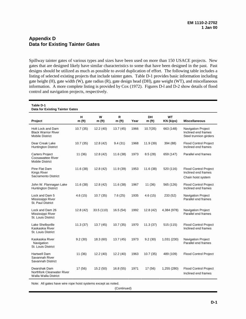
EM 1110-2-27021 Jan 00
D-1
Appendix DData for Existing Tainter Gates
Spillway tainter gates of various types and sizes have been used on more than 150 USACE projects. Newgates that are designed likely have similar characteristics to some that have been designed in the past. Pastdesigns should be utilized as much as possible to avoid duplication of effort. The following table includes alisting of selected existing projects that include tainter gates. Table D-1 provides basic information includinggate height (H), gate width (W), gate radius (R), gate design head (DH), gate weight (WT), and miscellaneousinformation. A more complete listing is provided by Cox (1972). Figures D-l and D-2 show details of floodcontrol and navigation projects, respectively.
Table D-1Data for Existing Tainter Gates
ProjectH
m (ft)W
m (ft)R
m (ft) YearDH
m (ft)WT
KN (kips) Miscellaneous
Holt Lock and DamBlack Warrior RiverMobile District
10.7 (35) 12.2 (40) 13.7 (45) 1966 10.7(35) 663 (148) Navigation ProjectInclined end framesSteel trunnion girders
Dear Creak LakeHuntington District
10.7 (35) 12.8 (42) 9.4 (31) 1968 11.9 (39) 394 (88) Flood Control ProjectInclined end frames
Carters ProjectCoosawattee RiverMobile District
11 (36) 12.8 (42) 11.6 (38) 1973 8.5 (28) 659 (147) Parallel end frames
Pine Flat DamKings RiverSacramento District
11.6 (38) 12.8 (42) 11.9 (39) 1953 11.6 (38) 520 (116) Flood Control ProjectInclined end frames
Chain hoist system
John W. Flannagan LakeHuntington District
11.6 (38) 12.8 (42) 11.6 (38) 1967 11 (36) 565 (126) Flood Control ProjectInclined end frames
Lock and Dam 5Mississippi RiverSt. Paul District
4.6 (15) 10.7 (35) 7.6 (25) 1935 4.6 (15) 233 (52) Navigation ProjectParallel end frames
Lock and Dam 26Mississippi RiverSt. Louis District
12.8 (42) 33.5 (110) 16.5 (54) 1992 12.8 (42) 4,384 (978) Navigation ProjectParallel end frames
Lake ShelbyvilleKaskaskia RiverSt. Louis District
11.3 (37) 13.7 (45) 10.7 (35) 1970 11.3 (37) 515 (115) Flood Control ProjectInclined end frames
Kaskaskia River NavigationSt. Louis District
9.2 (30) 18.3 (60) 13.7 (45) 1973 9.2 (30) 1,031 (230) Navigation ProjectParallel end frames
Hartwell DamSavannah RiverSavannah District
11 (36) 12.2 (40) 12.2 (40) 1963 10.7 (35) 489 (109) Flood Control Project
Dwarshak DamNorthfork Clearwater RiverWalla Walla District
17 (56) 15.2 (50) 16.8 (55) 1971 17 (56) 1,255 (280) Flood Control Project
Inclined end frames
Note: All gates have wire rope hoist systems except as noted.
(Continued)
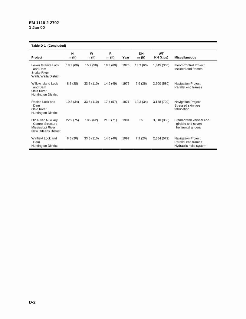
EM 1110-2-27021 Jan 00
D-2
Table D-1 (Concluded)
ProjectH
m (ft)W
m (ft)R
m (ft) YearDH
m (ft)WT
KN (kips) Miscellaneous
Lower Granite Lock and DamSnake RiverWalla Walla District
18.3 (60) 15.2 (50) 18.3 (60) 1975 18.3 (60) 1,345 (300) Flood Control ProjectInclined end frames
Willow Island Lock and DamOhio RiverHuntington District
8.5 (28) 33.5 (110) 14.9 (49) 1976 7.9 (26) 2,600 (580) Navigation ProjectParallel end frames
Racine Lock and DamOhio RiverHuntington District
10.3 (34) 33.5 (110) 17.4 (57) 1971 10.3 (34) 3,138 (700) Navigation ProjectStressed skin type fabrication
Old River Auxiliary Control StructureMississippi RiverNew Orleans District
22.9 (75) 18.9 (62) 21.6 (71) 1981 55 3,810 (850) Framed with vertical end girders and seven horizontal girders
Winfield Lock and DamHuntington District
8.5 (28) 33.5 (110) 14.6 (48) 1997 7.9 (26) 2,564 (572) Navigation ProjectParallel end framesHydraulic hoist system
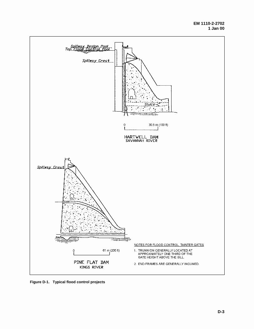
EM 1110-2-27021 Jan 00
D-3
Figure D-1. Typical flood control projects
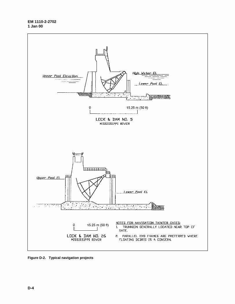
EM 1110-2-27021 Jan 00
D-4
Figure D-2. Typical navigation projects