design of microprocessor-based systemsprabal/teaching/eecs373-f10/slides/lec... · design of...
TRANSCRIPT
EECS 373Design of Microprocessor-Based Systems
Thomas SchmidUniversity of Michigan
Lecture 8: Timers: count, compare, capture, PWM
September 28, 2010
1http://home.netcom.com/~swansont/science.html

Minute Quiz...
2

Announcements
• Homework 1 posted on website– Due date October 7th
4
Where do we use time in an embedded system?
5
Why do we need accurate time?
• Scheduling of computation– Scheduler in operating systems– Real time operating systems
• Signal sampling– Audio sampling at 44.1 kHz– Sampling CCD at 30 fps
• Signal generation– 120 Hz TV refresh rate– Pulse Width Modulated (PWM) signals
• Communication– Media Access Control (MAC) protocols– Modulation
• Navigation– GPS
• Coordination6
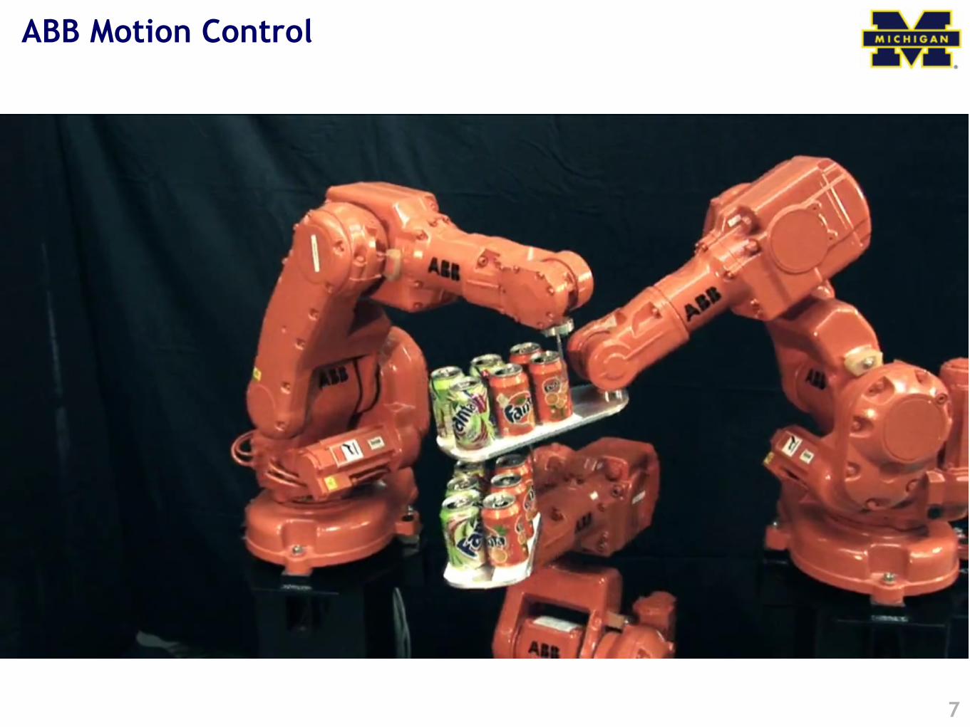
ABB Motion Control
7
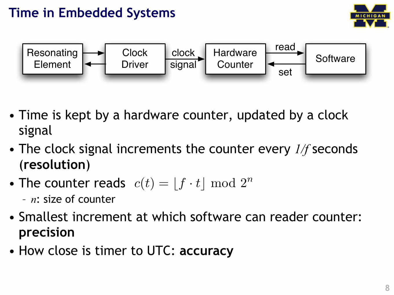
Time in Embedded Systems
• Time is kept by a hardware counter, updated by a clock signal
• The clock signal increments the counter every 1/f seconds (resolution)
• The counter reads – n: size of counter
• Smallest increment at which software can reader counter: precision
• How close is timer to UTC: accuracy
8
Resonating Element
Clock Driver
Hardware Counter
clocksignal
Softwareread
set
c(t) = �f · t� mod 2n
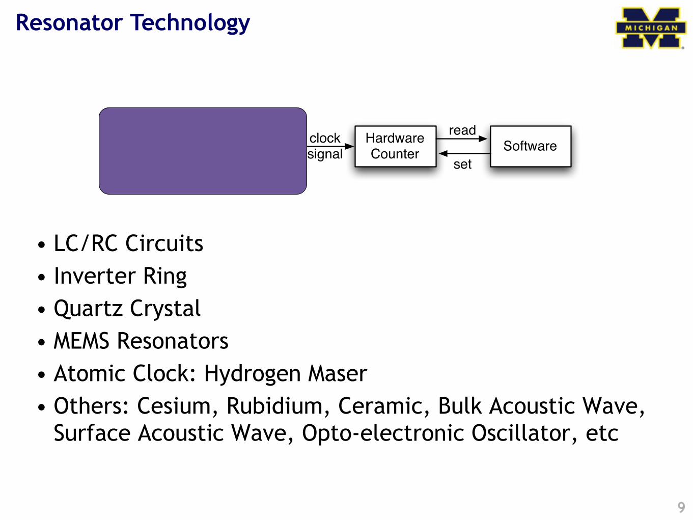
Resonator Technology
• LC/RC Circuits• Inverter Ring• Quartz Crystal• MEMS Resonators• Atomic Clock: Hydrogen Maser• Others: Cesium, Rubidium, Ceramic, Bulk Acoustic Wave,
Surface Acoustic Wave, Opto-electronic Oscillator, etc
9
Resonating Element
Clock Driver
Hardware Counter
clocksignal
Softwareread
set
Resonator As Filter
10
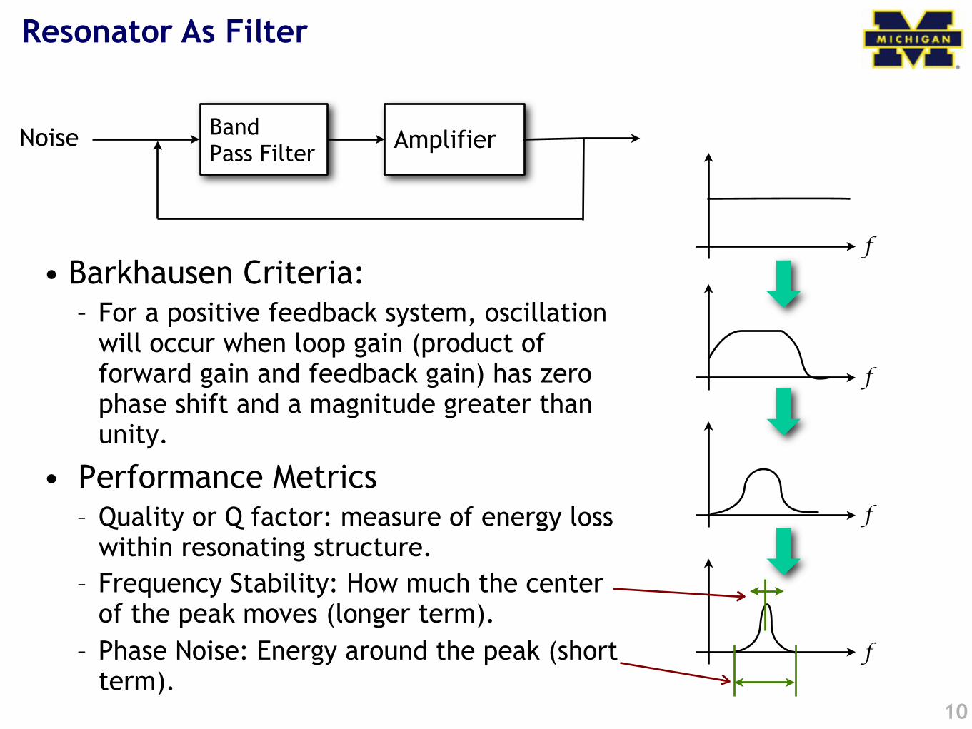
• Barkhausen Criteria: – For a positive feedback system, oscillation
will occur when loop gain (product of forward gain and feedback gain) has zero phase shift and a magnitude greater than unity.
• Performance Metrics– Quality or Q factor: measure of energy loss
within resonating structure.– Frequency Stability: How much the center
of the peak moves (longer term).– Phase Noise: Energy around the peak (short
term).
BandPass Filter AmplifierNoise
f
f
f
f
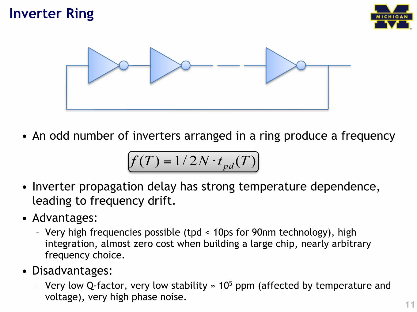
Inverter Ring
• An odd number of inverters arranged in a ring produce a frequency
• Inverter propagation delay has strong temperature dependence, leading to frequency drift.
• Advantages:– Very high frequencies possible (tpd < 10ps for 90nm technology), high
integration, almost zero cost when building a large chip, nearly arbitrary frequency choice.
• Disadvantages: – Very low Q-factor, very low stability ! 105 ppm (affected by temperature and
voltage), very high phase noise.11
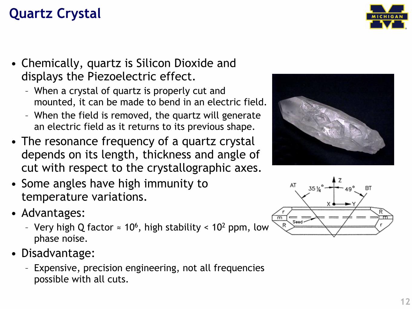
• Chemically, quartz is Silicon Dioxide and displays the Piezoelectric effect.– When a crystal of quartz is properly cut and
mounted, it can be made to bend in an electric field. – When the field is removed, the quartz will generate
an electric field as it returns to its previous shape.
• The resonance frequency of a quartz crystal depends on its length, thickness and angle of cut with respect to the crystallographic axes.
• Some angles have high immunity to temperature variations.
• Advantages:– Very high Q factor ! 106, high stability < 102 ppm, low
phase noise.
• Disadvantage:– Expensive, precision engineering, not all frequencies
possible with all cuts.
Quartz Crystal
12
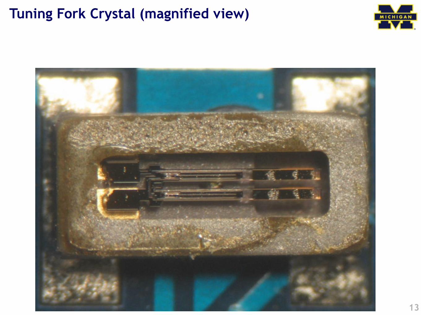
Tuning Fork Crystal (magnified view)
13
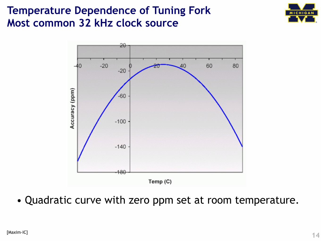
Temperature Dependence of Tuning ForkMost common 32 kHz clock source
• Quadratic curve with zero ppm set at room temperature.
14[Maxim-IC]
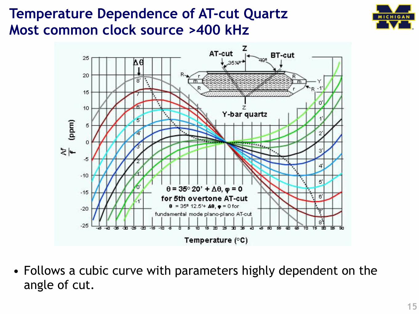
Temperature Dependence of AT-cut QuartzMost common clock source >400 kHz
• Follows a cubic curve with parameters highly dependent on the angle of cut.
15
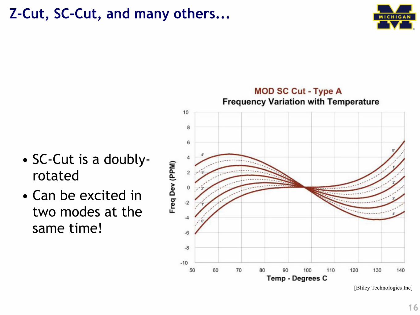
Z-Cut, SC-Cut, and many others...
• SC-Cut is a doubly-rotated
• Can be excited in two modes at the same time!
16
[Bliley Technologies Inc]
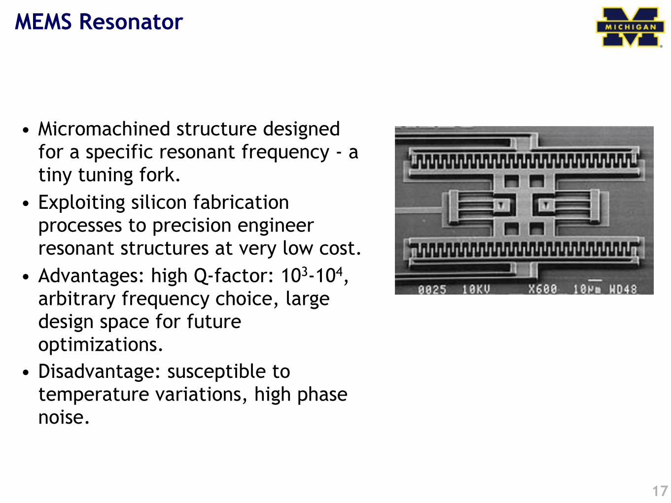
MEMS Resonator
• Micromachined structure designed for a specific resonant frequency - a tiny tuning fork.
• Exploiting silicon fabrication processes to precision engineer resonant structures at very low cost.
• Advantages: high Q-factor: 103-104, arbitrary frequency choice, large design space for future optimizations.
• Disadvantage: susceptible to temperature variations, high phase noise.
17
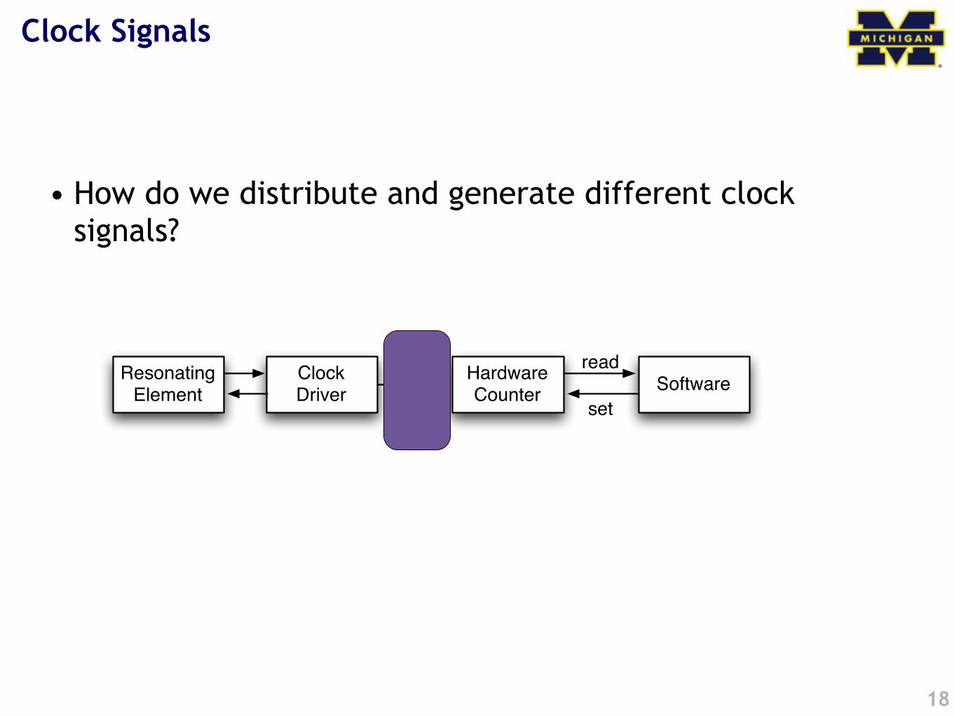
Clock Signals
• How do we distribute and generate different clock signals?
18
Resonating Element
Clock Driver
Hardware Counter
clocksignal
Softwareread
set
Revision 0 15
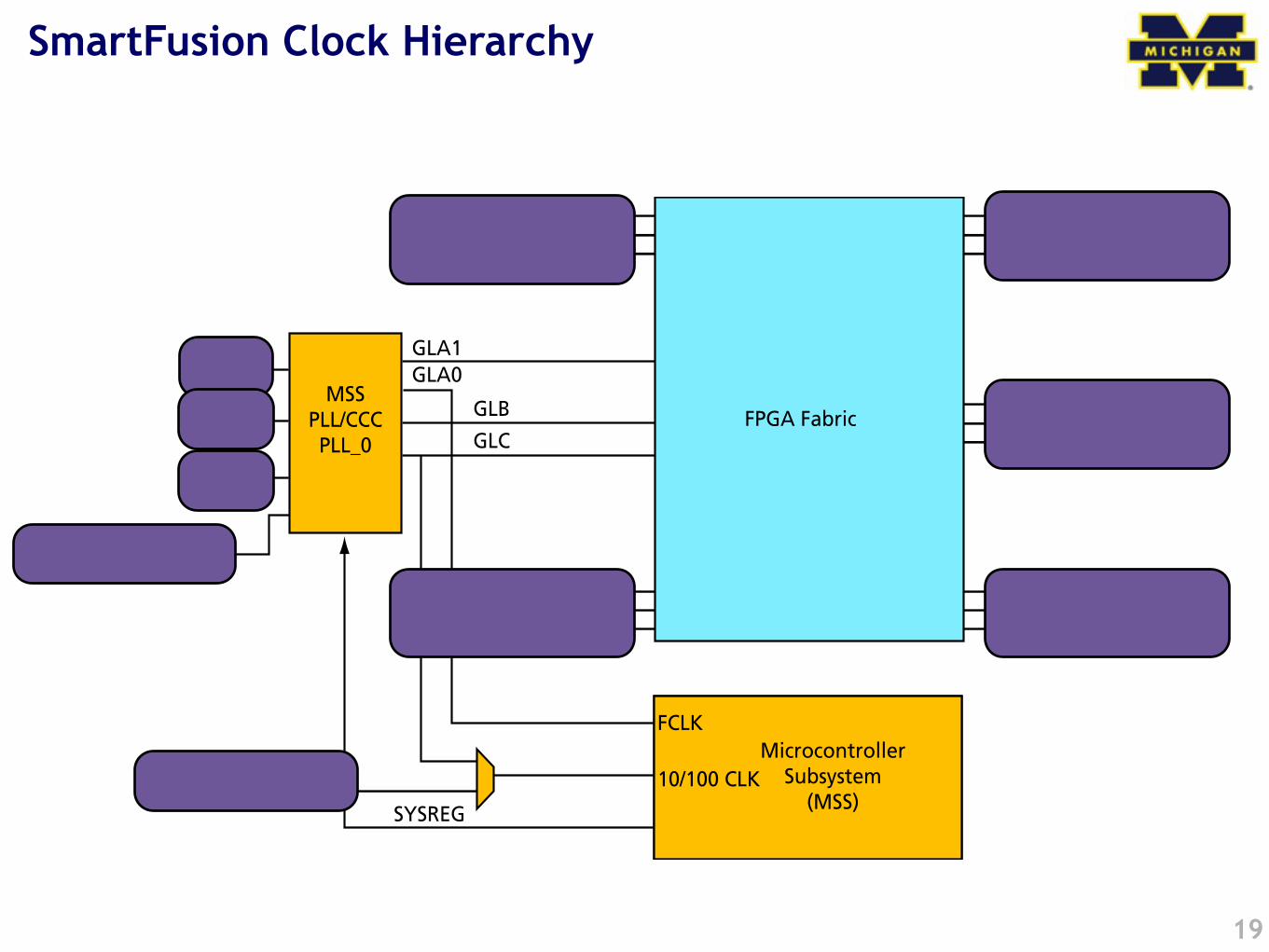
2 – Clocking Resources Available to the SmartFusion FPGA Fabric
IntroductionThis section describes the clocking resources available to the SmartFusion™ FPGA fabric. Some ofthe resources are embedded within the SmartFusion microcontroller subsystem (MSS), but providethe FPGA fabric with access to internal and external clock signals.The SmartFusion device family has a robust collection of clocking peripherals, some of which areshared between the SmartFusion FPGA fabric and the microcontroller subsystem.Figure 2-1 provides a top-level representation of the clocking resources available to theSmartFusion FPGA fabric. As shown in Figure 2-1, there is an MSS clock conditioning circuit (CCC)that contains a PLL. This MSS CCC is primarily configured via firmware running on the ARM®
Cortex™-M3 processor and is shared between the MSS and FPGA fabric. Users have the option ofusing Actel's Libero® Integrated Design Environment (IDE) MSS configurator to configure the MSSCCC and Actel System Boot Firmware. Alternatively, users can create custom firmware to setup theMSS CCC Configuration Registers. For more information about configuring the MSS clockingresources, refer to the "PLLs, Clock Conditioning Circuitry, and On-Chip Crystal Oscillators" sectionof the SmartFusion Microcontroller Subsystem User’s Guide. Additionally, there are five standardCCCs dedicated to the FPGA fabric. In the A2F200 device, the standard CCCs do not integrate a PLL.
Figure 2-1 • SmartFusion Device Clocking Resources
External 10/100 CLK
CCC
CCC
CCC
CCC
CCC
Global I/O Buffer Global I/O Buffer
Global I/O Buffer
Global I/O BufferGlobal I/O Buffer
Global I/O Buffer
FPGA Fabric
FCLK
10/100 CLKMicrocontroller
Subsystem(MSS)
GLA1GLA0
GLBGLC
32 KHzOsc.
MainOsc.
RCOsc.
MSSPLL/CCCPLL_0
SYSREG
SmartFusion Clock Hierarchy
19
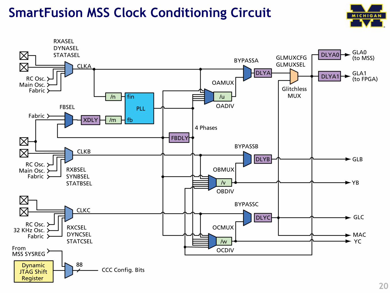
SmartFusion MSS Clock Conditioning Circuit
20
PLLs, Clock Conditioning Circuitry, and On-Chip Crystal Oscillators
110 Revision 1
The GLA0 output of the MSS_CCC block drives the input clock to the microcontroller subsystem(MSS). The clock source for the 10/100 Ethernet MAC can be sourced from an external pin or theGLC output of the MSS_CCC block, and the GLA1 and GLB outputs are dedicated to the FPGAfabric.As depicted in Figure 8-2, the MSS_CCC block consists of the following main components: inputclock multiplexers, PLL, dividers and delays. There are three main paths through the MSS_CCCblock: the CLKA, CLKB, and the CLKC paths, which output clocks onto the global buffers GLA, GLB,and GLC. As can be seen in more detail in Figure 8-3, there are actually two more outputs from thePLL/CCC block. The YB and YC outputs can drive additional local routing resources in the FPGAfabric. Figure 8-6 depicts a simplified view of the CCC blocks without a PLL.
Figure 8-2 • Simplified View of MSS_CCC Block
Figure 8-3 • SmartFusion MSS_CCC Block
Input Clock
Multiplexers PLL Dividers Delays
CLKA Inputs
CLKB Inputs
CLKC Inputs
GLA Outputs
GLB Outputs
GLC Outputs
/n
/m
/u
PLL
fin
fb
Fabric
4 Phases
DLYA
/v
DLYB
FBDLY
/w
DLYC
RC Osc.Main Osc.
Fabric
RC Osc.Main Osc.
Fabric
RC Osc.32 KHz Osc.
GLA0(to MSS)
GLB
GLC
GlitchlessMUX
DynamicJTAG ShiftRegister
88CCC Config. Bits
FromMSS SYSREG
DLYA0
GLA1(to FPGA)DLYA1
MAC
CLKA
FBSEL
CLKC
XDLYFabric
YB
YC
RXASELDYNASELSTATASEL
RXBSELSYNBSELSTATBSEL
RXCSELDYNCSELSTATCSEL
OCMUX
OBMUX
OAMUX
BYPASSA
BYPASSB
BYPASSC
GLMUXCFGGLMUXSEL
OADIV
OBDIV
OCDIV
CLKB
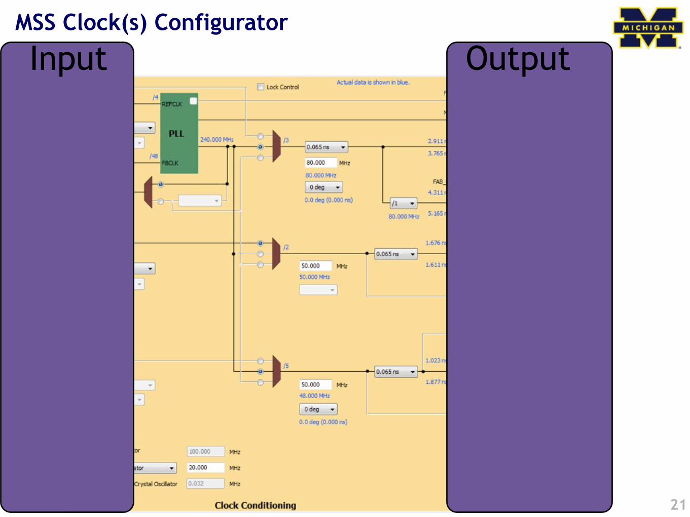
MSS Clock(s) Configurator
21
Input Output
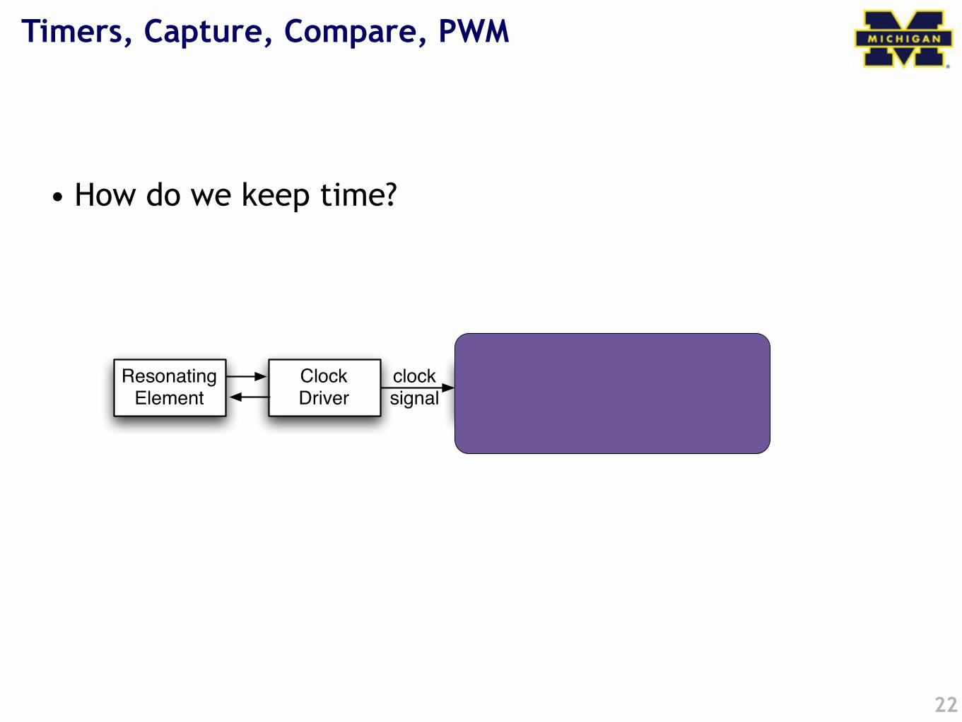
Timers, Capture, Compare, PWM
• How do we keep time?
22
Resonating Element
Clock Driver
Hardware Counter
clocksignal
Softwareread
set
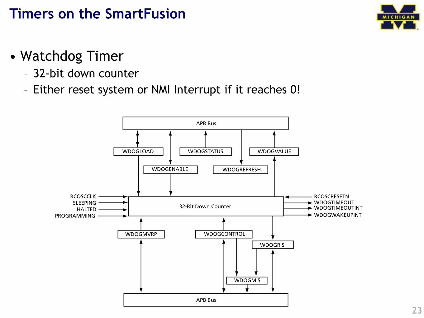
Timers on the SmartFusion
• Watchdog Timer– 32-bit down counter– Either reset system or NMI Interrupt if it reaches 0!
23
Revision 1 163
11 – Watchdog Timer
The Watchdog timer is an advanced peripheral bus (APB) slave that guards against system crashesby requiring that it is regularly serviced by the ARM® Cortex™-M3 processor or by a processor inthe FPGA fabric. It is likely that the most common use model will be one where the Watchdog isserviced by the Cortex-M3.
Watchdog Block DiagramFigure 11-1 shows the block diagram for the Watchdog timer.
Functional DescriptionThe operation of the Watchdog is based on a 32-bit down counter that must be refreshed atregular intervals by the Cortex-M3 or by a fabric-based processor. If the counter is not refreshed, itwill timeout and either cause a system reset or generate an interrupt to the processor, dependingon the value of a control bit. In normal operation, the generation of a reset or timeout interrupt bythe Watchdog does not occur because the Watchdog counter is refreshed on a regular basis.The 32-bit counter in the Watchdog is clocked with the 100 MHz RC oscillator output.On power-up of the device, the Watchdog is enabled with the timeout period set to approximately5.37 seconds.
Figure 11-1 • Watchdog Block Diagram
APB Bus
WDOGREFRESH
WDOGLOAD
32-Bit Down Counter
WDOGMVRP
APB Bus
WDOGENABLE
WDOGSTATUS WDOGVALUE
WDOGCONTROL
WDOGRIS
WDOGMIS
RCOSCCLKSLEEPING
HALTEDPROGRAMMING
RCOSCRESETNWDOGTIMEOUTWDOGTIMEOUTINTWDOGWAKEUPINT
Timers on the SmartFusion (2)
• SysTick Timer– ARM requires every Cortex-M3 to have this timer– Essentially a 24-bit down-counter to generate system ticks– Has its own interrupt– Clocked by FCLK with optional programmable divider
• See Actel SmartFusion MSS User Guide for register definitions
24
Timers on the SmartFusion (3)
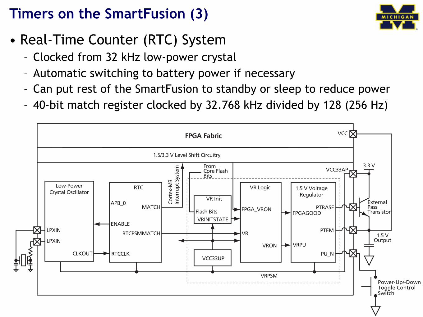
• Real-Time Counter (RTC) System– Clocked from 32 kHz low-power crystal– Automatic switching to battery power if necessary– Can put rest of the SmartFusion to standby or sleep to reduce power– 40-bit match register clocked by 32.768 kHz divided by 128 (256 Hz)
25
Revision 1 295
16 – Real-Time Counter (RTC) System
The real-time counter (RTC) system enables SmartFusion™ devices to support both standby andsleep modes of operation, greatly reducing power consumption in many applications. The RTCsystem comprises the following four blocks that work together to provide this increasedfunctionality and reduced power consumption:
• RTC • Low-power 32 KHz crystal oscillator• Battery switching circuit• MSS interface
Figure 16-1 shows these blocks and how they are connected.
Low-Power Crystal Oscillator Functional DescriptionThe low-power crystal oscillator generates a 32.768 KHz clock for the RTC. It consists of an invertingamplifier, an external ceramic or quartz resonator, and two load capacitors. The generated clock isalso connected to the microcontroller subsystem clock conditioning circuit (MSS_CCC) so that thisclock can be used by the FPGA fabric. This clock may also be used by the MSS. This oscillator is enabled/disabled by the XTAL_EN bit (bit 0) of the RTC's control/status register(CTRL_STAT_REG).
Figure 16-1 • Real-Time Counter System Block Diagram
RTC
Cort
ex-M
3In
terr
upt S
yste
m
RTCCLK
RTCPSMMATCH
ENABLE
MATCH
Low-PowerCrystal Oscillator
LPXIN
LPXIN
CLKOUT
1.5 V VoltageRegulator
FPGA Fabric
VRPU
PTBASE
PTEM
VCC
VR Logic
VR Init
PU_N
APB_0
VRINITSTATE
VRON
VR
Flash Bits
VRPSM
FPGAGOOD
Power-Up/-DownToggle ControlSwitch
1.5 VOutput
ExternalPassTransistor
3.3 V
1.5/3.3 V Level Shift Circuitry
FPGA_VRON
VCC33UP
VCC33APFromCore FlashBits
Timers on the SmartFusion (4)
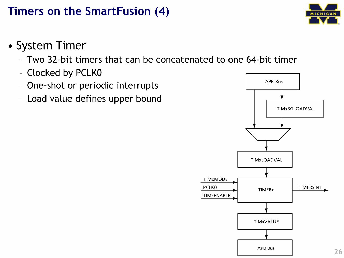
• System Timer– Two 32-bit timers that can be concatenated to one 64-bit timer– Clocked by PCLK0– One-shot or periodic interrupts– Load value defines upper bound
26
Revision 1 301
17 – System Timer
IntroductionThe System Timer consists of two programmable 32-bit decrementing counters that generateinterrupts to the ARM® Cortex™-M3 and FPGA fabric. Each counter has two possible modes ofoperation: Periodic mode or One-Shot mode. The two timers can be concatenated to create a64-bit timer with Periodic and One-Shot modes. The two 32-bit timers are identical. The letter "x"in register descriptions is used as a placeholder for 1 or 2, indicating Timer 1 or Timer 2.
Figure 17-1 • Block Diagram 32-Bit Mode
TIMERx
TIMxLOADVAL
TIMxBGLOADVAL
TIMxVALUE
APB Bus
TIMxENABLE
TIMERxINT
TIMxMODE
PCLK0
APB Bus
Interaction with the Outside World?
• Capture– Safe the time when a specific event happened, and signal an interrupt
• Compare– Generate an interrupt when counter reaches a specific value– Can set/reset/toggle a GPIO when counter reaches a specific value
• Pulse Width Modulated signal (PWM)– Special case of Compare– Set I/O when reaching a specific counter value– Clear I/O when reaching LOAD value– Usually used in continuous mode
• The SmartFusion is NOT a typical embedded MCU• None of the timers has capabilities to interface with the
outside world• BUT: we have the FPGA fabric
27
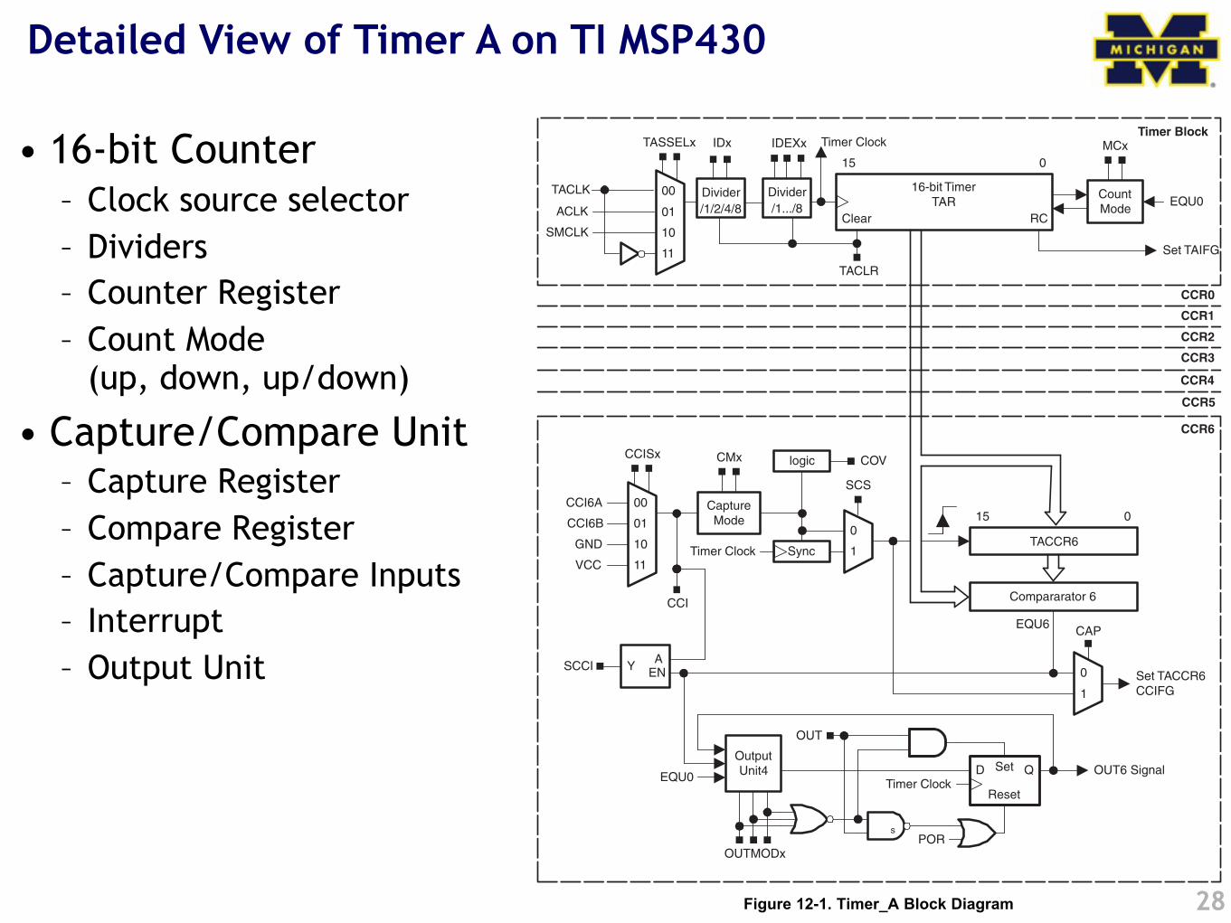
Detailed View of Timer A on TI MSP430
• 16-bit Counter– Clock source selector– Dividers– Counter Register– Count Mode
(up, down, up/down)
• Capture/Compare Unit– Capture Register– Compare Register– Capture/Compare Inputs– Interrupt– Output Unit
28
CCR6
Compararator 6CCI
15 0
CCISx
OUTMODx
CaptureMode
CMx
Sync
SCS
COVlogic
OutputUnit4 D Set Q
EQU0
OUT
OUT6 Signal
Reset
GND
VCC
CCI6A
CCI6B
EQU6
Divider
/1/2/4/8CountMode
16-bit TimerTAR
RC
Set TAIFG
15 0
TASSELx MCxIDx
00
01
10
11
Clear
Timer Clock
EQU0
Timer Clock
Timer Clock
TACCR6
SCCI YA
EN
CCR1
POR
TACLR
CCR0
Timer Block
00
01
10
11
Set TACCR6CCIFG
CAP
1
0
1
0
CCR2
CCR3
ACLK
SMCLK
TACLK
IDEXx
Divider
/1.../8
CCR4
CCR5
s
12.2 Timer_A Operation
12.2.1 16-Bit Timer Counter
www.ti.com Timer_A Operation
Figure 12-1. Timer_A Block Diagram
The Timer_A module is configured with user software. The setup and operation of Timer_A is discussed inthe following sections.
The 16-bit timer/counter register, TAR, increments or decrements (depending on mode of operation) witheach rising edge of the clock signal. TAR can be read or written with software. Additionally, the timer cangenerate an interrupt when it overflows.
SLAU208–June 2008 Timer_A 337
Submit Documentation Feedback
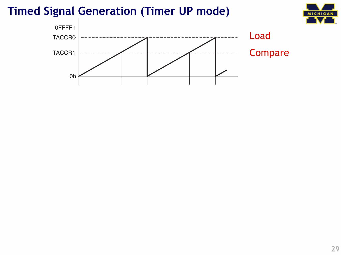
Timed Signal Generation (Timer UP mode)
29
Timer_A Operation
11-14 Timer_A
Output Example—Timer in Up Mode
The OUTx signal is changed when the timer counts up to the TACCRx value,and rolls from TACCR0 to zero, depending on the output mode. An exampleis shown in Figure 11−12 using TACCR0 and TACCR1.
Figure 11−12.Output Example—Timer in Up Mode
0h
0FFFFh
EQU0TAIFG
Output Mode 1: Set
Output Mode 2: Toggle/Reset
Output Mode 3: Set/Reset
Output Mode 4: Toggle
Output Mode 5: Reset
Output Mode 6: Toggle/Set
Output Mode 7: Reset/Set
TACCR0
TACCR1
EQU1 EQU0TAIFG
EQU1 EQU0TAIFG Interrupt Events
Load
Compare
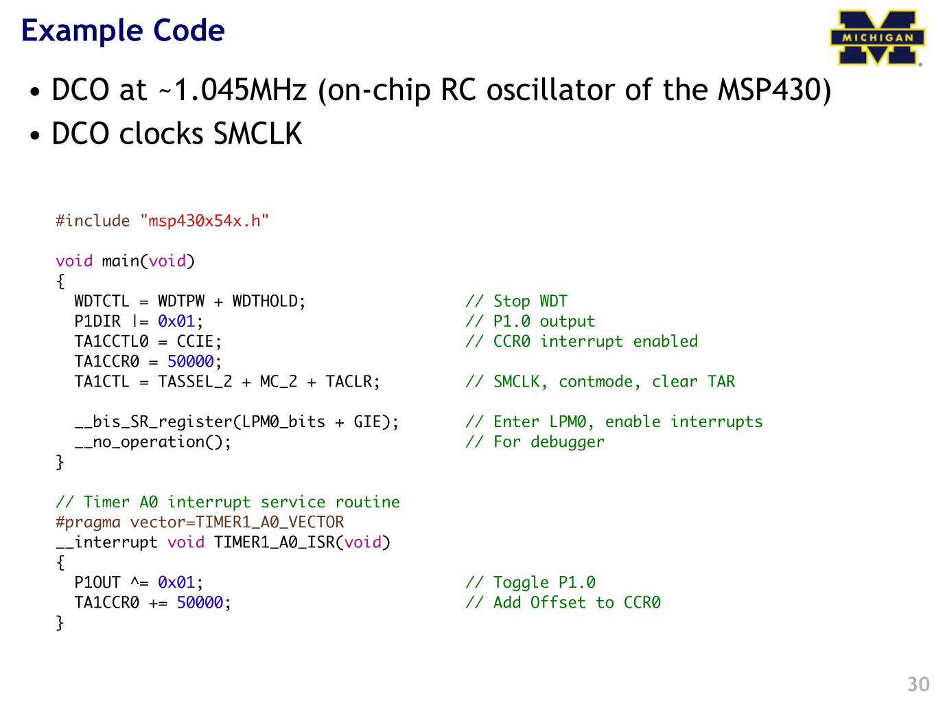
#include "msp430x54x.h"
void main(void){ WDTCTL = WDTPW + WDTHOLD; // Stop WDT P1DIR |= 0x01; // P1.0 output TA1CCTL0 = CCIE; // CCR0 interrupt enabled TA1CCR0 = 50000; TA1CTL = TASSEL_2 + MC_2 + TACLR; // SMCLK, contmode, clear TAR
__bis_SR_register(LPM0_bits + GIE); // Enter LPM0, enable interrupts __no_operation(); // For debugger}
// Timer A0 interrupt service routine#pragma vector=TIMER1_A0_VECTOR__interrupt void TIMER1_A0_ISR(void){ P1OUT ^= 0x01; // Toggle P1.0 TA1CCR0 += 50000; // Add Offset to CCR0}
Example Code
• DCO at ~1.045MHz (on-chip RC oscillator of the MSP430)• DCO clocks SMCLK
30
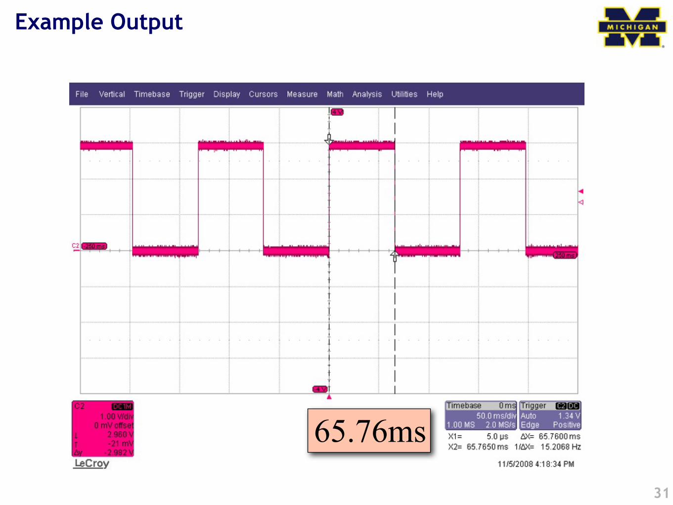
Example Output
31
65.76ms
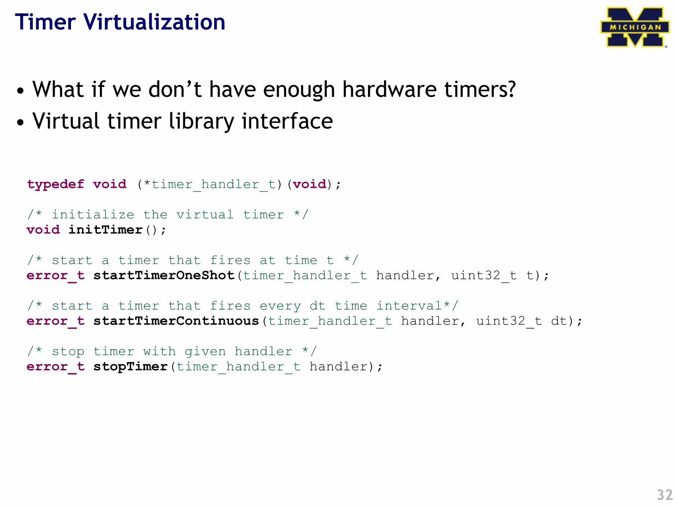
Timer Virtualization
• What if we don’t have enough hardware timers?• Virtual timer library interface
32
typedef void (*timer_handler_t)(void);
/* initialize the virtual timer */void initTimer();
/* start a timer that fires at time t */error_t startTimerOneShot(timer_handler_t handler, uint32_t t);
/* start a timer that fires every dt time interval*/error_t startTimerContinuous(timer_handler_t handler, uint32_t dt);
/* stop timer with given handler */error_t stopTimer(timer_handler_t handler);
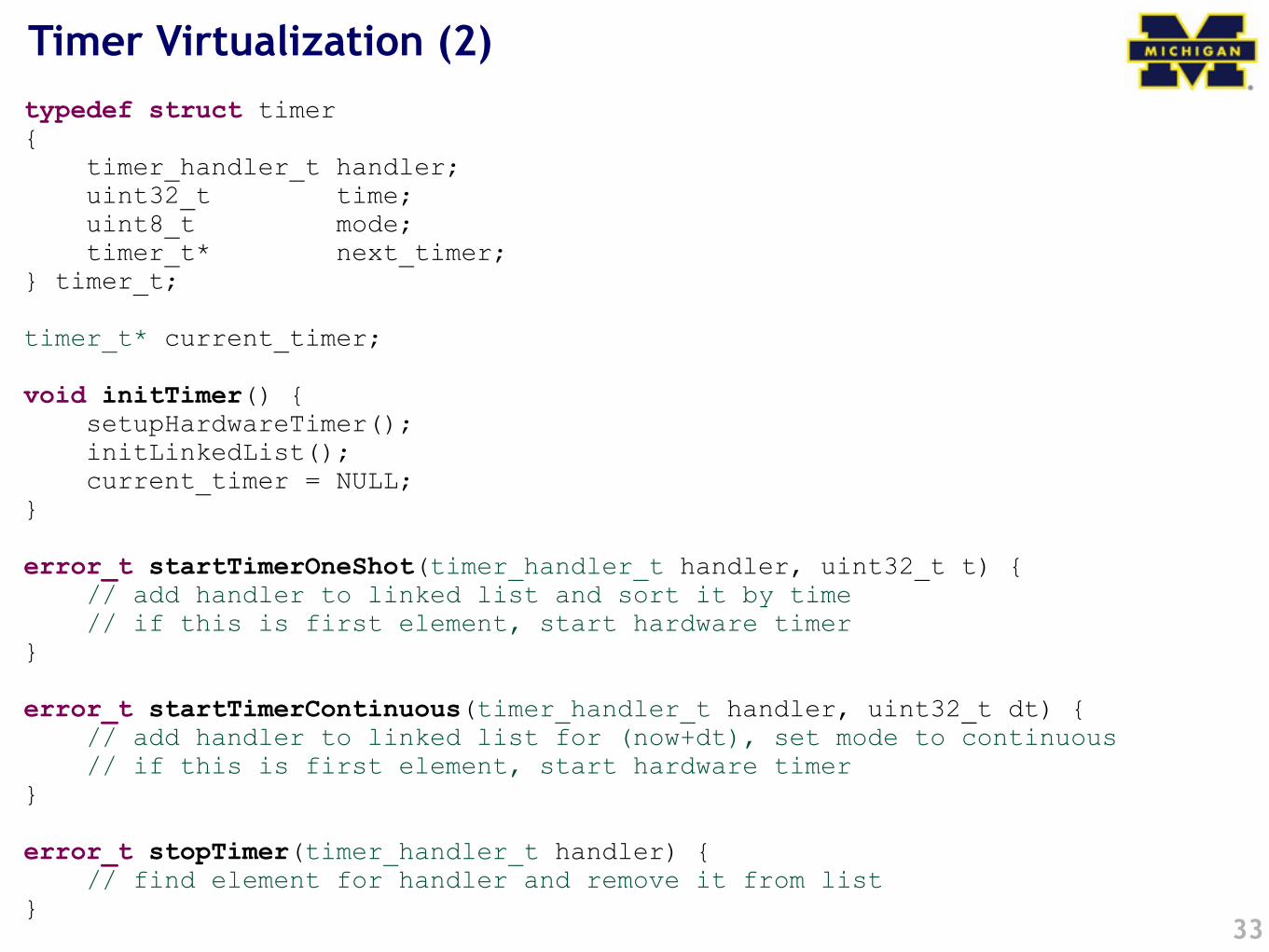
Timer Virtualization (2)
33
typedef struct timer{ timer_handler_t handler; uint32_t time; uint8_t mode; timer_t* next_timer;} timer_t;
timer_t* current_timer;
void initTimer() { setupHardwareTimer(); initLinkedList(); current_timer = NULL;}
error_t startTimerOneShot(timer_handler_t handler, uint32_t t) { // add handler to linked list and sort it by time // if this is first element, start hardware timer}
error_t startTimerContinuous(timer_handler_t handler, uint32_t dt) { // add handler to linked list for (now+dt), set mode to continuous // if this is first element, start hardware timer}
error_t stopTimer(timer_handler_t handler) { // find element for handler and remove it from list}
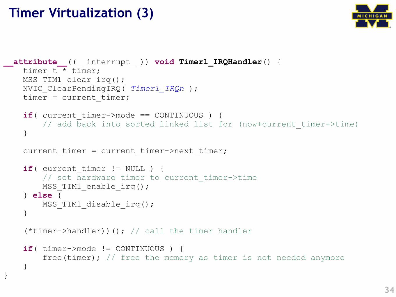
Timer Virtualization (3)
34
__attribute__((__interrupt__)) void Timer1_IRQHandler() { timer_t * timer; MSS_TIM1_clear_irq(); NVIC_ClearPendingIRQ( Timer1_IRQn ); timer = current_timer;
if( current_timer->mode == CONTINUOUS ) { // add back into sorted linked list for (now+current_timer->time) }
current_timer = current_timer->next_timer;
if( current_timer != NULL ) { // set hardware timer to current_timer->time MSS_TIM1_enable_irq(); } else { MSS_TIM1_disable_irq(); }
(*timer->handler))(); // call the timer handler
if( timer->mode != CONTINUOUS ) { free(timer); // free the memory as timer is not needed anymore }}
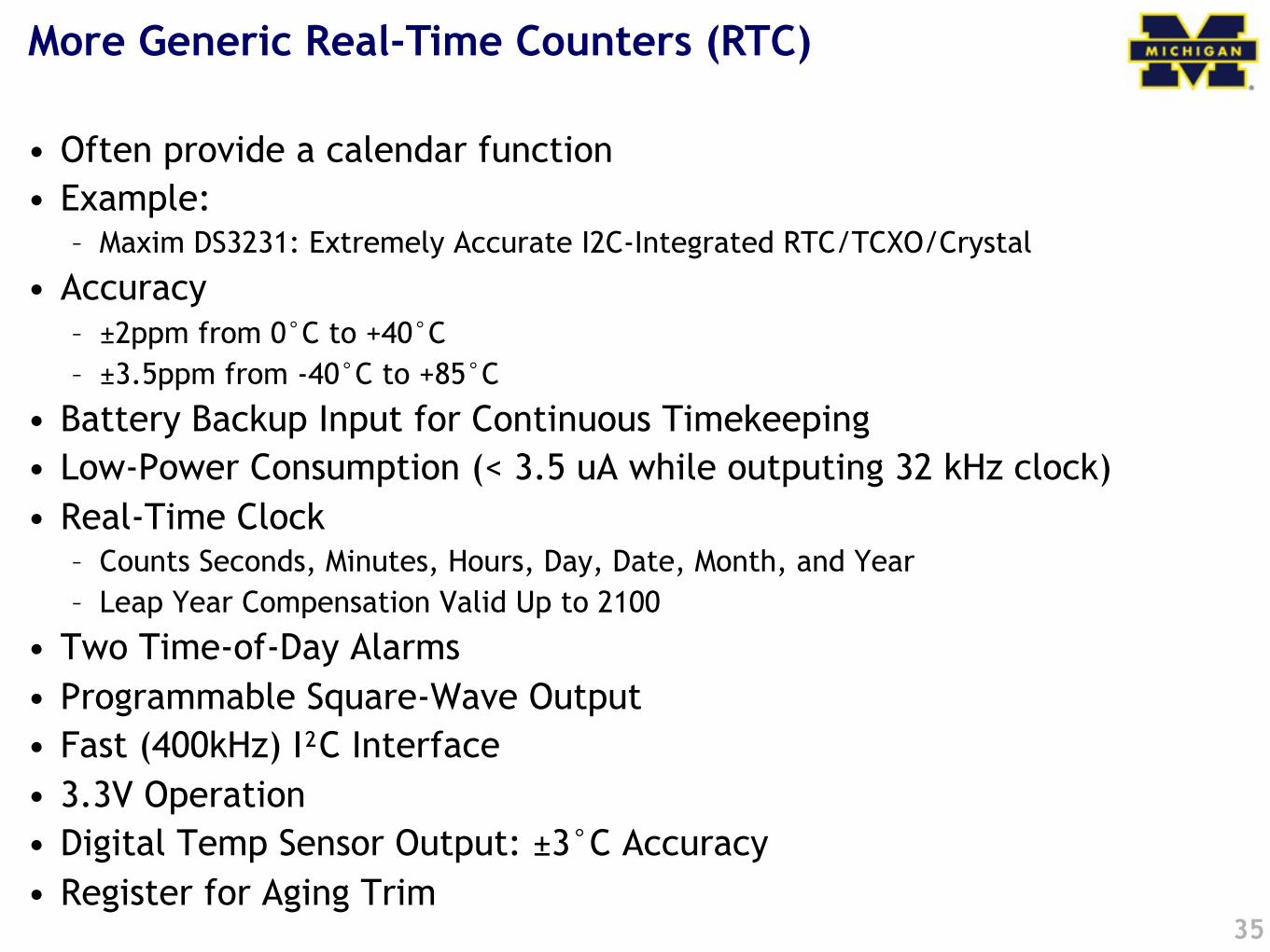
More Generic Real-Time Counters (RTC)
• Often provide a calendar function• Example:
– Maxim DS3231: Extremely Accurate I2C-Integrated RTC/TCXO/Crystal
• Accuracy– ±2ppm from 0°C to +40°C– ±3.5ppm from -40°C to +85°C
• Battery Backup Input for Continuous Timekeeping• Low-Power Consumption (< 3.5 uA while outputing 32 kHz clock)• Real-Time Clock
– Counts Seconds, Minutes, Hours, Day, Date, Month, and Year – Leap Year Compensation Valid Up to 2100
• Two Time-of-Day Alarms• Programmable Square-Wave Output• Fast (400kHz) I"C Interface• 3.3V Operation• Digital Temp Sensor Output: ±3°C Accuracy• Register for Aging Trim
35
Clock accuracy and stability
36
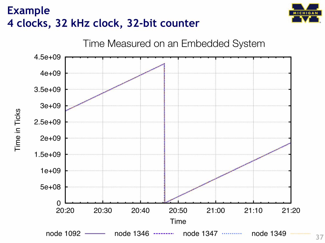
Example4 clocks, 32 kHz clock, 32-bit counter
37
0
5e+08
1e+09
1.5e+09
2e+09
2.5e+09
3e+09
3.5e+09
4e+09
4.5e+09
20:20 20:30 20:40 20:50 21:00 21:10 21:20
Tim
e in
Tic
ks
Time
Short Term Accuracy of FTSP, 300s Resync
node 1092 node 1346 node 1347 node 1349
Time Measured on an Embedded System
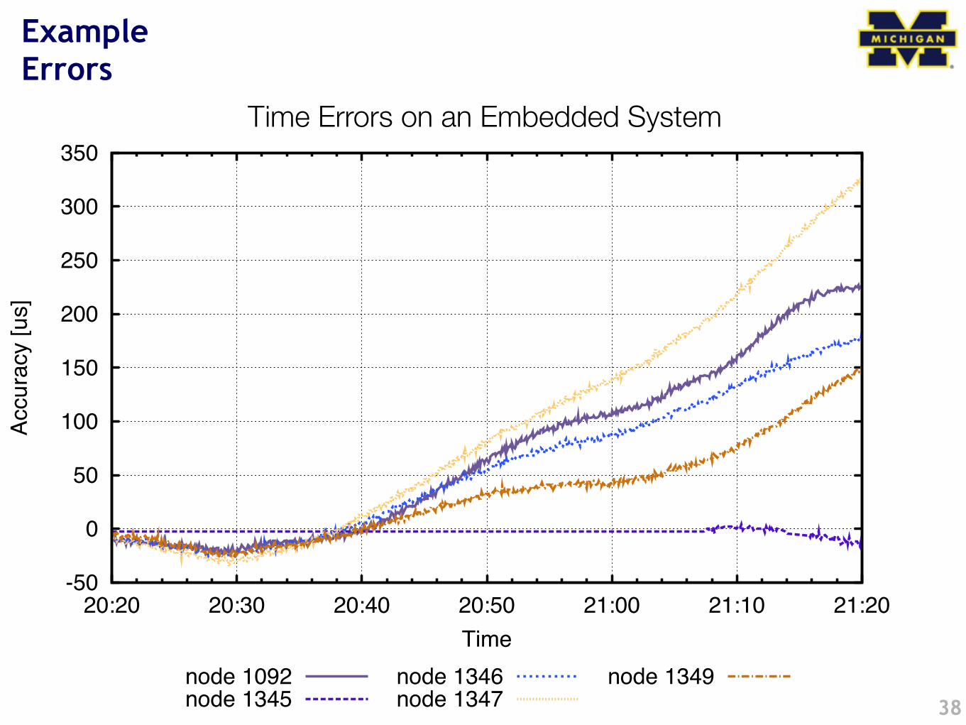
ExampleErrors
38
-50
0
50
100
150
200
250
300
350
20:20 20:30 20:40 20:50 21:00 21:10 21:20
Accu
racy [
us]
Time
Short Term Accuracy of FTSP, Resync Stopped
node 1092node 1345
node 1346node 1347
node 1349
Time Errors on an Embedded System
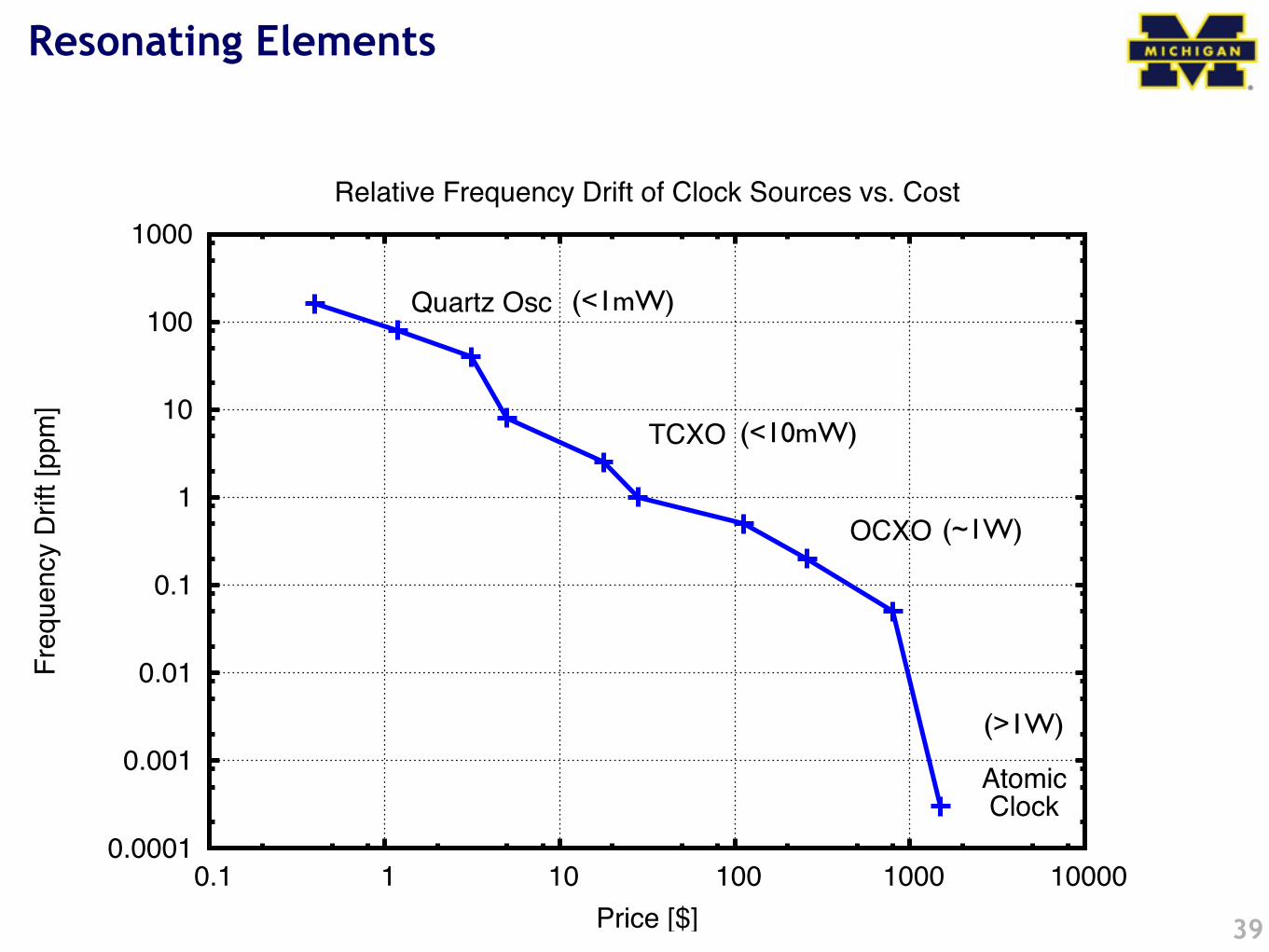
Resonating Elements
39
0.0001
0.001
0.01
0.1
1
10
100
1000
0.1 1 10 100 1000 10000
Freq
uenc
y Dr
ift [p
pm]
Price [$]
Relative Frequency Drift of Clock Sources vs. Cost
Quartz Osc
TCXO
OCXO
AtomicClock
(<1mW)
(<10mW)
(~1W)
(>1W)
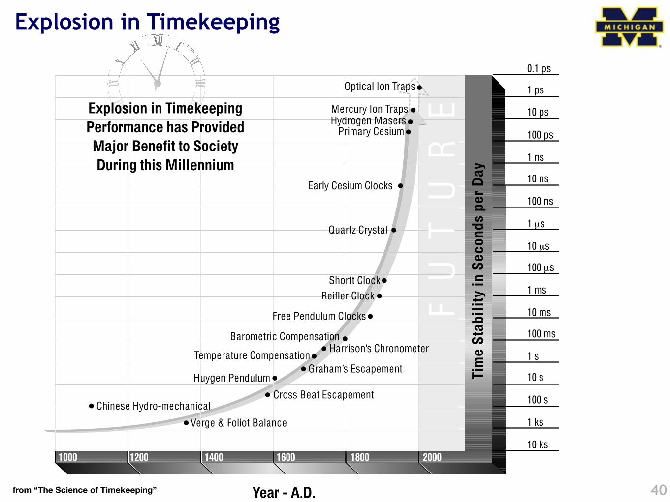
Explosion in Timekeeping
40from “The Science of Timekeeping”
51
The next-generation GNSS user market will be automotive as well asavionics. The accuracy requirements will be much more stringent —10 centimeters is one of the long-term goals. Light travels 10 cm in1/3 nanosecond. Methods have been proposed and are being studiedthat could accomplish these incredible goals for navigation and forclock synchronization among a set of orbiting satellites. Propagationdelay inaccuracies pose one of the biggest problems.
Finally, the issue of who controls the next-generation GNSS is complexand beyond the scope of this paper. We merely mention some of thechallenges ahead. Encryption of the signal would need agreement fromall parties owing to the global nature of the system. Ensuring a seam-less system will be difficult. And for safety-critical applications,responsibility and liability for the operation of the system is currentlyan active area of research [29].
10 ks
1 ks
100 s
10 s
1 s
100 ms
10 ms
1 ms
100 µs
10 µs
1 µs
100 ns
10 ns
1 ns
100 ps
10 ps
1 ps
0.1 ps
1000
Year - A.D.
1200 1400 1600 1800 2000
Verge & Foliot Balance
Cross Beat Escapement
Tim
e St
abil
ity in
Sec
onds
per
Day
Huygen PendulumGraham’s Escapement
Chinese Hydro-mechanical
Temperature CompensationHarrison’s Chronometer
Barometric Compensation
Free Pendulum Clocks
Reifler ClockShortt Clock
Quartz Crystal
Early Cesium Clocks
Primary Cesium Hydrogen Masers Mercury Ion Traps
Optical Ion Traps
Explosion in Timekeeping Performance has Provided
Major Benefit to Society During this Millennium
FU
TU
RE
A short history of time
41
Time
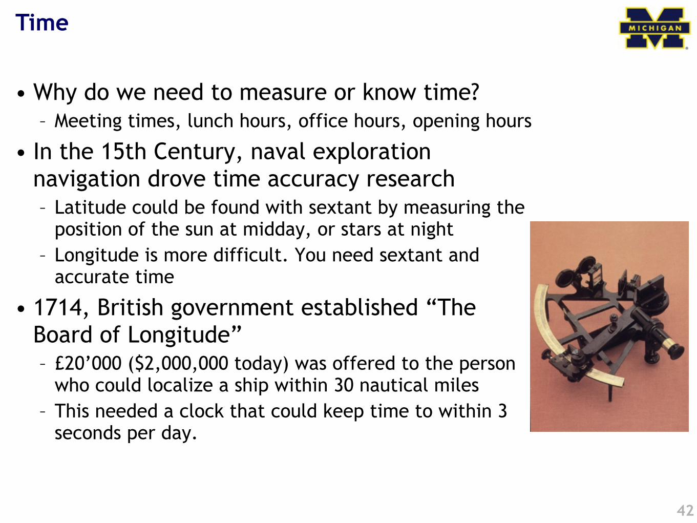
• Why do we need to measure or know time?– Meeting times, lunch hours, office hours, opening hours
• In the 15th Century, naval exploration navigation drove time accuracy research– Latitude could be found with sextant by measuring the
position of the sun at midday, or stars at night– Longitude is more difficult. You need sextant and
accurate time
• 1714, British government established “The Board of Longitude”– £20’000 ($2,000,000 today) was offered to the person
who could localize a ship within 30 nautical miles– This needed a clock that could keep time to within 3
seconds per day.
42
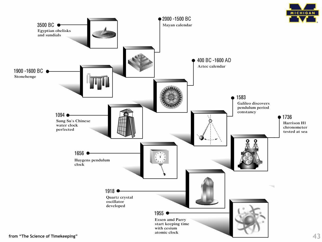
43
6
1656
400 BC -1600 AD
1900 -1600 BC
1094
3500 BC
1918
1964
1955
1583
2000 -1500 BC
Egyptian obelisksand sundials
Stonehenge
Aztec calendar
Sung Su’s Chinesewater clockperfected
Mayan calendar
Galileo discoverspendulum periodconstancy
Huygens pendulumclock
Essen amd Parrystart keeping timewith cesiumatomic clock
HP’s First CesiumClock (HP 5060A)introduced
Quartz crystaloscillatordeveloped
7
1978
1960
1736
1991
1997 to the Future
1993
1948-49
121
6
3
2
6
4
6
6
8
1110
Milestones in the Progressof Timekeeping
Lyons developsfirst atomic clock(ammonia)
HP 105B QuartzFrequencyStandardintroduced
Harrison H1chronometertested at sea
First GPS Block 1satellite launched
GPS declaredoperationaland HP 58503AGPS Time andFrequencyReceiverintroduced usingHP SmartClocktechnology
NAVSTAR Block 2R,next generation ofsatellites
HP 5071A PrimaryReference Standard(cesium) introduced
from “The Science of Timekeeping”
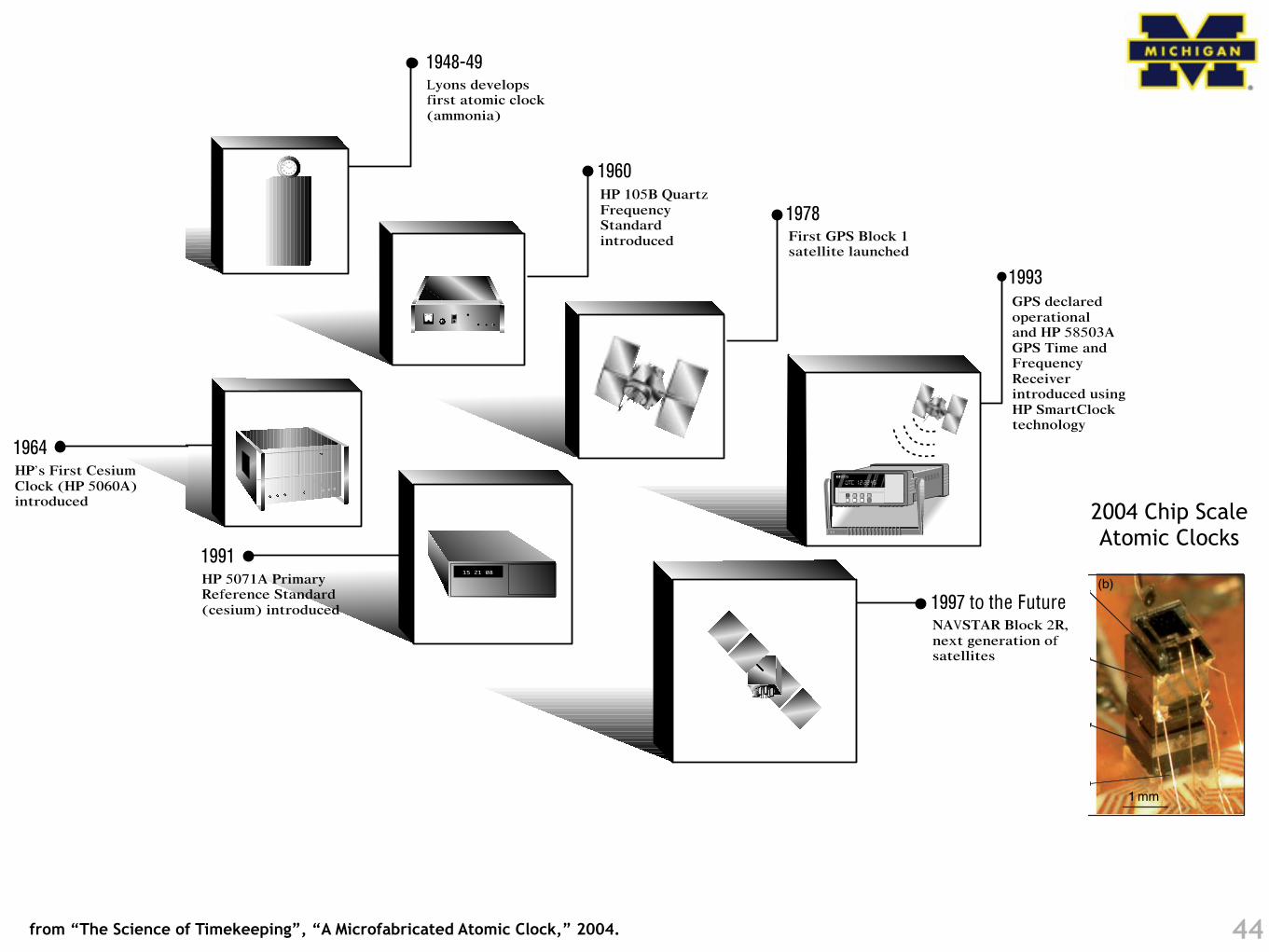
44from “The Science of Timekeeping”, “A Microfabricated Atomic Clock,” 2004.
7
1978
1960
1736
1991
1997 to the Future
1993
1948-49
121
6
3
2
6
4
6
6
8
1110
Milestones in the Progressof Timekeeping
Lyons developsfirst atomic clock(ammonia)
HP 105B QuartzFrequencyStandardintroduced
Harrison H1chronometertested at sea
First GPS Block 1satellite launched
GPS declaredoperationaland HP 58503AGPS Time andFrequencyReceiverintroduced usingHP SmartClocktechnology
NAVSTAR Block 2R,next generation ofsatellites
HP 5071A PrimaryReference Standard(cesium) introduced
6
1656
400 BC -1600 AD
1900 -1600 BC
1094
3500 BC
1918
1964
1955
1583
2000 -1500 BC
Egyptian obelisksand sundials
Stonehenge
Aztec calendar
Sung Su’s Chinesewater clockperfected
Mayan calendar
Galileo discoverspendulum periodconstancy
Huygens pendulumclock
Essen amd Parrystart keeping timewith cesiumatomic clock
HP’s First CesiumClock (HP 5060A)introduced
Quartz crystaloscillatordeveloped
Zeeman components, the atoms are pumped into acoherent dark state and the transmitted light isreduced. To stabilize the LO frequency onto thetop of the CPT resonance, its frequency is modulatedat a few kilohertz. Phase-sensitive detection of thetransmitted light at this frequency produces a disper-sive error signal that can be used to lock the LO tothe atomic resonance. A similar technique of phase-sensitive detection is used to lock the laser wave-length onto the center of the optical absorption bymodulating the laser current at a low frequency. It isimportant that both of these modulation frequenciesused for locking are well separated to avoid cross-talkbetween both loops. In addition to the two fre-quency-lock loops, two temperature servo loops arerequired to stabilize cell and laser temperatures. Insome designs, the laser and the cell are in goodthermal contact and one of the four feedback loopsis eliminated (Lutwak et al. 2004).
3.18.2.2 Physics Package
3.18.2.2.1 IntroductionThe physics package takes the instable 3.4-GHz sig-nal from the LO and compares it with the internalfrequency of the atoms. It generates an output signalthat determines how much the LO frequency differsfrom the internal frequency of the atoms. In order tominiaturize a MEMS clock, various approaches havebeen investigated. Most of these, however, includethe same general components and differ mostly in theengineered design. The first microfabricated physicspackage was reported in 2004 by the NationalInstitute of Standards and Technology (NIST)(Knappe et al. 2004b). A picture is shown in
Figure 8. It consisted of the VCSEL at the bottom,a micro-optical assembly, a vapor cell between twoheaters, and a photodiode on the top. The electricalinterconnects were wire bonds from the componentsin the stack to the pads on the baseplate.
In this approach, all the components were planarand in principle can be fabricated as arrays on indi-vidual wafers. While currently the wafers are dicedfirst and the components stacked afterward, thedesign potentially allows for assembling the wafersfirst prior to dicing them into many individual phy-sics packages, as indicated in Figure 9. This enablessimple exchange of components and will potentiallyreduce fabrication costs.
Other groups have taken more complex approa-ches, where the laser beam is not just passed in astraight line to the photodetector. Lutwak et al.
Laser Alkali cell
Lens /4
B
PD
Localoscillator
Physics package
3.4 GHzControl
electronics
DC tuning
HeaterHeater
Laser frequency
LO frequency
Cell temperatureLaser temperature
Figure 7 Schematic of a chip-scale atomic clock (CSAC) consisting of a local oscillator (LO), a physics package, andcontrol electronics. The physics package consists of a laser with heater, lens, a quarter waveplate (!/4), a vapor cell withheater, a magnetic offset field (B), and a photodetector (PD). The control electronics consist of servo loops for laser and celltemperature, as well as laser and LO frequency.
1 mm
(a) (b)
(f)
(e)
(d)
(c)
Figure 8 (a) Schematic and (b) photograph of a chip-scaleatomic clock (CSAC) physics package consisting of (c) avertical-cavity surface-emitting lasers (VCSEL), (d) an opticspackage, (e) a vapor cell with heaters, and (f) a photodetector.
MEMS Atomic Clocks 579
vol. 3, pp.571-612Comprehensive Microsystems,
2004 Chip Scale Atomic Clocks
Time Fundamentals
• The most accurate measurement to humans is the second
• 1s = Time a cesium atom needs for 9,192,631,770 state transitions at 0°K
• Most accurate clocks can keep time to ±0.3ns, equivalent to ±1 second in 10 million years
• Many other measurements are defined from the second– “The length of the path travelled by light in vacuum during a time
interval of 1/299,792,458 of a second (17th CGP, 1983, Resolution 1)”
• International Time Standard: UTC (Coordinated Universal Time)– UTC is based on the International Atomic Time (TAI) with leap seconds
added
– TAI is a weighted average of about 300 atomic clocks
45