design of frequency demodulator using goertzel...
TRANSCRIPT
ISSN: 2278 – 909X
International Journal of Advanced Research in Electronics and Communication Engineering (IJARECE)
Volume 6, Issue 7, July 2017
680
All Rights Reserved © 2017 IJARECE
Design of Frequency Demodulator Using
Goertzel Algorithm
Rahul Shetty, Pavanalaxmi
Abstract— Far distance Communication between millions
without a modulation is worthless, and Frequency modulation
has many advantages. Frequency modulation with adequate
data transfer capacity gives favorable position in crossing out
actual happening noise. This project deals with the design of
FM demodulator which includes FFT and Goertzel
Demodulators using Xilinx system generator design. Xilinx
system generator, a tool for Matlab environment plays a big
role in implementing signal processing instead on DSP
processors. This tool gives a programming HDL code and thus
bit stream can be effortlessly produced. In this Thesis, a novel
attempt is made to design reusable Goertzel blocks are
designed for performing FM demodulation and its
performance is evaluated with a typical Goertzel algorithm
based system as well as with a system designed using FFT. The
proposed system is designed using MATLAB Simulink, Xilinx
Block sets and system generator, which enables model-based programming approach.
Index Terms— Communication, Demodulation, FFT,
Goertzel, Processors, Simulation.
I. INTRODUCTION
Demodulators plays an important role in the field of digital
signal processing and communications and hence it is used
in various applications like Biomedical signal processing,
digital spectral analysis for speech recognition, imaging and
pattern recognition as well as signal manipulation using
filters, Data compression, instrumentation, machine
Inspection, terrestrial, axon prediction and multimedia,
wireless communication systems, microwave, satellite,
radio-over-fiber(RoF), distribution antenna and radar
systems, software-defined radio and many more
applications.
Amplitude, Frequency and phase are different kinds of
modulation techniques available in communication systems.
In this research Thesis, we motivated to do on FM
techniques because it has better fidelity and noise immunity
over AM. Slope Detector, Balanced Slope Detector, Foster-
Seeley Phase Discriminator, Ratio Detector are direct
methods and Phase Lock Loop is an indirect method for FM
demodulation. Fast Fourier Transform (FFT) and Goertzel
algorithm is approached in this Thesis for Demodulation of
FM signals.
Modulation is defined as the process by which some
characteristics; usually amplitude, frequency or phase, of a
carrier wave varies in accordance with the instantaneous
value of modulating signal, or Modulation is a process of
superimposing a low frequency signal on a high frequency
carrier signal. The systems used to perform modulation are
called as modulators and are considered as the most vital
block of any communication system. Communication
Systems employing these modulators are extensively used
in a large number of applications such as radar, aerospace,
naval/maritime communication, underwater communication,
mobile communication and many more. Out of all the
modulation techniques, frequency modulation (FM) is
widely used because of its many advantages and its
applications range from FM radio stations, on-board
systems for fighter aircrafts, satellites and many more
applications.
Nowadays, digital signal processing plays a vital role in
many real time applications in our day-to-day life and
frequency demodulation techniques are recognized as basic
elements needed for DSP. This provides a platform to
design an algorithm for digital signal processors (DSPs) and
Field Programmable Gate Arrays (FPGAs) based system
design. The invention of digital signal processors (DSPs)
and Field Programmable Gate Arrays (FPGAs) have
spearheaded way for novel digital signal processing
techniques and algorithms that are extremely used in large
number of applications.
A. Objective
In this paper, a reusable Goertzel blocks are designed for
performing FM demodulation and its performance is
evaluated with a typical Goertzel algorithm based system as
well as with a system designed using FFT. The proposed
system is designed using MATLAB Simulink, Xilinx Block
sets and system generator, which enables model-based
programming approach.
ISSN: 2278 – 909X
International Journal of Advanced Research in Electronics and Communication Engineering (IJARECE)
Volume 6, Issue 7, July 2017
681
All Rights Reserved © 2017 IJARECE
II. MATHEMATICAL ANALYSIS OF FM
DEMODULATOR
Modem with respect to FM mainly has Transmitter and
Receiver sections used to transmit and receive
modulated signal. Transmitter part mainly has desired
signal generator, Encoder, FM modulator and RF up-
converter. Receiver consists of a FM demodulator, a
decoder and decision logic.
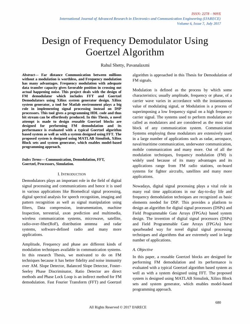
A. Frequency Modulation (FM)
Frequency modulation is one form of modulation
where the instantaneous frequency f i(t) is varied
linearly with the message signal m(t) and is given by
expression
fi t = fc + kfm(t) (1)
where, fc is carrier frequency, k f expressed in hertz's
per volt is frequency sensitivity of the modulator.
Frequency modulation wave form is shown in Fig 1.
Fig. 1. Waveform of FM signal
General form of expression for Modulator wave is
given as s(t)= Ac.cos[θ(t)] where Ac is carrier
amplitude which is maintained constant overall and
θ(t) is the angular argument which is varied
accordingly with the message signal m(t). So θ(t)
value will be 2πfc + 2πkf m t . dtt
0 Hence FM wave in
time domain can be expressed as
s(t)=Ac.cos[2πfc + 2πkf m t . dtt
0] (2)
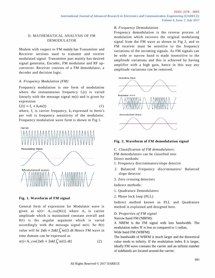
B. Frequency Demodulation
Frequency demodulation is the reverse process of
modulation which recovers the original modulating
signal from the FM wave as shown in Fig 2, and so
FM receiver must be sensitive to the frequency
variations of the incoming signals. As FM signals can
be wide or narrow band is made insensitive to the
amplitude variations and this is achieved by having
amplifier with a high gain, hence in this way any
amplitude variations can be removed.
Fig. 2. Waveform of FM demodulation signal
C. Classification of FM demodulators:
FM demodulators can be classified into
Direct methods:
1. Frequency discriminators/slope detector
2. Balanced Frequency discriminators/ Balanced
slope detector
3. Zero crossing detectors
Indirect methods:
1. Quadrature Demodulators
2. Phase lock loop (PLL)
Indirect method known as PLL and Quadrature
method is explained and designed here.
D. Properties of FM signal
Narrow band FM (NBFM):
A NBFM is the FM signal with less bandwidth. The
modulation index 'ß' is less as compared to 1 radian,
Wide band FM (WBFM):
The bandwidth of WBFM is much larger and the theoretical
value tends to infinity. If the modulation index ß is larger,
ideally FM wave contains the carrier and an infinite number
of sidebands are located around the carrier.
ISSN: 2278 – 909X
International Journal of Advanced Research in Electronics and Communication Engineering (IJARECE)
Volume 6, Issue 7, July 2017
682
All Rights Reserved © 2017 IJARECE
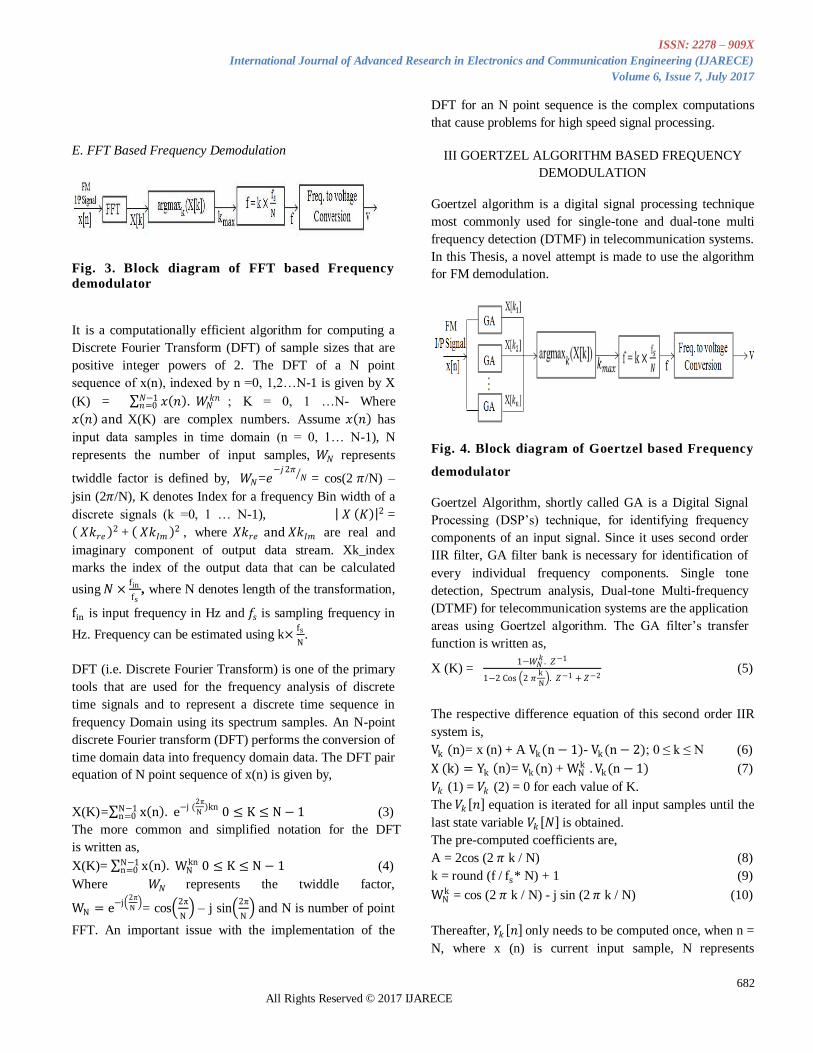
E. FFT Based Frequency Demodulation
Fig. 3. Block diagram of FFT based Frequency
demodulator
It is a computationally efficient algorithm for computing a
Discrete Fourier Transform (DFT) of sample sizes that are
positive integer powers of 2. The DFT of a N point
sequence of x(n), indexed by n =0, 1,2…N-1 is given by X
(K) = 𝑥 𝑛 . 𝑊𝑁𝑘𝑛𝑁−1
𝑛=0 ; K = 0, 1 …N- Where
𝑥 𝑛 and X(K) are complex numbers. Assume 𝑥 𝑛 has
input data samples in time domain (n = 0, 1… N-1), N
represents the number of input samples, 𝑊𝑁 represents
twiddle factor is defined by, 𝑊𝑁=𝑒−𝑗2𝜋
𝑁 = cos(2 𝜋/N) –
jsin (2𝜋/N), K denotes Index for a frequency Bin width of a
discrete signals (k =0, 1 … N-1), 𝑋 𝐾 2 =
𝑋𝑘𝑟𝑒 2 + 𝑋𝑘𝐼𝑚 2 , where 𝑋𝑘𝑟𝑒 and 𝑋𝑘𝐼𝑚 are real and
imaginary component of output data stream. Xk_index
marks the index of the output data that can be calculated
using 𝑁 ×fin
fs, where N denotes length of the transformation,
fin is input frequency in Hz and 𝑓𝑠 is sampling frequency in
Hz. Frequency can be estimated using k×fs
N.
DFT (i.e. Discrete Fourier Transform) is one of the primary
tools that are used for the frequency analysis of discrete
time signals and to represent a discrete time sequence in
frequency Domain using its spectrum samples. An N-point
discrete Fourier transform (DFT) performs the conversion of
time domain data into frequency domain data. The DFT pair
equation of N point sequence of x(n) is given by,
X(K)= x n . e−j (2π
N)knN−1
n=0 0 ≤ K ≤ N − 1 (3)
The more common and simplified notation for the DFT
is written as,
X(K)= x n . WNknN−1
n=0 0 ≤ K ≤ N − 1 (4)
Where 𝑊𝑁 represents the twiddle factor,
WN = e−j
2π
N = cos
2π
N – j sin
2π
N and N is number of point
FFT. An important issue with the implementation of the
DFT for an N point sequence is the complex computations
that cause problems for high speed signal processing.
III GOERTZEL ALGORITHM BASED FREQUENCY
DEMODULATION
Goertzel algorithm is a digital signal processing technique
most commonly used for single-tone and dual-tone multi
frequency detection (DTMF) in telecommunication systems.
In this Thesis, a novel attempt is made to use the algorithm
for FM demodulation.
Fig. 4. Block diagram of Goertzel based Frequency
demodulator
Goertzel Algorithm, shortly called GA is a Digital Signal
Processing (DSP‟s) technique, for identifying frequency
components of an input signal. Since it uses second order
IIR filter, GA filter bank is necessary for identification of
every individual frequency components. Single tone
detection, Spectrum analysis, Dual-tone Multi-frequency
(DTMF) for telecommunication systems are the application
areas using Goertzel algorithm. The GA filter‟s transfer
function is written as,
X (K) = 1−𝑊𝑁
𝑘 . 𝑍−1
1−2 Cos 2 𝜋k
N . 𝑍−1 + 𝑍−2
(5)
The respective difference equation of this second order IIR
system is,
Vk (n)= x (n) + A Vk(n − 1)- Vk (n − 2); 0 ≤ k ≤ N (6)
X (k) = Yk n = Vk (n) + WNk . Vk(n − 1) (7)
𝑉𝑘 (1) = 𝑉𝑘 (2) = 0 for each value of K.
The 𝑉𝑘 𝑛 equation is iterated for all input samples until the
last state variable 𝑉𝑘 𝑁 is obtained.
The pre-computed coefficients are,
A = 2cos (2 𝜋 k / N) (8)
k = round (f / fs* N) + 1 (9)
WNk = cos (2 𝜋 k / N) - j sin (2 𝜋 k / N) (10)
Thereafter, 𝑌𝑘 𝑛 only needs to be computed once, when n =
N, where x (n) is current input sample, N represents
ISSN: 2278 – 909X
International Journal of Advanced Research in Electronics and Communication Engineering (IJARECE)
Volume 6, Issue 7, July 2017
683
All Rights Reserved © 2017 IJARECE
Goertzel Block Size is like the number of points in an
equivalent FFT, k represents frequency index of targeted
frequencies, f is targeted frequencies in Hz and fs is
sampling frequency in Hz. The Magnitude squared is given
as,
|X (K)|2 = |Yk (n) | = 𝑉𝑘2 (N) + 𝑉𝑘
2 (N-1) – 2cos (2 𝜋 k /
N)𝑉𝑘 (𝑁) . 𝑉𝑘 (N-1) (11)
Magnitude of X(K) is needed to decode the detected
frequencies. As N increases, 𝐕𝐤(𝐧 − 𝟏) and 𝐕𝐤(𝐧 − 𝟐)
and |𝐗 (𝐊)|𝟐 increases and also it takes longer time
for detecting the frequencies.
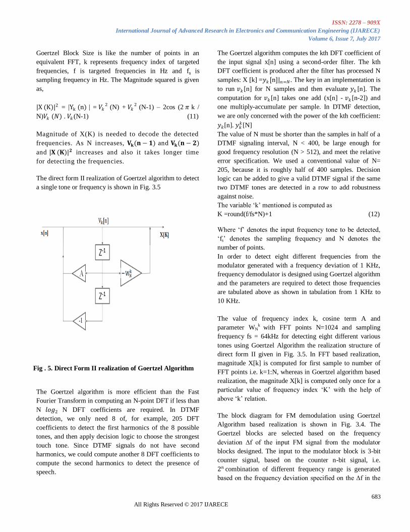
The direct form II realization of Goertzel algorithm to detect
a single tone or frequency is shown in Fig. 3.5
Fig . 5. Direct Form II realization of Goertzel Algorithm
The Goertzel algorithm is more efficient than the Fast
Fourier Transform in computing an N-point DFT if less than
N 𝑙𝑜𝑔2 N DFT coefficients are required. In DTMF
detection, we only need 8 of, for example, 205 DFT
coefficients to detect the first harmonics of the 8 possible
tones, and then apply decision logic to choose the strongest
touch tone. Since DTMF signals do not have second
harmonics, we could compute another 8 DFT coefficients to
compute the second harmonics to detect the presence of
speech.
The Goertzel algorithm computes the kth DFT coefficient of
the input signal x[n] using a second-order filter. The kth
DFT coefficient is produced after the filter has processed N
samples: X [k] =𝑦𝑘 [n]|𝑛=𝑁. The key in an implementation is
to run 𝑣𝑘 [n] for N samples and then evaluate 𝑦𝑘 [n]. The
computation for 𝑣𝑘 [n] takes one add (x[n] - 𝑣𝑘 [n-2]) and
one multiply-accumulate per sample. In DTMF detection,
we are only concerned with the power of the kth coefficient:
𝑦𝑘[n]. 𝑦𝑘𝑘[N]
The value of N must be shorter than the samples in half of a
DTMF signaling interval, N < 400, be large enough for
good frequency resolution (N > 512), and meet the relative
error specification. We used a conventional value of N=
205, because it is roughly half of 400 samples. Decision
logic can be added to give a valid DTMF signal if the same
two DTMF tones are detected in a row to add robustness
against noise.
The variable „k‟ mentioned is computed as
K =round(f/fs*N)+1 (12)
Where „f‟ denotes the input frequency tone to be detected,
„fs‟ denotes the sampling frequency and N denotes the
number of points.
In order to detect eight different frequencies from the
modulator generated with a frequency deviation of 1 KHz,
frequency demodulator is designed using Goertzel algorithm
and the parameters are required to detect those frequencies
are tabulated above as shown in tabulation from 1 KHz to
10 KHz.
The value of frequency index k, cosine term A and
parameter WNk with FFT points N=1024 and sampling
frequency fs = 64kHz for detecting eight different various
tones using Goertzel Algorithm the realization structure of
direct form II given in Fig. 3.5. In FFT based realization,
magnitude X[k] is computed for first sample to number of
FFT points i.e. k=1:N, whereas in Goertzel algorithm based
realization, the magnitude X[k] is computed only once for a
particular value of frequency index „K‟ with the help of
above „k‟ relation.
The block diagram for FM demodulation using Goertzel
Algorithm based realization is shown in Fig. 3.4. The
Goertzel blocks are selected based on the frequency
deviation ∆f of the input FM signal from the modulator
blocks designed. The input to the modulator block is 3-bit
counter signal, based on the counter n-bit signal, i.e.
2𝑛 combination of different frequency range is generated
based on the frequency deviation specified on the ∆f in the
ISSN: 2278 – 909X
International Journal of Advanced Research in Electronics and Communication Engineering (IJARECE)
Volume 6, Issue 7, July 2017
684
All Rights Reserved © 2017 IJARECE
modulator design. The magnitude X[k] from each Goertzel
block output is computed and the decision logic block
shown in Fig. 3.4 is used to find argmaxkX(k), which is in
turn used to find the frequency of the input FM signal and
the output voltage is generated accordingly. An alternative
architecture to the one shown in Fig. 3.5 is given in Fig. 3.4
wherein the same Goertzel block is reused to detect different
frequencies and it is designed with the motive of reducing
hardware resources on increasing the number of frequencies
to be detected.
A. Applications of FFT Algorithm
Spectrum Analyzer for on-board satellite communication
systems requires FFT to compute frequency spectrum of an
input signals.
A.1 Advantages
It is the faster version of DFT; it can be applied to the
number of samples in the signal is power of two. The
number of complex multiplier is greatly reduced in FFT in
the order of 𝑁
2𝑙𝑜𝑔2 N from N 𝑙𝑜𝑔2 N in DFT.More
Computation time is required for sweeping all frequency
components to compute the specified frequency of interest.
Reordering of input signal i.e. Bit-Reversal order is required
to perform FFT. Complexity has increased on increasing the
transformation length.
B. Applications of Goertzel Algorithm
Goertzel Algorithm especially applicable in the field of
single tone and DTMF (Dual Tone Multi-frequency)
detection in touch-tone telephones to represent the digits
corresponding to the user push buttons as well as it is
suitable for computer applications such as voice mail,
telephone banking, pager systems, email application and
interactive control applications such as conference calling
and call forwarding.
B.1 Advantages of Goertzel Algorithm
Goertzel Algorithm is more suitable in DTMF applications
which require only few spectral components for detecting
frequencies instead of computing whole spectrum. In this
area, Goertzel Algorithm is significantly faster and also it
requires only few constants needs to compute. So, that it
saves computation time, reducing hardware complexity and
avoiding Complex algebra. Also, Goertzel Algorithm does
not require reordering of data in input and output side.
Frequency resolution can be achieved exactly for desired
input signals over FFT. Disadvantages of Goertzel
algorithm is frequency index can compute only for known
set of frequencies and not suitable for random noise input
signals for unknown frequencies.
IV IMPLEMENTATION OF FM MODULATOR IN
XSG
Xilinx system Generator block set integrated with
Matlab Simulink is used in this project for
implementation.
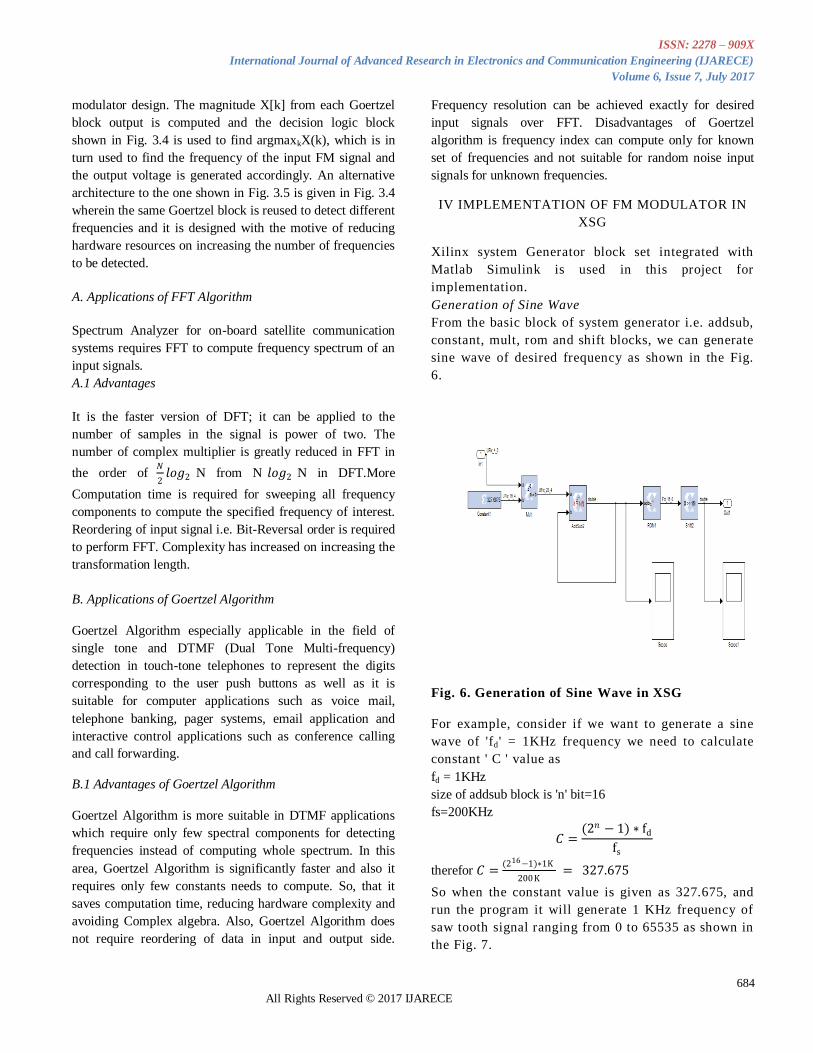
Generation of Sine Wave
From the basic block of system generator i.e. addsub,
constant, mult, rom and shift blocks, we can generate
sine wave of desired frequency as shown in the Fig.
6.
Fig. 6. Generation of Sine Wave in XSG
For example, consider if we want to generate a sine
wave of 'fd ' = 1KHz frequency we need to calculate
constant ' C ' value as
fd = 1KHz
size of addsub block is 'n' bit=16
fs=200KHz
𝐶 =(2𝑛 − 1) ∗ fd
fs
therefor 𝐶 =(216−1)∗1K
200K = 327.675
So when the constant value is given as 327.675, and
run the program it will generate 1 KHz frequency of
saw tooth signal ranging from 0 to 65535 as shown in
the Fig. 7.
ISSN: 2278 – 909X
International Journal of Advanced Research in Electronics and Communication Engineering (IJARECE)
Volume 6, Issue 7, July 2017
685
All Rights Reserved © 2017 IJARECE
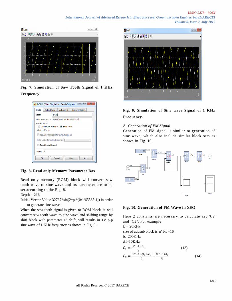
Fig. 7. Simulation of Saw Tooth Signal of 1 KHz
Frequency
Fig. 8. Read only Memory Parameter Box
Read only memory (ROM) block will convert saw
tooth wave to sine wave and its parameter are to be
set according to the Fig. 8.
Depth = 216
Initial Vector Value 32767*sin(2*pi*[0:1/65535:1]) in order
to generate sine wave
When the saw tooth signal is given to ROM block, it will
convert saw tooth wave to sine wave and shifting range by
shift block with parameter 15 shift, will results in 1V p-p
sine wave of 1 KHz frequency as shown in Fig. 9.
Fig. 9. Simulation of Sine wave Signal of 1 KHz
Frequency.
A. Generation of FM Signal
Generation of FM signal is similar to generation of
sine wave, which also include similar block sets as
shown in Fig. 10.
Fig. 10. Generation of FM Wave in XSG
Here 2 constants are necessary to calculate say 'C 1 '
and „C2‟. For example
fc = 20KHz
size of addsub block is 'n' bit =16
fs=200KHz
Δf=10KHz
𝐶1 =(2𝑛−1)∗fc
fs (13)
𝐶2 = 2𝑛−1 ∗(fc +∆ f)
fs−
(2𝑛−1)∗fd
fs (14)
ISSN: 2278 – 909X
International Journal of Advanced Research in Electronics and Communication Engineering (IJARECE)
Volume 6, Issue 7, July 2017
686
All Rights Reserved © 2017 IJARECE
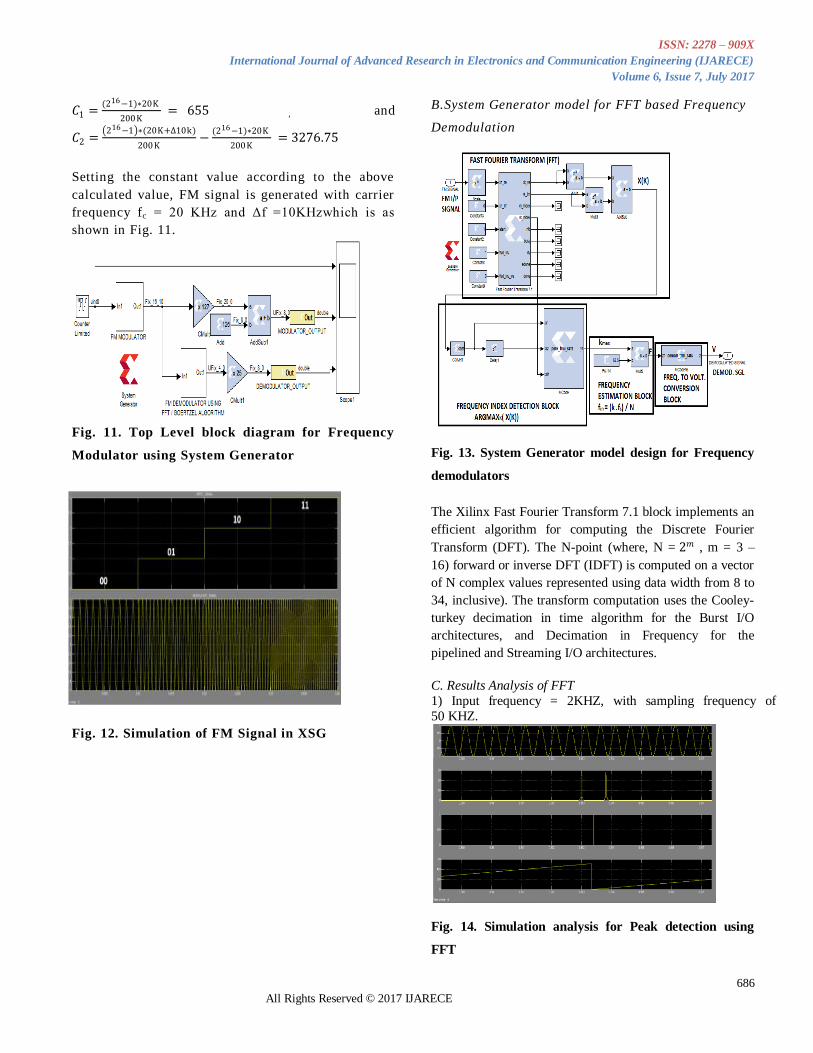
𝐶1 =(216−1)∗20K
200K = 655 , and
𝐶2 = 216−1 ∗(20K+∆10k)
200K−
(216−1)∗20K
200K = 3276.75
Setting the constant value according to the above
calculated value, FM signal is generated with carrier
frequency fc = 20 KHz and Δf =10KHzwhich is as
shown in Fig. 11.
Fig. 11. Top Level block diagram for Frequency
Modulator using System Generator
Fig. 12. Simulation of FM Signal in XSG
B.System Generator model for FFT based Frequency
Demodulation
Fig. 13. System Generator model design for Frequency
demodulators
The Xilinx Fast Fourier Transform 7.1 block implements an
efficient algorithm for computing the Discrete Fourier
Transform (DFT). The N-point (where, N = 2𝑚 , m = 3 –
16) forward or inverse DFT (IDFT) is computed on a vector
of N complex values represented using data width from 8 to
34, inclusive). The transform computation uses the Cooley-
turkey decimation in time algorithm for the Burst I/O
architectures, and Decimation in Frequency for the
pipelined and Streaming I/O architectures.
C. Results Analysis of FFT
1) Input frequency = 2KHZ, with sampling frequency of
50 KHZ.
Fig. 14. Simulation analysis for Peak detection using
FFT
ISSN: 2278 – 909X
International Journal of Advanced Research in Electronics and Communication Engineering (IJARECE)
Volume 6, Issue 7, July 2017
687
All Rights Reserved © 2017 IJARECE
Done pin at 0.9134 in x - axis, the difference between done pin
and next peak values of the FFT signal (0.9138 - 0.9134) is
0.0004
2) Input frequency = 2KHZ, with sampling frequency of 50
KHZ
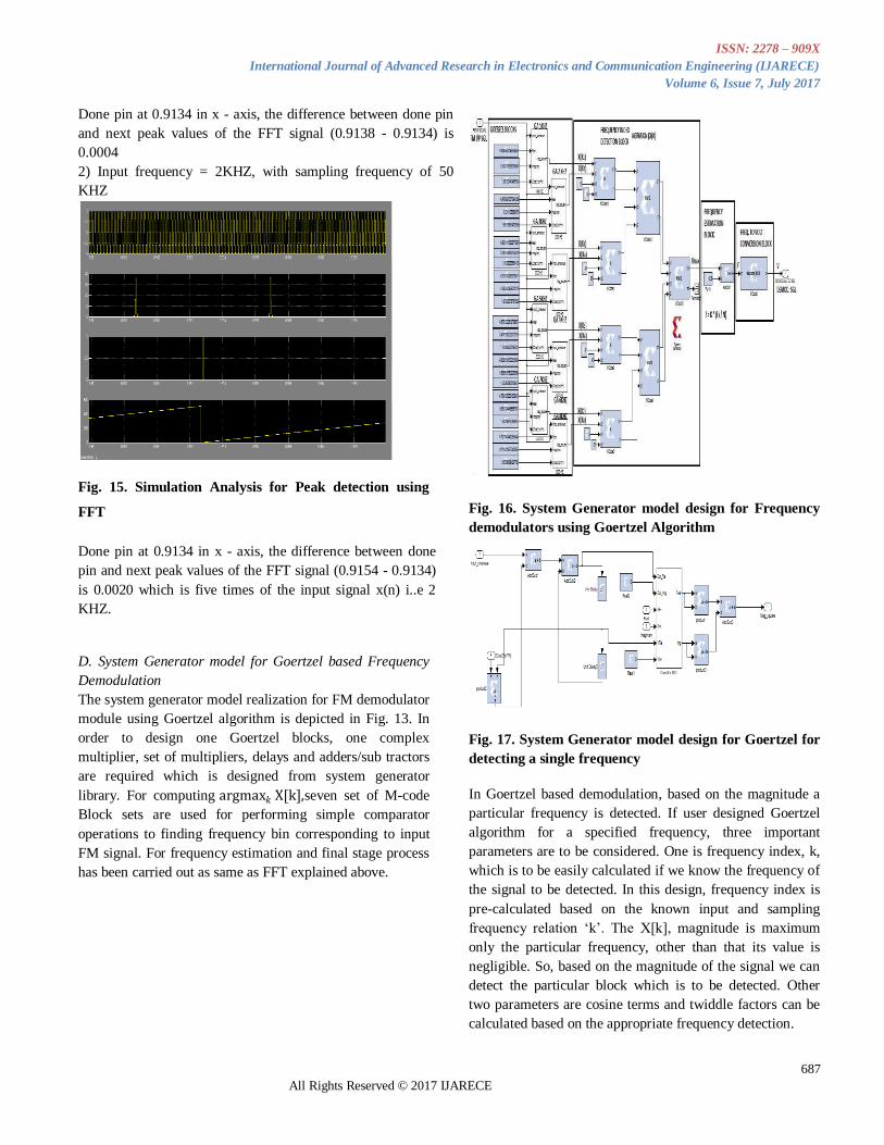
Fig. 15. Simulation Analysis for Peak detection using
FFT
Done pin at 0.9134 in x - axis, the difference between done
pin and next peak values of the FFT signal (0.9154 - 0.9134)
is 0.0020 which is five times of the input signal x(n) i..e 2
KHZ.
D. System Generator model for Goertzel based Frequency
Demodulation
The system generator model realization for FM demodulator
module using Goertzel algorithm is depicted in Fig. 13. In
order to design one Goertzel blocks, one complex
multiplier, set of multipliers, delays and adders/sub tractors
are required which is designed from system generator
library. For computing argmax𝑘 X[k],seven set of M-code
Block sets are used for performing simple comparator
operations to finding frequency bin corresponding to input
FM signal. For frequency estimation and final stage process
has been carried out as same as FFT explained above.
Fig. 16. System Generator model design for Frequency
demodulators using Goertzel Algorithm
Fig. 17. System Generator model design for Goertzel for
detecting a single frequency
In Goertzel based demodulation, based on the magnitude a
particular frequency is detected. If user designed Goertzel
algorithm for a specified frequency, three important
parameters are to be considered. One is frequency index, k,
which is to be easily calculated if we know the frequency of
the signal to be detected. In this design, frequency index is
pre-calculated based on the known input and sampling
frequency relation „k‟. The X[k], magnitude is maximum
only the particular frequency, other than that its value is
negligible. So, based on the magnitude of the signal we can
detect the particular block which is to be detected. Other
two parameters are cosine terms and twiddle factors can be
calculated based on the appropriate frequency detection.
ISSN: 2278 – 909X
International Journal of Advanced Research in Electronics and Communication Engineering (IJARECE)
Volume 6, Issue 7, July 2017
688
All Rights Reserved © 2017 IJARECE
In order to detect the frequencies, modulator is designed
using FM techniques. Based on the counter limited signal,
the number of frequencies is to be generated. The Goertzel
blocks are designed and coefficients are pre-computed to
detect various frequencies. Once if it is detected the
appropriate frequency index values are considered as output.
In this way, all the eight Goertzel blocks are detected one
after another and corresponding frequency index is chosen.
This logic is built using MATLAB M-code and it is
embedded into the Xilinx blocks using if-else condition.
After computing frequency index passing through self-built
M-code block and it is multiplied with 𝐹𝑠 / N, to compute
the frequency of the input signal to be detected. This process
is continuous for detecting eight different frequencies to be
detected. This can be extended to detect „N‟ number of
frequencies. The frequencies are converted back into full-
pledged demodulated signal.
V EXPERIMENTAL RESULTS
A. Simulation results for FFT based frequency
demodulation
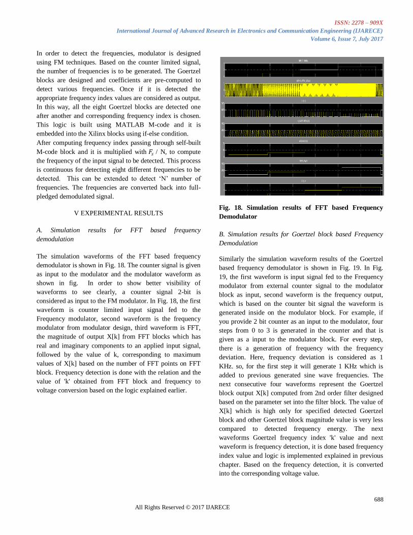
The simulation waveforms of the FFT based frequency
demodulator is shown in Fig. 18. The counter signal is given
as input to the modulator and the modulator waveform as
shown in fig. In order to show better visibility of
waveforms to see clearly, a counter signal 2-bit is
considered as input to the FM modulator. In Fig. 18, the first
waveform is counter limited input signal fed to the
Frequency modulator, second waveform is the frequency
modulator from modulator design, third waveform is FFT,
the magnitude of output X[k] from FFT blocks which has
real and imaginary components to an applied input signal,
followed by the value of k, corresponding to maximum
values of X[k] based on the number of FFT points on FFT
block. Frequency detection is done with the relation and the
value of 'k' obtained from FFT block and frequency to
voltage conversion based on the logic explained earlier.
Fig. 18. Simulation results of FFT based Frequency
Demodulator
B. Simulation results for Goertzel block based Frequency
Demodulation
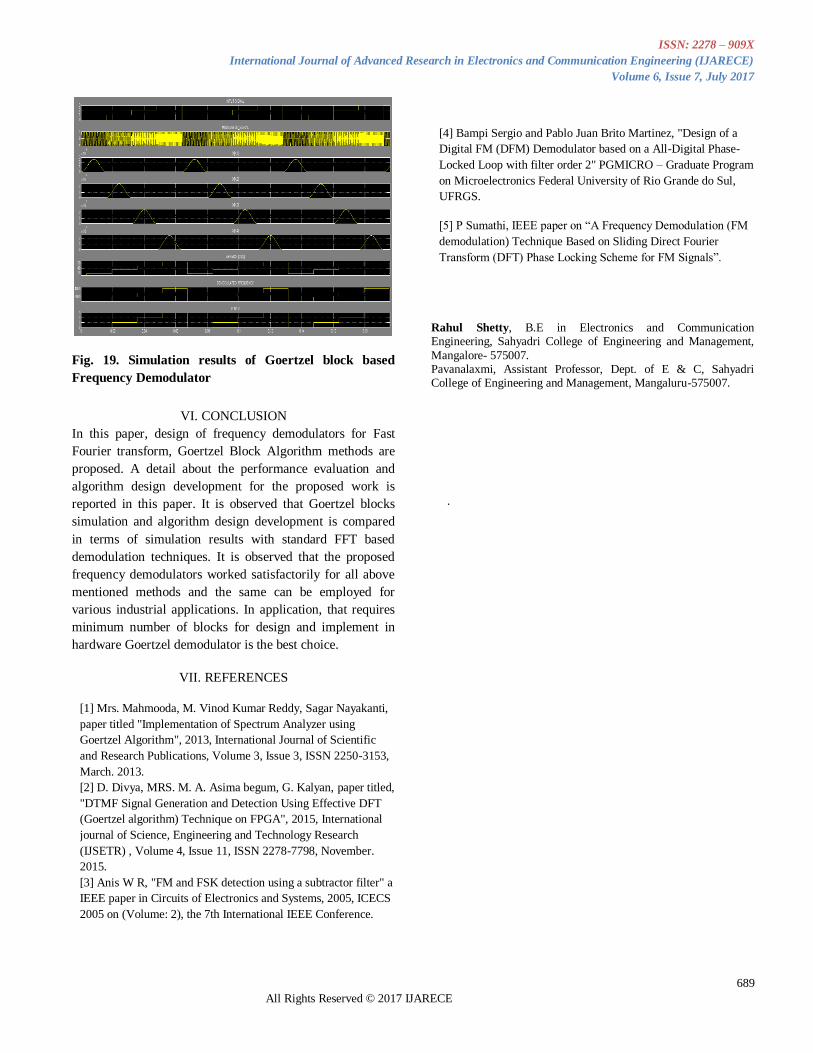
Similarly the simulation waveform results of the Goertzel
based frequency demodulator is shown in Fig. 19. In Fig.
19, the first waveform is input signal fed to the Frequency
modulator from external counter signal to the modulator
block as input, second waveform is the frequency output,
which is based on the counter bit signal the waveform is
generated inside on the modulator block. For example, if
you provide 2 bit counter as an input to the modulator, four
steps from 0 to 3 is generated in the counter and that is
given as a input to the modulator block. For every step,
there is a generation of frequency with the frequency
deviation. Here, frequency deviation is considered as 1
KHz. so, for the first step it will generate 1 KHz which is
added to previous generated sine wave frequencies. The
next consecutive four waveforms represent the Goertzel
block output X[k] computed from 2nd order filter designed
based on the parameter set into the filter block. The value of
X[k] which is high only for specified detected Goertzel
block and other Goertzel block magnitude value is very less
compared to detected frequency energy. The next
waveforms Goertzel frequency index 'k' value and next
waveform is frequency detection, it is done based frequency
index value and logic is implemented explained in previous
chapter. Based on the frequency detection, it is converted
into the corresponding voltage value.
ISSN: 2278 – 909X
International Journal of Advanced Research in Electronics and Communication Engineering (IJARECE)
Volume 6, Issue 7, July 2017
689
All Rights Reserved © 2017 IJARECE
Fig. 19. Simulation results of Goertzel block based
Frequency Demodulator
VI. CONCLUSION
In this paper, design of frequency demodulators for Fast
Fourier transform, Goertzel Block Algorithm methods are
proposed. A detail about the performance evaluation and
algorithm design development for the proposed work is
reported in this paper. It is observed that Goertzel blocks
simulation and algorithm design development is compared
in terms of simulation results with standard FFT based
demodulation techniques. It is observed that the proposed
frequency demodulators worked satisfactorily for all above
mentioned methods and the same can be employed for
various industrial applications. In application, that requires
minimum number of blocks for design and implement in
hardware Goertzel demodulator is the best choice.
VII. REFERENCES
[1] Mrs. Mahmooda, M. Vinod Kumar Reddy, Sagar Nayakanti,
paper titled "Implementation of Spectrum Analyzer using
Goertzel Algorithm", 2013, International Journal of Scientific
and Research Publications, Volume 3, Issue 3, ISSN 2250-3153,
March. 2013.
[2] D. Divya, MRS. M. A. Asima begum, G. Kalyan, paper titled,
"DTMF Signal Generation and Detection Using Effective DFT
(Goertzel algorithm) Technique on FPGA", 2015, International
journal of Science, Engineering and Technology Research
(IJSETR) , Volume 4, Issue 11, ISSN 2278-7798, November.
2015.
[3] Anis W R, "FM and FSK detection using a subtractor filter" a
IEEE paper in Circuits of Electronics and Systems, 2005, ICECS
2005 on (Volume: 2), the 7th International IEEE Conference.
[4] Bampi Sergio and Pablo Juan Brito Martinez, "Design of a
Digital FM (DFM) Demodulator based on a All-Digital Phase-
Locked Loop with filter order 2" PGMICRO – Graduate Program
on Microelectronics Federal University of Rio Grande do Sul,
UFRGS.
[5] P Sumathi, IEEE paper on “A Frequency Demodulation (FM
demodulation) Technique Based on Sliding Direct Fourier
Transform (DFT) Phase Locking Scheme for FM Signals”.
Rahul Shetty, B.E in Electronics and Communication Engineering, Sahyadri College of Engineering and Management,
Mangalore- 575007. Pavanalaxmi, Assistant Professor, Dept. of E & C, Sahyadri College of Engineering and Management, Mangaluru-575007.
.