design of a quadruped robot for human–elephant conflict mitigation
TRANSCRIPT
ORIGINAL ARTICLE
Design of a quadruped robot for human–elephant conflictmitigation
S. J. Sugumar • R. Jayaparvathy
Received: 23 March 2013 / Accepted: 30 August 2013 / Published online: 7 November 2013
� ISAROB 2013
Abstract
Introduction Human–elephant conflict is a major problem
leading to crop damage, human death by elephants and
elephants being killed by people. The surveillance and
tracking of elephant herds are difficult due to their size and
nature of movement.
Materials In this article, we propose a four-wheeled
quadruped robot to mitigate human–elephant conflict. The
robot can detect movement of wild pachyderms in certain
pockets along the forest borders through which the ele-
phants enter into the human living areas from the forest.
The robot is so designed that it can navigate with wheels on
flat terrains and with legs on unfriendly rugged terrains
with the help of mounted cameras.
Methods The images of the wild elephant are captured
and transmitted to the base stations and an SMS is sent to
the forest officials indicating an elephant is found. We
obtain a suitable kinematic model for both legs and wheels
with control algorithm for the quadruped robot to move
along a predetermined path.
Conclusion The quadruped robot proposed is a solution
to detect elephant movement without affecting the eco-
logical conditions to overcome human–elephant conflict.
The unpredictability of time and location of elephant
arrival into the villages are considered the major issues that
are resolved in this work. The results of our work con-
tribute to elephant conservation issues and are suitable for
the detection of elephants in forest border areas.
Keywords Kinematic � Degree of freedom � Legged
robot � Quadruped � Leg-wheeled robot
1 Introduction
India is home to 60 % of the Asian elephant population.
According to Project Elephant, a government initiative for
elephant conservation, there were 28,000 elephants in the
country in 2011. Coimbatore forest is a habitat for elephants
in India. Elephant intrusion along the forest border areas is
the common problem in this division. Elephants intrude into
farm fields and villages and cause damage. Man–animal
conflict has been on the rise in the forest border areas with
herds of wild pachyderms straying into human habitation
[1]. Till recently, the Coimbatore forest department tried
using powerful searchlights, crackers, and drums to push the
wild elephant herds back into the jungle. The Kumki (Res-
cue) elephants were used more in hill areas to chase the herds
of wild elephants into the forests. Surveillance and tracking
of these herds are difficult due to their size and nature of
movement. The loss due to destruction in the farms is more.
The elephants are also subject to attack by humans resulting
in danger to the life of elephants [2]. Many approaches have
been used to detect the intrusion of the elephants. One such
approach is to use seismic geophones as underground sen-
sors to sense and produce an output voltage based on the
vibration produced when the elephants walk in the detection
range of the seismic geophones.
In this paper, we propose an enhancement to the
aforesaid elephant intrusion detection system. The wheeled
quadruped robot can be used for such intrusion detection
system. Despite its success on wheeled locomotion for
predetermined and plane surfaces, it is not suitable for
unknown and rough terrains. The tracked locomotion is
S. J. Sugumar (&)
Coimbatore Institute of Technology, Coimbatore, India
e-mail: [email protected]
R. Jayaparvathy
SSN College of Engineering, Chennai, India
e-mail: [email protected]
123
Artif Life Robotics (2013) 18:204–211
DOI 10.1007/s10015-013-0120-2
developed to cope with this problem. However, tracked
locomotion is also not without problems, since it destroys
the terrain on which the vehicle is moving. As an alter-
native to both wheeled and tracked movements, legged
locomotion is developed by imitating the legged animals in
nature [3]. Wheeled and legged mobile robot path planning
has received great attention and several models and algo-
rithms have been developed for the detection and overcoming
of obstacles and in the development of skills that allow robots
to walk on irregular surfaces with obstacles [4].
In [5] Belter et al. discussed a multi-layered drive control
for walking robot. This was implemented by using six-leg-
ged robot with 18 degrees of freedom (DOF). Each joint used
one DC servomotor, and synchronization was done among
the legs using master slave concept. The authors also
addressed sensing system issues for walking robot using
closed control loops through these sensors. In [6] Amaral
et al. designed a robot that walked on straight, curved paths,
detecting and overcoming known obstacles. The robot used
only feet sensor information and managed standalone
movement sequences to position the robot and to overcome
obstacles. In [7] Szrek and Wojtowicz constructed the Leg-
Van wheel-legged robot with an autonomous leveling and
obstacle detection system. They presented the robot’s kine-
matic wheel suspension system, general operation strategy,
and control system. In [8] Raibert et al. developed a new
breed of rough-terrain robots called BigDog that captured the
mobility, autonomy, and speed of living creatures. Such
robots could travel in outdoor rough terrains which are dif-
ficult to travel for conventional robot vehicle platforms.
In this work, a four-legged and wheeled robot, namely the
wheeled quadruped robot is developed specially to move in
any terrain i.e., both walk using legs and move on wheels.
The elephants in the forest always move along specific cor-
ridors in search of food and water. These corridors are
commonly called as elephant corridors. They enter the farm
lands by passing through certain pockets along the forest
borders. We propose a technique to use robots in detecting
elephants in forest border areas only, not inside the forest.
The robot we design can be laid in certain elephant pockets
through which the elephants normally come out of the forest
and enter human habitat region. This design is made in such a
way the quadruped robot is made to move in predetermined
path to capture the elephant image in and around these
pockets. This work is done as a solution to human–elephant
conflict, which is predominant in the Coimbatore forest
division in Tamil Nadu, India.
2 Quadruped architecture
In our previous work ‘‘An Early Warning System for Ele-
phant Intrusion Detection along the Forest Border Areas’’
[9], sensors namely seismic geophones are buried under the
ground. If the elephant walks in the sensing range of the
geophones, the vibrations are converted to an electrical
signal and the signal is fed to a controller which sends an
SMS to the forest officials for necessary action. In such
intrusion detection systems there is a possibility of insuffi-
cient vibrations sensed by the geophones as a consequence
of weather conditions like rain. Due to this it may miss the
event i.e., elephant movement detection in the forest border
areas. A wheeled quadruped robot (WQR) is proposed in
this work which can navigate with wheels on flat terrains
and with legs on rugged terrains. The robot is designed in
such a way that it can move on unfriendly terrains with the
help of cameras mounted on the mobile robots [10]. The
elephants come out of the forest through certain pockets to
enter into villages for getting food and water during dry
seasons. The proposed robots can be made to move in the
elephant pockets for detecting the entry of elephants into the
human living areas. The image captured by the robot is
processed and compared with the stored image of elephants.
When the image matches, SMS is sent to the forest officials
through the GSM transceiver connected with the controller.
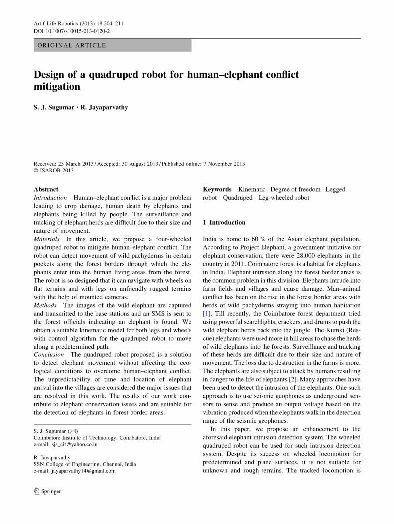
The image capture unit is shown in Fig. 1.
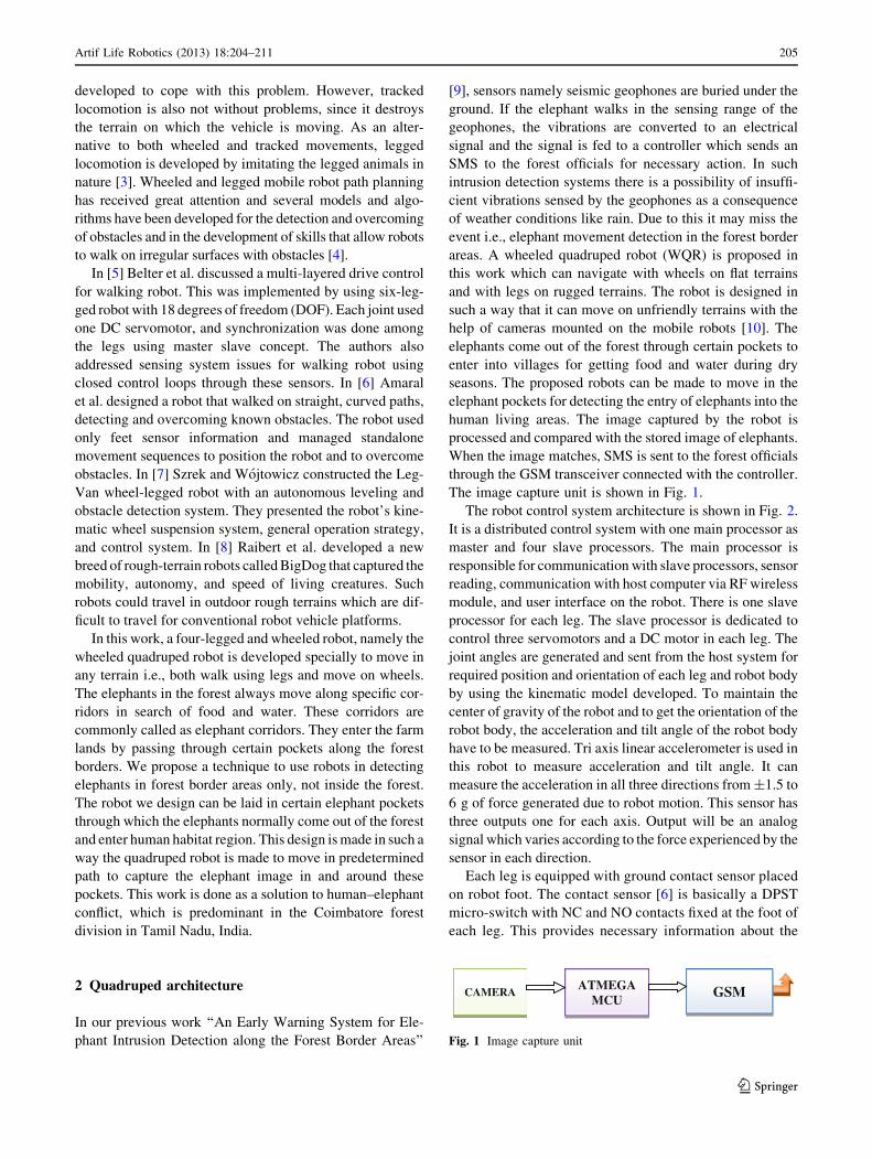
The robot control system architecture is shown in Fig. 2.
It is a distributed control system with one main processor as
master and four slave processors. The main processor is
responsible for communication with slave processors, sensor
reading, communication with host computer via RF wireless
module, and user interface on the robot. There is one slave
processor for each leg. The slave processor is dedicated to
control three servomotors and a DC motor in each leg. The
joint angles are generated and sent from the host system for
required position and orientation of each leg and robot body
by using the kinematic model developed. To maintain the
center of gravity of the robot and to get the orientation of the
robot body, the acceleration and tilt angle of the robot body
have to be measured. Tri axis linear accelerometer is used in
this robot to measure acceleration and tilt angle. It can
measure the acceleration in all three directions from ±1.5 to
6 g of force generated due to robot motion. This sensor has
three outputs one for each axis. Output will be an analog
signal which varies according to the force experienced by the
sensor in each direction.
Each leg is equipped with ground contact sensor placed
on robot foot. The contact sensor [6] is basically a DPST
micro-switch with NC and NO contacts fixed at the foot of
each leg. This provides necessary information about the
CAMERAATMEGA
MCUGSM
Fig. 1 Image capture unit
Artif Life Robotics (2013) 18:204–211 205
123
contact between the robot foot and surface of the terrain for
the control system of the robot. An IR optical sensor is used
as the wheel position encoder. To model the position and
orientation of the robot in global frame when it navigates,
angular position and angular velocity for each wheel are
calculated. This encoder gives the wheel angular position
uj and angular velocity xj for the jth wheel. The analog
servomotors are used as the actuators in each leg joint. The
analog servomotors have an integrated potentiometer to
enable closing of the feedback-loop in the position control
mode. Each servomotor has to be manually calibrated to
avoid the errors in position control.
The mechanical frame of the robot is designed with alu-
minum metal sheet to minimize the weight. DC servomotors
with integrated nylon gear have been chosen to drive each
robot leg joint. This servomotor has a stall torque of
0.314 Nm. The knee of each leg was designed with option to
connect a DC motor with the wheel. These four wheels can
reach the terrain surface when all the four legs are folded
under the robot body as shown in Fig. 3. This option enables
it to navigate through wheels on flat terrains.
The DC motor has an integrated reduction gear box and
it has a torque of 0.49 Nm. Each part of the robot body is
designed separately by part designing tools in Solid Works
[11] and the parts are assembled to form the body structure
using the assembling tool.
3 Kinematic of the robot
Kinematic is the science of geometry in motion [12]. It is
restricted to a pure geometrical description of motion by
means of position, orientation, and their time derivatives.
The links and joints in a robotic system are modeled as
rigid bodies, and the properties of rigid body displacement
takes a central place in robotics. In this work, a kinematic
controlled four-legged and wheeled robot named the
wheeled quadruped robot is developed. We obtain a suit-
able kinematic model and control algorithm that can help
the quadruped robot to move along a predetermined path to
detect elephant movement along forest border areas.
3.1 Kinematic modeling of robot legs
A systematic method for kinematic modeling of four-leg-
ged robots for walking on rough terrain is developed in this
work. A kinematic model for characterizing the robot joints
and linkage parameters that capture the motion of quad-
ruped robot is developed. The equations of motions are set
up using this table for different frames starting from the
robot reference frame, going through individual legs and
finally reaching feet-terrain contact frames. The composite
equation of motion is formed from those of individual legs.
The formulation allows determining actuations to various
joints for achieving a desired robot motion, while opti-
mizing a performance index such as a stability measure.
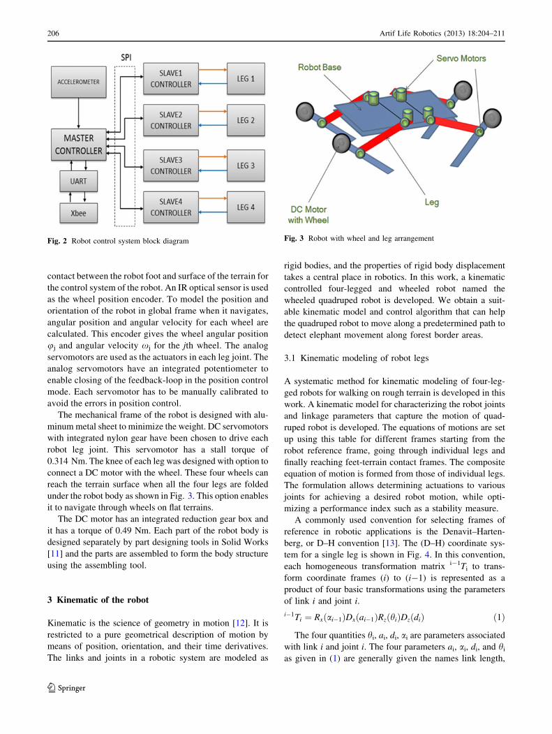
A commonly used convention for selecting frames of
reference in robotic applications is the Denavit–Harten-
berg, or D–H convention [13]. The (D–H) coordinate sys-
tem for a single leg is shown in Fig. 4. In this convention,
each homogeneous transformation matrix i-1Ti to trans-
form coordinate frames (i) to (i-1) is represented as a
product of four basic transformations using the parameters
of link i and joint i.
i�1Ti ¼ Rx ai�1ð ÞDx ai�1ð ÞRz hið ÞDzðdiÞ ð1Þ
The four quantities hi, ai, di, ai are parameters associated
with link i and joint i. The four parameters ai, ai, di, and hi
as given in (1) are generally given the names link length,
Fig. 2 Robot control system block diagram Fig. 3 Robot with wheel and leg arrangement
206 Artif Life Robotics (2013) 18:204–211
123
link twist, joint distance, and joint angle, respectively [14].
The matrix Ti is a function of a single variable, it turns out
that two of the above four quantities are constant for a
given link, while the fourth parameter, hi for a revolute
joint and di for a prismatic joint, is the joint variable.
Considering aj,i-1: Link length, aj,i-1: Link twist, dj,i:
Joint distance, hj,i: Joint angle transformation between i–ith
frame and ith is given by
j;i�1Tj;i ¼
chj;i �shj;i 0 aj;i�1
shj:icaj;i�1 chj;icaj;i�1 �saj;i�1 �saj;i�1dj;i
shj;isaj;i�1 chj;isaj;i�1 caj;i�1 caj;i�1dj;i
0 0 0 1
2664
3775
ð2Þ
where chj,i stands for cos(hj,i), shj,i stands for sin(hj,i), c
aj,i-1 stands for cos(aj,i-1), s aj,i-1 stands for sin(aj,i-1) and
L stands for Link state.
j;0Tj;1 ¼
chj;1 �shj;1 0 Lj;0
shj;i chj;1 0 0
0 0 1 0
0 0 0 1
2664
3775 ð3Þ
j;1Tj;2 ¼
chj;2 �shj;2 0 Lj;1
0 0 �1 0
shj;2 chj;2 0 0
0 0 0 1
2664
3775 ð4Þ
j;2Tj;3 ¼
chj;3 �shj;3 0 Lj;2
shj;3 chj;3 0 0
0 0 1 0
0 0 0 1
2664
3775 ð5Þ
j;3Tj;4 ¼
1 0 0 Lj;3
0 1 0 0
0 0 1 0
0 0 0 1
2664
3775 ð6Þ
The total transformation between the body of the robot
and foot of the jth robot leg is
j;0Tj;4 ¼ j;0Tj;1 � j;1Tj;2 � j;2Tj;3 � j;3Tj;4 ð7Þ
from Eqs. (2) to (6)
j;0Tj;4 ¼
t11 t12 t13 t14
t21 t22 t23 t24
t31 t32 t33 t34
0 0 0 1
2664
3775 ð8Þ
where
t11 ¼ chj;1chj;2chj;3 � chj;1shj;2shj;3
t12 ¼ �chj;1chj;2shj;3 � chj;1shj;2chj;3; t13
t14 ¼ chj;1chj;2ðLj;3chj;3 þ Lj;2Þ � chj;1shj;2shj;3Lj;3
þ Lj;1chj;1 þ Lj;0
t21 ¼ shj;1chj;2chj;3 � shj;1shj;2shj;3
t22 ¼ �shj;1chj;2shj;3 � shj;1shj;2chj;3; t23
t24 ¼ shj;1chj;2ðLj;3chj;3 þ Lj;2Þ � shj;1shj;2shj;3Lj;3 þ Lj;1shj;1
t31 ¼ shj;2chj;3 þ chj;2shj;3; t32 ¼ �shj;2shj;3 þ chj;2chj;3
t33 ¼ 0; t34 ¼ shj;2ðLj;3chj;3 þ Lj;2Þ þ chj;2shj;3Lj;3
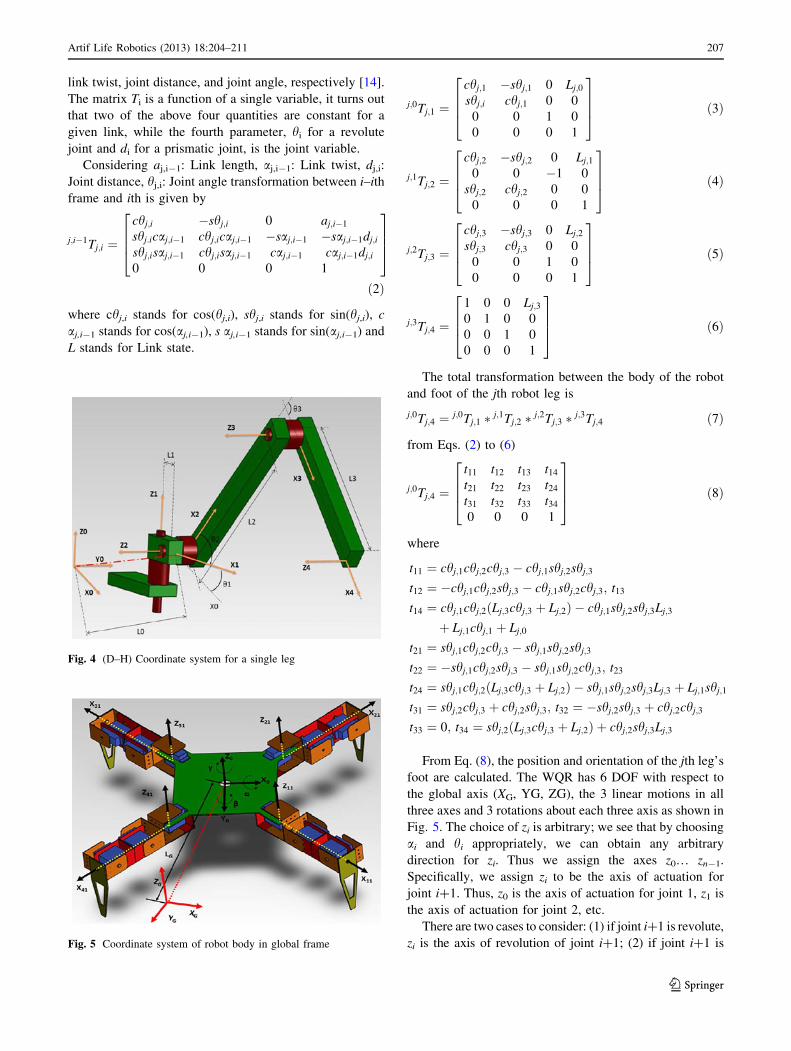
From Eq. (8), the position and orientation of the jth leg’s
foot are calculated. The WQR has 6 DOF with respect to
the global axis (XG, YG, ZG), the 3 linear motions in all
three axes and 3 rotations about each three axis as shown in
Fig. 5. The choice of zi is arbitrary; we see that by choosing
ai and hi appropriately, we can obtain any arbitrary
direction for zi. Thus we assign the axes z0… zn-1.
Specifically, we assign zi to be the axis of actuation for
joint i?1. Thus, z0 is the axis of actuation for joint 1, z1 is
the axis of actuation for joint 2, etc.
There are two cases to consider: (1) if joint i?1 is revolute,
zi is the axis of revolution of joint i?1; (2) if joint i?1 isFig. 5 Coordinate system of robot body in global frame
Fig. 4 (D–H) Coordinate system for a single leg
Artif Life Robotics (2013) 18:204–211 207
123
prismatic, zi is the axis of translation of joint i?1. The joint i is
fixed with respect to frame i, and when joint i is actuated, link
i and its attached frame, oi xi yi zi, experience a resulting
motion [15]. Once the z-axes for the links have been estab-
lished, the base frame is constructed. The choice of a base
frame is nearly arbitrary. We may choose the origin O0 of the
base frame to be any point on z0. We then choose x0, y0 in any
convenient manner so long as the resulting frame is right-
handed. This sets up frame 0. Once frame 0 has been estab-
lished, we begin an iterative process in which we define frame
i using frame i-1, beginning with frame 1. The D–H
parameter of a robot leg is given in Table 1.
The vector Q contains the orientation and position
vectors of the WQR.
Q ¼
x
y
z
abc
26666664
37777775
ð9Þ
The absolute linear position of the WQR is defined in
the global frame XG, YG, ZG-axes as n.
n ¼x
y
z
2435 ð10Þ
The absolute angular position of the WQR is defined in
the global frame XG, YG, ZG-axes as g.
g ¼abc
2435 ð11Þ
where, a is the roll angle that determines the rotation about
X0 axis, b is the pitch angle that determines the rotation
about Y0 axis, c is the yaw angle, that determines the
rotation about Z0 axis. The rotation matrix from the body
frame to the global frame is
RG ¼cccb casbsa� scca ccsbcaþ scsasccb scsbsaþ ccca scsbca� ccsa�sb cbsa cbca
24
35 ð12Þ
where, cx stands for cos(x) and sx stands for sin(x).
Let ni-1 = [xi-1 yi-1 zi-1]T and ni = [xi yi zi]T denote the
position of the current and next frames of the robot,
respectively [16]. Similarly, let gi-1 = [ai-1 bi-1 ci-1]T and
gi = [ai bi ci]T be the orientation of the previous and current
frames of the robot, respectively, where ai bi ci are the
rotation around x, y and z axis, or roll, pitch, and yaw,
respectively derived from (10) and (11). Using the D–H
notation, the transformation from the frame Fi-1 to the frame
of the robot Fi is obtained by rotation hi about z-axis, trans-
lation di along z-axis and rotation2i about x-axis. The results
of the transformation are provided in the result section.
3.2 Kinematic of robot wheel
Let xi and vi, s = 1… 4 denote the wheel angular and
center linear velocities, respectively. From the aforemen-
tioned assumption, we have the angular velocity as
xL: = x1 = x2, xR: = x3 = x4 and the linear velocities
vL : = v1 = v2, vR : = v3 = v4. The linear velocity corre-
sponds to the left wheel and right wheel velocities [17].
The front left and front right wheels provide the direction
of orientation of the quad robot as shown in Fig. 6. The
back right and left wheels provide the speed the robot. We
consider the quadruped robot moving on two dimensional
planes with inertial coordinate frame (Xg, Yg). To describe
motion of the robot, we define a local frame attached to it
with origin in its robot mass center (RMC). Assume that q
, [X Y h]T [R3 denotes generalized coordinates, where X,
Y determine RMC position and h is an orientation of the
local frame with respect to the inertial frame, respectively.
The change of angle from the inertial frame is the heading
angle. Let v , [vx vy]T [ R
3 be a velocity vector of RMC
expressed in the local frame with vx and vy determining lon-
gitudinal and lateral velocity of the quad robot. The longitu-
dinal velocity determines the direction of rotation and the
lateral velocity determines speed of the robot, which we
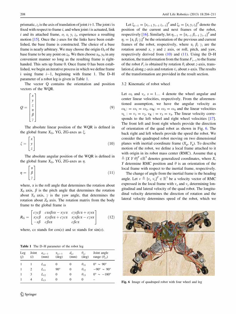
Fig. 6 Image of quadruped robot with four wheel and leg
Table 1 The D–H parameter of the robot leg
Leg
(j)
Joint
(i)
aj,i-1
(mm)
aj,i-1
(deg)
dj,i
(mm)
hj,i
(deg)
Joint angle
range (hj,i)
1 1 L10 0 0 h11 0� * 90�1 2 L11 90� 0 h12 -90� * 90�1 3 L12 0 0 h13 0� * -180�1 4 L13 0 0 0 –
208 Artif Life Robotics (2013) 18:204–211
123

consider to be constant. The kinematic equation of motion
using rotation matrix [18] is given as follows
_q ¼_X_Y_h
24
35 �
cosh �sinh 0
sinh cosh 0
0 0 1
24
35 �
vx
vy
x
24
35 ð13Þ
where _q [R3 is the generalized velocity vector and x denotes
angular velocity of the vehicle. xL and xR which denote
angular velocities of left and right wheels, respectively, can be
regarded as control inputs at kinematic level and can be used to
control longitudinal and lateral velocity. The longitudinal
velocity is given by
vx ¼ rxR þ xL
2; ð14Þ
Lateral velocity vy which determines velocity of lateral
slip of the vehicle can be obtained as follows
vy ¼ xCORx ð15Þ
where xCOR is a coordinate of instantaneous center of
rotation (COR) expressed along x-axis. We assume that
xCOR = const. It can be written as
vy ¼ x0x ð16Þ
where x0 is the geometrical parameter and the angular
velocity is obtained from the following equation
x ¼ rxR � xL
2cð17Þ
where r is so called effective radius of wheels and 2c is a
spacing between left and right wheel. The orientations to
move to the destination are provided to the controller. The
controller calculates the new heading angle [19] by which
the quad robot should rotate for movement. The angular
difference between the robot heading and a fixed point on
the surface is provided by the heading angle and is
calculated as follows
hHA ¼ tan�1 ydestn � ysource
xdestn � xsource
� �� �ð18Þ
The controller adjusts xL and xR to maintain a fixed
distance from the x-axis, and to maintain hHA = 0 for a
straight travel from source to destination. The results are
plotted in the next section.
4 Simulation and testing
The Kinematic model has been developed in this work for
the robot legged motion and is simulated using MATLAB
[20]. The position and orientation parameters of the robot
are generated and the parameters are plotted in 3D graph to
visualize the posture of the robot.
The computed joint parameters are sent to the robot via
RF module. The robot hardware setup takes the posture that
is generated by the kinematic model from the received joint
parameter data. Figure 7 shows the 3D graph of the posture
of robot. The same parameter was used for the posture of
leg in hardware.
Once the joint angle data are received from host system,
then the robot’s master controller sends joint angle data to the
corresponding slaves via SPI. The received tilt angle infor-
mation from accelerometer is used to find the orientation of
robot body. The calculated orientation is visualized in 3D plot.
In Fig. 8, the green square represents the robot body and red
square represents the plane perpendicular to the direction of
gravity. The orientation of the body when the roll angle
a = 35� and the pitch angle is b = 25�, and for different roll
and pitch angles of the robot body is generated and verified
with the corresponding robot movement. To maintain the
center of gravity of the robot, all three angular displacements
should be nearer to 0� as possible. If the three angular dis-
placements are not nearer to zero then the joint angles are
recalculated by the kinematic model for the same foot position
to maintain the center of gravity i.e., making the roll, pitch, and
yaw nearer to zero without change in foot position.
The joint angle information will be generated using the
kinematic model of the WQR. The joint angle information
is sent to the robot to control the servomotor.
This test was carried out to verify whether the generated
pulse width modulation (PWM) signal to control the servo-
motor shaft angle position is appropriate to the received joint
angle information. The PWM signal is viewed for different
joint angles, and the PWM signal generated for joints J22, J23,
J41, J31 is shown in Fig. 9. The calibrated PWM ON time
value for joint servomotors is provided in Table 2.
Fig. 7 The 3D graph of the leg posture
Artif Life Robotics (2013) 18:204–211 209
123

The simulation is performed in Matlab environment to
verify behavior of the quadruped robot wheel. Permissible
torque signal is max = 0.25 Nm and angular velocities of
wheels = 56[rad/s]. From Fig. 10, the response of velocity
we can estimate the time constant of the robot system and
adjust the control gains accordingly. The velocity response
generated by the robot wheel which after a 150 ms the robot
control system reaches the desired linear velocity in which the
speed of the robot is constant during the motion of path from
the source point to destination point.
Figure 11 shows the robot heading angle of the quad robot.
The robot starts with a zero heading angle and takes a small
deviation and adjusts the position to the center of path and
reaches the zero heading angles again after 180 ms. Once the
zero heading angles are reached the robot moves in a straight
direction and follows the path.
4.1 Testing of the wheeled quadruped robot
The Robot Prototype directly linked with Host computer
via serial port to test the controlling options through
MATLAB GUI [21]. The joint angle information is sent to
the robot master control unit. The received joint angle
information from host then processed by the master control
unit and sent to slave control units. The robot does the
motion generated according to the kinematic model. Fig-
ure 12 shows that the robot makes the same posture plotted
in GUI. This test proves that the communication between
host and robot master control unit and communication
between master and slaves are working properly. Any
sequence of motion can be generated by host system and
sent to the robot for navigation on rough surface.
Fig. 8 Orientation of robot body when its roll is 35�
Fig. 9 PWM for J22, J23, J41, J31
Fig. 10 Linear velocity generated by the WQR
Table 2 Calibrated PWM on time value for joint servomotors
0� 45� 90� 135� 180� Angle
Motor
A 2450 2050 1625 1210 800 Servomotor PWM signal
on time values (in ls)
pulse period 20 msB 650 1040 1425 1810 2200
C 575 930 1300 1700 2100
D 550 925 1300 1700 2100
E 675 975 1375 1750 2150
F 565 910 1325 1725 2075
G 650 1070 1500 1970 2450
H 550 1000 1450 1900 2350
I 525 945 1365 1830 2300
J 500 925 1350 1800 2250
K 540 970 1400 1865 2325
L 525 930 1370 1820 2300
M 550 980 1425 1900 2400
210 Artif Life Robotics (2013) 18:204–211
123

5 Conclusion
The wheeled quadruped robot proposed in this work is used
to monitor and detect the elephant in the forest border areas
as a solution to human–elephant conflict. The kinematic
model for the legged motion has been developed in such a
way to enable movement in any terrain. The posture of WQR
body has been plotted using 3D plot in graphical user inter-
face environment and the same configuration of robot pos-
ture is verified using the designed WQR hardware. The
orientation of the robot body with respect to the plane per-
pendicular to direction of gravitational force is monitored in
3D plot. The walking motion of robot has been tested in
different terrains. The auto navigation of robot for walking in
all terrains can be done using this kinematic model. Kine-
matic model of wheeled locomotion is developed and tested.
The proposed method can be used as an effective scheme to
detect elephants in the forest border areas.
References
1. Kumara HN, Rathnakumar S, Ananda Kumar M, Singh M (2012)
Estimating Asian elephant, Elephas maximus, density through
distance sampling in the tropical forests of Biligiri Rangaswamy
Temple tiger reserve, India. Trop Conserv Sci 5.2:163–172
2. Lenin J, Sukumar R (2008) Action plan for the mitigation of
elephant–human conflict in India. Transformation 10:35
3. Bottcher S (2006) Principles of robot locomotion. In: Proceedings
of human robot interaction seminar
4. Bruzzone L, Quaglia G (2012) Robots in unstructured environ-
ments. Mech Sci 3:49–62
5. Belter D, Walas K, Kasinski A (2008) Distributed control system
of DC servomotors for six legged walking robot. In: 13th inter-
national power electronics and motion control conference, IEEE,
pp 1044–1049
6. Amaral PFS, Pinto BGM (2010) A four legged walking robot
with obstacle overcoming capabilities. In: 3rd conference on
human system interactions (HSI), IEEE, pp 374–379
7. Szrek J, Wojtowicz P (2010) Idea of wheel-legged robot and its
control system design. Bull Pol Ac Sci Tech Sci 58(1):43–50
8. Raibert M, Blankespoor K, Nelson G, Playter R (2008) Bigdog,
the rough-terrain quadruped robot. In: Proceedings of the 17th
World Congress, pp 10823–10825
9. Sugumar SJ, Jayaparvathy R (2013) An early warning system for
elephant intrusion along the forest border areas. Curr Sci
104(11):1515–1526
10. Chen J, Dixon WE, Dawson M, McIntyre M (2006) Homogra-
phy-based visual servo tracking control of a wheeled mobile
robot. IEEE Trans Robot 22(2):406–415
11. Solid Works (2011) User guide
12. Dahari M, Tan JD (2011) Forward and inverse kinematics model
for robotic welding process using KR-16KS KUKA robot. In:
Modeling, simulation and applied optimization (ICMSAO), 4th
international conference on IEEE, pp 1–6
13. Denavit J (1955) A kinematic notation for lower-pair mechanisms
based on matrices. Transaction of the ASME. J Appl Mech
22:215–221
14. Kucuk S, Bingul Z (2006) Robot kinematics: forward and inverse
kinematics. Industrial robotics theory modeling & control. ARS/
pIV, Germany, pp 117–148
15. Calderon CA, Alfaro EMRP, Gan JQ, Hu H (2004) Trajectory
generation and tracking of a 5-DOF robotic arm. Control
16. Wang, H, Qi Z, Xu G, Xi F, Hu G, Huang Z (2010) Kinematics
analysis and motion simulation of a quadruped walking robot
with parallel leg mechanism. Open Mech Engg J 4(1):77–85
17. Kozłowski K, Pazderski D (2004) Modeling and control of a
4-wheel skid-steering mobile robot. Int J Appl Math Comp Sci
14:477–496
18. Kumar U, Sukavanam N (2007) Dynamic modeling and tracking
control of a four wheeled nonholonomic mobile robot. In: 13th
national conference on mechanics and machines (NaCoMM07),
December 12–13
19. Lee D, Martinez-Palafox O, Spong MW (2006) Bilateral tele-
operation of a wheeled mobile robot over delayed communication
network. In: Robotics and Automation, ICRA, Proceedings of the
2006 IEEE international conference on robotics and automation
Orlando, pp 3298–3303
20. Rong X, Song R, Li B (2012) Simulation for sagittal plane
motions of a quadruped robot using MATLAB and Simulink.
J Info Comput Sci 9(8):2165–2173
21. Alshamasin MS, Ionescu F, Al-Kasasbeh RT (2012) Modeling
and simulation of a SCARA robot using solid dynamics and
verification by MATLAB/Simulink. Int J Model Identif Control
15(1):28–38
Fig. 11 Heading angle of the WQR
Fig. 12 Testing of robot controlling through GUI
Artif Life Robotics (2013) 18:204–211 211
123