design f a hot oil heat exchanger system · pdf filereasonable pressure drop in the heat...
TRANSCRIPT
International Journal of Applied Engineering Research ISSN 0973-4562 Volume 11, Number 20 (2016) pp. 10102-10124
© Research India Publications. http://www.ripublication.com
10102
Design of A Hot Oil Heat Exchanger System
Karthik Silaipillayarputhur Ph.D. & Tawfiq Al Mughanam Ph.D.
Department of Mechanical Engineering King Faisal University, Kingdom of Saudi Arabia, 31982
Abdulmajeed Abdullah H Al Abdul Qader,
Moath Mohammed E Al Saikhan & Abdulrahim Abdulrazaq Al Abdulwahed
Department of Mechanical Engineering King Faisal University, Kingdom of Saudi Arabia, 31982
Abstract
This work presents the design of a hot oil heat exchanger
system wherein the heat exchanger and its associated pumping
system is developed by employing engineering standards. An
iterative mathematical approach is employed in the design of a
hot oil concentric tube heat exchanger (HX). The actual
conditions of the hot oil system from a chemical plant in
Chattanooga, TN is considered in this analysis. A
mathematical model is developed such that the required heat
exchanger’s dimensions and flow requirements are deduced to
necessitate a specified heat transfer. Thereafter, the
development of a pumping system for the hot oil heat
exchanger is examined.
Keywords: Heat Exchanger Modeling, Hot Oil System,
Concentric Tube Heat Exchanger
INTRODUCTION
Heat exchanger is an equipment used to transfer heat from a
higher temperature fluid to a lower temperature fluid. Therein,
a solid wall separates the two fluids. Heat exchangers can be
classified based on flow and construction. Based on
construction, heat exchangers can be classified as concentric
tube heat exchangers, shell and tube heat exchangers and
finned/unfinned heat exchangers. Likewise, based on flow,
they can be classified as parallel flow, counter flow or cross
flow. The choice of construction and flow circuiting are
dictated by the application and by the existing piping
connections available in the process plant.
In this paper, a hot oil concentric tube heat exchanger is
developed for a hot oil system in a chemical plant in
Chattanooga, TN. The hot oil is used for a certain process
heating application in the chemical plant. The hot oil flows
through the inner pipe, i.e., on the tube-side, and steam flows
through the annular space. It is assumed that abundant steam
flow rate is available to provide the required heating of the oil
in the concentric tube heat exchanger.
There are numerous references available in the literature
pertaining to heat exchanger performance modeling, and only
the most pertinent are discussed. Silaipillayarputhur and Idem
[1, 2] developed matrix approach for design and performance
evaluation of crossflow heat exchangers. Therein, the thermal
performance of the heat exchanger was evaluated at every
pass of the heat exchanger. Matrix approach helps the heat
exchanger designers to develop the optimum and a cost
efficient heat exchanger. Domingos [3] presented a general
method of calculating the total effectiveness and intermediate
temperatures of assemblies of heat exchangers. The
assemblies may consist of associations of any types of heat
exchanger. The method utilizes a transformation that relates
the inlet and outlet temperatures of the fluid streams and this
permits the derivation of closed form expressions. Pignotti
and Shah [4] and Shah and Pignotti [5] discussed the tools
developed previously (such as Domingos’ method, the
Pignotti chain rule, etc.) to determine the relationship for
highly complex heat exchanger flow arrangements. Navarro
and Gomez [6] developed a mathematical model for cross
flow heat exchangers for determining the Effectiveness-NTU
(number of transfer units) relations. The model developed
represents a useful research tool for theoretical and
experimental studies on heat exchanger performance. Gomez
et.al [7] studied the thermal performance of multi pass parallel
and counter cross flow heat exchangers by applying a new
numerical procedure. The thermal effectiveness of the heat
exchanger at various passes with respect to capacity rate ratio
and NTU are presented in the form of tables.
Silaipillayarputhur et.al [8] developed a pumping system for a
heat transfer fluid. Therein, the details for choosing an
appropriate pump, head loss calculations, net positive suction
head (NPSH) calculations are detailed and such concepts are
applied in this work while designing pumping system for the
heat exchanger.
LIST OF SYMBOLS
cp = specific heat (J/kgºC)
D = tube diameter (m)
f = friction factor (dimensionless)
f1 = function (dimensionless)
f2 = function (dimensionless)
f3 = function (dimensionless)
h = convection heat transfer coefficient
(W/m2ºC)
k = thermal conductivity (W/mºC)
L = tube length (m)
m = mass flow rate (kg/s)
NTU = number of transfer units (dimensionless)
NPSH = Net positive suction head (pressure units)

International Journal of Applied Engineering Research ISSN 0973-4562 Volume 11, Number 20 (2016) pp. 10102-10124
© Research India Publications. http://www.ripublication.com
10103
Nu = Nusselt number (dimensionless)
Pr = Prandtl number (dimensionless)
q = rate of heat transfer (W)
Re = Reynolds number (dimensionless)
T = temperature (ºC)
mT = log mean temperature difference (ºC)
V = velocity (m/s)
Greek Symbols :
1 = absolute roughness (m)
= pump efficiency (dimensionless)
µ = viscosity (Ns/m2)
= density (kg/m3)
Subscripts:
1 = inlet
2 = outlet
w = tube wall
DESIGN OF A CONCENTRIC TUBE HEAT
EXCHANGER SYSTEM
Consider Figure 1 describing the existing set up of the hot oil
system in the process plant.
Figure 1. Hot Oil System in the Process Plant
The hot oil employed in the system is a Conoco diamond class
heat transfer fluid, rated for open systems, having a viscosity
grade of ISO 46. The operating temperature of the hot oil is at
200°C and it is proposed to raise the operating temperature of
hot oil to 210°C in the hot oil reservoir tank by employing 300
lb/in2 saturated steam.
A heating system is proposed for the hot oil reservoir tank
consisting of a concentric tube heat exchanger along with its
associated pumping system. The thermal properties of the hot
oil at the operating temperature are described in Table 1.
Table 1. Hot Oil Thermal Properties [12]
Hot Oil Thermal Properties Tavg
(oC)
(kg/m3)
CP
(J/kg-oC)
k
(W/m-oC)
(N-s/m2)
761 2558 0.133 0.00117 205
Mathematical heat exchanger model
This project initially aims to develop a mathematical heat
exchanger model that can be employed to design a concentric
tube heat exchanger. It is assumed that the steam flows on the
annular-side of the concentric tube heat exchanger, hot oil is
present on the tube-side, and the two fluids are separated by a
thin solid tube wall. The mass flow rate of 300 lb/in2 saturated
steam in the annular-side is sufficient to maintain the tube
wall at the steam saturation temperature. The heat exchanger
operates under steady conditions, and the effects of fouling
are disregarded in the analysis.
In this study, the required oil temperature raise is known and
the mass flow rate of oil is chosen based on the level
requirement in the hot oil reservoir tank. In addition,
reasonable pressure drop in the heat exchanger piping is fixed
based on industry practices. These are described in Table 2.

International Journal of Applied Engineering Research ISSN 0973-4562 Volume 11, Number 20 (2016) pp. 10102-10124
© Research India Publications. http://www.ripublication.com
10104
Table 2. Inputs for heat exchanger design
Input Values
(kg/s)
T1
(˚C)
T2
(˚C)
Tw
(˚C)
Δp
(Pa)
0.48 200 210 214 34,500
The sensible heat transfer from the concentric tube heat
exchanger’s tube wall to the hot oil may be given as [10]
m12p πDLhΔTTTcmQ (1)
The log-mean temperature difference is the effective mean
temperature difference between the tube wall and the oil. This
can be described as [8]
2w
1w
2w1wm
TT
TTn
TTTTT
(2)
Assuming an adequate pipe length such that the flow is fully
developed, the average heat transfer coefficient along the pipe
may be expressed through Dittus-Boelter correlation [10]
0.40.8Pr0.023Rek
hDNu
(3)
10D
L
000,10Re
160Pr7.0
The dimensionless pressure loss expressed by Darcy friction
factor can be given as [9]
DρV
LΔP2
21
f (4)
For fully developed turbulent flow in a pipe the relation
between the friction factor, pipe relative roughness, and the
Reynolds number may be given as [9]
Re
6.9
3.7
Dε1.8log
11.11
1
f (5)
4000Re
The quantity D1 represents the relative roughness, and
the Reynolds number based on pipe diameter is defined as [9]
VDRe
(6)
The mean oil velocity in the pipe may be described as [9]
2D
m4V
(7)
Upon rearranging Equation 1 and employing Equation 3,
Equation 1 can be expressed in dimensionless form as follows
0
TT
TTln
1
k
cVD023.0
kL
cmf
2w
1w
4.0
p
8.0
p
1
(8)
Likewise, substituting Equation 4 in Equation 5 and upon
rearranging yields the following dimensionless expression
0VD
9.67.3
Dlog8.1
pD2
LVf
11.1
12
2
(9)
Similarly, upon rearranging Equation 7, yields the subsequent
dimensionless expression
0
4
m
VDf
2
3
(10)
The quantities f1, f2, and f3 represent simultaneous nonlinear
algebraic equations. By employing numerical techniques such
as Newton Raphson method, Secant method, etc., the
unknown quantities such as pipe diameter D, length of the
concentric tube heat exchanger L, and flow velocity V can be
iteratively determined.
MATLAB software has an inbuilt solver for solving
simultaneous nonlinear algebraic equations. A MATLAB
code was developed to solve these nonlinear algebraic
equations. Likewise, an Excel model employing Newton
Raphson method was employed to solve the nonlinear
algebraic equations. The results from the MATLAB matched
well with the Excel mathematical model.
Therefore, by solving the simultaneous nonlinear algebraic
equations, the design of the inner pipe of the concentric tube
heat exchanger is obtained. The required length, diameter, the
required flow velocity for the prescribed inlet conditions are
presented in Table 3. The diameter of the outer pipe (annulus)
is not of much concern as it is assumed that abundant flow
rate of steam is available to maintain the inner pipe wall at the
saturation temperature.
Table 3. Heat exchanger baseline geometry
Input Values Concentric Tube HX Design
(kg/s)
T1
(˚C)
T2
(˚C)
Tw
(˚C)
Δp
(Pa)
D
(m)
L
(m)
V
(m/s)
0.48 200 210 214 34,500 0.021 20.09 1.81
Pumping system
A separate pumping system for the hot oil heat exchanger was
erected to serve the heating requirements. Since the hot oil is
operating at elevated temperatures, and since material failure
could cause a catastrophic incident, it is very important to
select the pump, piping and its associated fittings per the
engineering requirements.
Silaipillayarputhur et al. [8] has previously described the
development of a pumping system, and the corresponding
methodology is applied herein.
Hot Oil Pump Selection It can be noted from [8] that the centrifugal pump is most
suitable when the mass flow rate is not of an absolute concern,
and when the kinematic viscosity of the fluid at operating
temperature is similar to that of water at room temperature.
Herein, at the operating temperature, the kinematic viscosity

International Journal of Applied Engineering Research ISSN 0973-4562 Volume 11, Number 20 (2016) pp. 10102-10124
© Research India Publications. http://www.ripublication.com
10105
of the hot oil is very similar to that of water at room
temperature. In-addition, the hot oil mass flow rate variations
of +/- 5% is acceptable for the heat exchanger application.
Therefore, a centrifugal pump is chosen for circulating the hot
oil through the concentric tube heat exchanger. Also, from [8],
it can be noted that canned motor pumps are more suitable for
applications involving high temperature fluids, as they contain
the pumped fluid in case of a disastrous mechanical failure.
Thus, a canned motor centrifugal pump is chosen for the given
application.
NPSH Calculation for the Hot Oil Pump Per [8], it can be noted that performing net positive suction
head (NPSH) calculations is very important for smooth and
safe operation of the pump. The available net positive suction
head, NPSH(A), must be more than the required net positive
suction head, NPSH(R). NPSH(R) is provided by the pump
manufacturers. If NPSH(A) is less than NPSH(R), cavitation
will occur and would hamper the smooth operation of the
pump. It is a common industry practice to maintain NPSH(A)
> 25 psig for safe and reliable operation of a centrifugal
pump.
NPSH(A) is given as follows [8]:
NPSH(A) = Inlet Pump Pressure – Vapor Pressure of the
Fluid Being Pumped (11)
The inlet pressure is the summation of the available tank
pressure and the head pressure available in hot oil tank. Thus:
Inlet Pump Pressure
= Tank Pressure + Available Head in Tank (12)
Per the calculations as described in Appendix I, for the
existing conditions, NPSH(A) was determined to be 73.5 psig.
Thus, it can be presumed that the centrifugal pump is safe for
the given operating conditions. However, during the
procurement of the canned motor pump, this information must
be communicated with the pump manufacturer to ensure that
the NPSH(A) is actually safe for the operation of the canned
motor pump.
Hot Oil Pump Flow Rate Calculation The hot oil reservoir tank has a capacity of 100 gallons. 40
gallons per minute (GPM) of hot oil is consumed by the
plant’s process. It was also essential to maintain the tank level
at around 50%. Therefore, to maintain the desired tank level,
the flow rate of hot oil from the reservoir tank for heating
purposes was set at 10 GPM. Since the hot oil pump facilitates
the flow of hot oil from the reservoir tank and through the
concentric tube heat exchanger, the pump’s flow rate is set at
10 GPM as well.
Head Loss Calculation in the Pumping System Consider Figure 2 describing the hot oil system consisting of
the proposed concentric tube heat exchanger along with its
necessary piping.
Figure 2. Hot Oil System with the Heating Arrangement
While selecting the pump it is very essential to know the flow
rate along with the head it needs to develop.
The total head loss is a summation of frictional head loss and
head loss due to vertical piping. [8] Thus:
International Journal of Applied Engineering Research ISSN 0973-4562 Volume 11, Number 20 (2016) pp. 10102-10124
© Research India Publications. http://www.ripublication.com
10106
Total head loss = Frictional Head Loss + Head Loss due to
Vertical Piping (13)
The required discharge pressure from the pump based on head
loss calculations can be given as [8]:
Required Dis. Pressure of Pump =
Total Head Loss + Total Pressure to Overcome in Tank +
Excess Pressure at Tank Inlet (14)
Thus, the pressure that the pump needs to develop can be
given as [8]
(ΔP)pump = Required Dis. Pressure of the Pump – Inlet
Pressure to the Pump
(15)
The head loss calculation and the required pump head
calculations are all detailed in Appendix I.
Based on calculations, it can be seen that the canned motor
pump (1.0” x 3/4”) must develop 10 GPM at 120 ft. of head
for the proposed heating arrangement.
Material Selection
DuPont Process Safety Management (PSM) standards [9], a
starting point for the Occupational Safety and Health
Administration (OSHA) regulations, is employed in this
project. DuPont PSM standards have been widely accepted
and implemented across the globe and is considered as one of
the best safety standards in the world. The material selection
by using the DuPont PSM standards for pipe, fittings, valves,
gaskets, insulation, studs and nuts are detailed in Appendix II.
By referring to the Appendix II, it can be observed that there
are various alternatives for material/equipment selection.
Pump: Canned motor pump (with stainless steel casing) or
conventional centrifugal pump (stainless steel casing) with
double mechanical seal
Heat exchanger and piping for the heat exchanger: ERW to ASTM A587* (NPS ½ - 4); or ASTM A106, ASTM
A53.
Fittings: Socket-welding, forged steel, ASTM A105, ASME B16.11
(or) Butt-welding, carbon steel, ASTM A234 Grade WPB
seamless
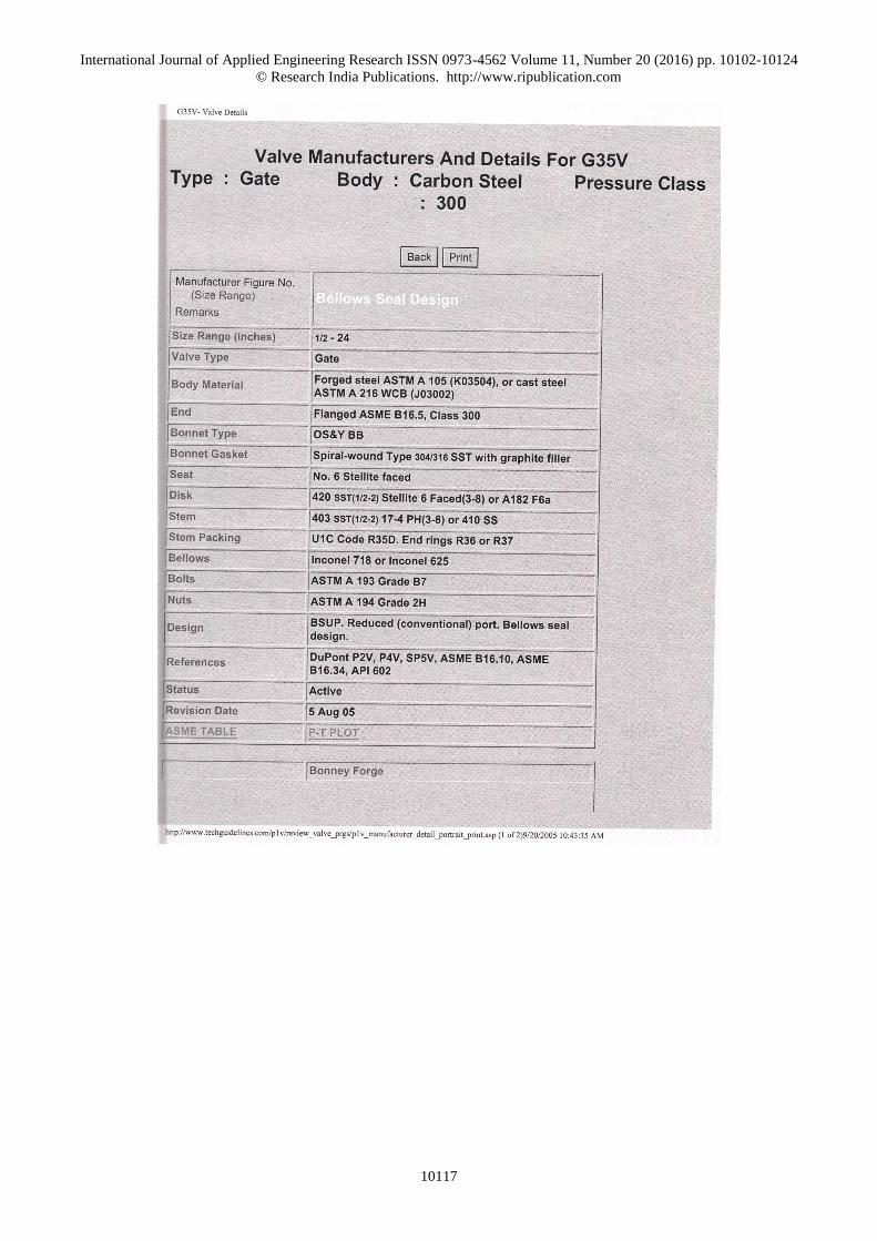
Valves: G37B Flanged gate valve or G35V Flanged gate valve. Valve
codes are described in Appendix II.
Gaskets for flanges: G63G4 (or) G63F4 flexattalic gaskets. Gasket codes are
described in the Appendix II.
Insulation: Type B or Type T or Type F insulation cover. Insulation
codes are described in Appendix II.
CONCLUSION
In this research work, the design of a hot oil heat exchanger
system has been considered. The heat exchanger employed in
the analysis is a concentric tube heat exchanger. Concentric
tube heat exchangers are regularly employed in process
industries and can be constructed by the technicians at the
process plant. A unique mathematical methodology was
presented for the design of a concentric tube heat exchanger.
Fundamental and widely accepted empirical expressions were
applied in the development of the mathematical heat
exchanger model. By applying this approach, the heat
exchanger’s length, flow velocity and diameter can be
determined iteratively. The proposed mathematical technique
is straightforward and can be readily applied for the design of
any concentric tube heat exchanger.
Thereafter, the required pumping system for the heat
exchanger was developed by employing DuPont engineering
standards. DuPont engineering standards are widely employed
in process industries around the globe, and these standards
provided the basis for the development of OSHA regulations.
Pump selection, pump head & flow rate calculations, material
selection for piping, fittings and insulation are detailed in this
document.
REFERENCES
[1] Silaipillayarputhur, K. and Idem, S., 2013, “A general
Matrix Approach to model steady state performance of
cross flow heat exchangers”, Heat Transfer
Engineering, Volume 34, Issue 4, page 338-348.
[2] Silaipillayarputhur, K. and Idem. S., 2013 “Practical
Validation of a Matrix Approach Steady State Heat
Exchanger Performance Model”, Journal of Applied
Global Research, ISSN: 1940-1841, Volume 6, Issue
17, page 1-22.
[3] Domingos, J. D. 1969. Analysis of Complex
Assemblies of Heat Exchangers, Int. J. Heat Mass
Transfer, Vol. 12, pp. 537-548.
[4] Pignotti, A. and Shah, R. K. 1992. Effectiveness-
number of transfer units relationships for heat
exchanger complex flow arrangements, Int. J. Heat
Mass Transfer, Vol. 35, No. 5, pp. 1275-1291.
[5] Shah, R. K. and Pignotti, A. 1993. Thermal Analysis of
Complex Crossflow Exchangers in Terms of Standard
Configurations, J. Heat Transfer, Vol. 115, pp. 353-
359.
[6] Navarro, H.A. and Cabezas-Gomez, L.C. 2007.
Effectiveness-NTU Computation with a Mathematical
Model for Cross-Flow Heat Exchangers, Brazilian J.
Chem. Eng., Vol. 24, No. 4, pp. 509-521.
[7] Cabezas-Gomez, L., Navarro, H.A., and Saiz-Jabardo,
J.M. 2007. Thermal Performance of Multipass Parallel

International Journal of Applied Engineering Research ISSN 0973-4562 Volume 11, Number 20 (2016) pp. 10102-10124
© Research India Publications. http://www.ripublication.com
10107
and Counter Cross-Flow Heat Exchangers, J. Heat
Transfer, Vol. 129, pp. 282-290.
[8] Silaipillayarputhur, K., Al-Muhaysh, K., and Al Yahya,
O., 2016, “Design of a Dowtherm A Pumping System”,
International Journal of Applied Engineering Research,
ISSN: 0973-4562, Volume 11, Issue 1, page 265-272,
Research India Publications, India.
[9] Fundamentals of Fluid Mechanics; 6th edition; Munson,
Okiishi and Huebsch; Wiley Inc., 2009; ISBN: 978-
0470-26284-9.
[10] Incropera F.P., Dewitt, D.P., Bergman, T.L., Lavine,
A.S., Fundamental of Heat and Mass Transfer. 4th
Edition. John Wiley & Sons, Inc., NY, 2006.
[11] DuPont Technology Consulting; E.I. Du Pont Nemours
Engineering Standards; 2002 revision.
[12] Material Safety Data Sheet (MSDS) Conoco Diamond
Class heat transfer fluids rated of open systems, Philips
66 lubrican

International Journal of Applied Engineering Research ISSN 0973-4562 Volume 11, Number 20 (2016) pp. 10102-10124
© Research India Publications. http://www.ripublication.com
10108
Appendix I
Inputs NPSH CalculationTank Pressure 75 psig
Diameter of Pipe D 0.021 m 5.10204082 barg
Length of pipe L 20.09 m 515306.122 N/m2
Velocity of hot oil V 1.81 m/s 69.0258301 m
Hot oil density ρ 761 kg/m3 Head Pressure 12 ft
Thermal conductivity k 0.13321 W/mK 3.66 m
Specific heat cp 2558.1 J/kg.K 27323.4006 N/m2
Kinematic viscosity ʋ 0.00000154 m2/s Vapor pressure of hot oil 0.078 psig
Flow rate Q 0.0006309 m3/s 0.00530612 barg
Mass flow rate mdot 0.48 kg/s 535.918367 N/m2
NPSH (A) (Tank Pr + Head Pr - Vapor Pr) 542093.605 N/m2
Diameter (in) 0.826771654 in 5.36726341 barg
Pipe size corresponding to pipe chart 3/4" 78.8987722 psig
Total Piping 50 m Pump is safe for operation as NPSH (A) > 25.0 psig
Pump ΔP Calculation
Total Piping 50 m Head loss due to 4 Elbows (minor loss) 0.20037309 m
Vertical piping 7 ft Head loss due to 6 Gate Valves (minor loss) 0.15027982 m
2.1336 m Head loss due to sudden expansion (minor loss) 0.16697757 m
Reynolds number Re 24681.81818 Head loss due to sudden contraction (minor loss) 0.08348879 m
Steel roughness ε1 0.000046 m Total minor losses 0.60111927 m
ε1/D 0.002190476 Total frictional head loss (major+minor) 11.5341747 m
f (from Moody chart) 0.0275 Total Head loss (total loss + vertical piping) 13.6677747 m
Frictional Head loss due to piping (major loss) 10.93305543 m
Pressure to overcome at inlet (tank pr + head pr) 72.6858301 m
Friction loss cofft - Elbow 0.3 Excess pressure desired at inlet (industry norm) 25 psig
Friction loss cofft - Gate Valve 0.15 for ease of entry back into the tank 1.70068027 barg
Friction loss cofft - Sudden Contraction 0.5 171768.707 N/m2
Friction loss cofft - Sudden Expansion 1 23.00861 m
# of Elbows 4 109.362215 m
# of Gate Valves 6 816433.772 N/m2
# of Sudden Expansion 1 8.0835027 barg
# of Sudden Contraction 1 118.82749 psig
Pump Inlet Pressure (Tank Pressure + Head Pressure) 72.6858301 m
Hence pump must develop (Dis. Pr - Inlet Pr) 36.6763847 m
120.329346 ft
273804.249 N/m2
2.71093316 barg
39.8507175 psig
Reqd Pump Dis. Pressure (Losses+Pr. To overcome+
Excess Pr. Desired)
Piping Calculations

International Journal of Applied Engineering Research ISSN 0973-4562 Volume 11, Number 20 (2016) pp. 10102-10124
© Research India Publications. http://www.ripublication.com
10109
Appendix II
Selection of Pipe, Fittings and Insulation:

International Journal of Applied Engineering Research ISSN 0973-4562 Volume 11, Number 20 (2016) pp. 10102-10124
© Research India Publications. http://www.ripublication.com
10110

International Journal of Applied Engineering Research ISSN 0973-4562 Volume 11, Number 20 (2016) pp. 10102-10124
© Research India Publications. http://www.ripublication.com
10111

International Journal of Applied Engineering Research ISSN 0973-4562 Volume 11, Number 20 (2016) pp. 10102-10124
© Research India Publications. http://www.ripublication.com
10112

International Journal of Applied Engineering Research ISSN 0973-4562 Volume 11, Number 20 (2016) pp. 10102-10124
© Research India Publications. http://www.ripublication.com
10113

International Journal of Applied Engineering Research ISSN 0973-4562 Volume 11, Number 20 (2016) pp. 10102-10124
© Research India Publications. http://www.ripublication.com
10114

International Journal of Applied Engineering Research ISSN 0973-4562 Volume 11, Number 20 (2016) pp. 10102-10124
© Research India Publications. http://www.ripublication.com
10115

International Journal of Applied Engineering Research ISSN 0973-4562 Volume 11, Number 20 (2016) pp. 10102-10124
© Research India Publications. http://www.ripublication.com
10116
International Journal of Applied Engineering Research ISSN 0973-4562 Volume 11, Number 20 (2016) pp. 10102-10124
© Research India Publications. http://www.ripublication.com
10117

International Journal of Applied Engineering Research ISSN 0973-4562 Volume 11, Number 20 (2016) pp. 10102-10124
© Research India Publications. http://www.ripublication.com
10118

International Journal of Applied Engineering Research ISSN 0973-4562 Volume 11, Number 20 (2016) pp. 10102-10124
© Research India Publications. http://www.ripublication.com
10119

International Journal of Applied Engineering Research ISSN 0973-4562 Volume 11, Number 20 (2016) pp. 10102-10124
© Research India Publications. http://www.ripublication.com
10120

International Journal of Applied Engineering Research ISSN 0973-4562 Volume 11, Number 20 (2016) pp. 10102-10124
© Research India Publications. http://www.ripublication.com
10121

International Journal of Applied Engineering Research ISSN 0973-4562 Volume 11, Number 20 (2016) pp. 10102-10124
© Research India Publications. http://www.ripublication.com
10122
International Journal of Applied Engineering Research ISSN 0973-4562 Volume 11, Number 20 (2016) pp. 10102-10124
© Research India Publications. http://www.ripublication.com
10123

International Journal of Applied Engineering Research ISSN 0973-4562 Volume 11, Number 20 (2016) pp. 10102-10124
© Research India Publications. http://www.ripublication.com
10124