design elements of airport taxiway
TRANSCRIPT
Design Elements Of Taxiway
Asok DACHARLAM.TECH – 1ST
YEARGMR Institute Of Technology
Taxiway
Taxiways are defines as paths on the airfield surface for the taxing of aircraft and are intended to provide linkage between one part of the airfield and another.
Aircraft movement on taxiways are essentially ground movements and are relatively slow compared with runway moments.
Taxiway
Apron taxiway Located on the periphery of an apron to provide uninterrupted
taxing of aircraft across the apron.
Dual parallel taxiway Two parallel taxiways on which aircraft can taxi in opposite
directions.
Terminal taxi lane It is a portion of an apron intended to provide access to only aircraft
stands or gate positions.
Taxiway Factors controlling the layout
Taxiway should be so arranged that the aircrafts which have just landed and moving towards the apron, do not interfere with the aircrafts taxiing for take-off.
Taxiway should be located at various points along the runway so that the landing aircraft leaves the runway as early as possible. Such taxiway are called “exit taxiway”
Shortest practicable distance between terminal building and end of take-off runway.
Taxiway – Geometric
Length Longitudinal gradient Rate of change of longitudinal gradient Width of taxiway Sight distance Transverse gradient Width of safety area Turing radius
length of Taxiway:
It should be as short as possible. No specifications are recommended by any organization.
Longitudinal gradient
Level taxiways are operationally more desirable. If gradient is steep it affects fuel consumption. As per ICAO, maximum longitudinal gradient is
3% for A and B type of airports and 1.5% for C,D and E type of airports.
Rate of change of longitudinal gradient
Available sight distance on the pavement is affected by rate of change of longitudinal gradient.
As per ICAO the maximum change in pavement longitudinal gradient is 4% for A and B category of airports and 3.33% for C, D and E category of airports.
Rate of change should be smooth enough not to cause any problem to aircraft movement.
Vertical curves are provided at such junctions.
Rate of change of longitudinal gradient
For airports with code letters A and B, ICAO recommends length of vertical curve as 25m for each 1% grade change.
For airports with code letter C, D and E, ICAO recommended length of vertical curve as 30m for each 1% grade change.
FAA recommends distance between points of grade change as:
30 |(A+B)| m
Where, A and B are the percent grade changes at the two points of grade changes along the centerline of taxiway.
Width of taxiway
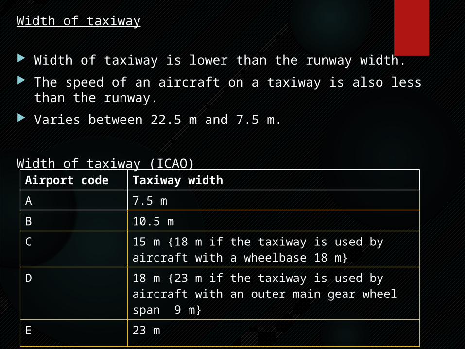
Width of taxiway is lower than the runway width. The speed of an aircraft on a taxiway is also less than the runway. Varies between 22.5 m and 7.5 m.
Width of taxiway (ICAO)
Airport code Taxiway widthA 7.5 mB 10.5 mC 15 m {18 m if the taxiway is used by aircraft
with a wheelbase 18 m}D 18 m {23 m if the taxiway is used by aircraft
with an outer main gear wheel span 9 m}
E 23 m
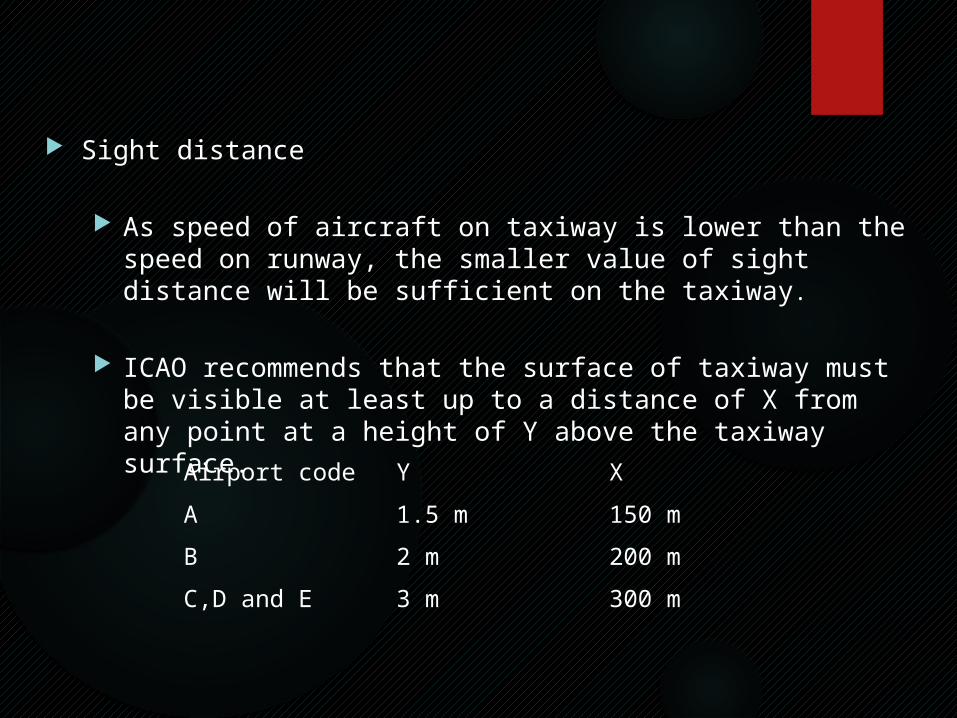
Sight distance
As speed of aircraft on taxiway is lower than the speed on runway, the smaller value of sight distance will be sufficient on the taxiway.
ICAO recommends that the surface of taxiway must be visible at least up to a distance of X from any point at a height of Y above the taxiway surface.
Airport code Y XA 1.5 m 150 mB 2 m 200 mC,D and E 3 m 300 m
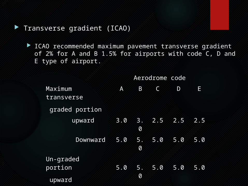
Transverse gradient (ICAO)
ICAO recommended maximum pavement transverse gradient of 2% for A and B 1.5% for airports with code C, D and E type of airport.
Aerodrome codeMaximum transverse graded portion
A B C D E
upward 3.0 3.0 2.5 2.5 2.5
Downward 5.0 5.0 5.0 5.0 5.0
Un-graded portion upward 5.0 5.0 5.0 5.0 5.0
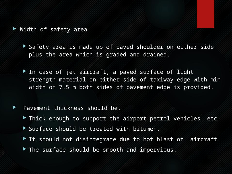
Width of safety area
Safety area is made up of paved shoulder on either side plus the area which is graded and drained.
In case of jet aircraft, a paved surface of light strength material on either side of taxiway edge with min width of 7.5 m both sides of pavement edge is provided.
Pavement thickness should be, Thick enough to support the airport petrol vehicles, etc. Surface should be treated with bitumen. It should not disintegrate due to hot blast of aircraft. The surface should be smooth and impervious.
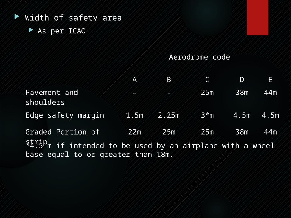
Width of safety area As per ICAO
Aerodrome code
A B C D EPavement and shoulders
- - 25m 38m 44m
Edge safety margin 1.5m 2.25m 3*m 4.5m 4.5m
Graded Portion of strip 22m 25m 25m 38m 44m
*4.5 m if intended to be used by an airplane with a wheel base equal to or greater than 18m.
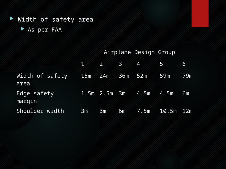
Width of safety area As per FAA
Airplane Design Group1 2 3 4 5 6
Width of safety area 15m 24m 36m 52m 59m 79mEdge safety margin 1.5
m2.5m 3m 4.5m 4.5m 6m
Shoulder width 3m 3m 6m 7.5m 10.5m 12m
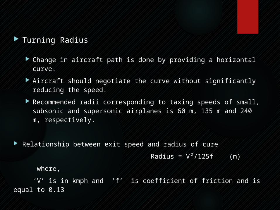
Turning Radius
Change in aircraft path is done by providing a horizontal curve. Aircraft should negotiate the curve without significantly reducing the
speed. Recommended radii corresponding to taxing speeds of small, subsonic
and supersonic airplanes is 60 m, 135 m and 240 m, respectively.
Relationship between exit speed and radius of cure
Radius = V²/125f (m)
where,
‘V’ is in kmph and ‘f’ is coefficient of friction and is equal to 0.13
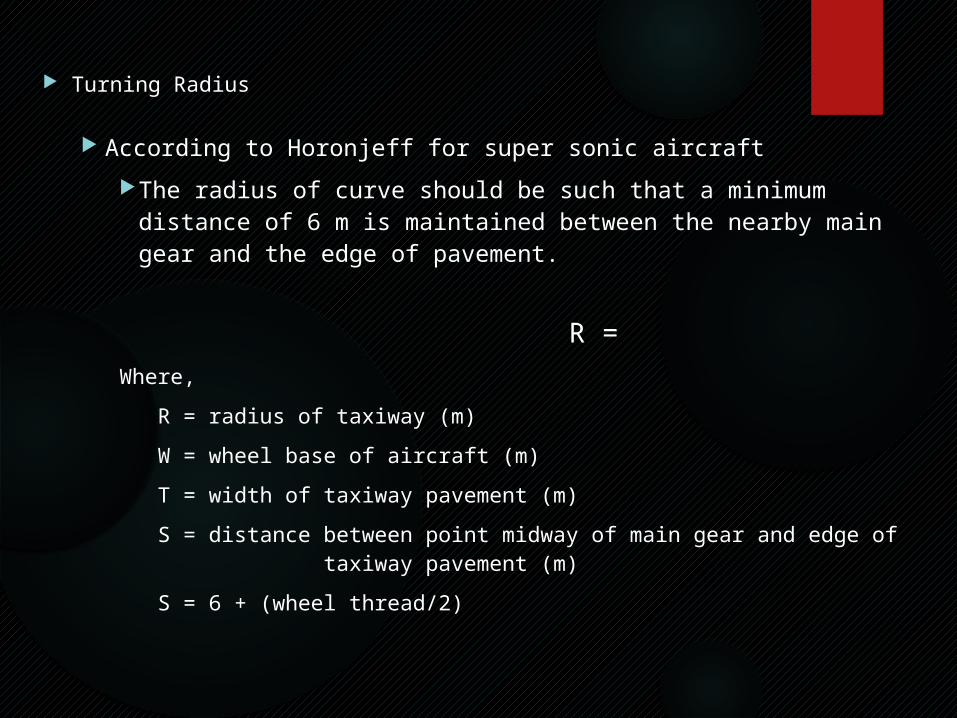
Turning Radius
According to Horonjeff for super sonic aircraft The radius of curve should be such that a minimum distance of 6 m is
maintained between the nearby main gear and the edge of pavement.
R = Where, R = radius of taxiway (m)
W = wheel base of aircraft (m)
T = width of taxiway pavement (m)
S = distance between point midway of main gear and edge of taxiway pavement (m)
S = 6 + (wheel thread/2)
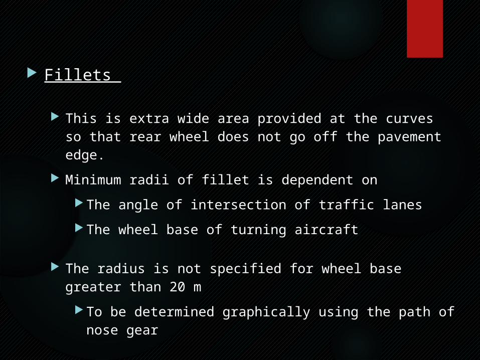
Fillets
This is extra wide area provided at the curves so that rear wheel does not go off the pavement edge.
Minimum radii of fillet is dependent on The angle of intersection of traffic lanes The wheel base of turning aircraft
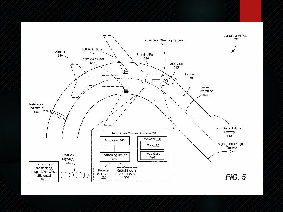
The radius is not specified for wheel base greater than 20 m To be determined graphically using the path of nose gear
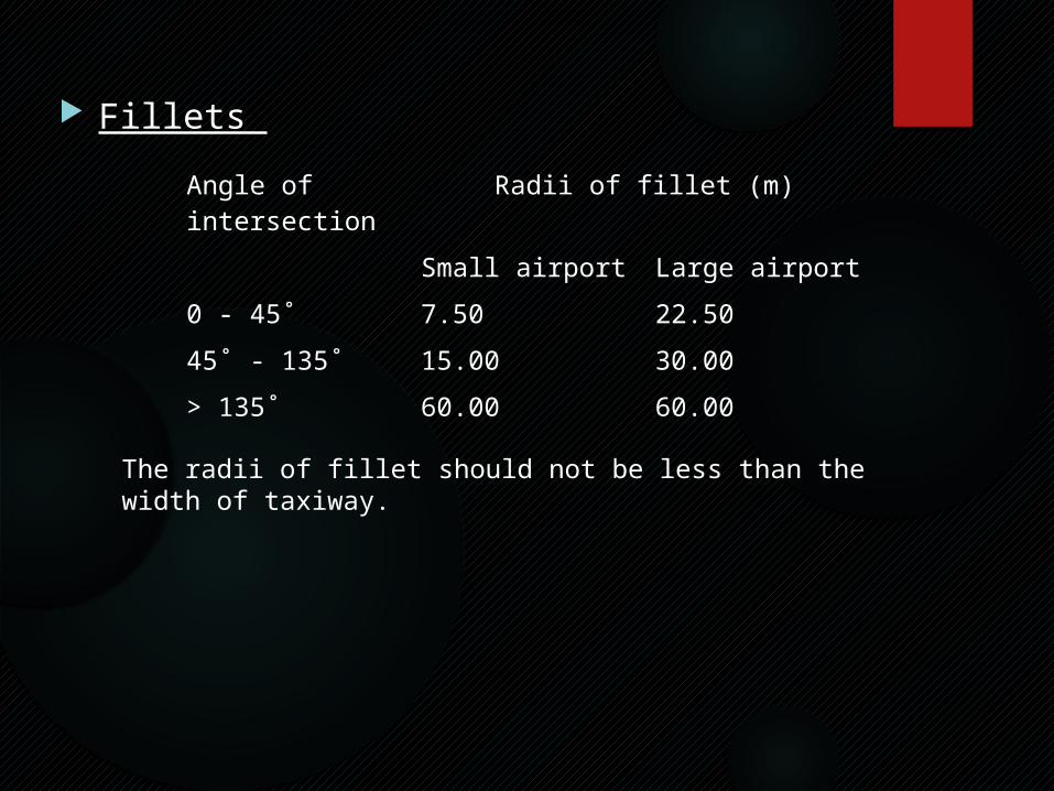
Fillets Angle of
intersectionRadii of fillet (m)
Small airport Large airport0 - 45˚ 7.50 22.5045˚ - 135˚ 15.00 30.00> 135˚ 60.00 60.00
The radii of fillet should not be less than the width of taxiway.
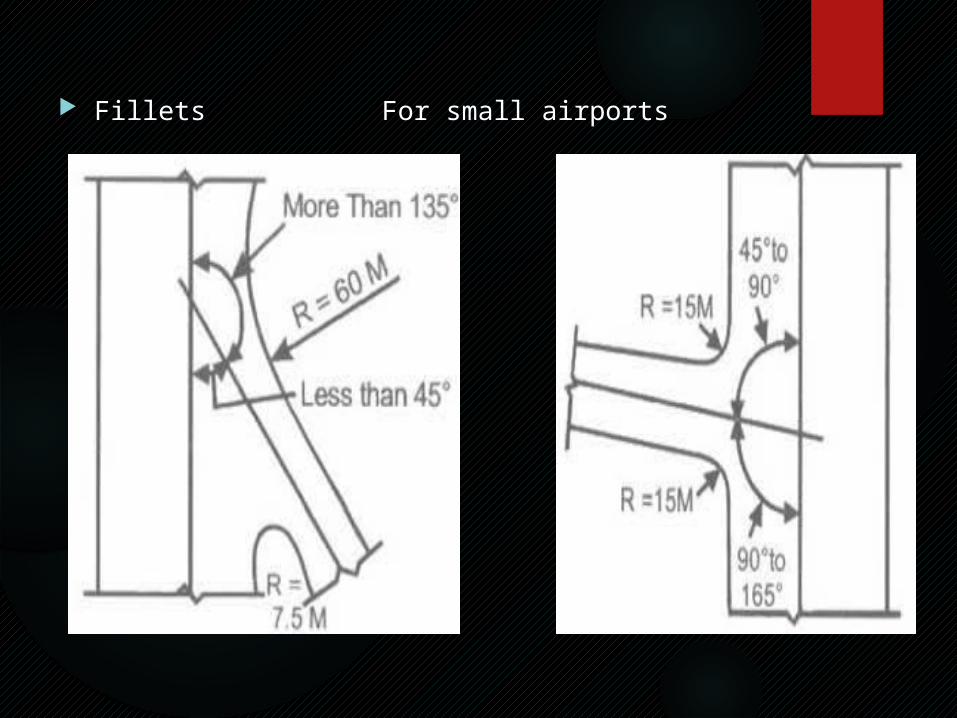
Fillets For small airports
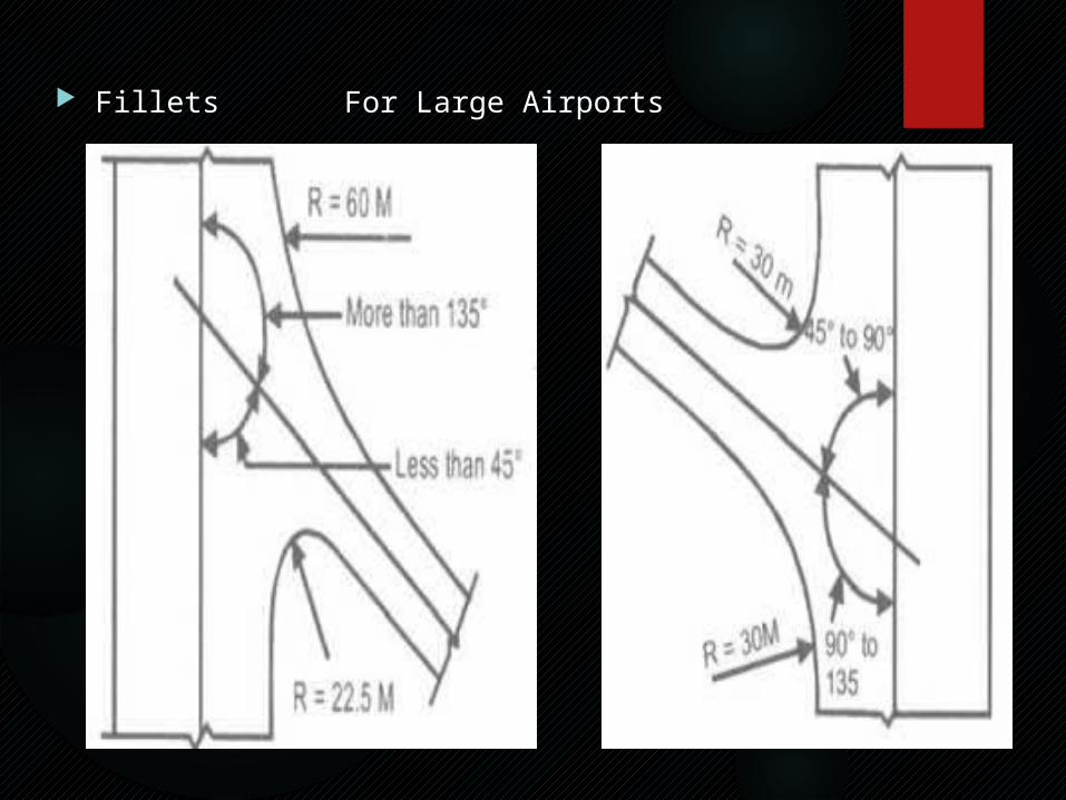
Fillets For Large Airports
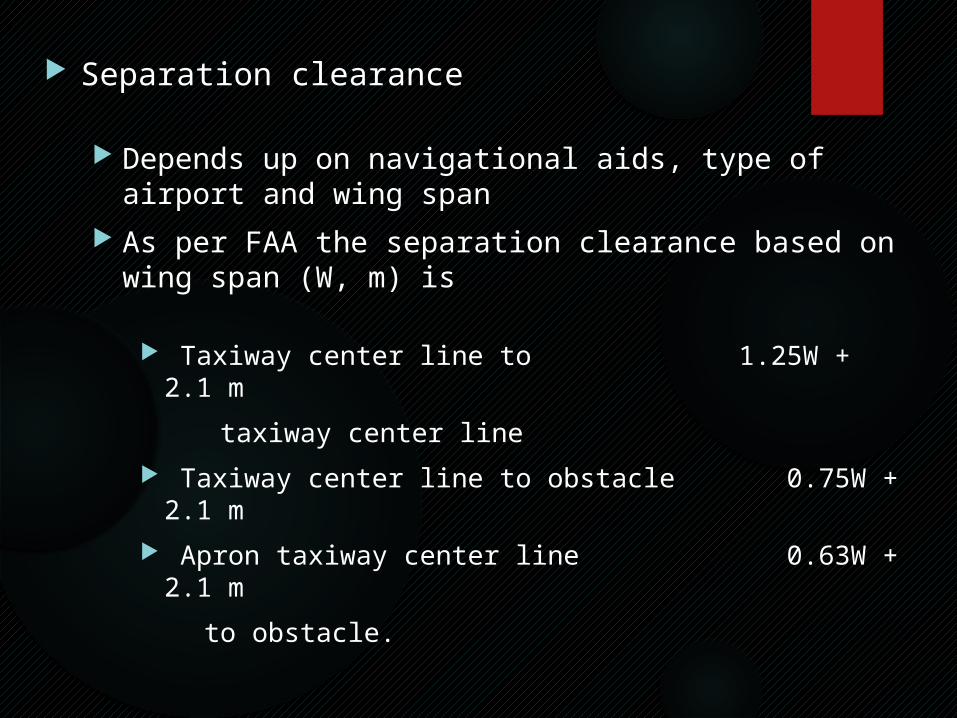
Separation clearance
Depends up on navigational aids, type of airport and wing span As per FAA the separation clearance based on wing span (W, m) is
Taxiway center line to 1.25W + 2.1 m
taxiway center line Taxiway center line to obstacle 0.75W + 2.1 m Apron taxiway center line 0.63W
+ 2.1 m
to obstacle.
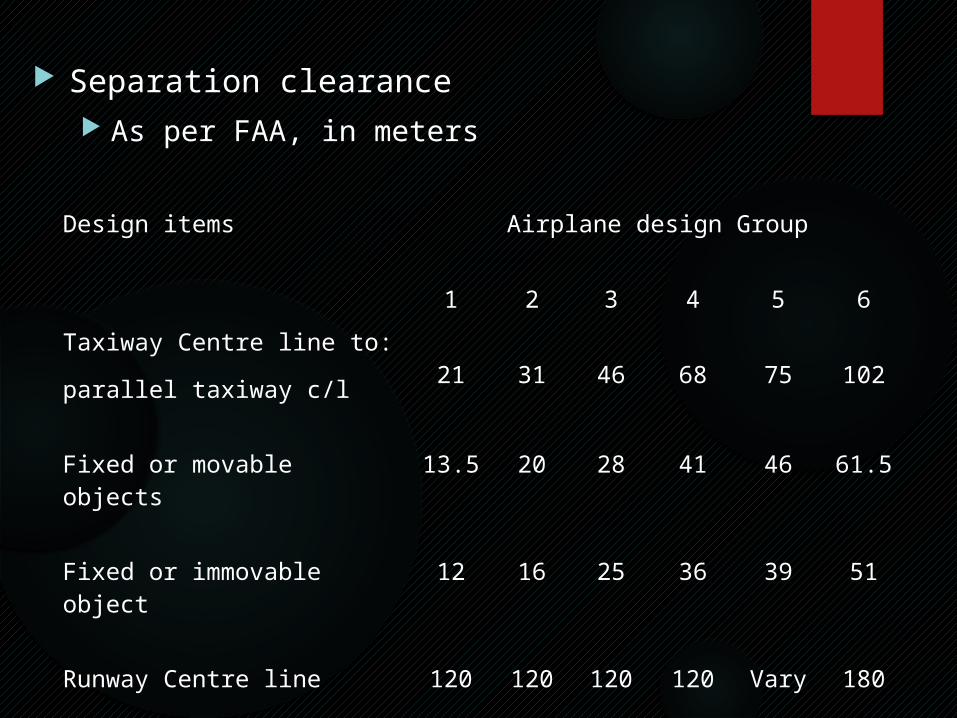
Separation clearance As per FAA, in meters
Design items Airplane design Group
1 2 3 4 5 6Taxiway Centre line to:parallel taxiway c/l 21
31 46 68 75 102
Fixed or movable objects 13.5 20 28 41 46 61.5 Fixed or immovable object 12 16 25 36 39 51 Runway Centre line 120 120 120 120 Vary 180
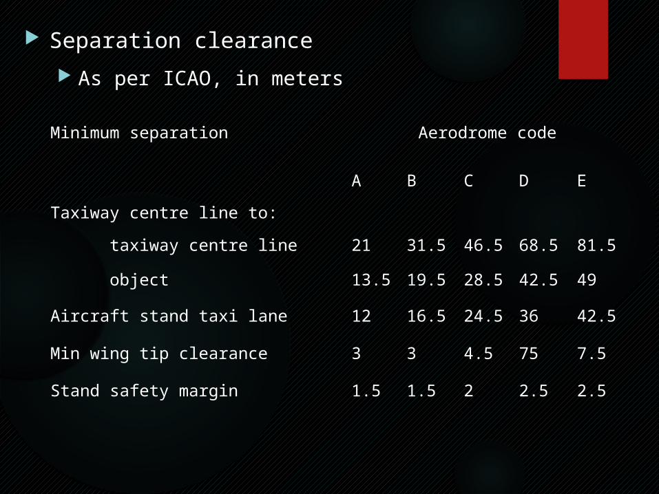
Separation clearance As per ICAO, in meters
Minimum separation Aerodrome code
A B C D ETaxiway centre line to: taxiway centre line 21 31.5 46.5 68.5 81.5
object 13.5 19.5 28.5 42.5 49
Aircraft stand taxi lane 12 16.5 24.5 36 42.5
Min wing tip clearance 3 3 4.5 75 7.5
Stand safety margin 1.5 1.5 2 2.5 2.5
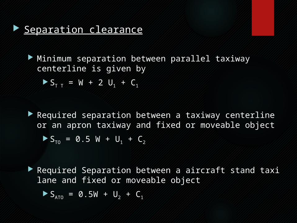
Separation clearance
Minimum separation between parallel taxiway centerline is given by ST T = W + 2 U1 + C1
Required separation between a taxiway centerline or an apron taxiway and fixed or moveable object
STO = 0.5 W + U1 + C2
Required Separation between a aircraft stand taxi lane and fixed or moveable object
SATO = 0.5W + U2 + C1
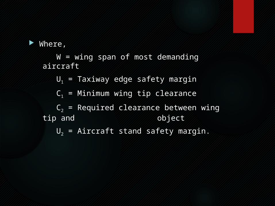
Where,
W = wing span of most demanding aircraft
U1 = Taxiway edge safety margin
C1 = Minimum wing tip clearance
C2 = Required clearance between wing tip and object
U2 = Aircraft stand safety margin.
References NPTEL video lecture “PLANNING & DESIGN OF AIRPORTS” by ROBERT
HORONJEFF, FRANCIS X. MCKELVEY. WILLIAM J. SPROULE. SETH B.YOUNG

Thank you