design, development and modeling of a solar distillation ...nbn:de:hebis:... · universität kassel...
TRANSCRIPT
FORSCHUNGSBERICHT AGRARTECHNIK des Fachausschusses Forschung und Lehre der Max-Eyth-Gesellschaft Agrartechnik im VDI (VDI-MEG) 492
Anjum Munir
Design, development and modeling of a solar distillation system for the processing of medicinal and aromatic plants
Dissertation Witzenhausen 2010
Universität Kassel / Witzenhausen
Fachbereich Ökologische Agrarwissenschaften Fachgebiet Agrartechnik Prof. Dr. Oliver Hensel
Design, development and modeling of a solar distillation system for the processing of medicinal and
aromatic plants
Dissertation zur Erlangung des akademischen Grades Doktor der Agrarwissenschaften
von M.Sc. Ing. Anjum Munir
aus Faisalabad, Pakistan
2010
Die vorliegende Arbeit wurde vom Fachbereich Ökologische Agrarwissenschaften der Universität Kassel als Dissertation zur Erlangung des akademischen Grades “Doktor der Agrarwissenschaften” angenommen. Tag der mündlichen Prüfung: 22.07.2010 Erster Gutachter : Prof. Dr. Oliver Hensel Zweiter Gutachter : Prof. Dr. Klaus Vajen Mündlicher Prüfer: Prof. Dr. Jürgen Heß PD Dr. Jens Gebauer
Alle Rechte vorbehalten. Die Verwendung von Texten und Bildern, auch auszugsweise, ist ohne Zustimmung des Autors urheberrechtswidrig und strafbar. Das gilt insbesondere für Vervielfältigung, Übersetzung, Mikroverfilmung sowie die Einspeicherung und Verarbeitung in elektronischen Systemen. © 2010 Im Selbstverlag: Anjum Munir Bezugsquelle: Universität Kassel, FB Ökologische Agrarwissenschaften
Fachgebiet Agrartechnik Nordbahnhofstr. 1a 37213 Witzenhausen

Acknowledgements The work presented in this manuscript was accomplished under the inspiring guidance and
dynamic supervision of Prof. Dr. Oliver Hensel, Institute of Agricultural Engineering,
University of Kassel, Germany. His critical comments and useful suggestions during my
Ph.D studies were very simulating to focus on my objectives. His constant help, keen
interest and sympathetic attitude during the experiments and the preparation of this thesis
are gratefully acknowledged.
The author takes an opportunity to express his heartiest thanks to Prof. Dr. Klaus Vajen,
Institute of “Solar and system engineering” University of Kassel, Germany as a member of
his supervisory committee for his sincere advice, valued criticism, and suggestions had
been of much value during the preparation of this manuscript.
With the high emotion of benevolence and gratitude from the deepest core of my heart, I
record my sincerest feelings of obligation to Mr. Wolfgang Scheffler and Mrs. Heike Hoedt
“Solare Brücke Organization” who encouraged and provided me necessary facilities
throughout the course of this investigation and writing of this manuscript. My sincere
appreciations are also extended to Mr. Behringer, International Solar Food Processing
Network, for his kind help during the development work of my project. I am deeply grateful
to Higher Education Commission (HEC) of Pakistan, German Academic Exchange Service
(DAAD) and University of Agriculture, Faisalabad, Pakistan for providing me an opportunity
and finance for achieving quality education in Germany.
Deepest appreciations are due to all the team of Agricultural Engineering especially
Christian Schellert, Heiko Tostmann, Uwe Richter, and Anne Noetzel for helping me and
making available the research facilities and valuable advice. I would like to express my
gratitude to Mrs. Monika Klaus to solve my academic and non-academic problems during
my Ph.D studies. I cannot forget Florent Dupont and Salvatore Grigoli who worked in our
project and helped me on many occasions. I would like to extend my special thanks to my
friends, Farhan Saeed, Shafique Maqsood, M. Sohail, Sultan Mahmood, M. Qasim and
Zaighum Zia for their moral support, inspiring guidance and encouragement during the
course study.
I don’t have suitable words in my command to acknowledge my family members especially
my mother, wife, brother, sisters and children for their patience and best wishes which
boosted my moral high to accomplish my goals. I dedicate the dissertation to my Late
father Ch. Munir Ahmad who left me on the way with a desire to see me a highly educated
person.

Table of Contents
Table of Contents .......................................................................................................... i
List of Figures .............................................................................................................. iv
1 Introduction ........................................................................................................... 1
Objectives of the studies .......................................................................................... 5
2 State of the art ...................................................................................................... 7
2.1 Production of herbs and medicinal plants ...................................................... 7
2.1.1 Medicinal plants in Pakistan ................................................................... 7
2.1.2 Drying of medicinal and aromatic plants ................................................. 9
2.1.3 Influence of drying temperature on active ingredients .......................... 10
2.2 Essential oils extraction from medicinal and aromatic plants ....................... 10
2.2.1 General ................................................................................................. 10
2.2.2 Essential oils extraction by distillation ................................................... 11
2.2.3 Industrial utilization of essential oils ...................................................... 17
2.2.4 Economic importance of the industry .................................................... 18
2.2.5 Essential oils in local and regional health care markets ........................ 19
2.2.6 Value addition in developing countries ................................................. 20
2.2.7 Problems and prospective for aromatherapy in tropical counties ......... 21
2.2.8 Different distillation plants for commercial applications ......................... 21
2.2.9 Guidelines during distillation ................................................................. 23
2.2.10 Distillation options ................................................................................. 24
2.3 Solar energy utilization ................................................................................. 25
2.3.1 Solar energy application in medium temperature range ....................... 25
2.3.2 Solar energy for industrial process heat demand ................................. 28
2.3.3 Evaluation of solar cookers ................................................................... 29
2.3.4 Use of high reflectivity material for the reflectors .................................. 30
2.3.5 Solar concentrators ............................................................................... 30
2.3.6 Solar distillation of water ....................................................................... 31
2.4 Auxiliary energy utilization in solar distillation system .................................. 32
3 Material and methods ......................................................................................... 33
3.1 Laboratory experiments ............................................................................... 33
3.2 Selection of the solar collector ..................................................................... 34
3.3 Development of Solar distillation system ..................................................... 35
ii
3.3.1 Description of Scheffler reflector for solar distillation system ............... 36
3.3.2 Use of secondary reflector for water and steam distillation .................. 37
3.3.3 Fabrication of the still for solar distillation system ................................ 39
3.3.4 Fabrication of condenser ...................................................................... 41
3.3.5 Florentine vessel or oil separator ......................................................... 41
3.4 Experimental set up and data acquisition .................................................... 42
3.5 Operational procedure of the solar distillation system ................................. 44
3.6 Mathematical modeling of solar distillation system ...................................... 45
3.7 Biomass energy utilization in solar distillation system ................................. 45
4 Results & discussions ........................................................................................ 47
4.1 Laboratory experiments............................................................................... 47
4.2 Design principle and mathematical calculations of Scheffler concentrator .. 50
4.2.1 Design of reflector parabola and reflector elliptical frame .................... 50
4.2.2 Distribution of crossbars on the reflector frame .................................... 55
4.2.3 Calculation of equations for the crossbars ellipses .............................. 56
4.2.4 Calculation of depths and arc lengths for different crossbars ............... 59
4.2.5 Installation of the Scheffler reflector on site ......................................... 62
4.2.6 Daily tracking ....................................................................................... 63
4.2.7 Calculation of seasonal parabola equations ......................................... 64
4.3 Calculation of the required size of the Scheffler reflector ............................ 72
4.4 Energy distribution in the solar distillation system ....................................... 74
4.4.1 Available insolation from Primary reflector ........................................... 75
4.4.2 Energy distribution at primary reflector ................................................. 78
4.4.3 Energy distribution at secondary reflector ............................................ 79
4.4.4 Energy losses from the distillation unit ................................................. 80
4.5 Thermal losses calculation of the distillation still ......................................... 81
4.5.1 Conduction and convection losses ....................................................... 81
4.5.2 Radiation losses ................................................................................... 83
4.5.3 Determination of natural convection co-efficient .................................. 83
4.5.4 Parameters of the existing prototype of the distillation still ................... 85
4.6 Mathematical model for the solar distillation system ................................... 86
4.7 Output of the mathematical model for the solar distillation system .............. 93
Energy available for the solar distillation system ................................................ 97
4.8 Performance evaluation of the solar distillation system ............................... 98
Determination of dryness fraction ....................................................................... 98
iii
4.9 Evaluation of Scheffler reflector by steam receiver .................................... 102
4.10 Essential oil extraction by solar distillation ................................................. 104
4.10.1 Distillation experiments with Lemon Balm (Melissa officinalis L.) ....... 108
4.10.2 Oregano (Origanum vulgare SSP.) ..................................................... 114
4.10.3 Cloves (Eugenia caryophyllata) .......................................................... 117
4.10.4 Cumin (Cuminum cyminum) ............................................................... 119
4.10.5 Rosemary (Rosmarinus officinalis) ..................................................... 120
4.10.6 Fennel (Foeniculum valgure Mill.) ....................................................... 122
4.11 Comparison of results-laboratory versus solar ........................................... 124
4.12 Need of auxiliary energy for the solar distillation system ........................... 125
4.12.1 Distillation experiments with solar-biomass hybrid system ................ 126
5 Overall discussion ............................................................................................. 132
6 Outlook.............................................................................................................. 139
7 Recommendations and suggestions ................................................................. 140
8 Summary ........................................................................................................... 141
Zusammenfassung ................................................................................................... 143
Literature Cited ......................................................................................................... 145
Appendices .............................................................................................................. 154
iv
List of Figures
Figure 2.1 Flow diagram of water distillation process ................................................... 14
Figure 2.2 Flow diagram of water and steam distillation process ................................. 15
Figure 2.3 Flow diagram of direct steam distillation process ........................................ 17
Figure 3.1 Laboratory distillation apparatus ………………………………………………..34
Figure 3.2 Secondary reflector for solar distillation system .......................................... 38
Figure 3.3 Separator types ........................................................................................... 42
Figure 3.4 Schematic of solar distillation system ........................................................... 43
Figure 3.5 Solar-biomass hybrid system for distillation of essential oils ........................ 46
Figure 4.1 Process curves of different plant materials for laboratory experiments….… 47
Figure 4.2 Heat energy required (kW h) per 100 grams of different plant materials ...... 49
Figure 4.3 Heat energy required per ml of essential oil for different plant materials...... 49
Figure 4.4 Section of the Scheffler reflector in a paraboloid .......................................... 51
Figure 4.5 Description of parabola of the Scheffler reflector ......................................... 52
Figure 4.6 Intersections points of seven crossbars (q1 to q7) ....................................... 56
Figure 4.7 Description of the Scheffler reflector and the crossbars .............................. 57
Figure 4.8 Ellipse of the crossbar for the Scheffler reflector .......................................... 60
Figure 4.9 Radius, depth and arc length details for nth crossbar .................................. 60
Figure 4.10 Installation and daily tracking details of the Scheffler reflector ..................... 63
Figure 4.11 Schematic of photovoltaic daily tracking system .......................................... 64
Figure 4.12 Seasonal parabola equations for an 8 m2 Scheffler reflector ...................... 67
Figure 4.13 Detail of pivot points and telescopic clamps of the Scheffler reflector .......... 69
Figure 4.14 Effect of pivot points on reflector deformation ............................................. 70
Figure 4.15 Functioning of pivot points and clamps to deform the reflector .................... 71
Figure 4.16 Explanation of available energy and losses in a solar distillation system ..... 75
Figure 4.17 Variation of solar declination and aperture area for standings reflectors...... 77
Figure 4.18 Variation of solar declination and aperture area for laying reflectors ........... 78
Figure 4.19 Description of the solar distillation model ..................................................... 86
Figure 4.20 Predicted values of energy distribution in the northern hemisphere ............ 93
Figure 4.21 Predicted values of energy distribution in the southern hemisphere ........... 94
Figure 4.22 Predicted values of heat losses from the distillation still .............................. 95
Figure 4.23 Heat losses at different parts of the distillation still ....................................... 96
v
Figure 4.24 Total energy available (modeled values) at the primary reflector and for the
distillation process ............................................................................................................ 97
Figure 4.25 Performance evaluation of solar distillation system (on Aug, 31 2008 with
20 liters of water, 30 readings averaged) ........................................................................ 101
Figure 4.26 Infrared photos of the bottom and top part of the solar distillation still .... 102
Figure 4.27 Details of steam receiver installation ..................................................... 103
Figure 4.28 Experimental set up of the steam receiver ............................................ 103
Figure 4.29 Detail of water and steam tests with and without secondary reflector .... 104
Figure 4.30 Experimental (dotted) and regression curves for percentage of essential
oils extracted against different heat energy during solar distillation ................................ 106
Figure 4.31 Process curves for fresh, dry and chopped Lemon Balm ...................... 110
Figure 4.32 Comparison of fresh, chopped and dry Melissa .................................... 111
Figure 4.33 Process curved of Peppermint verities (Mentha piperita L, Mentha spec.,
and Mentha spicala) ....................................................................................................... 113
Figure 4.34 Comparison of Peppermint varieties ..................................................... 114
Figure 4.35 Process comparison for chopped and un-chopped Oregano ................ 115
Figure 4.36 Comparison for chopped and un-chopped Oregano ............................. 116
Figure 4.37 Experimental results for the essential oils extracted against different heat
energy during solar distillation of Cloves ........................................................................ 118
Figure 4.38 Experimental results for the essential oils extracted against different heat
energy during solar distillation of Cumin ........................................................................ 120
Figure 4.39 Experimental results for the essential oils extracted against different heat
energy during solar distillation of Rosemary .................................................................. 122
Figure 4.40 Experimental results for the essential oils extracted against different heat
energy during solar distillation of Fennel ........................................................................ 123
Figure 4.41 Water temperature and beam radiations (max.) during distillation
experimentse (Witzenhausen, Latitute:51.3°) ................................................................ 125
Figure 4.42 Distillation still with coils and steam connections .................................. 126
Figure 4.43 Process comparison for solar and solar-biomass hybrid system ........... 128
Figure 4.44 Comparison of chopped and un-chopped European Silver Fir .............. 129
Figure 4.45 Results of solar-biomass hybrid distillation system ............................... 130
Figure 4.46 Schematic diagram of solar-biomass hybrid system ............................. 131

1 Introduction With the increasing population and industrialization, there is need to cut down the load of
fossil fuels and to reduce environmental pollution. Unlike conventional energy utilization,
solar energy is free of connections, unlimited supply of source and also decease gas
emission. Solar energy investments in developing countries are imperative to avoid an
energy crisis arising from over-dependence on fossil fuels. The situation is critical because
fossil fuels are finite and fast depleting (Okoro, 2004). Various industrial surveys show that
up to 24 percent of all industrial heat, directly used in the processes, is at temperatures
from ambient to 180 °C. In several industries, 100 percent process heat requirement is
below 180 °C which can be supplied economically by evacuated tube collectors and solar
concentrators (Garg & Prakash, 2006). From a number of studies on industrial heat
demand, several industrial sectors have been identified with favorable conditions for the
application of solar energy. The most important industrial processes using heat at mean
temperature level are: sterilizing, extraction, pasteurizing, drying, solar cooling and air
conditioning, hydrolyzing, distillation and evaporation, washing and cleaning, and
polymerization. The ranges of all these processes lie between 60-280 °C (Kalogirou,
2003). Most of the agro-based industries can be operated in this medium temperature
range. The use of solar energy in agriculture sector can be used to process many
perishable agricultural products at farm level. At present, various kinds of solar collectors
are in use in the sector of agriculture and post harvest technology, yet their applications
are restricted only to drying and warming water etc. Beyond this low temperature
applications there are several potential fields of application of solar thermal energy at a
medium and medium-high temperature level. Many important developments have occurred
in solar concentrating systems for diverse applications in the last decades. In particular, an
important research effort has been directed towards power generation applications,
chemical systems, and process heat (Estrada, 2007). Tremendous efforts have been
made in areas of application of solar energy in the agricultural sector. This can be seen in
areas of solar water heating for dairy and micro irrigation (Oparaku 1991; Jenkins 1995;
Essandu-Yeddu 1993). The promotion of small scale agro-based industries by using
innovative solar collectors can open new landmarks in rural development especially in
tropical countries.
Medicinal plants have been used for different purposes in many regions of the world since
ancient times. After World Health Organizations (WHO), medicinal plants are commonly
2
used in preventing and treating specific ailments and diseases and are generally
considered to play a beneficial role in health care. Some cultivars from medicinal plant
families are also used as ingredients to season or to give a pleasant flavor or smell to
foods. Therefore, the terms “medicinal” and “aromatic” are usually used in conjunction.
Essential oils extraction from medicinal and aromatic plants is one of the medium
temperature agro-based industries. These oils are used in medicinal and pharmaceutical
purposes, food and food ingredients, herbal tea, cosmetics, perfumery, aromatherapy,
pest, and disease control, dying in textiles, gelling agents, plant growth regulators, and
paper making (Öztekin & Martinov, 2007). A single ounce of most of the oils is worth
thousands of Dollars. In the last decade, these oils remedies have gained enormous
popularity in industrialized countries as well particularly in the multi-million-dollar
aromatherapy business. Out of all extraction methods, the distillation methods have
advantages of extracting pure and refine essential oils by evaporating the volatile essence
of the plant material (Malle & Schmickl, 2005). At present, there are large and centralized
distillation units mostly located in city areas. Due to their high operating costs, these are
sometimes unmanageable by farmers or even groups of farmers in most of the developing
countries. Further, some essential oils come from extremely delicate flowers and leaves
that must be processed soon after harvesting. Thus, for functional, economic and
environmental reasons, there is need of a decentralized distillation system. Due to lack of
adequate facilities for the decentralized distillation systems, farmers prefer to dry their
product rather to sell it at very low price. Results show that conventional drying methods
such as open sun drying and conventional-fuel dryers are not suitable which deteriorate
the essential oils components in the herbs. Moreover, the drying process necessitates an
enormous amount of thermal and electrical energy (Fargali, 2008). The on-farm solar
distillation is a decentralized approach to reduce the post harvest losses and to prevent
spoilage of essential oil components by processing the fresh herbs. Examples of the plants
are Peppermint, Lemon Balm (Melissa), Lavender, Cumin, Cloves, Anise, Rosemarie,
Patchouli, Caraway, Cassia, Oregano, European Silver Fir, and Fennel etc.
In order to run the distillation experiments, boiling, cooking and steam generation are the
basic requirements. Increasing awareness of the growing global need for alternative
cooking fuels has resulted in an expansion of solar cooker research and development
(Funk, 2000). A system for solar process heat for decentralized applications in developing
countries was presented by Spate et al. (1999). The system is suitable for community
3
kitchens, bakeries and post harvest treatment. The system employs a fix focused parabola
collector, a high temperature flat plate collector and pebble-bed oil storage.
Decreasing the area from which the heat losses occur can increase energy delivery
temperatures. With higher a concentration ratio, there is an increase in temperature at
which heat is delivered due to an increase in flux intensity and a decrease in the receiver
area. Modern parabola trough concentrators and central receiver towers are operated by
high-tech computer programmed tracking system and are used only in large scale
applications to justify the high investment costs and gross over design. The conventional
paraboloidal concentrators converge all the beam radiations at the focus and are selected
as the bottom part of a paraboloid parallel to the directrix. With such parabolic
concentrators, not only the frequent tracking of two axes is required but also the receiver is
fixed at the focal point as an integral part of the reflector. Moreover, focus lies in the path
of incident beam radiations. Despite the high temperature output, such types of
concentrators are rarely used for industrial applications due to frequent changes of the
focus position and inadequacy of handling approach at the receiver. This limitation,
however, is solved by the Scheffler fixed focus concentrator which not only provides
simple and precise automatic tracking but also a fixed focus away from the path of incident
beam radiations. This design also provides an opportunity to shift the receiver for indoor
applications. The versatile reflector rotates along an axis parallel to polar axis with an
angular velocity of one revolution per day from east to west to counterbalance the effect of
earth rotation. Therefore, the relative position of the Scheffler reflector with respect to sun
remains stationary and provides a fixed focus on the line of the axis of rotation (Scheffler,
2006). The reflector not only provides daily tracking but also a seasonal tracking device to
ensure the focus remains at the same fixed point with changing solar declination.
Nevertheless, there is a little compromise on the aperture area as compared with the
conventional paraboloid concentrator but this drawback is compensated by precise
automatic tracking and fixed focus with respect to earth. Scheffler reflector provides an
extraordinary opportunity that can be used for domestic and industrial applications. The
automatic tracking system with a stationary focus point has made it even more attractive
for decentralized industrial applications in underdeveloped areas, where there is no
electricity or fossils fuels availability. For small-scale applications, it can be used as a point
source of heat, directly or indirectly by using a secondary reflector. On large scale
applications and steam generation, a number of Scheffler reflectors are arranged in the
form of tandems to get a common focus point in the center. It also provides an opportunity
4
to set the reflector in a standing position or in a laying position rotating along the same axis
of rotation. In addition, the balanced structure of the Scheffler reflector requires only a
nominal torque to track the sun. This is done with the help of a small PV tracking system or
clock work driven by gravity. Different sizes of the Scheffler reflectors can be constructed
ranging from 2 m2 to 60 m2.
In order to obtain direct absorption of solar energy, a parabolic dish with a receiver
configuration is often used. These types of reflectors can be successfully used in
distillation, baking, water distillation, solar community kitchen, etc. It is observed through
comparison that the two axes tracking paraboloidal dish, which always faces the sun, is
the most promising design for concentrating systems justifying the use of the Scheffler
concentrator for industrial process heat applications (Bhirud & Tandale, 2006). These
concentrators are capable of delivering temperatures in the range of 300 °C and are
technically suitable for medium temperature applications (Delaney, 2003). Scheffler (2006)
investigated that about half the power of sunlight which is collected by the reflector
becomes finally available in the cooking vessel. The use of solar energy for the generation
of steam is now an economically attractive possibility since the pay back period of such a
system lies between 1.5 and 2 years. These cookers are economically viable if they are
used regularly (Jayasimha, 2006). For small-scale applications in agriculture, post harvest
technology and the food industry, this is a cheaper solution. A focal receiver absorbs the
concentrated solar radiation and transforms it into thermal energy to be used in a
subsequent process. The essential feature of a receiver is to absorb the maximum amount
of reflected solar energy and transfer it to the working fluid as heat, with minimum losses (Kumar, 2007).
At present, solar energy is successfully utilized for cooking applications and steam
generation. Processing of medicinal and aromatic plants by solar distillation system was a
new research area of solar energy utilization in medium temperature range. By keeping all
facts in view, the study has been initiated to develop a decentralized solar distillation
system for essential oils extraction from medicinal and aromatic plants. The solar
distillation system is installed at solar campus, University of Kassel, Witzenhausen,
Germany. Beside the solar campus, a variety of fresh herbs and medicinal plants are
available at the university farms and tropical greenhouse. The solar distillation system
comprises of primary reflector equipped with daily and seasonal tracking devices, a
secondary reflector, a distillation still with all mountings and fittings, a tubular condenser
5
and Florentine vessels. The system was designed to conduct distillation experiments for
on-farm processing of medicinal and aromatic plants. Mathematical models were also
developed to calculate different sizes of the solar concentrator according to the desired
capacities of distillation system and to determine the heat losses and energy distribution at
different components of the solar distillation system.
A solar distillation system will work effectively only during sunny days. The degree of
reliability desired of a solar process to meet a particular load can be provided by a
combination of properly sized collector and an auxiliary energy source. In the most
climates, auxiliary energy is needed to provide high reliability and avoid gross over design
of the solar system (Duffie & Beckman, 2006). In a solar process heat system, interfacing
of the collectors with the conventional energy supplies must be done in a way compatible
with the process (Kalogirou, 2003). For this purpose, solar distillation system was
integrated with biomass energy to operate during adverse climatic conditions. The auxiliary
biomass system comprises of a boiler, biomass furnace, and economizer and equipped
with all safety mountings and fittings. The boiler operates under natural draught with the
help of a chimney for efficient combustion process and can be operated with firewood,
bagasse, spent and other biomass material etc. The main object of the work is to utilize
solar energy as a primary heat source and the biomass energy as a secondary heat
source to make up any steam deficiency for continuous distillation processes. For this
purpose, steam connection from the biomass boiler is injected into the distillation still while
the bottom of the still is always exposed to the beam radiations. The study presents the
development, mathematical description and experimental results of solar distillation
system integrated with biomass energy for the on-farm processing of medicinal and
aromatic plants.
Objectives of the studies The overall objective of the research is to develop a decentralized solar distillation system
for the processing of medicinal and aromatic plants. The specific objectives include:
1. To design and develop solar distillation system for processing of medicinal and
aromatic plants.
2. To evaluate the performance of the solar distillation system.
6
3. To develop mathematical models to design the required size of Scheffler
concentrator and to predict the energy distribution at different parts of the solar
distillation system.
4. To utilize biomass energy in solar distillation system to conduct the distillation
experiments during bad weather conditions.
The work is presented in the form of state of the art, laboratory experiments, design and
development of the solar distillation system. Up to now, no mathematical description of the
design of Scheffler reflector has been done. Two mathematical models were developed to
calculate the required size of the Scheffler reflector and to predict the energy losses from
different components of the solar distillation system. The work also presents the evaluation
of solar distillation system by using different medicinal and aromatic plants. The
description of solar-biomass hybrid system is also explained to run the distillation
experiments during adverse climatic conditions.
7
2 State of the art The present study is conducted for the development of a solar distillation system; this
chapter presents the review of literature related to the herbs and medicinal plants, details
of distillation methods and techniques, and the application of solar energy in medium
temperature range.
2.1 Production of herbs and medicinal plants Currently, the worldwide interest in herbal or medicinal plant products has increased
significantly. According to World Health Organization (WHO) survey, about 70-80 % of the
world population relies on non-conventional medicines for their primary health-care. This
strategy is mostly based on the medicinal plants products known as botanical, herbal,
medicines or phetomedicines (Akerele, 1993; Calixto, 2000; Chan, 2003). Herbal
medicines are composed of plant parts or plant materials in either the crude or processed
state as active ingredients and may contain inert excipients (Busse, 2000). Herbal
products are traded as fresh or dry products or as essential oils. These are in general used
as raw materials for the extraction of active substances or chemical precursors and mainly
for the production of teas, homemade-remedies, fluid extracts and also powders resulting
from dried and comminuted plants or from the drying an extract (Runha et al., 2001; Daniel
et al., 2005).
2.1.1 Medicinal plants in Pakistan In Pakistan, almost 2000 medicinal plant species exist. About 50 % of the population in
Pakistan is being cured using traditional medicines by more than 40,000 traditional herbal
practitioners. There is burgeoning need for the promotion of medicinal herbs crop in
Pakistan. Firstly, because these are re-emerging as a health aid due to the mounting costs
of prescription drugs in the maintenance of personal health. Secondly, in the international
market, the opportunities are emerging day by day for the trade of medicinal herbs, spices
and essential oils to fetch foreign exchange for the country. Keeping in view, the
government of Pakistan through ministry of Food, Agriculture and Livestock (MINFAL) has
launched a project captioned as “Introduction of medicinal herbs and spices as crops”
(IMHSC). The project will focus its activities on the cultivation, conservation and trade
aspects of the medicinal herbs and spices in various agro-ecological zones of the country.
The project has the collaboration of country’s apex institutes such as Hamdard University
Karachi, Pakistan Forest Institute Peshawar, Pakistan Agricultural Research Council
8
including its centers i.e., PGRI, NARC Islamabad and Arid Zone Agricultural Research
Centre, Quetta. In addition to these institutes, agricultural universities and colleges will be
provided a grant up to 100 thousand Rupees for conducting research on medicinal herbs
on topic of pragmatic nature.
Pakistan is blessed with an excellent climate and agriculture land quality. Both these
factors contribute to the opportunity of production of highest-grade essential oils in
Pakistan. The local climatic and soil conditions alter the chemo type (chemical
composition) of essential oil in plants and make this essential oil most desirable. The
domestic Pakistani market for essential oils is infinitesimal and represents less than 1 % of
the world market. Therefore, the producers of essential oils in Pakistan would most likely
be competing in the world market. As a relatively new entrant to world market, it is
imperative that the essential oils from Pakistan should fetch lower price in world market at
the beginning. But once a regular supply is established, and the quality standard is
consistently high, price and demand start to rise at very handsome rates (Aslam, 2002).
Lawrence (1978) reported about the research work conducted for the cultivation and oil
extraction from the medicinal herbs. He explained the possibilities of introducing Melissa
as an essential oil crop in Pakistan where oil yield was obtained as 0.15 % on fresh weight
basis.
Chemical constituents with antioxidant activity found high concentrations in herbs plants
(Velioglu et al., 1998) determine their considerable role in the prevention of various
degenerative diseases (Challa et al., 1997; Diplock et al., 1998; Hu & Willet, 2002).
Besides the fruits and vegetables that are recommended at present as optimal source of
such components, the supplementation of human diet with herbs, containing especially
high amounts of compounds capable of deactivating free radicals may have beneficial
effects (Madsen & Bertelsen, 1995). The benefits resulting from the use of natural
products rich in bioactive substances has promoted the growing interest of
pharmaceutical, food and cosmetic industries as well as of individual consumers in quality
of herbal products (Kapecka et al., 2005).
The herb industry can be separated into three main categories, essential oils, medicinal
crops and culinary herbs. The establishment of herb production venture involves relatively
high capital investment, particularly for plant material, irrigation, machinery and distillation
9
or drying equipment. In addition, there is only limited information available. Therefore,
there is high level risk involves in setting up a venture based herbal production. The level
of risk declines as the industry develops, production technology increases, markets are
defined and an industry infrastructure is established (Bruce, 2001).
2.1.2 Drying of medicinal and aromatic plants Drying of medicinal herbs should take place as soon as possible after harvesting;
otherwise insects and fungi, which thrive in most conditions, render them unusable.
Conventional drying methods such as open sun drying and conventional-fuel dryers are
not suitable; since they may yield a less quality product and may increase the drying cost
or time. Moreover, they may not be reliable and environmentally safe. In most countries,
enormous quantities of food losses have resulted from spoilage, contamination, attack by
insects/rodents/birds and deterioration during the storage period. There are number of
factors, which are responsible for the post harvest losses, such as system of harvesting,
processing, storage, handling, and marketing. Drying of product is one of the important
post harvest processes and it has enough potential to reduce the post harvest losses, and
to prevent spoilage of the product in storage drastically. Moreover, good drying technique
can enhance the quality of the product significantly (Garg et al., 2001). Therefore, the
drying of medicinal herbs must be accomplished as soon as possible after harvesting, to
increase the quality of the herb and to prevent the expected contamination and losses
caused by the infestation of rodents, birds, insects, and fungi which thrive in moist
conditions (Garg et al., 2001; Yahya et al., 2001).
The technical drying process necessitates an enormous amount of thermal and electrical
energy. An improvement in the quality of the product to be dried and at the same time a
decrease in the drying cost and time are achieved through the utilization of a controlled
conventional drying method, which is based on a good utilization of the renewable energy
sources. A complete dynamic modeling of the solar thermal subsystem, using the energy
balance principle, is developed and the system results are indicated. The results illustrate
that the designed control technique enables the developed herb dryer system to be in
correct and continuous operation during the sunny/cloudy day and night hours (Fargali, 2008).
10
2.1.3 Influence of drying temperature on active ingredients Generally, high temperature influence essential oil quality and quantity in medicinal and
aromatic plants not only during drying; reduction in active ingredients continues during the
storage period as well. Similar results are confirmed by different references (Koller, 1987;
Shilcher, 1987). According to Jud (cited in Müller, 1992), the maximum drying temperature
of Salvia Officinalis is declared as 30 °C. By increasing the drying temperature from 30 °C
to 55 °C, essential oil losses increase by 15 % and the drug color changes from green to
gray. Drying temperature usually has an influence on the temperature sensible
components of essential oil.
Drying temperature has important effects on the color of medicinal and aromatic plants.
The changes in color parameters of fresh and dried peppermint (Mentha piperita L.) as
affected by drying air temperature were given in Soysal (2000). Statistical tests show that
the color parameters of the fresh peppermint differed significantly from the dried products
exposed at different drying air temperatures. Higher temperature could raise dramatic
color deteriorations and burning of the product.
To withdraw the high amount of moisture from fresh crops, a large amount of energy is
needed. The specific drying energy for drying depends on the material dried, material
initial and final moisture content, drying process and the type of the dryer. According to the
experiments conducted by Müller (1992) in a laboratory dryer, the results show a high
influence of drying temperature on specific drying energy of S. officinalis. It was 13 MJ/kg
at drying temperature 30 °C and increases to 42 MJ/kg at 40 °C. In the light of above
discussion, the drying process is not only an energy intensive process but it deteriorates
the quality of essential oil contents in the plant material. So, it is always preferable to
process the fresh plant materials for good quantity and quality of the essential oils.
2.2 Essential oils extraction from medicinal and aromatic plants through distillation
2.2.1 General Essential oils are the aromatic portions of the plant located within distinctive oil cells,
glands, or internal sector canals. In some exceptional cases, essential oils are formed
during the extraction of the source plant material. However, some essential oils are formed
only as a result of enzymatic reaction. They originate from a single botanical source and
can be described as highly concentrated, volatile, and aromatic essence of the plant. Each
11
essential oil contains hundreds of organic constituents that are responsible for their
therapeutic actions and characteristic odor of the source plant material. These
components are classified as monoterpenes, sesquiterpernes, aldehydes, esters, alcohols,
phynols, ketones, oxides, and coumarins. Essential oils are extracted from various parts of
the plant like leaves, roots, wood, bark, seeds/fruits, flowers, buds, branches, twigs, or
whole plants (Öztekin & Martinov, 2007). About 65 % of the essential oils produced in the
world are obtained from the woody plants that are trees and bushes (Baser, 1999).
According to Oyen & Dung (1999), an essential oil is a mixture of fragrant, volatile
components, named after the aromatic plant material of a single type and identify from
which it has been derived by a physical process and whose odor it has. The definition
indicates that a given essential oil is derived from a single specie or variety. The definition
given above states that an essential oil is derived by a physical process, i.e., it has not
purposely changed chemically. The physical process by which the essential oils are
obtained may also influence the chemical composition of an essential oil.
Essential oils and other flavoring products are isolated from plant material by various
extraction techniques such as cold pressing or expression, distillation, solvent extraction,
vacuum microwave distillation, maceration, and enfleurage. The products of extraction are
usually termed as concretes, absolutes, pomades, and resinoids, which are not regarded
as essential oils. Although the extraction and distillation refer to different isolating
techniques, in this text, we use the extractable compounds like essential oils and other
flavoring products from the plant materials (medicinal and aromatic plants), mixtures and
compounds by chemical, physical, or mechanical ways. Essential oils are generally
obtained by various distillation techniques such as water distillation, water and steam
distillation, steam distillation, and expression or cold pressing. Among them steam
distillation or hydro distillation is the most widely accepted method for the production of
essential oils on a commercial scale. Approximately 90 % of the essential oils are
produced in this way (Öztekin & Martinov, 2007).
2.2.2 Essential oils extraction by distillation The oldest distillation equipment known dates from the 4th Century AD. It used the familiar
process of condensation of vapors on the lid of a cooking pot; the main modification was a
rim around the inside of the lid to collect and remove the condensate. A mixture of water
and the material to be distilled was heated to the pot or vat by direct fire, charring
12
occurred, causing some of the compound to decompose. In the 11th century, the Iranian
physician, Abu Cina (known in Europe as Avicenna) added a frame to the vat fixed above
the level of water, on which the material is to be distilled was placed. In this way, the
material came into contact with steam only, and fewer degradation products were formed.
This improvement later led to the development of steam distillation. A final major
improvement made in the 12th century was the addition of condenser in which the water
could be cooled and condensed rapidly. This greatly improved the efficiency of the
distillation process (Oyen & Dung, 1999).
The process of essential oil extraction is an old age essential oil extraction whereby a
liquid is separated into components that differ in their boiling points. The distillation
technology is relatively simple and adoptable in rural areas. Basically, a simple distillation
unit consists of four parts: furnace (heat source), distillation still, condenser, and oil
separator. Although the principle of distillation is the same, practical application of this
technique differs depending on the type and physical form of the plant material. Three
types of distillation are in practice. These are water distillation (distillation with water),
water and steam distillation, and steam distillation (distillation with steam). The yield,
composition, quality, and commercial value of the essential oils are generally affected by
the type and efficiency of the distillation unit, as well as the age of the harvested plant
material and the ecological conditions where the plant material is cultivated or wild
harvested (Öztekin & Martinov, 2007).
2.2.2.1 Water distillation Water distillation is the oldest and cheapest distillation method, which is simple in design
and easy to construct. It is generally used to extract the essential oils of the dried or
powdered plant materials, that is, spice powders, ground woody plants like cinnamon bark
as well as some flowers such as rose and orange and very tough material such as roots,
woods, or nuts. During the boiling process, the volatile component, essential oils from
special structures inside or at the surface of the plant material, is mostly extracted at
temperature just below 100 °C by diffusion mechanism. The extracted volatile constituent
is transported along with the steam to the condenser where the mixture of the vapor is
cooled and transferred to the liquid phase. This liquid is then taken to the oil separator
called the Florentine vessel. Due to density difference, the essential oil is decanted from
the water. The remaining distillate, which is the by product of the distillation called floral
13
water or hydrosol, can be added to another distillate and redistilled together with it
(Öztekin & Martinov, 2007).
The principle of water distillation is to boil and vaporize a suspension of aromatic plant
material and water in a vat so that its vapors can be condensed and collected. The
essential oil which is immiscible with water is them separated by gravity in a “Florentine
flask”. The water in the still must be kept in motion to prevent the plant material from
clogging together and settling at the bottom of the still. This would result low yield of
essential oil, charring of the material and degradation of thermo-instable compounds,
resulting in “still odors”. Water distillation is still used in traditional field stills, but is mainly
used for the distillation of floral material such as flowers and citrus that clog together in
other distillation procedures. The main drawback of water distillation system is that large
amounts of water have to be heated and the plant material should always be in contact of
water which will be used to create steam for distillation (Oyen & Dung, 1999).
To prevent agglomeration of dense plant material and to insure that the plant material is
always in contact with the boiling water, the plant material should be stirred throughout the
distillation process. As the agglomerated material will settle down, at the bottom of the still,
these material will be overheated and thermally degraded, which leads to the formation of
off-notes. As the distillation still is directly heated by a furnace, water in this still must
always be more than enough to last throughout the distillation process to prevent the
overheating and charring of the plant material which leads also to the formation of the off-
notes (Lawrence, 1995). The disadvantages of water distillation system are energy
becomes expensive due to slower process, produces lower quality oil, incomplete release
of the essential oil, and skilled labor and large numbers of stills are required as charge has
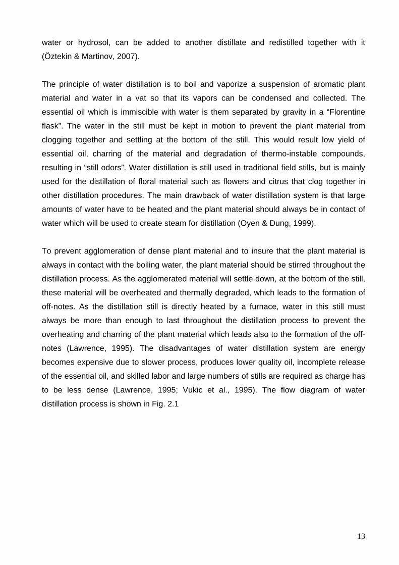
to be less dense (Lawrence, 1995; Vukic et al., 1995). The flow diagram of water
distillation process is shown in Fig. 2.1
14
WaterCharging
distillation stillPlant material
Distillation
Condenser Essential oil mixture carried by steam
Essential oil realize
Oil separator(Florentine vessels)
Essential oil
DistillateCondensate (water
& oil mixture)
Figure 2.1 Flow diagram of water distillation process (Source: Adapted from Lawrence, 1995; Öztekin & Martinov, 2007)
2.2.2.2 Water and steam distillation Water and steam distillation (also named wet steam distillation) is a method that has
characteristics of both water distillation and steam distillation. With this method, a metal
grid is placed in the still above the level of water and the plant material is thus avoided. As
only the water is heated, the risk of charring and the formation of “still odors” is reduced
but the hot walls of the still may cause some damage. Water and steam distillation are
used for many kinds of plant material, e.g., lavender, thyme, and peppermint (Oyen &
Dung, 1999).
The design of the equipment used is generally very similar to that used in water distillation
(Lawrence, 1995). The wet steam can be supplied from the boiling water below the
perforated grid at the bottom of the distillation still to provide a uniform steam passage
(Vukic et al., 1995). Otherwise, the steam will pass through dominant channels and will be
in contact with just some parts of the material. Even if the plant material can not be in
direct contact with the fire source beneath the still, as the walls of the stills are good
conductors of heat, unwanted still notes can also be obtained by over heating the plant
material. The wet steam can make the lower plant material resting on the grid quite wet,
and slow down the distillation process. It provides time and fuel economy as compared
with water distillation system. Higher yields of essential oils with minimum chemical
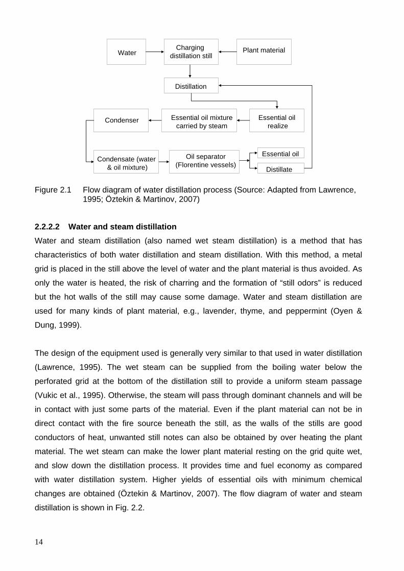
changes are obtained (Öztekin & Martinov, 2007). The flow diagram of water and steam
distillation is shown in Fig. 2.2.
15
Wet steam -from boiling water below the perforated grid or- from a separate boiler
Charging distillation still(Plant material over the
perforated grid)Distillation
Condenser Essential oil mixture carried by steam
Essential oil realize
Condensate(water & oil mixture)
Oil separator(Florentine vessels)
Essential oil
Distillate
Figure 2.2 Flow diagram of water and steam distillation process (Source: Adapted from Lawrence, 1995; Öztekin & Martinov, 2007)
2.2.2.3 Direct steam distillation In steam distillation (sometimes called “dry steam” distillation), a separate steam generator
is attached to the still. As in steam and water distillation, plant material is placed on a grid
in the distillation vat, but no water is added. Steam produced in the generator is forced
through the material to be distilled. High pressure steam is often used, e.g., steam of 5-10
bars pressure at 150-200 °C. The duration of the distillation process depends on the steam
temperature and the ease with which the essential oil can be removed from the plant
material. Plants in which oil is stored in hair glands can be distillated very easily; those in
which oil is stored in or below the epidermis require more intensive distillation. The main
advantage of steam distillation is that the amount of steam used and its temperature can
be readily controlled. As the vat walls do not become hotter than the temperature of the
steam, the risk of charring is minimal. Steam distillation is used for most of the essential
oils, except those from delicate flowers. The only precaution necessary when distilling
leafy material it is ensured that it is cut not too fine, since this may cause `channeling`
resulting in poor distillation yields. Channeling occurs when the plant material becomes too
compact. The steam then forces its way through via a few large channels, instead of
moving through the entire mass of plant material. Steam distillation is sometimes
conducted under reduced pressure, to lower the distillation temperature (Lawrence, 1995).
Steam distillation is the most common method of extracting essential oils on a commercial
scale. Approximately 80 to 90 percent of the essential oils are produced in this way. This
method is used for the fresh plant material that has high boiling point like seeds, roots and
woods. It is also used for fresh plant such as peppermint and spearmint, oil roses, and

16
chamomile. This type of distillation plant is similar to other types of distillation plants. The
only difference is that there is no water inside the still body during distillation. After the
plant material is loaded into the perforated grid, or in a basket or cartridge in side the still
body, the saturated or sometimes, overheated, pressurized dry steam that is generated in
a separate boiler or a steam generator is injected below the plant material as the steam
will flow in the direction of less resistance, the plant material should be uniformly
distributed in the still body. The essential oil of the plant material is separated by the
process of diffusion while steam passes through the plant material. The steam with a
certain contents of essential oil vapors moves through the condenser, usually cooled by
running fresh water, where the mixture is condensed. The mixture of condensed water and
essential oil is then collected and separated by decantation in Florentine vessel (Öztekin &
Martinov, 2007). The process of steam distillation is more suitable for commercial scale
operations. However, steam distillation has several advantages over the previously
described variants (Lawrence, 1995; FAO, 1992). It is more energy efficient, cost effective
and is the cheapest method of essential oils extraction. It provides better control of the
distillation rate. Quality of essential oils produced by this type of distillation units is more
consistent and repeatable. There is the possibility of changing working pressure that
enables the use of low pressure for high volatile oils and high pressures for low volatiles
ones. The rapid distillation is less likely to damage those oils containing reactive
compounds like esters. The obstacle for wider use of this type of distillation plant in
developing countries and its biggest disadvantage is the high capital expenditure for the
equipment.
Many of the demands of the process of steam distillation are often contradictory.
According to the existing knowledge the most important demands are to obtain all, or most
of the available essential oil from the raw material. To economically justify the process,
approximately 85 % of the essential oil in the plant must be obtained. The “dominant
channels” can be formed in the still during water and steam, and steam distillation
processes. This happens because the plant material gets denser by absorbing water and
fresh steam is now not able to move it, and pores in the randomly placed material in the
beginning get larger. In this way, only some part of the material is in touch with the steam
and obtaining essential oil is far from complete. This can be prevented by using mixers
such as auger inside the still body or chopping of the plant material before processing. The
risk of losing considerable amount of essential oil exists while chopping the plant material.
17
As the most efficient of all distillation processes, steam distillation is a very wasteful
process. It is always necessary to evaporate relatively high amounts of water to obtain a
small quantity of essential oil. Water is never saturated with essential oils vapors. On the
other hand, cooling water consumption is high. Cooling water temperature is usually 20 °C
at the input and is about 70 °C at the exit from the condenser. The flow rate of this water
is, for example, for processing of 300 kg of fresh plant material, up to 2000 kg per hour.
The problem is not just finding the enough rich sources, but affording the price and also
the possible micro pollution with water at that temperature. Further more, water from the
commercial pipe lines, for instance, has to be de-mineralized, prepared for the use in
steam generators and for some spiral type condensers (Dachler & Pelzman, 1989). For
the improvement of steam distillation system, the techniques like mobile distillation units,
turbo distillation, hydro diffusion, continuous steam distillation systems are used
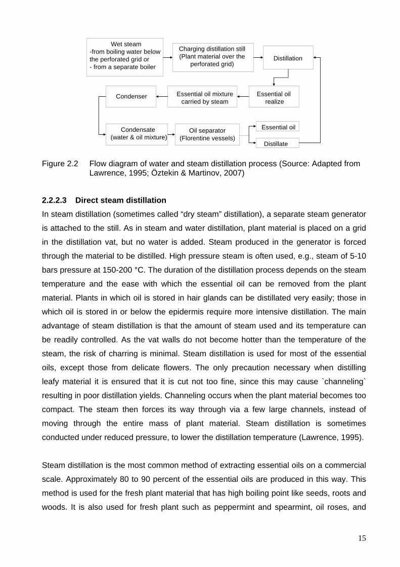
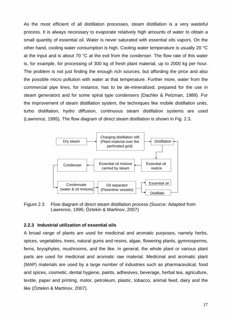
(Lawrence, 1995). The flow diagram of direct steam distillation is shown in Fig. 2.3.
Dry steamCharging distillation still(Plant material over the
perforated grid)Distillation
Condenser Essential oil mixture carried by steam
Essential oil realize
Condensate(water & oil mixture)
Oil separator(Florentine vessels)
Essential oil
Distillate
Figure 2.3 Flow diagram of direct steam distillation process (Source: Adapted from Lawrence, 1995; Öztekin & Martinov, 2007)
2.2.3 Industrial utilization of essential oils A broad range of plants are used for medicinal and aromatic purposes, namely herbs,
spices, vegetables, trees, natural gums and resins, algae, flowering plants, gymnosperms,
ferns, bryophytes, mushrooms, and the like. In general, the whole plant or various plant
parts are used for medicinal and aromatic raw material. Medicinal and aromatic plant
(MAP) materials are used by a large number of industries such as pharmaceutical, food
and spices, cosmetic, dental hygiene, paints, adhesives, beverage, herbal tea, agriculture,
textile, paper and printing, motor, petroleum, plastic, tobacco, animal feed, dairy and the
like (Öztekin & Martinov, 2007).
18
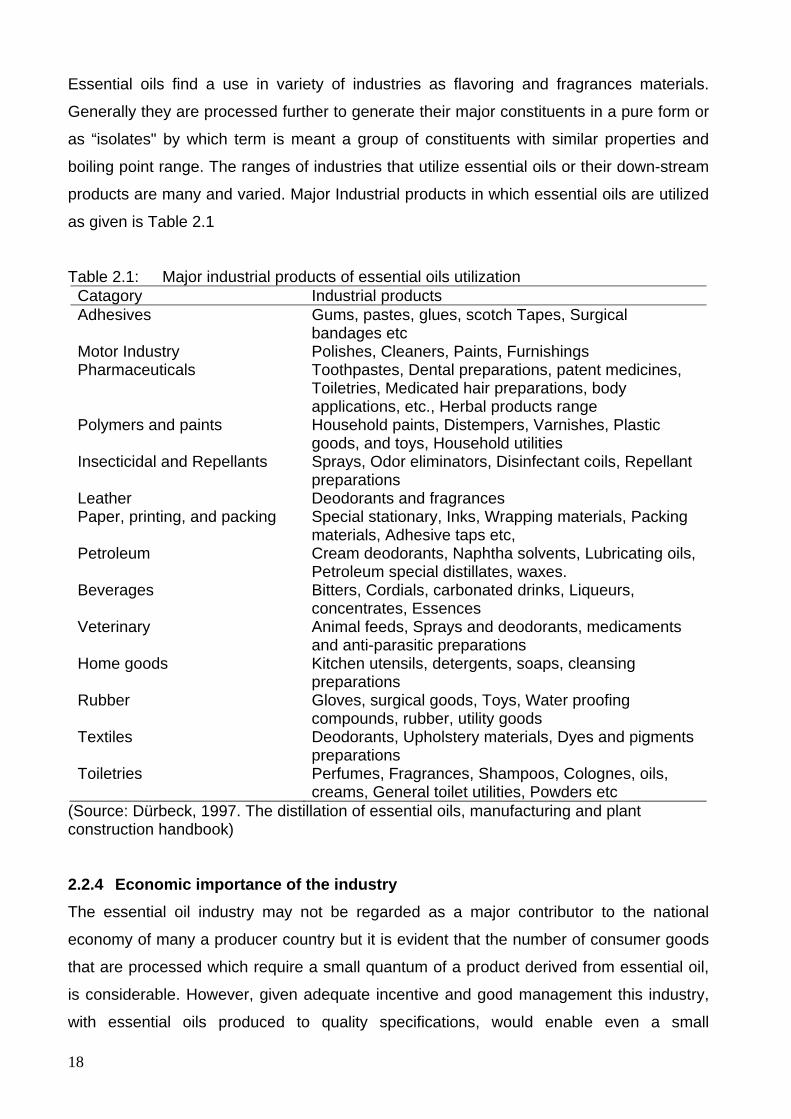
Essential oils find a use in variety of industries as flavoring and fragrances materials.
Generally they are processed further to generate their major constituents in a pure form or
as “isolates" by which term is meant a group of constituents with similar properties and
boiling point range. The ranges of industries that utilize essential oils or their down-stream
products are many and varied. Major Industrial products in which essential oils are utilized
as given is Table 2.1
Table 2.1: Major industrial products of essential oils utilization Catagory Industrial products Adhesives Gums, pastes, glues, scotch Tapes, Surgical
bandages etc Motor Industry Polishes, Cleaners, Paints, Furnishings Pharmaceuticals Toothpastes, Dental preparations, patent medicines,
Toiletries, Medicated hair preparations, body applications, etc., Herbal products range
Polymers and paints Household paints, Distempers, Varnishes, Plastic goods, and toys, Household utilities
Insecticidal and Repellants Sprays, Odor eliminators, Disinfectant coils, Repellant preparations
Leather Deodorants and fragrances Paper, printing, and packing Special stationary, Inks, Wrapping materials, Packing
materials, Adhesive taps etc, Petroleum Cream deodorants, Naphtha solvents, Lubricating oils,
Petroleum special distillates, waxes. Beverages Bitters, Cordials, carbonated drinks, Liqueurs,
concentrates, Essences Veterinary Animal feeds, Sprays and deodorants, medicaments
and anti-parasitic preparations Home goods Kitchen utensils, detergents, soaps, cleansing
preparations Rubber Gloves, surgical goods, Toys, Water proofing
compounds, rubber, utility goods Textiles Deodorants, Upholstery materials, Dyes and pigments
preparations Toiletries Perfumes, Fragrances, Shampoos, Colognes, oils,
creams, General toilet utilities, Powders etc (Source: Dürbeck, 1997. The distillation of essential oils, manufacturing and plant construction handbook) 2.2.4 Economic importance of the industry The essential oil industry may not be regarded as a major contributor to the national
economy of many a producer country but it is evident that the number of consumer goods
that are processed which require a small quantum of a product derived from essential oil,
is considerable. However, given adequate incentive and good management this industry,
with essential oils produced to quality specifications, would enable even a small
19
developing country to enhance its economic gains to a sustainable degree. The
technology involved is relatively simple and the variations possible enable innovations to
be made to accommodate a diverse range of conditions.
Agronomic expertise is available or can be produced. The industry itself is not always
capital intensive and the local design and fabrication of distillation equipment can cut
capital costs down to the absolute minimum. The labor intensive nature of the industry is
an advantage where labor availability is a factor. Price fluctuations so common to the
industry can also be circumvented if economic cultivation and harvesting techniques are
adopted, field distillations are carried out wherever feasible and quality ensured for the
products. The development of downstream processing of products such as isolates and
aroma chemicals from essential oils is an exercise that would also be profitable in the
correct circumstances, for even a developing country producer (Öztekin & Martinov, 2007).
2.2.5 Essential oils in local and regional health care markets The health systems are presently in a crisis. In the western world medicine is suffering
from the delusion of offering better and better individual services, most of them not actually
required or not adjusted to breaking diseases. Therefore, the medicines are no longer in
the position to fulfill its duty of health care. This is the present in the present scenario for
the application of aromatherapy for its use of local and regional traded essential oils. Due
to the emergency and emergence of the tropical diseases and the missing interests and
responsibilities of western pharmaceutical companies, the applications of genuine and
authentic essential oils for the primary health service of tropical countries offers local and
regional market incentives to essential oil producers out side the established markets
overseas. Figures of World Health Organization (WHO) show that, by western standards,
rather manageable diseases are the efficient killers on a global scale, or for that matter in
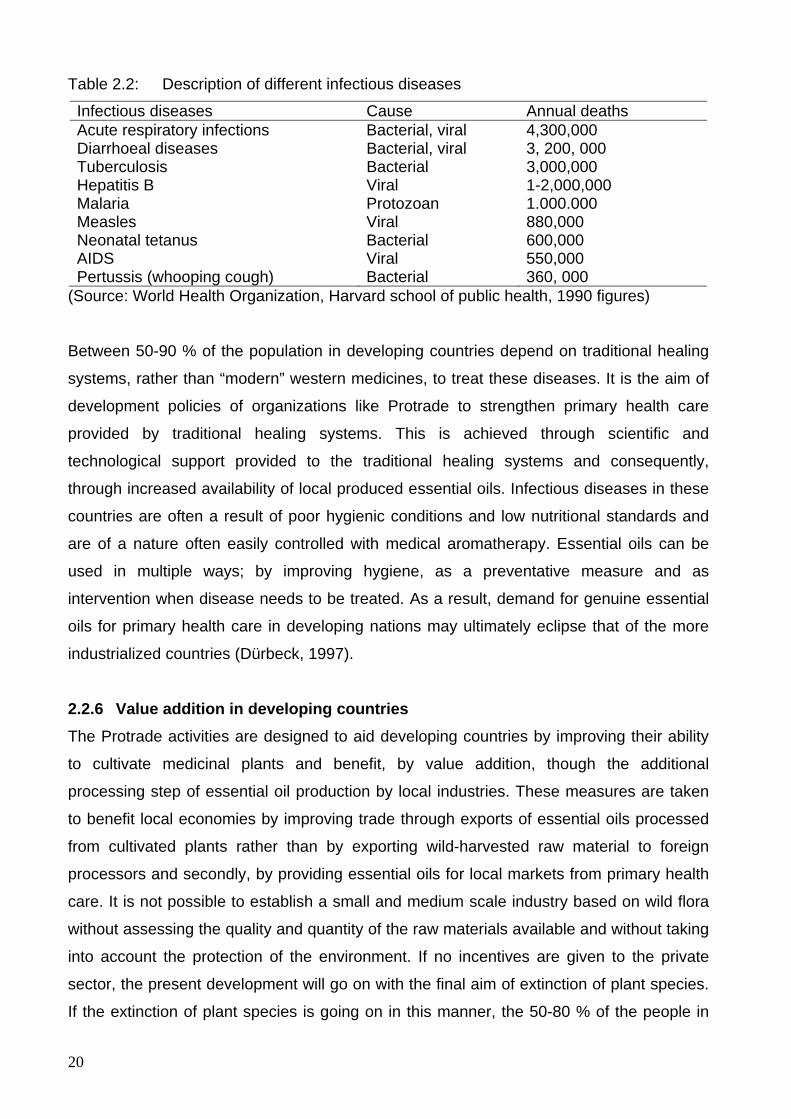
developing countries. For an appreciation of the potential of essential oil based health care
in developing nations, it is useful to take a look at the disease causing, in absolute
numbers, the most deaths globally.
20
Table 2.2: Description of different infectious diseases
Infectious diseases Cause Annual deaths Acute respiratory infections Bacterial, viral 4,300,000 Diarrhoeal diseases Bacterial, viral 3, 200, 000 Tuberculosis Bacterial 3,000,000 Hepatitis B Viral 1-2,000,000 Malaria Protozoan 1.000.000 Measles Viral 880,000 Neonatal tetanus Bacterial 600,000 AIDS Viral 550,000 Pertussis (whooping cough) Bacterial 360, 000
(Source: World Health Organization, Harvard school of public health, 1990 figures)
Between 50-90 % of the population in developing countries depend on traditional healing
systems, rather than “modern” western medicines, to treat these diseases. It is the aim of
development policies of organizations like Protrade to strengthen primary health care
provided by traditional healing systems. This is achieved through scientific and
technological support provided to the traditional healing systems and consequently,
through increased availability of local produced essential oils. Infectious diseases in these
countries are often a result of poor hygienic conditions and low nutritional standards and
are of a nature often easily controlled with medical aromatherapy. Essential oils can be
used in multiple ways; by improving hygiene, as a preventative measure and as
intervention when disease needs to be treated. As a result, demand for genuine essential
oils for primary health care in developing nations may ultimately eclipse that of the more
industrialized countries (Dürbeck, 1997).
2.2.6 Value addition in developing countries The Protrade activities are designed to aid developing countries by improving their ability
to cultivate medicinal plants and benefit, by value addition, though the additional
processing step of essential oil production by local industries. These measures are taken
to benefit local economies by improving trade through exports of essential oils processed
from cultivated plants rather than by exporting wild-harvested raw material to foreign
processors and secondly, by providing essential oils for local markets from primary health
care. It is not possible to establish a small and medium scale industry based on wild flora
without assessing the quality and quantity of the raw materials available and without taking
into account the protection of the environment. If no incentives are given to the private
sector, the present development will go on with the final aim of extinction of plant species.
If the extinction of plant species is going on in this manner, the 50-80 % of the people in
21
developing countries will suffer in their primary health care from two very dominant
developments. Firstly, modern medicines from the developing countries are not accessible
and secondly the medicinal plant species for their traditional preparations are
extinguished. One commercial approach to ameliorate the scientific developments of the
past is to make information and technology available to the decision makers of
government and private sector natural product industries in developing countries. In some
countries of medicinal plant industry is heavy under pressure from the scientists educated
in developed countries because they are afraid of commercial competition with traditional
healers and associated industries and on this new view of the ability of the essential oils to
be useful, holistic pharmaceuticals, novel approaches to support primary health care in
developing nations have been adopted. As a result of Protrade activities, genuine oils from
countries like Nepal, Madagascar, Tanzania and EI Salvador are beginning to gain a share
in the aromatherapy markets of industrialized nations, mainly France, Germany and US.
Essential oils from these countries, having found their way into aromatherapy commerce,
include: Nardostachys jatamansi, Palmarosa, Vetiver, Niaouli, Cinnamon and Cardamom.
It appears that essential oils manufacturers in developing nations are comfortable in
satisfying the requirements for genuine oils by the customers interested in medical
aromatherapy (Dürbeck, 1997).
2.2.7 Problems and prospective for aromatherapy in tropical counties Beside commercial plantations the industrial production of genuine and authentic essential
oils faces serious threats to a secured and sustainable supply of raw material due to
extinction of plant species from the wild caused by over consumption and endangered
habitats. Domestication, cultivation, forestry of essential oil plants in many developing
countries is limited due to the problems of technology transfer (pilot plants, distillation unit,
cold pressed essential oil), information transfer (market, IPR, EINECS), no standardization
(big quantity standard oils in demand) and local and regional marketing. The intellectual
property rights (IPR) and traditional knowledge of essential oil plants enclose the
enormous potential for biodiversity prospecting and for new regional and local markets in
Aromatherapy. The commercialization of new oils from tropical forests offers a treasure
house for a new horizon of applications out of The Hot Zone.
2.2.8 Different distillation plants for commercial applications As a sample, Dürbeck (1997) explained different distillation plants for commercial
applications. LT plant comprises a still mounted over a brickwork fireplace, a flue gas
22
stack, a condenser, a separator, and a lifting aid for the still cover. The fuel to be used for
firing the still is intended to be the spent plant material, but firewood is an acceptable
alternative. The type RT distillation plants are the improved version of the type LT and are
designed for continuous distillation on a commercial scale. The plant comprises two stills
heated by steam supplied from an external source, two shell and tube type condensers,
each with its own separator, and a load handling system. In most duplex plants, the two
stills are served by one condenser. The production capacity of RT plant is therefore much
higher than that of the type LT, and for this reason it is best suited at some central location
where it can serve a wide plantation area, therefore most likely to be in a town.
The type RT plant is offered in two versions, the type RTA and the type RTB. The only
difference between the two is that the type RTA uses a steam heating coil immersed in the
water in the still and therefore requires a still feed water system, where as the type RTB
uses a steam sparker at the bottom of the still which admits steam into it (steam injection
type). In RTA, the coil has been designed to provide the heating rate required to achieve
the rated distillation rate of the still when supplied with steam at 10 bars. The water in the
still boils, becomes steam at 100 °C and rises up through the charge of the plant material,
contacting it at this temperature. In RTB type distillation plants, plant material with high
boiling point oils, the higher temperature steam can be used by adjusting the supply of
pressure accordingly, for instance, steam at 3 bars would be at 141 °C. In most cases,
however the requirement would be for steam as close to 100 °C as is practical, that is,
steam at atmospheric pressure. The pressure reducing valve at the sparker inlet would
therefore be adjusted say, 0.25 bar. The condenser from the type RTB is therefore
contaminated and must be discarded, whereas that from the type RTA is recovered and
returned to the boiler. RTB is well suited for the distillation of high boiling point oils, and the
desired temperature can be obtained by setting the boiler operating pressure accordingly.
For most plant materials, however, the supply steam pressure RTB should be as close as
is practical possible to atmosphere. The heating coils of type RTA operates at 10 bars and
this must be in fabricated from seamless pipe to a high standard of workmanship.
Meanwhile a spare cartridge which has been loaded with plant material is picked up and
loaded in the still and the second distilling cycles commences.
The type BT distillation unit consists of a simple still made of two standard 200 liters oils
drums placed one above the other, a small shell and tube condenser, and a type LT
separator. It is fired by a gas burner using cooking gas in standard cylinders. In remote
23
locations, firewood can be used in which case, the still must be mounted outdoors and a
suitable brickwork fireplace with a steel grating provided. Provision has been made to
remove the upper section of the still. The cover can then be transferred to the lower
section and the still, in its reduced state, can be used for distilling from very small amounts
of plant materials. The plant can easily set up and dismantled. The separator and the
support legs assembly can be placed within the still body for transport. It requires no
foundation.
The type QT distillation plant is designed as a research still for low volume of distillation of
high value oils. Its condenser is of shell and tube type and is mounted integral with the still
to provide a single unit plant. The top of the cover is in the shape of an inverted cone
which enables any vapors that condense on its surface to run down and drip into the
condenser vapor inlet. Heating is by a steam coil supplied from an external source at a
supply pressure of 3 bars or alternately it can be electrically heated by an industrial type
heating element fitted in place of steam coil. The heat input is limited by the capacity of
heating device (be it steam or electric) and there is no need for low-water protection. The
plant is made of stainless steel through out, except for the condenser shell which is of mild
steel. This gives the plant a long service life and facilitates cleaning of its internals
(Dürbeck, 1997).
2.2.9 Guidelines during distillation In the case of stills, of the type LT, where the steam is generated in situ, the wetness of
the steam is fixed and the rate of flow is determined by the rate at which heat is applied to
the water containing reservoir at the base of the still itself. The time of completion the
distillation has to be determined by plotting the graph for total volume of oil condensed
versus time. The distillation is complete when the curve is flattens off indicating that almost
a hundred per cent of the oil has come over. Studies in order to determine optimum time of
distillation may be carried out using the pilot plant scale stills such as type BT. However
such results should be extrapolated to the field situation with care, as things could be
different. It is best to use the pilot scale results as a guide and to determine the operating
conditions in the field for use thereafter (Dürbeck, 1997).
In the RT-type stills, there is very facile control of the variables possible and hence the
steam related parameters could be determined with accuracy and applied with a degree of
consistency. When the batch size and the steam pressure is maintained constant and the
24
rate of injection of steam is varied with several conditions, a plot of the percentage
recovery of oil versus time will indicate the optimum steam injection rate. The optimum
distillation is again when near complete recovery of the oil is achieved, as recovery of the
final traces of the oil may not be economical in comparison to the expense of distilling for
several hours longer. The ultimate judgment on those parameters must be made by the
technologist after consideration of both the economic as well as scientific and
technological factors. The analysis of the oil in the prolong distillations must be compared
with that of a sample distilled where economical considerations have curtailed the time of
distillation and the analytical picture must warrant the economic trade off else the oil may
fall short of market stipulations.
The efficiency of steam heating is not much affected by the steam supply pressure. The
higher the pressure, the hotter the steam and this can be detrimental to the product
quality. The most convenient operating pressure is, of course, atmospheric. All the stills
presented here operate normally at atmospheric pressure, but it must be appreciated that
there will be a small back pressure on the still which is needed to push the distillate
through the condenser. This varies from 25 mm to 500 mm of water depending on the
condenser type and the operating conditions.
The types BT and LT stills contain a small amount of water at the bottom which is boiled
by lighting a fire under base of the still. These stills are intended for field use where
firewood or spent plant material is plentiful, and where electricity may not be available.
Also these stills are intended for local manufacture at low cost. Direct firing is the best
available option in these circumstances but it must be appreciated that the base of the still
will deteriorate from repeated firing and that there is an inherent “low water-overpressure
“danger potential. The steam contacting the plant material is at 100 °C which is acceptable
for most plant material. This temperature remain constant for the duration of the distillation
without any action from the operator, but the rate of distillation will depend on the rate of
firing and much depends on the skill and experience of the operator to achieve the exact
firing rate and to maintain throughout the distillation run (Dürbeck, 1997).
2.2.10 Distillation options The distillation options are often dictated by the nature of the raw material and the
equipment available. Bulky materials call for the use of field stills. They can be either the
LT-type with built-in fire places or the RT-type which use a satellite steam source.
25
Although the former is less costly, the latter affords better control of the distillation and, as
discussed earlier, is in the longer term more cost effective. These stills and their respective
features have been discussed before from the view point of their utility. The pre-
preparation of the raw material is an important consideration in the production of quality
essential oils. The pre-preparation varies from material to material due to differences in the
manner the essential oils containing cellular vessels are located within the plant (Dürbeck,
1997).
Distillation is a heat dependent separation and purification process of a liquid mixture
based on the vapor pressure difference. It can be defined as a method of extracting an
essential oil from the plant material by evaporating and subsequent condensation of the
liquid. Similarly, the cost of production depends highly on the scale of the production small,
medium or industrial scale production, raw materials, processing equipment, energy, and
labor requirement (Öztekin & Martinov, 2007).
For the distillation of moderately volatile oils under atmospheric pressure, the rate of steam
flow is a greater factor in the speed of oil recovery than the steam’s density. The volume of
steam generation is then more important than the operating pressure (Denny, 1991).
2.3 Solar energy utilization 2.3.1 Solar energy application in medium temperature range A large number of industrial processes demand thermal energy in the temperature range
of 80–240 °C (Proctor & Morse, 1977; Kalogirou, 2003). Solar thermal flat plate collectors
are not suitable for very high temperature applications. For high temperature applications,
different solar concentrators may be employed. A number of solar industrial process heat
systems are installed and operated on experimental basis have reported the status of the
development of medium temperature solar collectors for industrial applications. In this
temperature range, solar thermal systems have a great scope of application (ESTIF, 2004;
Weiss & Rommel, 2005). However, the challenge lies in the integration of a periodic,
dilute and variable solar input into a wide variety of industrial processes. Issues in the
integration are selection of collectors, working fluid and sizing of components. Application
specific configurations are required to be adopted and designed. The specific configuration
consists of concentrating collectors, pressurized hot water storage and a load heat
exchanger. The solar systems are in a developmental stage for medium temperature
industrial applications and yet to achieve a full commercialization (ESTIF, 2004).

26
Application-specific configurations are required to be adopted and designed. Design
issues in solar industrial process heat systems involve the selection of appropriate type of
collector and the working fluid, and optimal system sizing i.e., to determine the appropriate
collector area, required storage volume and the size of the heat exchanger.
Kulkarni et al. (2008) described that as far as selection of appropriate type of collector is
concerned, thermal efficiency at the desired temperature, energy yield, cost and space
occupied are the deciding factors. Water, as a working fluid, is the preferred choice for low
temperature applications on the basis of thermal capacity, availability, storage
convenience and cost. However, for process heat applications above 100 °C, water must
be pressurized. Storage cost rises sharply with increasing system pressure. Commercially
available mineral oils are also used for medium temperature (above 100 °C) applications.
However, applicability of these oils is restricted due to cost, tendency of cracking and
oxidation.
An important design issue in solar thermal system for industrial applications is the optimal
sizing of the system i.e., appropriate sizing of the collectors, storage and heat exchanger.
Different guidelines and methodologies are available to design solar thermal systems
operating up to 100 °C (Klein et al., 1976; Klein & Beckman, 1979; Pareira et al., 1984;
Abdel-Dayem & Mohamad, 2001; Kalogirou, 2004). For systems operating above 100 °C,
detailed simulation programs such as TRNSYS and SOLIPH have been applied (Kutscher
et al., 1982). However, there is a scope for developing general design guidelines for solar
industrial process heat systems for medium temperature applications (Clark, 1982; Eskin,
2000; Weiss, 2003).
Goswami (1999) described that for temperatures of up to 100 °C required for many
process heat applications; forced circulation water-heating systems can be used requiring
a large collector area, storage and pumps etc. For higher temperatures, evacuated tube
collectors or concentrating collectors must be used.
Proper design of solar water heating system is important to assure maximum benefit to the
user, especially for a large system. Designing a solar hot water system involves
appropriate sizing of different components based on predicted solar insolation and hot
water demand (Kulkarni et al., 2007).

27
Beyond the low temperature applications there are several fields of application of solar
thermal energy at a medium and medium-high temperature level (80-240 °C). The most
important of them are: heat production for industrial processes, solar cooling and air
conditioning, solar drying and sea water de-salination. The industrial-heat demand
contributes about 15 % of overall demand of final energy requirements in the southern
European countries. The present energy demand in the EU is estimated to be 300
TWh/year (Kalogirou, 2003).
Norton (1999) presented the most common applications of industrial process heat. In
particular, the history of solar industrial and agricultural processes applications was
presented and practical examples were described. Around 105 GWth correspond to 150 million square meters of solar thermal collectors were
installed by the year 2004 worldwide. Until now, the wide spread use of solar thermal
plants has focused almost exclusively on swimming pools, domestic hot water preparation
and space heating in the residential sector. The use of solar energy in commercial and
industrial companies is currently insignificant compared to the sectors mentioned above.
Most solar applications for industrial processes have been on a relatively small scale and
are mostly experimentally in nature. The major share of energy, which is needed in
commercial and industrial companies for production, processes and for heating production
halls, is below 250 °C. The low temperature level (80 °C) complies with the temperature
level, which can easily be reached with solar thermal collectors already on the markets.
For applications where temperatures up to 250 °C are needed, the experiences are rather
limited and also suitable collectors are missing. Therefore, for these applications, the
development of high performance solar collectors and system components are needed.
One of the objectives of Task 33/IV is to develop, improve and optimize solar thermal
collectors for the temperature level from 80 °C to 250 °C (medium temperature collectors).
The collectors investigated in cooperation with the industry are double glazed flat plate
collectors with anti-reflection coated glazing, stationary CPC collectors, MAReCos
(maximum reflector collectors), Parabola trough collectors as well as linear parabola
Fresnel collectors. This report gives an overview and some background information about
the present state of the art of the medium temperature collector developments carried out
in the frame work of the EIA Task 33/IV on Solar Heat for Industrial processes (Weiss,
2005).
28
Various high-temperature solar thermal power systems have been suggested and
developed, such as parabolic trough, compact linear Fresnel reflector in single axis
tracking technology area and paraboloidal dishes, single tower-central generation,
distributed tower systems in two axis tracking technology area (Mills, 2004). But owing to
the complex technologies and high costs, the high-temperature, solar thermal systems are
still non-competitive, especially in developing countries (Wang et al, 2010).
2.3.2 Solar energy for industrial process heat demand Most of the process heat is used in food and textile industries for such diverse applications
as drying, cooking, cleaning, extraction and many others. Favorable conditions exist in
food industry, because food treatments are storage and processes with high energy
consumption and high running time. Solar thermal energy can be used for low-pressure
steam generation at 100-110 °C and for refrigeration which can be accomplished with
absorption cooling.
Dairies are very interesting applications for solar energy, because they often work seven
days a week, thus fully utilize the solar system compared to other industries, which allow
the system to be idle for 2 days per week. In the milk industry, thermal energy is used for
pasteurization (60–85 °C) and for sterilization (130–150 °C) processes. Drying of milk
powder, due to the high constant energy demand, is another important consumer. In the
production, milk and whey are spray-dried in huge towers with air, which is heated from
120 °C to 180 °C. The drying process can have a running time up to about 8000 h per
annum (Benz et al., 1998). In food preservation industries, several processes were
identified, where solar thermal energy could be used: scalding of vegetables, sterilization
(vegetables, fish and meat) with hot water or direct steam, scalding, cleaning and pre-
cooking of fish, sealing and cleaning of cans, cooking. In addition, cold demand can be
covered by solar absorption cooling and refrigeration. In the textile industry, energy is
mainly consumed for heating of liquid baths close to 100 °C for washing, bleaching and
dyeing. Drying processes usually use hot air or gases from 140 to 220 °C (Kalogirou,
2003). It is concluded from the results that it is more advantageous to apply solar energy
to higher temperature processes than to lower temperature ones as the saving incurred
are much higher. High technology collector like PTC cannot be used effectively for low
temperature applications (Kalogirou, 2003). It is also concluded that as the fuel price
increases, the more expensive collectors become viable and give much higher LCDs (Life
cycle savings) that flat-plate collector. The solar contribution drops at higher operating

29
temperatures and vice versa. This is because at higher load temperature more energy
from the auxiliary is required to cover the load. At low temperature, the best contribution is
from FPC whereas at higher temperature PTCs give the best contribution (Kalogirou,
2003).
Many important developments have occurred in solar concentrating systems for diverse
applications in the last decades. In particular, an important research effort has been
directed towards power generation applications, chemical systems, and process heat
(Estrada, 2007). High temperature heat production for electricity generation often requires
direct absorption of solar energy. To obtain direct absorption of solar energy, a parabolic
dish with receiver configuration is often used. A focal receiver absorbs the concentrated
solar radiation and transforms it into thermal energy to be used in a subsequent process.
The essential feature of a receiver is to absorb the maximum amount of reflected solar
energy and transfer it to the working fluid as heat, with minimum losses. Generally, a
conventional receiver is used to accomplish this purpose (Kumar, 2007). These parabolic
dishes with receiver configuration are often used for cooking applications and are termed
as solar cookers.
2.3.3 Evaluation of solar cookers The performance of solar cookers is evaluated by considering the controlled and
uncontrolled variables. The uncontrolled variables are wind, ambient temperature, pot
content temperature, insolation and solar altitude and azimuth. While controlled variable
includes loading, tracking and temperature sensing. Solar cooker tests should be
conducted when wind is less than 1.0 m/s at the elevation of the cooker being tested. If the
wind is over 2.5 m/s for more than 10 minutes, the test data should be discarded. The
reason is that the heat loss is strongly influenced by wind velocity. Wind velocities less
than 1.0 m/s help to maintain a heat loss coefficient close to the natural convection loss
coefficient. If wind shelter is required, it must be designed so as to not interfere with
incoming total radiation. Solar cooker tests should be conducted when ambient
temperatures are between 20 and 35 °C. The ambient temperature extremes experienced
in one location may be difficult to replicate at another location. Cooking power is influenced
by temperature difference. Available solar energy is to be measured in the plane
perpendicular to direct beam radiation (the maximum reading) using a radiation
Pyranometer. Variation in measured insolation greater than 100 W m-2 during a 10 minutes
interval or readings below 450 W m-2 or above 1100 W m-2 during the test render the test
30
invalid. The reason is that by maintaining moderate fluctuations in insolation levels
reduces the variability caused by thermal inertia effects. It is expected that most locations
will meet these criteria. If not, exceptions need to be specially noted. It is also strongly
recommended that tests be conducted between 10:00 and 14:00 solar time. Because the
solar zenith angle is somewhat constant at midday, and the difference between insolation
measured in the plane of the cooker aperture and the plane perpendicular to direct beam
radiation will vary least. Exceptions necessitated by solar variability (presence of clouds) or
ambient temperature (midday is too hot) must be specially noted. Parabolic-type units may
require more frequent adjustment to keep the solar image focused on the pot or absorber.
Thermocouples are recommended for their low cost, accuracy and rapid response.
Thermocouple junctions should be immersed in the water in the pots and secured 10 mm
above the pot bottom. The average water temperature (°C) of all the pots in one cooker is
to be recorded every 10 minutes, to one tenth of a degree if possible. Solar insolation (W
m-2) and ambient temperature are recorded at least as frequently (Funk, 2000).
2.3.4 Use of high reflectivity material for the reflectors Until a few years ago highly reflective aluminium sheet materials were predominantly used
as reflectors for lamps in office and industrial buildings. Because of their mechanical
properties and low cost compared to silvered glass mirrors, aluminized reflectors are
finding applicability to high temperature solar concentrating technologies. Furthermore
high reflectance aluminized sheet is already being successfully applied in low
concentrating technologies like compound parabolic concentrator (CPC) troughs and day
lightening. Of the material investigated, highly secular aluminium has an excellent chance
to meet the requirements for medium concentrating technologies like parabolic troughs.
For applications in humid climates, an additional polymer coating is necessary for
durability. Standard anodized materials show satisfactory hemispherical reflectance
properties after outdoor and accelerated exposure. Because of their manufacturing
flexibility and their low costs, mirrors based on anodized or coated sheet aluminium are a
promising alternative as primary or secondary concentrators in a number of solar energy
applications. They offer solar weighted reflectances of 88-91 %, good mechanical
properties and are easy to recycle (Fend, 2000).
2.3.5 Solar concentrators Solar thermal power plants generally concentrate the direct beam radiation, incidentally
rejecting a majority of diffuse radiations. Concentration by a factor C increases the incident
31
flux density at the solar receiver to the extent that radiation and convection losses are
acceptable even at elevated receiver temperatures. Even photovoltaic power systems may
use concentration, but here the objective is to reduce the required area of expensive
photovoltaic element by a factor of C. In any case, there are several points which must be
made about the optical systems employed so the design elements involved can be
appreciated.
• All the basic laws of optics apply without modification.
• The objectives are commonly different to concentrate energy cheaply rather than to
form a precise image, consequently different approximations are valid resulting in
sometimes surprising configurations.
• Collectors must be very large (compared to a camera lens) in order to intercept
significant power of order 2 m2 per thermal kilowatts or 2 km2 per thermal giga watt
(Winter et al., 1991).
Since 1990, solar community kitchens of the Scheffler cooker type have been
manufactured and installed at different places in Gujrat, India. The technical concept of the
Scheffler cooker is very appropriate to local infrastructure. This is because the tools
needed for constructions as well as the handling device are simple. This is fundamental for
a local production and for the acceptance of the kitchen staff. Two major problems were
found in the field of technical production, a rather complex construction and the needed
precision demand a sound training and careful workers and the mechanism for the daily
tracking of the reflector is obviously the week point of the whole system. Here every effort
should be made to find a less temperamental design. Scheffler cookers have an excellent
energetic efficiency with an estimated energetic payback of about half a year. Scheffler
cookers are economically viable if they are used regularly (Sutter, 1996).
2.3.6 Solar distillation of water Solar energy represents a vast energy resource which is most available in many areas
where population density may be low and where conventional energy resources may be
expensive. Its use for operation of desalination processes for production of fresh water is
technologically feasible. The principles basic to solar distillation had been known for many
years before the first significant installation was made in Chile in 1872. Located at Las
Salinas in a desert area, this solar still was a glass-covered installation which covered a
32
ground area of 50,000 sq. ft. and produced a maximum of some 5000 gallons per day
(gpd) of distillate for watering mules (Anonymous, 1970).
The double glazed AR-collector from ESE is applied in a solar driven, energy self
sufficient, stand-alone system for sea water desalination. It produces about 100-150 liters
of distilled water per day. The system was installed in December 2004 on the test site of
ITC in Gran Canaria. The typical operating collector temperatures are between 50 and 95
°C. The system uses 3 modules with an aperture area of 2.325 m2 each. The distillation
unit is developed by Fraunhofer ISE. The distillation technology is based on the membrane
distillation process (Weiss & Rommel, 2005).
2.4 Auxiliary energy utilization in solar distillation system The degree of reliability desired of a solar process to meet a particular load can be
provided by a combination of properly sized collector and an auxiliary energy source. In
the most climates, auxiliary energy is needed to provide high reliability and avoid gross
over design of the solar system (Duffie & Beckman, 2006). In a solar process heat system,
interfacing of the collectors with the conventional energy supplies must be done in a way
compatible with the process (Kalogirou, 2003). Several experiments were carried out
during adverse climatic conditions using solar energy integrated with biomass energy.
During hybrid solar distillation experiments, the distillation still was filled with water to
produce steam by reflected beam radiations on the still bottom and the extra energy was
taken from the biomass boiler. The experiments were conducted with different plant
material like Melissa, Peppermint, Lavender etc. (Munir & Hensel, 2009).
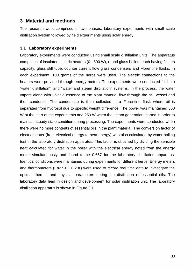
33
3 Material and methods The research work comprised of two phases, laboratory experiments with small scale
distillation system followed by field experiments using solar energy.
3.1 Laboratory experiments Laboratory experiments were conducted using small scale distillation units. The apparatus
comprises of insulated electric heaters (0 - 500 W), round glass boilers each having 2 liters
capacity, glass still tube, counter current flow glass condensers and Florentine flasks. In
each experiment, 100 grams of the herbs were used. The electric connections to the
heaters were provided through energy meters. The experiments were conducted for both
“water distillation”, and “water and steam distillation” systems. In the process, the water
vapors along with volatile essence of the plant material flow through the still vessel and
then condense. The condensate is then collected in a Florentine flask where oil is
separated from hydrosol due to specific weight difference. The power was maintained 500
W at the start of the experiments and 250 W when the steam generation started in order to
maintain steady state condition during processing. The experiments were conducted when
there were no more contents of essential oils in the plant material. The conversion factor of
electric heater (from electrical energy to heat energy) was also calculated by water boiling
test in the laboratory distillation apparatus. This factor is obtained by dividing the sensible
heat calculated for water in the boiler with the electrical energy noted from the energy
meter simultaneously and found to be 0.667 for the laboratory distillation apparatus.
Identical conditions were maintained during experiments for different herbs. Energy meters
and thermometers (Error < ± 0.2 K) were used to record real time data to investigate the
optimal thermal and physical parameters during the distillation of essential oils. The
laboratory data lead in design and development for solar distillation unit. The laboratory
distillation apparatus is shown in Figure 3.1.
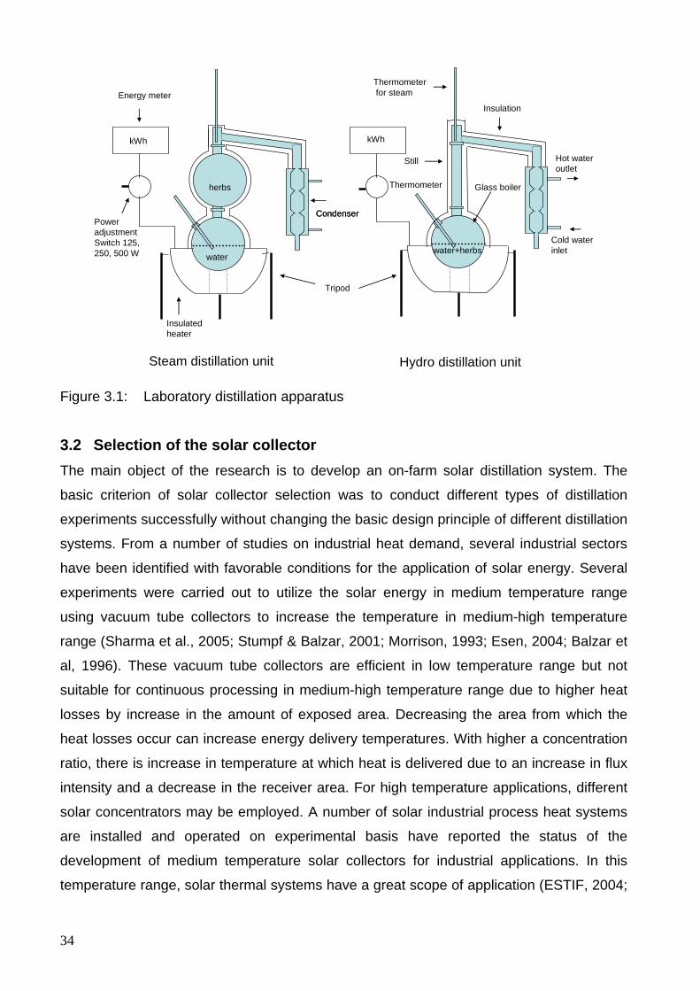
34
Tripod
Insulated heater
Hydro distillation unitSteam distillation unit
Condenser
Insulation
Thermometerfor steamEnergy meter
Still
Glass boiler
Power adjustment Switch 125, 250, 500 W
kWh
water
herbs
water+herbsCold water inlet
Hot water outlet
Condenser
Thermometer
kWh
Figure 3.1: Laboratory distillation apparatus
3.2 Selection of the solar collector The main object of the research is to develop an on-farm solar distillation system. The
basic criterion of solar collector selection was to conduct different types of distillation
experiments successfully without changing the basic design principle of different distillation
systems. From a number of studies on industrial heat demand, several industrial sectors
have been identified with favorable conditions for the application of solar energy. Several
experiments were carried out to utilize the solar energy in medium temperature range
using vacuum tube collectors to increase the temperature in medium-high temperature
range (Sharma et al., 2005; Stumpf & Balzar, 2001; Morrison, 1993; Esen, 2004; Balzar et
al, 1996). These vacuum tube collectors are efficient in low temperature range but not
suitable for continuous processing in medium-high temperature range due to higher heat
losses by increase in the amount of exposed area. Decreasing the area from which the
heat losses occur can increase energy delivery temperatures. With higher a concentration
ratio, there is increase in temperature at which heat is delivered due to an increase in flux
intensity and a decrease in the receiver area. For high temperature applications, different
solar concentrators may be employed. A number of solar industrial process heat systems
are installed and operated on experimental basis have reported the status of the
development of medium temperature solar collectors for industrial applications. In this
temperature range, solar thermal systems have a great scope of application (ESTIF, 2004;

35
Weiss & Rommel, 2005). Modern parabola trough concentrators and central receiver
towers are operated by high-tech computer programmed tracking system and are used
only in large-scale applications to justify the high investment costs and gross over design.
In conventional paraboloid concentrators, not only frequent tracking about two axes is
required but also receiver has to fix at the focal point as an integral part of the reflector.
Moreover, focus lies in the path of incident beam radiations. Despite of the high
temperature output, such types of concentrators are not suitable for distillation and cooking
purpose due to frequent changes of the focus position and inadequacy of handling
approach at the receiver. This limitation, however, is solved by the Scheffler fixed focus
concentrator which not only provides simple and precise automatic tracking but also a
fixed focus away from the path of incident beam radiations. For small scale applications in
agriculture, post harvest technology and food industry, this is a cheaper solution.
Moreover, this type of concentrator can be completely fabricated in an ordinary workshop.
In order to operate an on-farm distillery for the processing of different kinds of medicinal
and aromatic plants, Scheffler concentrator was selected because of fixed focus and can
be used for different types of distillation system and easy to fabricate. The present work
also describes the complete design details to construct a Scheffler fixed focus
concentrator which is one of the major components of the solar distillation system.
3.3 Development of Solar distillation system The main object of the research is to develop an on-farm solar distillation system to
process the fresh supply of different medicinal and aromatic plants with solar energy. The
distillation technology is relatively simple and adoptable in rural areas. Basically, a simple
distillation unit consists of four parts: furnace (heat source), distillation still, condenser, and
oil separator. Although the principle of distillation is the same, practical application of this
technique differs depending on the type and physical form of the plant material. Three
types of distillation are in practice. These are “water distillation” (distillation with water),
“water and steam distillation”, and “steam distillation” (distillation with steam). The yield,
composition, quality, and commercial value of the essential oils are generally affected by
the type and efficiency of the distillation unit, as well as the age of the harvested plant
material and the ecological conditions where the plant material is cultivated or wild
harvested (Öztekin & Martinov, 2007). The present study is focused to develop a solar
distillation system where all these three types of the distillation can be run successfully.
The system comprised of a paraboloidal type primary reflector (8 m2 surface area),
36
secondary reflector (0.343 m2), distillation still, condenser and Florentine flasks to separate
the essential oils from hydrosol.
3.3.1 Description of Scheffler reflector for solar distillation system The prototype of solar distillation for the processing of medicinal and aromatic plants was
designed and developed using an 8 m2 surface area of Scheffler fixed focus concentrator.
The complete construction of Scheffler fixed focus concentrator was carried out in the
Agricultural Engineering workshop, University of Kassel, Witzenhausen, Germany to
develop the solar distillation prototype. The solar system comprised of a primary reflector
having 8 m2 surface area and secondary reflector. The main components of the primary
reflector are elliptical reflector frame, a rotating support, tracking channel, reflector stand,
and daily and seasonal tracking devices. The primary reflector is designed by considering
the lateral part of a specific paraboloid. The semi-major axis and semi-minor axis of
elliptical reflector frame were taken as 1.88 and 1.37 m respectively. Seven crossbars
were designed and used in the elliptical frame to form the required section of the
paraboloid. These crossbars were equally distributed along minor axis with one crossbar
at the center and others were located at a distance of 0.48 m from the preceding on both
sides. These crossbars were checked with the help of a jig specially designed for the
profiles checking of the Scheffler reflector. The design and construction of the elliptical
reflector frame and the crossbar curves are detailed in section 4.2. Aluminium profiles
were fixed on the crossbars and aluminium sheets were pasted on aluminium profiles to
give the required shape of the lateral part of the paraboloid. The rotating support was
fabricated as an integral part of the primary reflector comprising of an axis of rotation
(constructed of a steel pipe), a tracking channel (channel bent in semi-circular form and
welded around the axis of rotation with supports). The reflector stand was grouted
vertically on the site with its foundation firmly bolted with the steel plates and reinforced by
welding. The solar distillation system was installed at solar campus, University of Kassel,
Witzenhausen, Germany (latitude, 51.3°). The journal bearings assembly was welded with
the reflector frame along the line parallel to the polar axis by setting it in north-south
direction and inclination angle (51.3°) with the horizontal. At the end, the axis of rotation
(steel pipe) of the reflector assembly was inserted into the journals bearings to complete
the reflector.
Photovoltaic (PV) tracking device was used to rotate the primary reflector by chain
sprocket mechanism for daily tracking. This PV tracking system composed of two PV
37
plates, a geared motor, and cables and was attached on the center bar of the primary
reflector to operate with solar energy. Daily tracking device rotates the reflector along an
axis parallel to the polar axis of earth with an angular velocity of one revolution per day to
counter balance the effect of earth rotation. The seasonal tracking device is made of
telescopic clamps mechanism and is rotated manually at half the angle of solar
declination. It also induces the desired shape of the reflector paraboloid in order to get the
fixed focus through out the year. The principle of operation for daily and seasonal tracking
is detailed in sections 4.2.6 and 4.2.7. In order to run the distillation experiments according
to the standards indicated in different literature (Dürbeck, 1997; Öztekin & Martinov, 2007;
Denny, 1991), a secondary reflector was constructed to further reflect the beam radiations
on the circular bottom of the distillation still. The secondary reflector comprised of seven
aluminium strips which are arranged in a circular form on a fixed bricks foundation to run
the distillation experiments throughout the year. The secondary reflector has provision to
accommodate 400 mm diameter and 120 mm lateral part of the distillation still inside the
secondary reflector.
3.3.2 Use of secondary reflector for water and steam distillation In order to fulfill the standards of distillation stills designed for “water” and “water and
steam” a secondary reflector has been used to further reflect the beam radiations onto the
bottom of distillation still as shown in Fig. 3.2.
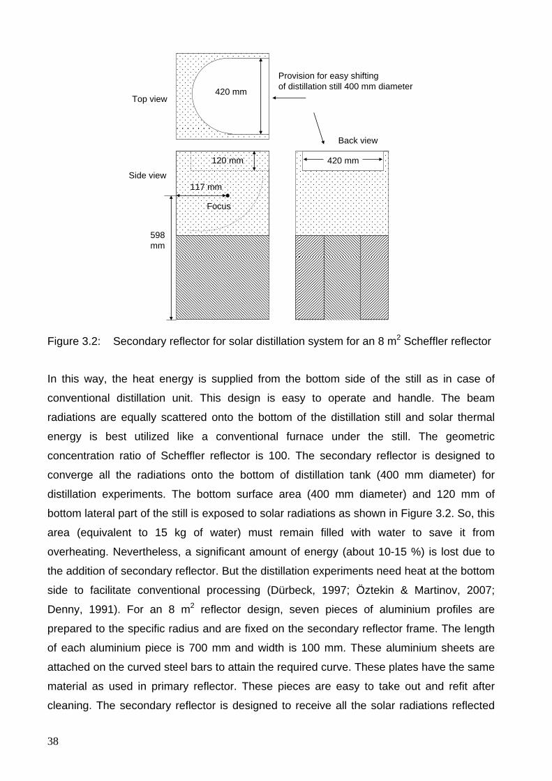
38
400 mmTop view
Back view
Side view
Provision for easy shifting of distillation still 400 mm diameter
598mm
117 mm
420 mm
420 mm
Focus
120 mm
Figure 3.2: Secondary reflector for solar distillation system for an 8 m2 Scheffler reflector
In this way, the heat energy is supplied from the bottom side of the still as in case of
conventional distillation unit. This design is easy to operate and handle. The beam
radiations are equally scattered onto the bottom of the distillation still and solar thermal
energy is best utilized like a conventional furnace under the still. The geometric
concentration ratio of Scheffler reflector is 100. The secondary reflector is designed to
converge all the radiations onto the bottom of distillation tank (400 mm diameter) for
distillation experiments. The bottom surface area (400 mm diameter) and 120 mm of
bottom lateral part of the still is exposed to solar radiations as shown in Figure 3.2. So, this
area (equivalent to 15 kg of water) must remain filled with water to save it from
overheating. Nevertheless, a significant amount of energy (about 10-15 %) is lost due to
the addition of secondary reflector. But the distillation experiments need heat at the bottom
side to facilitate conventional processing (Dürbeck, 1997; Öztekin & Martinov, 2007;
Denny, 1991). For an 8 m2 reflector design, seven pieces of aluminium profiles are
prepared to the specific radius and are fixed on the secondary reflector frame. The length
of each aluminium piece is 700 mm and width is 100 mm. These aluminium sheets are
attached on the curved steel bars to attain the required curve. These plates have the same
material as used in primary reflector. These pieces are easy to take out and refit after
cleaning. The secondary reflector is designed to receive all the solar radiations reflected
39
from the primary reflector and then further reflect it to the bottom of the distillation still. The
secondary reflector is placed on a fixed concrete foundation bed which facilitates the
accurate position of the secondary reflector. The focal point lies at a height of 598 mm
from the base level of the foundation and 117 mm away from the inner surface central
point as shown in Fig. 3.2.
Before starting experiment, the aluminium profiles of secondary reflector should be
washed with water by adding 2-3 drops of washing solution. These strips are placed in
some shady place for drying and then replaced. The primary reflector should also be
washed in the same way twice in a month to improve the reflectivity of the aluminium
profiles. The frequency of washing depends on the presence of dust particles on the site
etc.
3.3.3 Fabrication of the still for solar distillation system The still body is the container for the charge of plant material which is to be distilled. The
capacity of distillation still is variable and dependent on the scale of the envisaged
operation. The cylindrical still body that is mounted vertically has more practical usage
than any other and is suited to a variety of needs prevalent in the producer countries. The
judgment of the appropriate size is related to the quantity of the plant material available for
distillation per harvest, availability of water and steam, energy sources and availability,
labor availability, transport and storage facilities for the raw material and oil (Dürbeck,
1997). The still body is also equipped with a perforated grid near the bottom of the body
itself. The charge is loaded so as to rest on this grid while performing water and steam
distillation. In the experiments where water-cum-steam distillation method is used, the
compartment below the grid serves as the reservoir for the boiling which generates the
steam. In a cylindrical still, the space between the water and the herb supporting grid
should have a depth to one-fifth of the still’s diameter. This leaves room for an efficient
scheme of baffles (Denny, 1991). In the present model designed for water cum steam
distillation, the still body rests on secondary reflector which heats the bottom of the still
indirectly by secondary reflected beam radiations containing the reservoir of water. The
perforated grid comprises of two semi-circular pieces and is removable to conduct water
distillation experiments. Various protective coatings are available on mild steel but these
do not stand up to operation at 100 °C, in the long term, and when they eventually begins
to part from the parent surface, this actually accelerate corrosion (Dürbeck, 1997). The
40
distillation still was fabricated of a food grade stainless steel vessel having 1210 mm
column height, 400 mm diameter and 2 mm as shown in the Figure 1-A (Appendix A).
The diameter of distillation still is taken as 400 mm to reflect all the radiations on the
bottom of the distillation still. The still vessel is fabricated as pressure tight and all welds
relevant to this requirement are made continuous and of the required quality. Weld
surfaces are prepared in accordance with good welding standards. The still is also
provided with safety mountings and fittings like safety valve, pressure gauge, water level
indicator etc. The drain line connection was provided at the bottom to drain the water of
used charge. The still was pressure tested to check against any leakage by installing a
vertical pipe element to the vapor outlet connection plugging the drain line and filling with
water to the top of vertical pipe element. The top cover is of conical shape and is made of
2 mm stainless plate and its lateral part is 4 mm thick so that it may not distort during
welding and must seat flat on the rim packing to provide a pressure tight seal as shown in
the Fig. 2-A (Appendix A). Three I-bolts are used for quick opening and closing of the
conical top cover during distillation experiments. The clamps were accurately positioned
and those parts of it mounted on the cover are registered exactly with those on the still
body as shown in Fig. 3-A (Appendix A).
3.3.3.1 Thermal insulations Loss of heat from the still is accompanied by a corresponding condensation within the still,
which later re-boils. This could have detrimental effect on product quality (Dürbeck, 1997).
Thermal insulation is therefore an important requirement quite apart from energy usage
considerations. Rockwool was used to insulate the distillation still and the insulation was
held with a wire or strap binding. The galvanized sheet cladding was then placed in
position, the battens pushed in on the bolts, and their nuts tightened. The entire still body
was adequately insulated with 60 mm thickness rockwool insulation to minimize the losses
of heat. The galvanized sheet cladding (1 mm thickness) is then placed in position, the
battens pushed in on the bolts, and their nuts tightened. The insulation was held with a
wire or strap binding. The distillation still comprised of vertical shell (900 mm height) and
top cover. Upper 780 mm of the vertical shell of the distillation still was insulated while
bottom and 120 mm bottom lateral part was not insulated as this portion of the still
exposed to the solar radiations and painted black with solar mat.
41
3.3.4 Fabrication of condenser The main function of the condensing system is to convert the vapor mixture of the steam
and essential oil which emerges from the still body outlet, swiftly into liquid phase. This
function involves the removal of the heat from the vapor phase to render it into the liquid
phase and to bring the resultant mixture of aqueous and oil phases to near ambient
temperature, about 35-45 °C.
In general practice within the essential oil industry, there is variety of different types of
condensers in common use. The most two popular designs are known as the coil-in-water
type and shell-and tube type. In the developing country situations in the field, the coil type
is more prevalent. The reason is based both on economy as well as on grounds of ease of
fabrication in circumstances where good workshop facilities are not available.
The condenser is provided with steel coil, a cold water inlet connection and warm water
outlet connection and acts as a counter current flow heat exchanger. The whole coil is
immersed in static water tank. The upper part of the water is maintained boiling whilst the
lower part of the tank in which rest of the coil is immersed, completes the cooling process.
The complete condenser unit is also made of stainless steel material along with the vapor
outlet pipe from still to condenser. The shell and core of the condenser are fabricated for
water tight. The shell was leak tested by filling with water and core by immersing in water
and checking for air bubbles. The coil is a stainless steel tube bent on a tube bending
machine of the correct diameter to produce a coil of the specified diameter and pitch. The
diameter of coil is 10 mm and pitch is 25 mm. The diameter, height and wall thickness of
the shell are 250, 350 and 3 mm respectively as shown in Figure 4-A (Appendix A). The
coil unit is placed loose inside the shell. Cooling water inlet and outlet connections are
provided from the bottom and top sides of the condenser shell respectively for efficient
condensation of the steam inside the coil.
3.3.5 Florentine vessel or oil separator The condensate that emerges from steam distillation (that is the distillate), is a mixture of
essential oil and water. The essential oil may eventually settles as an upper layer (lighter
than water) or as a lower layer (heavier than water). Sometimes, it settles as both an
upper layer and lower layer due to the fact that lighter fractions which come over first form
a single upper layer while the heavier fractions agglomerate at the bottom as a lower layer.
The function of oil separator or Florentine vessel is to separate the oil from the water

42
phase and is designed to accommodate all of the situations above. The essential oils are
sparingly soluble in water and this is the property that makes it possible to affect the
separation from the aqueous phase. The Florentine vessels were designed to enable the
continuous removal of the water phase during distillation. In some cases, water-soluble oil
contents are economically significant and are recycled.
When the specific gravity of the oil is only marginally less than that of water, it is preferable
if the condensate flows into the separator at about 40-45 °C. This is because the specific
gravity (SG) of the oil decreases relatively more than water in increased temperature. The
greater the differential between respective specific gravities, the better the separation of
the two phases into layers. Where the specific gravity of the oil is marginally greater than
water, the distillate should run as cold as possible (Dürbeck, 1997). All three types of
Florentine flasks were used to separate the oil from the water depending upon the
experiments performed as shown in the Fig. 3.3. Different volumes of glass Florentines
were fabricated for the distillation system from the Glasswerk, University of Kassel,
Germany.
Figure 3.3: Separator types (Source: Dürbeck, 1997; Öztekin & Martinov, 2007)
3.4 Experimental set up and data acquisition The distillation unit has provision to operate for “water” and “water and steam” distillation.
A stainless steel pipe connects the top end of the distillation still to the steel condenser. In
order to record the power during distillation process, a barrel calorimeter is connected at
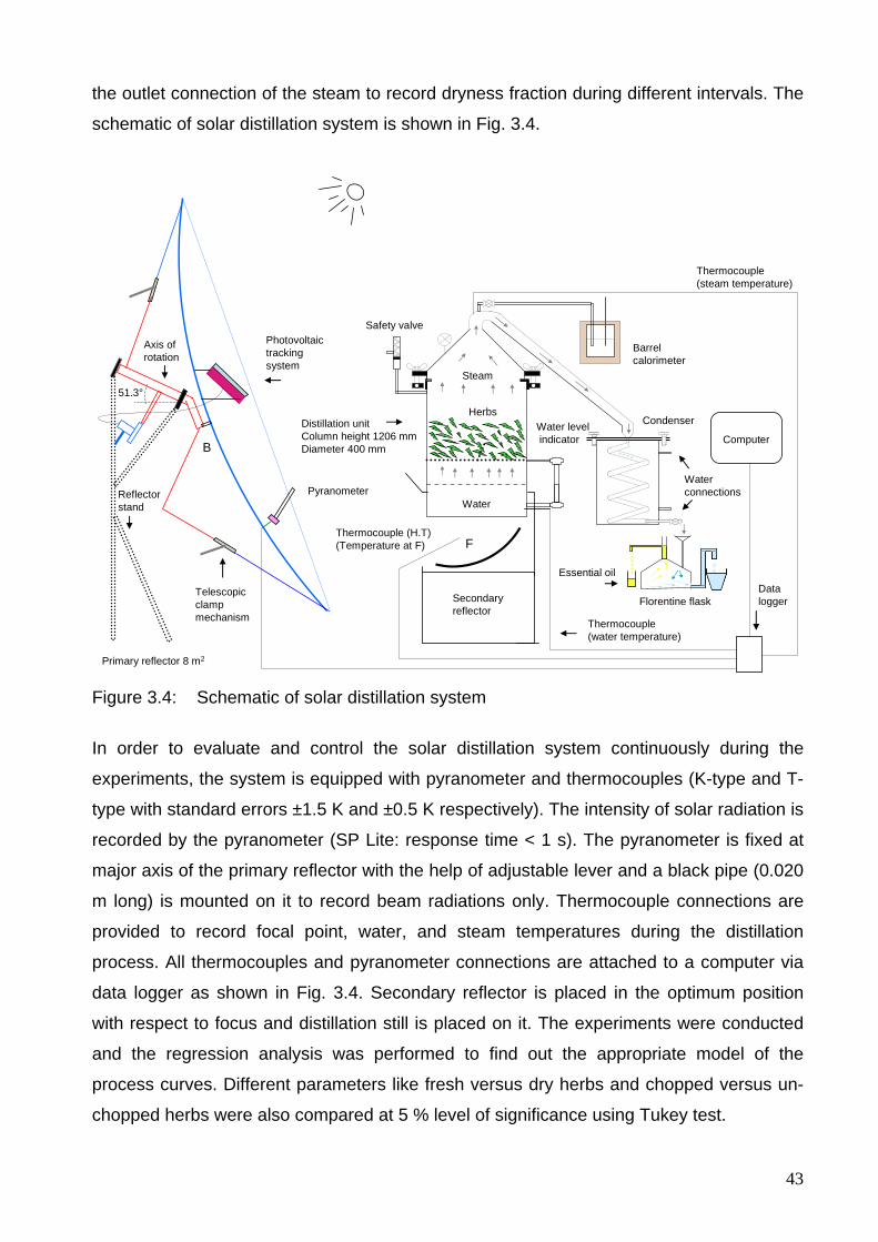
43
the outlet connection of the steam to record dryness fraction during different intervals. The
schematic of solar distillation system is shown in Fig. 3.4.
B
Telescopic clamp mechanism
F
Barrelcalorimeter
Safety valve
Water levelindicator
Condenser
Data logger
Thermocouple(steam temperature)
Thermocouple(water temperature)
Pyranometer
Photovoltaictracking system
Primary reflector 8 m2
Thermocouple (H.T)(Temperature at F)
Secondary reflector
Computer
Florentine flask
Distillation unitColumn height 1206 mmDiameter 400 mm
Herbs
Water
Steam51.3°
Reflectorstand
Water connections
Essential oil
Axis ofrotation
Figure 3.4: Schematic of solar distillation system
In order to evaluate and control the solar distillation system continuously during the
experiments, the system is equipped with pyranometer and thermocouples (K-type and T-
type with standard errors ±1.5 K and ±0.5 K respectively). The intensity of solar radiation is
recorded by the pyranometer (SP Lite: response time < 1 s). The pyranometer is fixed at
major axis of the primary reflector with the help of adjustable lever and a black pipe (0.020
m long) is mounted on it to record beam radiations only. Thermocouple connections are
provided to record focal point, water, and steam temperatures during the distillation
process. All thermocouples and pyranometer connections are attached to a computer via
data logger as shown in Fig. 3.4. Secondary reflector is placed in the optimum position
with respect to focus and distillation still is placed on it. The experiments were conducted
and the regression analysis was performed to find out the appropriate model of the
process curves. Different parameters like fresh versus dry herbs and chopped versus un-
chopped herbs were also compared at 5 % level of significance using Tukey test.
44
3.5 Operational procedure of the solar distillation system Operation commences with the opening of the still cover prior to loading it with the plant
material. The cover weighs about 5 kg and can be handled manually. The cover I-bolts are
loosened and swung out of the way. The still is charged with the plant material manually
and the cover replaced after checking the cover seal. For “water distillation”, the plant
material is placed in water and for “water & steam” and “steam distillation”, the plant
material is placed on the perforated grid. The water level in the distillation still is
maintained minimum 120 mm in the distillation still and this is equivalent to 15 liters (kg) of
water level under the available size of the distillation prototype. This water level
corresponds to the surface area of the still exposed to the solar radiations. While setting
the focus before starting an experiment, both the bolts of telescopic clamps are opened to
make the reflector free along seasonal tracking axis. The rotation along daily tracking axis
is always flexible due to the presence of clutch plate. In this way, the reflector can also be
rotated along both axis of tracking by holding telescopic clamps either from top side or
bottom side to set the focus accurately. The optimum focus is set by visualizing the
illuminated beam of solar radiation at the focus. If the focus is a little bit higher than the
designed focus point, then the top side of the reflector is tightened by fixing the downward
side and vice versa. The position of Pyranometer is adjusted to record the maximum beam
radiations. After the setting the reflector and position of Pyranometer, the data logger and
computer are taken in circuit to record the real time data. The data is automatically
recorded after 10 second intervals for the temperatures and beam radiations with the help
of thermocouples and pyranometer respectively.
All the running distillation parameters are observed during processing of plant materials.
Condenser flow rate is established in the condenser when the steam generation is started.
When the process is over, the reflector is rotated out of the focus to stop the distillation
process; the spent charge material is removed manually using a hay hook. The still is
drained out and washed. If there is much residual plant material remaining in the still, it
may be necessary to lift out the charge tray and hose the strainer clear of the material. The
still is filled with water again to set the level. The distillation cycle is now complete and the
still is ready for the next distillation cycle.
Two dangerous conditions can arise in the still during distilling; these are “over pressure”
and “low water”. Over pressure can cause the vessel to fail by stressing it beyond the
design limits. This is dangerous because the vessel contains vapor which is compressible
45
and will release energy if it fails. Low water is also dangerous as the vessel is being fired
and if there is no water; its base will become red hot and fail, with the same release of
energy. Overpressure can arise if there is some obstruction downstream of the vessel’s
vapor outlet. In the event of overpressure, the safety valve will blow off its steam. In order
to avoid low water level, ensure that the water level in the still should always be above the
safe minimum level of 180 mm for the existing design.
3.6 Mathematical modeling of solar distillation system The present study is conducted for a specific size of a solar distillation prototype. Two
mathematical models were developed in Matlab 7 and Microsoft Excel spreadsheet. First
model was developed to design the required size of Scheffler reflector which is one of the
major components of solar distillation system. Second model was developed to predict the
energy distribution and heat losses from different components of the solar distillation
system. These models can be used to optimize the existing solar distillation system as well
as to predict useful information for any required size and location of the solar distillation
system.
3.7 Biomass energy utilization in solar distillation system The degree of reliability desired of a solar process to meet a particular load can be
provided by a combination of properly sized collector and an auxiliary energy source. In
the most climates, auxiliary energy is needed to provide high reliability and avoid gross
over design of the solar system (Duffie & Beckman, 2006). For this purpose, a small scale
biomass boiler was developed as an auxiliary heat source to compensate for distillation
process during adverse climatic conditions at the site. The boiler is a vertical boiler type
and is designed only to hybrid the solar distillation system. The boiler comprises of a
vertical shell (360 mm diameter and 400 mm height), biomass furnace, and economizer
(360 mm diameter and 1 m height) and is equipped with all safety mountings like safety
valve, water level indicator, and blow off valve. The furnace has an arch with gradual
increasing area on top which opens in combustion chamber. A chimney passes though the
center of the boiler and economizer and then is exhausted to the atmosphere. Firewood,
bagasse, chaff husk or other spent biomass materials can be used as fuels in the furnace.
As a result of combustion, the heat energy is transferred to the bottom of the shell and the
burnt biomass is dropped down at the ash pit in the form of ash for continuous boiler
operation.
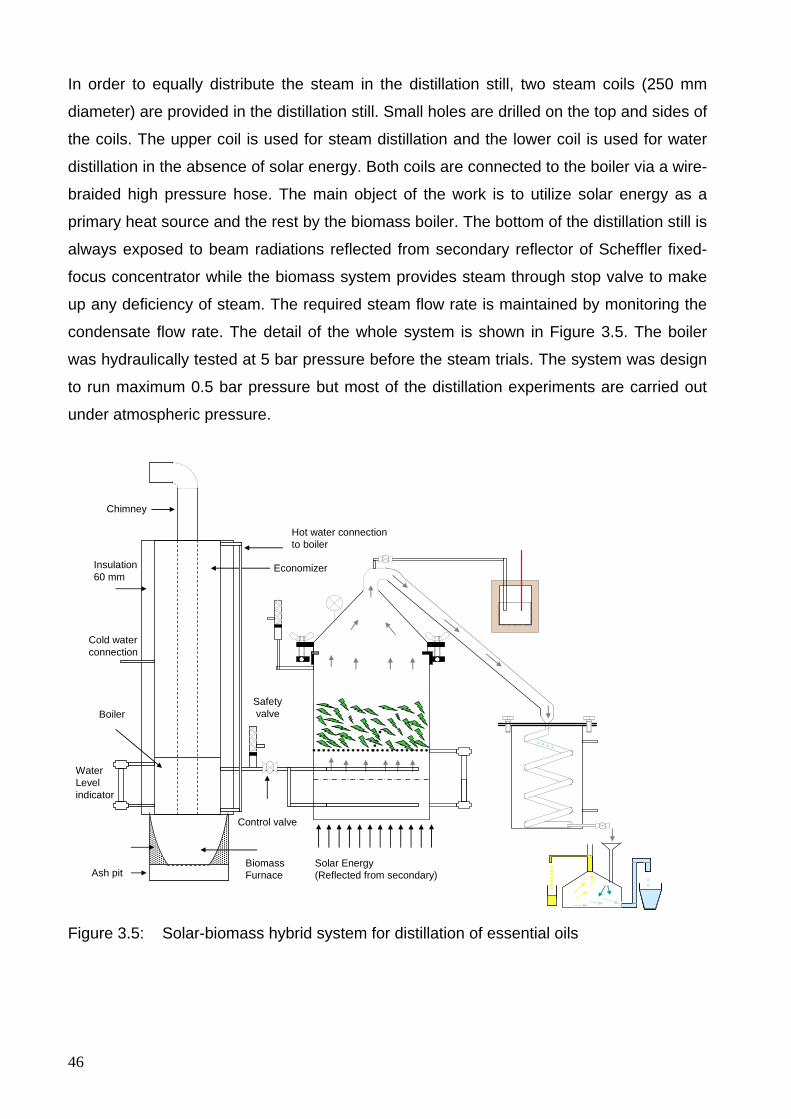
46
In order to equally distribute the steam in the distillation still, two steam coils (250 mm
diameter) are provided in the distillation still. Small holes are drilled on the top and sides of
the coils. The upper coil is used for steam distillation and the lower coil is used for water
distillation in the absence of solar energy. Both coils are connected to the boiler via a wire-
braided high pressure hose. The main object of the work is to utilize solar energy as a
primary heat source and the rest by the biomass boiler. The bottom of the distillation still is
always exposed to beam radiations reflected from secondary reflector of Scheffler fixed-
focus concentrator while the biomass system provides steam through stop valve to make
up any deficiency of steam. The required steam flow rate is maintained by monitoring the
condensate flow rate. The detail of the whole system is shown in Figure 3.5. The boiler
was hydraulically tested at 5 bar pressure before the steam trials. The system was design
to run maximum 0.5 bar pressure but most of the distillation experiments are carried out
under atmospheric pressure.
WaterLevelindicator
Insulation60 mm
Safetyvalve
Control valve
Economizer
Chimney
BiomassFurnaceAsh pit
Boiler
Solar Energy(Reflected from secondary)
Hot water connection to boiler
Cold waterconnection
Figure 3.5: Solar-biomass hybrid system for distillation of essential oils
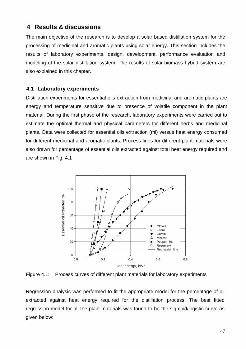
47
4 Results & discussions The main objective of the research is to develop a solar based distillation system for the
processing of medicinal and aromatic plants using solar energy. This section includes the
results of laboratory experiments, design, development, performance evaluation and
modeling of the solar distillation system. The results of solar-biomass hybrid system are
also explained in this chapter.
4.1 Laboratory experiments Distillation experiments for essential oils extraction from medicinal and aromatic plants are
energy and temperature sensitive due to presence of volatile component in the plant
material. During the first phase of the research, laboratory experiments were carried out to
estimate the optimal thermal and physical parameters for different herbs and medicinal
plants. Data were collected for essential oils extraction (ml) versus heat energy consumed
for different medicinal and aromatic plants. Process lines for different plant materials were
also drawn for percentage of essential oils extracted against total heat energy required and
are shown in Fig. 4.1
Heat energy, kWh
0.0 0.2 0.4 0.6 0.8
Ess
entia
l oil
extra
cted
, %
0
20
40
60
80
100
ClovesFennelCumin MelissaPeppermintRosemary Regression line
Figure 4.1: Process curves of different plant materials for laboratory experiments
Regression analysis was performed to fit the appropriate model for the percentage of oil
extracted against heat energy required for the distillation process. The best fitted
regression model for all the plant materials was found to be the sigmoid/logistic curve as
given below:
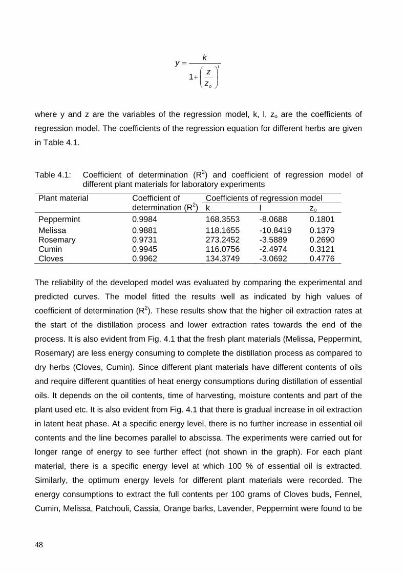
48
l
ozz
ky
⎟⎟⎠
⎞⎜⎜⎝
⎛+
=
1
where y and z are the variables of the regression model, k, l, zo are the coefficients of
regression model. The coefficients of the regression equation for different herbs are given
in Table 4.1.
Table 4.1: Coefficient of determination (R2) and coefficient of regression model of different plant materials for laboratory experiments
Plant material Coefficient of determination (R2)
Coefficients of regression model k l zo
Peppermint 0.9984 168.3553 -8.0688 0.1801 Melissa 0.9881 118.1655 -10.8419 0.1379 Rosemary 0.9731 273.2452 -3.5889 0.2690 Cumin 0.9945 116.0756 -2.4974 0.3121 Cloves 0.9962 134.3749 -3.0692 0.4776
The reliability of the developed model was evaluated by comparing the experimental and
predicted curves. The model fitted the results well as indicated by high values of
coefficient of determination (R2). These results show that the higher oil extraction rates at
the start of the distillation process and lower extraction rates towards the end of the
process. It is also evident from Fig. 4.1 that the fresh plant materials (Melissa, Peppermint,
Rosemary) are less energy consuming to complete the distillation process as compared to
dry herbs (Cloves, Cumin). Since different plant materials have different contents of oils
and require different quantities of heat energy consumptions during distillation of essential
oils. It depends on the oil contents, time of harvesting, moisture contents and part of the
plant used etc. It is also evident from Fig. 4.1 that there is gradual increase in oil extraction
in latent heat phase. At a specific energy level, there is no further increase in essential oil
contents and the line becomes parallel to abscissa. The experiments were carried out for
longer range of energy to see further effect (not shown in the graph). For each plant
material, there is a specific energy level at which 100 % of essential oil is extracted.
Similarly, the optimum energy levels for different plant materials were recorded. The
energy consumptions to extract the full contents per 100 grams of Cloves buds, Fennel,
Cumin, Melissa, Patchouli, Cassia, Orange barks, Lavender, Peppermint were found to be
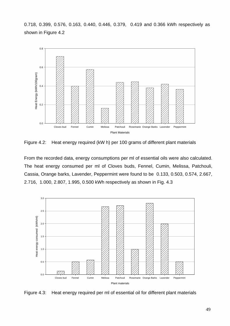
49
0.718, 0.399, 0.576, 0.163, 0.440, 0.446, 0.379, 0.419 and 0.366 kWh respectively as
shown in Figure 4.2
Plant Materials
Cloves bud Fennel Cumin Melissa Patchouli Rosemarie Orange Barks Lavender Peppermint
Hea
t Ene
rgy
(kW
h/10
0gra
m)
0.0
0.2
0.4
0.6
0.8
Figure 4.2: Heat energy required (kW h) per 100 grams of different plant materials From the recorded data, energy consumptions per ml of essential oils were also calculated.
The heat energy consumed per ml of Cloves buds, Fennel, Cumin, Melissa, Patchouli,
Cassia, Orange barks, Lavender, Peppermint were found to be 0.133, 0.503, 0.574, 2.667,
2.716, 1.000, 2.807, 1.995, 0.500 kWh respectively as shown in Fig. 4.3
Plant materials
Cloves bud Fennel Cumin Melissa Patchouli Rosemarie Orange Barks Lavender Peppermint
Hea
t ene
rgy
cons
umed
(kW
h/m
l)
0.0
0.5
1.0
1.5
2.0
2.5
3.0
Figure 4.3: Heat energy required per ml of essential oil for different plant materials

50
These results show that 1.63 to 7.18 kWh heat energy is required per kg of the plant
material for the experiments using laboratory apparatus. It is also concluded that the fresh
herbs consume less energy comparatively. As the study is focused for the on-farm
installation of solar distillation system of the fresh medicinal and aromatic plants, about 16
kWh heat energy is required to process 10 kg of plant material which can be utilized by
using an 8 m2 Scheffler reflector at 50 % efficiency during sunny days. These results
provide useful information in adopting appropriate distillation parameters to process the
herbs at farm. These results also lead to the development of solar distillation system. From
the laboratory experiments, it was found that successful distillation experiments can be
carried out by using a still, condenser, Florentine flask and a heat source. In order to apply
this technology for field experiments, the solar energy was selected as a heat source for the
distillation experiments. The main object of the study is to use the solar energy in a simple
and easy way that it can be used like a conventional heat source for the distillation system.
For this purpose, Scheffler fixed focus concentrator was used to adopt this technology at
farm level by using solar energy. The design and development details of this solar based
distillation system have been explained.
4.2 Design principle and mathematical calculations of Scheffler fixed focus concentrator
The solar distillation prototype for the processing of medicinal and aromatic plants was
designed and developed by using an 8 m2 surface area of Scheffler fixed focus
concentrator. The complete solar unit was constructed in the Agricultural Engineering
workshop, university of Kassel, Deula, Witzenhausen, Germany. Being a lateral part of a
paraboloid, the design of Scheffler fixed focus concentrator is the most complicated and
sophisticated component of the complete solar distillation system. Up to now, no
mathematical description of the design of Scheffler reflector has been done. The
manuscript explains the complete principle and mathematical calculations to design an 8
m2 Scheffler concentrator for the development of a solar distillation system.
4.2.1 Design of reflector parabola and reflector elliptical frame Unlike conventional paraboloid concentrator, Scheffler fixed focus concentrator is a lateral
part of a paraboloid as shown in Fig. 4.4.
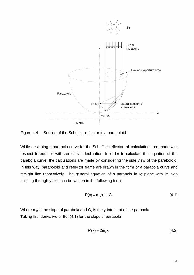
51
Focus
Available aperture area
Lateral section of a paraboloid
Paraboloid
VertexX
Y
Directrix
Beamradiations
Sun
Figure 4.4: Section of the Scheffler reflector in a paraboloid
While designing a parabola curve for the Scheffler reflector, all calculations are made with
respect to equinox with zero solar declination. In order to calculate the equation of the
parabola curve, the calculations are made by considering the side view of the paraboloid.
In this way, paraboloid and reflector frame are drawn in the form of a parabola curve and
straight line respectively. The general equation of a parabola in xy-plane with its axis
passing through y-axis can be written in the following form:
p2
p CxmP(x) += (4.1)
Where mp is the slope of parabola and Cp is the y-intercept of the parabola
Taking first derivative of Eq. (4.1) for the slope of parabola
x2m(x)P p=′ (4.2)
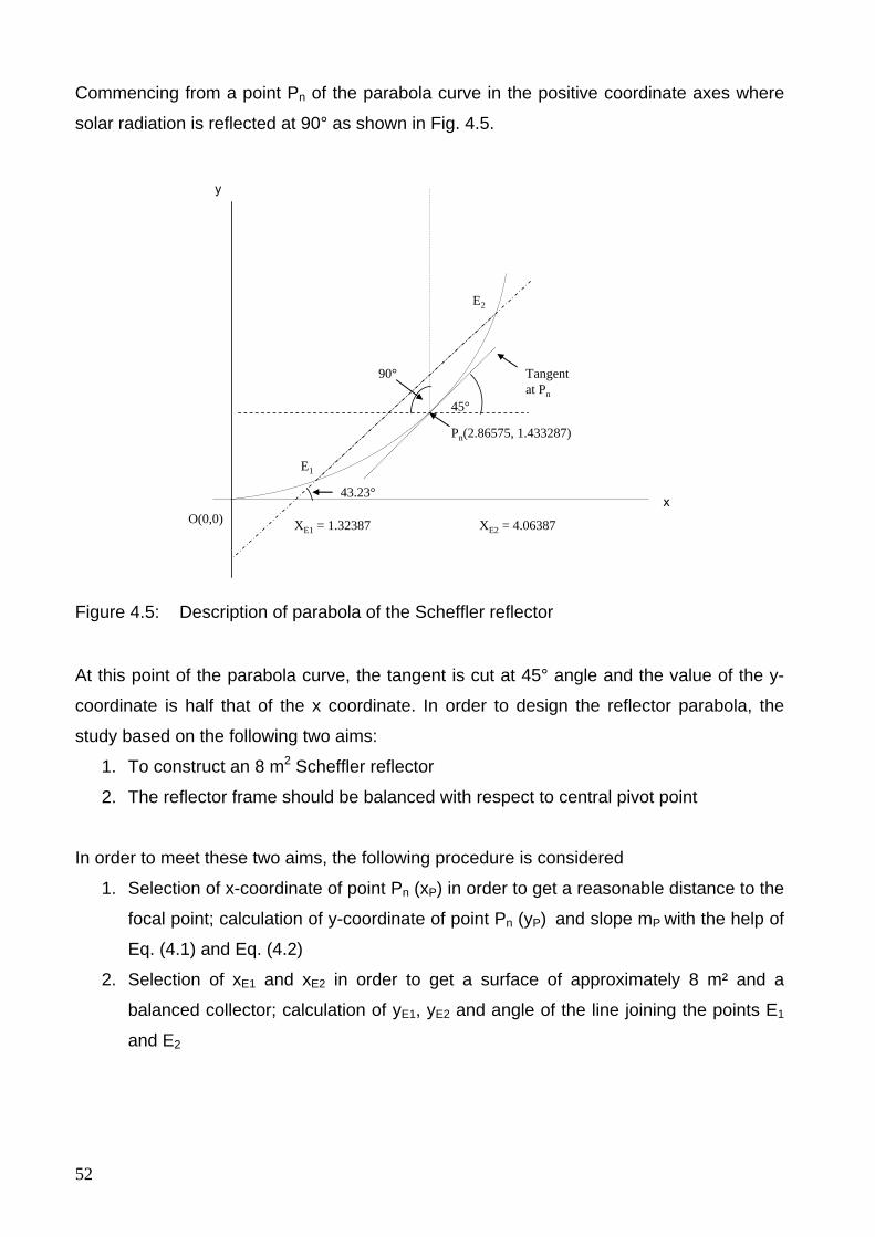
52
Commencing from a point Pn of the parabola curve in the positive coordinate axes where
solar radiation is reflected at 90° as shown in Fig. 4.5.
45°
43.23°
XE1 = 1.32387 XE2 = 4.06387
Pn(2.86575, 1.433287)
90° Tangentat Pn
E2
E1
O(0,0)x
y
Figure 4.5: Description of parabola of the Scheffler reflector
At this point of the parabola curve, the tangent is cut at 45° angle and the value of the y-
coordinate is half that of the x coordinate. In order to design the reflector parabola, the
study based on the following two aims:
1. To construct an 8 m2 Scheffler reflector
2. The reflector frame should be balanced with respect to central pivot point
In order to meet these two aims, the following procedure is considered
1. Selection of x-coordinate of point Pn (xP) in order to get a reasonable distance to the
focal point; calculation of y-coordinate of point Pn (yP) and slope mP with the help of
Eq. (4.1) and Eq. (4.2)
2. Selection of xE1 and xE2 in order to get a surface of approximately 8 m² and a
balanced collector; calculation of yE1, yE2 and angle of the line joining the points E1
and E2
53
3. Check if the two aims are roughly reached (calculation of surface area right and left
of Pm
and check their difference for balancing and their sum for collector surface);
otherwise adapt a new set of Pn, E1 and E2
4. Calculation of semi-major and semi-minor axis of the reflector frame
For a surface area of 8 m2, this point is taken as P (2.86575). This point varies with
different sizes of surface areas of Scheffler reflector. For a parabola of a 3.93 m2, this
point, where the reflection is 90°, is (2,1). The first derivative of Eq. (4.1) at this point is
equal to slope at the point. The tangent cuts this point Pn at an angle of 45° with x-axis
(directrix), so we can write:
( ) °45=865752′ tan.P
( ) 1=865752′ .P
According to definition of parabola, the coordinates at point Pn are given as
( ) ( )( )86575221=865752 ..P
( ) 432871=865752 ..P
By using Eq. (4.1) and Eq. (4.2), the values of mp and Cp are calculated as 0.17447 and 0
respectively. The parabola equation for the equinox is given as:
( ) 2174470 x.xP = (4.3)
In order to approximately construct a balanced reflector (8 m2 surface area), two points xE1
and xE2 are chosen on a graph paper as 1.32387 and 4.06387. The reason of selecting
these points is to construct a balanced parabola in order to rotate the reflector with a
nominal force. In this way, the line joining these two points E1 and E2 of the parabola curve
represents the cutting section of the elliptical frame of the Scheffler reflector. This line E1E2
is not parallel to the tangent at point Pn (which makes 45° angle with x-axis) but makes a
43.23° angle as shown in Fig. 4.5. The structure is equilibrated and needs a little force to
move the reflector. The general equation of this straight line is given by:
54
gg Cxm)x(G += (4.4)
Differentiating Eq. (4.4) with respect to x
( ) gmxG =′
°2343= .tanmg
( ) °2343=′ .tanxG
940= .mg
The coordinate x of point E1 (xE1) is selected to be 1.32387 and the coordinate y is
calculated to be 0.31 by using Eq. (4.4). By substituting the values of x, y and mg in Eq.
(4.4), the y-intercept (Cg) is calculated to be −0.94 and the equation of the straight line
becomes:
( ) 938660940 .x.xG −= (4.5)
The coordinate x of point E2 (xE2) is calculated by comparing and solving Eq. (4.1) and
(4.4), the general form of a quadratic equation is as follows:
p
gp
p
g
mCC
xmm
x−
+⎟⎟⎠
⎞⎜⎜⎝
⎛−2 (4.6)
Through solving Eq. (4.6) with the help of a quadratic formula to get two points of
intersection (xE1 and xE2) of the parabola curve and straight line, we get:
p
gp
p
g
p
gE m
CCm
mmm
x−
−⎟⎟⎠
⎞⎜⎜⎝
⎛+=
2
1 22 (4.7)
p
gp
p
g
p
gE m
CCm
mm
mx
−−⎟
⎟⎠
⎞⎜⎜⎝
⎛−=
2
2 22 (4.8)
55
The straight line cutting the curve represents a cutting plane of an ellipse with axes ratio
a/b = cos α, where “a” and “b” are the semi-minor axis and semi-major axis respectively.
For a given paraboloid, the cutting section of the lateral part will make an ellipse and its
projection on the ground (horizontal plane) will make a circle. So, the semi-minor axis of
the ellipse and radius of projection on the ground will become the same. The projection of
this ellipse on the horizontal plane (xz-plane) is a circle with a diameter of 2a. The general
equation for the diameter of circle (2a) is calculated for a Scheffler reflector by subtracting
Eq. (4.8) from Eq. (4.7) and is given by:
( )p
gp
p
g
mCC
mm
.a−
−⎟⎟⎠
⎞⎜⎜⎝
⎛=
2
222 (4.9)
The semi-minor axis of the ellipse is 1.37000 m and semi-major axis of the reflector is
calculated to be 1.88029 m by dividing with axes ratio (cos 43.23).
4.2.2 Distribution of crossbars on the reflector frame For the construction of a Scheffler reflector, it is necessary to know the exact position of
the crossbars on the reflector frame. The frame of Scheffler reflector is elliptical in shape
and this can easily be calculated by using the equation of ellipse which is given below:
122
=⎟⎠⎞
⎜⎝⎛+⎟
⎠⎞
⎜⎝⎛
ay
bx (4.10)
where a is the semi-minor axis of the ellipse, b is the semi-major axis of the ellipse. In
order to locate any point “yn” with respect to “xn” on the elliptical frame, Eq. (4.10) can be
written as:
22nn xbcosy −= α (4.11)
Eq. (4.11) is used to calculate the position of the crossbars on the elliptical frame of the
Scheffler reflector. A number of points can be taken but seven crossbars are sufficient to
make the required section of the paraboloid for an 8 m2 Scheffler reflector. Taking the
centre of ellipse as origin and major axis along x-axis, the middle crossbar passes through
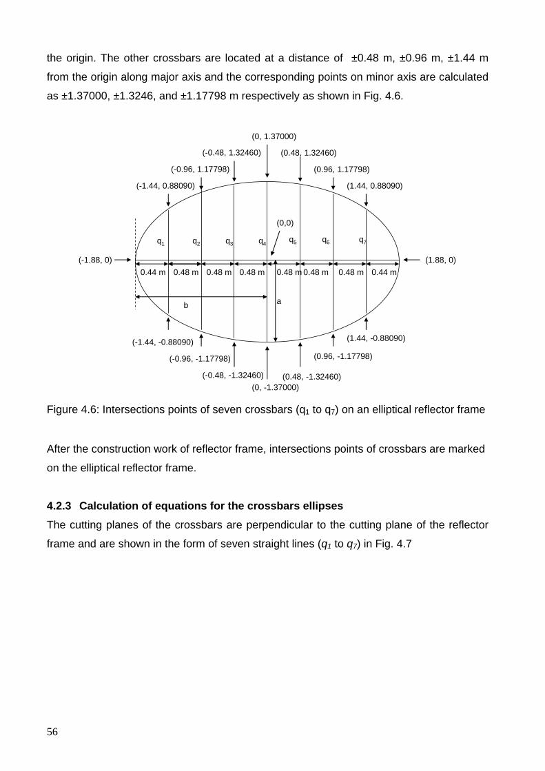
56
the origin. The other crossbars are located at a distance of ±0.48 m, ±0.96 m, ±1.44 m
from the origin along major axis and the corresponding points on minor axis are calculated
as ±1.37000, ±1.3246, and ±1.17798 m respectively as shown in Fig. 4.6.
(0, -1.37000)(0.48, -1.32460)
(1.44, -0.88090)
q1 q2
(0.96, -1.17798)
(1.88, 0)
(0, 1.37000)
(0.48, 1.32460)
(0.96, 1.17798)
(1.44, 0.88090)
(-0.48, 1.32460)
(-0.96, 1.17798)
(-1.44, 0.88090)
(-1.88, 0)
(-0.48, -1.32460)
(-0.96, -1.17798)
(-1.44, -0.88090)
0.48 m 0.48 m 0.48 m 0.48 m 0.48 m 0.44 m0.44 m
(0,0)
q3 q4 q5 q6 q7
0.48 m
ab
Figure 4.6: Intersections points of seven crossbars (q1 to q7) on an elliptical reflector frame
After the construction work of reflector frame, intersections points of crossbars are marked
on the elliptical reflector frame.
4.2.3 Calculation of equations for the crossbars ellipses The cutting planes of the crossbars are perpendicular to the cutting plane of the reflector
frame and are shown in the form of seven straight lines (q1 to q7) in Fig. 4.7
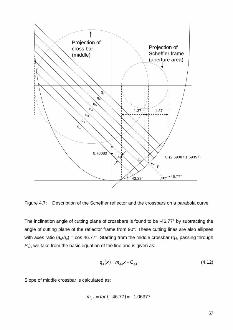
57
q4
43.23° 46.77°
1.371.37
Projection ofScheffler frame(aperture area)
Projection of cross bar (middle)
q1
q3
q2
q5
q7
q6
Pc
Cf (2.69387,1.59357)Cf0.48
0.70080
Figure 4.7: Description of the Scheffler reflector and the crossbars on a parabola curve
The inclination angle of cutting plane of crossbars is found to be -46.77° by subtracting the
angle of cutting plane of the reflector frame from 90°. These cutting lines are also ellipses
with axes ratio (aq/bq) = cos 46.77°. Starting from the middle crossbar (q4, passing through
Pc), we take from the basic equation of the line and is given as:
( ) 444 qq Cxmxq += (4.12)
Slope of middle crossbar is calculated as:
( ) 06377177464 ..tanmq −=−=
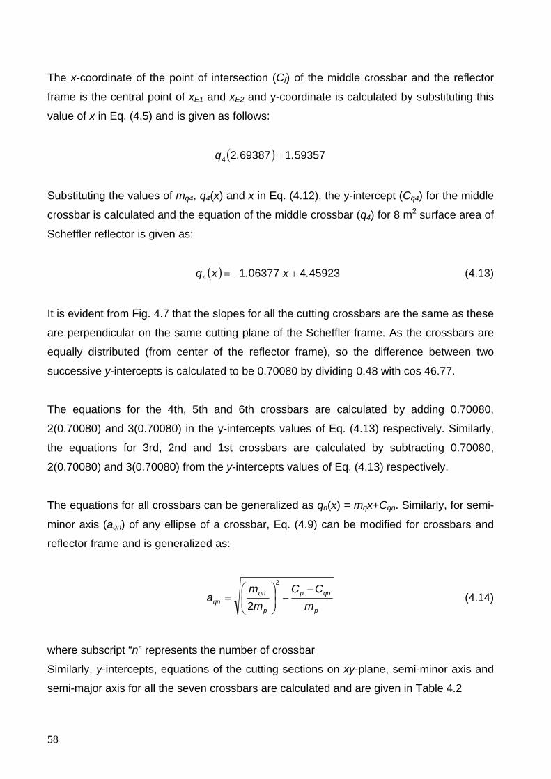
58
The x-coordinate of the point of intersection (Cf) of the middle crossbar and the reflector
frame is the central point of xE1 and xE2 and y-coordinate is calculated by substituting this
value of x in Eq. (4.5) and is given as follows:
( ) 5935716938724 ..q =
Substituting the values of mq4, q4(x) and x in Eq. (4.12), the y-intercept (Cq4) for the middle
crossbar is calculated and the equation of the middle crossbar (q4) for 8 m2 surface area of
Scheffler reflector is given as:
( ) 4592340637714 .x.xq +−= (4.13)
It is evident from Fig. 4.7 that the slopes for all the cutting crossbars are the same as these
are perpendicular on the same cutting plane of the Scheffler frame. As the crossbars are
equally distributed (from center of the reflector frame), so the difference between two
successive y-intercepts is calculated to be 0.70080 by dividing 0.48 with cos 46.77.
The equations for the 4th, 5th and 6th crossbars are calculated by adding 0.70080,
2(0.70080) and 3(0.70080) in the y-intercepts values of Eq. (4.13) respectively. Similarly,
the equations for 3rd, 2nd and 1st crossbars are calculated by subtracting 0.70080,
2(0.70080) and 3(0.70080) from the y-intercepts values of Eq. (4.13) respectively.
The equations for all crossbars can be generalized as qn(x) = mqx+Cqn. Similarly, for semi-
minor axis (aqn) of any ellipse of a crossbar, Eq. (4.9) can be modified for crossbars and
reflector frame and is generalized as:
p
qnp
p
qnqn m
CCm
ma
−−⎟
⎟⎠
⎞⎜⎜⎝
⎛=
2
2 (4.14)
where subscript “n” represents the number of crossbar
Similarly, y-intercepts, equations of the cutting sections on xy-plane, semi-minor axis and
semi-major axis for all the seven crossbars are calculated and are given in Table 4.2
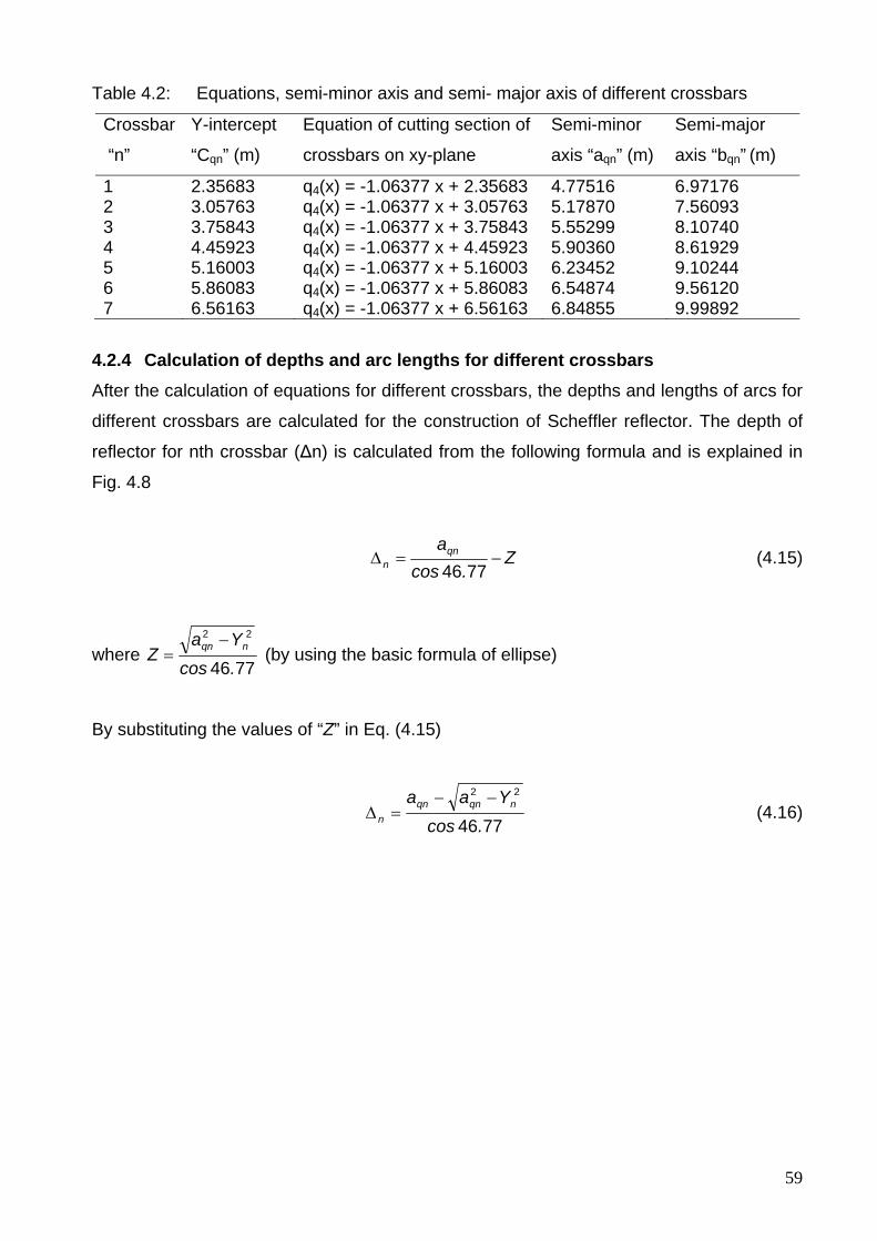
59
Table 4.2: Equations, semi-minor axis and semi- major axis of different crossbars
Crossbar
“n”
Y-intercept
“Cqn” (m)
Equation of cutting section of
crossbars on xy-plane
Semi-minor
axis “aqn” (m)
Semi-major
axis “bqn” (m)
1 2.35683 q4(x) = -1.06377 x + 2.35683 4.77516 6.97176 2 3.05763 q4(x) = -1.06377 x + 3.05763 5.17870 7.56093 3 3.75843 q4(x) = -1.06377 x + 3.75843 5.55299 8.10740 4 4.45923 q4(x) = -1.06377 x + 4.45923 5.90360 8.61929 5 5.16003 q4(x) = -1.06377 x + 5.16003 6.23452 9.10244 6 5.86083 q4(x) = -1.06377 x + 5.86083 6.54874 9.56120 7 6.56163 q4(x) = -1.06377 x + 6.56163 6.84855 9.99892
4.2.4 Calculation of depths and arc lengths for different crossbars After the calculation of equations for different crossbars, the depths and lengths of arcs for
different crossbars are calculated for the construction of Scheffler reflector. The depth of
reflector for nth crossbar (Δn) is calculated from the following formula and is explained in
Fig. 4.8
Z.cos
aqnn −=Δ
7746 (4.15)
where 7746
22
.cosYa
Z nqn −= (by using the basic formula of ellipse)
By substituting the values of “Z” in Eq. (4.15)
7746
22
.cosYaa nqnqn
n
−−=Δ (4.16)
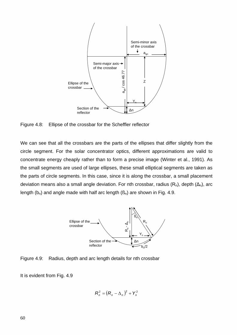
60
aqn
Z
Δn
a qn
/ cos
46.
77
Yn
Ellipse of thecrossbar
Section of thereflector
Semi-minor axis of the crossbar
Semi-major axis of the crossbar
Figure 4.8: Ellipse of the crossbar for the Scheffler reflector
We can see that all the crossbars are the parts of the ellipses that differ slightly from the
circle segment. For the solar concentrator optics, different approximations are valid to
concentrate energy cheaply rather than to form a precise image (Winter et al., 1991). As
the small segments are used of large ellipses, these small elliptical segments are taken as
the parts of circle segments. In this case, since it is along the crossbar, a small placement
deviation means also a small angle deviation. For nth crossbar, radius (Rn), depth (Δn), arc
length (bn) and angle made with half arc length (ßn) are shown in Fig. 4.9.
Δn
Yn
Ellipse of thecrossbar
Section of thereflector bn/2
ßn
Rn
-Δn Rn
Figure 4.9: Radius, depth and arc length details for nth crossbar
It is evident from Fig. 4.9
( ) 222nnnn YRR +Δ−=
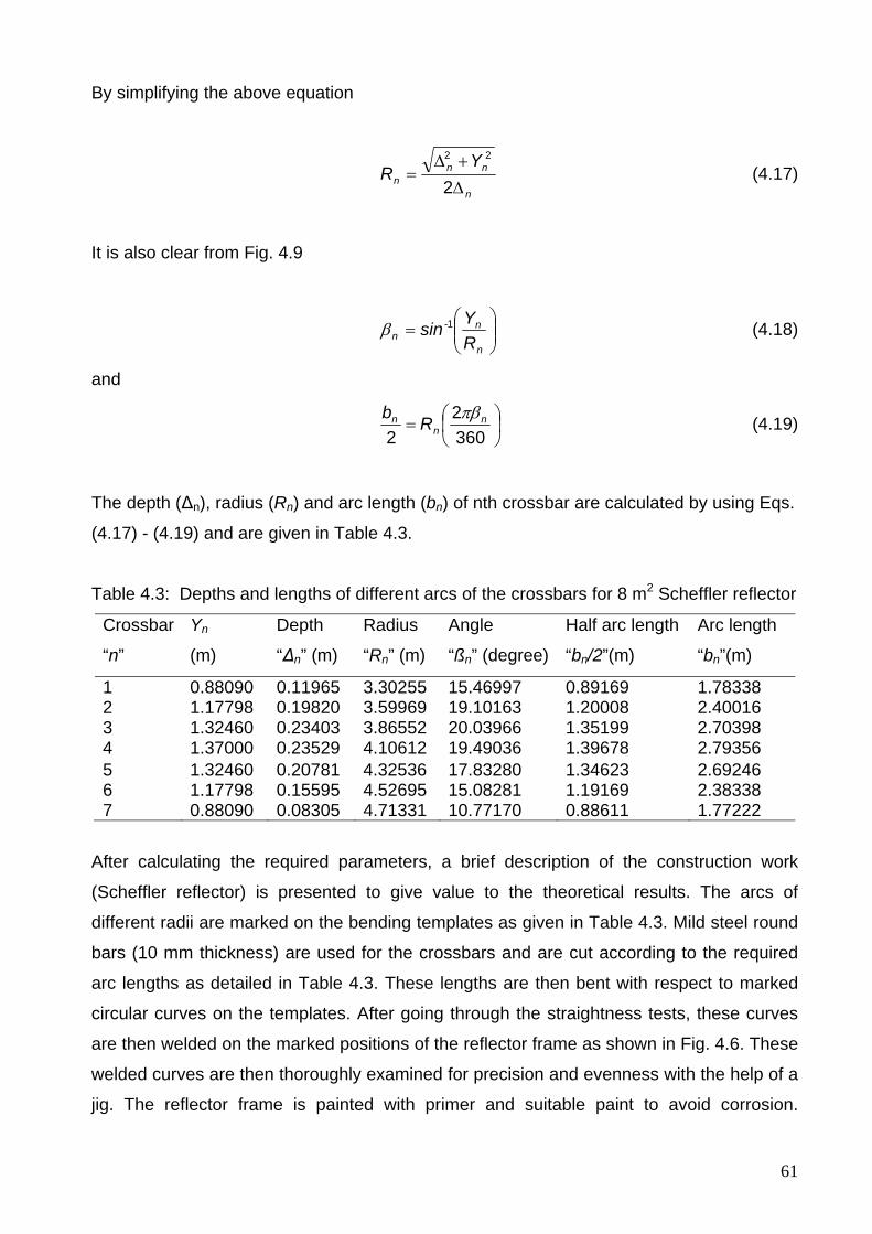
61
By simplifying the above equation
n
nnn
YR
Δ+Δ
=2
22
(4.17)
It is also clear from Fig. 4.9
⎟⎟⎠
⎞⎜⎜⎝
⎛=
n
nn R
Ysin 1-β (4.18)
and
⎟⎠⎞
⎜⎝⎛=
3602
2n
nn Rb πβ (4.19)
The depth (Δn), radius (Rn) and arc length (bn) of nth crossbar are calculated by using Eqs.
(4.17) - (4.19) and are given in Table 4.3.
Table 4.3: Depths and lengths of different arcs of the crossbars for 8 m2 Scheffler reflector
Crossbar
“n”
Yn
(m)
Depth
“Δn” (m)
Radius
“Rn” (m)
Angle
“ßn” (degree)
Half arc length
“bn/2”(m)
Arc length
“bn”(m)
1 0.88090 0.11965 3.30255 15.46997 0.89169 1.78338 2 1.17798 0.19820 3.59969 19.10163 1.20008 2.40016 3 1.32460 0.23403 3.86552 20.03966 1.35199 2.70398 4 1.37000 0.23529 4.10612 19.49036 1.39678 2.79356 5 1.32460 0.20781 4.32536 17.83280 1.34623 2.69246 6 1.17798 0.15595 4.52695 15.08281 1.19169 2.38338 7 0.88090 0.08305 4.71331 10.77170 0.88611 1.77222
After calculating the required parameters, a brief description of the construction work
(Scheffler reflector) is presented to give value to the theoretical results. The arcs of
different radii are marked on the bending templates as given in Table 4.3. Mild steel round
bars (10 mm thickness) are used for the crossbars and are cut according to the required
arc lengths as detailed in Table 4.3. These lengths are then bent with respect to marked
circular curves on the templates. After going through the straightness tests, these curves
are then welded on the marked positions of the reflector frame as shown in Fig. 4.6. These
welded curves are then thoroughly examined for precision and evenness with the help of a
jig. The reflector frame is painted with primer and suitable paint to avoid corrosion.
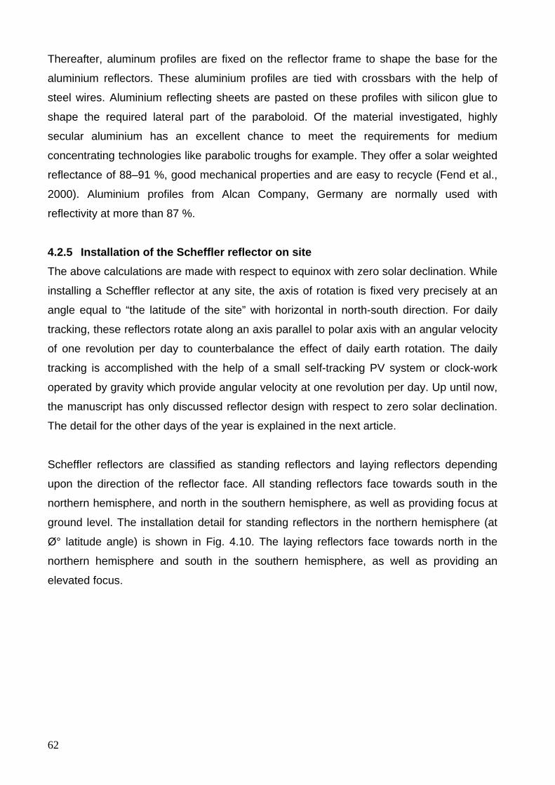
62
Thereafter, aluminum profiles are fixed on the reflector frame to shape the base for the
aluminium reflectors. These aluminium profiles are tied with crossbars with the help of
steel wires. Aluminium reflecting sheets are pasted on these profiles with silicon glue to
shape the required lateral part of the paraboloid. Of the material investigated, highly
secular aluminium has an excellent chance to meet the requirements for medium
concentrating technologies like parabolic troughs for example. They offer a solar weighted
reflectance of 88–91 %, good mechanical properties and are easy to recycle (Fend et al.,
2000). Aluminium profiles from Alcan Company, Germany are normally used with
reflectivity at more than 87 %.
4.2.5 Installation of the Scheffler reflector on site The above calculations are made with respect to equinox with zero solar declination. While
installing a Scheffler reflector at any site, the axis of rotation is fixed very precisely at an
angle equal to “the latitude of the site” with horizontal in north-south direction. For daily
tracking, these reflectors rotate along an axis parallel to polar axis with an angular velocity
of one revolution per day to counterbalance the effect of daily earth rotation. The daily
tracking is accomplished with the help of a small self-tracking PV system or clock-work
operated by gravity which provide angular velocity at one revolution per day. Up until now,
the manuscript has only discussed reflector design with respect to zero solar declination.
The detail for the other days of the year is explained in the next article.
Scheffler reflectors are classified as standing reflectors and laying reflectors depending
upon the direction of the reflector face. All standing reflectors face towards south in the
northern hemisphere, and north in the southern hemisphere, as well as providing focus at
ground level. The installation detail for standing reflectors in the northern hemisphere (at
Ø° latitude angle) is shown in Fig. 4.10. The laying reflectors face towards north in the
northern hemisphere and south in the southern hemisphere, as well as providing an
elevated focus.
63
B
Seasonal tracking (Telescopic clamps)
LatitudeAngle of the site Ø °
Reflectorstand
Axis of rotationAngular velocity 1 rev/dayEast to West
Fixed focus (F)
N
S
E
W
☼
Location of Scheffler Reflectorat latitude Ø °
Ø °
Polar axisAngular velocity 1 rev/dayWest to East
Daily tracking device
Parallel axis of rotation
Earth
Figure 4.10: Installation and daily tracking details of the Scheffler reflector (valid for standing reflectors in the northern hemisphere)
4.2.6 Daily tracking Both standing and laying reflectors rotate along their axis of rotation with an angular
velocity of one revolution per day to counterbalance the effect of daily earth rotation. The
tracking mechanism normally comprises of small self-tracking PV system or clock-work
operated by gravity. In clock-work system, a weight pulled the reflector with the help of a
string due to force of gravity through tracking channel. The pendulum of clock mechanism
maintains the angular velocity of one revolution per day to counter balance the effect of
earth rotation. Performance evaluation and distillation experiments were carried out by
both clock-work tracking system and PV tracking system. Out of the two methods, exact
results were obtained by PV tracking system. In fact, this system is based on the actual
sensing of the sun position and more realistic tracking approach. It comprises of two
aluminum plates to form a v-shape angle (51°). Four small photovoltaic panels (each
having 0.5 volts, 300 mA) are pasted on aluminum plates (two on either side) and covered
by cylindrical glass. This glass behaves like a lens and produces concentrated line image
for precise tracking. The changing position of the sun causes a current difference in two
PV plated which actuates the DC geared motor. The structure of primary reflector is
completely balanced and need very low power to track the sun. In this way, the primary
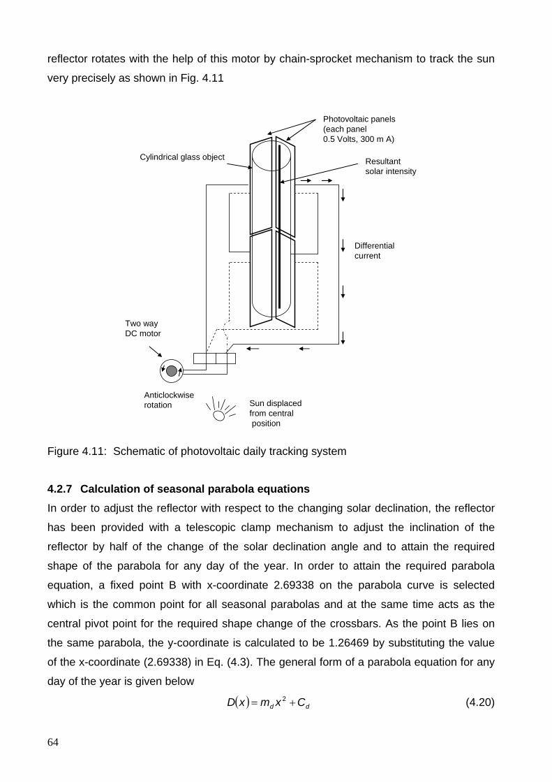
64
reflector rotates with the help of this motor by chain-sprocket mechanism to track the sun
very precisely as shown in Fig. 4.11
Anticlockwiserotation
Photovoltaic panels(each panel 0.5 Volts, 300 m A)
Cylindrical glass object Resultant solar intensity
Two wayDC motor
Differentialcurrent
Sun displaced from centralposition
Figure 4.11: Schematic of photovoltaic daily tracking system
4.2.7 Calculation of seasonal parabola equations In order to adjust the reflector with respect to the changing solar declination, the reflector
has been provided with a telescopic clamp mechanism to adjust the inclination of the
reflector by half of the change of the solar declination angle and to attain the required
shape of the parabola for any day of the year. In order to attain the required parabola
equation, a fixed point B with x-coordinate 2.69338 on the parabola curve is selected
which is the common point for all seasonal parabolas and at the same time acts as the
central pivot point for the required shape change of the crossbars. As the point B lies on
the same parabola, the y-coordinate is calculated to be 1.26469 by substituting the value
of the x-coordinate (2.69338) in Eq. (4.3). The general form of a parabola equation for any
day of the year is given below
( ) dd CxmxD += 2 (4.20)
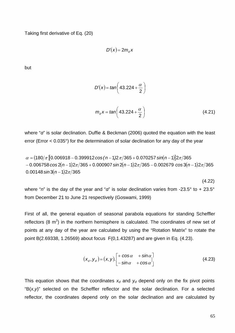
65
Taking first derivative of Eq. (20)
( ) xmxD d2=′
but
( ) ⎟⎠⎞
⎜⎝⎛ +=′
222443 α.tanxD
⎟⎠⎞
⎜⎝⎛ +=
222443 α.tanxmd (4.21)
where “α” is solar declination. Duffie & Beckman (2006) quoted the equation with the least
error (Error < 0.035°) for the determination of solar declination for any day of the year
( ) ( )[ ]( ) ( ) ( )
( ) 365213001480365213002679036521200090703652120067580
3652107025703652139991200069180180
ππππ
πππα
−−−−+−−
−+−−=
nsin.ncos.nsin.ncos.
nsin.)n(cos..
(4.22)
where “n” is the day of the year and “α” is solar declination varies from -23.5° to + 23.5°
from December 21 to June 21 respectively (Goswami, 1999)
First of all, the general equation of seasonal parabola equations for standing Scheffler
reflectors (8 m2) in the northern hemisphere is calculated. The coordinates of new set of
points at any day of the year are calculated by using the “Rotation Matrix” to rotate the
point B(2.69338, 1.26569) about focus F(0,1.43287) and are given in Eq. (4.23).
( ) ( ) ⎥⎦
⎤⎢⎣
⎡+−++
=αααα
cossinsincos
.y,xy,x dd (4.23)
This equation shows that the coordinates xd and yd depend only on the fix pivot points
“B(x,y)” selected on the Scheffler reflector and the solar declination. For a selected
reflector, the coordinates depend only on the solar declination and are calculated by
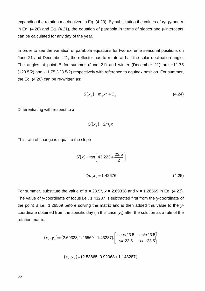
66
expanding the rotation matrix given in Eq. (4.23). By substituting the values of xd, yd and α
in Eq. (4.20) and Eq. (4.21), the equation of parabola in terms of slopes and y-intercepts
can be calculated for any day of the year.
In order to see the variation of parabola equations for two extreme seasonal positions on
June 21 and December 21, the reflector has to rotate at half the solar declination angle.
The angles at point B for summer (June 21) and winter (December 21) are +11.75
(+23.5/2) and -11.75 (-23.5/2) respectively with reference to equinox position. For summer,
the Eq. (4.20) can be re-written as:
( ) sss CxmxS += 2 (4.24)
Differentiating with respect to x
( ) xmxS ss 2=′
This rate of change is equal to the slope
( ) ⎟⎠⎞
⎜⎝⎛ +=′
252322343 ..tanxS
4267612 .xm ss = (4.25)
For summer, substitute the value of α = 23.5°, x = 2.69338 and y = 1.26569 in Eq. (4.23).
The value of y-coordinate of focus i.e., 1.43287 is subtracted first from the y-coordinate of
the point B i.e., 1.26569 before solving the matrix and is then added this value to the y-
coordinate obtained from the specific day (in this case, ys) after the solution as a rule of the
rotation matrix.
( ) ( ) ⎥⎦
⎤⎢⎣
⎡+−++
−=523523523523
432871265691693382.cos.sin.sin.cos
...,.y,x ss
( ) ( )1432871920680536652 ..,.y,x ss +=
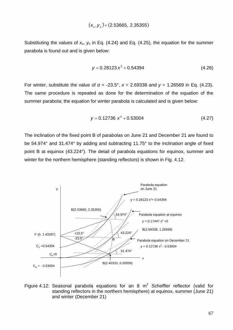
67
( ) ( )353552536652 .,.`y,x ss =
Substituting the values of xs, ys in Eq. (4.24) and Eq. (4.25), the equation for the summer
parabola is found out and is given below:
543940281230 2 .x.y += (4.26)
For winter, substitute the value of α = -23.5°, x = 2.69338 and y = 1.26569 in Eq. (4.23).
The same procedure is repeated as done for the determination of the equation of the
summer parabola; the equation for winter parabola is calculated and is given below:
530040127360 2 .x.y += (4.27)
The inclination of the fixed point B of parabolas on June 21 and December 21 are found to
be 54.974° and 31.474° by adding and subtracting 11.75° to the inclination angle of fixed
point B at equinox (43.224°). The detail of parabola equations for equinox, summer and
winter for the northern hemisphere (standing reflectors) is shown in Fig. 4.12.
43.224°
31.474°
54.974°
+23.5°-23.5°
x
yParabola equation on June 21
Parabola equation at equinox
Parabola equation on December 21B
Cs =0.54394
Cw = - 0.53004
Ce=0
F (0, 1.43287)
B(2.53665, 2.35355)
y = 0.28123 x2+ 0.54394
y = 0.12736 x2 - 0.53004
B(2.69338, 1.26569)
y = 0.17447 x2 +0
B(2.40333, 0.20559)
Figure 4.12: Seasonal parabola equations for an 8 m2 Scheffler reflector (valid for standing reflectors in the northern hemisphere) at equinox, summer (June 21) and winter (December 21)
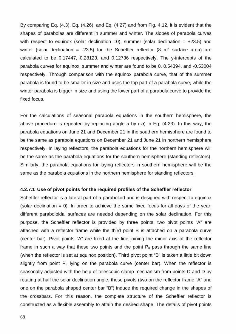
68
By comparing Eq. (4.3), Eq. (4.26), and Eq. (4.27) and from Fig. 4.12, it is evident that the
shapes of parabolas are different in summer and winter. The slopes of parabola curves
with respect to equinox (solar declination =0), summer (solar declination = +23.5) and
winter (solar declination = -23.5) for the Scheffler reflector (8 m2 surface area) are
calculated to be 0.17447, 0.28123, and 0.12736 respectively. The y-intercepts of the
parabola curves for equinox, summer and winter are found to be 0, 0.54394, and -0.53004
respectively. Through comparison with the equinox parabola curve, that of the summer
parabola is found to be smaller in size and uses the top part of a parabola curve, while the
winter parabola is bigger in size and using the lower part of a parabola curve to provide the
fixed focus.
For the calculations of seasonal parabola equations in the southern hemisphere, the
above procedure is repeated by replacing angle α by (-α) in Eq. (4.23). In this way, the
parabola equations on June 21 and December 21 in the southern hemisphere are found to
be the same as parabola equations on December 21 and June 21 in northern hemisphere
respectively. In laying reflectors, the parabola equations for the northern hemisphere will
be the same as the parabola equations for the southern hemisphere (standing reflectors).
Similarly, the parabola equations for laying reflectors in southern hemisphere will be the
same as the parabola equations in the northern hemisphere for standing reflectors.
4.2.7.1 Use of pivot points for the required profiles of the Scheffler reflector Scheffler reflector is a lateral part of a paraboloid and is designed with respect to equinox
(solar declination = 0). In order to achieve the same fixed focus for all days of the year,
different paraboloidal surfaces are needed depending on the solar declination. For this
purpose, the Scheffler reflector is provided by three points, two pivot points “A” are
attached with a reflector frame while the third point B is attached on a parabola curve
(center bar). Pivot points “A” are fixed at the line joining the minor axis of the reflector
frame in such a way that these two points and the point Pn pass through the same line
(when the reflector is set at equinox position). Third pivot point “B” is taken a little bit down
slightly from point Pn lying on the parabola curve (center bar). When the reflector is
seasonally adjusted with the help of telescopic clamp mechanism from points C and D by
rotating at half the solar declination angle, these pivots (two on the reflector frame “A” and
one on the parabola shaped center bar “B”) induce the required change in the shapes of
the crossbars. For this reason, the complete structure of the Scheffler reflector is
constructed as a flexible assembly to attain the desired shape. The details of pivot points
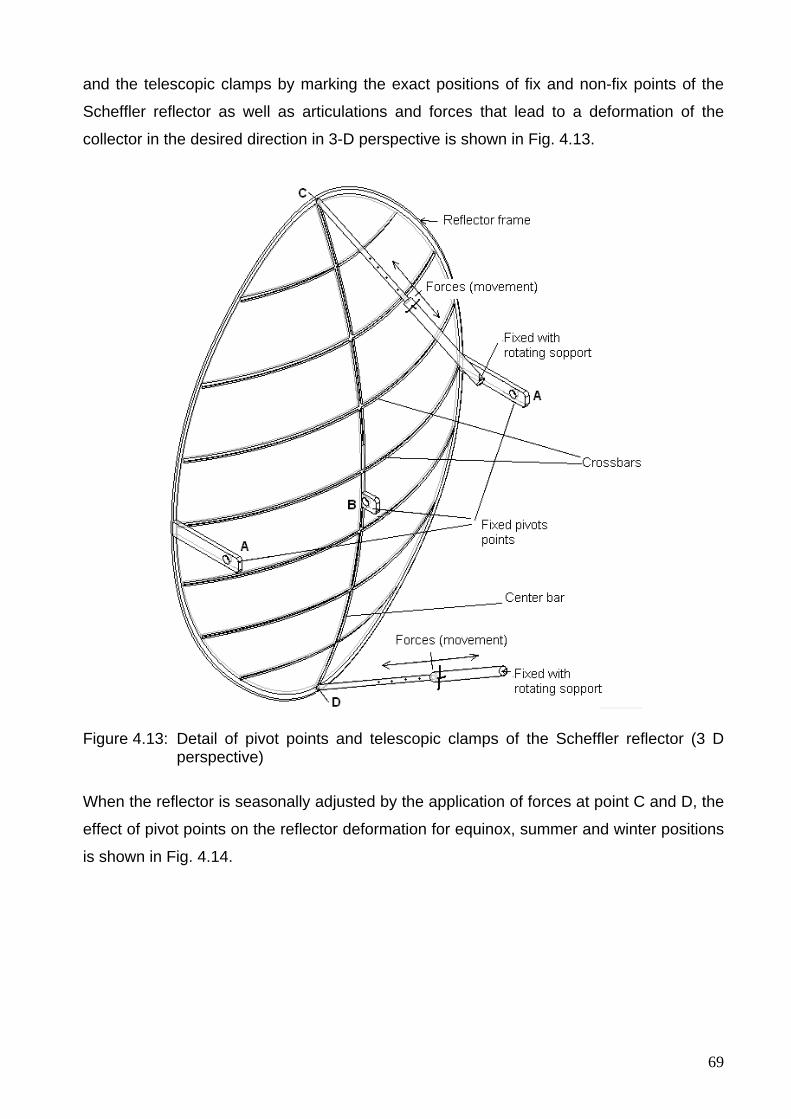
69
and the telescopic clamps by marking the exact positions of fix and non-fix points of the
Scheffler reflector as well as articulations and forces that lead to a deformation of the
collector in the desired direction in 3-D perspective is shown in Fig. 4.13.
Figure 4.13: Detail of pivot points and telescopic clamps of the Scheffler reflector (3 D perspective)
When the reflector is seasonally adjusted by the application of forces at point C and D, the
effect of pivot points on the reflector deformation for equinox, summer and winter positions
is shown in Fig. 4.14.
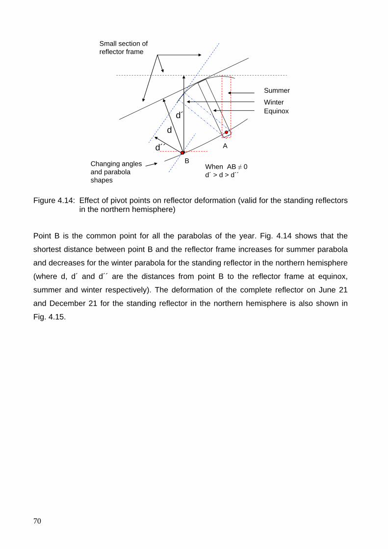
70
A
B
Small section of reflector frame
Changing anglesand parabola shapes
Summer
EquinoxWinter
d
d´
d´´
When AB ≠ 0d´ > d > d´´
Figure 4.14: Effect of pivot points on reflector deformation (valid for the standing reflectors in the northern hemisphere)
Point B is the common point for all the parabolas of the year. Fig. 4.14 shows that the
shortest distance between point B and the reflector frame increases for summer parabola
and decreases for the winter parabola for the standing reflector in the northern hemisphere
(where d, d´ and d´´ are the distances from point B to the reflector frame at equinox,
summer and winter respectively). The deformation of the complete reflector on June 21
and December 21 for the standing reflector in the northern hemisphere is also shown in
Fig. 4.15.
71
Figure 4.15: Functioning of pivot points and clamps to deform the reflector (valid for standing reflectors in the northern hemisphere)
It is evident from Fig. 4.15 that these pivot points also deform the shape of the reflector
frame, which are curved outside in the summer and curved inside in the winter for the
standing reflectors in the northern hemisphere. By using the three pivot points, in praxis
the approximately correct shape is attained for the curvature of the crossbars. Along the
parabola (center bar), the two telescopic clamps are used (at points C and D) to deform
the center bar until the concentrated light is the smallest at the focal point. This is not
perfect, but serves the intended purpose of heat utilization at the fixed focus in medium
temperature range.
The focus remains fixed and always lies on the line passing through the axis of rotation of
the primary reflector. The distance between two fixed points B and F always remain 2700
mm (for 8 m2 reflector design). In this way, the reflected beam remains aligned with the
fixed focus for all days of the year.
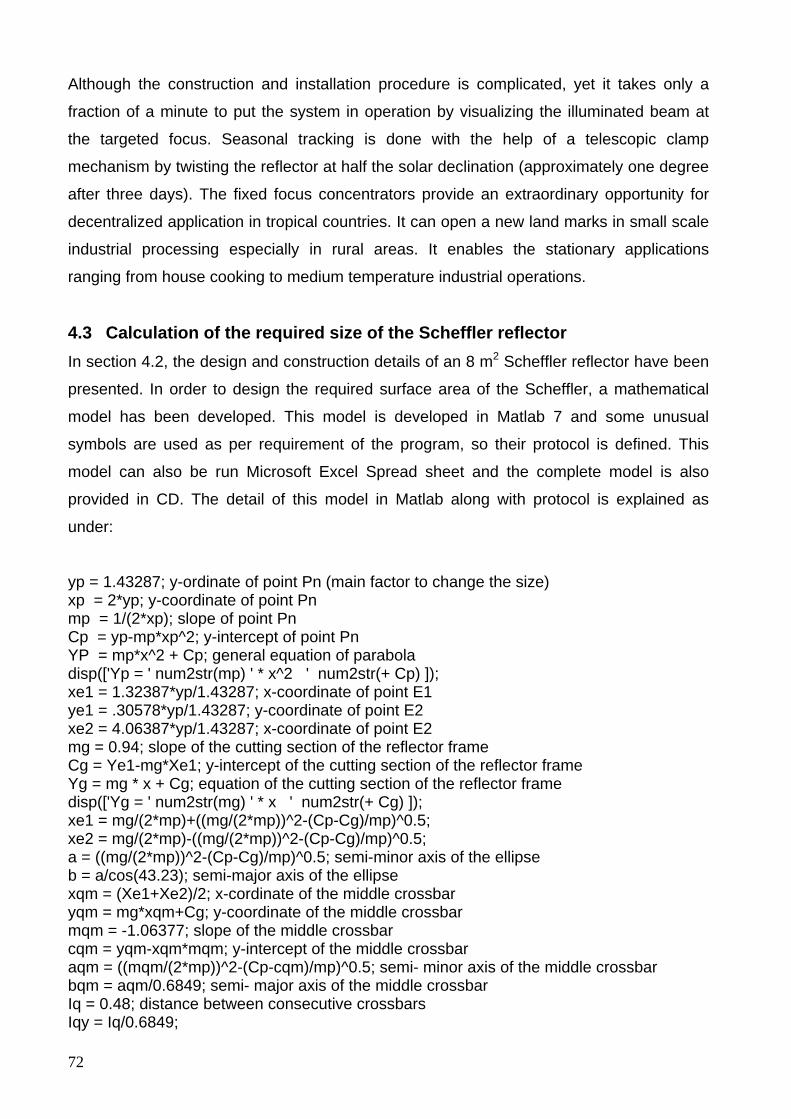
72
Although the construction and installation procedure is complicated, yet it takes only a
fraction of a minute to put the system in operation by visualizing the illuminated beam at
the targeted focus. Seasonal tracking is done with the help of a telescopic clamp
mechanism by twisting the reflector at half the solar declination (approximately one degree
after three days). The fixed focus concentrators provide an extraordinary opportunity for
decentralized application in tropical countries. It can open a new land marks in small scale
industrial processing especially in rural areas. It enables the stationary applications
ranging from house cooking to medium temperature industrial operations.
4.3 Calculation of the required size of the Scheffler reflector In section 4.2, the design and construction details of an 8 m2 Scheffler reflector have been
presented. In order to design the required surface area of the Scheffler, a mathematical
model has been developed. This model is developed in Matlab 7 and some unusual
symbols are used as per requirement of the program, so their protocol is defined. This
model can also be run Microsoft Excel Spread sheet and the complete model is also
provided in CD. The detail of this model in Matlab along with protocol is explained as
under:
yp = 1.43287; y-ordinate of point Pn (main factor to change the size) xp = 2*yp; y-coordinate of point Pn mp = 1/(2*xp); slope of point Pn Cp = yp-mp*xp^2; y-intercept of point Pn YP = mp*x^2 + Cp; general equation of parabola disp(['Yp = ' num2str(mp) ' * x^2 ' num2str(+ Cp) ]); xe1 = 1.32387*yp/1.43287; x-coordinate of point E1 ye1 = .30578*yp/1.43287; y-coordinate of point E2 xe2 = 4.06387*yp/1.43287; x-coordinate of point E2 mg = 0.94; slope of the cutting section of the reflector frame Cg = Ye1-mg*Xe1; y-intercept of the cutting section of the reflector frame Yg = mg * x + Cg; equation of the cutting section of the reflector frame disp(['Yg = ' num2str(mg) ' * x ' num2str(+ Cg) ]); xe1 = mg/(2*mp)+((mg/(2*mp))^2-(Cp-Cg)/mp)^0.5; xe2 = mg/(2*mp)-((mg/(2*mp))^2-(Cp-Cg)/mp)^0.5; a = ((mg/(2*mp))^2-(Cp-Cg)/mp)^0.5; semi-minor axis of the ellipse b = a/cos(43.23); semi-major axis of the ellipse xqm = (Xe1+Xe2)/2; x-cordinate of the middle crossbar yqm = mg*xqm+Cg; y-coordinate of the middle crossbar mqm = -1.06377; slope of the middle crossbar cqm = yqm-xqm*mqm; y-intercept of the middle crossbar aqm = ((mqm/(2*mp))^2-(Cp-cqm)/mp)^0.5; semi- minor axis of the middle crossbar bqm = aqm/0.6849; semi- major axis of the middle crossbar Iq = 0.48; distance between consecutive crossbars Iqy = Iq/0.6849;

73
nc = b/0.48; no. of crossbars required nf = fix(nc); for i = -nf:nf; cqm1 = cqm + i * Iqy; y-intercept of ith crossbar aqm1 = ((mqm/(2*mp))^2-(Cp-cqm1)/mp)^0.5; semi minor axis of ith crossbar bqm1 = aqm1/.6849; semi major axis of ith crossbar Yn = cos(43.23)*(b^2-(i*Iq)^2)^0.5; deln = (aqm1-(aqm1^2-Yn^2)^0.5)/cosd(46.77); reflector depth for ith crossbar Rn = (deln ^2+Yn^2)/(2*deln); radius of nth crossbar beta = 180/pi*asin(Yn/Rn); angle of ith crossbar bn = 2*Rn*beta*pi/180; half crossbar of ith crossbar disp(['Q' num2str(i) '= ' num2str(mqm) ' * x ' num2str(cqm1) ]); end qn = mqm*x +Cqm n = 110; no. of day of the year decl = 180/pi*(0.006918-0.399912*cos(2*pi/365*(n-1))... + 0.070257*sin(2*pi/365*(n-1))-0.006758*cos(2*(2*pi/365*(n-1)))... + 0.000907*sin(2*(2*pi/365*(n-1)))-0.002697*cos(3*(2*pi/365*(n-1)))... + 0.00148*sin(3*(2*pi/365*(n-1)))); solar declination on nth day of the year For northern hemisphere xdn = (2.69338*yp/1.43287)*cosd(decl)-(1.26569*yp/1.43287-1.43287)*sind(decl); x-coordinate for the seasonal equation ydn = 2.69338* sind(decl)+(1.26569-1.43287)*cosd(decl)+1.43287; y-coordinate for the seasonal equation mdn = tand(43.223+ decl/2)/(2*xdn); solpe of seasonal equation Cd =ydn-(mdn)*(xdn)^2; y-intercept on nth day of the equation disp(['Yn = ' num2str(mdn) ' * x ' num2str(+ Cd) ]); For southern hemisphere decls = -decl; xds = (2.69338*yp/1.43287)*cosd(decls)-(1.26569*yp/1.43287-1.43287)*sind(decls); x-coordinate for the seasonal equation yds = 2.69338* sind(decls)+(1.26569-1.43287)*cosd(decls)+1.43287; y-coordinate for the seasonal equation mds = tand(43.223+ decls/2)/(2*xds); slope of seasonal equation Cds = yds-(mds)*(xds)^2; Y-intercept on nth day of the equation disp(['Ys = ' num2str(mds) ' * x ' num2str(+ Cds) ]); disp(['Yg = ' num2str(mg) ' * x ' num2str( Cg) ]) disp(['Yg = ' num2str(mp) ' * x ' num2str( Cp) ]) S = yp^2*3.94; surface area of the Scheffler reflector The mathematical model can be used to design different sizes of Scheffler reflectors for
the desired capacities of the solar distillation system and other heat applications in
medium temperature ranges. The algorithm can be used in Matlab to find out the required
parabola equations for different surface areas of the Scheffler reflector. The seasonal
parabola equation for any day of the year can be determined by substituting the number of
74
the day of the year in the model. Moreover, the major and minor axes of the reflector frame
and crossbars can also be determined by using this mathematical model.
4.4 Energy distribution in the solar distillation system The solar distillation system is designed for decentralized applications in tropical countries.
The system is made simple and flexible for conducting different types of distillation
experiments for post harvest processing and food applications. One way to cause
economically easy terms is to design system without heat storage, the solar heat is fed
directly into a suitable process (fuel saver). In this case, the maximum heat at which the
solar energy systems deliver energy must not be appreciably larger than the rate at which
process uses energy. It can be concluded from the results that it is more advantageous to
apply solar energy to higher temperature processes than to lower temperature ones as the
saving incurred are much higher (Kalogirou, 2003).
After the construction and development process, the solar distillation system was
optimized thoroughly by considering the different sources of energy losses. The study also
provides guidelines for other similar site specific applications. The available energy and
unavailable energy/losses are indicated by black and white arrows respectively at four
main points (1-4) as shown in Fig. 4.16.
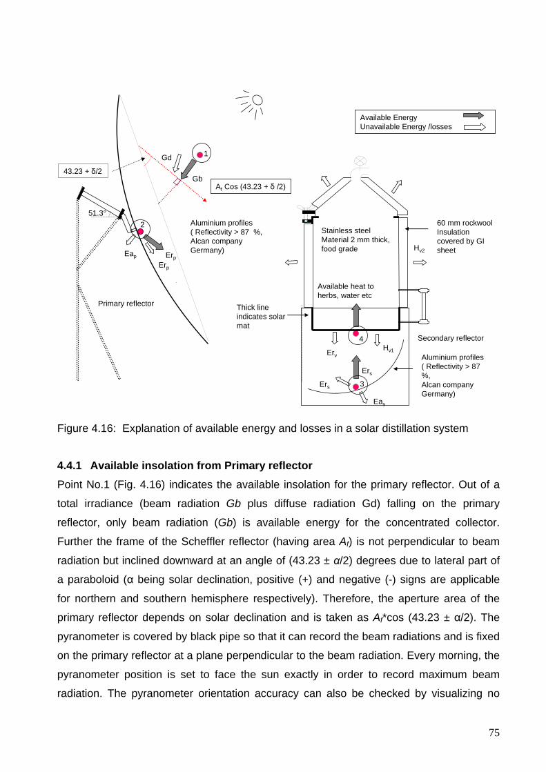
75
Af Cos (43.23 + δ /2)
ErpErp
Gd
Eap
Eas
Ers
Ers
ErvHv1
Hv2
Available heat to herbs, water etc
Gb43.23 + δ/2
Available Energy Unavailable Energy /losses
Primary reflector
Secondary reflector
60 mm rockwool Insulation covered by GI sheet
Thick line indicates solar mat
Aluminium profiles( Reflectivity > 87 %,Alcan company Germany)
Stainless steel Material 2 mm thick, food grade
1
2
3
4
Aluminium profiles( Reflectivity > 87 %,Alcan company Germany)
51.3°
Figure 4.16: Explanation of available energy and losses in a solar distillation system
4.4.1 Available insolation from Primary reflector Point No.1 (Fig. 4.16) indicates the available insolation for the primary reflector. Out of a
total irradiance (beam radiation Gb plus diffuse radiation Gd) falling on the primary
reflector, only beam radiation (Gb) is available energy for the concentrated collector.
Further the frame of the Scheffler reflector (having area Af) is not perpendicular to beam
radiation but inclined downward at an angle of (43.23 ± α/2) degrees due to lateral part of
a paraboloid (α being solar declination, positive (+) and negative (-) signs are applicable
for northern and southern hemisphere respectively). Therefore, the aperture area of the
primary reflector depends on solar declination and is taken as Af*cos (43.23 ± α/2). The
pyranometer is covered by black pipe so that it can record the beam radiations and is fixed
on the primary reflector at a plane perpendicular to the beam radiation. Every morning, the
pyranometer position is set to face the sun exactly in order to record maximum beam
radiation. The pyranometer orientation accuracy can also be checked by visualizing no
76
shadow all around the pyranometer during the whole day. In this way, the total input
energy available (Ep) at the reflector face is the beam radiation recorded by pyranometer
times this fraction of the area Af*cos (43.23 ± α/2) and is given in the mathematical form:
⎟⎠⎞
⎜⎝⎛ ±==
22343 α.cosAGE fbp (4.28)
Also
⎟⎠⎞
⎜⎝⎛ ±=
22343 α.cosAA fs (4.29)
where As is the available aperture area of the Scheffler reflector at any day of the year
As the primary reflector is elliptical in shape, the surface area can also be expressed in
semi-minor axis and semi-major axis. Eq. (4.28) can also be expressed as:
( ) ⎟⎠⎞
⎜⎝⎛ ±−=
2234310 απ .cos.baAs (4.30)
where a is the semi-minor axis of the elliptical frame of Scheffler reflector, b is the semi-
major axis of the elliptical frame of the Scheffler reflector, α is the solar declination.
The semi-major axis and semi-minor axis for the elliptical frame of the Scheffler reflector
are 1.88 and 1.37 m respectively. The area of the ellipse is reduced by 0.1 m2 to allow the
installation of different devices like the photovoltaic daily tracking device and the
pyranometer. Equation quoted by Duffie & Beckman, (2006) with the least error (Error <
0.035°) is used for calculation of solar declination.
( ) ( )[ ]( ) ( ) ( )
( ) 365213001480365213002679036521200090703652120067580
3652107025703652139991200069180180
ππππ
πππα
−−−−+−−
−+−−=
nsin.ncos.nsin.ncos.
nsin.)n(cos..
(4.31)
Solar declination “α” varies from -23.5° to +23.5° from December 21 to June 21. The
variation of solar declination and aperture area for standing reflectors in the northern and
southern hemispheres during the entire year is shown in Fig. 4.17 and also given in
Appendix B in tabular form (for performance evaluation calculations).

77
Days of the year, n
0 100 200 300
Sola
r dec
linat
ion,
deg
rees
-30
-20
-10
0
10
20
30
Aper
ture
are
a, m
2
0
2
4
6
8
Solar declination
Apertue area-(southern hemisphere)
Aperture area(northern hemisphere)
Figure 4.17: Variation of solar declination and aperture area of Scheffler reflector in the northern and southern hemisphere (valid for standings reflectors)
It is evident from figure 4.17 that aperture area is maximum (6.4 m2) on December 21 and
minimum (4.59 m2) on June 21 in the northern hemisphere for the standing reflectors. On
the other hand, the aperture area is minimum (4.59 m2) on December 21 and maximum on
June 21 (6.4 m2) for the standing reflectors in the southern hemisphere. It is also evident
from the figure that standing reflectors have the same aperture area (5.83 m2) at equinox.
For a given Scheffler reflector, more energy can be obtained from the standing reflectors
designs in winter seasons as compared with the summer seasons at the same intensity of
beam radiation. These reflectors are more suitable in tropical countries to maintain uniform
power output throughout the year. The standing reflectors also provide an excellent
opportunity to have the fixed focus well near the ground level. The variation of solar
declination and aperture area for the laying reflectors in the northern and southern
hemispheres during the entire year is shown in Fig. 4.18 and also given in Appendix B in
the tabular form (for performance evaluation calculations)
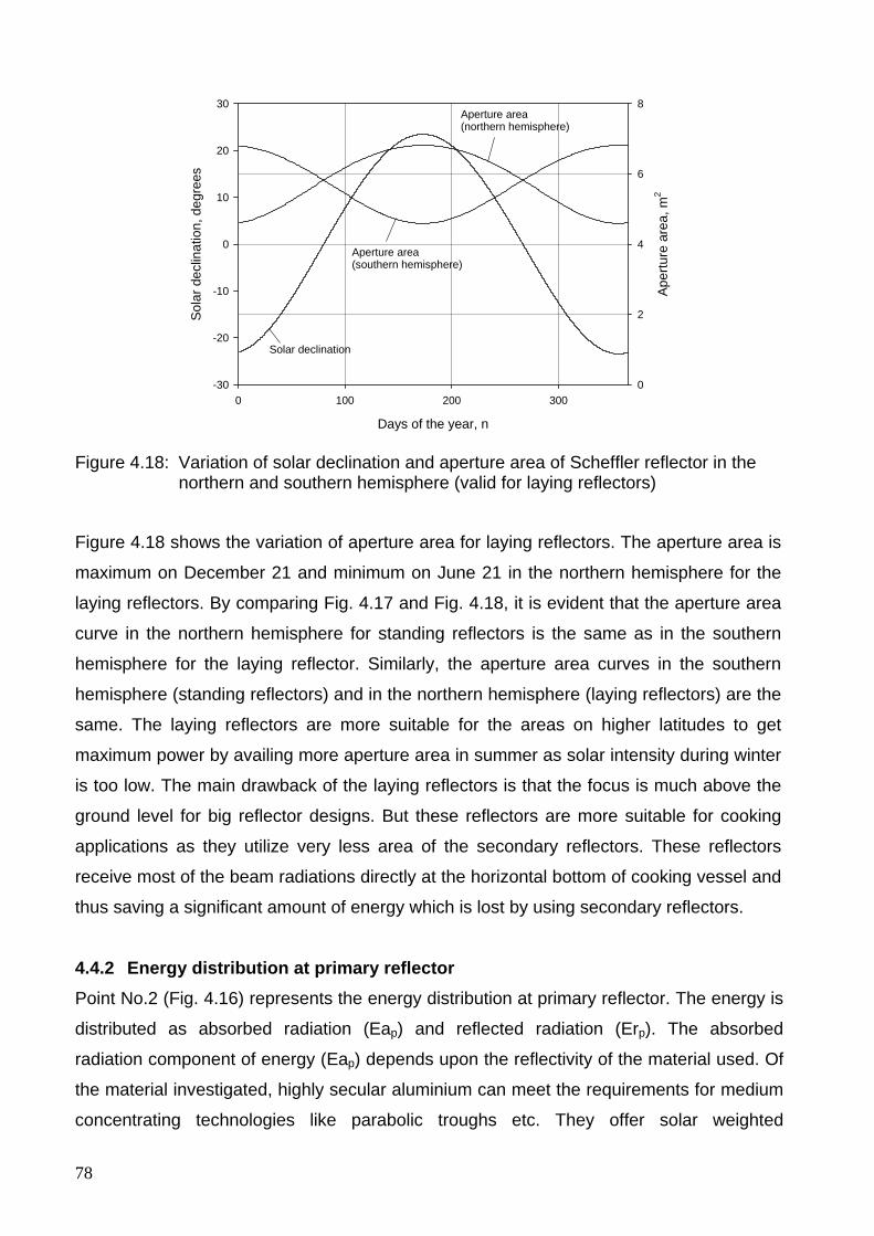
78
Days of the year, n
0 100 200 300
Sola
r dec
linat
ion,
deg
rees
-30
-20
-10
0
10
20
30
Aper
ture
are
a, m
2
0
2
4
6
8
Aperture area(southern hemisphere)
Aperture area(northern hemisphere)
Solar declination
Figure 4.18: Variation of solar declination and aperture area of Scheffler reflector in the northern and southern hemisphere (valid for laying reflectors)
Figure 4.18 shows the variation of aperture area for laying reflectors. The aperture area is
maximum on December 21 and minimum on June 21 in the northern hemisphere for the
laying reflectors. By comparing Fig. 4.17 and Fig. 4.18, it is evident that the aperture area
curve in the northern hemisphere for standing reflectors is the same as in the southern
hemisphere for the laying reflector. Similarly, the aperture area curves in the southern
hemisphere (standing reflectors) and in the northern hemisphere (laying reflectors) are the
same. The laying reflectors are more suitable for the areas on higher latitudes to get
maximum power by availing more aperture area in summer as solar intensity during winter
is too low. The main drawback of the laying reflectors is that the focus is much above the
ground level for big reflector designs. But these reflectors are more suitable for cooking
applications as they utilize very less area of the secondary reflectors. These reflectors
receive most of the beam radiations directly at the horizontal bottom of cooking vessel and
thus saving a significant amount of energy which is lost by using secondary reflectors.
4.4.2 Energy distribution at primary reflector Point No.2 (Fig. 4.16) represents the energy distribution at primary reflector. The energy is
distributed as absorbed radiation (Eap) and reflected radiation (Erp). The absorbed
radiation component of energy (Eap) depends upon the reflectivity of the material used. Of
the material investigated, highly secular aluminium can meet the requirements for medium
concentrating technologies like parabolic troughs etc. They offer solar weighted
79
reflectance of 88–91 %, good mechanical properties and are easy to recycle (Fend et al.,
2000). Aluminium profiles from Alcan Company, Germany were used with reflectivity
greater than 87 %. The energy available after primary reflector (Epr) is given as:
pppr ERE = (4.32)
where Rp is the reflectivity of the material used for the primary reflector
Some of the radiations are reflected from the primary reflector out of the focus. This
deviation is due to the improper reflector profiles and inadequacy in daily and seasonal
tracking. The accuracy of the profiles was checked with the help of a special jig designed
for this purpose. Infrared camera was also used to measure the fraction of available
radiations at targeted focus and out of the focus. It was found that about 12-18 %
radiations are not falling on the target and are unavailable for the secondary reflector to
further utilize it. The fraction available at the targeted focus (Ff) in general calculation is
taken as 0.85. The energy available at the secondary reflector (Es) is given as:
fprs FEE = (4.33)
4.4.3 Energy distribution at secondary reflector Point No.3 (Fig. 4.16) indicates the available energy and losses at secondary reflector.
Precisely curved and high reflectivity aluminium sheets (reflectance > 87) were used to
reduce the losses. The energy available after secondary reflection (Esr) is given as:
sssr REE =
where Rs is the reflectivity of the secondary reflector (0.87 for aluminium sheets)
A concrete foundation bed was constructed to fix the secondary reflector at optimum
position with respect to calculated focal point as detailed in Fig. 3.2. Aluminium profiles of
secondary reflector are designed to reflect and distribute all the beam radiations on the
bottom of distillation unit. The energy available at the distillation bottom (Ev) is given as:
vsrv FEE = (4.34)
where Fv is the fraction of energy available at the distillation bottom
80
4.4.4 Energy losses from the distillation unit Point No.4 (Fig. 4.16) indicates the energy losses from vessel (distillation unit). These
losses include reflectivity due to incomplete absorbance (Erv) and heat losses from
different parts of the vessel i.e., through conduction, convection and radiation. The thermal
performance of the absorber is enhanced by a selective coating with high absorptivity in
the solar spectrum and low emissivity in the infrared radiation band associated with the
operating temperature. The bottom part and 120 mm part of the side of the distillation still
remain inside the secondary reflector and are exposed to reflected solar radiations. A heat
resistant black paint (Schwarz Matt, RAL 9011) was applied to absorb maximum radiations
falling on it. Prior to application, the bottom part of the distillation still was made rough with
emery paper to maximize the adhesion of the paint. The heat energy available to run the
distillation system (Eab) is given as:
vvab AEE =
where Av is the absorbance of the vessel
Other losses at point No.4 (Fig. 4.16) are due to convection and radiation losses from the
vessel. Hv1 and Hv2 are the total heat losses from the area exposed to solar radiations
(bottom and 120 mm of adjacent lateral) and area not exposed to solar radiations (lateral
and top) respectively as shown in Fig. 4.16.
The thermal losses calculations are carried out under the existing sizes and conditions of
the distillation unit. These calculations also provide decision making to calculate the
appropriate lagging thickness. The insulation thickness is taken as a variable parameter
during the calculations. The calculation of the thermal losses of the distillation unit is done
by taking into account the three thermal heat transfer modes i.e., conduction, convection
and radiations. The conduction heat transfer is considered through the stainless steel wall,
rockwool insulation, and the galvanized iron sheet. Depending upon the heat energy
utilization and geometric consideration, the distillation still is divided into the following three
main parts:
1. Lateral part of the distillation still (not exposed to solar radiation and can be
insulated to reduce heat losses)
2. Part exposed to solar radiation (bottom and adjacent lateral part)
81
3. Top cover (conical part and lateral part to sit on the seat, the conical part was
insulated and the lateral part was not insulated as it is a junction to tight the two
parts of the still)
The heat losses are calculated for different parts of the still and are programmed in a
Matlab 7 and Microsoft Excel spreadsheet. Thereafter, losses are calculated at different
insulation thicknesses to select the combination which is economically feasible and easy to
handle. The model is developed in general form to apply for different sizes of the
distillation still. Here, the losses are calculated for the given solar distillation prototype.
For most of the distillation experiments, the operating temperature was taken as 100 °C.
The steam contacting the plant material is at 100 °C which is acceptable for most plant
material and this temperature remain constant for the duration of the distillation (Dürbeck,
1997).
Following assumptions are made for the modeling of solar distillation system
• The ambient temperature (Tamb) is taken as 20 °C because most of the experiments
were conducted at this temperature.
• The space temperature (Tspace) is necessary to calculate the radiative losses and is
taken as 15 °C by considering that the environment reacts like a black body.
• The thermal contact resistively between different layers of the insulation is
neglected.
• Beam radiations are distributed on the bottom of the distillation still after reflection
from the secondary reflector.
4.5 Thermal losses calculation of the distillation still 4.5.1 Conduction and convection losses The steady state heat transfer (φ) through a cylindrical layer that are exposed to
convection on both sides to fluids is given as (Cengel, 2006):
convcond
ambin
RRTT+−
=ϕ (4.35)
where Tin is the temperature inside the distillation still, Tamb is the ambient temperature,
Rcond is the conduction resistance, Rconv is the convection resistance
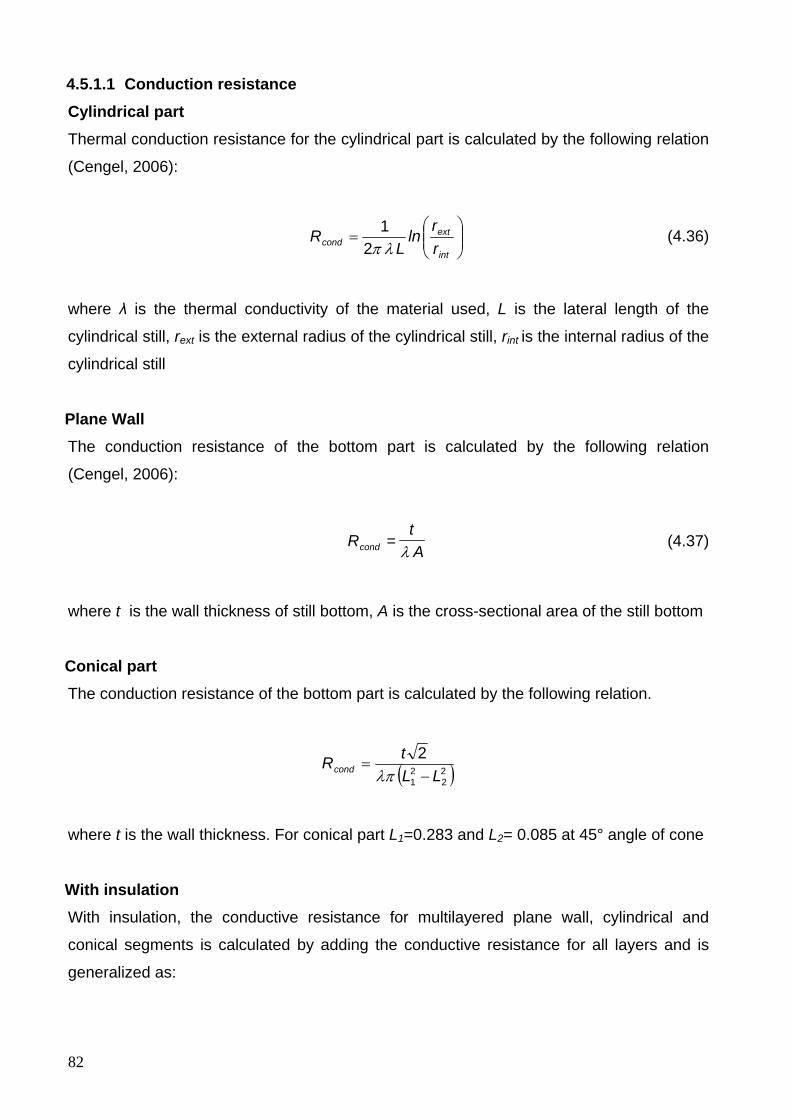
82
4.5.1.1 Conduction resistance Cylindrical part Thermal conduction resistance for the cylindrical part is calculated by the following relation
(Cengel, 2006):
⎟⎟⎠
⎞⎜⎜⎝
⎛=
int
extcond r
rln
LR
λπ21 (4.36)
where λ is the thermal conductivity of the material used, L is the lateral length of the
cylindrical still, rext is the external radius of the cylindrical still, rint is the internal radius of the
cylindrical still
Plane Wall The conduction resistance of the bottom part is calculated by the following relation
(Cengel, 2006):
At
Rcond λ= (4.37)
where t is the wall thickness of still bottom, A is the cross-sectional area of the still bottom
Conical part The conduction resistance of the bottom part is calculated by the following relation.
( )22
21
2LL
tRcond −=λπ
where t is the wall thickness. For conical part L1=0.283 and L2= 0.085 at 45° angle of cone
With insulation With insulation, the conductive resistance for multilayered plane wall, cylindrical and
conical segments is calculated by adding the conductive resistance for all layers and is
generalized as:
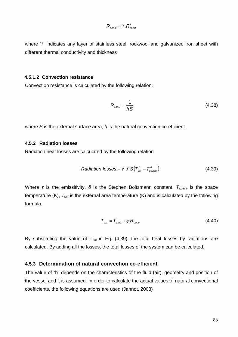
83
icondcond RR ∑=
where “i" indicates any layer of stainless steel, rockwool and galvanized iron sheet with
different thermal conductivity and thickness
4.5.1.2 Convection resistance Convection resistance is calculated by the following relation.
Sh
Rconv1
= (4.38)
where S is the external surface area, h is the natural convection co-efficient.
4.5.2 Radiation losses Radiation heat losses are calculated by the following relation
( )44spaceext TTSlossesRadiation −= δε (4.39)
Where ε is the emissitivity, δ is the Stephen Boltzmann constant, Tspace is the space
temperature (K), Text is the external area temperature (K) and is calculated by the following
formula.
convambext RTT ϕ+= (4.40)
By substituting the value of Text in Eq. (4.39), the total heat losses by radiations are
calculated. By adding all the losses, the total losses of the system can be calculated.
4.5.3 Determination of natural convection co-efficient The value of “h” depends on the characteristics of the fluid (air), geometry and position of
the vessel and it is assumed. In order to calculate the actual values of natural convectional
coefficients, the following equations are used (Jannot, 2003)
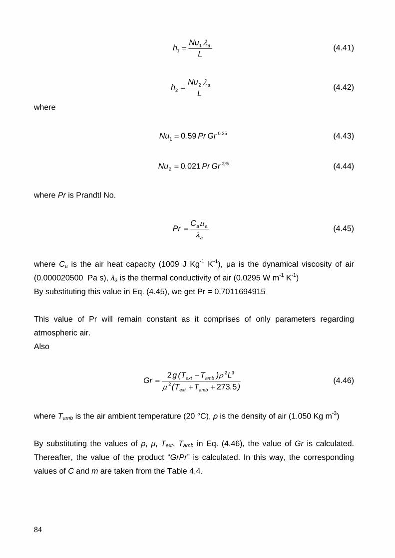
84
L
Nuh aλ1
1 = (4.41)
L
Nuh aλ2
2 = (4.42)
where
2501 590 .GrPr.Nu = (4.43)
522 0210 GrPr.Nu = (4.44)
where Pr is Prandtl No.
a
aaCPr
λμ
= (4.45)
where Ca is the air heat capacity (1009 J Kg-1 K-1), μa is the dynamical viscosity of air
(0.000020500 Pa s), λa is the thermal conductivity of air (0.0295 W m-1 K-1)
By substituting this value in Eq. (4.45), we get Pr = 0.7011694915
This value of Pr will remain constant as it comprises of only parameters regarding
atmospheric air.
Also
).TT(
L)TT(gGr
ambext
ambext
527322
32
++−
=μ
ρ (4.46)
where Tamb is the air ambient temperature (20 °C), ρ is the density of air (1.050 Kg m-3)
By substituting the values of ρ, μ, Text, Tamb in Eq. (4.46), the value of Gr is calculated.
Thereafter, the value of the product “GrPr” is calculated. In this way, the corresponding
values of C and m are taken from the Table 4.4.
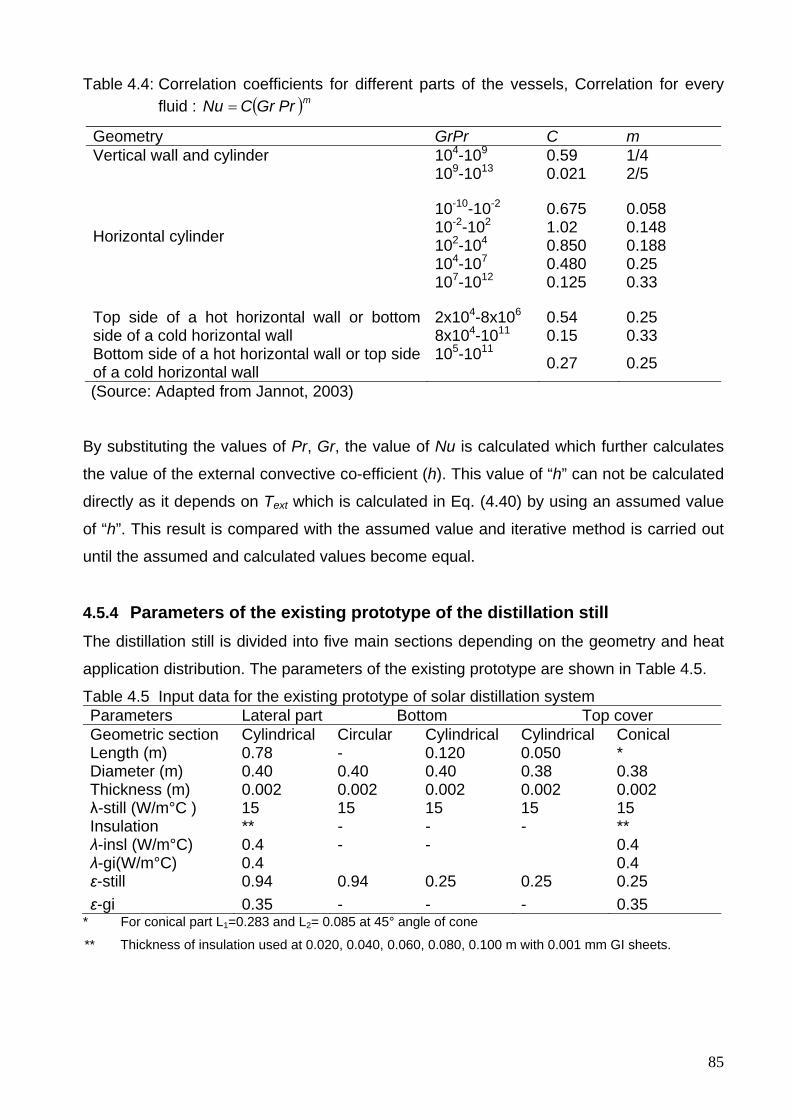
85
Table 4.4: Correlation coefficients for different parts of the vessels, Correlation for every fluid : ( )mPrGrCNu =
Geometry GrPr C m Vertical wall and cylinder
104-109 109-1013
0.59 0.021
1/4 2/5
Horizontal cylinder
10-10-10-2 10-2-102 102-104 104-107 107-1012
0.675 1.02 0.850 0.480 0.125
0.058 0.148 0.188 0.25 0.33
Top side of a hot horizontal wall or bottom side of a cold horizontal wall
2x10⁴-8x10⁶ 8x10⁴-1011
0.54 0.15
0.25 0.33
Bottom side of a hot horizontal wall or top side of a cold horizontal wall
105-1011 0.27 0.25
(Source: Adapted from Jannot, 2003)
By substituting the values of Pr, Gr, the value of Nu is calculated which further calculates
the value of the external convective co-efficient (h). This value of “h” can not be calculated
directly as it depends on Text which is calculated in Eq. (4.40) by using an assumed value
of “h”. This result is compared with the assumed value and iterative method is carried out
until the assumed and calculated values become equal.
4.5.4 Parameters of the existing prototype of the distillation still The distillation still is divided into five main sections depending on the geometry and heat
application distribution. The parameters of the existing prototype are shown in Table 4.5.
Table 4.5 Input data for the existing prototype of solar distillation system Parameters Lateral part Bottom Top cover Geometric section Cylindrical Circular Cylindrical Cylindrical Conical Length (m) 0.78 - 0.120 0.050 * Diameter (m) 0.40 0.40 0.40 0.38 0.38 Thickness (m) 0.002 0.002 0.002 0.002 0.002 λ-still (W/m°C ) 15 15 15 15 15 Insulation ** - - - ** λ-insl (W/m°C) 0.4 - - 0.4 λ-gi(W/m°C) 0.4 0.4 ε-still 0.94 0.94 0.25 0.25 0.25 ε-gi 0.35 - - - 0.35
* For conical part L1=0.283 and L2= 0.085 at 45° angle of cone
** Thickness of insulation used at 0.020, 0.040, 0.060, 0.080, 0.100 m with 0.001 mm GI sheets.
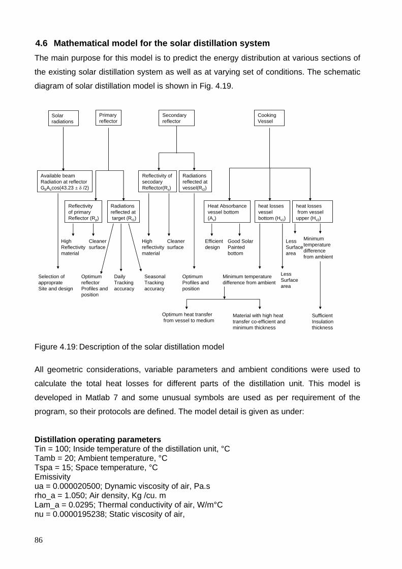
86
4.6 Mathematical model for the solar distillation system The main purpose for this model is to predict the energy distribution at various sections of
the existing solar distillation system as well as at varying set of conditions. The schematic
diagram of solar distillation model is shown in Fig. 4.19.
Solar radiations
Primary reflector
Secondary reflector
Cooking Vessel
Available beam Radiation at reflectorGbAscos(43.23 ± δ /2)
Reflectivityof primaryReflector (Rp)
Radiations reflected attarget (Rt1)
Reflectivity of secodaryReflector(Rs)
Radiationsreflected at vessel(Rt2)
Heat Absorbancevessel bottom(Av)
heat losses vessel bottom (Hv1)
heat lossesfrom vessel
upper (Hv2)
High Reflectivitymaterial
Cleaner surface
Optimum reflectorProfiles and position
Daily Trackingaccuracy
Seasonal Trackingaccuracy
Highreflectivitymaterial
Cleaner surface
Optimum Profiles andposition
Good Solar Paintedbottom
Efficient design
LessSurfacearea
LessSurface area
Minimum temperature difference from ambient
Selection of approprate Site and design
Minimum temperature difference from ambient
Material with high heat transfer co-efficient and minimum thickness
SufficientInsulation thickness
Optimum heat transferfrom vessel to medium
Figure 4.19: Description of the solar distillation model All geometric considerations, variable parameters and ambient conditions were used to
calculate the total heat losses for different parts of the distillation unit. This model is
developed in Matlab 7 and some unusual symbols are used as per requirement of the
program, so their protocols are defined. The model detail is given as under:
Distillation operating parameters Tin = 100; Inside temperature of the distillation unit, °C Tamb = 20; Ambient temperature, °C Tspa = 15; Space temperature, °C Emissivity ua = 0.000020500; Dynamic viscosity of air, Pa.s rho_a = 1.050; Air density, Kg /cu. m Lam_a = 0.0295; Thermal conductivity of air, W/m°C nu = 0.0000195238; Static viscosity of air,
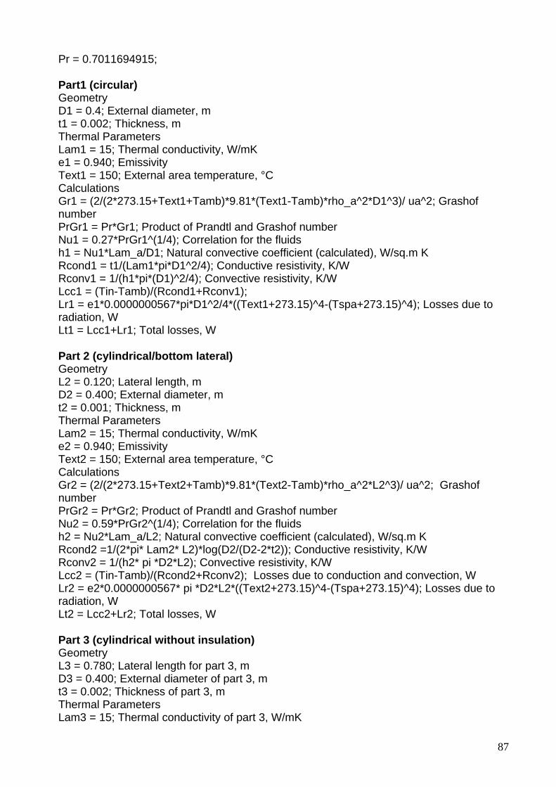
87
Pr = 0.7011694915; Part1 (circular) Geometry D1 = 0.4; External diameter, m t1 = 0.002; Thickness, m Thermal Parameters Lam1 = 15; Thermal conductivity, W/mK e1 = 0.940; Emissivity Text1 = 150; External area temperature, °C Calculations Gr1 = (2/(2*273.15+Text1+Tamb)*9.81*(Text1-Tamb)*rho_a^2*D1^3)/ ua^2; Grashof number PrGr1 = Pr*Gr1; Product of Prandtl and Grashof number Nu1 = 0.27*PrGr1^(1/4); Correlation for the fluids h1 = Nu1*Lam_a/D1; Natural convective coefficient (calculated), W/sq.m K Rcond1 = t1/(Lam1*pi*D1^2/4); Conductive resistivity, K/W Rconv1 = 1/(h1*pi*(D1)^2/4); Convective resistivity, K/W Lcc1 = (Tin-Tamb)/(Rcond1+Rconv1); Lr1 = e1*0.0000000567*pi*D1^2/4*((Text1+273.15)^4-(Tspa+273.15)^4); Losses due to radiation, W Lt1 = Lcc1+Lr1; Total losses, W Part 2 (cylindrical/bottom lateral) Geometry L2 = 0.120; Lateral length, m D2 = 0.400; External diameter, m t2 = 0.001; Thickness, m Thermal Parameters Lam2 = 15; Thermal conductivity, W/mK e2 = 0.940; Emissivity Text2 = 150; External area temperature, °C Calculations Gr2 = (2/(2*273.15+Text2+Tamb)*9.81*(Text2-Tamb)*rho_a^2*L2^3)/ ua^2; Grashof number PrGr2 = Pr*Gr2; Product of Prandtl and Grashof number Nu2 = 0.59*PrGr2^(1/4); Correlation for the fluids h2 = Nu2*Lam_a/L2; Natural convective coefficient (calculated), W/sq.m K Rcond2 =1/(2*pi* Lam2* L2)*log(D2/(D2-2*t2)); Conductive resistivity, K/W Rconv2 = 1/(h2* pi *D2*L2); Convective resistivity, K/W Lcc2 = (Tin-Tamb)/(Rcond2+Rconv2); Losses due to conduction and convection, W Lr2 = e2*0.0000000567* pi *D2*L2*((Text2+273.15)^4-(Tspa+273.15)^4); Losses due to radiation, W Lt2 = Lcc2+Lr2; Total losses, W Part 3 (cylindrical without insulation) Geometry L3 = 0.780; Lateral length for part 3, m D3 = 0.400; External diameter of part 3, m t3 = 0.002; Thickness of part 3, m Thermal Parameters Lam3 = 15; Thermal conductivity of part 3, W/mK
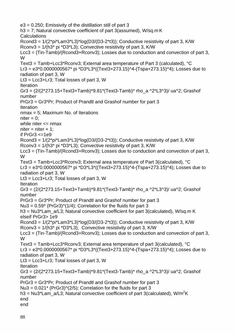
88
e3 = 0.250; Emissivity of the distillation still of part 3 h3 = 7; Natural convective coefficient of part 3(assumed), W/sq.m K Calculations Rcond3 = 1/(2*pi*Lam3*L3)*log(D3/(D3-2*t3)); Conductive resistivity of part 3, K/W Rconv3 = 1/(h3* pi *D3*L3); Convective resistivity of part 3, K/W Lcc3 = (Tin-Tamb)/(Rcond3+Rconv3); Losses due to conduction and convection of part 3, W Text3 = Tamb+Lcc3*Rconv3; External area temperature of Part 3 (calculated), °C Lr3 = e3*0.0000000567* pi *D3*L3*((Text3+273.15)^4-(Tspa+273.15)^4); Losses due to radiation of part 3, W Lt3 = Lcc3+Lr3; Total losses of part 3, W Iteration Gr3 = (2/(2*273.15+Text3+Tamb)*9.81*(Text3-Tamb)* rho_a ^2*L3^3)/ ua^2; Grashof number PrGr3 = Gr3*Pr; Product of Prandtl and Grashof number for part 3 Iteration nmax = 5; Maximum No. of Iterations niter = 0; while niter <= nmax niter = niter + 1; if PrGr3 <=1e9 Rcond3 = 1/(2*pi*Lam3*L3)*log(D3/(D3-2*t3)); Conductive resistivity of part 3, K/W Rconv3 = 1/(h3* pi *D3*L3); Convective resistivity of part 3, K/W Lcc3 = (Tin-Tamb)/(Rcond3+Rconv3); Losses due to conduction and convection of part 3, W Text3 = Tamb+Lcc3*Rconv3; External area temperature of Part 3(calculated), °C Lr3 = e3*0.0000000567* pi *D3*L3*((Text3+273.15)^4-(Tspa+273.15)^4); Losses due to radiation of part 3, W Lt3 = Lcc3+Lr3; Total losses of part 3, W Iteration Gr3 = (2/(2*273.15+Text3+Tamb)*9.81*(Text3-Tamb)* rho_a ^2*L3^3)/ ua^2; Grashof number PrGr3 = Gr3*Pr; Product of Prandtl and Grashof number for part 3 Nu3 = 0.59* (PrGr3)^(1/4); Correlation for the fluids for part 3 h3 = Nu3*Lam_a/L3; Natural convective coefficient for part 3(calculated), W/sq.m K elseif PrGr3> 1e9 Rcond3 = 1/(2*pi*Lam3*L3)*log(D3/(D3-2*t3)); Conductive resistivity of part 3, K/W Rconv3 = 1/(h3* pi *D3*L3); Convective resistivity of part 3, K/W Lcc3 = (Tin-Tamb)/(Rcond3+Rconv3); Losses due to conduction and convection of part 3, W Text3 = Tamb+Lcc3*Rconv3; External area temperature of part 3(calculated), °C Lr3 = e3*0.0000000567* pi *D3*L3*((Text3+273.15)^4-(Tspa+273.15)^4); Losses due to radiation of part 3, W Lt3 = Lcc3+Lr3; Total losses of part 3, W Iteration Gr3 = (2/(2*273.15+Text3+Tamb)*9.81*(Text3-Tamb)* rho_a ^2*L3^3)/ ua^2; Grashof number PrGr3 = Gr3*Pr; Product of Prandtl and Grashof number for part 3 Nu3 = 0.021* (PrGr3)^(2/5); Correlation for the fluids for part 3 h3 = Nu3*Lam_a/L3; Natural convective coefficient of part 3(calculated), W/m2K end end
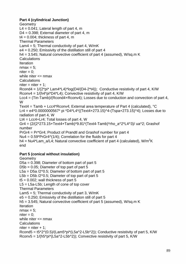
89
Part 4 (cylindrical Junction) Geometry L4 = 0.041; Lateral length of part 4, m D4 = 0.398; External diameter of part 4, m t4 = 0.004; thickness of part 4, m Thermal Parameters Lam4 = 5; Thermal conductivity of part 4, W/mK e4 = 0.250; Emissivity of the distillation still of part 4 h4 = 3.545; Natural convective coefficient of part 4 (assumed), W/sq.m K Calculations Iteration nmax = 5; niter = 0; while niter <= nmax Calculations niter = niter + 1; Rcond4 = 1/(2*pi* Lam4*L4)*log(D4/(D4-2*t4)); Conductive resistivity of part 4, K/W Rconv4 = 1/(h4*pi*D4*L4); Convective resistivity of part 4, K/W Lcc4 = (Tin-Tamb)/(Rcond4+Rconv4); Losses due to conduction and convection of part 4, W Text4 = Tamb + Lcc4*Rconv4; External area temperature of Part 4 (calculated), °C Lr4 = e4*0.0000000567* pi *D4*L4*((Text4+273.15)^4-(Tspa+273.15)^4); Losses due to radiation of part 4, W Lt4 = Lcc4+Lr4; Total losses of part 4, W Gr4 = (2/(2*273.15+Text4+Tamb)*9.81*(Text4-Tamb)*rho_a^2*L4^3)/ ua^2; Grashof number PrGr4 = Pr*Gr4; Product of Prandtl and Grashof number for part 4 Nu4 = 0.59*PrGr4^(1/4); Correlation for the fluids for part 4 h4 = Nu4*Lam_a/L4; Natural convective coefficient of part 4 (calculated), W/m2K end Part 5 (conical without insulation) Geometry D5a = 0.398; Diameter of bottom part of part 5 D5b = 0.05; Diameter of top part of part 5 L5a = D5a /2^0.5; Diameter of bottom part of part 5 L5b = D5b /2^0.5; Diameter of top part of part 5 t5 = 0.002; wall thickness of part 5 L5 = L5a-L5b; Length of cone of top cover Thermal Parameters Lam5 = 5; Thermal conductivity of part 3, W/mK e5 = 0.250; Emissivity of the distillation still of part 5 h5 = 3.545; Natural convective coefficient of part 5 (assumed), W/sq.m K Iteration nmax = 5; niter = 0; while niter <= nmax Calculations niter = niter + 1; Rcond5 = t5*2^(0.5)/(Lam5*pi*(L5a^2-L5b^2)); Conductive resistivity of part 5, K/W Rconv5 = 1/(h5*pi*(L5a^2-L5b^2)); Convective resistivity of part 5, K/W
90
Lcc5 = (Tin-Tamb)/(Rcond5+Rconv5); Losses due to conduction and convection of part 5, W Text5 = Tamb+Lcc5*Rconv5;% External area temperature of part 3(calculated), °C Lr5 = e5*0.0000000567*pi*(L5a^2-L5b^2)*((Text5+273.15)^4-(Tspa+273.15)^4); Losses due to radiation of part 5, W Lt5 = Lcc5+Lr5; Total losses of part 5, W Gr5 = (2/(2*273.15+Text5+Tamb)*9.81*(Text5-Tamb)*rho_a^2*L5^3)/ua^2; Grashof number PrGr5 = Pr*Gr5; Product of Prandtl and Grashof number for part 5 Nu5 = 0.59*PrGr5^(1/4); Correlation for the fluids for part 5 h5 = Nu5*Lam_a/L5; Natural convective coefficient of part 5(calculated), W/sq.m K end Part 3 (cylindrical with insulation) Geometry L3 = 0.780; lateral length of insulated still, m D3 = 0.400; External diameter of still for part 3 to be insulated, m t3 = 0.002; Wall Thickness of the still of part 3 to be insulated, m for tt = 0.02:0.02:0.1; t3ins = tt; Insulation thickness used for part 3, m t3gi = .001; Thermal Parameters Lam3 = 15; Thermal conductivity of the still for part 3 to be insulated, W/mK Lamins = 0.040; Thermal conductivity of insulation for part 3, W/mK Lamgi = 0.040; Thermal conductivity of galvanized iron sheet for part 3, W/mK egi = 0.350; Emissivity of the Galvanized iron sheet for part 3 hgi3 = 13.545; Natural convective coefficient for galvanized iron part 3 (assumed), W/m2K Iteration nmax = 5; niter = 0; while niter <= nmax Calculations niter = niter + 1; Rcond3ins = 1/(2*pi*Lamins*L3)*log((D3+2*t3ins)/D3); Conductive resistivity of insulated part 3, K/W Rcond3gi = 1/(2*pi*Lamgi*L3)* log((D3+2*t3ins+2*t3gi)/(D3+2*t3ins)); Conductive resistivity of insulated part 3, K/W Rconv3gi = 1/(hgi3*pi*(D3+2*t3ins+2*t3gi)*L3); Convective resistivity of insulated part 3, K/W Lcc3ins = (Tin-Tamb)/(Rcond3+ Rcond3ins+ Rcond3gi+ Rconv3gi); Losses due to conduction and convection of part 3, W Text3ins = Tamb+Lcc3ins*Rconv3gi; External area temperature of gi sheet with part 3 Lr3ins = egi*0.0000000567*pi*(D3+2*t3ins+2*t3gi)*L3*((Text3ins+273.15)^4 ... -(Tspa+273.15)^4); Losses due to radiation of insulated part 3, W Lt3ins = Lcc3ins+Lr3ins; Total losses of insulated part 3, W Gr3ins = (2/(2*273.15+Text3ins+Tamb)*9.81*(Text3ins-Tamb)* rho_a ^2*L3^3)/ ua^2; Grashof number for insulated part 3 PrGr3ins = Pr*Gr3ins; Product of Prandtl and Grashof number for insulated part 3 Nu3ins = 0.59*PrGr3ins^(1/4); Correlation for the fluids for part 3 hgi3 = Nu3ins*Lam_a/L3; Natural convective coefficient of insulated part 3(calculated), W/m2K end
91
Part 5 (Conical with insulation) Geometry D5a = 0.398; Diameter of bottom part of part 5 to be insulated D5b = 0.05; Diameter of top part of part 5 to be insulated L5a = D5a /2^0.5; Diameter of bottom part of part 5 to be insulated L5b = D5b /2^0.5; Diameter of top part of part 5 to be insulated t5 = 0.002; t5ins = tt; t5gi = 0.001; Thermal Parameters Lam5 = 15; Thermal conductivity of insulated part 5, W/mK Lam5ins = 0.040; Thermal conductivity insulation for part 5, W/mK Lam5gi = 0.040; Thermal conductivity of gi sheet for part 5, W/mK e5gi = 0.350; Emissivity of the GI sheet part 5 h5gi = 3.545; Natural convective coefficient of part 5 insulated (assumed), W/m2K Iteration nmax = 5; niter = 0; while niter <= nmax Calculations niter = niter + 1; Rcond5 = t5*2^(0.5)/(Lam5*pi*(L5a^2-L5b^2)); Conductive resistivity of part 5 insulated, K/W Rcond5ins = (t5ins*(2)^0.5)/(Lam5ins*pi*(L5a^2-L5b^2)); Conductive resistivity of insulated part 5 insulated, K/W Rcond5gi = (t5gi*(2)^0.5)/(Lam5gi*pi*(L5a^2-L5b^2)); Losses due to conduction and convection of part 5 insulated, W Rconv5gi = 1/(h5gi*pi*(L5a^2-L5b^2)); Convective resistivity of insulated part 5 insulated, K/W Lcc5ins = (Tin-Tamb)/(Rcond5+Rcond5ins+Rcond5gi+Rconv5gi); Text5ins = Tamb+Lcc5ins*Rconv5gi; External area temperature of Part 5 insulated (calculated), °C Lr5ins = pi*(L5a^2-L5b^2)*egi*0.0000000567*((Text5ins+273.15)^4-(Tspa+273.15)^4); Losses due to radiations of part 5 insulated, K/W Lt5ins = Lcc5ins+Lr5ins; Total losses of part 5 with insulation Gr5ins = (2/(2*273.15+Text5ins+Tamb)*9.81*(Text5ins-Tamb)*rho_a^2*L5^3)/ ua^2; Grashof number for insulated part 5 insulated PrGr5ins = Pr*Gr5ins; Product of Prandtl and Grashof number for insulated part 5 insulated Nu5ins = 0.59*PrGr5ins^(1/4); Correlation for the fluids for part 5 insulated h5gi = Nu5ins*Lam_a/L5; Natural convective coefficient of part 5(assumed), W/m2K Tgt = Lt1+Lt2+Lt3ins+Lt4+Lt5ins; Losses grand total with insulation end Complete Model (Solar distillation system) Gb = 800; Beam radiations, W m-2 Sp = 8.00; Surface area of primary reflector, m2 n = 100; No. of day of the year Rp = 0.87; Reflectivity of primary reflector Ff = 0.85; Fraction available at targeted focus Rs = 0.87; Reflectivity of secondary reflector Fv = 0.95; Fraction available at targeted vessel
92
Av = 0.90; Absorbance of vessel Lgt = Lt1+Lt2+Lt3ins+Lt4+Lt5ins; Grand total losses from vessel decl = 180/pi*(0.006918-0.399912*cos(2*pi/365*(n-1))... + 0.070257*sin(2*pi/365*(n-1))-0.006758*cos(2*(2*pi/365*(n-1)))... + 0.000907*sin(2*(2*pi/365*(n-1)))-0.002697*cos(3*(2*pi/365*(n-1)))... + 0.00148*sin(3*(2*pi/365*(n-1)))); Solar declination Energy distribution per unit time For standing reflectors in the northern hemisphere Ep1 = Gb*Sp*cosd(43.23+decl/2); Energy available at primary reflector, W Epr1 = Ep1*Rp; Energy available after primary reflection, W Es1 = Epr1*Ff; Energy available at secondary reflector, W Esr1 = Es1*Rs; Energy available after secondary reflection, W Ev1 = Esr1*Fv; Energy available at vessel surface, W Eab1 = Ev1*Av; Energy available inside the vessel, W Ed1 = Eab1-Lgt; Energy available for processing, W Eff1 = 100*Ed1/Ep1; Efficiency of solar distillation system, W For standing reflectors in the southern hemisphere decls = - decl; Ep2 = Gb*Sp*cosd(43.23+decls/2); Energy available at primary reflector, W Epr2 = Ep2*Rp; Energy available after primary reflection, W Es2 = Epr2*Ff; Energy available at secondary reflector, W Esr2 = Es2*Rs; Energy available after secondary reflection, W Ev2 = Esr2*Fv; Energy available at vessel surface, W Eab2 = Ev2*Av; Energy available inside the vessel, W Ed2 = Eab2-Lgt; Energy available for processing, W Eff2 = 100*Ed2/Ep2; Efficiency of solar distillation system, W Power Losses at different points For standing reflectors in the northern hemisphere Lpr1 = Ep1-Epr1; Losses due to reflectivity of primary reflector, W Lpf1 = Epr1-Es1; Losses due to focus not at target of primary reflector, W Lsr1 = Es1-Esr1; Losses due to reflectivity of secondary reflector, W Lsf1 = Esr1-Ev1; Losses due to focus not at target of secondary reflector, W Lab1 = Ev1-Eab1; Losses due to vessel heat absorption inefficiency, W Lgt1 = Lgt; Losses due to vessel heat losses For standing reflectors in the southern hemisphere Lpr2 = Ep2-Epr2; Losses due to reflectivity of primary reflector, W Lpf2 = Epr2-Es2; Losses due to focus not at target of primary reflector, W Lsr2 = Es2-Esr2; Losses due to reflectivity of secondary reflector, W Lsf2 = Esr2-Ev2; Losses due to focus not at target of secondary reflector, W Lab2 = Ev2-Eab2; Losses due to vessel heat absorption inefficiency, W Lgt2 = Lgt; end
The above mentioned model can be run on a specific day for the existing size of solar
distillation system under the site specific parameters of Witzenhausen, Germany,
(Latitude, 51.3°) by substituting the number of day of the year. The algorithm is developed
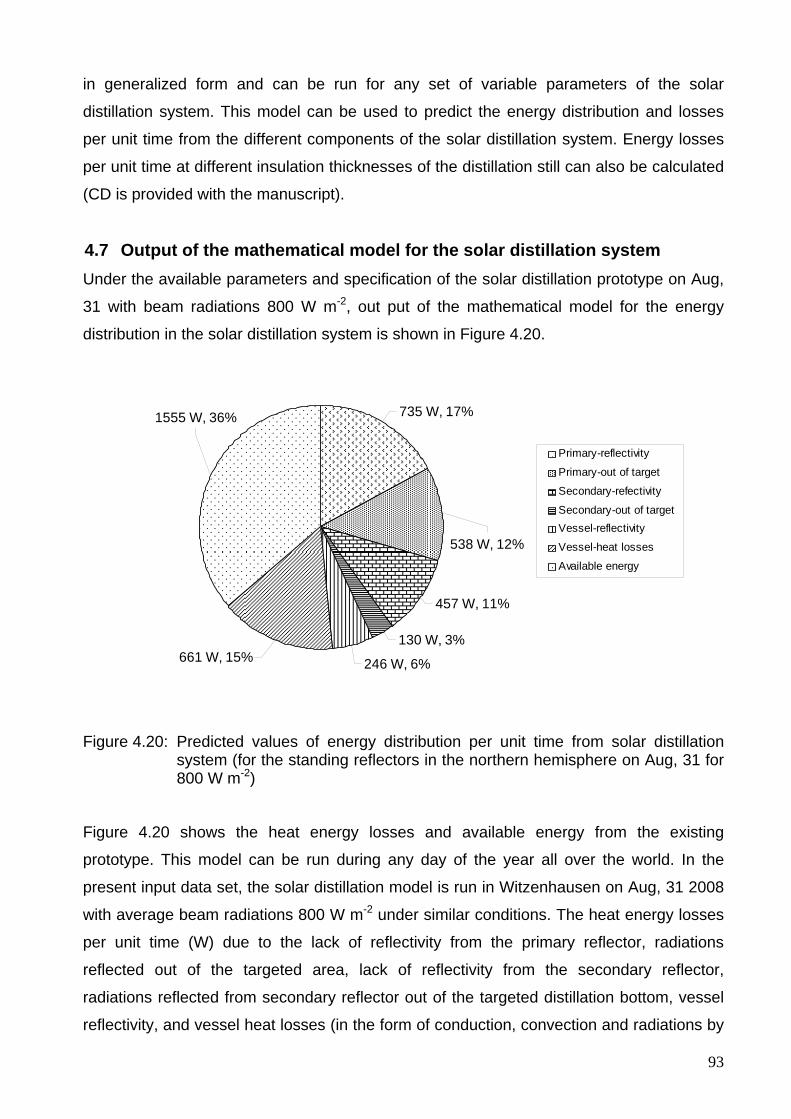
93
in generalized form and can be run for any set of variable parameters of the solar
distillation system. This model can be used to predict the energy distribution and losses
per unit time from the different components of the solar distillation system. Energy losses
per unit time at different insulation thicknesses of the distillation still can also be calculated
(CD is provided with the manuscript).
4.7 Output of the mathematical model for the solar distillation system Under the available parameters and specification of the solar distillation prototype on Aug,
31 with beam radiations 800 W m-2, out put of the mathematical model for the energy
distribution in the solar distillation system is shown in Figure 4.20.
246 W, 6%661 W, 15%130 W, 3%
457 W, 11%
538 W, 12%
735 W, 17%1555 W, 36%
Primary-reflectivity
Primary-out of target
Secondary-refectivity
Secondary-out of targetVessel-reflectivity
Vessel-heat losses
Available energy
Figure 4.20: Predicted values of energy distribution per unit time from solar distillation system (for the standing reflectors in the northern hemisphere on Aug, 31 for 800 W m-2)
Figure 4.20 shows the heat energy losses and available energy from the existing
prototype. This model can be run during any day of the year all over the world. In the
present input data set, the solar distillation model is run in Witzenhausen on Aug, 31 2008
with average beam radiations 800 W m-2 under similar conditions. The heat energy losses
per unit time (W) due to the lack of reflectivity from the primary reflector, radiations
reflected out of the targeted area, lack of reflectivity from the secondary reflector,
radiations reflected from secondary reflector out of the targeted distillation bottom, vessel
reflectivity, and vessel heat losses (in the form of conduction, convection and radiations by
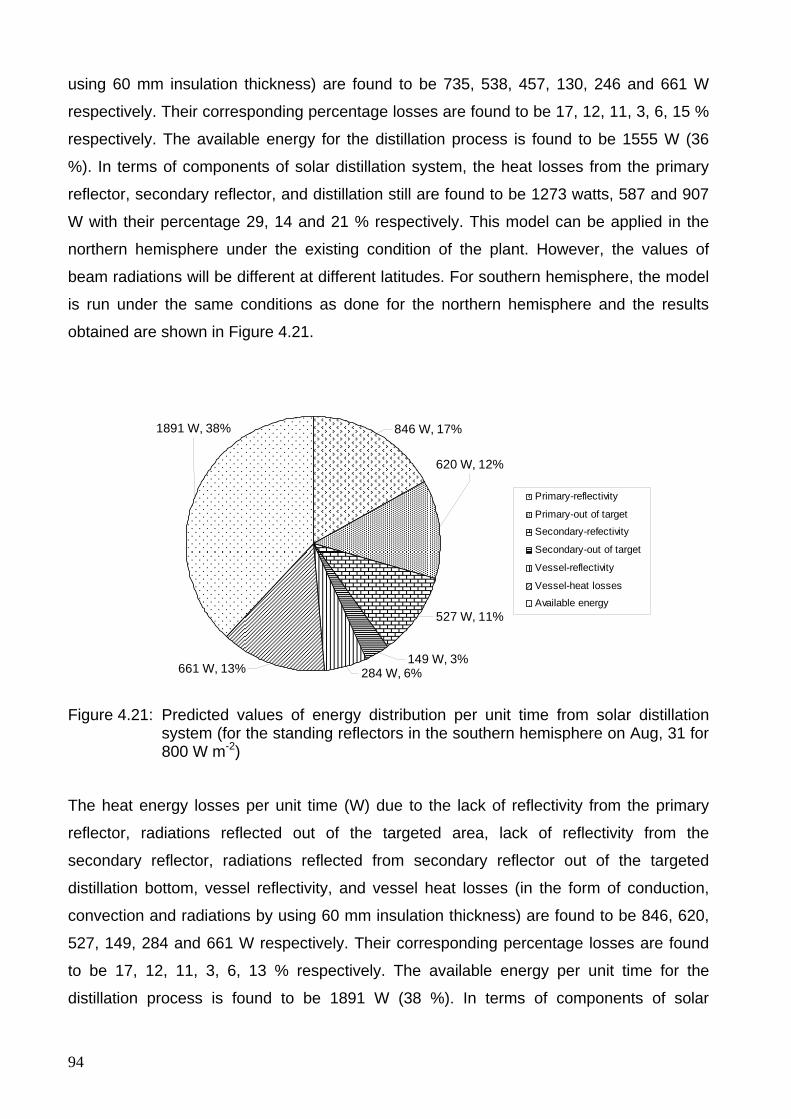
94
using 60 mm insulation thickness) are found to be 735, 538, 457, 130, 246 and 661 W
respectively. Their corresponding percentage losses are found to be 17, 12, 11, 3, 6, 15 %
respectively. The available energy for the distillation process is found to be 1555 W (36
%). In terms of components of solar distillation system, the heat losses from the primary
reflector, secondary reflector, and distillation still are found to be 1273 watts, 587 and 907
W with their percentage 29, 14 and 21 % respectively. This model can be applied in the
northern hemisphere under the existing condition of the plant. However, the values of
beam radiations will be different at different latitudes. For southern hemisphere, the model
is run under the same conditions as done for the northern hemisphere and the results
obtained are shown in Figure 4.21.
661 W, 13%
620 W, 12%
846 W, 17%1891 W, 38%
527 W, 11%
149 W, 3%284 W, 6%
Primary-reflectivity
Primary-out of target
Secondary-refectivity
Secondary-out of target
Vessel-reflectivity
Vessel-heat losses
Available energy
Figure 4.21: Predicted values of energy distribution per unit time from solar distillation system (for the standing reflectors in the southern hemisphere on Aug, 31 for 800 W m-2)
The heat energy losses per unit time (W) due to the lack of reflectivity from the primary
reflector, radiations reflected out of the targeted area, lack of reflectivity from the
secondary reflector, radiations reflected from secondary reflector out of the targeted
distillation bottom, vessel reflectivity, and vessel heat losses (in the form of conduction,
convection and radiations by using 60 mm insulation thickness) are found to be 846, 620,
527, 149, 284 and 661 W respectively. Their corresponding percentage losses are found
to be 17, 12, 11, 3, 6, 13 % respectively. The available energy per unit time for the
distillation process is found to be 1891 W (38 %). In terms of components of solar
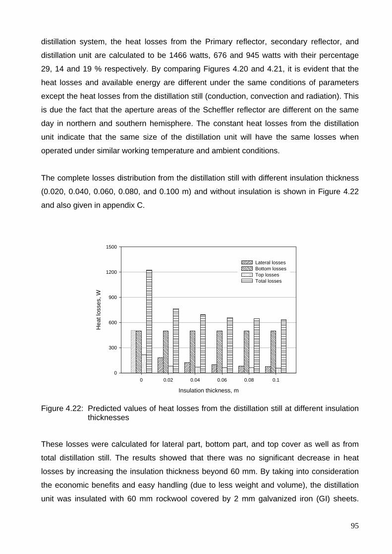
95
distillation system, the heat losses from the Primary reflector, secondary reflector, and
distillation unit are calculated to be 1466 watts, 676 and 945 watts with their percentage
29, 14 and 19 % respectively. By comparing Figures 4.20 and 4.21, it is evident that the
heat losses and available energy are different under the same conditions of parameters
except the heat losses from the distillation still (conduction, convection and radiation). This
is due the fact that the aperture areas of the Scheffler reflector are different on the same
day in northern and southern hemisphere. The constant heat losses from the distillation
unit indicate that the same size of the distillation unit will have the same losses when
operated under similar working temperature and ambient conditions.
The complete losses distribution from the distillation still with different insulation thickness
(0.020, 0.040, 0.060, 0.080, and 0.100 m) and without insulation is shown in Figure 4.22
and also given in appendix C.
Insulation thickness, m
0 0.02 0.04 0.06 0.08 0.1
Hea
t los
ses,
W
0
300
600
900
1200
1500
Lateral lossesBottom lossesTop lossesTotal losses
Figure 4.22: Predicted values of heat losses from the distillation still at different insulation thicknesses
These losses were calculated for lateral part, bottom part, and top cover as well as from
total distillation still. The results showed that there was no significant decrease in heat
losses by increasing the insulation thickness beyond 60 mm. By taking into consideration
the economic benefits and easy handling (due to less weight and volume), the distillation
unit was insulated with 60 mm rockwool covered by 2 mm galvanized iron (GI) sheets.
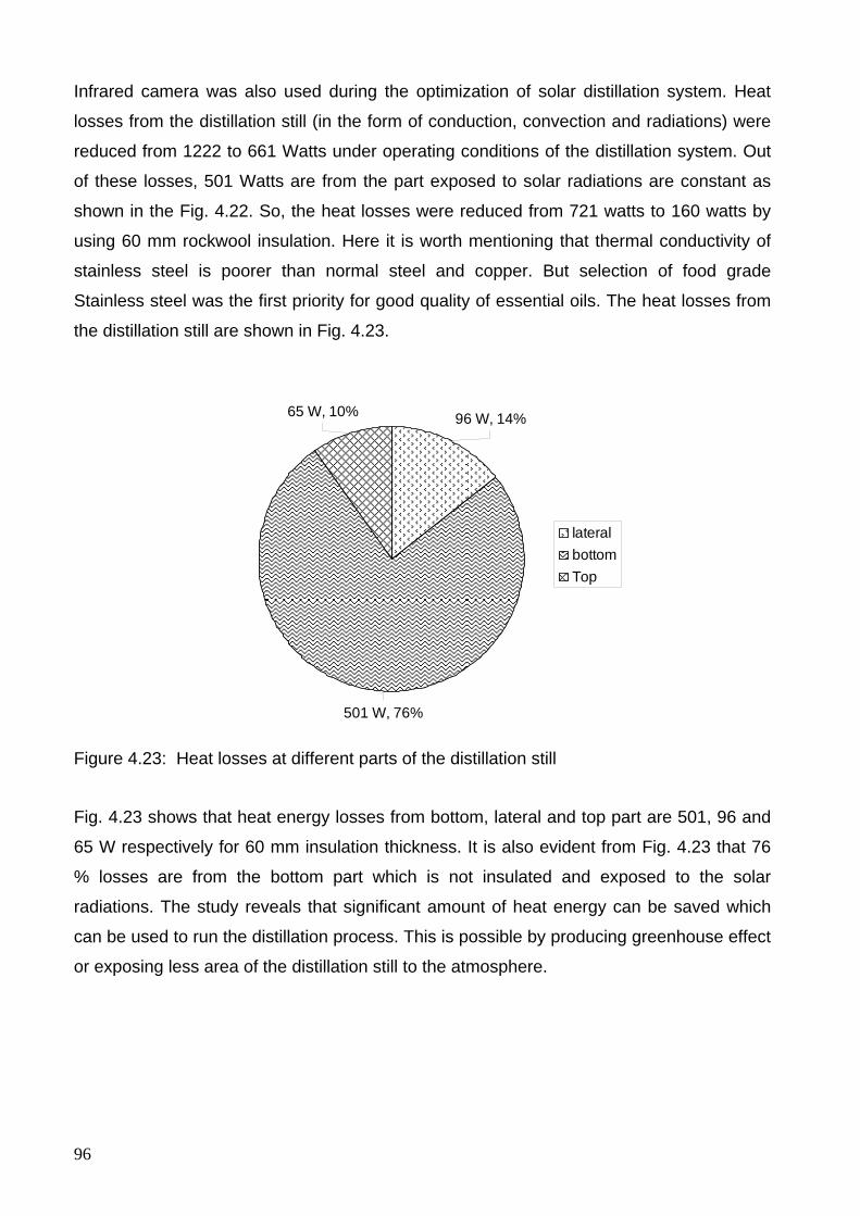
96
Infrared camera was also used during the optimization of solar distillation system. Heat
losses from the distillation still (in the form of conduction, convection and radiations) were
reduced from 1222 to 661 Watts under operating conditions of the distillation system. Out
of these losses, 501 Watts are from the part exposed to solar radiations are constant as
shown in the Fig. 4.22. So, the heat losses were reduced from 721 watts to 160 watts by
using 60 mm rockwool insulation. Here it is worth mentioning that thermal conductivity of
stainless steel is poorer than normal steel and copper. But selection of food grade
Stainless steel was the first priority for good quality of essential oils. The heat losses from
the distillation still are shown in Fig. 4.23.
501 W, 76%
96 W, 14%65 W, 10%
lateralbottomTop
Figure 4.23: Heat losses at different parts of the distillation still
Fig. 4.23 shows that heat energy losses from bottom, lateral and top part are 501, 96 and
65 W respectively for 60 mm insulation thickness. It is also evident from Fig. 4.23 that 76
% losses are from the bottom part which is not insulated and exposed to the solar
radiations. The study reveals that significant amount of heat energy can be saved which
can be used to run the distillation process. This is possible by producing greenhouse effect
or exposing less area of the distillation still to the atmosphere.
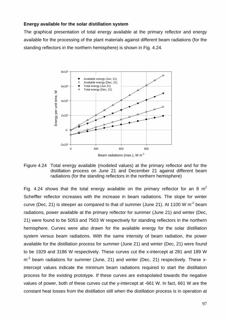
97
Energy available for the solar distillation system The graphical presentation of total energy available at the primary reflector and energy
available for the processing of the plant materials against different beam radiations (for the
standing reflectors in the northern hemisphere) is shown in Fig. 4.24.
Beam radiations (max.), W m-2
0 300 600 900
Ene
rgy
per u
nit t
ime,
W
-2x10³
0
2x10³
4x10³
6x10³
8x10³
Available energy (Jun, 21)Available energy (Dec, 21) Total energy (Jun 21) Total energy (Dec, 21)
Figure 4.24 Total energy available (modeled values) at the primary reflector and for the distillation process on June 21 and December 21 against different beam radiations (for the standing reflectors in the northern hemisphere)
Fig. 4.24 shows that the total energy available on the primary reflector for an 8 m2
Scheffler reflector increases with the increase in beam radiations. The slope for winter
curve (Dec, 21) is steeper as compared to that of summer (June 21). At 1100 W m-2 beam
radiations, power available at the primary reflector for summer (June 21) and winter (Dec,
21) were found to be 5053 and 7503 W respectively for standing reflectors in the northern
hemisphere. Curves were also drawn for the available energy for the solar distillation
system versus beam radiations. With the same intensity of beam radiation, the power
available for the distillation process for summer (June 21) and winter (Dec, 21) were found
to be 1929 and 3186 W respectively. These curves cut the x-intercept at 281 and 189 W
m-2 beam radiations for summer (June, 21) and winter (Dec, 21) respectively. These x-
intercept values indicate the minimum beam radiations required to start the distillation
process for the existing prototype. If these curves are extrapolated towards the negative
values of power, both of these curves cut the y-intercept at -661 W. In fact, 661 W are the
constant heat losses from the distillation still when the distillation process is in operation at
98
100 °C. The results of solar distillation model provide useful information to predict the total
energy available on the reflector and energy available for the distillation process against a
wide range of beam radiations.
4.8 Performance evaluation of the solar distillation system The principal expression for the efficiency calculation of solar distillation system is given
below
10010
0
3
∫
=
=
p
tsave
p
tdtAGb
E%)(efficiencySystem η (4.47)
Where Ep is the total heat energy during distillation process, t is the time during the
distillation process, Gbave is the beam radiation at time t, As is the aperture area of the
Scheffler reflector.
The total heat energy (Ep) during distillation process of herbs in kWh can be calculated by
the following expression
(4.48)
where mw is the mass of water used in the still (mw ≥ 15 kg, volume equivalent to the
bottom area of the distillation still exposed to solar radiation), Mw is the moisture content of
herbs (wet basis), mh is the mass of herbs, ΔT is the change in temperature, cw is the
specific heat of water at constant pressure, ms is the mass of steam produced, hfg is the
latent heat of vaporization (2260 kJ kg-1 for water at atmospheric pressure), cf is the
specific heat of fiber, x is the dryness fraction of steam.
Determination of dryness fraction The values of dryness fraction are used to evaluate the system during the steam
generation phase. The calorimeter with mass 0.0818 kg is insulated on all sides to reduce
the heat losses and a thermometer is fixed on the top side to record temperature. An
insulated pipe connects the top of the distillation still to the barrel calorimeter to take the
steam sample. Steam is injected into 0.5 kg water sample in the barrel calorimeter. The
( ) ( )[ ]3600
1 fgsfwhwhwwp
hmxTcMmcmMmE
+Δ−++=
99
weight of steam added and rise in temperature are recorded when the steady state
temperature of water in the calorimeter is reached. The principal formula for the dryness
fraction, x, is given by Khurmi & Gupta (2005)
( )( ) ( )fg
csw
fgsc
ccccwc
hTTc
hmTTcmmx 212 −
−−+
= (4.49)
Where mwc is the mass of water in calorimeter, cw is the specific heat of water, mc is the
mass of calorimeter, cc is the specific heat of the calorimeter, T2c is the final temperature of
water and calorimeter, T1c is the initial temperature of water and calorimeter, msc is the
mass of steam added in the calorimeter, Ts is the temperature of steam formation at
pressure P, hfg is the latent heat of vaporization of water.
The mass and specific heat of the calorimeter for the existing distillation system are 0.818
kg and 0.45 kJ kg-1 K-1 respectively. For the determination of dryness fraction, 0.5 kg of
water is taken in the calorimeter. The latent heat of vaporization of water at atmospheric
pressure is taken as 2260 kJ kg-1. Eq. (4.49) is simplified by designating these constant
values under the operating conditions of the solar distillation unit and is rewritten as:
( ) ( )cs
sc
cc TTCm
TTCx 22
121 −−−
= (4.50)
where C1 and C2 are constants for the barrel calorimeter used during distillation
experiments and are calculated to be 0.00094 and 0.00185 respectively.
In order to evaluate the performance of the solar distillation system by using herbs during
small time intervals, the above equation can be re-written as:
∑∑q
jsjj
p
iip mxCTCE
14
13
==+Δ= (4.51)
where C3 and C4 are constants for the particular batch during solar distillation
experiments.
The values of C3 and C4 are given as:
100
( ) ( )3600
13
fwhwhww cMmcmMmC −++=
36004fgh
C =
(C4 =0.62777 at atmospheric pressure)
The former part of Eq. (4.51) gives the sum of total sensible heat energy (taken in small
intervals ranging from the start of the experiment to reaching boiling point “p”) and the
latter part of the equation gives the sum of total latent heat energy (taken in small intervals
starting from the first interval of steam generation to the last interval of steam generation
“q” where the distillation experiment is stopped).
Funk (2000) described the procedure for evaluation of different types of solar
concentrators. He explained that the influence of test conditions on results can be
minimized if uncontrolled variables are held to certain ranges. He used water for the
evaluation of the cookers in terms of power. For the performance test with water only, Eq.
(4.51) can be used with C3 = mwcw/3600 for water only. The average power available, Pave,
during the experiment is given as
p
pave t
EP = (4.52)
where tP is the total process time of the distillation experiment
Several experiments were carried out to evaluate the performance of the system under
field conditions. Within the beam radiation range of 700-800 W m-2, the temperature
available at the focus was found to be between 300-400 °C. Scheffler (2006) showed that
about half of the solar power collected by the reflector becomes finally available in the
cooking vessel. Details of one performance evaluation of the solar distillation system with
20 l of water on August 31, 2008 from 9:06 to 16:00 hour (test duration = 5.9 hour) are
shown in Fig. 4.25.
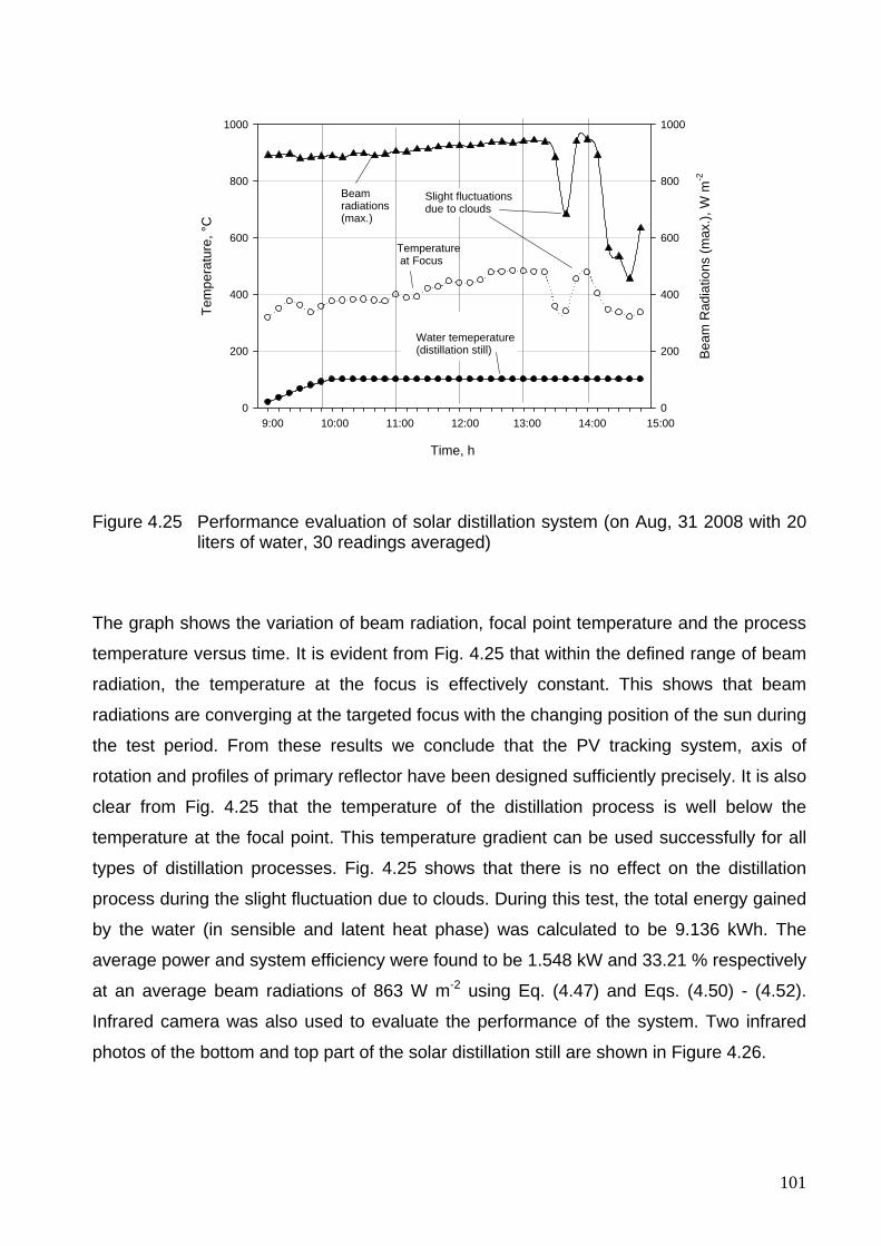
101
Time, h
Tem
pera
ture
, °C
0
200
400
600
800
1000
Bea
m R
adia
tions
(max
.), W
m-2
0
200
400
600
800
1000
Beamradiations(max.)
Temperature at Focus
Slight fluctuations due to clouds
9:00 10:00 11:00 12:00 13:00 14:00 15:00
Water temeperature(distillation still)
Figure 4.25 Performance evaluation of solar distillation system (on Aug, 31 2008 with 20 liters of water, 30 readings averaged)
The graph shows the variation of beam radiation, focal point temperature and the process
temperature versus time. It is evident from Fig. 4.25 that within the defined range of beam
radiation, the temperature at the focus is effectively constant. This shows that beam
radiations are converging at the targeted focus with the changing position of the sun during
the test period. From these results we conclude that the PV tracking system, axis of
rotation and profiles of primary reflector have been designed sufficiently precisely. It is also
clear from Fig. 4.25 that the temperature of the distillation process is well below the
temperature at the focal point. This temperature gradient can be used successfully for all
types of distillation processes. Fig. 4.25 shows that there is no effect on the distillation
process during the slight fluctuation due to clouds. During this test, the total energy gained
by the water (in sensible and latent heat phase) was calculated to be 9.136 kWh. The
average power and system efficiency were found to be 1.548 kW and 33.21 % respectively
at an average beam radiations of 863 W m-2 using Eq. (4.47) and Eqs. (4.50) - (4.52).
Infrared camera was also used to evaluate the performance of the system. Two infrared
photos of the bottom and top part of the solar distillation still are shown in Figure 4.26.
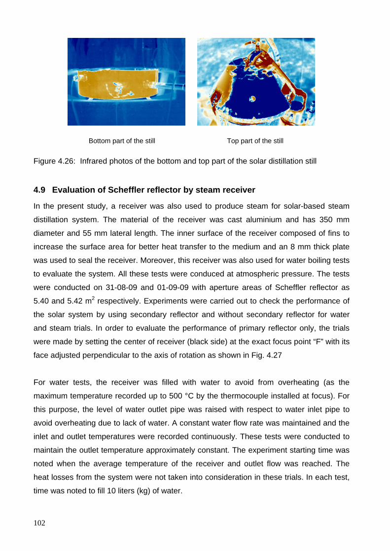
102
Bottom part of the still Top part of the still
Figure 4.26: Infrared photos of the bottom and top part of the solar distillation still
4.9 Evaluation of Scheffler reflector by steam receiver
In the present study, a receiver was also used to produce steam for solar-based steam
distillation system. The material of the receiver was cast aluminium and has 350 mm
diameter and 55 mm lateral length. The inner surface of the receiver composed of fins to
increase the surface area for better heat transfer to the medium and an 8 mm thick plate
was used to seal the receiver. Moreover, this receiver was also used for water boiling tests
to evaluate the system. All these tests were conduced at atmospheric pressure. The tests
were conducted on 31-08-09 and 01-09-09 with aperture areas of Scheffler reflector as
5.40 and 5.42 m2 respectively. Experiments were carried out to check the performance of
the solar system by using secondary reflector and without secondary reflector for water
and steam trials. In order to evaluate the performance of primary reflector only, the trials
were made by setting the center of receiver (black side) at the exact focus point “F” with its
face adjusted perpendicular to the axis of rotation as shown in Fig. 4.27
For water tests, the receiver was filled with water to avoid from overheating (as the
maximum temperature recorded up to 500 °C by the thermocouple installed at focus). For
this purpose, the level of water outlet pipe was raised with respect to water inlet pipe to
avoid overheating due to lack of water. A constant water flow rate was maintained and the
inlet and outlet temperatures were recorded continuously. These tests were conducted to
maintain the outlet temperature approximately constant. The experiment starting time was
noted when the average temperature of the receiver and outlet flow was reached. The
heat losses from the system were not taken into consideration in these trials. In each test,
time was noted to fill 10 liters (kg) of water.
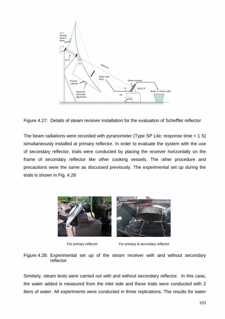
103
51.3°
4206 mm
ω= I rev/dayEast to West
B
Seasonal telescopic adjustment
598
117
Primeryreflector
Steam receiver
90-51.3°
Water inlet level
Water or steam outlet
F
Figure 4.27: Details of steam receiver installation for the evaluation of Scheffler reflector
The beam radiations were recorded with pyranometer (Type SP Lite: response time < 1 S)
simultaneously installed at primary reflector. In order to evaluate the system with the use
of secondary reflector, trials were conducted by placing the receiver horizontally on the
frame of secondary reflector like other cooking vessels. The other procedure and
precautions were the same as discussed previously. The experimental set up during the
trials is shown in Fig. 4.28
For primary reflector For primary & secondary reflector
Figure 4.28: Experimental set up of the steam receiver with and without secondary reflector
Similarly, steam tests were carried out with and without secondary reflector. In this case,
the water added is measured from the inlet side and these trials were conducted with 2
liters of water. All experiments were conducted in three replications. The results for water
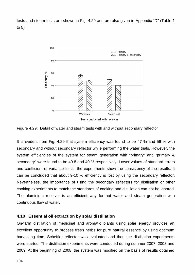
104
tests and steam tests are shown in Fig. 4.29 and are also given in Appendix “D” (Table 1
to 5)
Test conducted with receiver
Water test Steam test
Effi
cien
cy, %
0
20
40
60
80
100PrimaryPrimary & secondary
Figure 4.29: Detail of water and steam tests with and without secondary reflector
It is evident from Fig. 4.29 that system efficiency was found to be 47 % and 56 % with
secondary and without secondary reflector while performing the water trials. However, the
system efficiencies of the system for steam generation with “primary” and “primary &
secondary” were found to be 49.8 and 40 % respectively. Lower values of standard errors
and coefficient of variance for all the experiments show the consistency of the results. It
can be concluded that about 9-10 % efficiency is lost by using the secondary reflector.
Nevertheless, the importance of using the secondary reflectors for distillation or other
cooking experiments to match the standards of cooking and distillation can not be ignored.
The aluminium receiver is an efficient way for hot water and steam generation with
continuous flow of water.
4.10 Essential oil extraction by solar distillation On-farm distillation of medicinal and aromatic plants using solar energy provides an
excellent opportunity to process fresh herbs for pure natural essence by using optimum
harvesting time. Scheffler reflector was evaluated and then the distillation experiments
were started. The distillation experiments were conducted during summer 2007, 2008 and
2009. At the beginning of 2008, the system was modified on the basis of results obtained
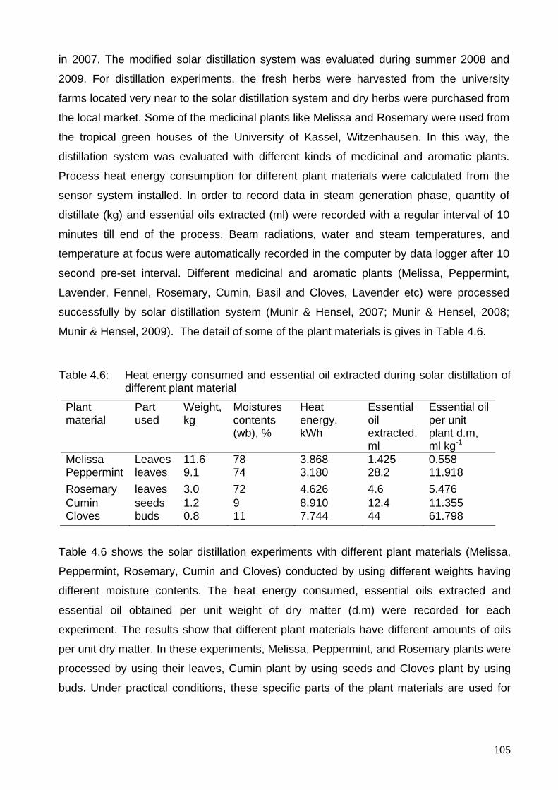
105
in 2007. The modified solar distillation system was evaluated during summer 2008 and
2009. For distillation experiments, the fresh herbs were harvested from the university
farms located very near to the solar distillation system and dry herbs were purchased from
the local market. Some of the medicinal plants like Melissa and Rosemary were used from
the tropical green houses of the University of Kassel, Witzenhausen. In this way, the
distillation system was evaluated with different kinds of medicinal and aromatic plants.
Process heat energy consumption for different plant materials were calculated from the
sensor system installed. In order to record data in steam generation phase, quantity of
distillate (kg) and essential oils extracted (ml) were recorded with a regular interval of 10
minutes till end of the process. Beam radiations, water and steam temperatures, and
temperature at focus were automatically recorded in the computer by data logger after 10
second pre-set interval. Different medicinal and aromatic plants (Melissa, Peppermint,
Lavender, Fennel, Rosemary, Cumin, Basil and Cloves, Lavender etc) were processed
successfully by solar distillation system (Munir & Hensel, 2007; Munir & Hensel, 2008;
Munir & Hensel, 2009). The detail of some of the plant materials is gives in Table 4.6.
Table 4.6: Heat energy consumed and essential oil extracted during solar distillation of
different plant material
Plant material
Part used
Weight, kg
Moistures contents (wb), %
Heat energy, kWh
Essential oil extracted, ml
Essential oil per unit plant d.m, ml kg-1
Melissa Leaves 11.6 78 3.868 1.425 0.558 Peppermint leaves 9.1 74 3.180 28.2 11.918 Rosemary leaves 3.0 72 4.626 4.6 5.476 Cumin seeds 1.2 9 8.910 12.4 11.355 Cloves buds 0.8 11 7.744 44 61.798
Table 4.6 shows the solar distillation experiments with different plant materials (Melissa,
Peppermint, Rosemary, Cumin and Cloves) conducted by using different weights having
different moisture contents. The heat energy consumed, essential oils extracted and
essential oil obtained per unit weight of dry matter (d.m) were recorded for each
experiment. The results show that different plant materials have different amounts of oils
per unit dry matter. In these experiments, Melissa, Peppermint, and Rosemary plants were
processed by using their leaves, Cumin plant by using seeds and Cloves plant by using
buds. Under practical conditions, these specific parts of the plant materials are used for
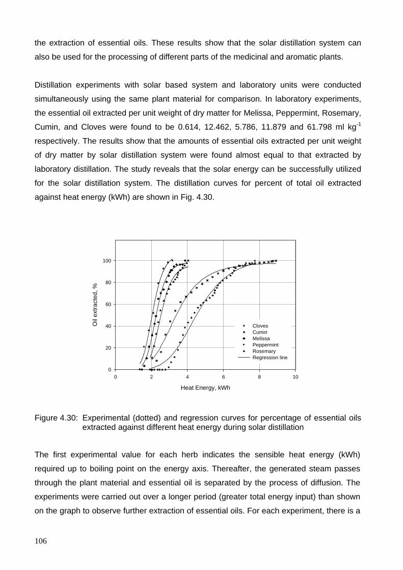
106
the extraction of essential oils. These results show that the solar distillation system can
also be used for the processing of different parts of the medicinal and aromatic plants.
Distillation experiments with solar based system and laboratory units were conducted
simultaneously using the same plant material for comparison. In laboratory experiments,
the essential oil extracted per unit weight of dry matter for Melissa, Peppermint, Rosemary,
Cumin, and Cloves were found to be 0.614, 12.462, 5.786, 11.879 and 61.798 ml kg-1
respectively. The results show that the amounts of essential oils extracted per unit weight
of dry matter by solar distillation system were found almost equal to that extracted by
laboratory distillation. The study reveals that the solar energy can be successfully utilized
for the solar distillation system. The distillation curves for percent of total oil extracted
against heat energy (kWh) are shown in Fig. 4.30.
Heat Energy, kWh
0 2 4 6 8 10
Oil
extra
cted
, %
0
20
40
60
80
100
ClovesCuminMelissa Peppermint RosemaryRegression line
Figure 4.30: Experimental (dotted) and regression curves for percentage of essential oils extracted against different heat energy during solar distillation
The first experimental value for each herb indicates the sensible heat energy (kWh)
required up to boiling point on the energy axis. Thereafter, the generated steam passes
through the plant material and essential oil is separated by the process of diffusion. The
experiments were carried out over a longer period (greater total energy input) than shown
on the graph to observe further extraction of essential oils. For each experiment, there is a
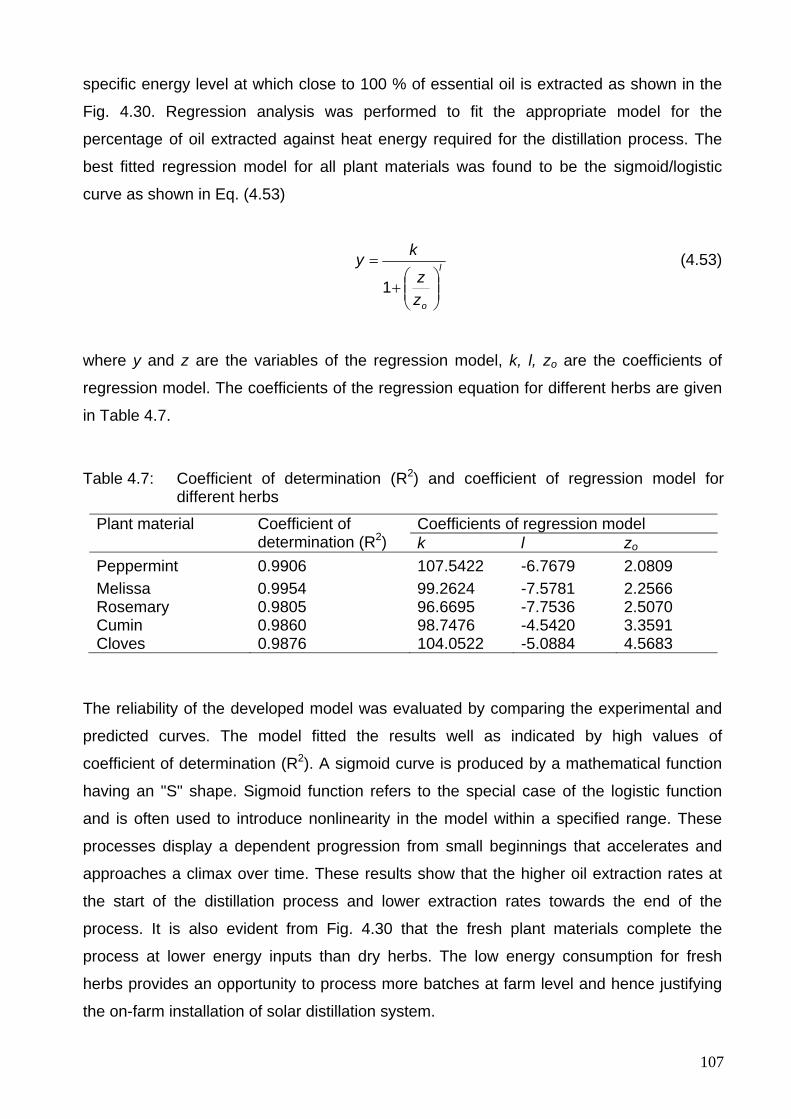
107
specific energy level at which close to 100 % of essential oil is extracted as shown in the
Fig. 4.30. Regression analysis was performed to fit the appropriate model for the
percentage of oil extracted against heat energy required for the distillation process. The
best fitted regression model for all plant materials was found to be the sigmoid/logistic
curve as shown in Eq. (4.53)
l
ozz
ky
⎟⎟⎠
⎞⎜⎜⎝
⎛+
=
1
(4.53)
where y and z are the variables of the regression model, k, l, zo are the coefficients of
regression model. The coefficients of the regression equation for different herbs are given
in Table 4.7.
Table 4.7: Coefficient of determination (R2) and coefficient of regression model for different herbs
Plant material Coefficient of determination (R2)
Coefficients of regression model k l zo
Peppermint 0.9906 107.5422 -6.7679 2.0809 Melissa 0.9954 99.2624 -7.5781 2.2566 Rosemary 0.9805 96.6695 -7.7536 2.5070 Cumin 0.9860 98.7476 -4.5420 3.3591 Cloves 0.9876 104.0522 -5.0884 4.5683
The reliability of the developed model was evaluated by comparing the experimental and
predicted curves. The model fitted the results well as indicated by high values of
coefficient of determination (R2). A sigmoid curve is produced by a mathematical function
having an "S" shape. Sigmoid function refers to the special case of the logistic function
and is often used to introduce nonlinearity in the model within a specified range. These
processes display a dependent progression from small beginnings that accelerates and
approaches a climax over time. These results show that the higher oil extraction rates at
the start of the distillation process and lower extraction rates towards the end of the
process. It is also evident from Fig. 4.30 that the fresh plant materials complete the
process at lower energy inputs than dry herbs. The low energy consumption for fresh
herbs provides an opportunity to process more batches at farm level and hence justifying
the on-farm installation of solar distillation system.
108
In addition to these five experiments shown in Table 4.6, many experiments were
conducted with Melissa and Peppermint as a plenty of these plant materials were available
at the experimental farms near solar distillation system. In summer seasons, the solar
distillation system can be operated for 12 hours a day from 08:00 hours to 20:00 hours. In
section 4.8, the average power and system efficiency were found to be 1.548 kW and
33.21 % respectively during a sunny day. About 18.58 kWh energy can be obtained for
processing under similar conditions during 12 hours in one day. In several experiments,
total energy consumptions for the processing of 10 kg batch of Melissa and Peppermint
were recorded to be from 3 to 4 kWh. Therefore, 4-5 batches with 10 kg plant material
were processed successfully using fresh herbs. These figures show the potential of solar
distillation system during sunny days at the installed site.
The solar distillation unit behaves simultaneously as a boiler for the generation of steam
as well as provides necessary column height for easy and simple oil condensation when
used on the farm. The safety mountings and the instrumentation provide useful
information to run the unit safely. The present research work was carried out using an 8
m2 surface area of the solar concentrator which corresponds to 400 mm diameter for the
distillation still. The capacity of the solar distillation system can be enhanced by increasing
the solar concentrator area and other components of the distillation unit accordingly. This
solar renewable energy technology is free of operational costs, environmental friendly and
provides an excellent opportunity for on-farm processing of medicinal and aromatic plants.
A large number of experiments were conduced by using the solar distillation system. The
detail of some of the plant materials are given below.
4.10.1 Distillation experiments with Lemon Balm (Melissa officinalis L.) Lemon Balm (Melissa officinalis L.) is important due to its medical properties and its use as
tea. Its essential oil is required mainly in the pharmaceutical, food and cosmetic industries.
The properties of the plant extracts include sedative, relaxing, antibacterial, antiviral, and
antipasmotic effects (Ayanoglu, 2005; Heeger, 1980). The main components of the
essential oil are citral, citronellal and linalool. By means of gas chromatography studies of
the essential oil, 70 components are known (Basta, 2005; Blum, 2005; Bomme, 2001). The
lemon balm has low essential oil content ranging from 0.05 and 0.12 % volume (Basta,
2005).
109
Beside the solar campus, huge quantities of different herbs and medicinal plants have
been planted in the University of Kassel experimental farms (one hectare area),
Witzenhausen, Germany. Among all these plants, Mellissa was one of the most extensive
planted medicinal plants for the research purposes on drying and distillation. Moreover,
Melissa remained available during the entire period of research in the tropical green house
to conduct experiment during winter season. A large number of distillation experiments
were conducted with Lemon Balm (variety Citronella) during 2007, 2008 and 2009 to
evaluate the performance of the solar distillation system.
These experiments were conducted with fresh, dry, and chopped Mellissa. In the
experiments for fresh Melissa, 10 kg batches of fresh Melissa were taken (at 78 %
moisture contents with ± 2 % variation) and they were processed just after harvesting. In
order to conduct experiments with dried Melissa, 10 kg Melissa on fresh weight basis
(same weight was used as for fresh experiments) were dried in the solar tunnel dryer
(Hohenheim design) under optimum conditions, the design of solar tunnel drier is shown in
Appendix E. The drying was carried out until a moisture content of 10 % was achieved
(Cuervo & Hensel, 2008). Experiments were also conducted with chopped Melissa to
increase the bulk density and to break the walls of the plants to increase the exposed
surface area of the plant material. In some experiments, chopping was also done with the
help of chopping machine to increase the preparatory index. The risk of losing
considerable amount of essential oil exists while chopping the plant material (Öztekin &
Martinov, 2007). For this purpose, the chopping was done carefully to avoid the volatile
losses from the plant material into the open atmosphere. The process curves were drawn
for fresh, dried and chopped Melissa with solar distillation system as shown in the Fig.
4.31.
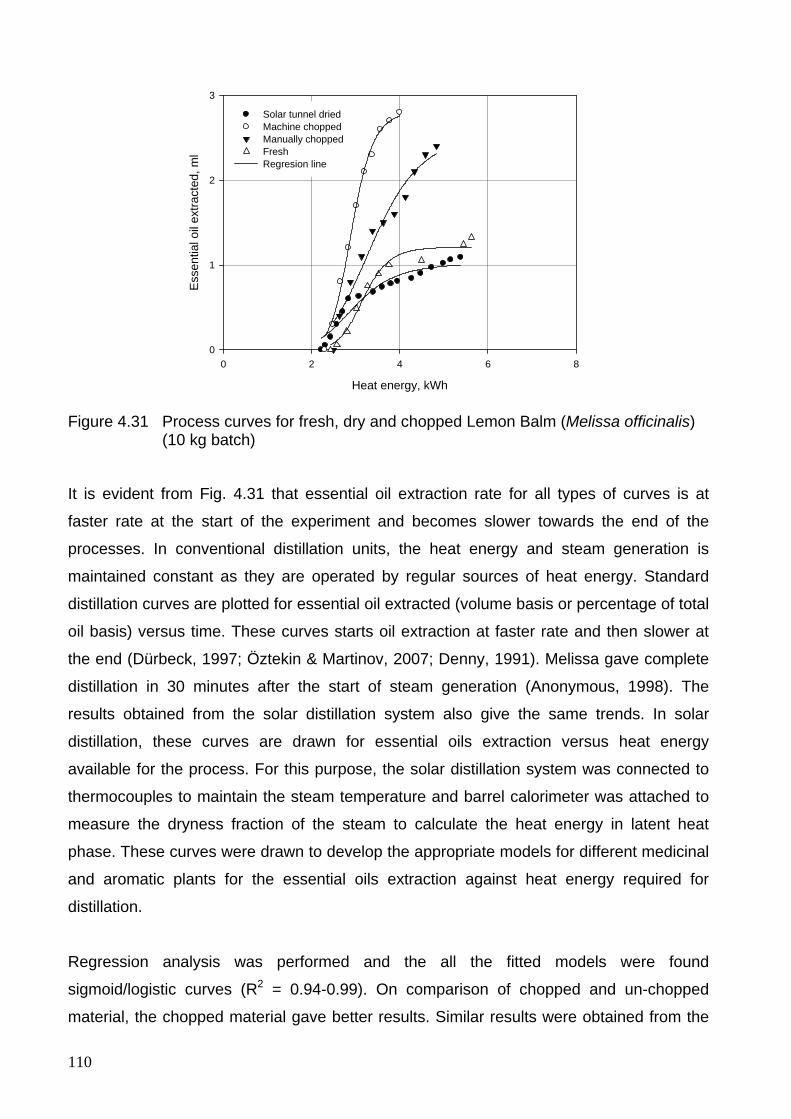
110
Heat energy, kWh
0 2 4 6 8
Ess
entia
l oil
extra
cted
, ml
0
1
2
3
Solar tunnel driedMachine choppedManually choppedFreshRegresion line
Figure 4.31 Process curves for fresh, dry and chopped Lemon Balm (Melissa officinalis) (10 kg batch)
It is evident from Fig. 4.31 that essential oil extraction rate for all types of curves is at
faster rate at the start of the experiment and becomes slower towards the end of the
processes. In conventional distillation units, the heat energy and steam generation is
maintained constant as they are operated by regular sources of heat energy. Standard
distillation curves are plotted for essential oil extracted (volume basis or percentage of total
oil basis) versus time. These curves starts oil extraction at faster rate and then slower at
the end (Dürbeck, 1997; Öztekin & Martinov, 2007; Denny, 1991). Melissa gave complete
distillation in 30 minutes after the start of steam generation (Anonymous, 1998). The
results obtained from the solar distillation system also give the same trends. In solar
distillation, these curves are drawn for essential oils extraction versus heat energy
available for the process. For this purpose, the solar distillation system was connected to
thermocouples to maintain the steam temperature and barrel calorimeter was attached to
measure the dryness fraction of the steam to calculate the heat energy in latent heat
phase. These curves were drawn to develop the appropriate models for different medicinal
and aromatic plants for the essential oils extraction against heat energy required for
distillation.
Regression analysis was performed and the all the fitted models were found
sigmoid/logistic curves (R2 = 0.94-0.99). On comparison of chopped and un-chopped
material, the chopped material gave better results. Similar results were obtained from the
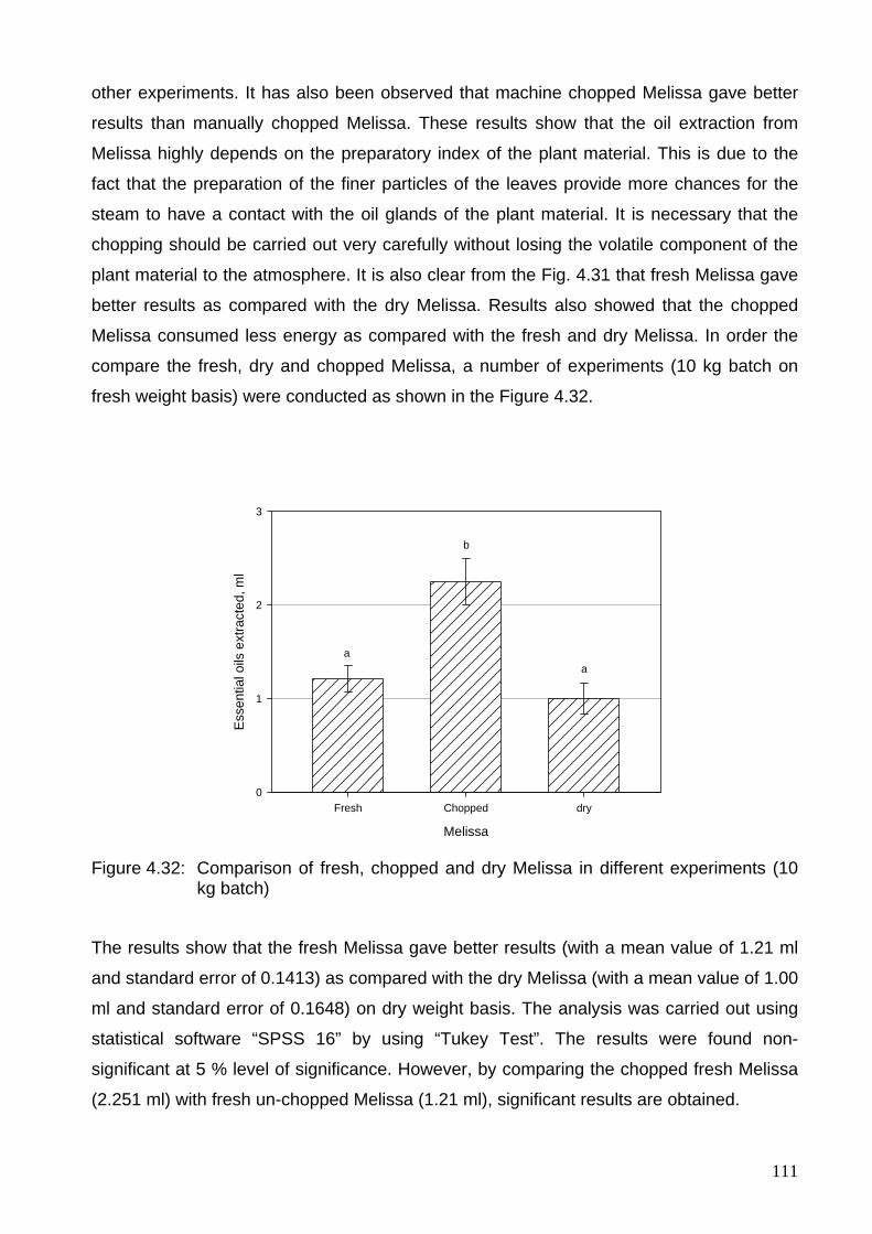
111
other experiments. It has also been observed that machine chopped Melissa gave better
results than manually chopped Melissa. These results show that the oil extraction from
Melissa highly depends on the preparatory index of the plant material. This is due to the
fact that the preparation of the finer particles of the leaves provide more chances for the
steam to have a contact with the oil glands of the plant material. It is necessary that the
chopping should be carried out very carefully without losing the volatile component of the
plant material to the atmosphere. It is also clear from the Fig. 4.31 that fresh Melissa gave
better results as compared with the dry Melissa. Results also showed that the chopped
Melissa consumed less energy as compared with the fresh and dry Melissa. In order the
compare the fresh, dry and chopped Melissa, a number of experiments (10 kg batch on
fresh weight basis) were conducted as shown in the Figure 4.32.
Melissa
Fresh Chopped dry
Ess
entia
l oils
ext
ract
ed, m
l
0
1
2
3
aa
b
Figure 4.32: Comparison of fresh, chopped and dry Melissa in different experiments (10 kg batch)
The results show that the fresh Melissa gave better results (with a mean value of 1.21 ml
and standard error of 0.1413) as compared with the dry Melissa (with a mean value of 1.00
ml and standard error of 0.1648) on dry weight basis. The analysis was carried out using
statistical software “SPSS 16” by using “Tukey Test”. The results were found non-
significant at 5 % level of significance. However, by comparing the chopped fresh Melissa
(2.251 ml) with fresh un-chopped Melissa (1.21 ml), significant results are obtained.
112
According to Jud (Cited in Müller, 1992), by increasing the drying temperature from 30 °C
to 55 °C, essential oil losses increase by 15 percent and the drug color changes from
green to gray. Drying temperature usually has an influence on the temperature sensible
components of essential oil. Cuervo & Hensel (2008) have also concluded the similar
results. Moreover, the drying process necessitates an enormous amount of thermal and
electrical energy (Fargali et al., 2008). In the present study, many experiments were
conducted to compare the fresh and dry Melissa per unit dry matter. Even though fresh
herbs gave better results but statistically these results were found non-significant. In fact,
these drying trials were conducted using solar tunnel dryer in the permissible temperature
range to avoid the burning and decomposition of the essential oil of the plant material. The
study concludes that the dry Melissa can also be distilled successfully for essential oil
extraction if dried in the permissible temperature range.
Öztekin & Martinov (2007) investigated that during distillation experiments, the plant
materials get denser by absorbing water and the fresh steam is not able to move it, and
the pores in the randomly places material at the beginning gets larger. In this way, only
some part of the material is in touch with the steam and absorbing essential oil is far from
complete. This can be prevented by using mixers such as an auger inside the still body or
chopping of plant material before processing. Many experiments were performed to
compare chopped and un-chopped Melissa per unit weight of dry matter, highly significant
results were obtained. These results show that chopping is an effective way to get the full
contents of the essential oils by exposing the more surface area of the plant material to the
steam.
4.10.1.1 Distillation experiments with Peppermint varieties (Mentha piperita L, Mentha spec., Mentha spicata)
Three varieties of Peppermint were available to conduct the distillation experiments at the
solar distillation experimental site. These varieties were Mentha Piperita L, Mentha spec.
and Mentha spicata as shown in Appendix F. The health benefits of Peppermint oil include
its ability to treat indigestion, respiratory problems, headache, nausea, fever, dental care,
urinary track infection, stomach and bowel spasms and pain. It also increase immunity to
diseases, improve blood circulation, It is further believed that peppermint oil is useful for
treating cancer and tuberculosis. Due to the presence of menthol, menthone and menthyl
esters, peppermint and peppermint oil find wide applications in manufacture of soap,
shampoo, cigarette, toothpaste, chewing gum, tea and ice cream. Peppermint is a cross
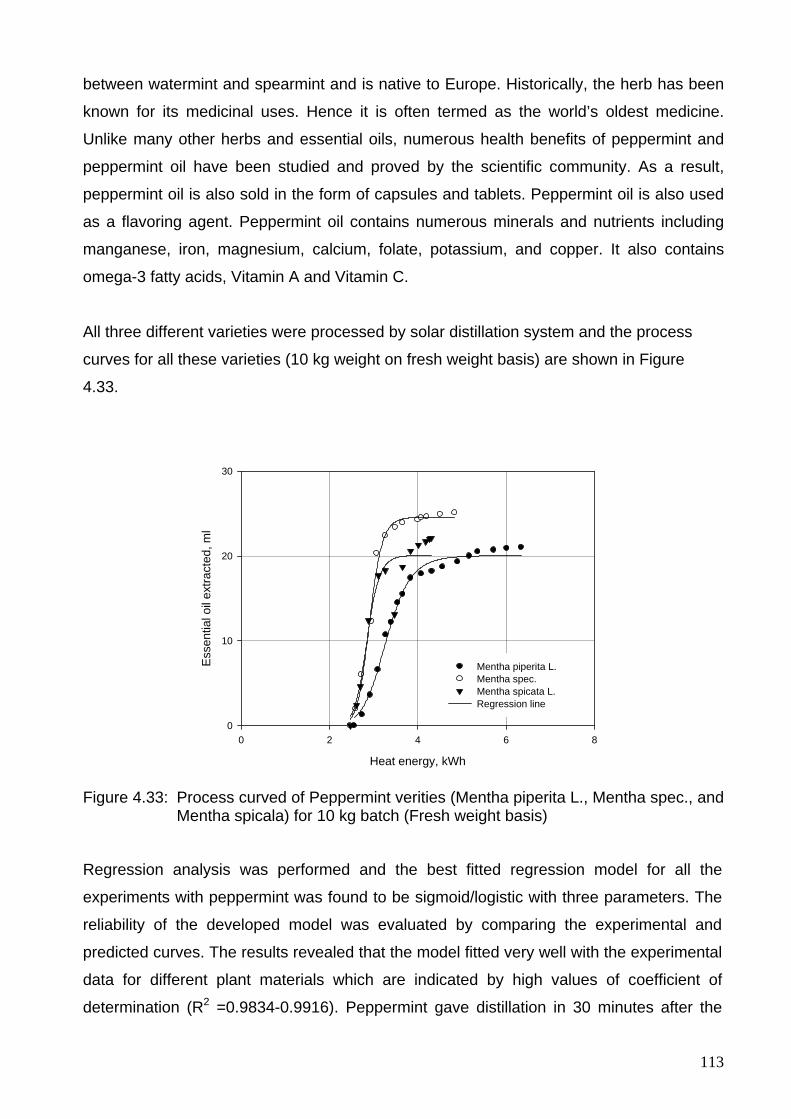
113
between watermint and spearmint and is native to Europe. Historically, the herb has been
known for its medicinal uses. Hence it is often termed as the world’s oldest medicine.
Unlike many other herbs and essential oils, numerous health benefits of peppermint and
peppermint oil have been studied and proved by the scientific community. As a result,
peppermint oil is also sold in the form of capsules and tablets. Peppermint oil is also used
as a flavoring agent. Peppermint oil contains numerous minerals and nutrients including
manganese, iron, magnesium, calcium, folate, potassium, and copper. It also contains
omega-3 fatty acids, Vitamin A and Vitamin C.
All three different varieties were processed by solar distillation system and the process
curves for all these varieties (10 kg weight on fresh weight basis) are shown in Figure
4.33.
Heat energy, kWh
0 2 4 6 8
Ess
entia
l oil
extra
cted
, ml
0
10
20
30
Mentha piperita L.Mentha spec.Mentha spicata L.Regression line
Figure 4.33: Process curved of Peppermint verities (Mentha piperita L., Mentha spec., and Mentha spicala) for 10 kg batch (Fresh weight basis)
Regression analysis was performed and the best fitted regression model for all the
experiments with peppermint was found to be sigmoid/logistic with three parameters. The
reliability of the developed model was evaluated by comparing the experimental and
predicted curves. The results revealed that the model fitted very well with the experimental
data for different plant materials which are indicated by high values of coefficient of
determination (R2 =0.9834-0.9916). Peppermint gave distillation in 30 minutes after the
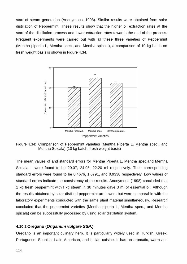
114
start of steam generation (Anonymous, 1998). Similar results were obtained from solar
distillation of Peppermint. These results show that the higher oil extraction rates at the
start of the distillation process and lower extraction rates towards the end of the process.
Frequent experiments were carried out with all these three varieties of Peppermint
(Mentha piperita L, Mentha spec., and Mentha spicala), a comparison of 10 kg batch on
fresh weight basis is shown in Figure 4.34.
Pepperrmint varieties
Mentha Piperita L Mentha spec. Mentha spicata L.
Ess
entia
l oils
ext
ract
ed. m
l
0
10
20
30
Figure 4.34: Comparison of Peppermint varieties (Mentha Piperta L, Mentha spec., and Mentha Spicala) (10 kg batch, fresh weight basis)
The mean values of and standard errors for Mentha Piperta L, Mentha spec.and Mentha
Spicala L were found to be 20.07, 24.95, 22.20 ml respectively. Their corresponding
standard errors were found to be 0.4676, 1.6791, and 0.9338 respectively. Low values of
standard errors indicate the consistency of the results. Anonymous (1998) concluded that
1 kg fresh peppermint with I kg steam in 30 minutes gave 3 ml of essential oil. Although
the results obtained by solar distilled peppermint are lowers but were comparable with the
laboratory experiments conducted with the same plant material simultaneously. Research
concluded that the peppermint varieties (Mentha piperta L, Mentha spec., and Mentha
spicala) can be successfully processed by using solar distillation system.
4.10.2 Oregano (Origanum vulgare SSP.) Oregano is an important culinary herb. It is particularly widely used in Turkish, Greek,
Portuguese, Spanish, Latin American, and Italian cuisine. It has an aromatic, warm and
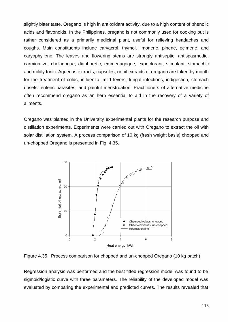
115
slightly bitter taste. Oregano is high in antioxidant activity, due to a high content of phenolic
acids and flavonoids. In the Philippines, oregano is not commonly used for cooking but is
rather considered as a primarily medicinal plant, useful for relieving headaches and
coughs. Main constituents include carvacrol, thymol, limonene, pinene, ocimene, and
caryophyllene. The leaves and flowering stems are strongly antiseptic, antispasmodic,
carminative, cholagogue, diaphoretic, emmenagogue, expectorant, stimulant, stomachic
and mildly tonic. Aqueous extracts, capsules, or oil extracts of oregano are taken by mouth
for the treatment of colds, influenza, mild fevers, fungal infections, indigestion, stomach
upsets, enteric parasites, and painful menstruation. Practitioners of alternative medicine
often recommend oregano as an herb essential to aid in the recovery of a variety of
ailments.
Oregano was planted in the University experimental plants for the research purpose and
distillation experiments. Experiments were carried out with Oregano to extract the oil with
solar distillation system. A process comparison of 10 kg (fresh weight basis) chopped and
un-chopped Oregano is presented in Fig. 4.35.
Heat energy, kWh
0 2 4 6 8
Ess
entia
l oil
extra
cted
, ml
0
10
20
30
Observed values, chopped Observed values, un-chopped Regression line
Figure 4.35 Process comparison for chopped and un-chopped Oregano (10 kg batch)
Regression analysis was performed and the best fitted regression model was found to be
sigmoid/logistic curve with three parameters. The reliability of the developed model was
evaluated by comparing the experimental and predicted curves. The results revealed that
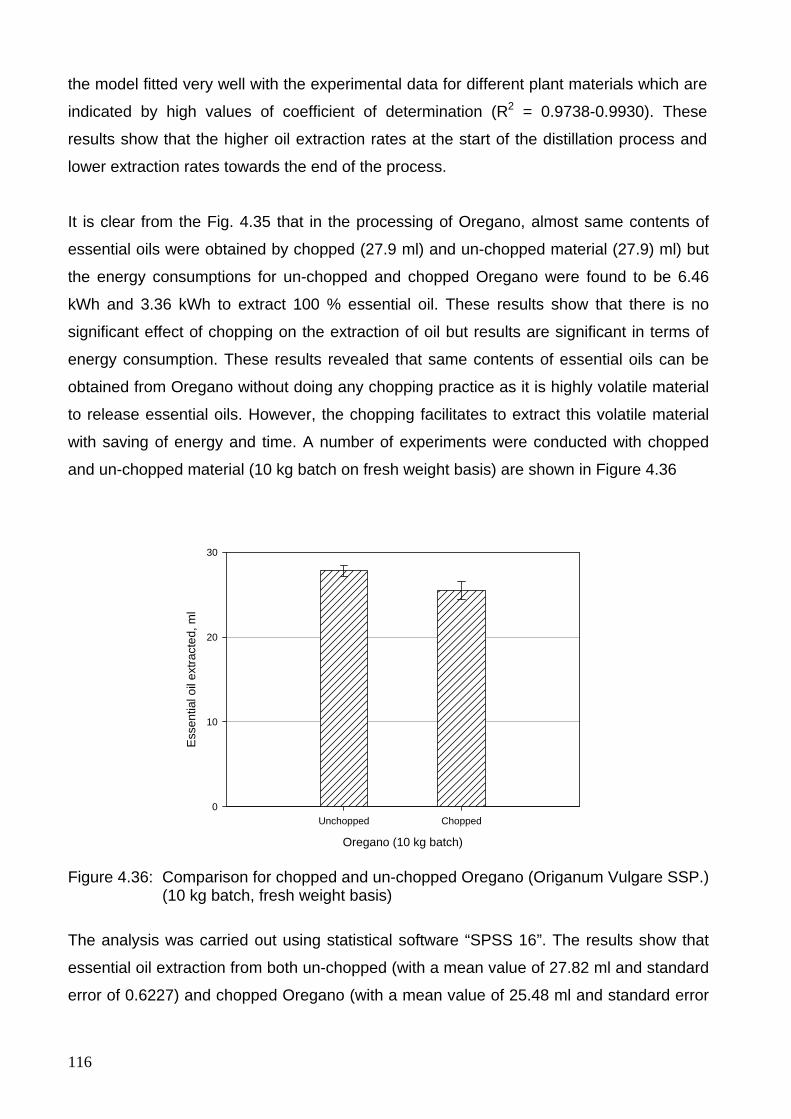
116
the model fitted very well with the experimental data for different plant materials which are
indicated by high values of coefficient of determination (R2 = 0.9738-0.9930). These
results show that the higher oil extraction rates at the start of the distillation process and
lower extraction rates towards the end of the process.
It is clear from the Fig. 4.35 that in the processing of Oregano, almost same contents of
essential oils were obtained by chopped (27.9 ml) and un-chopped material (27.9) ml) but
the energy consumptions for un-chopped and chopped Oregano were found to be 6.46
kWh and 3.36 kWh to extract 100 % essential oil. These results show that there is no
significant effect of chopping on the extraction of oil but results are significant in terms of
energy consumption. These results revealed that same contents of essential oils can be
obtained from Oregano without doing any chopping practice as it is highly volatile material
to release essential oils. However, the chopping facilitates to extract this volatile material
with saving of energy and time. A number of experiments were conducted with chopped
and un-chopped material (10 kg batch on fresh weight basis) are shown in Figure 4.36
Oregano (10 kg batch)
Unchopped Chopped
Ess
entia
l oil
extra
cted
, ml
0
10
20
30
Figure 4.36: Comparison for chopped and un-chopped Oregano (Origanum Vulgare SSP.) (10 kg batch, fresh weight basis)
The analysis was carried out using statistical software “SPSS 16”. The results show that
essential oil extraction from both un-chopped (with a mean value of 27.82 ml and standard
error of 0.6227) and chopped Oregano (with a mean value of 25.48 ml and standard error
117
of 1.10905) gave non-significant results at 5 % level of significance. These results show
that chopping of Oregano has no significant effect on the oil extraction.
4.10.3 Cloves (Eugenia caryophyllata) Cloves (Eugenia caryophyllata) are the aromatic dried flower buds of a tree in the family
Myrtaceae. Cloves are native to Indonesia and used as a spice in cuisines all over the
world. Cloves are now harvested primarily in Indonesia, Madagascar, Zanzibar, Pakistan,
Sri Lanka and India. The clove tree is an evergreen which grows to a height ranging from
8-12 m, having large square leaves and sanguine flowers in numerous groups of terminal
clusters. The flower buds are at first of a pale color and gradually become green, after
which they develop into a bright red, when they are ready for collecting. Cloves are
harvested when 1.5–2 cm long, and consist of a long calyx, terminating in four spreading
sepals, and four unopened petals which form a small ball in the centre. Cloves are used as
a carminative, to increase hydrochloric acid in the stomach and to improve peristalsis.
Cloves are also said to be a natural anthelmintic. The essential oil is used in aromatherapy
when stimulation and warming are needed, especially for digestive problems. Topical
application over the stomach or abdomen are said to warm the digestive tract. Clove oil,
applied to a cavity in a decayed tooth, also relieves toothache. It also helps to decrease
infection in the teeth due to its antiseptic properties.
In Chinese medicine cloves or ding xiang are considered acrid, warm and aromatic,
entering the kidney, spleen and stomach meridians, and are notable in their ability to warm
the middle, direct stomach qi downward, to treat hiccough and to fortify the kidney yang
(Bensky et al., 2004). Clove oil is used in various skin disorders like acne, pimples etc. It is
also used in severe burns, skin irritations and to reduce the sensitiveness of skin. It is used
as a tea and topically as oil for hypotonic muscles, including for multiple sclerosis. Western
studies have supported the use of cloves and clove oil for dental pain. However, studies to
determine its effectiveness for fever reduction, as a mosquito repellent and to prevent
premature ejaculation have been inconclusive. Cloves are traditionally used in winter to
help warm the body. Cloves warm the spleen and stomach. Cloves are used for nausea,
vomiting and hiccupping due to Cold. Cloves warm the kidneys. They are used for lumber
aches. The normal doses are 1-3 gram a day. Cloves are not recommended to use when
there are heat symptoms and Yin deficiency (Chmelik, 1999).

118
Water distillation is generally used to extract the essential oils of the dried or powdered
plant material, that is, spice powders, ground woody plants like cinnamon bark as well as
some flowers such as rose and orange and very tough material such as roots, woods, or
nuts. During the boiling process, the volatile component of the plant material is mostly
extracted at temperature just below 100 °C by diffusion mechanism (Öztekin & Martinov,
2007).
The distillation experiments with cloves were conducted by using the water distillation. For
this purpose, 20 kg of water was filled during distillation experiments and additional water
was used to make up the level of the distillation tank from the heat recovery by condenser.
The cloves were dipped into it for 2-3 hours prior to the start of the experiment so that all
oil contents can easily be extracted from the dried material. When distilling dry material,
pre soaking has been found to increase the yields, and to reduce the time required for
completion the distillation (Dürbeck, 1997). Thereafter distillation process is started. In
case of dry spices, the lower quantities of the plant material are taken so that it should be
dipped in water easily. The essential oil extraction against heat energy by solar distillation
system is shown in figure 4.37
Heat energy, kWh
0 2 4 6 8
Ess
entia
l oil
extra
cted
, ml
0
10
20
30
40
50
Observed valuesRegression line
Figure 4.37: Experimental results for the essential oils extracted against different heat energy during solar distillation of Cloves (0.8 kg)
It is evident from Fig. 4.37 that the oil extraction rate is slower at the start, then becomes
faster and at the end also becomes slower. In this experiment, 0.8 kg of the cloves were
used and 44 ml of the oil were extracted and the process consumed 7.74 kWh total heat
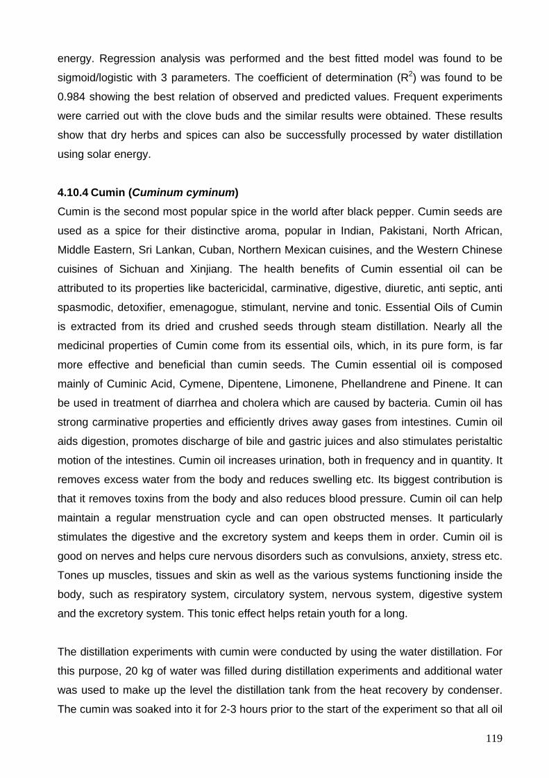
119
energy. Regression analysis was performed and the best fitted model was found to be
sigmoid/logistic with 3 parameters. The coefficient of determination (R2) was found to be
0.984 showing the best relation of observed and predicted values. Frequent experiments
were carried out with the clove buds and the similar results were obtained. These results
show that dry herbs and spices can also be successfully processed by water distillation
using solar energy.
4.10.4 Cumin (Cuminum cyminum) Cumin is the second most popular spice in the world after black pepper. Cumin seeds are
used as a spice for their distinctive aroma, popular in Indian, Pakistani, North African,
Middle Eastern, Sri Lankan, Cuban, Northern Mexican cuisines, and the Western Chinese
cuisines of Sichuan and Xinjiang. The health benefits of Cumin essential oil can be
attributed to its properties like bactericidal, carminative, digestive, diuretic, anti septic, anti
spasmodic, detoxifier, emenagogue, stimulant, nervine and tonic. Essential Oils of Cumin
is extracted from its dried and crushed seeds through steam distillation. Nearly all the
medicinal properties of Cumin come from its essential oils, which, in its pure form, is far
more effective and beneficial than cumin seeds. The Cumin essential oil is composed
mainly of Cuminic Acid, Cymene, Dipentene, Limonene, Phellandrene and Pinene. It can
be used in treatment of diarrhea and cholera which are caused by bacteria. Cumin oil has
strong carminative properties and efficiently drives away gases from intestines. Cumin oil
aids digestion, promotes discharge of bile and gastric juices and also stimulates peristaltic
motion of the intestines. Cumin oil increases urination, both in frequency and in quantity. It
removes excess water from the body and reduces swelling etc. Its biggest contribution is
that it removes toxins from the body and also reduces blood pressure. Cumin oil can help
maintain a regular menstruation cycle and can open obstructed menses. It particularly
stimulates the digestive and the excretory system and keeps them in order. Cumin oil is
good on nerves and helps cure nervous disorders such as convulsions, anxiety, stress etc.
Tones up muscles, tissues and skin as well as the various systems functioning inside the
body, such as respiratory system, circulatory system, nervous system, digestive system
and the excretory system. This tonic effect helps retain youth for a long.
The distillation experiments with cumin were conducted by using the water distillation. For
this purpose, 20 kg of water was filled during distillation experiments and additional water
was used to make up the level the distillation tank from the heat recovery by condenser.
The cumin was soaked into it for 2-3 hours prior to the start of the experiment so that all oil
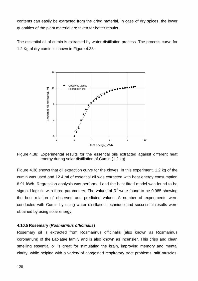
120
contents can easily be extracted from the dried material. In case of dry spices, the lower
quantities of the plant material are taken for better results.
The essential oil of cumin is extracted by water distillation process. The process curve for
1.2 Kg of dry cumin is shown in Figure 4.38.
Heat energy, kWh
0 2 4 6 8 10
Ess
entia
l oil
extra
cted
, ml
0
4
8
12
16
Observed valuesRegression line
Figure 4.38: Experimental results for the essential oils extracted against different heat energy during solar distillation of Cumin (1.2 kg)
Figure 4.38 shows that oil extraction curve for the cloves. In this experiment, 1.2 kg of the
cumin was used and 12.4 ml of essential oil was extracted with heat energy consumption
8.91 kWh. Regression analysis was performed and the best fitted model was found to be
sigmoid logistic with three parameters. The values of R2 were found to be 0.985 showing
the best relation of observed and predicted values. A number of experiments were
conducted with Cumin by using water distillation technique and successful results were
obtained by using solar energy.
4.10.5 Rosemary (Rosmarinus officinalis) Rosemary oil is extracted from Rosmarinus officinalis (also known as Rosmarinus
coronarium) of the Labiatae family and is also known as incensier. This crisp and clean
smelling essential oil is great for stimulating the brain, improving memory and mental
clarity, while helping with a variety of congested respiratory tract problems, stiff muscles,
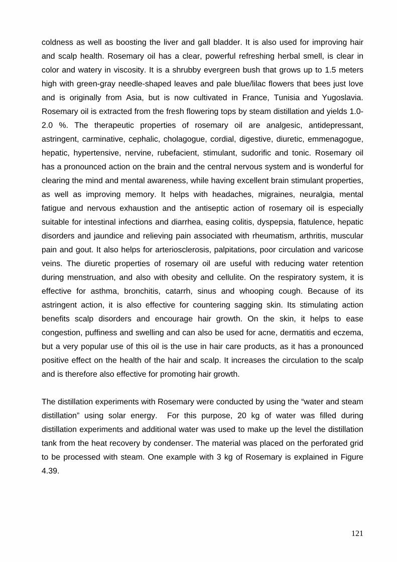
121
coldness as well as boosting the liver and gall bladder. It is also used for improving hair
and scalp health. Rosemary oil has a clear, powerful refreshing herbal smell, is clear in
color and watery in viscosity. It is a shrubby evergreen bush that grows up to 1.5 meters
high with green-gray needle-shaped leaves and pale blue/lilac flowers that bees just love
and is originally from Asia, but is now cultivated in France, Tunisia and Yugoslavia.
Rosemary oil is extracted from the fresh flowering tops by steam distillation and yields 1.0-
2.0 %. The therapeutic properties of rosemary oil are analgesic, antidepressant,
astringent, carminative, cephalic, cholagogue, cordial, digestive, diuretic, emmenagogue,
hepatic, hypertensive, nervine, rubefacient, stimulant, sudorific and tonic. Rosemary oil
has a pronounced action on the brain and the central nervous system and is wonderful for
clearing the mind and mental awareness, while having excellent brain stimulant properties,
as well as improving memory. It helps with headaches, migraines, neuralgia, mental
fatigue and nervous exhaustion and the antiseptic action of rosemary oil is especially
suitable for intestinal infections and diarrhea, easing colitis, dyspepsia, flatulence, hepatic
disorders and jaundice and relieving pain associated with rheumatism, arthritis, muscular
pain and gout. It also helps for arteriosclerosis, palpitations, poor circulation and varicose
veins. The diuretic properties of rosemary oil are useful with reducing water retention
during menstruation, and also with obesity and cellulite. On the respiratory system, it is
effective for asthma, bronchitis, catarrh, sinus and whooping cough. Because of its
astringent action, it is also effective for countering sagging skin. Its stimulating action
benefits scalp disorders and encourage hair growth. On the skin, it helps to ease
congestion, puffiness and swelling and can also be used for acne, dermatitis and eczema,
but a very popular use of this oil is the use in hair care products, as it has a pronounced
positive effect on the health of the hair and scalp. It increases the circulation to the scalp
and is therefore also effective for promoting hair growth.
The distillation experiments with Rosemary were conducted by using the “water and steam
distillation” using solar energy. For this purpose, 20 kg of water was filled during
distillation experiments and additional water was used to make up the level the distillation
tank from the heat recovery by condenser. The material was placed on the perforated grid
to be processed with steam. One example with 3 kg of Rosemary is explained in Figure
4.39.
122
Heat energy, kWh
0 1 2 3 4 5
Ess
entia
l oil
extra
cted
, ml
0
1
2
3
4
5
Observed valuesRegression line
Figure 4.39: Experimental results for the essential oils extracted against different heat energy during solar distillation of Rosemary (3 kg batch)
Figure 4.39 shows that oil extraction curve for rosemary with steam distillation. In this
experiment, 3 kg of the Rosemary and 4.6 ml of the oil was extracted against energy of
4.038 kWh. Regression analysis was performed and the best fitted model was found to be
sigmoid logistic with 3 degrees. The coefficient of determination (R2) was found to be
0.981 showing the best relation of observed and predicted values.
4.10.6 Fennel (Foeniculum valgure Mill.) Seeds (fruits) are used to flavor liqueurs, vinegars, breads, pastries, candies and pickles.
Leaves and stems occasionally serve as vegetable, salad, or Potherb. The herb has long
been an important adjunct for cooking with strong fish. Oil is used in culinary articles,
cordials, and toilet articles. The oil can be used to protect the stored fruits and vegetables
against infection by pathogenic fungi. It is reported to be abortifacient, anodyne,
aphrodisiac, balsamic, cardiotonic, carminative, diaphoretic, digestive, emmenagogue,
expectorant, lactogogue, pectoral, restorative, stimulant, stomachic, tonic, and vermicide.
The fennel is a folk remedy for aerophagia, amenorrea, hernia, nausea, nephrosis,
parturition, snakebite, sore, spasm, splenosis, stomachache, strangury, tenesmus,
toothache, and virility. Fennel juice was once a popular cough remedy. The oil is
recommended for hookworm. Lea are said to be diuretic, roots purgative, and oil
carminative and vermicidal. Resies remaining after oil extraction contain 14 to 22 %
protein and 12 to 18.5 % fat. Fruits contain 1.5 to 3.0 % essential oils and 9 to 21 % fatty
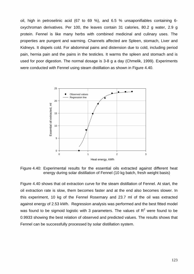
123
oil, high in petroselinic acid (67 to 69 %), and 6.5 % unsaponifiables containing 6-
oxychroman derivatives. Per 100, the leaves contain 31 calories, 80.2 g water, 2.9 g
protein. Fennel is like many herbs with combined medicinal and culinary uses. The
properties are pungent and warming. Channels affected are Spleen, stomach, Liver and
Kidneys. It dispels cold. For abdominal pains and distension due to cold, including period
pain, hernia pain and the pains in the testicles. It warms the spleen and stomach and is
used for poor digestion. The normal dosage is 3-8 g a day (Chmelik, 1999). Experiments
were conducted with Fennel using steam distillation as shown in Figure 4.40.
Heat energy, kWh
0 1 2 3
Ess
entia
l oil
extra
cted
, ml
0
5
10
15
20
25
Observed valuesRegression line
Figure 4.40: Experimental results for the essential oils extracted against different heat energy during solar distillation of Fennel (10 kg batch, fresh weight basis)
Figure 4.40 shows that oil extraction curve for the steam distillation of Fennel. At start, the
oil extraction rate is slow, them becomes faster and at the end also becomes slower. In
this experiment, 10 kg of the Fennel Rosemary and 23.7 ml of the oil was extracted
against energy of 2.53 kWh. Regression analysis was performed and the best fitted model
was found to be sigmoid logistic with 3 parameters. The values of R2 were found to be
0.9933 showing the best relation of observed and predicted values. The results shows that
Fennel can be successfully processed by solar distillation system.
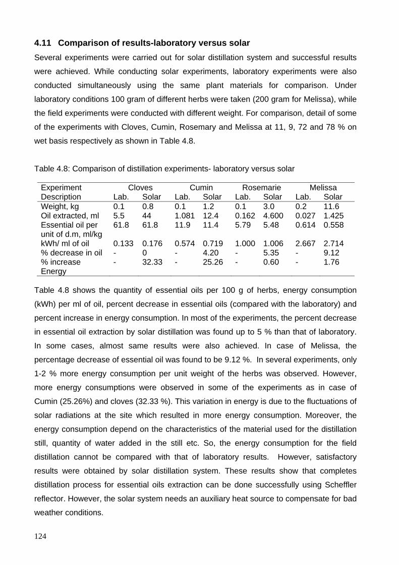
124
4.11 Comparison of results-laboratory versus solar Several experiments were carried out for solar distillation system and successful results
were achieved. While conducting solar experiments, laboratory experiments were also
conducted simultaneously using the same plant materials for comparison. Under
laboratory conditions 100 gram of different herbs were taken (200 gram for Melissa), while
the field experiments were conducted with different weight. For comparison, detail of some
of the experiments with Cloves, Cumin, Rosemary and Melissa at 11, 9, 72 and 78 % on
wet basis respectively as shown in Table 4.8.
Table 4.8: Comparison of distillation experiments- laboratory versus solar
Experiment Description
Cloves Cumin Rosemarie Melissa Lab. Solar Lab. Solar Lab. Solar Lab. Solar
Weight, kg 0.1 0.8 0.1 1.2 0.1 3.0 0.2 11.6 Oil extracted, ml 5.5 44 1.081 12.4 0.162 4.600 0.027 1.425 Essential oil per unit of d.m, ml/kg
61.8 61.8 11.9 11.4 5.79 5.48 0.614 0.558
kWh/ ml of oil 0.133 0.176 0.574 0.719 1.000 1.006 2.667 2.714 % decrease in oil - 0 - 4.20 - 5.35 - 9.12 % increase Energy
- 32.33 - 25.26 - 0.60 - 1.76
Table 4.8 shows the quantity of essential oils per 100 g of herbs, energy consumption
(kWh) per ml of oil, percent decrease in essential oils (compared with the laboratory) and
percent increase in energy consumption. In most of the experiments, the percent decrease
in essential oil extraction by solar distillation was found up to 5 % than that of laboratory.
In some cases, almost same results were also achieved. In case of Melissa, the
percentage decrease of essential oil was found to be 9.12 %. In several experiments, only
1-2 % more energy consumption per unit weight of the herbs was observed. However,
more energy consumptions were observed in some of the experiments as in case of
Cumin (25.26%) and cloves (32.33 %). This variation in energy is due to the fluctuations of
solar radiations at the site which resulted in more energy consumption. Moreover, the
energy consumption depend on the characteristics of the material used for the distillation
still, quantity of water added in the still etc. So, the energy consumption for the field
distillation cannot be compared with that of laboratory results. However, satisfactory
results were obtained by solar distillation system. These results show that completes
distillation process for essential oils extraction can be done successfully using Scheffler
reflector. However, the solar system needs an auxiliary heat source to compensate for bad
weather conditions.
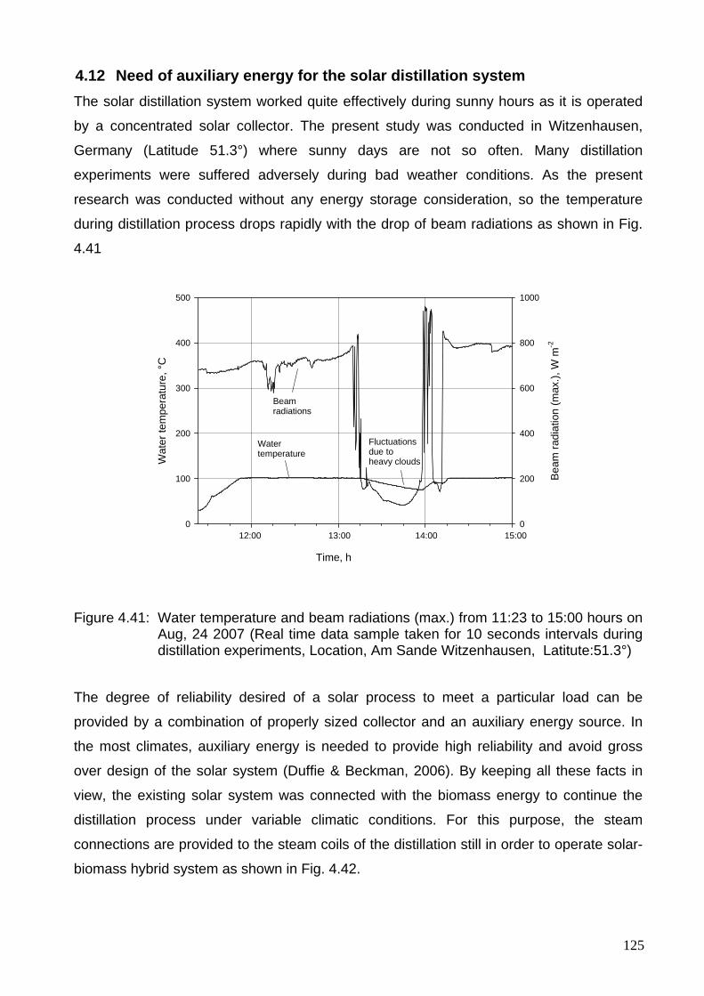
125
4.12 Need of auxiliary energy for the solar distillation system The solar distillation system worked quite effectively during sunny hours as it is operated
by a concentrated solar collector. The present study was conducted in Witzenhausen,
Germany (Latitude 51.3°) where sunny days are not so often. Many distillation
experiments were suffered adversely during bad weather conditions. As the present
research was conducted without any energy storage consideration, so the temperature
during distillation process drops rapidly with the drop of beam radiations as shown in Fig.
4.41
Time, hB
eam
radi
atio
n (m
ax.),
W m
-2
0
200
400
600
800
1000
Wat
er te
mpe
ratu
re, °
C
0
100
200
300
400
500
12:00 13:00 14:00 15:00
Beam radiations
Water temperature
Fluctuationsdue toheavy clouds
Figure 4.41: Water temperature and beam radiations (max.) from 11:23 to 15:00 hours on Aug, 24 2007 (Real time data sample taken for 10 seconds intervals during distillation experiments, Location, Am Sande Witzenhausen, Latitute:51.3°)
The degree of reliability desired of a solar process to meet a particular load can be
provided by a combination of properly sized collector and an auxiliary energy source. In
the most climates, auxiliary energy is needed to provide high reliability and avoid gross
over design of the solar system (Duffie & Beckman, 2006). By keeping all these facts in
view, the existing solar system was connected with the biomass energy to continue the
distillation process under variable climatic conditions. For this purpose, the steam
connections are provided to the steam coils of the distillation still in order to operate solar-
biomass hybrid system as shown in Fig. 4.42.
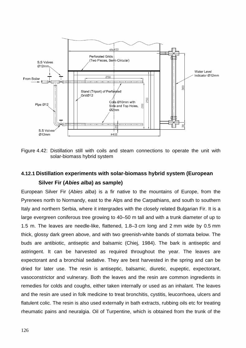
126
Figure 4.42: Distillation still with coils and steam connections to operate the unit with solar-biomass hybrid system
4.12.1 Distillation experiments with solar-biomass hybrid system (European Silver Fir (Abies alba) as sample)
European Silver Fir (Abies alba) is a fir native to the mountains of Europe, from the
Pyrenees north to Normandy, east to the Alps and the Carpathians, and south to southern
Italy and northern Serbia, where it intergrades with the closely related Bulgarian Fir. It is a
large evergreen coniferous tree growing to 40–50 m tall and with a trunk diameter of up to
1.5 m. The leaves are needle-like, flattened, 1.8–3 cm long and 2 mm wide by 0.5 mm
thick, glossy dark green above, and with two greenish-white bands of stomata below. The
buds are antibiotic, antiseptic and balsamic (Chiej, 1984). The bark is antiseptic and
astringent. It can be harvested as required throughout the year. The leaves are
expectorant and a bronchial sedative. They are best harvested in the spring and can be
dried for later use. The resin is antiseptic, balsamic, diuretic, eupeptic, expectorant,
vasoconstrictor and vulnerary. Both the leaves and the resin are common ingredients in
remedies for colds and coughs, either taken internally or used as an inhalant. The leaves
and the resin are used in folk medicine to treat bronchitis, cystitis, leucorrhoea, ulcers and
flatulent colic. The resin is also used externally in bath extracts, rubbing oils etc for treating
rheumatic pains and neuralgia. Oil of Turpentine, which is obtained from the trunk of the
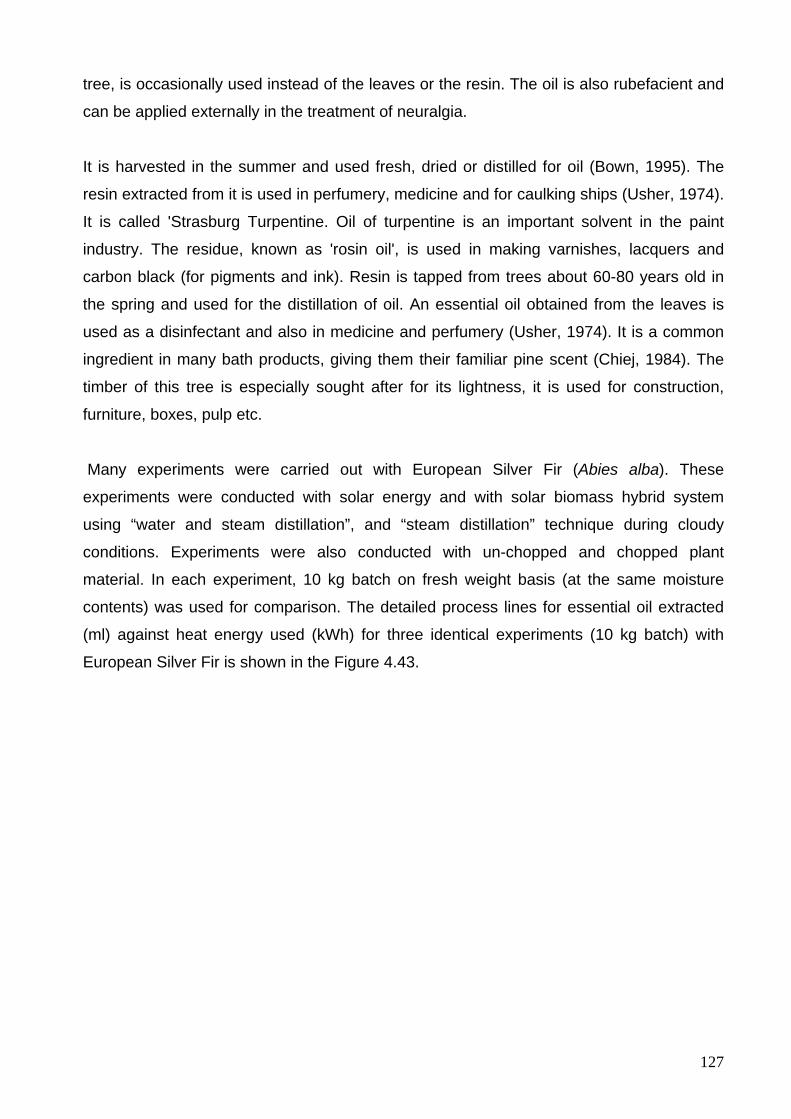
127
tree, is occasionally used instead of the leaves or the resin. The oil is also rubefacient and
can be applied externally in the treatment of neuralgia.
It is harvested in the summer and used fresh, dried or distilled for oil (Bown, 1995). The
resin extracted from it is used in perfumery, medicine and for caulking ships (Usher, 1974).
It is called 'Strasburg Turpentine. Oil of turpentine is an important solvent in the paint
industry. The residue, known as 'rosin oil', is used in making varnishes, lacquers and
carbon black (for pigments and ink). Resin is tapped from trees about 60-80 years old in
the spring and used for the distillation of oil. An essential oil obtained from the leaves is
used as a disinfectant and also in medicine and perfumery (Usher, 1974). It is a common
ingredient in many bath products, giving them their familiar pine scent (Chiej, 1984). The
timber of this tree is especially sought after for its lightness, it is used for construction,
furniture, boxes, pulp etc.
Many experiments were carried out with European Silver Fir (Abies alba). These
experiments were conducted with solar energy and with solar biomass hybrid system
using “water and steam distillation”, and “steam distillation” technique during cloudy
conditions. Experiments were also conducted with un-chopped and chopped plant
material. In each experiment, 10 kg batch on fresh weight basis (at the same moisture
contents) was used for comparison. The detailed process lines for essential oil extracted
(ml) against heat energy used (kWh) for three identical experiments (10 kg batch) with
European Silver Fir is shown in the Figure 4.43.
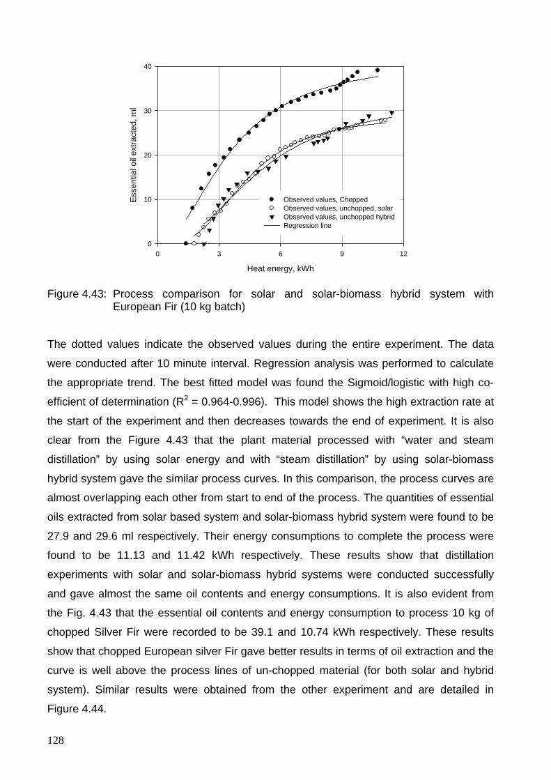
128
Heat energy, kWh
0 3 6 9 12
Ess
entia
l oil
extra
cted
, ml
0
10
20
30
40
Observed values, ChoppedObserved values, unchopped, solarObserved values, unchopped hybridRegression line
Figure 4.43: Process comparison for solar and solar-biomass hybrid system with European Fir (10 kg batch)
The dotted values indicate the observed values during the entire experiment. The data
were conducted after 10 minute interval. Regression analysis was performed to calculate
the appropriate trend. The best fitted model was found the Sigmoid/logistic with high co-
efficient of determination (R2 = 0.964-0.996). This model shows the high extraction rate at
the start of the experiment and then decreases towards the end of experiment. It is also
clear from the Figure 4.43 that the plant material processed with “water and steam
distillation” by using solar energy and with “steam distillation” by using solar-biomass
hybrid system gave the similar process curves. In this comparison, the process curves are
almost overlapping each other from start to end of the process. The quantities of essential
oils extracted from solar based system and solar-biomass hybrid system were found to be
27.9 and 29.6 ml respectively. Their energy consumptions to complete the process were
found to be 11.13 and 11.42 kWh respectively. These results show that distillation
experiments with solar and solar-biomass hybrid systems were conducted successfully
and gave almost the same oil contents and energy consumptions. It is also evident from
the Fig. 4.43 that the essential oil contents and energy consumption to process 10 kg of
chopped Silver Fir were recorded to be 39.1 and 10.74 kWh respectively. These results
show that chopped European silver Fir gave better results in terms of oil extraction and the
curve is well above the process lines of un-chopped material (for both solar and hybrid
system). Similar results were obtained from the other experiment and are detailed in
Figure 4.44.
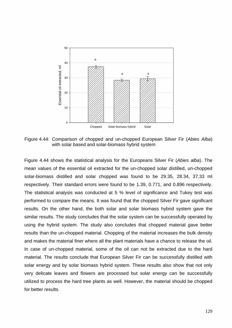
129
Chopped Solar-biomass hybrid Solar
Esse
ntia
l oil
extra
cted
, ml
0
10
20
30
40
50
b
a a
Figure 4.44: Comparison of chopped and un-chopped European Silver Fir (Abies Alba) with solar based and solar-biomass hybrid system
Figure 4.44 shows the statistical analysis for the Europeans Silver Fir (Abies alba). The
mean values of the essential oil extracted for the un-chopped solar distilled, un-chopped
solar-biomass distilled and solar chopped was found to be 29.35, 28.34, 37.33 ml
respectively. Their standard errors were found to be 1.39, 0.771, and 0.896 respectively.
The statistical analysis was conducted at 5 % level of significance and Tukey test was
performed to compare the means. It was found that the chopped Silver Fir gave significant
results. On the other hand, the both solar and solar biomass hybrid system gave the
similar results. The study concludes that the solar system can be successfully operated by
using the hybrid system. The study also concludes that chopped material gave better
results than the un-chopped material. Chopping of the material increases the bulk density
and makes the material finer where all the plant materials have a chance to release the oil.
In case of un-chopped material, some of the oil can not be extracted due to the hard
material. The results conclude that European Silver Fir can be successfully distilled with
solar energy and by solar biomass hybrid system. These results also show that not only
very delicate leaves and flowers are processed but solar energy can be successfully
utilized to process the hard tree plants as well. However, the material should be chopped
for better results.
130
Several experiments were carried out during adverse climatic conditions using solar
distillation system integrated with biomass energy. During these experiments, the
distillation still was filled with water to produce steam by reflected beam radiations on the
still bottom and the extra energy was taken from the biomass boiler. The experiments were
conducted with different plant material like Melissa, Peppermint, Lavender, European
Silver Fir etc (10 kg batch) are shown in the Figure 4.45.
Plant materials
Melissa Peppermint Silver Fir
Ess
entia
l oils
ext
ract
ed, m
l
0
10
20
30
40
Figure 4.45: Results of solar-biomass hybrid distillation system for Peppermint, Melissa, European Silver Fir (10 kg batch)
The average amount of oil extracted for Peppermint, Melissa and European Silver Fir were
21.46, 1.317 and 29.3 ml. The energy ratio of biomass to solar energy was varied from 0.3
to 0.5 during most of the experiments conducted by solar-biomass hybrid distillation
system. The results reveal that biomass energy can be successfully utilized in the solar
distillation system to operate the distillation experiments during adverse climatic
conditions.
In order to recover energy from the steam, the quantity of inlet cold water to the condenser
is controlled to get maximum outlet temperature. This water is stored and recycled to
make up any deficiency in the distillation still during experiments as well as to recharge the
distillation unit for the next batch. The schematic diagram for solar-biomass hybrid
distillation system with heat recovery unit is shown in Figure 4.46
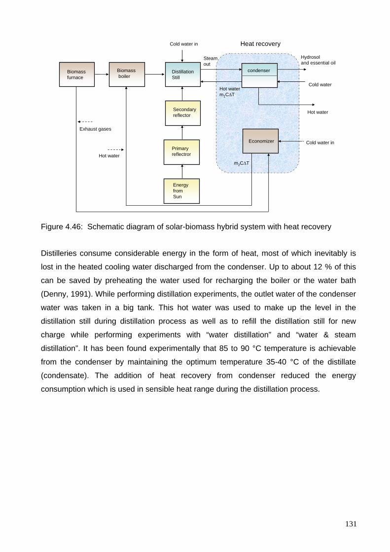
131
Cold water
Steam out
Energy from Sun
Hydrosol and essential oil
Secondaryreflector
DistillationStill
Primaryreflectror
Heat recoveryCold water in
Cold water in
m2C∆T
Exhaust gases
condenserBiomassboiler
Biomassfurnace
Hot water
Hot water
Hot water m1C∆T
Economizer
Figure 4.46: Schematic diagram of solar-biomass hybrid system with heat recovery
Distilleries consume considerable energy in the form of heat, most of which inevitably is
lost in the heated cooling water discharged from the condenser. Up to about 12 % of this
can be saved by preheating the water used for recharging the boiler or the water bath
(Denny, 1991). While performing distillation experiments, the outlet water of the condenser
water was taken in a big tank. This hot water was used to make up the level in the
distillation still during distillation process as well as to refill the distillation still for new
charge while performing experiments with “water distillation” and “water & steam
distillation”. It has been found experimentally that 85 to 90 °C temperature is achievable
from the condenser by maintaining the optimum temperature 35-40 °C of the distillate
(condensate). The addition of heat recovery from condenser reduced the energy
consumption which is used in sensible heat range during the distillation process.
132
5 Overall discussion
The design, development, experimental results of a solar distillation system have been
presented. The main components of solar distillation system are primary reflector,
secondary reflector, distillation still, condenser, and Florentine vessels. Solar distillation
system was designed as a fixed installation and all parts of the reflector stand were
prepared and assembled with respect to the latitude of Witzenhausen (51.3°). The
complete solar based distillation system was constructed in the Agricultural Engineering
workshop, University of Kassel, Witzenhausen, Germany.
Many research papers were reviewed on production, uses, drying and processing of
medicinal and other plant materials. Design and develop of different types of distillation
plants were also studied for the processing of medicinal and aromatic plants using the
conventional fuels. A large number of papers are available on different innovative solar
collectors in the medium temperature range. In the light of the research work conducted,
the present research was focused to integrate the standard distillation techniques with the
solar energy for the processing of medicinal and aromatic plants in such a way that it can
be applicable for the on-farm processing of medicinal and aromatic plants by using a solar
based distillation system.
Laboratory experiments were conducted to investigate the optimal thermal and physical
parameters. Heat energy consumptions to process 100 grams of Cloves buds, Fennel,
Cumin, Melissa, Patchouli, Cassia, Orange barks, Lavender and Peppermint were ranged
between 0.163 and 0.718 kWh. This energy span is remarkable showing that different
plant materials have different energy consumptions per unit weight of plant material during
the distillation process. Laboratory results also concluded that fresh herbs needed short
duration for processing and were less energy consuming. The study reveals that the on-
farm processing of fresh medicinal and aromatic plants is necessary for functional and
economic reasons. From the recorded data, energy consumptions to extract one ml of the
oil were calculated. The heat energy consumptions to extract one ml from Cloves buds,
Fennel, Cumin, Melissa, Patchouli, Cassia, Orange barks, Lavender, Peppermint were
ranged between 0.133 and 2.807 kWh respectively. The laboratory experiments were
carried out to extract the full contents of the plant material. However, the energy
consumptions of the field distillation stills cannot be compared with that of the laboratory
as they differ in material, geometry and environmental conditions. Moreover, amount of
133
water taken per unit mass varies in both types of distillation units. The study concludes
that the laboratory setup is only useful to compare the oil extraction but cannot be used for
energy comparison. Under laboratory condition, 0.2 kg of different plant materials were
processed successfully in 2 liter glass boiler. For the field experiments, 100 liter capacity
distillation still was fabricated with 400 mm diameter and 1210 mm column height to
process 10 kg of different plant materials. Thereafter a solar system was selected which
can provide the required power to conduct different distillation experiments.
Next step of the study was the selection of an efficient solar collector which can provide
the required temperature range to conduct different distillation experiments successfully.
The solar system can also facilitate “water distillation” and “water and steam distillation” by
a continuous and uniform heat distribution on the entire circumference of the distillation
still. The distillation still should be easy to charge and clean when integrated with the solar
system. The options of vacuum tube collectors with integrated circuits were also studied.
These reflectors are more efficient and can provide the required range of the temperature
but can not meet the required heat distribution at the bottom of the distillation still.
Selection of a Scheffler reflector with secondary reflector arrangement facilitates to
conduct different distillation experiments by providing the heat at the bottom like
conventional distillation system. In the present study, an 8 m2 Scheffler fixed focus
concentrator was selected for distillation experiments. Up to now, no mathematical
description of the design process of a Scheffler reflector has been done. The study
explains the design principle and construction detail of an 8 m2 Scheffler fixed focus
concentrator. The results have proved mathematically that it is possible to construct a
concentrator that can provide fixed focus for all the days of the year. The slope and y-
intercepts for the 8 m2 surface area Scheffler reflector with respect to equinox (solar
declination = 0) are calculated to be 0.17447 and 0 respectively. The slopes of the
parabola equations for two extreme position of summer (solar declination = +23.5) and
winter (solar declination = -23.5) in the northern hemisphere (standing reflectors) are
calculated to be 0.28123, and 0.12736 respectively. The y-intercepts of the parabola
curves for summer and winter are calculated to be 0.54394, and -0.53004 respectively. By
comparing with the equinox parabola curve, the summer parabola is found to be smaller in
size and uses the top part of the parabola curve, while the winter parabola is bigger in size
and uses the lower part of a parabola curve to give the fixed focus. In conclusion, the
parabola equations on June 21 and December 21 in the southern hemisphere are found to
be the same as the parabola equations on December 21 and June 21 in the northern
134
hemisphere respectively for the standing reflectors. In laying reflectors, the parabola
equations for the northern hemisphere are found to be the same as the parabola equations
for the southern hemisphere (standing reflectors). Similarly, the parabola equations for
laying reflectors in the southern hemisphere are the same as the parabola equations in the
northern hemisphere for standing reflectors. For this purpose, the reflector assembly is
composed of flexible crossbars and a frame to induce the required change of parabola
curves with the changing solar declination. The study also concludes that the concentrator
is to be installed at the required site by setting its axis of rotation equal to the latitude of the
site in north-south directions to make the axis of the reflector paraboloid parallel to the
beam radiations. For daily tracking, these concentrators rotate along an axis parallel to the
polar axis of the earth at an angular velocity of one revolution per day with the help of self-
tracking devices. The seasonal tracking rotates the reflector at half the solar declination
angle to induce the required change of the shape of the reflector paraboloid to track the
sun at the fixed focus. Aluminium sheets (with solar weighted reflectance of 88-91 %) from
Alcan Company Germany were used successfully for the Scheffler reflector. This material
is not available in most of the Asian and African countries. In order to construct a solar
distillation system using a Scheffler reflector economically, small plan mirror strips can also
be used. By using these mirrors, the material cost of a Scheffler reflector also becomes
significantly lowered and this technique fits to the rural areas for on-farm processing of
perishable products in most of the underdeveloped countries. Moreover, the construction
and fabrication of these reflectors are also possible in an ordinary workshop. This offers a
huge potential for its application in domestic as well as industrial configurations. These
constructional and installation procedures are applicable all over the world. Scheffler
reflector needs little maintenance and can be used for many years provided the reflectors
should be free from dirt and other weathering hazards. The main drawback of these
reflectors is that a slight inaccuracy during construction will result in poor performance of
the reflectors. In fact, the fixed focus is achieved by the combined effect of precisely
shaped profiles as well as daily and seasonal tracking accuracy. The distillation
experiments can also be carried out with other conventional concentrators which are
cheaper but more labor intensive.
Two mathematical models were also developed. First mathematical model was developed
in Matlab 7 and Microsoft Excel to calculate the required size of the Scheffler reflector. The
second model was developed to calculate the energy distribution and heat losses from
different parts of the solar distillation system which provides useful information to optimize
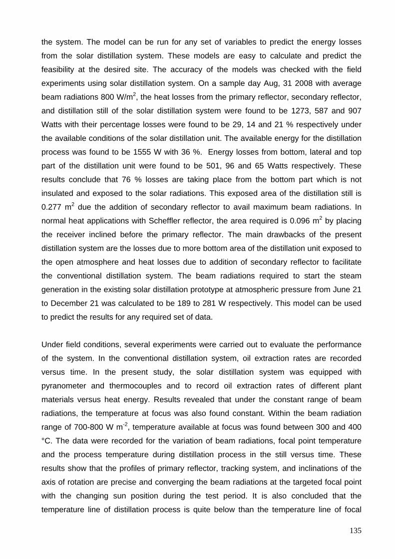
135
the system. The model can be run for any set of variables to predict the energy losses
from the solar distillation system. These models are easy to calculate and predict the
feasibility at the desired site. The accuracy of the models was checked with the field
experiments using solar distillation system. On a sample day Aug, 31 2008 with average
beam radiations 800 W/m2, the heat losses from the primary reflector, secondary reflector,
and distillation still of the solar distillation system were found to be 1273, 587 and 907
Watts with their percentage losses were found to be 29, 14 and 21 % respectively under
the available conditions of the solar distillation unit. The available energy for the distillation
process was found to be 1555 W with 36 %. Energy losses from bottom, lateral and top
part of the distillation unit were found to be 501, 96 and 65 Watts respectively. These
results conclude that 76 % losses are taking place from the bottom part which is not
insulated and exposed to the solar radiations. This exposed area of the distillation still is
0.277 m2 due the addition of secondary reflector to avail maximum beam radiations. In
normal heat applications with Scheffler reflector, the area required is 0.096 m2 by placing
the receiver inclined before the primary reflector. The main drawbacks of the present
distillation system are the losses due to more bottom area of the distillation unit exposed to
the open atmosphere and heat losses due to addition of secondary reflector to facilitate
the conventional distillation system. The beam radiations required to start the steam
generation in the existing solar distillation prototype at atmospheric pressure from June 21
to December 21 was calculated to be 189 to 281 W respectively. This model can be used
to predict the results for any required set of data.
Under field conditions, several experiments were carried out to evaluate the performance
of the system. In the conventional distillation system, oil extraction rates are recorded
versus time. In the present study, the solar distillation system was equipped with
pyranometer and thermocouples and to record oil extraction rates of different plant
materials versus heat energy. Results revealed that under the constant range of beam
radiations, the temperature at focus was also found constant. Within the beam radiation
range of 700-800 W m-2, temperature available at focus was found between 300 and 400
°C. The data were recorded for the variation of beam radiations, focal point temperature
and the process temperature during distillation process in the still versus time. These
results show that the profiles of primary reflector, tracking system, and inclinations of the
axis of rotation are precise and converging the beam radiations at the targeted focal point
with the changing sun position during the test period. It is also concluded that the
temperature line of distillation process is quite below than the temperature line of focal
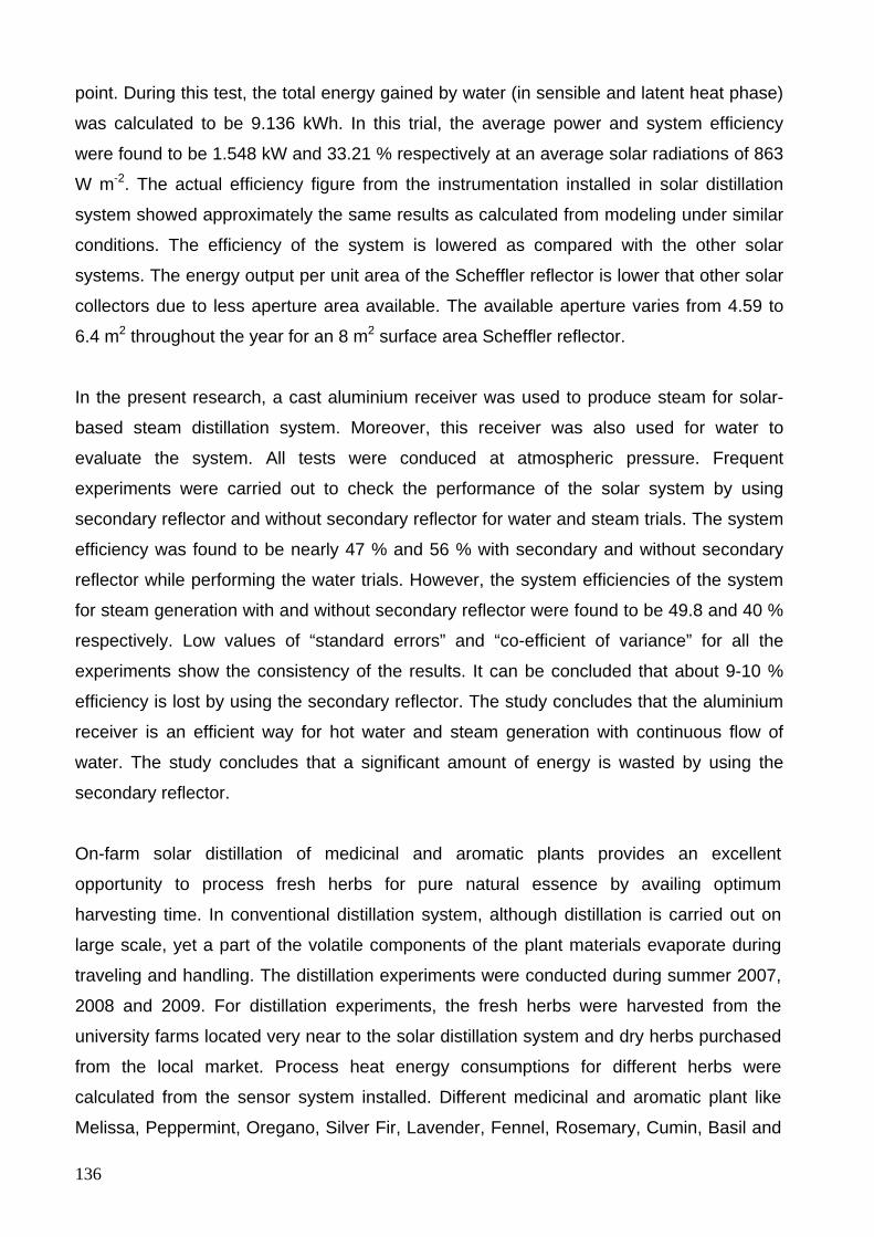
136
point. During this test, the total energy gained by water (in sensible and latent heat phase)
was calculated to be 9.136 kWh. In this trial, the average power and system efficiency
were found to be 1.548 kW and 33.21 % respectively at an average solar radiations of 863
W m-2. The actual efficiency figure from the instrumentation installed in solar distillation
system showed approximately the same results as calculated from modeling under similar
conditions. The efficiency of the system is lowered as compared with the other solar
systems. The energy output per unit area of the Scheffler reflector is lower that other solar
collectors due to less aperture area available. The available aperture varies from 4.59 to
6.4 m2 throughout the year for an 8 m2 surface area Scheffler reflector.
In the present research, a cast aluminium receiver was used to produce steam for solar-
based steam distillation system. Moreover, this receiver was also used for water to
evaluate the system. All tests were conduced at atmospheric pressure. Frequent
experiments were carried out to check the performance of the solar system by using
secondary reflector and without secondary reflector for water and steam trials. The system
efficiency was found to be nearly 47 % and 56 % with secondary and without secondary
reflector while performing the water trials. However, the system efficiencies of the system
for steam generation with and without secondary reflector were found to be 49.8 and 40 %
respectively. Low values of “standard errors” and “co-efficient of variance” for all the
experiments show the consistency of the results. It can be concluded that about 9-10 %
efficiency is lost by using the secondary reflector. The study concludes that the aluminium
receiver is an efficient way for hot water and steam generation with continuous flow of
water. The study concludes that a significant amount of energy is wasted by using the
secondary reflector.
On-farm solar distillation of medicinal and aromatic plants provides an excellent
opportunity to process fresh herbs for pure natural essence by availing optimum
harvesting time. In conventional distillation system, although distillation is carried out on
large scale, yet a part of the volatile components of the plant materials evaporate during
traveling and handling. The distillation experiments were conducted during summer 2007,
2008 and 2009. For distillation experiments, the fresh herbs were harvested from the
university farms located very near to the solar distillation system and dry herbs purchased
from the local market. Process heat energy consumptions for different herbs were
calculated from the sensor system installed. Different medicinal and aromatic plant like
Melissa, Peppermint, Oregano, Silver Fir, Lavender, Fennel, Rosemary, Cumin, Basil and
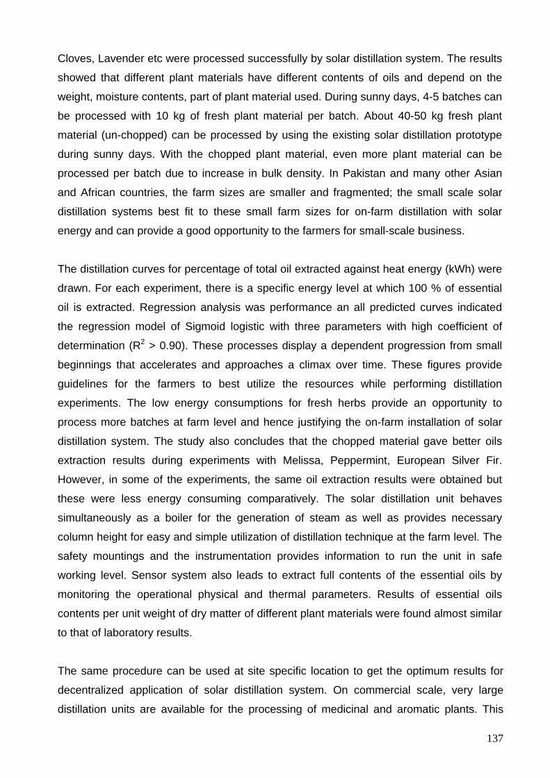
137
Cloves, Lavender etc were processed successfully by solar distillation system. The results
showed that different plant materials have different contents of oils and depend on the
weight, moisture contents, part of plant material used. During sunny days, 4-5 batches can
be processed with 10 kg of fresh plant material per batch. About 40-50 kg fresh plant
material (un-chopped) can be processed by using the existing solar distillation prototype
during sunny days. With the chopped plant material, even more plant material can be
processed per batch due to increase in bulk density. In Pakistan and many other Asian
and African countries, the farm sizes are smaller and fragmented; the small scale solar
distillation systems best fit to these small farm sizes for on-farm distillation with solar
energy and can provide a good opportunity to the farmers for small-scale business.
The distillation curves for percentage of total oil extracted against heat energy (kWh) were
drawn. For each experiment, there is a specific energy level at which 100 % of essential
oil is extracted. Regression analysis was performance an all predicted curves indicated
the regression model of Sigmoid logistic with three parameters with high coefficient of
determination (R2 > 0.90). These processes display a dependent progression from small
beginnings that accelerates and approaches a climax over time. These figures provide
guidelines for the farmers to best utilize the resources while performing distillation
experiments. The low energy consumptions for fresh herbs provide an opportunity to
process more batches at farm level and hence justifying the on-farm installation of solar
distillation system. The study also concludes that the chopped material gave better oils
extraction results during experiments with Melissa, Peppermint, European Silver Fir.
However, in some of the experiments, the same oil extraction results were obtained but
these were less energy consuming comparatively. The solar distillation unit behaves
simultaneously as a boiler for the generation of steam as well as provides necessary
column height for easy and simple utilization of distillation technique at the farm level. The
safety mountings and the instrumentation provides information to run the unit in safe
working level. Sensor system also leads to extract full contents of the essential oils by
monitoring the operational physical and thermal parameters. Results of essential oils
contents per unit weight of dry matter of different plant materials were found almost similar
to that of laboratory results.
The same procedure can be used at site specific location to get the optimum results for
decentralized application of solar distillation system. On commercial scale, very large
distillation units are available for the processing of medicinal and aromatic plants. This
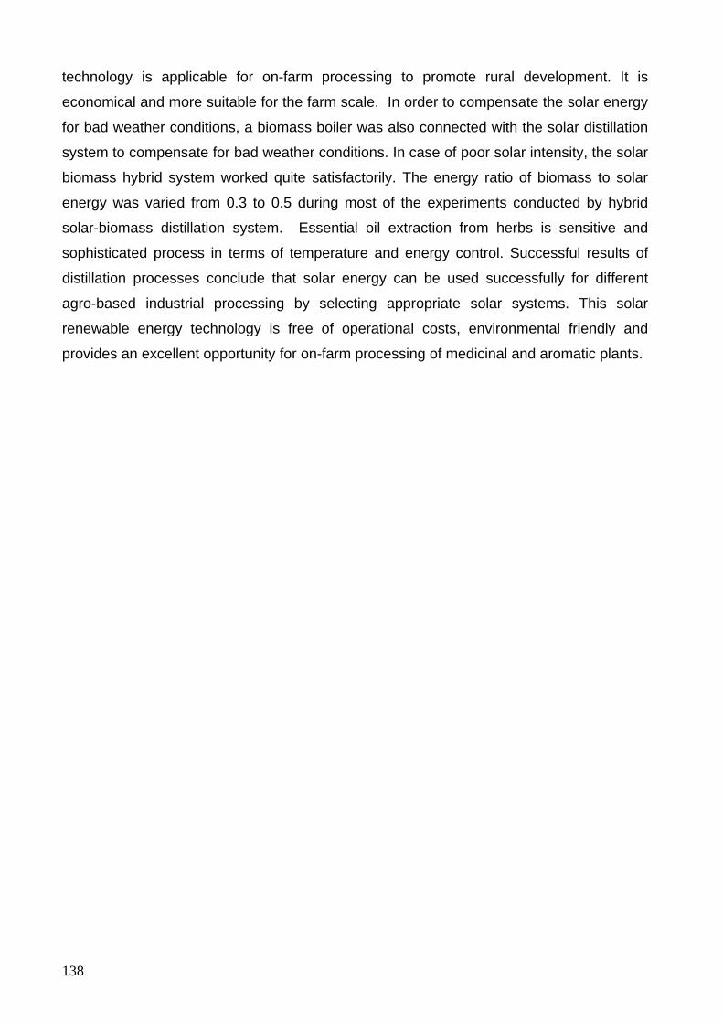
138
technology is applicable for on-farm processing to promote rural development. It is
economical and more suitable for the farm scale. In order to compensate the solar energy
for bad weather conditions, a biomass boiler was also connected with the solar distillation
system to compensate for bad weather conditions. In case of poor solar intensity, the solar
biomass hybrid system worked quite satisfactorily. The energy ratio of biomass to solar
energy was varied from 0.3 to 0.5 during most of the experiments conducted by hybrid
solar-biomass distillation system. Essential oil extraction from herbs is sensitive and
sophisticated process in terms of temperature and energy control. Successful results of
distillation processes conclude that solar energy can be used successfully for different
agro-based industrial processing by selecting appropriate solar systems. This solar
renewable energy technology is free of operational costs, environmental friendly and
provides an excellent opportunity for on-farm processing of medicinal and aromatic plants.
139
6 Outlook
In the article 4.10, results of some the distillation experiments with solar energy have been
presented. Experiments were also conducted with water and steam distillation processes
with Lavender (Lavedula L.), Basel, Calendula and other plant materials. For all
experiments, successful results were obtained. The successful results concluded that the
solar energy can be successfully used for the distillation of all kinds of medicinal and
aromatic plants. These experiments were conducted with a specific size of the distillation
still (100 liter capacity) which is capable to process 10 kg fresh plant material on fresh
weight basis (un-chopped) and 15-20 kg chopped plant material.
The main object of the research is to develop an on-farm distillation system for essential
oils extraction from different herbs and plant materials. However, provision was also given
to the solar system for the on-farm food processing. For this purpose, special food grade
pots (40 liters capacity) were used after modifying them according to the existing design of
solar system. The back plate of secondary reflector was fabricated as a removable
assembly which facilitates easy replacing of distillation still by food vessels. On the
experimental farms near solar campus, a variety of fruits (Apples, Plums, Johannesburg,
tomatoes etc) were available. Experiments were conducted for the manufacturing of jams
from Johannesburg, and plums and tomato peeling from tomato using solar energy. The
sterilization processes of the vessel and glass bottles were also carried out with solar
energy before the food processing. These products were sealed and preserved. These
food products were successfully processed by solar energy. The purpose of these trials
was to introduce the farmers about the multifunctional use of solar energy in a very simple
and easy method so that they may process their perishable products at the farm level.
140
7 Recommendations and suggestions
The current study is conducted with only one batch type distillation still. It is
recommended to use another identical distillation still to make one still always in
operation and other on charging position to best utilize the solar energy and to distill
more batches. The study also suggests a continuous type distillation system should
be used to save the heat losses and time while charging a new batch.
Laying reflectors provide an elevated focus directly on the receiver and thus need
very small area of the secondary reflector to reflect these radiations to the bottom of
distillation still. A significant amount of energy can be saved and can be used
during distillation experiments.
Out of the total losses from the distillation still, about 76 % losses are from the
bottom part exposed to the solar radiations. The green house effect should be
considered in secondary reflector to minimize these heat losses.
Heat recovery system was used intermittently for the charging of new batches and
to make up the water. It is suggested that the system should be modified to refill the
distillation still continuously.
As a solar concentrator is used for distillation experiments, these kinds of solar
based systems are best suited for the regions with high beam radiations.
The existing size of the distillation system is smaller as compared with the
conventional field distillation units. It is recommended to develop big size solar
distillation systems by using bigger size reflectors to save time and energy.
Scheffler reflectors can be constructed up to 60 m2 successfully.
The existing solar distillation system was operated at atmospheric pressure. The
system should be modified to run the distillation experiments at different pressures.
141
8 Summary Processing of medicinal and aromatic plants by distillation method is one of the agro-
based industries which lie in the medium temperature range. Essential oils extracted from
these plant materials have been used throughout the world in foods, fragrances,
perfumery, cosmetics and medicines and these oils are very expensive. With the
introduction of innovative solar collectors, it is possible to use solar energy in the medium
temperature range. The study was initiated to develop a de-centralized solar distillation
system for the processing of medicinal and aromatic plants for functional, environmental
and economic reasons. The system was installed at solar campus, University of Kassel,
Witzenhausen, Germany to avail the fresh supply of herbs. Scheffler fixed focus
concentrator (8 m2 surface area) was used for solar distillation system. The system
comprises of a primary reflector, secondary reflector, distillation still, condenser unit and
Florentine flasks. The primary reflector rotates along an axis parallel to the earth axis of
rotation and keeps the reflected beam aligned with the fixed secondary reflector as the sun
moves. The secondary reflector further reflects the beam radiation to the targeted
distillation still bottom. The distillation still was fabricated of a food grade stainless steel
vessel having 1210 mm column height, 400 mm diameter, and 2 mm thickness. Stainless
steel condenser is connected to the distillation still via a pipe. The distillation unit has
provision to operate for “water distillation” and “water and steam distillation”. The solar
distillation system is equipped with thermocouples and Pyranometer to control and
optimize the distillation processes.
During the first phase of the research, laboratory experiments were conducted to
determine the heat energy required per unit weight of different plant materials. Scheffler
fixed focus concentrator was selected for the processing of medicinal and aromatic plants.
A mathematical procedure has been explained to calculate the parabola equations for an 8
m2 surface area Scheffler reflector for all the days of the year in the northern and southern
hemisphere. The construction, installation and tracking details of the solar distillations
system are also explained in the manuscript.
Two mathematical models were developed in Matlab and Microsoft Excel. First model is
used to calculate the required size of the Scheffler reflector and the second model is
applied to predict the energy distribution and heat losses from the solar distillation system.
Under field experiments, several experiments were carried out to evaluate the
142
performance of the system. Within the beam radiation range of 700-800 W m-2,
temperature available at focus was found between 300 and 400 °C. These results show
that profiles of primary reflector, tracking system, and inclinations of the axis of rotation are
precise and converging the beam radiations at the targeted focal point with the changing
sun position during the test period. During trials, average power and system efficiency
were found to be 1.548 kW and 33.21 % respectively at an average solar radiations of 863
W m-2. These results were found approximately the same as calculated from modeling
under similar conditions. During the research, a steam receiver is also evaluated to
produce steam for solar-based steam distillation system. The system efficiencies for the
generation of steam by using only primary reflector and by using both primary and
secondary reflectors were found to be 49.8 and 40 % respectively. It was concluded that
about 9-10 % efficiency is lost by using the secondary reflector
Different medicinal and aromatic plant like Melissa, Peppermint, Oregano, Silver Fir,
Lavender, Fennel, Rosemary, Cumin, Basil and Cloves, Lavender etc were processes
successfully by solar distillation system. The results showed that different plant materials
have different contents of oils and depend on the weight, moisture contents, part of plant
material used. During sunny days, 4-5 batches can be processed with 10 kg of fresh plant
material per batch. Experiments were also conducted with chopped plant material and the
results were compared. The distillation curves for percent of total oil extracted against heat
energy (kWh) were drawn. For each experiment, there is a specific energy level at which
100 % of essential oil is extracted. Regression analysis was performance and all predicted
curves indicated the regression model of Sigmoid logistic with high coefficient of
determination (R2 > 0.90). The low energy consumptions for fresh herbs provide an
opportunity to process more batches at farm level and hence justifying the on-farm
installation of solar distillation system. Results of essential oils contents of different plant
materials were found similar to that of laboratory results.
In order to run the distillation experiments during adverse climatic conditions, a biomass
boiler was connected with the solar distillation system to make up any steam. Successful
results were obtained by the solar-biomass hybrid system. This solar renewable energy
technology is free of energy costs, environmental friendly and provides an excellent
opportunity for on-farm processing of medicinal and aromatic plants.
143
Zusammenfassung Die Verarbeitung von Arznei- und Gewürzpflanzen durch Destillation ist eine der
landwirtschaftsnahen Nacherntetechnologien, die im mittleren Temperaturbereich
betrieben werden. Ätherische Öle, extrahiert aus Pflanzen und zur Verwendung in der
Nahrungsmittelindustrie, bei Duftstoffen, Parfums, Kosmetika und Arzneimitteln sind
außergewöhnlich wertvoll. Mit der Einführung innovativer Solarkollektoren ist es möglich,
Solarenergie für Prozesse im mittleren Temperaturbereich einzusetzen. Diese Arbeit
beschreibt die Entwicklung und den Einsatz einer dezentralen solaren Destillationsanlage
zur Verarbeitung von Arznei- und Gewürzpflanzen. Das System wurde auf dem Solar-
Versuchsgelände der Universität Kassel in Witzenhausen installiert, wo auch erntefrische
Kräutern verfügbar waren. Es wurde ein Scheffler Reflektor nach dem Fix-Focus Prinzip
verwendet. Das System besteht aus Primär- und Sekundärreflektor sowie dem
Destillationskessel mit Kondensator und Florentiner Flasche. Der Primärreflektor dreht
sich entlang einer Achse parallel zur Rotationsachse der Erde der Sonnenbahn folgend
und reflektiert die einfallende direkte Strahlung auf einen feststehendem
Sekundärreflektor, der die Strahlung auf den Boden der Destillationsanlage spiegelt.
Diese ist aus Edelstahl gefertigt, und hat eine Säulenhöhe von 1210 mm bei einem
Durchmesser von 400 mm. Die Anlage kann durch einen Einlegeboden sowohl zur
"Wasser-Destillation" als auch zur „Wasserdampf-Destillation" genutzt werden. Die solare
Destille ist mit entsprechender Meßtechnik ausgestattet (Thermoelemente und
Pyranometer), um eine Kontrolle und Optimierung des Prozesses zu ermöglichen.
Zu Beginn der Untersuchungen wurden Laborexperimente durchgeführt, um die
notwendige Wärmeenergie pro Einheit der verschiedenen zu verarbeitenden pflanzlichen
Materialien zu bestimmen. Anschließend wurde ein Scheffler - Konzentrator der Baugröße
8 m² ausgewählt und über ein mathematisches Verfahren die Parabel Gleichungen für alle
Tage des Jahres sowohl in der nördlichen als auch der südlichen Hemisphäre berechnet.
Der Bau, die Installation und die Nachführungs-Werte wurden ausführlich dokumentiert.
Zwei mathematische Modelle wurden unter Verwendung der Software-Pakete Matlab und
Microsoft Excel entwickelt. Das erste Modell wird verwendet, um die erforderliche Größe
des Scheffler-Reflektors berechnen zu können. Das zweite Modell wird angewandt, um die
Energieverteilung und die Wärmeverluste bei dem solaren Destillations-System
vorherzusagen. In anschließenden Feldversuchen wurde die Leistung des Systems
144
gemessen und bewertet. Innerhalb des Strahlungsbereiches von 700-800 W m-2 konnten
Temperaturen zwischen 300 und 400 °C erreicht werden. Die Versuche zeigen, dass das
Primär-Reflektor-System durch die Nachführung und die Neigung der Drehachse der
Sonnenbahn folgend präzise die Strahlung auf den gewünschten Punkt bündeln kann. Die
Leistung bei einer durchschnittlichen solaren Strahlung von 863 W m-2 betrug 1,548 kW
bei einem Wirkungsgrad von 33,21%. Diese Ergebnisse entsprechen den Berechnungen
aus der Modellierung unter ähnlichen Bedingungen. Zusätzlich wurde das System zur
Produktion von Dampf unter Fortfall des Sekundärreflektors untersucht. Der Wirkungsgrad
betrug hier mit dem Primärreflektor 49,8 %, mit beiden Reflektoren 40 %, so dass etwa 9-
10 % Effizienz durch die Verwendung der Sekundärreflektors verloren gehen.
Anschließend wurden aromatische Pflanzen wie Melisse, Pfefferminze, Oregano,
Edeltanne, Lavendel, Fenchel, Rosmarin, Kümmel, Basilikum und Nelken mit dem solaren
Destillations-System verarbeitet. Die Ergebnisse zeigen, dass die verschiedenen
pflanzlichen Rohstoffe unterschiedliche Ölgehalte haben und diese auch vom
Feuchtigkeitsgehalt, der Vorbereitung (geschnitten) und dem verwendeten Pflanzenteil
abhängen. An sonnigen Tagen kann die Anlage 4 - 5 Chargen mit je 10 kg frischem
Pflanzenmaterial pro Durchlauf verarbeiten. Die Kurven für den Destillationsprozess
wurden als Prozentzahl der Gesamtölmenge gegenüber der notwendigen Wärmeenergie
(kWh) dargestellt, so dass für jeden Versuch der spezifische Energiebedarf, bei dem 100
% des enthaltenen ätherischen Öls gewonnen wird, dargestellt werden kann. Mittels einer
Regressionsanalyse wurde für die Experimente ein hoher Determinationskoeffizient
(R2>0,90) berechnet. Um die Destillation auch bei ungünstigen klimatischen Bedingungen
zu ermöglichen wurde zusätzlich ein Biomasse-Ofen an das solare Destillations�System
angeschlossen und erfolgreich betrieben. Insgesamt konnte die Funktionsfähigkeit des
solaren Destillations-Systems und seine Eignung zum On-Farm-Betrieb nachgewiesen
werden, so dass sich neue Möglichkeiten für die dezentrale Verarbeitung von
empfindlichen aromatischen Pflanzen ergeben.
145
Literature Cited
Abdel-Dayem, A.M., Mohamad, M.A., 2001. Potential of solar energy utilization in the
textile industry-a case study. Renewable Energy 23, 685-694
Akerele, O., 1993. Summary of WHO guidelines for the assessment of herbal medicines.
HerbalGram 28, 13-19
Anonymous, 1970. Solar distillation as a mean of meeting small-scale demands, UNITED
NATIONS, New York, USA
Anonymous, 1998. Waserdampf-Destillation ätherischer Öle aus frischen oder
angewelkten Pflanzen
Aslam, M., 2002. Conservation, cultivation and trade of medicinal herbs and spices in
Pakistan, International workshop on health Challenges of 21st Century and
Traditional medicines in SAARC Region
Ayanoglu, F., Arslan, M., Hatay, A. 2005 Effects of harvesting stages, harvesting hours,
and drying methods on essential oil content of Lemon Balm in Eastern
Mediterranean. International Journal of Botany 1(2) (2005) 138-142
Balzar, A., Stumpf, P., Eckhoff, S., Ackermann, H., Grupp, M., 1996. A solar cooker using
vacuum-tube collectors with integrated heat pipes, Solar Energy 58 (1996) 63-68
Baser, K.H.C., 1999. Industrial utilization of medicinal and aromatic Plants. Proceedings of
Second World Congress on Medicinal and Aromatic Plants for Human Welfare, 10-15
November 1997, Mendoza, Argentina. Martinov M, Bandoni A, Blaak G, Capelle N,
editors. Acta Hort. 503: 21-29
Basta, A., Tzakou, O., Couladis, M. 2005. Composition of the leaves essential oil of
Melissa officinalis L. S.I. from Greece. Flavor and Fragrance Journal 20 (2005) 642-
644
Bensky, D., Clavey, S., Stoger, E., Gamble A., 2004. Chinese Herbal Medicine: Materia
Medica, Third Edition by Dan Bensky, Steven Clavey, Erich Stoger, and Andrew
Gamble
146
Benz, N., Gut, M, Rub W. 1998. Solar process heat in breweries and dairies, Proceedings
of EuroSun 98, Portoroz, Slovenia, 1998 (on CD-Rom)
Bhirud, N., Tandale M.S., 2006. Field evaluation of a fixed-focus concentrators for
industrial oven, Advances in Energy Research (AER – 2006)
Blum, H., Lorenz, J., 2005. Ergebnisse der vergleichenden Prüfung von drei Sorten der
Zitronenmelisse (Melissa officinalis L.). In: Zeitschrift für Arznei-und Gewürzpflanzen
10(3) (2005), S. 133-139
Bomme, U., 2001.Kulturanleitung für Zitronenmelisse. 4. Grundlegend überarbeitete.
Bayerische Landesanstalt für Bodenkultur und Pflanzenbau.
Bown. D., 1995. Encyclopaedia of herbs and their uses. Dorling Kindersley, London. ISBN
0-7513-020-31
Bruce, S., 2001. Introduction to growing herbs, for essential oils, Medicinal and Culinary
purposes, Crop & Food Research, Number 45
Busse, W., 2000. The significancy of quality for efficacy and safety of herbal medicinal
products. Drug Inf. J. 34, 15-23
Calixto, J.B., 2000. Efficacy, safety, quality control, marketing and regulatory guidelines for
herbal medicines (phytotherapeutic agents). Braz. J. Med. Biol. Res. 33, 179-189
Cengel, A.Y.,, 2006. Heat and mass transfer, A practical approach, third Edition, McGraw-
Hill Companies, Inc, 1221 Avenue of the Americas, New York, NY 10020
Challa, A., Ahmad, N., Mukhtar, H., 1997. Cancer prevention through sensible nutrition
(Commentary). International journal of Oncology, 11, 1387-1392
Chan, K., 2003. Some aspects of toxic contaminants in herbal medicines. Chemosphere
52, 1361-1371
Chiej. R. 1984 Encyclopaedia of Medicinal Plants. MacDonald 1984 ISBN 0-356-10541-5
Chmelik, S., 1999. Chinese Herbal Secrets, The key to total health. New Leaf an imprint of
Gill & Macmillan Ltd, Goldenbridge Dublin 8, The IVY Press Limited 2/3 str. Andrews
place, Lewes, East Sussex
147
Clark, J.A., 1982. An analysis of the technical and economic performance of a parabola
trough concentrator for solar industrial process heat application. International journal
of heat and mass transfer, 1427-1438
Cordeiro, D.S., Oliveira, W.P., 2005. Technical aspects of the production of dried extracts
of Maytenus ilicifolia leaves by jet spouted bed drying
Cuervo, S.P., Hensel, O., 2008 Conference on International Research on Food Security,
Natural Resource Management and Rural Development, Tropentag 2008 University
of Hohenheim, October 7-9, 2008
Dachler, M.. Pelzman, H., 1989. Heil- und Gewürzpflanzen, Anbau-Ernte-Aufbereitung:
Östterreichischer Agrarverlag, Wien;40p
Delaney, D. 2003. Scheffler’s community solar cooker, www.solar-bruecke.org
Denny, E.F.K., 1991. Field distillation for Herbaceous Oils, second Edition, Denny,
McKenzie associates, Lilydate, Tasmania 7268, Australia
Diplock, T.A., Charleux, J.L., Crozier-Willi, G., Kok, F.J., Rice-avans, C., Roberfroid, M.,
Staul, W., Vina- Ribes, J., 1998. Functional food science and defence against
reactive oxidative species, British Journal of Nutrition, 80, 77-112
Dürbeck, K., 1997. The distillation of essential oils, manufacturing and plant construction
handbook, Protrade:Department Foodstuffs and agricultural products, Deutsche
Geselschaft für Technische Zuzammenarbeit (GTZ) GmbH. P.O box 5180 D-65726
Eschborn, Federal republic of Germany
Duffie, J., Beckman, W., 2006. Solar engineering of thermal processes, 3rd edition, John
Wiley& Sons, Inc.Hoboken, New Jersey ISBN -13 978-0-471-69867-8
Esen, M., 2004. Thermal performance of a solar cooker integrated vacuum-tube collector
with heat pipes containing different refrigerants, Solar Energy 76 (2004) 751-757
Eskin, N., 2000. Performance analysis of solar process heat system. Energy conservation
and management. 41, 1141-1154
148
Essandoh-Yeddu, J.J., 1993. Prospects for using solar energy power systems to meet
energy requirements of agricultural facilities located in remote areas. Proceeding of
National Energy Symposium 93, vol. 5. 1993
ESTIF (European Solar Thermal Industry Federation), 2004 A study on key issues for
renewable heat in Europe (K4RES-H). Solar industrial process heat–WP3 Task 3.5,
Contact EIE/04/204\S07.38607
Estrada, C.A., Jaramillo, O.A., Acosta, R., Arancibia-Bulnes, C.A., 2007. Heat transfer
analysis in a calorimeter for concentrated solar radiation measurements, Solar
Energy 81, 1306-1313
FAO., 1992. Minor Oil Crops, Essential Oils, Part III. Minor Oil Crops, Part I-Edible Oils,
Part II-Non Edible Oils, Part III- Essential Oils. FAO Agricultural Services Bulletin; 94:
175-2417
Fargali, H.M., Nafeh, A.A., Fahmy, F.H., Hassan, M.A., 2008. Medicinal herb drying using
a photovoltaic array and a solar thermal system. Solar Energy 82, 1154-1160
Fend, T., Jorgensen, G., Küste, H., 2000. Applicability of highly reflective aluminium coil
for solar concentrators, Solar Energy 2000, 361-370
Funk, P.A., 2000. Evaluating the international standard procedure for testing solar cookers
and reporting performance. Solar Energy 2000, 1-7
Garg, H.P., Kumar, R., 2001. Developments in solar drying, In: Proceedings of the Second
Asian-Oceania Drying Conference (ADC 2001), Batu Feringhi, Pulau Pinang,
Malaysia, pp. 297–319
Garg, H.P., Prakash, J., 2006. Solar energy for industrial process heat, in “Solar energy
fundamentals and applications”, Tata McGraw-Hill, New Delhi
Goswami, D.Y., 1999. Principle of Solar Engineering, George H.Bchanan Co.,
Philadelphia. USA
Heeger, E., 1980. Handbuch des Arznei-und Gewürzpflanzen Drogengewinnung. VEB
Deutscher Landwirtschaftsverlag, 1980
149
Hu, F.B., Willet, W.C., 2002. Optimal diets for prevention of coronary heart diseases.
Journal of American Medical Association, 2888, 2569-2578
Jannot, Yves, 2003. Cours de transert thermique (Downloaded on 05-02-2010)
Jayasimha, B.K., 2006. Application of Scheffler reflectors for process industry,
International Solar Cooker Conference 2006 in Granada, Spain
Jenkins, N., 1995. Photovoltaic systems for small-scale remote power supplies. Power
Engineering Journal 1995, 9(2):89–96
Kalogirou, S., 2003. Potential of solar industrial process heat applications, Applied Energy
76, 337-361
Kalogirou, S.A., 2004. Optimization of solar systems using artificial neural networks and
genetic algorithm. Applied Energy 77, 383-405
Kapecka, E., Mareczek, A., Leja, M., 2005. Antioxidant activity of fresh and dry herbs of
some Lamiaceae species. Food chemistry 93 (2005) 223-226
Khurmi, R.S., Gupta, J.K., 2005. A text book of thermal Engineering, Ram Nagar, New
Delhi-110055
Klein, S.A., Beckman, W.A., 1979. A general design method for closed loop solar energy
systems. Solar Energy 22, 269-282
Klein, S.A., Beckman, W.A., Duffie, J.A., 1976. A design procedure for solar heating
systems. Solar Energy 18, 113-127
Koller, W.D., 1987. Problems with the flavour of herbs and spices. Proceeding of the fifth
Int. Flavour conference, Porto Karras, Chalkidiki, Greece, 123-132
Kulkarni, G.N., Kedare, S.B., Bandyopadhyay, S., 2007. Determination of design space
and optimization of solar water heating systems , Solar Energy 81, 958-968
Kulkarni, G.N., Kedare, S.B., Bandyopadhyay, S., 2008. Design of solar thermal systems
utilizing pressurized hot water storage for industrial applications. Solar Energy 82,
Issue 8, August 2008, 686-699
150
Kumar, N.S., Reddy K.S., 2007. Numerical investigation of natural convection heat loss in
modified cavity receiver for fuzzy focal solar dish concentrator. Solar Energy 81,
846-855
Kutscher, C.F., Davenport, R.L., Dougherty, D.A., Gee, R.C., Masterson, M.P., Kenneth,
M., 1982. Design approaches of solar industrial process heat systems. Solar Energy
Research Institude, USA
Lawrence, B.M., 1978. Essential Oils, Allured publishing Corporation, P.O Box 318,
Wheaton, Illinois 60187, USA. pp16
Lawrence, B.M., 1995. The isolation of aromatic materials from natural plant products. In:
A manual on the essential oils industry. K Tulrey De siva, Editor. UNIDO, Vienna,
Austria. 57-154
Madsen, H.L., & Bertelsen, G., 1995. Species as antioxidants. Trends in food Science and
Technology, 6, 271-276
Malle, B., Schmickl, H., 2005. Ätherische Öle selbst herstellen, Verlag Die Werkstatt
GmbH Lotzestraße 24 a, D- 37083 Göttingen pp 23-27
Mills, D., 2004. Advances in solar thermal electricity technology. Solar Energy 76, 19–31
Morrison, G.L., Di, J., Mills, D. R., 1993. Solar stove for developed countries. Kaboldy E
(Ed) , Proceedings of ISES World Congress, August 23-27, Budapest, Hungry,
Hungarian Energy Society, Vol 5, pp 491-496
Müller, J., 1992. Trocknung von Arzheip Pflanzen mit Solar Energy. Dissertation. Ulmer
Verlag. Germany
Munir, A., Hensel, O., 2007. Development of solar distillation system for essential oils
extraction from herbs in the international conference “Utilization of diversity in land
use systems: Sustainable and organic approaches to meet human needs (Tropentag
2007), Germany
Munir, A., Hensel, O., 2008. Development and experimental results of solar distillation
system for essential oils extraction from herbs, Paper published and oral presentation
in “CIOSTA XXXIII CIGR CONFERENCE 2009 and Workshop IUFRO, Technology
151
and management to ensure sustainable agriculture, agro-system, forestry and
safety”. University Mediterranea of Reggio Calabria, Italy on 16-06-09 to 19-06-09
Munir, A., Hensel, O., 2008. Development and optimization of solar distillation system for
essential oils extraction from herbs in the international conference “ Sustainable use
of natural resources in developing countries” organized by Czech university of Life
Sciences, Prague, Czech Republic. The conference was held on November 20-21,
2008
Munir, A., Hensel, O., 2008. Experimental results of essential oils extraction from herbs
using solar energy in the international conference “Competition for resources in a
changing world: New drive for rural development (Tropentag 2008) organized by
University of Hohenheim, Stuttgart on October 7-9, 2008
Munir, A., Hensel, O., 2008. Solar distillation for essential oils extraction - a decentralized
approach for rural development, Paper published in “International Solar Food
Processing Conference 2009”, in Indore, India (CD Rom)
Munir, A., Hensel, O., 2009. Biomass energy utilization in solar distillation system for
essential oils extraction from herbs, International conference for “Biophysical and
Socio-economic Frame Conditions for the Sustainable Management of Natural
Resources” (Tropentag 2009) on October 6 - 8, 2009 in university of Hamburg,
Germany
Munir, A; Hensel, O., 2008. Investigation of optimal thermal parameters during distillation
of essential oils from herbs in the international conference “Competition for resources
in a changing world: New drive for rural development (Tropentag 2008) organized by
University of Hohenheim, Stuttgart, Germany on October 7-9, 2008
Norten, B., 1999. Solar process heat: Distillation drying, agricultural and industrial uses. In:
Proceedings of ISES Solar world congress 1999, Jerusalem, Israel (on CD-ROM, P.
1334-8)
Okoro, O.I., Madueme, T.C., 2004. Solar energy investments in a developing economy,
Renewable Energy 29, 1599-1610
152
Oparaku, O.U., Iloeje, O.C., 1991. Design considerations for a photovoltaic-powered
water-pumping facility in a rural village near Nsukka. Nigerian Journal of Renewable
Energy 1991; 10, 64–69
Oyen L.P.A., Dung., N.X., 1999. Plant Resources of South-East Asia No. 19. Essential-oils
plants. Backhuys Publishers, Leiden. P.O Box 321, 2300 AH Leiden, the Netherlands
Öztekin, S., Martinov, M., 2007. Medicinal and aromatic crops, harvesting, drying and
processing, Haworth Food & Agricultural Products PressTM , An Imprint of the
Haworth Press, Inc., 10 Alice Street, Binhamton, New York 13904-1580 USA
Pareira, M.C., Gordon, J.M., Rabi, A., Zarmi, Y., 1984. Design and optimization of solar
industrial hot water systems with storage. Solar Energy 32, 121-133
Proctor, D., Morse, R.N., 1977. Solar energy for the Australian food processing industry.
Solar Energy, 19, 63-72
Runha, F.P., Cordeiro, D.S., Pereira, C.A.M., Vilegas, J., Olivera.W.P., 2001. Production
of dry extracts of medicinal Brazilian plants by spouted bed process: Development of
process and evaluation of thermal degradation during the drying operations.
TransIchemE 79, 160-168, Part C
Scheffler, W., 2006. Introduction to the revolutionary design of Scheffler, SCIs International
Solar cooker conference, 2006 in Granada, Spain
Sharma, S.D., Iwata, T., Kitano, H., 2005. Thermal performance of a solar cooker based
on an evacuated tube collector with a PCM storage unit, Solar Energy, 78 (2005),
416-426
Shilcher, H., 1987. Chamamile (In German). Wissenschaftliche Verlaggesllschaft mbH,
Stuttgard, Germany
Solar heat for industrial processes, SHE Annex 33, Solar PACES Annex 4. International
Energy Agency, pp. 2-7
Soysal, Y., 2000. Research on Fundamental of MAF Drying and developing a Field Scale
Cabinet Dryer (In Turkish). PhD. Thesis. Cukurova University , Adana, Turkey
153
Spate, F., Hafner, B., Schwarzer, K., 1999. A system for solar process heat for
decentralized applications in developing countries. In: Proceedings of ISES Solar
World Congress 1999, Jerusalem, Israel
Stumpf, P., Balzar, A., 2001. Comparative measurements and theoretical modeling of a
single - and double-stage heat pipe coupled solar cooking systems for high
temperatures, Solar Energy 71 (2001) 1-10
Sutter, C., 1996. Evaluation of solar community kitchen in Gujrat, Group ULOG,
Morgartenring 18 CH-4054 Basel, Switzerland
Usher, G., 1974. A Dictionary of Plants Used by Man. Constable 1974 ISBN 0094579202
Vukik, R., Perunicic, Mi., Brujic, B. 1995. Distillation and extraction plants in a single unit.
Plant report ( In Serbian) ;2(2): 39-43
Wang, X.D., Zhao, L., Wang, J.L., Zhang, W.Z., Zhao, X.Z., Wu, W., 2010. Performance
evaluation of a low-temperature solar Rankine cycle system utilizing R245fa, Solar
Energy 84 (2010) 353–364
Weiss, W., Rommel, M., 2005. Medium Temperature collectors, State of the art within task
33/IV, subtask C, Solar Heat for Industrial processes. International Energy Agency
Winter, C.-J., Sizman, R.L., Van-Hull, L.L., 1991. Solar Power Plants, Fundamentals,
Technology, Systems, Economics, ISBN 3-540-18897-5 Springer-Verlag Berlin
Heidelberg New York
Yahya, M., Sopian, K., Daud, W.R.W., Othman, M.Y., Yatim, B., 2001. Design of solar
assisted dehumidification of air drying system for medicinal herbs: pegaga leaf, In:
Proceedings of the Second Asian-Oceania Drying Conference (ADC 2001), Batu
Feringhi, Pulau Pinang, Malaysia, pp. 383–392
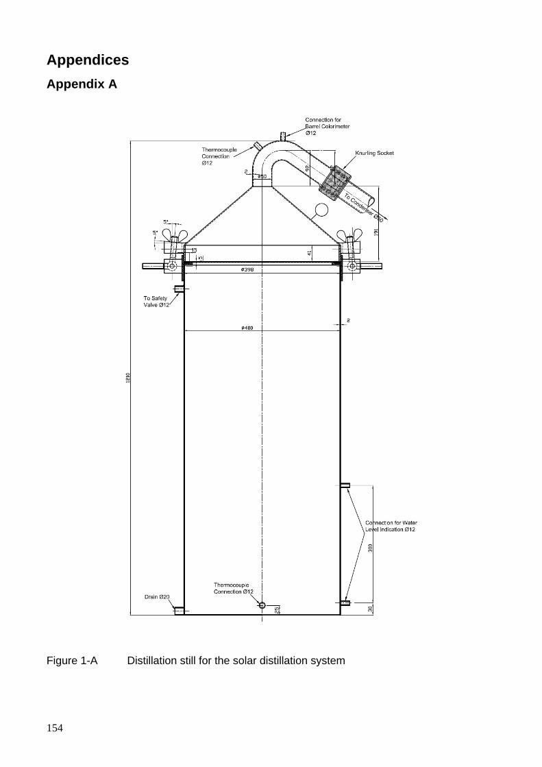
154
Appendices Appendix A
Figure 1-A Distillation still for the solar distillation system
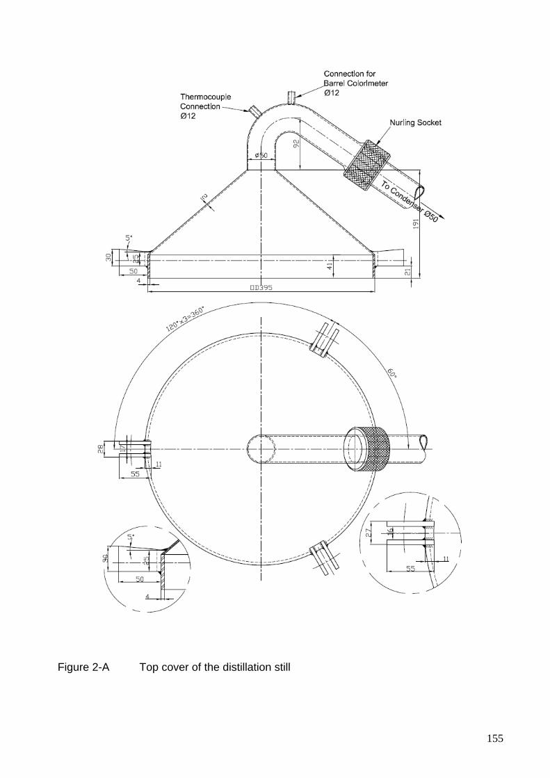
155
Figure 2-A Top cover of the distillation still
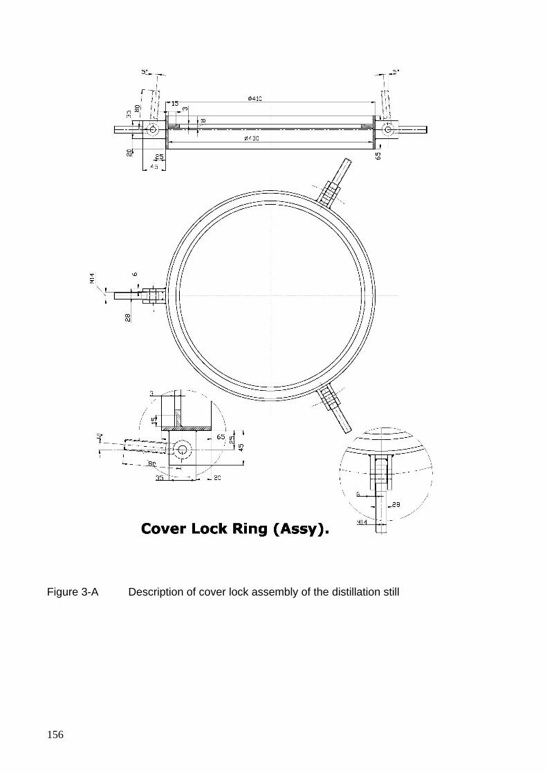
156
Figure 3-A Description of cover lock assembly of the distillation still
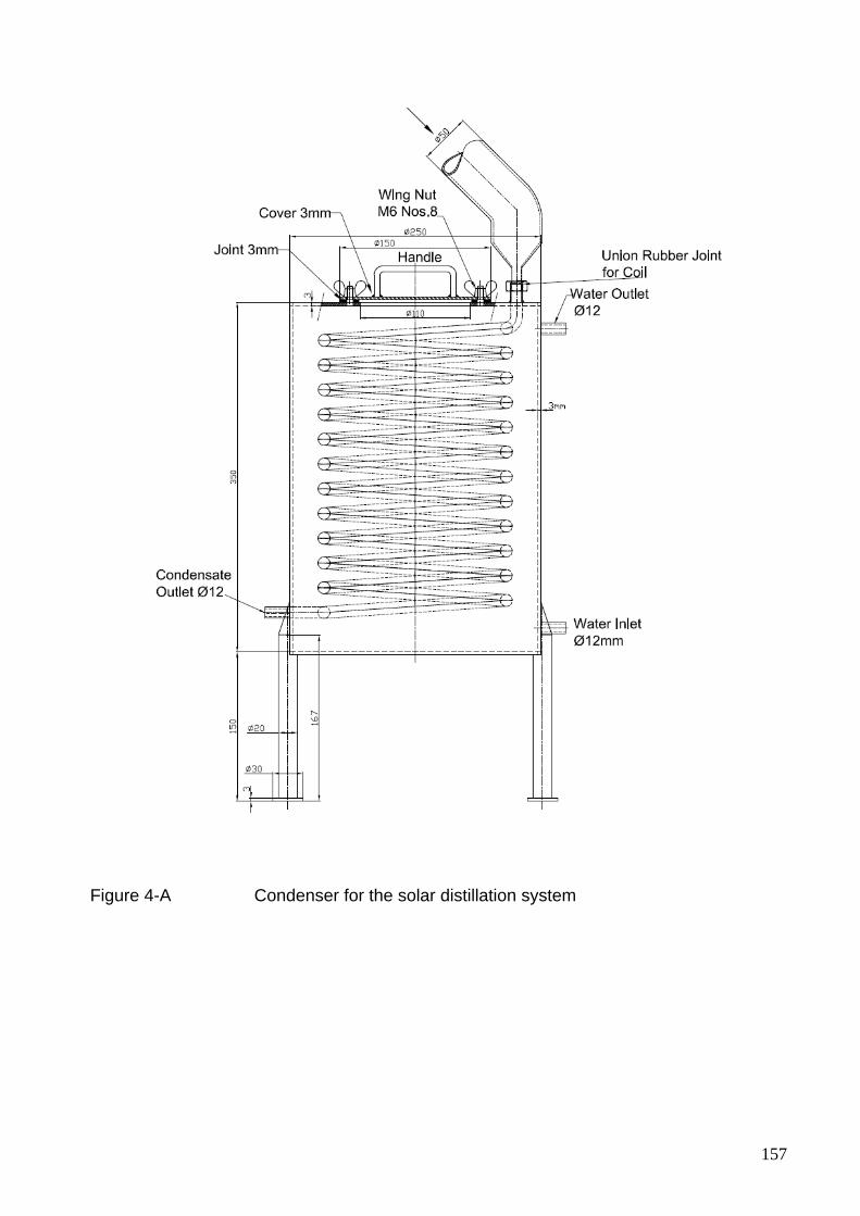
157
Figure 4-A Condenser for the solar distillation system

158
Appendix B
Date Day of the
year “n”
Delta “б”
(degrees)
Aperture in
Northern
hemisphere
“As” (m2)
Aperture in
Southern
hemisphere
“As” (m2)
1-Jan 1 -23.06 6.80 4.61
2-Jan 2 -22.98 6.80 4.62
3-Jan 3 -22.89 6.79 4.62
4-Jan 4 -22.80 6.79 4.63
5-Jan 5 -22.70 6.79 4.63
6-Jan 6 -22.59 6.78 4.64
7-Jan 7 -22.47 6.78 4.64
8-Jan 8 -22.35 6.77 4.65
9-Jan 9 -22.21 6.77 4.66
10-Jan 10 -22.07 6.76 4.67
11-Jan 11 -21.93 6.76 4.68
12-Jan 12 -21.77 6.75 4.68
13-Jan 13 -21.61 6.75 4.69
14-Jan 14 -21.45 6.74 4.70
15-Jan 15 -21.27 6.73 4.71
16-Jan 16 -21.09 6.73 4.72
17-Jan 17 -20.90 6.72 4.73
18-Jan 18 -20.71 6.71 4.74
19-Jan 19 -20.51 6.70 4.76
20-Jan 20 -20.30 6.70 4.77
21-Jan 21 -20.09 6.69 4.78
22-Jan 22 -19.87 6.68 4.79
23-Jan 23 -19.64 6.67 4.80
24-Jan 24 -19.41 6.66 4.82
25-Jan 25 -19.17 6.65 4.83
26-Jan 26 -18.92 6.64 4.84
27-Jan 27 -18.67 6.63 4.86
28-Jan 28 -18.42 6.62 4.87
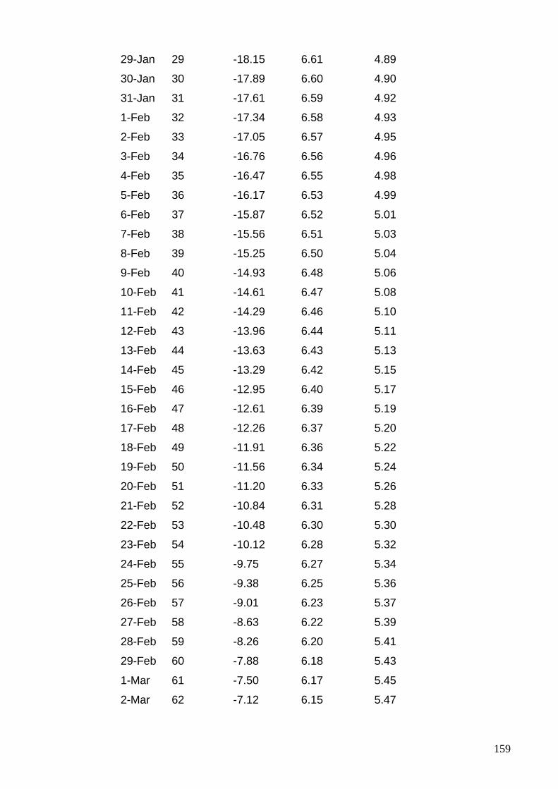
159
29-Jan 29 -18.15 6.61 4.89
30-Jan 30 -17.89 6.60 4.90
31-Jan 31 -17.61 6.59 4.92
1-Feb 32 -17.34 6.58 4.93
2-Feb 33 -17.05 6.57 4.95
3-Feb 34 -16.76 6.56 4.96
4-Feb 35 -16.47 6.55 4.98
5-Feb 36 -16.17 6.53 4.99
6-Feb 37 -15.87 6.52 5.01
7-Feb 38 -15.56 6.51 5.03
8-Feb 39 -15.25 6.50 5.04
9-Feb 40 -14.93 6.48 5.06
10-Feb 41 -14.61 6.47 5.08
11-Feb 42 -14.29 6.46 5.10
12-Feb 43 -13.96 6.44 5.11
13-Feb 44 -13.63 6.43 5.13
14-Feb 45 -13.29 6.42 5.15
15-Feb 46 -12.95 6.40 5.17
16-Feb 47 -12.61 6.39 5.19
17-Feb 48 -12.26 6.37 5.20
18-Feb 49 -11.91 6.36 5.22
19-Feb 50 -11.56 6.34 5.24
20-Feb 51 -11.20 6.33 5.26
21-Feb 52 -10.84 6.31 5.28
22-Feb 53 -10.48 6.30 5.30
23-Feb 54 -10.12 6.28 5.32
24-Feb 55 -9.75 6.27 5.34
25-Feb 56 -9.38 6.25 5.36
26-Feb 57 -9.01 6.23 5.37
27-Feb 58 -8.63 6.22 5.39
28-Feb 59 -8.26 6.20 5.41
29-Feb 60 -7.88 6.18 5.43
1-Mar 61 -7.50 6.17 5.45
2-Mar 62 -7.12 6.15 5.47
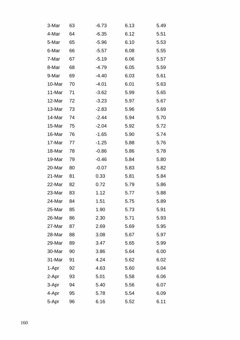
160
3-Mar 63 -6.73 6.13 5.49
4-Mar 64 -6.35 6.12 5.51
5-Mar 65 -5.96 6.10 5.53
6-Mar 66 -5.57 6.08 5.55
7-Mar 67 -5.19 6.06 5.57
8-Mar 68 -4.79 6.05 5.59
9-Mar 69 -4.40 6.03 5.61
10-Mar 70 -4.01 6.01 5.63
11-Mar 71 -3.62 5.99 5.65
12-Mar 72 -3.23 5.97 5.67
13-Mar 73 -2.83 5.96 5.69
14-Mar 74 -2.44 5.94 5.70
15-Mar 75 -2.04 5.92 5.72
16-Mar 76 -1.65 5.90 5.74
17-Mar 77 -1.25 5.88 5.76
18-Mar 78 -0.86 5.86 5.78
19-Mar 79 -0.46 5.84 5.80
20-Mar 80 -0.07 5.83 5.82
21-Mar 81 0.33 5.81 5.84
22-Mar 82 0.72 5.79 5.86
23-Mar 83 1.12 5.77 5.88
24-Mar 84 1.51 5.75 5.89
25-Mar 85 1.90 5.73 5.91
26-Mar 86 2.30 5.71 5.93
27-Mar 87 2.69 5.69 5.95
28-Mar 88 3.08 5.67 5.97
29-Mar 89 3.47 5.65 5.99
30-Mar 90 3.86 5.64 6.00
31-Mar 91 4.24 5.62 6.02
1-Apr 92 4.63 5.60 6.04
2-Apr 93 5.01 5.58 6.06
3-Apr 94 5.40 5.56 6.07
4-Apr 95 5.78 5.54 6.09
5-Apr 96 6.16 5.52 6.11
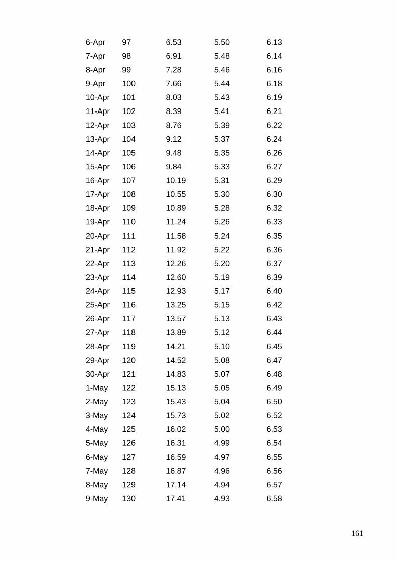
161
6-Apr 97 6.53 5.50 6.13
7-Apr 98 6.91 5.48 6.14
8-Apr 99 7.28 5.46 6.16
9-Apr 100 7.66 5.44 6.18
10-Apr 101 8.03 5.43 6.19
11-Apr 102 8.39 5.41 6.21
12-Apr 103 8.76 5.39 6.22
13-Apr 104 9.12 5.37 6.24
14-Apr 105 9.48 5.35 6.26
15-Apr 106 9.84 5.33 6.27
16-Apr 107 10.19 5.31 6.29
17-Apr 108 10.55 5.30 6.30
18-Apr 109 10.89 5.28 6.32
19-Apr 110 11.24 5.26 6.33
20-Apr 111 11.58 5.24 6.35
21-Apr 112 11.92 5.22 6.36
22-Apr 113 12.26 5.20 6.37
23-Apr 114 12.60 5.19 6.39
24-Apr 115 12.93 5.17 6.40
25-Apr 116 13.25 5.15 6.42
26-Apr 117 13.57 5.13 6.43
27-Apr 118 13.89 5.12 6.44
28-Apr 119 14.21 5.10 6.45
29-Apr 120 14.52 5.08 6.47
30-Apr 121 14.83 5.07 6.48
1-May 122 15.13 5.05 6.49
2-May 123 15.43 5.04 6.50
3-May 124 15.73 5.02 6.52
4-May 125 16.02 5.00 6.53
5-May 126 16.31 4.99 6.54
6-May 127 16.59 4.97 6.55
7-May 128 16.87 4.96 6.56
8-May 129 17.14 4.94 6.57
9-May 130 17.41 4.93 6.58
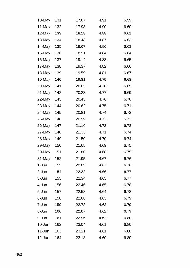
162
10-May 131 17.67 4.91 6.59
11-May 132 17.93 4.90 6.60
12-May 133 18.18 4.88 6.61
13-May 134 18.43 4.87 6.62
14-May 135 18.67 4.86 6.63
15-May 136 18.91 4.84 6.64
16-May 137 19.14 4.83 6.65
17-May 138 19.37 4.82 6.66
18-May 139 19.59 4.81 6.67
19-May 140 19.81 4.79 6.68
20-May 141 20.02 4.78 6.69
21-May 142 20.23 4.77 6.69
22-May 143 20.43 4.76 6.70
23-May 144 20.62 4.75 6.71
24-May 145 20.81 4.74 6.72
25-May 146 20.99 4.73 6.72
26-May 147 21.16 4.72 6.73
27-May 148 21.33 4.71 6.74
28-May 149 21.50 4.70 6.74
29-May 150 21.65 4.69 6.75
30-May 151 21.80 4.68 6.75
31-May 152 21.95 4.67 6.76
1-Jun 153 22.09 4.67 6.76
2-Jun 154 22.22 4.66 6.77
3-Jun 155 22.34 4.65 6.77
4-Jun 156 22.46 4.65 6.78
5-Jun 157 22.58 4.64 6.78
6-Jun 158 22.68 4.63 6.79
7-Jun 159 22.78 4.63 6.79
8-Jun 160 22.87 4.62 6.79
9-Jun 161 22.96 4.62 6.80
10-Jun 162 23.04 4.61 6.80
11-Jun 163 23.11 4.61 6.80
12-Jun 164 23.18 4.60 6.80
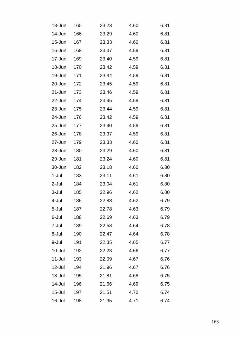
163
13-Jun 165 23.23 4.60 6.81
14-Jun 166 23.29 4.60 6.81
15-Jun 167 23.33 4.60 6.81
16-Jun 168 23.37 4.59 6.81
17-Jun 169 23.40 4.59 6.81
18-Jun 170 23.42 4.59 6.81
19-Jun 171 23.44 4.59 6.81
20-Jun 172 23.45 4.59 6.81
21-Jun 173 23.46 4.59 6.81
22-Jun 174 23.45 4.59 6.81
23-Jun 175 23.44 4.59 6.81
24-Jun 176 23.42 4.59 6.81
25-Jun 177 23.40 4.59 6.81
26-Jun 178 23.37 4.59 6.81
27-Jun 179 23.33 4.60 6.81
28-Jun 180 23.29 4.60 6.81
29-Jun 181 23.24 4.60 6.81
30-Jun 182 23.18 4.60 6.80
1-Jul 183 23.11 4.61 6.80
2-Jul 184 23.04 4.61 6.80
3-Jul 185 22.96 4.62 6.80
4-Jul 186 22.88 4.62 6.79
5-Jul 187 22.78 4.63 6.79
6-Jul 188 22.69 4.63 6.79
7-Jul 189 22.58 4.64 6.78
8-Jul 190 22.47 4.64 6.78
9-Jul 191 22.35 4.65 6.77
10-Jul 192 22.23 4.66 6.77
11-Jul 193 22.09 4.67 6.76
12-Jul 194 21.96 4.67 6.76
13-Jul 195 21.81 4.68 6.75
14-Jul 196 21.66 4.69 6.75
15-Jul 197 21.51 4.70 6.74
16-Jul 198 21.35 4.71 6.74
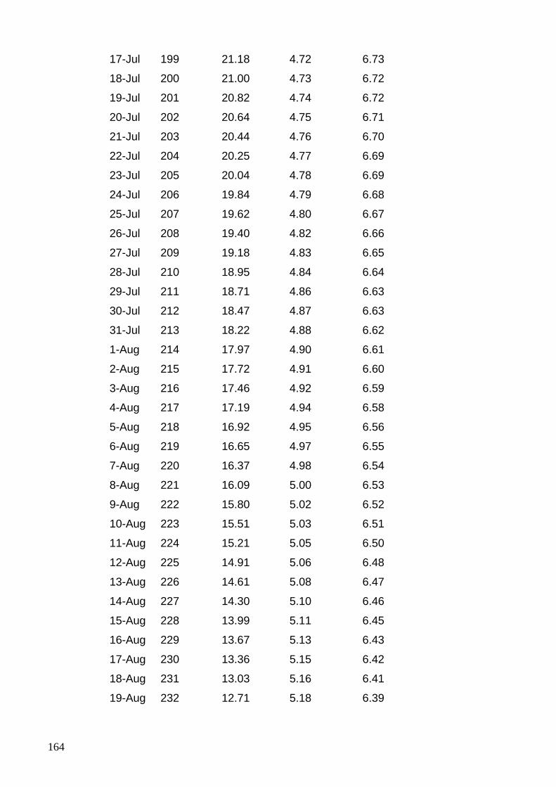
164
17-Jul 199 21.18 4.72 6.73
18-Jul 200 21.00 4.73 6.72
19-Jul 201 20.82 4.74 6.72
20-Jul 202 20.64 4.75 6.71
21-Jul 203 20.44 4.76 6.70
22-Jul 204 20.25 4.77 6.69
23-Jul 205 20.04 4.78 6.69
24-Jul 206 19.84 4.79 6.68
25-Jul 207 19.62 4.80 6.67
26-Jul 208 19.40 4.82 6.66
27-Jul 209 19.18 4.83 6.65
28-Jul 210 18.95 4.84 6.64
29-Jul 211 18.71 4.86 6.63
30-Jul 212 18.47 4.87 6.63
31-Jul 213 18.22 4.88 6.62
1-Aug 214 17.97 4.90 6.61
2-Aug 215 17.72 4.91 6.60
3-Aug 216 17.46 4.92 6.59
4-Aug 217 17.19 4.94 6.58
5-Aug 218 16.92 4.95 6.56
6-Aug 219 16.65 4.97 6.55
7-Aug 220 16.37 4.98 6.54
8-Aug 221 16.09 5.00 6.53
9-Aug 222 15.80 5.02 6.52
10-Aug 223 15.51 5.03 6.51
11-Aug 224 15.21 5.05 6.50
12-Aug 225 14.91 5.06 6.48
13-Aug 226 14.61 5.08 6.47
14-Aug 227 14.30 5.10 6.46
15-Aug 228 13.99 5.11 6.45
16-Aug 229 13.67 5.13 6.43
17-Aug 230 13.36 5.15 6.42
18-Aug 231 13.03 5.16 6.41
19-Aug 232 12.71 5.18 6.39
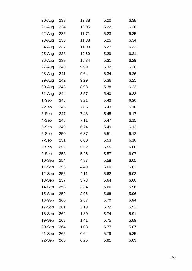
165
20-Aug 233 12.38 5.20 6.38
21-Aug 234 12.05 5.22 6.36
22-Aug 235 11.71 5.23 6.35
23-Aug 236 11.38 5.25 6.34
24-Aug 237 11.03 5.27 6.32
25-Aug 238 10.69 5.29 6.31
26-Aug 239 10.34 5.31 6.29
27-Aug 240 9.99 5.32 6.28
28-Aug 241 9.64 5.34 6.26
29-Aug 242 9.29 5.36 6.25
30-Aug 243 8.93 5.38 6.23
31-Aug 244 8.57 5.40 6.22
1-Sep 245 8.21 5.42 6.20
2-Sep 246 7.85 5.43 6.18
3-Sep 247 7.48 5.45 6.17
4-Sep 248 7.11 5.47 6.15
5-Sep 249 6.74 5.49 6.13
6-Sep 250 6.37 5.51 6.12
7-Sep 251 6.00 5.53 6.10
8-Sep 252 5.62 5.55 6.08
9-Sep 253 5.25 5.57 6.07
10-Sep 254 4.87 5.58 6.05
11-Sep 255 4.49 5.60 6.03
12-Sep 256 4.11 5.62 6.02
13-Sep 257 3.73 5.64 6.00
14-Sep 258 3.34 5.66 5.98
15-Sep 259 2.96 5.68 5.96
16-Sep 260 2.57 5.70 5.94
17-Sep 261 2.19 5.72 5.93
18-Sep 262 1.80 5.74 5.91
19-Sep 263 1.41 5.75 5.89
20-Sep 264 1.03 5.77 5.87
21-Sep 265 0.64 5.79 5.85
22-Sep 266 0.25 5.81 5.83
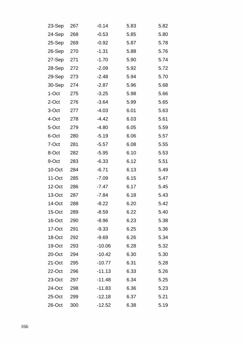
166
23-Sep 267 -0.14 5.83 5.82
24-Sep 268 -0.53 5.85 5.80
25-Sep 269 -0.92 5.87 5.78
26-Sep 270 -1.31 5.88 5.76
27-Sep 271 -1.70 5.90 5.74
28-Sep 272 -2.09 5.92 5.72
29-Sep 273 -2.48 5.94 5.70
30-Sep 274 -2.87 5.96 5.68
1-Oct 275 -3.25 5.98 5.66
2-Oct 276 -3.64 5.99 5.65
3-Oct 277 -4.03 6.01 5.63
4-Oct 278 -4.42 6.03 5.61
5-Oct 279 -4.80 6.05 5.59
6-Oct 280 -5.19 6.06 5.57
7-Oct 281 -5.57 6.08 5.55
8-Oct 282 -5.95 6.10 5.53
9-Oct 283 -6.33 6.12 5.51
10-Oct 284 -6.71 6.13 5.49
11-Oct 285 -7.09 6.15 5.47
12-Oct 286 -7.47 6.17 5.45
13-Oct 287 -7.84 6.18 5.43
14-Oct 288 -8.22 6.20 5.42
15-Oct 289 -8.59 6.22 5.40
16-Oct 290 -8.96 6.23 5.38
17-Oct 291 -9.33 6.25 5.36
18-Oct 292 -9.69 6.26 5.34
19-Oct 293 -10.06 6.28 5.32
20-Oct 294 -10.42 6.30 5.30
21-Oct 295 -10.77 6.31 5.28
22-Oct 296 -11.13 6.33 5.26
23-Oct 297 -11.48 6.34 5.25
24-Oct 298 -11.83 6.36 5.23
25-Oct 299 -12.18 6.37 5.21
26-Oct 300 -12.52 6.38 5.19

167
27-Oct 301 -12.86 6.40 5.17
28-Oct 302 -13.20 6.41 5.16
29-Oct 303 -13.53 6.43 5.14
30-Oct 304 -13.86 6.44 5.12
31-Oct 305 -14.19 6.45 5.10
1-Nov 306 -14.51 6.47 5.08
2-Nov 307 -14.83 6.48 5.07
3-Nov 308 -15.14 6.49 5.05
4-Nov 309 -15.46 6.51 5.03
5-Nov 310 -15.76 6.52 5.02
6-Nov 311 -16.06 6.53 5.00
7-Nov 312 -16.36 6.54 4.98
8-Nov 313 -16.65 6.55 4.97
9-Nov 314 -16.94 6.57 4.95
10-Nov 315 -17.22 6.58 4.94
11-Nov 316 -17.50 6.59 4.92
12-Nov 317 -17.77 6.60 4.91
13-Nov 318 -18.04 6.61 4.89
14-Nov 319 -18.30 6.62 4.88
15-Nov 320 -18.56 6.63 4.86
16-Nov 321 -18.81 6.64 4.85
17-Nov 322 -19.06 6.65 4.84
18-Nov 323 -19.30 6.66 4.82
19-Nov 324 -19.53 6.67 4.81
20-Nov 325 -19.76 6.68 4.80
21-Nov 326 -19.98 6.68 4.78
22-Nov 327 -20.20 6.69 4.77
23-Nov 328 -20.41 6.70 4.76
24-Nov 329 -20.61 6.71 4.75
25-Nov 330 -20.81 6.72 4.74
26-Nov 331 -21.00 6.72 4.73
27-Nov 332 -21.18 6.73 4.72
28-Nov 333 -21.36 6.74 4.71
29-Nov 334 -21.53 6.74 4.70
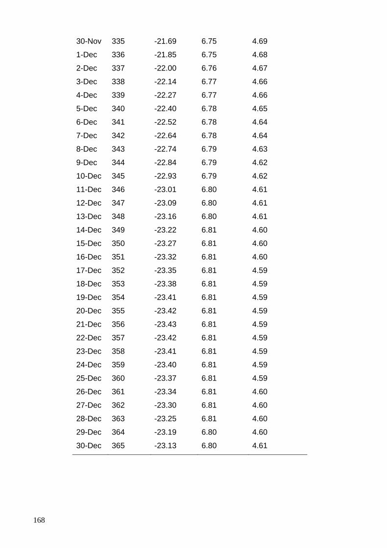
168
30-Nov 335 -21.69 6.75 4.69
1-Dec 336 -21.85 6.75 4.68
2-Dec 337 -22.00 6.76 4.67
3-Dec 338 -22.14 6.77 4.66
4-Dec 339 -22.27 6.77 4.66
5-Dec 340 -22.40 6.78 4.65
6-Dec 341 -22.52 6.78 4.64
7-Dec 342 -22.64 6.78 4.64
8-Dec 343 -22.74 6.79 4.63
9-Dec 344 -22.84 6.79 4.62
10-Dec 345 -22.93 6.79 4.62
11-Dec 346 -23.01 6.80 4.61
12-Dec 347 -23.09 6.80 4.61
13-Dec 348 -23.16 6.80 4.61
14-Dec 349 -23.22 6.81 4.60
15-Dec 350 -23.27 6.81 4.60
16-Dec 351 -23.32 6.81 4.60
17-Dec 352 -23.35 6.81 4.59
18-Dec 353 -23.38 6.81 4.59
19-Dec 354 -23.41 6.81 4.59
20-Dec 355 -23.42 6.81 4.59
21-Dec 356 -23.43 6.81 4.59
22-Dec 357 -23.42 6.81 4.59
23-Dec 358 -23.41 6.81 4.59
24-Dec 359 -23.40 6.81 4.59
25-Dec 360 -23.37 6.81 4.59
26-Dec 361 -23.34 6.81 4.60
27-Dec 362 -23.30 6.81 4.60
28-Dec 363 -23.25 6.81 4.60
29-Dec 364 -23.19 6.80 4.60
30-Dec 365 -23.13 6.80 4.61
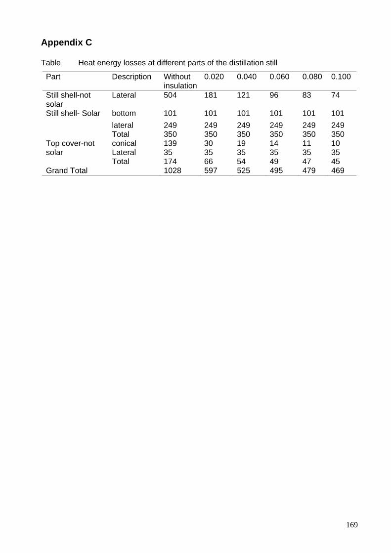
169
Appendix C Table Heat energy losses at different parts of the distillation still
Part Description Without insulation
0.020 0.040 0.060 0.080 0.100
Still shell-not solar
Lateral 504 181 121 96 83 74
Still shell- Solar bottom 101 101 101 101 101 101 lateral 249 249 249 249 249 249 Total 350 350 350 350 350 350
Top cover-not solar
conical 139 30 19 14 11 10 Lateral 35 35 35 35 35 35 Total 174 66 54 49 47 45
Grand Total 1028 597 525 495 479 469
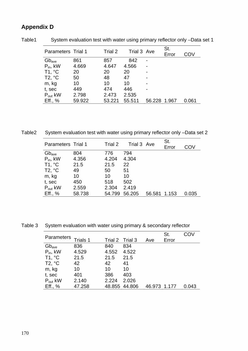
170
Appendix D Table1 System evaluation test with water using primary reflector only –Data set 1
Parameters Trial 1 Trial 2 Trial 3 Ave St. Error COV
Gbave 861 857 842 - Pin, kW 4.669 4.647 4.566 - T1, °C 20 20 20 - T2, °C 50 48 47 - m, kg 10 10 10 - t, sec 449 474 446 - Pout kW 2.798 2.473 2.535 Eff., % 59.922 53.221 55.511 56.228 1.967 0.061
Table2 System evaluation test with water using primary reflector only –Data set 2
Parameters Trial 1 Trial 2 Trial 3 Ave St. Error COV
Gbave 804 776 794 Pin, kW 4.356 4.204 4.304 T1, °C 21.5 21.5 22 T2, °C 49 50 51 m, kg 10 10 10 t, sec 450 518 502 Pout kW 2.559 2.304 2.419 Eff., % 58.738 54.799 56.205 56.581 1.153 0.035
Table 3 System evaluation with water using primary & secondary reflector
Parameters Trials 1 Trial 2 Trial 3 Ave St. Error
COV
Gbave 836 840 834 Pin, kW 4.529 4.552 4.522 T1, °C 21.5 21.5 21.5 T2, °C 42 42 41 m, kg 10 10 10 t, sec 401 386 403 Pout kW 2.140 2.224 2.026 Eff., % 47.258 48.855 44.806 46.973 1.177 0.043
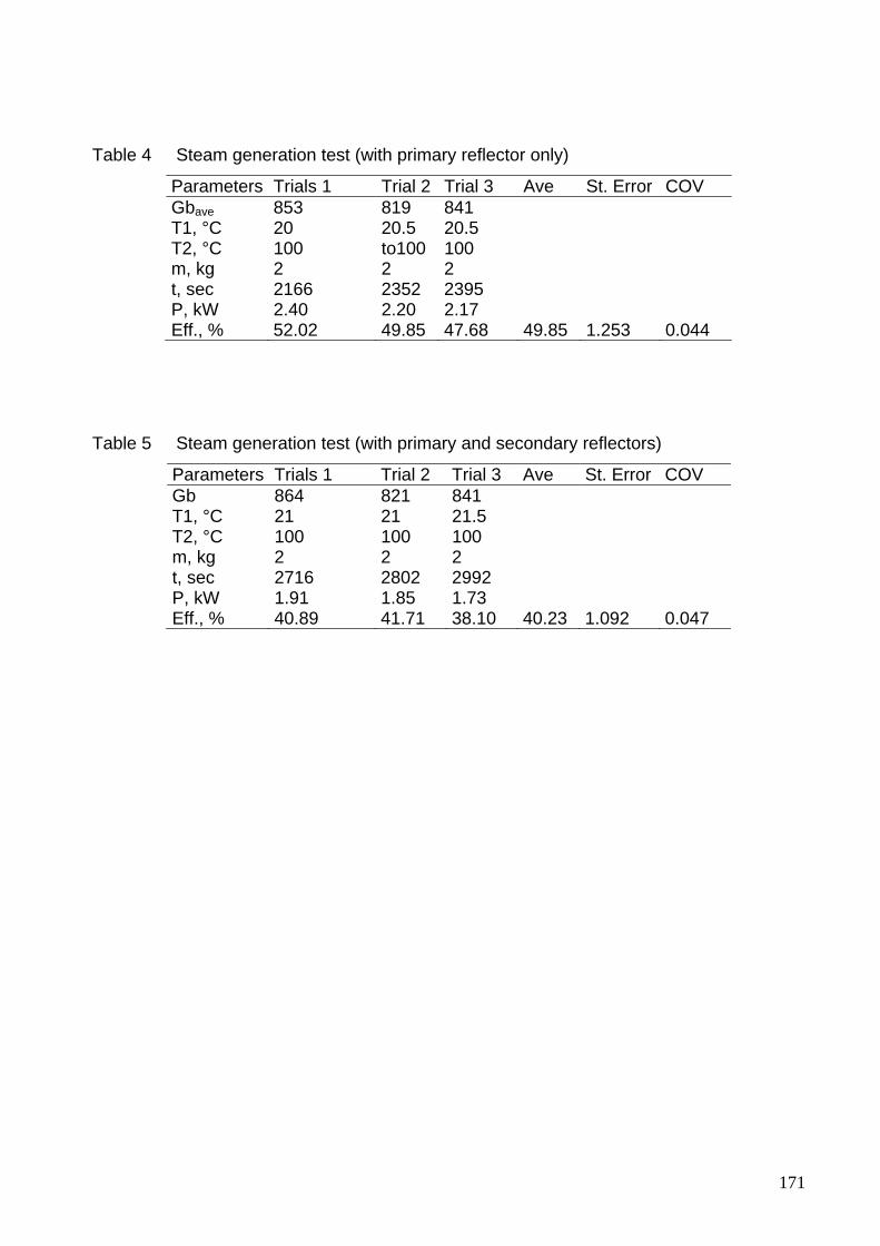
171
Table 4 Steam generation test (with primary reflector only)
Parameters Trials 1 Trial 2 Trial 3 Ave St. Error COV Gbave 853 819 841 T1, °C 20 20.5 20.5 T2, °C 100 to100 100 m, kg 2 2 2 t, sec 2166 2352 2395 P, kW 2.40 2.20 2.17 Eff., % 52.02 49.85 47.68 49.85 1.253 0.044
Table 5 Steam generation test (with primary and secondary reflectors)
Parameters Trials 1 Trial 2 Trial 3 Ave St. Error COV Gb 864 821 841 T1, °C 21 21 21.5 T2, °C 100 100 100 m, kg 2 2 2 t, sec 2716 2802 2992 P, kW 1.91 1.85 1.73 Eff., % 40.89 41.71 38.10 40.23 1.092 0.047

172
Appendix E
Figure Solar tunnel dryer (Hohenheim design)
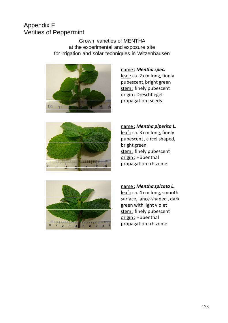
173
Appendix F Verities of Peppermint
name :Mentha spec.leaf : ca. 2 cm long, finely pubescent, bright greenstem : finely pubescent origin : Dreschflegelpropagation : seeds
name :Mentha piperita L.leaf : ca. 3 cm long, finely pubescent , circel shaped, bright greenstem : finely pubescent origin : Hübenthalpropagation : rhizome
name :Mentha spicata L. leaf : ca. 4 cm long, smooth surface, lance‐shaped , dark green with light violetstem : finely pubescent origin : Hübenthalpropagation : rhizome
Grown varieties of MENTHA at the experimental and exposure site
for irrigation and solar techniques in Witzenhausen

ISSN 0931-6264