design and virtual prototyping of human-worn manipulation devices peng song grasp laboratory...
TRANSCRIPT

Design and Virtual Prototyping of Human-worn Manipulation Devices
Peng SongGRASP Laboratory
University of Pennsylvania
ASME DETC99/CIE-9029
GRASPLaboratory
Venkat KroviMechanical Engineering Dept.
McGill University
Richard MahoneyRehabilitation Technologies Division
Applied Resources Corporation
Vijay KumarGRASP Laboratory
University of Pennsylvania
MOTIVATION
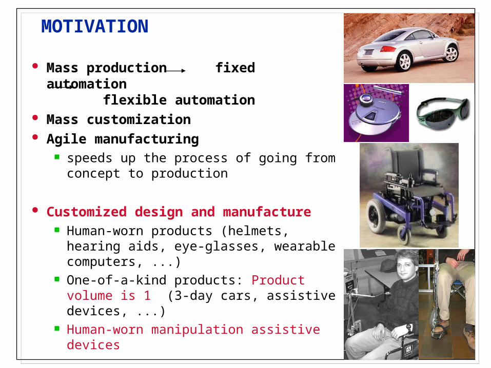
Mass production fixed automation flexible automation
Mass customization Agile manufacturing
speeds up the process of going from concept to production
Customized design and manufacture Human-worn products (helmets, hearing
aids, eye-glasses, wearable computers, ...) One-of-a-kind products: Product volume is 1
(3-day cars, assistive devices, ...) Human-worn manipulation assistive devices
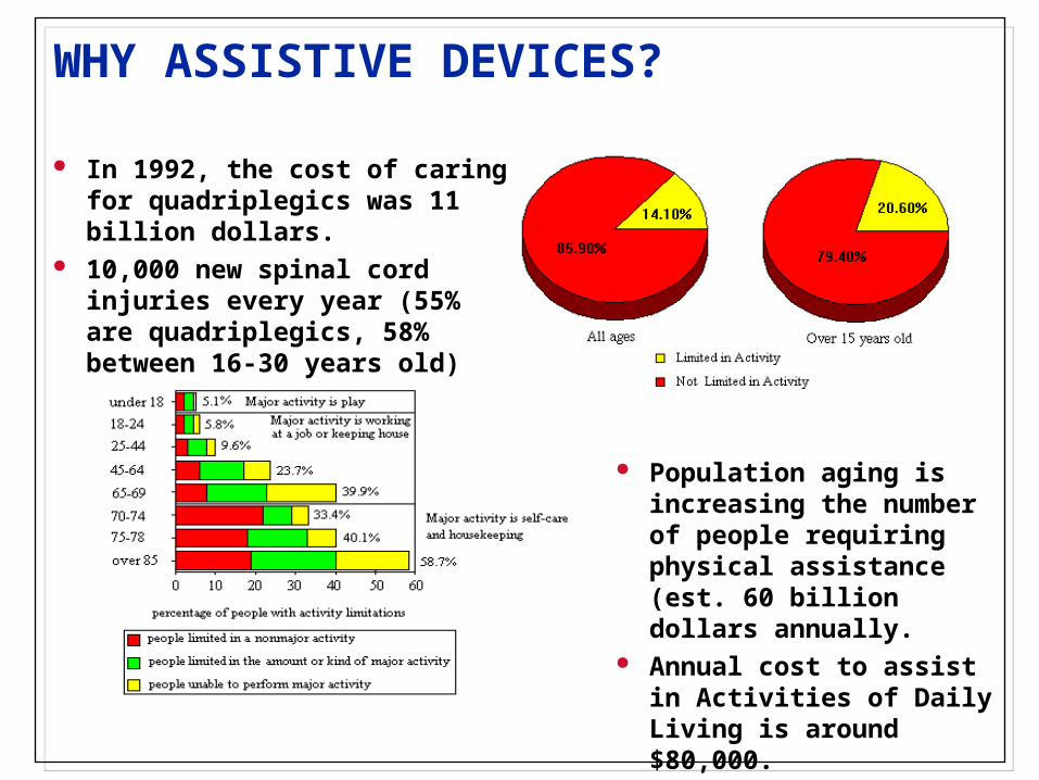
In 1992, the cost of caring for quadriplegics was 11 billion dollars.
10,000 new spinal cord injuries every year (55% are quadriplegics, 58% between 16-30 years old)
Population aging is increasing the number of people requiring physical assistance (est. 60 billion dollars annually.
Annual cost to assist in Activities of Daily Living is around $80,000.
WHY ASSISTIVE DEVICES?

WHY CUSTOMIZATION?
Variability exists in user needs across the population. Products must be designed and customized to match these individual user needs.
The device-user customization ensures comfort of user and enhances performance of the device.

HUMAN-WORN MANIPULATION DEVICES

HUMAN-WORN MANIPULATION DEVICES
GOALS
Identify and investigate the component technologies required for designing, customizing, virtually prototyping and finally fabricating human-worn manipulation assistive devices for the motor disabled.
Present a unified design environment which integrates these component technologies and aids the designer in shortening the design cycle.
The design-customization-integration process can be extended to many classes of human worn products.

KEYS TO CUSTOMIZATION
1. DATA ACQUISITIONMeasurement of the human user, the task, and the environment.
2. DEVICE DESIGN AND OPTIMIZATION
Mechanism synthesis (generating the desired “output” motion/force from the specified human “input” motion/force), CAD modeling.
3. VIRTUAL PROTOTYPING AND EVALUATION
Geometric and dynamic modeling of the human user, the designed product, and simulation of the human using the product prior to rapid fabrication.

1. DATA ACQUISITION
GEOMETRY CAPTURE
in 3-D studio
CUSTOMIZED MODEL
MOTION CAPTURE
in 3-D Studio

1. DATA ACQUISITION: Measurement to models
Solid models generated from image data using Multi-camera, multi-pose measurements Cyberware 3D scanner
Meshed Solid models for CAD (Pro/Engineer) CAM (CNC machining) FEM/FEA
Kinematic and dynamic models for Virtual prototyping Analysis and simulation
Provides important tools for Re-design Customization One-of-a-kind prototyping Reverse engineering

DESIGNER
AUTOMATION
2. DEVICE DESIGN AND OPTIMIZATION
COUPLINGCOUPLINGINPUT DEVICEINPUT DEVICE
ChoicesChoices
OUTPUT DEVICEOUTPUT DEVICE
ChoicesChoices
Geometric MechanismDegrees of Freedom
Mechanism GeometricDegrees of Freedom
HUMAN INPUTMOTION, u
DESIREDOUTPUTMOTION
y(1, 2,..., n)
DATA ACQUISITION,MODELING
u(1, 2,..., n) MODELREDUCTION
u()
INPUTSUBSYSTEM
TRANSFORMATION()
EFFECTORSUBSYSTEM
1(), 2( ),..., n( )
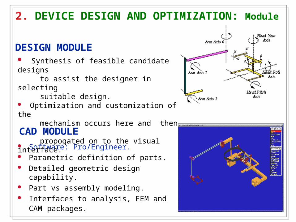
Software: Pro/Engineer. Parametric definition of parts. Detailed geometric design capability. Part vs assembly modeling. Interfaces to analysis, FEM and CAM
packages.
2. DEVICE DESIGN AND OPTIMIZATION: Module
Synthesis of feasible candidate designs to assist the designer in selecting suitable design. Optimization and customization of the mechanism occurs here and then propogated on to the visual interface.
CAD MODULE
DESIGN MODULE

Obtain kinematic model of movement and determine appropriate input motion.
Choose appropriate output motions.
Preliminary design: select candidate mechanism.
Use virtual models to investigate the mechanism.
Customize the mechanism to the individual user and build a virtual prototype.
After testing and evaluation, build the physical prototype.
2. DEVICE DESIGN AND OPTIMIZATION: Process
a0
a1
a2
0
1
2
3
x
y
x
y HEAD BAND
r1
r2
r0

Virtual prototype ofeffector subsystem
Synthetic human model
Virtual prototype ofcoupling subsystem
Virtual prototype ofinput subsystem
Customer
Customer
VIRTUAL
WORLD
PHYSICAL
WORLD
DESIGN AND VIRTUALPROTOTYPING
INTERMEDIATEPROTOTYPE
FINAL PROTOTYPE
Designer
Physical prototype ofinput subsystem
Electronic interface
Communication
Virtual prototype ofeffector subsystem
Virtual prototype ofcoupling subsystem
Physical prototype ofinput subsystem
Physical prototype ofeffector subsystem
Physical prototype ofcoupling subsystem
3. VIRTUAL PROTOTYPING AND EVALUATION
Parametric mapping
Kinematic and dynamic evaluation with a model of the user
Design optimization and customization
Virtual and physical prototypes of the input subsystem and effector subsystem

DESIGN ENVIRONMENT
CENTRAL INTERFACE
GEOMETRIC MODELING
Cyberwarerange
scanner
Videocameras
Manipulandum
KINEMATIC MODELING
DYNAMIC ANALYSIS
CAD/CAM ProEngineer
VISUALIZATION (JACK, GeomView,
ProEnginer)
DESIGN OPTIMIZATION
Surface mesh
Motion
3-D model
simulation
MANUFACTURING
Customized components
Off-the-shelf components

Unified framework for analyzing data (geometry, kinematics, dynamics), testing (simulating) and evaluating products.
Graphical, user-friendly interface.
Heterogeneous data.
Modular.
Uses standard packages/formats.
DESIGN ENVIRONMENT: Central Interface
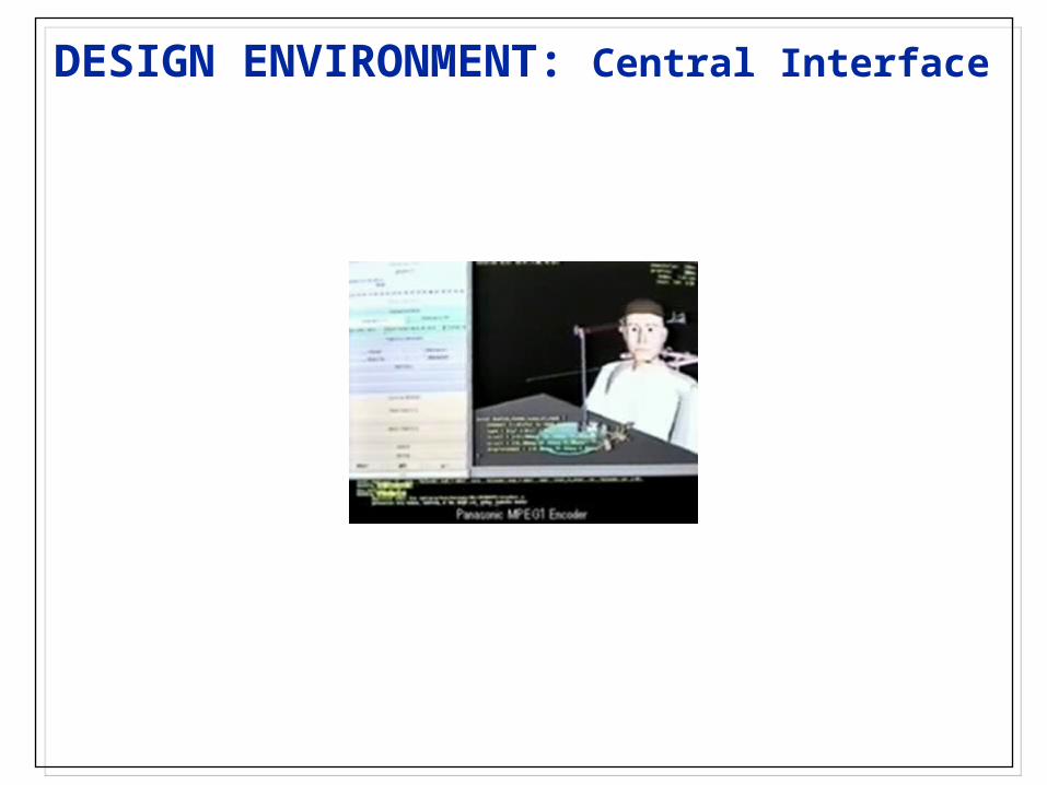
DESIGN ENVIRONMENT: Central Interface

CASE 1: Head-controlled Feeding Device
DESIGN SELECTION
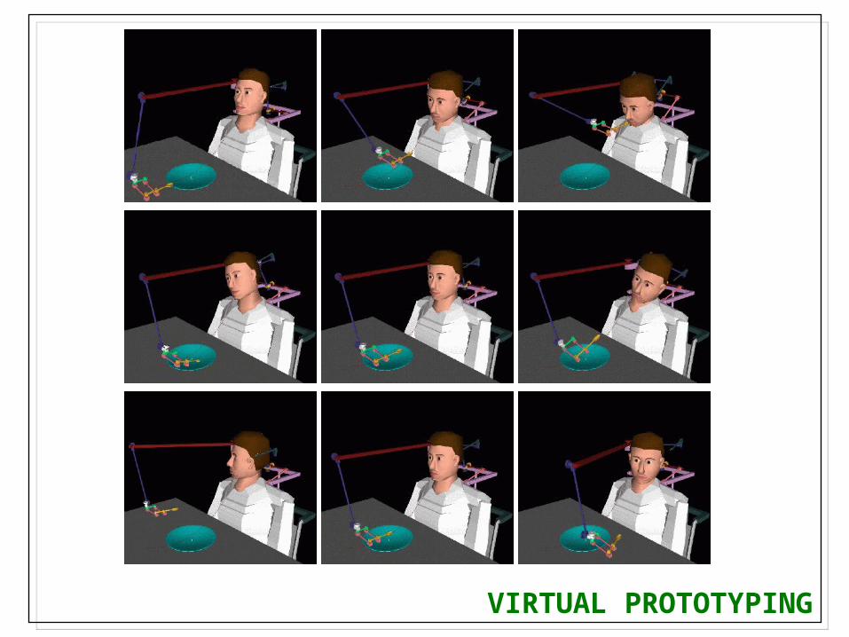
VIRTUAL PROTOTYPING

VIRTUAL PROTOTYPING

FABRICATED PROTOTYPE

CASE 2: Head-controlled Painting Tool
DESIGN SELECTION

VIRTUAL PROTOTYPING

VIRTUAL PROTOTYPING

FABRICATED PROTOTYPE

FABRICATED PROTOTYPE

SUMMARY
Key Ideas Integrated design environment aids the designer in the rapid
realization of “one-of-a-kind” products customized to individual users
Only feasible designs are created by design module effectively reducing the optimization search space.
Virtual prototyping enables rapid evaluation within these feasible design choices.
Customized design methodology applicable to many classes of human-worn devices which need to be customized to individuals.
Limitation The component technologies are often specific to the product