design and simulation of a high order mode cavity bunch
TRANSCRIPT

Submitted to Chinese Physics C
Design and Simulation of a high order mode cavity bunch length monitor
Jiang Guo (郭江) ZeRan Zhou (周泽然) Qing Luo (罗箐)
National Synchrotron Radiation Laboratory, University of Science and Technology of China, Hefei 230029, China
Abstract: A new bunch length measurement method based on high order mode cavity was
proposed. Operating the harmonic cavity at mode TM0n0 so that its radius could be chosen, in
order to break the limitation of beam pipe radius. A two-cavity bunch length monitor for linac of
positron source was designed. Operating frequency selection for different bunch time structure
was discussed and calculation formula of bunch length was deducted. Fundamental harmonic
cavity resonates at 2.856 GHz with mode TM010. Fifth harmonic cavity resonates at 14.28 GHz
(fifth harmonic of the linac fundamental frequency 2.856 GHz) with mode TM020, which could
provide larger radius. Each cavity equipped with a filter to suppress unwanted signal. A simulation
measurement was conducted in CST Particle Studio for beam current from 100-300mA, bunch
length from 5-10ps, calculation results shows a fairly high accuracy (better than 3%). Several cases
were discussed.
Key Words: bunch length, TM020, monitor, cavity
PACS: 29.27.―a
1.Introduction
High performance linacs are used widely in FEL facilities, while linac-based positron source
shows exciting potential in positron annihilation techniques. Both kinds of linacs could use
photocathode rf guns as electron source to get short bunch. A high brightness photon injector (HLS
High Brightness Injector) was built for Hefei Light Source to develop advanced accelerator
technologies, based on the past experience in slow positron beam, NSRL has plan to build a fast
positron beamline for deep tiny flaw detection [1]. Measuring and controlling the electron bunch
length are crucial to linacs , therefore effective bunch length measurement methods are required.
In this paper a new monitor designed for linacs using resonate cavities is discussed. This new
method can be very useful for future electron and positron sources.
Linac-based positron source has a bunch length ranges from 5 to 10 ps. Electronics methods
such as stripline connecting to a digital sampling oscilloscope can be used to non-invasively obtain
the bunch length, but these devices are not fast enough, with minimum rise time detection about
200ps[2]. A RF deflecting cavity can be used to measure shorter bunch length (few ps), but it’s an
invasive method[3]. It’s very desirable to have a compact, real time and non-invasive bunch length
monitor, particularly one that can detect bunch length about 10ps. Such a device can be used to
accomplish a number of important tasks, including monitoring RF phase stability, setting the RF
amplitude of bunching cavity, and detecting bunch length growth due to space charge forces[4].
Cavity bunch length monitor could non-invasively provide signal with large amplitude and high
signal-to-noise ratio,its measurement accuracy could increase with the development of electronics.
This method has attracted a lot of attention recently, shows more development potential[5,6,7]. In
China the method was first used by High Energy Institute to observe the bunch length in their linac
injectors[8]. The radius of fifth harmonic cavity is so close to the beam pipe that it can be barely

Submitted to Chinese Physics C
regards as a cavity. This could increase error to the final result and prevent the possibility to utilize
higher order harmonic (sixth or higher) cavity, which have a smaller radius, but could improve
measurement accuracy. Linac of proposed positron source for NSRL has a beam pipe radius 5mm,
harmonic cavity radius in conventional method is almost equal to beam pipe. In this paper, a new
bunch length measurement method based on high order mode cavity was proposed. Operating
the harmonic cavity at mode TM0n0 so that it’s radius could be chosen, in order to break the
limitation of beam pipe radius. A two-cavity bunch length monitor for linac of positron source was
designed. Fifth harmonic cavity was resonated at frequency of mode TM020, which could have a
radius bigger than the cavity operating at TM010. Each cavity equipped with a filter to suppress
unwanted signal. Virtual beam with realistic parameters was used in computer simulation and
several cases were discussed.
2. Theoretical deduction and frequency selection
2.1 Theoretical deduction
An amplitude ratio of two specified frequency components in the beam spectrum contains
the information of bunch length. Several axially symmetric mode TM0N0 can be excited after the
beam pass through the cavity. Using cavities as pick-up, their response to the wakefield of beam
passage gives the components of the beam spectrum at the two specified frequencies, from which
the bunch length can be calculated.
A periodically bunched Gaussian electron beam was considered, each bunch include N
electrons, spaced by time interval T (repetition frequency 𝜔0), with an identical bunch length 𝜎𝜏.
The time-varying bunch current can be expressed by
𝐼𝑏−𝐺(t) =𝑒𝑁
√2𝜋𝜎𝜏exp(−
𝑡2
2𝜎𝜏2) (1)
Which can be expressed by a Fourier series
𝐼𝑏(t) =𝑒𝑁
𝑇+ ∑ 𝐼𝑚cos(𝑚𝜔0𝑡)
∞𝑚=1 (2)
The constant term 𝐼0 =𝑒𝑁
𝑇 represents the DC offset, successive terms represent
contributions at integer multiples of 𝜔0, 𝐼𝑚 is the amplitude of m-th harmonic current.
𝐼𝑚 = 𝐼0exp(−𝑚2𝜔0
2𝜎𝜏2
2) (3)
For a cavity resonating at m-th harmonic of beam repetition frequency 𝜔0, the beam induced
power should be
𝑃𝑚 = 𝐼𝑚2 𝑅𝑚 = [𝐼0exp(−
𝑚2𝜔02𝜎𝜏
2
2)]2
𝑅𝑚 (4)
Rm represents shunt impedance of cavity. For m=1, 𝜎𝜏 about 10ps, exp(−𝑚2𝜔0
2𝜎𝜏2
2) ≈1,
therefore 𝑃1 ≈ 𝐼02𝑅1, obviously, the power of fundamental harmonic cavity is mainly decided by
beam current and slightly effected by bunch length. For higher harmonic number (like m=5), bunch
length and current both become important to output power. Bunch length could be calculated if
beam current obtained from fundamental harmonic cavity and substituted to the power
expression of fifth harmonic cavity. Substitute m=5 and 𝜔0 = 1.794 ∗ 1010𝑟𝑎𝑑/𝑠, the bunch
length could be expressed by equation (5)

Submitted to Chinese Physics C
𝜎𝜏 = 15.76 ∗ √ln√𝑃1𝑅5
𝑃5𝑅1(𝑝𝑠) (5)
In conventional method operating mode of cavity is TM010, so the radius of the harmonic
cavity have to be very small in order to make the frequency of mode TM010 to reach several times
of repetition frequency. In the case of short bunch, cavity radius could be smaller than the beam
pipe radius because of the high operating frequency, the method couldn’t be used. In this paper,
harmonic cavity operating at mode TM0n0 was proposed, for a given frequency, cavity radius
could be changed by value n of it’s operating mode TM0n0. The radius R could be expressed as
R =𝑐
2𝜋
𝑢0𝑛
𝑓0 (5)
Where 𝑢0𝑛 represent nth root of 0 order Bessel functions. Therefore adjust operating mode
in the high frequency situation could ensure cavity radius bigger than beam pipe. A two-cavity
bunch length monitor for linac-based positron source was designed. Fundamental harmonic
cavity resonates at 2.856 GHz with mode TM010. Fifth harmonic cavity resonates at 14.28 GHz
with mode TM020, the cavity radius is 19mm, bigger than beam pipe 5mm. when operating at
TM010, cavity radius is 6mm, almost equal with beam pipe.
2.2 Operating frequency of two cavity
The 𝜎𝜏 measurement should be independent from the charge distribution in the bunch.
Gaussian electron bunch was considered in situation above and in the real case time structure of
the bunch is unknown, usually between ideal Gaussian and ideal rectangular. In order to measure
the bunch length of different time structure precisely, cavity should avoid operating at high order
harmonic of 𝜔0, as a result of a huge difference in the high frequency domain in the spectrum of
Gaussian beam and rectangular beam[9].
As a comparison of equation (1), the time-varying bunch current of rectangular bunch with
length 𝜎𝜏 can be expressed as
Figure 1. Time structure of Gaussian and rectangular bunch with identical bunch length 𝜎𝜏 = 5ps and
bunch current q=70.03pC.

Submitted to Chinese Physics C
𝐼𝑏−𝑅(t) = {
1
2√3𝜎𝜏|𝑡| ≤ √3𝜎𝜏
0|𝑡| > √3𝜎𝜏 (5)
Figure 1 compares the time structure of Gaussian and rectangular bunch with identical length
𝜎𝜏 = 5ps. Figure 2 compares their spectrum. It can be observed that two spectra coincide in low
frequency area and separate in high frequency area. Further study suggests that difference
emerges after the point of 16 GHz which spectral intensity is 60% of its peak value at f=0. Therefore
the operating frequency should be lower than 16GHz. For linac fundamental frequency 𝑓0 =
2.856GHz , fifth harmonic of 𝜔0 is 14.28 GHz, just meet the criteria. So the fundamental
harmonic cavity resonates at 2.856 GHz with mode TM010, while the high order harmonic cavity
resonates at 14.28 GHz with mode TM020.
3. Design of cavity and filter
Figure 2. Fast Fourier Transformation of Gaussian and rectangular bunch
Figure 3. Model for simulation of fundamental harmonic cavity

Submitted to Chinese Physics C
3.1 Design of fundamental harmonic cavity
Ordinary pill-box cavity was used while its radius was adjusted to exactly resonate at 2.856 GHz
with operating mode TM010. Coaxial antenna was penetrated to couple out the signals. The
frequency of TM040 is 14.00GHz, close to fifth harmonic frequency 14.28 GHz, the frequency of
TM080 is 28.91 GHz. close to tenth harmonic frequency 28.56 GHz. As a result, both of these two
higher order modes could be excited, though would be very weak. Adjust the position
andpenetrate depth to avoid coupling of high order modes and obtain suitable 𝑄𝑒.
3.2 Design of fifth harmonic cavity
The radius of ordinary pill-box cavity was adjusted to exactly resonate at 14.28GHz with
operating mode TM020. Optimum radius is 19.27 mm, compared with cavity operating at TM010,
which has an optimum radius of 6 mm, slightly larger than the beam pipe, therefore the high order
mode cavity could help to reduce the measurement error and make the fabrication easier. Coupling
slot is used to couple out signals to waveguide, adjust waveguide size to transmit 14.28 GHz signal
and suppress possible low frequency signal. Standard waveguide BJ-140 (15.799*7.899 mm) was
used for convenience, which have a cutoff frequency of 11.9GHz.
3.3 Design of Coaxial line filter for fundamental harmonic cavity
Preliminary simulation result shows several high frequency component mixed in output signal
of both cavity. Measurement of bunch length is decided by amplitude of output signal, which is
Figure 4. Model for simulation of fifth harmonic cavity
Figure 5. Model for simulation of low pass coaxial filter. Inner conductor of coaxial line is made by different
radius to formulate high Impedance section and low impedance section

Submitted to Chinese Physics C
affected by these high frequency component. So it’s necessary to add a filter to suppress these
unwanted signal. This could help to optimize output signal, and hard filtering based on microwave
devices could greatly release the burden of following signal processing circuit.
A 5th order low pass filter based on coaxial line is designed because coaxial probe is used to
couple out the signal. Low pass Chebyshev prototype was considered to determine its equivalent
circuit, which is composed of a number of inductors and capacitors. The inner conductor of coaxial
line was made by different radius to formulate high Impedance section and low impedance section.
The shift between these sections could provide adequate inductors and capacitors. Figure 5 shows
the simulation model of coaxial line filter.
The S21 of filter shows in figure 6. Cutoff frequency is 3GHz considering 2.856 GHz as main
frequency. Insertion loss of passband is well below -1dB. The parasitic passband appear in
12~14GHz, it’s adjusted to avoid frequency of unwanted signal. Attenuation to main unwanted high
frequency (14.28 GHz) signal is greater than 30dB.
3.4 Design of waveguide filter for fifth harmonic cavity
A 4th order waveguide iris bandpass filter is designed. Frequency shift based on low pass
Butterworth prototype was deducted to determine its equivalent circuit[10]. Metal irises were
Figure 6. S21 of coaxial line low pass fiter
Figure7. Model for simulation of waveguide bandpass filter. Eight grey squares are metal iris
Submitted to Chinese Physics C
loaded in the standard waveguide BJ-140. Simulation model of iris-loaded waveguide filter shows
in figure 7. Inductance iris and its adjacent two waveguide segments worked as impedance inverter,
while half wavelength waveguide segment acts as parallel resonant circuit.
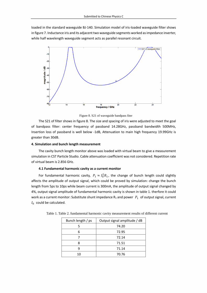
The S21 of filter shows in figure 8. The size and spacing of iris were adjusted to meet the goal
of bandpass filter: center frequency of passband 14.28GHz, passband bandwidth 500MHz,
Insertion loss of passband is well below -1dB, Attenuation to main high frequency 19.99GHz is
greater than 30dB.
4. Simulation and bunch length measurement
The cavity bunch length monitor above was loaded with virtual beam to give a measurement
simulation in CST Particle Studio. Cable attenuation coefficient was not considered. Repetition rate
of virtual beam is 2.856 GHz.
4.1 Fundamental harmonic cavity as a current monitor
For fundamental harmonic cavity, 𝑃1 ≈ 𝐼02𝑅1 , the change of bunch length could slightly
affects the amplitude of output signal, which could be proved by simulation: change the bunch
length from 5ps to 10ps while beam current is 300mA, the amplitude of output signal changed by
4%, output signal amplitude of fundamental harmonic cavity is shown in table 1. therfore it could
work as a current monitor: Substitute shunt impedance R1 and power 𝑃1 of output signal, current
𝐼0 could be calculated.
Table 1. Table 2. fundamental harmonic cavity measurement results of different current
Bunch length / ps Output signal amplitude / dB
5 74.20
6 72.95
7 72.14
8 71.51
9 71.14
10 70.76
Figure 8. S21 of waveguide bandpass fiter

Submitted to Chinese Physics C
Change the current from 100mA to 300mA while bunch length is 10ps, output signal of
fundamental harmonic cavity is shown in figure 9. Vertical coordinate represents normalized
electromagnetic field signal intensity. The signal waveform is composed by two section: ascending
section and equilibrium section. Cavity, as a high impedance structure, would generate power 𝑃1
while beam passed. The energy of electromagnetic field gradually increase. The power coupling
out 𝑃𝑜𝑢𝑡 is proportional to field energy by coefficient 1 𝑄⁄ 𝑒. In the ascending section, 𝑃1 > 𝑃𝑜𝑢𝑡,
field energy and 𝑃𝑜𝑢𝑡 grow synchronously. Until equilibrium is reached: field energy stabilize and
𝑃1 = 𝑃𝑜𝑢𝑡. The calculation results is shown in table 2 compared with current.
Beam current / mA Measurement results / mA Error
100 100.3 0.30%
150 150.5 0.33%
200 199.7 0.15%
250 250.1 0.04%
300 299.8 0.07%
Table 2. fundamental harmonic cavity measurement results of different current
The spectrum of output signal after filter is a individual peak which center frequency is 2.856
GHz, therefore, amplitude of output signal could accurately reflect the change of beam current.
4.2 Fifth harmonic cavity as a bunch length monitor
Change the bunch length from 5 ps to 10 ps while current is 200mA, output signal of fifth
harmonic cavity is shown in figure 10. Vertical coordinate represents normalized electromagnetic
field signal intensity. Spectrum of output signal after filter is a individual peak which center
frequency is 14.28GHz. substitute power of output signal 𝑃1 and 𝑃5 to equation (5), bunch
length could be solved. The calculation results is shown in table 3 compared with theoretical bunch
Figure 9. output signal of fundamental harmonic cavity(current from 100mA to 300mA)
Figure 10. output signal of fifth harmonic cavity (bunch length from 5ps to 10ps)
Submitted to Chinese Physics C
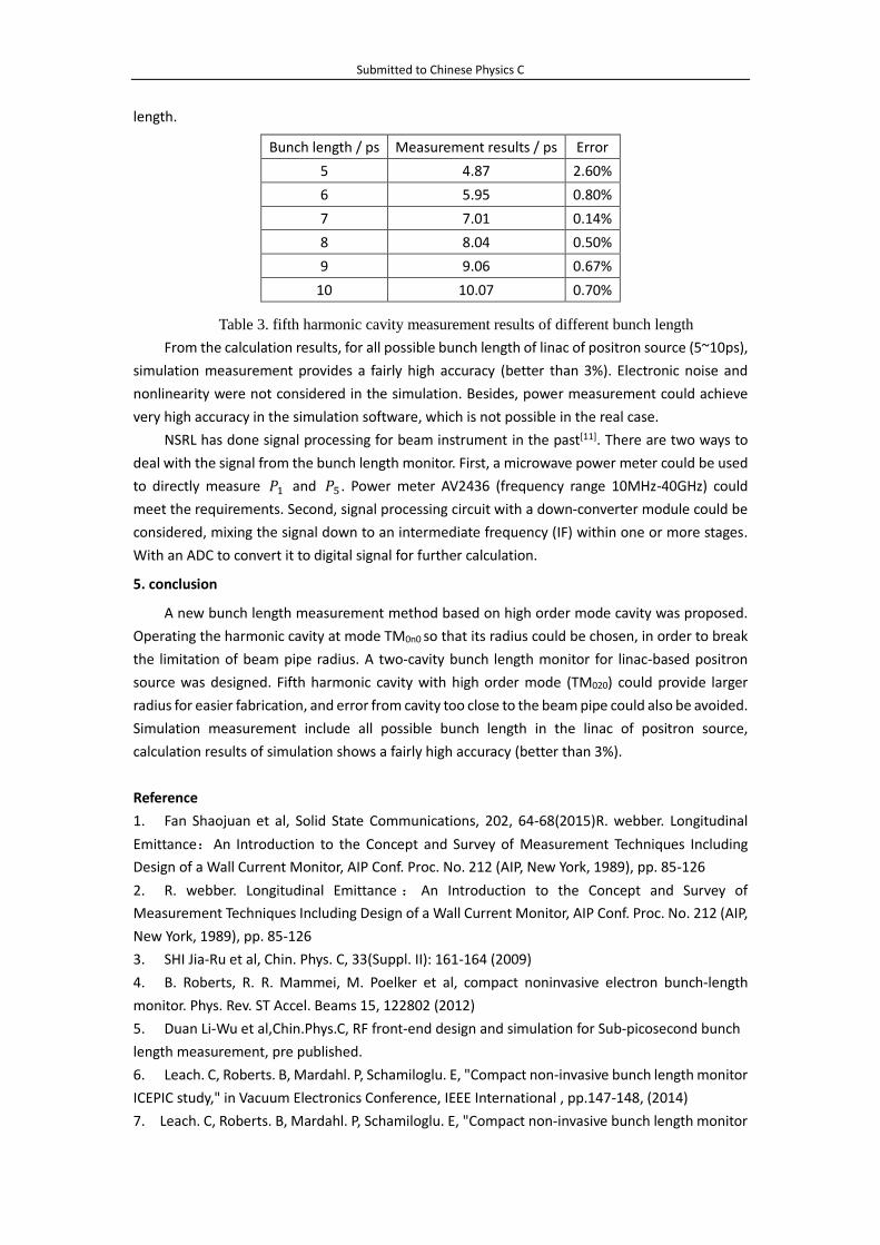
length.
Table 3. fifth harmonic cavity measurement results of different bunch length
From the calculation results, for all possible bunch length of linac of positron source (5~10ps),
simulation measurement provides a fairly high accuracy (better than 3%). Electronic noise and
nonlinearity were not considered in the simulation. Besides, power measurement could achieve
very high accuracy in the simulation software, which is not possible in the real case.
NSRL has done signal processing for beam instrument in the past[11]. There are two ways to
deal with the signal from the bunch length monitor. First, a microwave power meter could be used
to directly measure 𝑃1 and 𝑃5 . Power meter AV2436 (frequency range 10MHz-40GHz) could
meet the requirements. Second, signal processing circuit with a down-converter module could be
considered, mixing the signal down to an intermediate frequency (IF) within one or more stages.
With an ADC to convert it to digital signal for further calculation.
5. conclusion
A new bunch length measurement method based on high order mode cavity was proposed.
Operating the harmonic cavity at mode TM0n0 so that its radius could be chosen, in order to break
the limitation of beam pipe radius. A two-cavity bunch length monitor for linac-based positron
source was designed. Fifth harmonic cavity with high order mode (TM020) could provide larger
radius for easier fabrication, and error from cavity too close to the beam pipe could also be avoided.
Simulation measurement include all possible bunch length in the linac of positron source,
calculation results of simulation shows a fairly high accuracy (better than 3%).
Reference
1. Fan Shaojuan et al, Solid State Communications, 202, 64-68(2015)R. webber. Longitudinal
Emittance:An Introduction to the Concept and Survey of Measurement Techniques Including
Design of a Wall Current Monitor, AIP Conf. Proc. No. 212 (AIP, New York, 1989), pp. 85-126
2. R. webber. Longitudinal Emittance : An Introduction to the Concept and Survey of
Measurement Techniques Including Design of a Wall Current Monitor, AIP Conf. Proc. No. 212 (AIP,
New York, 1989), pp. 85-126
3. SHI Jia-Ru et al, Chin. Phys. C, 33(Suppl. II): 161-164 (2009)
4. B. Roberts, R. R. Mammei, M. Poelker et al, compact noninvasive electron bunch-length
monitor. Phys. Rev. ST Accel. Beams 15, 122802 (2012)
5. Duan Li-Wu et al,Chin.Phys.C, RF front-end design and simulation for Sub-picosecond bunch
length measurement, pre published.
6. Leach. C, Roberts. B, Mardahl. P, Schamiloglu. E, "Compact non-invasive bunch length monitor
ICEPIC study," in Vacuum Electronics Conference, IEEE International , pp.147-148, (2014)
7. Leach. C, Roberts. B, Mardahl. P, Schamiloglu. E, "Compact non-invasive bunch length monitor
Bunch length / ps Measurement results / ps Error
5 4.87 2.60%
6 5.95 0.80%
7 7.01 0.14%
8 8.04 0.50%
9 9.06 0.67%
10 10.07 0.70%

Submitted to Chinese Physics C
ICEPIC study," in Vacuum Electronics Conference, IEEE International , pp.147-148, (2014)
8. CUI Yan-yan et al, High Power Laser and Particle Beams, 2005, 17(12): 1901-1904 (in Chinese)
9. Kaljuzhny, V E, Kostin, D V, Sobenin, N P, et al. Device For The Electron Bunch Length
Measurement of 1-5 mm Rms. Proceedings Of The 1997 Particle Accelerator Conference.
Canada. IPAC. 1997.
10. A.li E, Atia, A;bert E.Williams. Narrow-Bandpass Waveguide Filters, IEEE Trans, Micrewave
Theory Tech, July, 1971(18):258-265
11. YANG Yong-Liang, Ma Tian-Ji, SUN Bao-Gen, WangJi-Gang, Zou Jun-Ying, Cheng Chao-Cai, Lu
Ping. A study of pickup and signal processing for HLS-II bunch current measurement system.
Chinese Physics C, 2013.9, 37(9): 097006-1~097006-4(SCI WOS: 000323996000014)