design and implimentation of monitoring and controlling three-phase
TRANSCRIPT
Volume I, Issue III, August 2014 IJRSI ISSN 2321 – 2705
www.rsisinternational.org/IJRSI.html Page 35
Design and Implementation of Monitoring and Controlling
Three-Phase Multi-Motor Drive Systems in Gantry Cranes
Using PLC and SCADA
Vijaykumar V Dr. Sidheshwar Prasad The Oxford College of Engineering, banglore Professor, Dept EEE, TOCE Banglore
Abstract— Gantry cranes are typically used for moving
containers, loading trucks or material storage anywhere.
Depending upon the capacity of crane, each has multi-
motor drive to describe the technological processes. This
presents crane with multi-motor drive systems for
conducting full operation with its distinct movement. PLC
program is used to control three-motors as per the
movement of weights of operation. SCADA is used as a
communication tool between the client, PLC, and other
control operations. The MICROMASTER420 drive is used
to control the speed of motors and data acquisition. It
shows that load distribution among several motors is
realized by using speed trim configuration. The proportion
load sharing controller has been used to compare the actual
torque signals of the drives and generate an error signals
used for speed trim.
Keywords — PLC program, AC Drive system, SCADA picture
design, multi-motor drive system.
I. INTRODUCTION
crane is the type of machine mainly used for
handling heavy loads in different industry branches:
metallurgy, paper and cement industry. By the
construction, cranes are divided into overhead cranes
and gantry cranes. Overhead and gantry cranes are
typically used for moving containers, loading trucks or
material storage. This crane type usually consists of three
separate motions for transporting material. The first
motion is the hoist, which raises and lowers the material.
The second is the trolley (cross travel), which allows the
hoist to be positioned directly above the material for
placement. The third is the gantry or bridge motion (long
travel), which allows the entire crane to be moved along
the working area[1]. Depending on the crane capacity each of the above
mentioned drives, can be realized as multi-motor drive
system. The term multi-motor drive is used to describe
all the drives in a technological process. If the controlled
operation of the drives is required by the process based
on the controlled speed of the individual drives, the
expression controlled multi-motor drives is adequate. For
many of such drives, the mechanical coupling on the
load side is typical . In applications with cranes, coupling
of the individual motors is realized by the mechanical
transmition device, and it is usually technologically
unbreakable.
This paper presents the loading zone and unloading zone.
Three-motors M1, M2 and M3 are used for
accomplishing movements of gantry crane. PLC used for
controlling the three motors using programs. Drives are
used to control the speed of motors proportional to the
weights. SCADA techniques are used for monitoring and
data acquisition and used as a communicating tool
between the client, PLC and other control systems of the
crane.
Electrical technology for crane control has undergone
a significant change during the last few decades. The
shift from Ward Leonard system to DC drive technology
and the advent of powerful Insulated Gate Bipolar
Transistors (IGBTs) during the 1990s enabled the
introduction of the AC drive [2]. Conventional AC
operated crane drives use slip ring induction motor
whose rotor windings are connected to power resistance
in 4 to 5 steps by power contactors. Reversing is done by
changing the phase sequence of the stator supply through
line contactors. Braking is achieved by plugging. The
main disadvantage is that the actual speed depends on
the load. An electronic control system has recently been
added to continuously control rotor resistor value.
Nowadays, these systems are replaced by frequency
converters supplied squirrel-cage induction motors for all
types of motion. Control concept based on application of
Programmable Logic Controllers (PLC) and industrial
communication networks.
II. BRIEF INTRODUCTION TO PLC AND
SCADA
A digitally operating electronic apparatus which uses a
programming memory for the internal storage of
instructions for implementing specific functions such as
logic, sequencing, timing, counting and arithmetic to
control through digital or analog modules, various types
of machines or process. PROGRAMMABLE Logic
Controller (PLC) is used to control machines and
processes[7]. PLCs can be used with a wide range of
control systems, which vary widely in their nature and
complexity. After programming the PLC, before starting
a real process, the operator has to verify if the program is
correct, i.e. if the PLC correctly performs the predefined
control task. Therefore, the operator monitors the states
at input and output port of the PLC. A usual way is to
Monitor all the states and program variables online,
during the operation of PLC, with the same
programming environment which was used for
programming the PLC. However, it is best to develop a
physical educational model of the system, where the
operator manually enters the inputs of the PLC and
monitors its output states. However, this can take a long
time depending on the complexity of the system. Also,
this solution isn‟t modular because it is difficult to
A
Volume I, Issue III, August 2014 IJRSI ISSN 2321 – 2705
www.rsisinternational.org/IJRSI.html Page 36
rebuild the model if some changes are necessary. The
most complex system for monitoring and control of
industrial processes which is widely used nowadays is
Supervisory Control and Data Acquisition (SCADA)
system . This system requires use of communication
protocols between the client on one side and PLC and
other parts of control system on the other side. Although
the SCADA is standard monitoring and data acquisition
system in industry, it isn‟t easy to make, so it isn‟t
appropriate in simple control systems, when it is
necessary to make a simple cost-effective monitoring
system. The operator uses software simulator to activate
certain inputs of the PLC, while the application receives
the information about output states of the PLC and it
shows them graphically, i.e. in animation. This process is
realized through interface board which communicates
with PC and controls/reads input/output ports of the
PLC.
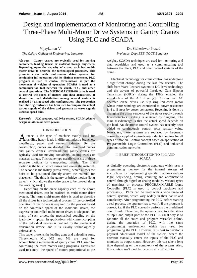
Fig 1.Major Components of a Common PLC
POWER SUPPLY Provides the voltage needed to run the primary PLC
components
I/O MODULES Provides signal conversion and isolation between the
internal logic- level signals inside the PLC and the
field‟s high level signal.
PROCESSOR Provides intelligence to command and govern the
activities of the entire PLC systems.
PROGRAMMING DEVICE Used to enter the desired program that will determine the
sequence of operation and control of process equipment
or driven machine.
Advantages of PLCs
1. Less wiring
2. Wiring between devices and relay contacts are done in
the PLC program.
3. Easier and faster to make changes.
4. Trouble shooting aids make programming easier and
reduce downtime.
5. Reliable components make these likely to operate for
years before failure.
III. GANTRY CRANE DRIVE SYSTEM AND ITS
APPLICATIONS
Controlled drives are usually fed from the power
converter, which is also true for controlled multi-motor
drives. The kind, the type and the number of converters
used depend on the type of motors, their power ratings,
and of the kind of the multi-motor drive. The following
cases are possible :
a) Multiple motors fed by a single converter (multiple
motors - single converter),
b) Motors controlled by separate converters (multiple
motors - multiple converters).
In crane applications multi-motor drives are used very
often and a proportional share of power between motors
is required. Load sharing is a term used to describe a
system where multiple converters and motors are
coupled and used to run one mechanical load. For the
squirrel cage induction motors, there is no economical
method for the adjustment of the mechanical
characteristic of the ready-made motors, but this has to
be done during the selection. For the slip-ring induction
motor, the mechanical characteristic can be adjusted
afterwards, with the inclusion of the rotor resistors.
Motors that are controlled by separate converters without
any interconnection also do not share the load. Control
topologies for load sharing consider the presence of
interconnection, i.e. information knowledge about load
(motor current or torque). There are three categories of
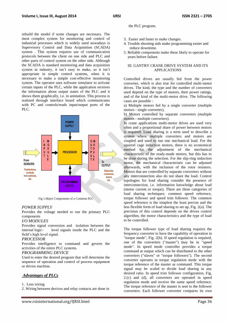
load sharing techniques: common speed reference,
torque follower and speed trim follower. The common
speed reference is the simplest the least precise and the
less flexible form of load sharing to set up, Fig. 2(a). The
precision of this control depends on the drives control
algorithm, the motor characteristics and the type of load
to be controlled.
The torque follower type of load sharing requires the
frequency converter to have the capability of operation in
"torque mode", Fig. 2(b). If speed regulation is required,
one of the converters ("master") may be in "speed
mode". In speed mode controller provides a torque
command at output which can be distributed to the other
converters ("slaves" or "torque followers"). The second
converter operates in torque regulation mode with the
torque reference of the master as command. This torque
signal may be scaled to divide load sharing in any
desired ratio. In speed trim follower configuration, Fig.
2.(c) and (d), all converters are operated in speed
regulation mode and receive the same speed reference.
The torque reference of the master is sent to the follower
converters. Each follower converter compares its own
Volume I, Issue III, August 2014 IJRSI ISSN 2321 – 2705
www.rsisinternational.org/IJRSI.html Page 37
torque reference with that of the master, Fig. 2.(c). The
output of the comparator is an error signal that trims the
speed of the follower. Alternative configuration cascades
the torque reference comparison, Fig. 2.(d). The first
follower compares the master to its internal value. The
second follower compares the foregoing follower to its
internal value etc.
Fig.2. Load sharing configuration( a) Common speed reference,( b)
Torque follower,( c) and (d) Speed trim follower.
a) Torque and power requirements for crane
drives:
Speed control is an essential feature in crane drives. It is
required for allowing soft starting and stopping of the
travel motions for enabling its correct positioning of
load. For the lifting drive the speed control in a wide
speed range, from zero to nominal values, is required.
Because of the precision when raising and lowering load,
the possibility of working at a very low speed and hold a
load in the standstill is required, without using the
mechanical brakes. The torque and power that have to be
delivered by the drive may be obtained from the torque
versus speed characteristic from the load (so-called
mechanical characteristics) and the differential equation
of motion. The differential equation of motion,
describing the behavior of the drive is:
where Te is the electromagnetic torque of the
motor, Tl is the torque of the load, J is the
inertia of the drive. If Te > Tl, the system
accelerates (dω/dt > 0), if Tl/Te < 0 it
decelerates (dω/dt>0). The stedy state operation
is reached if Tl = Te and ω= const.
Multiplying equation (1) by the rotating speed ω,
yields the power:
This equation shows that the mechanical power
Pe=ωTe, obtained after the electromechanical
conversion in the motor, is equal to the power
absorbed by the load Pm=ωTl only when the speed
does not change. Otherwise, the amount
corresponding to change in kinetic energy must be
added (if the speed increases) or subtracted (if the
speed decreases):
In the following, the travel and hoist motion of the crane
drives will be analyzed.
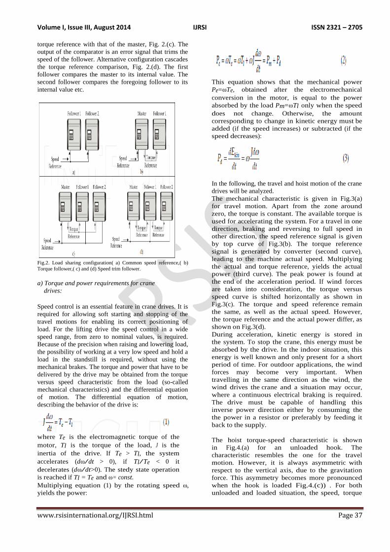
The mechanical characteristic is given in Fig.3(a)
for travel motion. Apart from the zone around
zero, the torque is constant. The available torque is
used for accelerating the system. For a travel in one
direction, braking and reversing to full speed in
other direction, the speed reference signal is given
by top curve of Fig.3(b). The torque reference
signal is generated by converter (second curve),
leading to the machine actual speed. Multiplying
the actual and torque reference, yields the actual
power (third curve). The peak power is found at
the end of the acceleration period. If wind forces
are taken into consideration, the torque versus
speed curve is shifted horizontally as shown in
Fig.3(c). The torque and speed reference remain
the same, as well as the actual speed. However,
the torque reference and the actual power differ, as
shown on Fig.3(d).
During acceleration, kinetic energy is stored in
the system. To stop the crane, this energy must be
absorbed by the drive. In the indoor situation, this
energy is well known and only present for a short
period of time. For outdoor applications, the wind
forces may become very important. When
travelling in the same direction as the wind, the
wind drives the crane and a situation may occur,
where a continuous electrical braking is required.
The drive must be capable of handling this
inverse power direction either by consuming the
the power in a resistor or preferably by feeding it
back to the supply.
The hoist torque-speed characteristic is shown
in Fig.4.(a) for an unloaded hook. The
characteristic resembles the one for the travel
motion. However, it is always asymmetric with
respect to the vertical axis, due to the gravitation
force. This asymmetry becomes more pronounced
when the hook is loaded Fig.4.(c)) . For both
unloaded and loaded situation, the speed, torque
Volume I, Issue III, August 2014 IJRSI ISSN 2321 – 2705
www.rsisinternational.org/IJRSI.html Page 38
and power are given in Fig.4.(b) and Fig.4(d).
Again the amount of braking power is indicated.
The worst braking case with a hoist motion, is
when sinking a loaded hook. It should be noted
that the weight of the hook may be considerable.
The hook may be simple, or may consist of several
parts to handle the load. For the hoist motion, the
speed
Fig.3. Power and torque requirements for travel motion, a) and b)
without wind influence, c) and d) with wind influence.
Fig. 4. Power and torque requirements for hoist a) and b) without load, c) and d) with load.
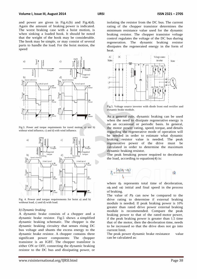
b) Dynamic braking
A dynamic brake consists of a chopper and a
dynamic brake resistor. Fig.5 shows a simplified
dynamic braking schematic. The chopper is the
dynamic braking circuitry that senses rising DC
bus voltage and shunts the excess energy to the
dynamic brake resistor. A chopper contains three
significant power components: The chopper
transistor is an IGBT. The chopper transistor is
either ON or OFF, connecting the dynamic braking
resistor to the DC bus and dissipating power, or
isolating the resistor from the DC bus. The current
rating of the chopper transistor determines the
minimum resistance value used for the dynamic
braking resistor. The chopper transistor voltage
control regulates the voltage of the DC bus during
regeneration. The dynamic braking resistor
dissipates the regenerated energy in the form of
heat.
Fig.5. Voltage source inverter with diode front end rectifier and
dynamic brake module.
As a general rule, dynamic braking can be used
when the need to dissipate regenerative energy is
on an occasional or periodic basis. In general,
the motor power rating, speed, torque, and details
regarding the regenerative mode of operation will
be needed in order to estimate what dynamic
braking resistor value is needed. The peak
regenerative power of the drive must be
calculated in order to determine the maximum
dynamic braking resistor.
The peak breaking power required to decelerate
the load, according to equation(4) is:
where tb represents total time of deceleration,
ωb and ω0 initial and final speed in the process
of braking.
The value of Pb can now be compared to the
drive rating to determine if external braking
module is needed. If peak braking power is 10%
greater than rated drive power external braking
module is recommended. Compare the peak
braking power to that of the rated motor power,
if the peak braking power is greater than 1.5 time
that of the motor, then the deceleration time, needs
to be increased so that the drive does not go into
current limit.
The peak power dynamic brake resistance value
can be calculated as: 2
Volume I, Issue III, August 2014 IJRSI ISSN 2321 – 2705
www.rsisinternational.org/IJRSI.html Page 39
The choice of the dynamic brake resistance value should
be less than the value calculated by equation (5). If a
dynamic braking resistance value greater than the ones
imposed by the choice of the peak regenerative power is
made and applied, the drive can trip off due to transient
DC bus overvoltage problems. Once the approximate
resistance value of the dynamic braking resistor is
determined, the necessary power rating of the dynamic
braking resistor can be calculated. The power rating of
the dynamic braking resistor is estimated by applying
what is known about the drive‟s motoring and
regenerating modes of operation.
To calculate the average power dissipation the
braking duty cycle must be determined. The
percentage of time during an operating cycle (tc)
when braking occurs (tb) is duty cycle (ω=tb/tc).
Assuming the deceleration rate is linear, average
power is calculated as follows:
Fig.6.(a) shows the experimental results (DC
voltage and chopper current) for the variable
frequency drive with braking module in DC link
and external braking resistor, under a step change
of induction motor load in regenerative regime.
Frequency (series VLT 5000) converter is used in
experimental set-up. For the supply voltage of 400
V, DC link voltage is about 540 V. When negative
load torque is applied, DC link voltage rises.
The chopper transistor voltage control regulates
the voltage of the DC bus during regeneration to
near 800 V allowing current flow in the resistor.
Regenerative energy is then realised into heat.
After the end of the regenerative period, DC
voltage returns to a value that corresponds to a
motor regime. The Fig.6(b) shows the line voltage
and current at the input of the diode rectifier.
Fig. 6. (a) DC voltage and chopper current, (b) line voltage and
current.
A voltage source PWM inverter with diode front-
end rectifier is one of the most common power
configurations used in modem variable speed AC
drives, (Fig.4). An uncontrolled diode rectifier has
the advantage of being simple, robust, and low
cost. However, it allows only unidirectional
power flow. Therefore, energy returned from
the motor must be dissipated on a power
resistor controlled by a chopper connected across
the dc link. A further restriction is that the
maximum motor output voltage is always less than
the supply voltage.
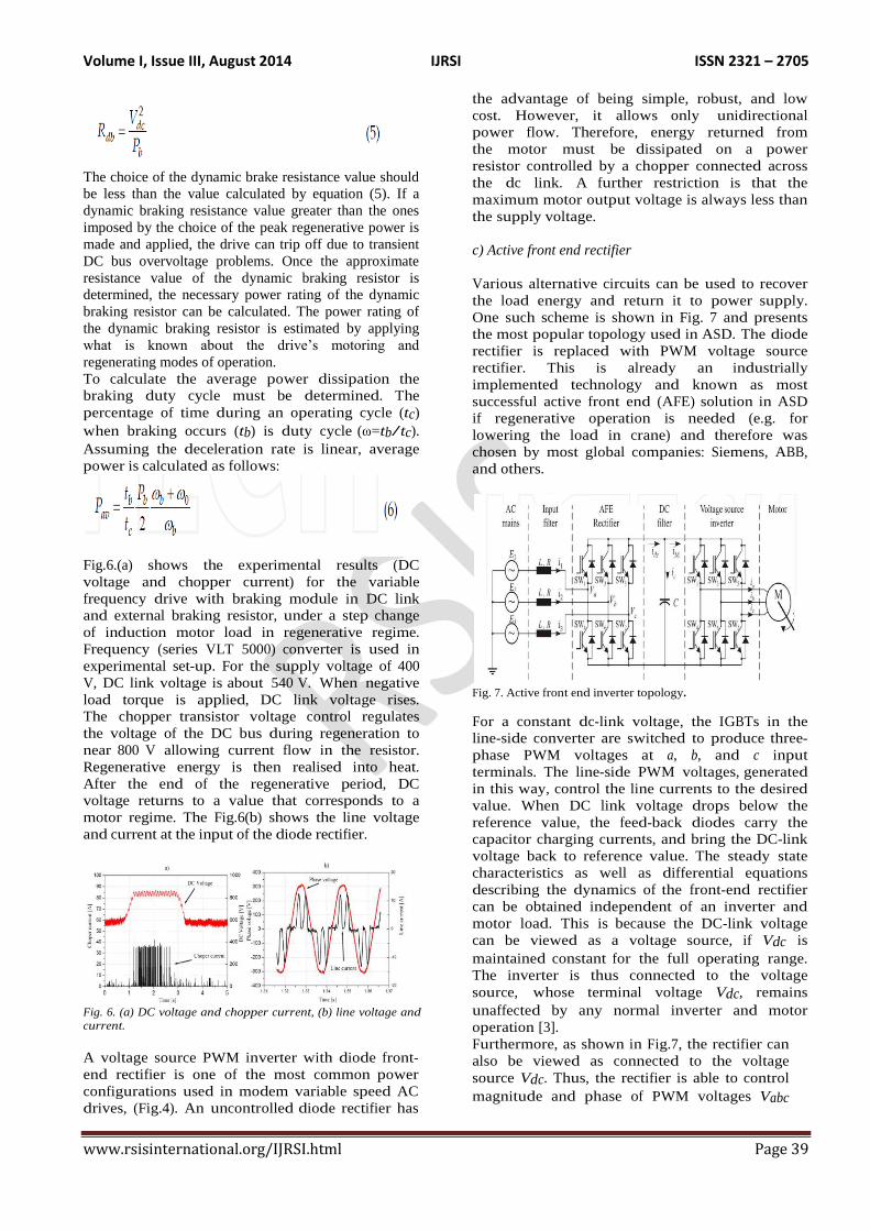
c) Active front end rectifier
Various alternative circuits can be used to recover
the load energy and return it to power supply.
One such scheme is shown in Fig. 7 and presents
the most popular topology used in ASD. The diode
rectifier is replaced with PWM voltage source
rectifier. This is already an industrially
implemented technology and known as most
successful active front end (AFE) solution in ASD
if regenerative operation is needed (e.g. for
lowering the load in crane) and therefore was
chosen by most global companies: Siemens, ABB,
and others.
Fig. 7. Active front end inverter topology.
For a constant dc-link voltage, the IGBTs in the
line-side converter are switched to produce three-
phase PWM voltages at a, b, and c input
terminals. The line-side PWM voltages, generated
in this way, control the line currents to the desired
value. When DC link voltage drops below the
reference value, the feed-back diodes carry the
capacitor charging currents, and bring the DC-link
voltage back to reference value. The steady state
characteristics as well as differential equations
describing the dynamics of the front-end rectifier
can be obtained independent of an inverter and
motor load. This is because the DC-link voltage
can be viewed as a voltage source, if Vdc is
maintained constant for the full operating range.
The inverter is thus connected to the voltage
source, whose terminal voltage Vdc, remains
unaffected by any normal inverter and motor
operation [3].
Furthermore, as shown in Fig.7, the rectifier can
also be viewed as connected to the voltage
source Vdc. Thus, the rectifier is able to control
magnitude and phase of PWM voltages Vabc
Volume I, Issue III, August 2014 IJRSI ISSN 2321 – 2705
www.rsisinternational.org/IJRSI.html Page 40
irrespective of line voltages E123. The dynamic
equations for each phase can be written as,
In synchronous rotating d-q reference frame
Equations 8 and 9 represent the dynamic d-q
model of an active front end inverter in a
reference frame rotating at an angular speed of ω.
The differential equation governing DC link
voltage also needs to be added to the above set of
system equations to completely define system
dynamics:
where, idc is the total DC link current supplied by
the rectifier, while iM is the load-side DC current
which is the result of induction motor operation.
In Equations (8) and (9), the terms Eqe and Ede are
computed from source voltages, E1, E2, and E3.
Since line voltages are known, the angular
frequency ω , can be easily estimated. The PWM
voltages Vqe and Vde are the two inputs to the
system which are generated using the sine-
triangle PWM controller. L and R represent series
impedance.
Equations (8) and (9) shows that d-q current is
related with both coupling voltages ωLiq and ωLid,
and main voltage Ed nd Eq, besides the influence
of PWM voltage Vqe and Vde. Voltage Vqe and
Vde are the inputs, controlled in such a way as to
generate desired currents. Now define new
variables V'qe and V'de such that
So that the new system dynamic equations
become:
We can see from equations that the two axis
current are totally decoupled because V'qe and
V'de are only related with iqe and ide respectively.
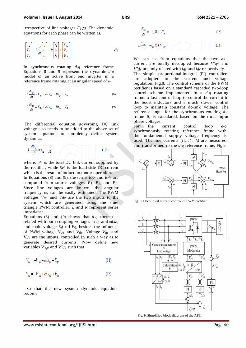
The simple proportional-integral (PI) controllers
are adopted in the current and voltage
regulation, Fig.8. The control scheme of the PWM
rectifier is based on a standard cascaded two-loop
control scheme implemented in a d-q rotating
frame: a fast control loop to control the current in
the boost inductors and a much slower control
loop to maintain constant dc-link voltage. The
reference angle for the synchronous rotating d-q
frame θ, is calculated, based on the three input
phase voltages.
For the current control loop d-q
synchronously rotating reference frame with
the fundamental supply voltage frequency is
used. The line currents (i1, i2, i3) are measured
and transformed to the d-q reference frame, Fig.9.
Fig. 8. Decoupled current control of PWM rectifier.
Fig. 9. Simplified block diagram of the AFE
Volume I, Issue III, August 2014 IJRSI ISSN 2321 – 2705
www.rsisinternational.org/IJRSI.html Page 41
To get information about the position of the line
voltage vector PLL (phase locked loop) is
implemented. PI controllers for the d-q
components of line current are identical and ωL
terms are included to eliminate the coupling effect
among the d and q components. Outputs of the line
current PI controllers present d and q components
of the voltage across the line inductance.
Subtracting this voltage from the supply voltage
gives the converter voltage from the AC side
that is used to get the modulation signal for
proper switching of six switching devices. The
main task of the sinusoidal front end is to operate
with the sinusoidal line current; so d and q
components of the line current reference are DC
values. Using this approach of control it is possible
to control the output voltage of converter as
well as the power factor of converter in the
same time. To achieve unity power factor the
reference of q current component need to be set
on zero.
IV. AC DRIVES SYSTEM
An adjustable speed drive is a device that controls speed,
and direction of an AC or DC motor. Some high
performance drives are able to run in torque regulation
mode. The speed of an AC motor is determined for the
most part by two factors: The applied frequency and the
number of poles. An adjustable frequency AC drive
system consists of an ordinary three-phase induction
motor, an adjustable frequency drive to control the speed
of the motor and an operator's control station. The
adjustable frequency controller is a solid-state power
conversion unit. It receives 240 or 480 volt, 3-phase, 60
Hz power and converts it to a variable frequency supply
which can be steplessly adjusted between 0 and 60 Hz.
The controller also adjusts the output voltage in
proportion to the frequency to provide a nominally
constant ratio of voltage to frequency as required by the
characteristics of the motor. The operator's station
provides the operator with the necessary controls for
starting and stopping the motor and varying the motor
speed. These functions can also be performed by a wide
variety of automatic control systems.
In this project, for prototype purpose we are
using three-phase inductive load which is run by a
single-phase supply by using cyclo converter and a
Scott-T connected Transformer. Two-phase motors
draw constant power the same as three-phase motors, so
a balanced two-phase load is converted to a balanced
three-phase load.
a) Basic Principles of AC Drive Operation
There are several classifications of adjustable
frequency AC drives. Some common types of drives are
Variable Voltage Input (VVI) sometimes called Six Step
drives, current source input (CSI), pulse width
modulated (PWM) drives, Sensorless Vector drives,
Field Oriented drives and Closed Loop Vector drives.
The more common AC drives are PWM, Sensorless
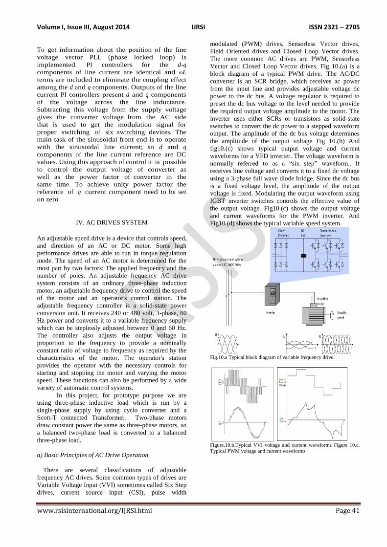
Vector and Closed Loop Vector drives. Fig 10.(a) is a
block diagram of a typical PWM drive. The AC/DC
converter is an SCR bridge, which receives ac power
from the input line and provides adjustable voltage dc
power to the dc bus. A voltage regulator is required to
preset the dc bus voltage to the level needed to provide
the required output voltage amplitude to the motor. The
inverter uses either SCRs or transistors as solid-state
switches to convert the dc power to a stepped waveform
output. The amplitude of the dc bus voltage determines
the amplitude of the output voltage Fig 10.(b) And
fig10.(c) shows typical output voltage and current
waveforms for a VFD inverter. The voltage waveform is
normally referred to as a “six step” waveform.. It
receives line voltage and converts it to a fixed dc voltage
using a 3-phase full wave diode bridge. Since the dc bus
is a fixed voltage level, the amplitude of the output
voltage is fixed. Modulating the output waveform using
IGBT inverter switches controls the effective value of
the output voltage. Fig10.(c) shows the output voltage
and current waveforms for the PWM inverter. And
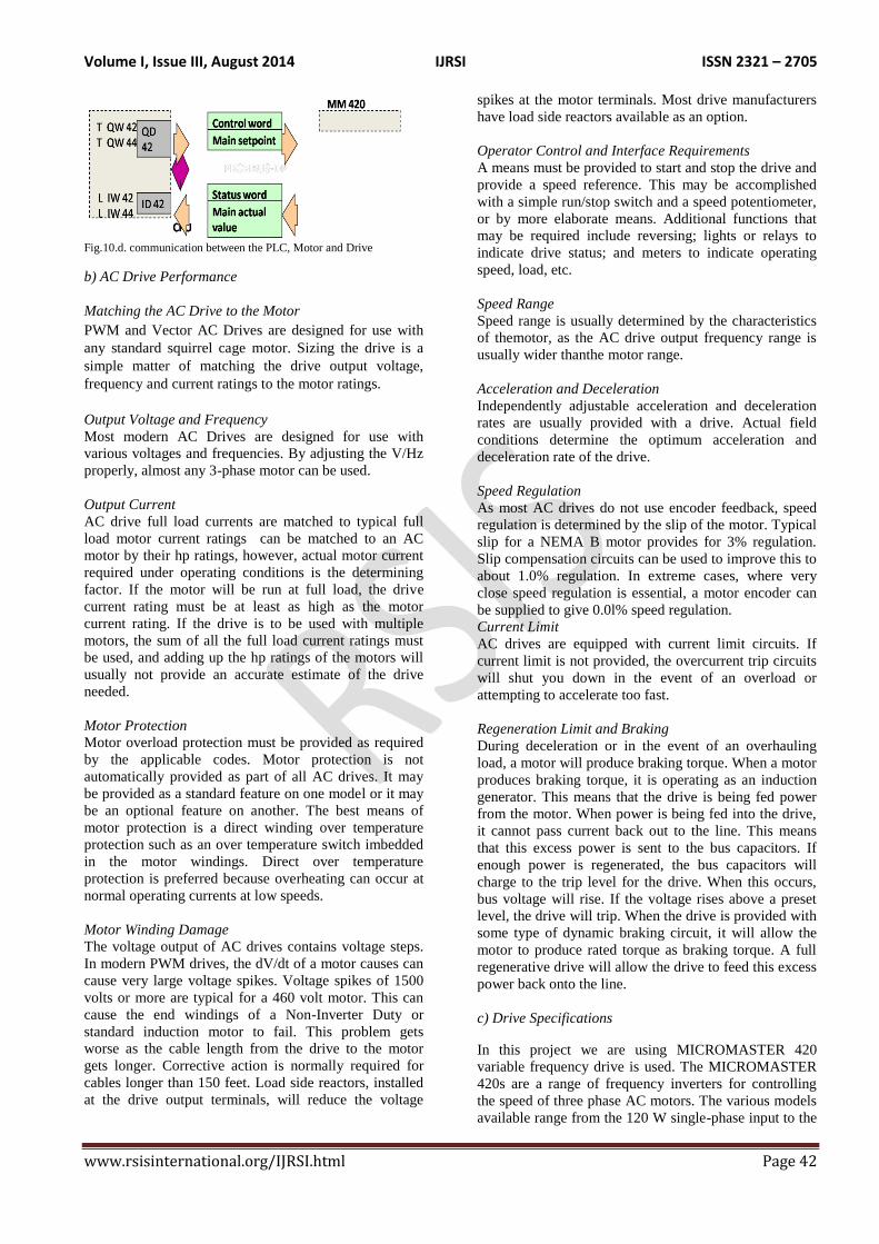
Fig10.(d) shows the typical variable speed system.
Fig.10.a Typical block diagram of variable frequency drive
Figure.10.b.Typical VVI voltage and current waveforms Figure 10.c.
Typical PWM voltage and current waveforms
Volume I, Issue III, August 2014 IJRSI ISSN 2321 – 2705
www.rsisinternational.org/IJRSI.html Page 42
Fig.10.d. communication between the PLC, Motor and Drive
b) AC Drive Performance
Matching the AC Drive to the Motor
PWM and Vector AC Drives are designed for use with
any standard squirrel cage motor. Sizing the drive is a
simple matter of matching the drive output voltage,
frequency and current ratings to the motor ratings.
Output Voltage and Frequency
Most modern AC Drives are designed for use with
various voltages and frequencies. By adjusting the V/Hz
properly, almost any 3-phase motor can be used.
Output Current
AC drive full load currents are matched to typical full
load motor current ratings can be matched to an AC
motor by their hp ratings, however, actual motor current
required under operating conditions is the determining
factor. If the motor will be run at full load, the drive
current rating must be at least as high as the motor
current rating. If the drive is to be used with multiple
motors, the sum of all the full load current ratings must
be used, and adding up the hp ratings of the motors will
usually not provide an accurate estimate of the drive
needed.
Motor Protection
Motor overload protection must be provided as required
by the applicable codes. Motor protection is not
automatically provided as part of all AC drives. It may
be provided as a standard feature on one model or it may
be an optional feature on another. The best means of
motor protection is a direct winding over temperature
protection such as an over temperature switch imbedded
in the motor windings. Direct over temperature
protection is preferred because overheating can occur at
normal operating currents at low speeds.
Motor Winding Damage
The voltage output of AC drives contains voltage steps.
In modern PWM drives, the dV/dt of a motor causes can
cause very large voltage spikes. Voltage spikes of 1500
volts or more are typical for a 460 volt motor. This can
cause the end windings of a Non-Inverter Duty or
standard induction motor to fail. This problem gets
worse as the cable length from the drive to the motor
gets longer. Corrective action is normally required for
cables longer than 150 feet. Load side reactors, installed
at the drive output terminals, will reduce the voltage
spikes at the motor terminals. Most drive manufacturers
have load side reactors available as an option.
Operator Control and Interface Requirements
A means must be provided to start and stop the drive and
provide a speed reference. This may be accomplished
with a simple run/stop switch and a speed potentiometer,
or by more elaborate means. Additional functions that
may be required include reversing; lights or relays to
indicate drive status; and meters to indicate operating
speed, load, etc.
Speed Range
Speed range is usually determined by the characteristics
of themotor, as the AC drive output frequency range is
usually wider thanthe motor range.
Acceleration and Deceleration
Independently adjustable acceleration and deceleration
rates are usually provided with a drive. Actual field
conditions determine the optimum acceleration and
deceleration rate of the drive.
Speed Regulation
As most AC drives do not use encoder feedback, speed
regulation is determined by the slip of the motor. Typical
slip for a NEMA B motor provides for 3% regulation.
Slip compensation circuits can be used to improve this to
about 1.0% regulation. In extreme cases, where very
close speed regulation is essential, a motor encoder can
be supplied to give 0.0l% speed regulation.
Current Limit
AC drives are equipped with current limit circuits. If
current limit is not provided, the overcurrent trip circuits
will shut you down in the event of an overload or
attempting to accelerate too fast.
Regeneration Limit and Braking
During deceleration or in the event of an overhauling
load, a motor will produce braking torque. When a motor
produces braking torque, it is operating as an induction
generator. This means that the drive is being fed power
from the motor. When power is being fed into the drive,
it cannot pass current back out to the line. This means
that this excess power is sent to the bus capacitors. If
enough power is regenerated, the bus capacitors will
charge to the trip level for the drive. When this occurs,
bus voltage will rise. If the voltage rises above a preset
level, the drive will trip. When the drive is provided with
some type of dynamic braking circuit, it will allow the
motor to produce rated torque as braking torque. A full
regenerative drive will allow the drive to feed this excess
power back onto the line.
c) Drive Specifications
In this project we are using MICROMASTER 420
variable frequency drive is used. The MICROMASTER
420s are a range of frequency inverters for controlling
the speed of three phase AC motors. The various models
available range from the 120 W single-phase input to the
Volume I, Issue III, August 2014 IJRSI ISSN 2321 – 2705
www.rsisinternational.org/IJRSI.html Page 43
11 kW three-phase input. The inverters are
microprocessor-controlled and use state-of-the-art
Insulated Gate BipoIar Transistor (IGBT) technology.
This makes them reliable and versatile. A special pulse-
width modulation method with selectable Pulse
frequency permits quiet motor operation.
Comprehensive protective functions provide excellent
inverter and motor protection. The MICROMASTER
420 with its default factory settings, is ideal for a large
range of simple motor control applications. The
MICROMASTER 420 can also be used for more
advanced motor control applications via its
comprehensive parameter lists. The MICROMASTER
420 can be used in both 'stand-alone' applications as well
as being integrated into 'Automation Systems'.
Adjustable linear acceleration and deceleration are
provided, making the drive suitable for soft start
applications. The output voltage is sinewave coded
PWM operating at 16 kHz, which provides high motor
torque, high efficiency, and low noise. The full featured
drive is easy to install and operate. Simple trimpot
adjustments eliminate the computer-like programming
required on other drives. However, for most applications,
no adjustments are necessary.
Table 1 – Electrical Ratings
Input volts 115 or 230 v AC +/- 10%,
single phase, 50/60Hz
Input Current 11.0 (115v) or 7.0 (230v)
Amps AC
Output volts 0-230 v AC, three phase
Output current, per phase 2.4 Amps RMS
d) Features of drive
Main Characteristics
1. Easy installation
2. Easy commissioning
3. Rugged EMC design
4. Can be operated on IT line supplies
5. Fast repeatable response time to control signals
6. Comprehensive range of parameters enabling
configuration for a wide range of applications
7. Simple cable connection
8. Output relay
Analog output (0 – 20 mA)
9.Isolated and switchable NPN/PNP digital inputs
10. Analog input, ADC: 0 – 10 V
The analog input can be used as the 4th
digital input
11.BICO technology
12.Modular design for extremely flexible
configuration
13. High switching frequencies for low-noise motor
operation
14.Detailed status information and integrated message
functions
Performance Characteristics
1. V/f Control
2. Flux Current Control (FCC) for improved dynamic
response and motor control
3. Multi-point V/f characteristic
4. Automatic restart
5. Flying restart
6. Slip compensation
7. Fast Current Limitation (FCL) for trip-free operation
8. Motor holding brake
9. Built-in DC injection brake
10.Compound braking to improve braking performance
11.Setpoint input via:
Analog input
Communication interface
JOG function
Motorized potentiometer
Fixed frequencies
12. Ramp function generator
With smoothing
Without smoothing
13.Closed-loop control with proportional-integral
controller function
Protection characteristics
Overvoltage/undervoltage protection
Over temperature protection for the
inverter
Ground fault protection
Short-circuit protection
Thermal motor protection
PTC for motor protection
e) Control parameters of the drive
Current
Voltage
Power
Speed
Frequency
Temperature
f) Alarm messages of the drive
AO501 Current limit value
A0502 Overvoltage limit value
A0503 Under voltage limit value
A0504 Inverter over temperature
A0506 Inverter load duty cycle
A0510 Motor over temperature
Volume I, Issue III, August 2014 IJRSI ISSN 2321 – 2705
www.rsisinternational.org/IJRSI.html Page 44
A0520 Rectifier over temperature......etc
g) Benefits of Using AC Drives
AC drives have become very popular in recent years as it
is recognized that they provide a very efficient and direct
method of controlling the speed of the most rugged and
reliable of prime movers, the squirrel cage motor. AC
drives provide many economic and performance
advantages in a wide variety of adjustable speed drive
applications.
The following are some of the benefits provided
1. High efficiency and low operating cost
Minimal motor maintenance
2. Controlled linear acceleration and deceleration
provide soft starting and stopping and smooth
speed changes
3. Multiple motor operation is easily
accomplished
4. Current limit provides for quick and accurate
torque control
5. Adjustable speed operation can be
accomplished with existing AC motors
6. Improved speed regulation can be
accomplished by slip compensation
7. AC motors are available in a wide variety of
mechanical configurations
8. Flexibility of machine design due to the light
weight and compact size of AC motors
9. IR compensation provides high starting torque
easily and economically
10. AC motors are available in enclosures suitable
for hazardous or corrosive environments
11. Fewer spare motors are required since the
same motor can be used for both adjustable
speed and constant speed operations.
12. Cutler-Hammer rugged and reliable designs
ensure minimum downtime expense
13. High speed operation can be economically
accomplished using extended frequency
operation.
14. Reverse operation is accomplished
electronically without the need for a reversing
starter
h) Applications of AC Drives
• Refrigeration Racks
• Air Conditioners
• Walk-in Coolers
• Cooling Towers
• Evaporative Condensers
• Reciprocating Chillers
• Process Water Chillers
• Condensing Units
• Packaged Roof Tops
• Packaged (Water) Chillers
• Computer Room AC
• Environmental (Test) Chambers
i) Requirements of speed control in this project
1. To improve the efficiency of motor-driven equipment by matching speed to changing load requirements;
2. To allow accurate and continuous position
control over a wide range of speeds.
3. Controlled acceleration and deceleration of the
crane hoist
4. Impact loads due to end stops placed on the
crane extreme rotary positions.
5. Off-vertical lifting at the start of hoisting
Tendency of the crane to travel obliquely.
V. MULTIMOTOR DRIVE SYSTEM
In this project we have to Control Multiple Motors with
2 VFD‟s. And One VFD can controlling multi-motors
simultaneously or sequentially.
One VFD can controlling multi-motors simultaneously
The overall control system also becomes much simpler.
Instead of connecting many VFDs to the main controller,
usually a PLC, and synchronizing their operation; only
one connection is required. When programming the PLC,
only one VFD speed control loop needs to be configured,
instead of multiple instances[4].
Design Constraints
1. All motors must operate at same speed
2. Design must accommodate VFD as a single point of
failure
3. VFD must be upsized unless all motors are started
simultaneous
Multiple conditions must be met when applying one
VFD for control of multiple motors. First, each motor
must have the same desired operating speed. With one
VFD per motor, each motor can be controlled separately
and run at a different speed. This is not so when running
multiple motors from one VFD.
Second, running multiple motors from one VFD creates
a single point of failure. If the VFD fails, then all of the
motors connected to it are not usable. Various VFD
bypass schemes can be used to overcome this limitation,
but these schemes all add cost and complexity to the
system. Although the VFD becomes a single point of
failure, motor and connected load reliability actually
improve in many applications as there are now multiple
smaller motors as opposed to one large motor. If one
motor fails, it‟s often possible to continue operation with
the remaining motors. In these cases, the remaining
motors run at a speed controlled by the VFD, and operate
the overall system at reduced but often still viable
capacity. Third, care must be taken when operating the
motors. To minimize VFD size, all motors need to be
Volume I, Issue III, August 2014 IJRSI ISSN 2321 – 2705
www.rsisinternational.org/IJRSI.html Page 45
started up simultaneously. The VFD will ramp all the
motors up to speed at a controlled rate, minimizing the
inrush current required by each motor at startup. If
application requirements prevent all the motors from
being started up simultaneously, then the VFD must be
upsized.
Design Details
The VFD must be sized properly based on its connected
motors. The first step is to sum total connected motor
horsepower or full load amps (FLA). Of the two, FLA is
the better parameter to use, but it‟s sometimes not
available. Once this sum is calculated, selection of the
VFD based on total horsepower or FLA can be made.
The VFD should always be sized equal to or greater than
this sum.
Normal VFD operation will enable all of the connected
motors to maintain a constant speed, but only if the
correct type of motors are used. A standard induction
motor tends to slip somewhat with respect to the line
frequency as its load varies, so speeds won‟t be
synchronous. The solution is to use three-phase, inverter-
duty synchronous induction motors as this ensures that
the motor speeds will remain synchronous with the line
frequency.
Unlike with a single motor connected to a VFD, each
motor must have its own overload and short circuit
protection. When controlling a single motor, a VFD with
the right features can often provide short circuit and
overload protection to the motor, and may be able to
sense an over current situation if the circumstances are
right.
But a VFD only senses its total connected load,
outputting as many amps as needed up to its current
rating. When controlling multiple motors, a single VFD
can‟t sense which motor is drawing high current, so it
can‟t provide appropriate overload and over current
protection to each individual motor.
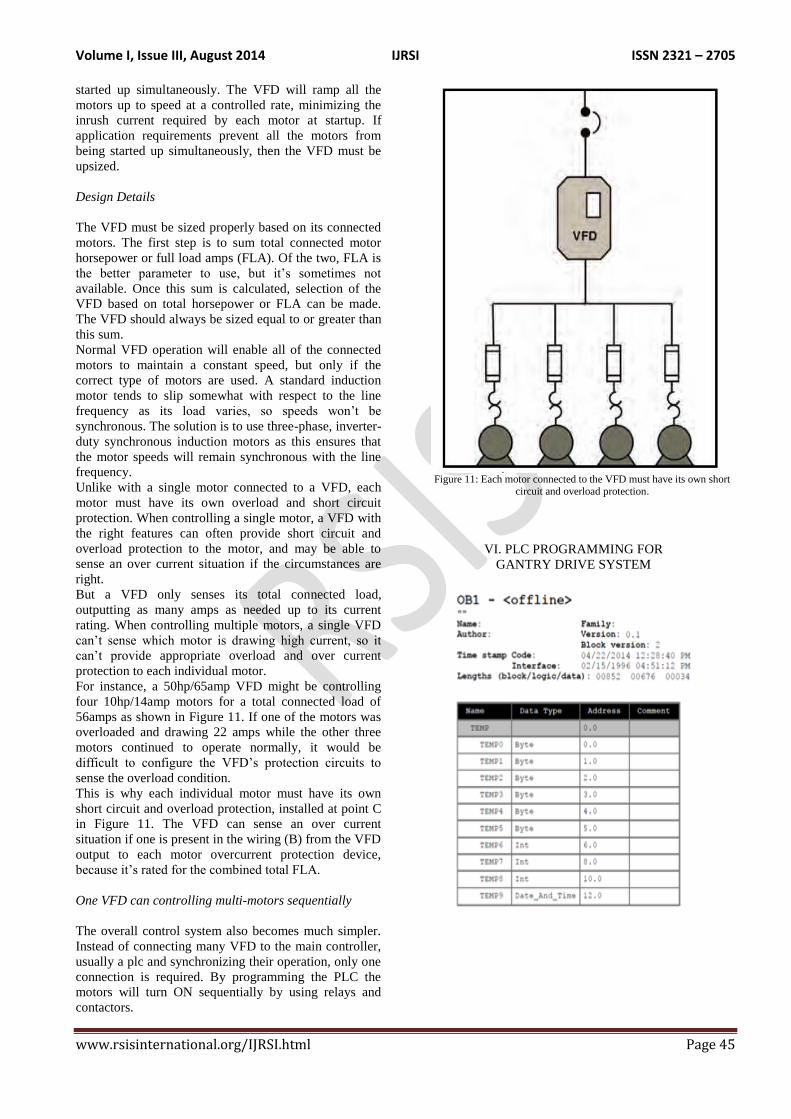
For instance, a 50hp/65amp VFD might be controlling
four 10hp/14amp motors for a total connected load of
56amps as shown in Figure 11. If one of the motors was
overloaded and drawing 22 amps while the other three
motors continued to operate normally, it would be
difficult to configure the VFD‟s protection circuits to
sense the overload condition.
This is why each individual motor must have its own
short circuit and overload protection, installed at point C
in Figure 11. The VFD can sense an over current
situation if one is present in the wiring (B) from the VFD
output to each motor overcurrent protection device,
because it‟s rated for the combined total FLA.
One VFD can controlling multi-motors sequentially
The overall control system also becomes much simpler.
Instead of connecting many VFD to the main controller,
usually a plc and synchronizing their operation, only one
connection is required. By programming the PLC the
motors will turn ON sequentially by using relays and
contactors.
Figure 11: Each motor connected to the VFD must have its own short
circuit and overload protection.
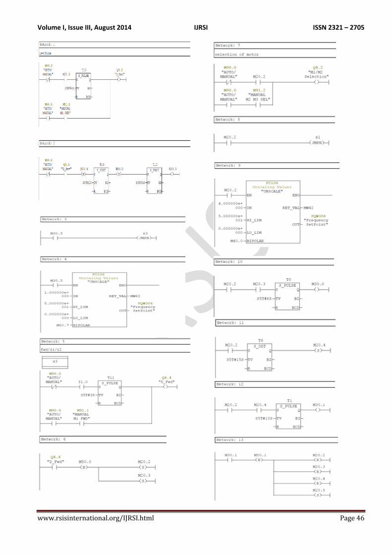
VI. PLC PROGRAMMING FOR
GANTRY DRIVE SYSTEM
Volume I, Issue III, August 2014 IJRSI ISSN 2321 – 2705
www.rsisinternational.org/IJRSI.html Page 46
Volume I, Issue III, August 2014 IJRSI ISSN 2321 – 2705
www.rsisinternational.org/IJRSI.html Page 47
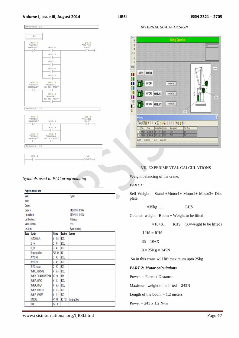
Symbols used in PLC programming
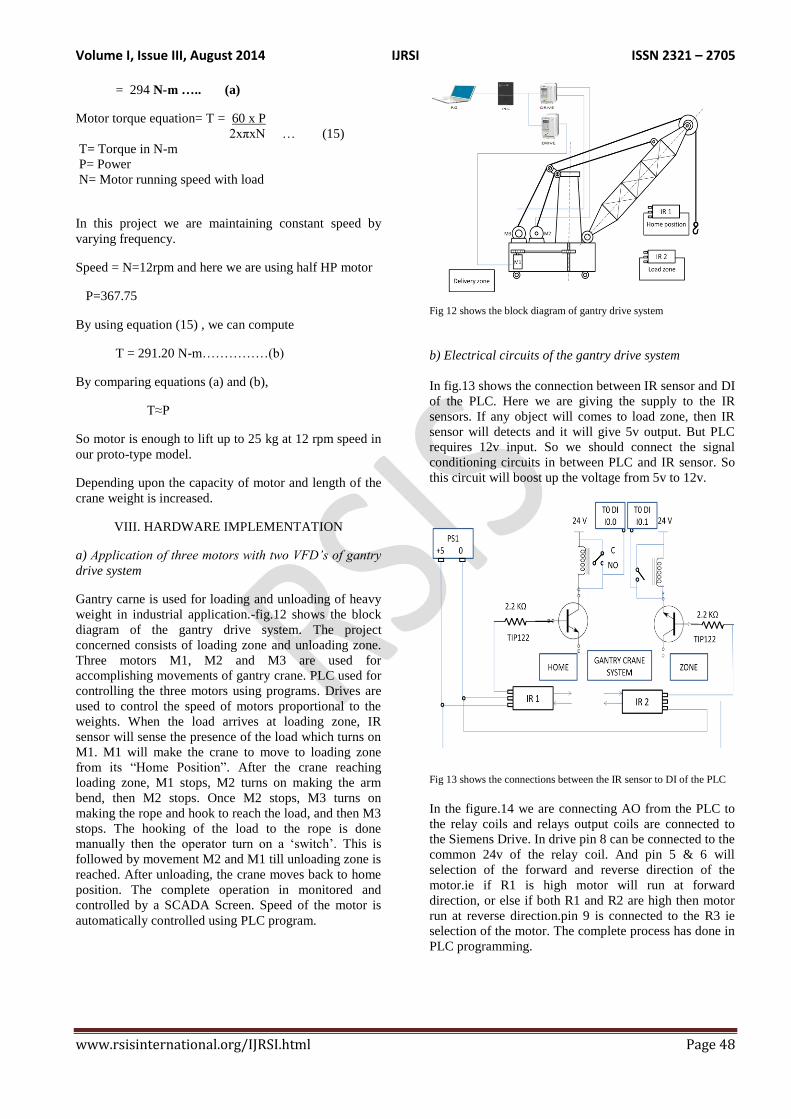
INTERNAL SCADA DESIGN
VII. EXPERIMENTAL CALCULATIONS
Weight balancing of the crane:
PART 1:
Self Weight = Stand +Motor1+ Motor2+ Motor3+ Disc
plate
=35kg ..... LHS
Counter weight =Boom + Weight to be lifted
=10+X.. RHS (X=weight to be lifted)
LHS = RHS
35 = 10+X
X= 25Kg = 245N
So in this crane will lift maximum upto 25kg
PART 2: Motor calculations
Power = Force x Distance
Maximum weight to be lifted = 245N
Length of the boom = 1.2 meters
Power = 245 x 1.2 N-m
Volume I, Issue III, August 2014 IJRSI ISSN 2321 – 2705
www.rsisinternational.org/IJRSI.html Page 48
= 294 N-m ….. (a)
Motor torque equation= T = 60 x P
2xπxN … (15)
T= Torque in N-m
P= Power
N= Motor running speed with load
In this project we are maintaining constant speed by
varying frequency.
Speed = N=12rpm and here we are using half HP motor
P=367.75
By using equation (15) , we can compute
T = 291.20 N-m……………(b)
By comparing equations (a) and (b),
T≈P
So motor is enough to lift up to 25 kg at 12 rpm speed in
our proto-type model.
Depending upon the capacity of motor and length of the
crane weight is increased.
VIII. HARDWARE IMPLEMENTATION
a) Application of three motors with two VFD’s of gantry
drive system
Gantry carne is used for loading and unloading of heavy
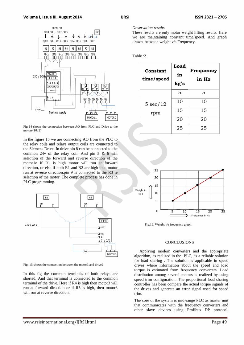
weight in industrial application.-fig.12 shows the block
diagram of the gantry drive system. The project
concerned consists of loading zone and unloading zone.
Three motors M1, M2 and M3 are used for
accomplishing movements of gantry crane. PLC used for
controlling the three motors using programs. Drives are
used to control the speed of motors proportional to the
weights. When the load arrives at loading zone, IR
sensor will sense the presence of the load which turns on
M1. M1 will make the crane to move to loading zone
from its “Home Position”. After the crane reaching
loading zone, M1 stops, M2 turns on making the arm
bend, then M2 stops. Once M2 stops, M3 turns on
making the rope and hook to reach the load, and then M3
stops. The hooking of the load to the rope is done
manually then the operator turn on a „switch‟. This is
followed by movement M2 and M1 till unloading zone is
reached. After unloading, the crane moves back to home
position. The complete operation in monitored and
controlled by a SCADA Screen. Speed of the motor is
automatically controlled using PLC program.
Fig 12 shows the block diagram of gantry drive system
b) Electrical circuits of the gantry drive system
In fig.13 shows the connection between IR sensor and DI
of the PLC. Here we are giving the supply to the IR
sensors. If any object will comes to load zone, then IR
sensor will detects and it will give 5v output. But PLC
requires 12v input. So we should connect the signal
conditioning circuits in between PLC and IR sensor. So
this circuit will boost up the voltage from 5v to 12v.
Fig 13 shows the connections between the IR sensor to DI of the PLC
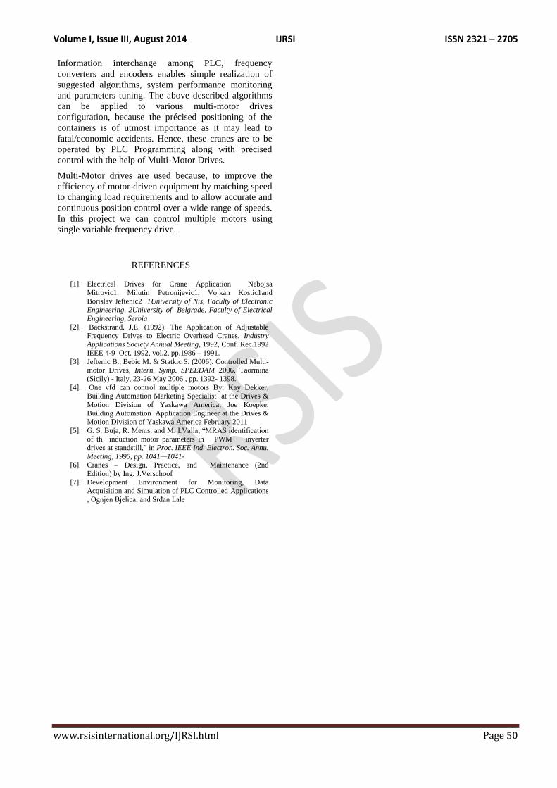
In the figure.14 we are connecting AO from the PLC to
the relay coils and relays output coils are connected to
the Siemens Drive. In drive pin 8 can be connected to the
common 24v of the relay coil. And pin 5 & 6 will
selection of the forward and reverse direction of the
motor.ie if R1 is high motor will run at forward
direction, or else if both R1 and R2 are high then motor
run at reverse direction.pin 9 is connected to the R3 ie
selection of the motor. The complete process has done in
PLC programming.
Volume I, Issue III, August 2014 IJRSI ISSN 2321 – 2705
www.rsisinternational.org/IJRSI.html Page 49
Fig 14 shows the connection between AO from PLC and Drive to the
motors(1& 2)
In the figure 15 we are connecting AO from the PLC to
the relay coils and relays output coils are connected to
the Siemens Drive. In drive pin 8 can be connected to the
common 24v of the relay coil. And pin 5 & 6 will
selection of the forward and reverse direction of the
motor.ie if R1 is high motor will run at forward
direction, or else if both R1 and R2 are high then motor
run at reverse direction.pin 9 is connected to the R3 ie
selection of the motor. The complete process has done in
PLC programming.
Fig. 15 shows the connection between the motor3 and drive2
In this fig the common terminals of both relays are
shorted. And that terminal is connected to the common
terminal of the drive. Here if R4 is high then motor3 will
run at forward direction or if R5 is high, then motor3
will run at reverse direction.
Observation results
These results are only motor weight lifting results. Here
we are maintaining constant time/speed. And graph
drawn between weight v/s Frequency.
Table :2
Constant
time/speed
Load
in
kg’s
Frequency
in Hz
5 sec/12
rpm
5 5
10 10
15 15
20 20
25 25
Fig.16. Weight v/s frequency graph
CONCLUSIONS
Applying modern converters and the appropriate
algorithm, as realized in the PLC, as a reliable solution
for load sharing . The solution is applicable in speed
drives where information about the speed and load
torque is estimated from frequency converters. Load
distribution among several motors is realized by using
speed trim configuration. The proportional load sharing
controller has been compare the actual torque signals of
the drives and generate an error signal used for speed
trim.
The core of the system is mid-range PLC as master unit
that communicates with the frequency converters and
other slave devices using Profibus DP protocol.
Volume I, Issue III, August 2014 IJRSI ISSN 2321 – 2705
www.rsisinternational.org/IJRSI.html Page 50
Information interchange among PLC, frequency
converters and encoders enables simple realization of
suggested algorithms, system performance monitoring
and parameters tuning. The above described algorithms
can be applied to various multi-motor drives
configuration, because the précised positioning of the
containers is of utmost importance as it may lead to
fatal/economic accidents. Hence, these cranes are to be
operated by PLC Programming along with précised
control with the help of Multi-Motor Drives.
Multi-Motor drives are used because, to improve the
efficiency of motor-driven equipment by matching speed
to changing load requirements and to allow accurate and
continuous position control over a wide range of speeds.
In this project we can control multiple motors using
single variable frequency drive.
REFERENCES
[1]. Electrical Drives for Crane Application Nebojsa Mitrovic1, Milutin Petronijevic1, Vojkan Kostic1and
Borislav Jeftenic2 1University of Nis, Faculty of Electronic
Engineering, 2University of Belgrade, Faculty of Electrical Engineering, Serbia
[2]. Backstrand, J.E. (1992). The Application of Adjustable
Frequency Drives to Electric Overhead Cranes, Industry Applications Society Annual Meeting, 1992, Conf. Rec.1992
IEEE 4-9 Oct. 1992, vol.2, pp.1986 – 1991.
[3]. Jeftenic B., Bebic M. & Statkic S. (2006). Controlled Multi-motor Drives, Intern. Symp. SPEEDAM 2006, Taormina
(Sicily) - Italy, 23-26 May 2006 , pp. 1392- 1398.
[4]. One vfd can control multiple motors By: Kay Dekker, Building Automation Marketing Specialist at the Drives &
Motion Division of Yaskawa America; Joe Koepke,
Building Automation Application Engineer at the Drives & Motion Division of Yaskawa America February 2011
[5]. G. S. Buja, R. Menis, and M. I.Valla, “MRAS identification
of th induction motor parameters in PWM inverter drives at standstill,” in Proc. IEEE Ind. Electron. Soc. Annu.
Meeting, 1995, pp. 1041—1041-
[6]. Cranes – Design, Practice, and Maintenance (2nd Edition) by Ing. J.Verschoof
[7]. Development Environment for Monitoring, Data Acquisition and Simulation of PLC Controlled Applications
, Ognjen Bjelica, and Srđan Lale