design and implementation project wide band · esd-tr-81-135 v" jmtr-8174 design and...
TRANSCRIPT

ESD-TR-81-135 V" JMTR-8174
DESIGN AND IMPLEMENTATIONOF
PROJECT 7140 WIDE BAND HF COMMUNICATION TEST FACILITY
B.D. PERRY
July 1981
Prepared for
DEPUTY FOR COMMAND AND CONTROL DIVISIONLONG WAVE COIVMUNICATION SECTION
ELECTRONIC SYSTEMS DIVISIONAIR FORCE SYSTEMS COMMAND TIC
UNITED STATES AIR FORCEHanscom Air Force Base, Massachusetts D" )
JUL S
Project No. 7140
Approved for public rless; Prepared by
distribution unlimited. THE MITRE CORPORATION
Bedford, Massachusetts
Contract No. F19628-80-C-0001
81 7 31 099

When U.S. Government drawinga, spaclfications, or other data are used for any
purpose other than a definitely related government procurement operation, the
government thereby incurs no responsibility nor any obligation whatsoever; and
the fact that the government may have formulated, furnished, or in any way
supplied the said drawings, specifications, or other data is not to be regarded by
implication or otherwise, as in any manner licensing the holder or any other
person or corporation, or conveying any rights or permission to manufacture,
use, or sell any patented invention that may in any way be related thereto.
Do not return this copy. Retain or destroy.
REVIEW AND APPROVAL
This technical report has been reviewed and is approved for publication.
• GAMBLE/GS- 14
Project Engineer
FOR THE COMMANDER
Deputy to Command and Lontrol DivisionLong Wave Communication Section
-i

UNCILASSIrmn~fSECURITY ;ASSIFICATION OF THIS PAGE (When~u Date Entered) __________________
REPOT DCUMNTATON AGEREAD INSTRUCTIONSREPOT DCUMNTATON AGEBEFORE COMPLETING FORM
2. GOV ACCESSION NO. 3. RECIPIENT'S CATALOG NUMBER
ESD TR-81-135 1h h 1 -1 1TI TL E (en -ubtWtl) S. TYPE OF REPORT & PERIOD COVERED
aESIGN ANDWPLEMENTATION OF&ROJECT'74 UEA- FCMMUNICATIOI TEST____ _______
FACIUTY . PELRFORMNG 0ORG. REPORT NUMBER
/)A MTR-8174 I/L_O-4C NGI~Th~~BRa
.B .PERRY _ ______C-##
39-WERFORMING ORGANIZATION NAME AND AORESS 10. PROGRAM ELEMENT. PROJECT, TASKThe MTRE orportionAREA A WORK UN IT NUMBERS
P. 0. Box 208 7140Bedford, MA 01730
It. CONTROLLING OFFICE NAME AND ADDRESS EPO*T-OA-a
Deputy for Command and Control Division, Long Jue-~ai 14)Wave Communication Section, Electronic SystemsDiv., AFSC , Hanscom AFB, MA 01731 97
14. NITORING AGENCY NAME & ADDRESS(if different from Controlling Office) 1S. SECURITY CLASS. (of this report)
!97?~j~k~,/'Ji LP~+UNCLASSIFIED5sa. DECL ASSI FICATION/ DOWNGRADING
SCHEDULE
16. DISTRIBUTION STATEMENT 'of this Report)
Approved for public release distribution unlimited
17. DISTRIBUTION STATEMENT (of the ebstract entered In Block 20, If different from Report)
IS. SUPPLEMENTARY NOTES
19. KEY WORDS (Continue on reverse aide it necessary end Identify by block number)
ADAPTIVE EQUALIZATIONIONOSPHERIC COMMUNICATIONS
WIDE BAND HF COMMUNICATION
20. 6BSTRACT (Continue on reverse side if neceaeery end Identify by block number)
>The primary objective of project 7140 is to prove the feasibility of the concept ofHF communications -- using signals having bandwidths on the order of one megahertzthrough a series of experiments employing a flexible test facility designed and builtfor this purpose The test facility inc udes a transmitter, equalized receiver, and
interference measurement and other support equipments This report concentrates
(over)FOR
DD JA 7 1473 UNCLASSIFIED 4SECURITY CLASSIFICATION OF THIS PAGE (UWen Does Eneed)

TTNr. .ARqT rT.nSECURITY CLASSIPICATION OF TWIS PA@(IShm Data Effiered
20 ABSTRACT (Concluded)
on the design and realization of the test facility. Descriptions of the wideband HFchannel and the planned experimental program are also included.
UNCLASSIFIED
SECURITY CLASSIFICATION OF THIS PAGE(Whn Date Entored)

ACKNOWLEDGMENTS
This report has been prepared by The MITRE Corporation under
Project No. 7140. The contract is sponsored by the Electronic Systems
Division, Air Force Systems Command, Hanscom Air Force Base, Massachusetts.
The author wishes to acknowledge the many contributions of others to
the design and implementation of the test facility. In particular he
wishes to thank D. R. Bungard, H. E. T. Connell, B. L. Johnson, L. Lau,
C. E. Pearson, J. R. Reisert, G. B. Tiffany, and S. S. Weinrich.
Accession For
NTIS GRA&IDTIC TABUnannounced
Justification
By
Distributi on/
Availability Codes
Avnil and/orDist Special
i

ABSTRACT
The primary objective of project 7140 is to prove the feasibility
of the concept of HF communications - using signals having bandwidths
on the order of one megahertz - through a series of experiments em-
ploying a flexible test facility designed and built for this purpose.
The test facility includes a transmitter, equalized receiver, and in-
terference measurement and other support equipments. This report
concentrates on the design and realization of the test facility.
Descriptions of the wideband HF channel and the planned experimental
program are also included.
iv

TABLE OF CONTENTS
Section Page
LIST OF ILLUSTRATIONS
LIST OF TABLES
I. INTRODUCUTION 1
1.1 Summary 1
1.2 Purpose 2
1.3 Background 2
1.4 outline 3
II. WIDEBAND HF CHANNEL CHARACTERISTICS 5
2.1 lonograms 5
2.2 Transfer Functions 7
2.2.1 Full HF Band 8
2.2.2 Band-limited 8
2.3 Measured Parameters 10
2.4 Noise and Interference 12
III. DESIGN APPROACH 13
3.1 Selection of Equalizer Parameters 13
3.2 Measurement of Channel Transfer Function 16
3.2.1 Probe Signal Acquisition 19
3.3 Computation of Equalizer Coefficients 24(for Inverse Filtering)
3.3.1 Fast Convolution 27
v

7r
TABLE OF CONTENTS (CONTINUED)
Section Page
3.4 Transversal Filter Equalizer 29
3.5 Spread Spectrum Test Signals 32
3.5.1 FFH Waveform 32
3.6 Spectrum Analysis of Interference 35
3.6.1 Analyzer Resolution 35
IV. TEST FACILITY DESCRIPTION 39
4.1 Equalizer 39
4.1.1 Equalizer Interface Unit 44
4.1.2 Equalizer Detailed Description 44
4.1.3 High-Speed Digital Multiplier 49
Problem
4.1.4 Equalizer Testing 49
4.2 Coefficient Computer 51
4.2.1 Coefficient Computer Software 51
4.2.2 Coefficient Computer Hardware 54
4.3 Time/Frequency Circuits 54
4.3.1 Frequency Standards 54
4.3.2 Clock Generation 56
4.3.3 System Timing Generator 56
4.3.4 Program Generation 59
4.3.5 Frequency Synthesizers 61
4.4 Transmitter and Receiver Analog Ciicuits 61
4.4.1 Exciter and Receiver Front End 63
vi

TABLE OF CONTENTS(CONTINUED)
Section Page
4.4.2 Transmitter Amplifier Chain 65
4.4.3 Antennas 65
4.4.4 Receiver Back End and Display 69
4.5 Spectrum Analysis Equipment 71
4.6 Peripheral Equipment 71
4.6.1 WWV/CHU Reception and Synchronization 71
4.6.2 SSB Voice Communications 74
4.6.3 Wideband Recording Facility 74
4.7 PN Spread Spectrum Capability 77
V. EXPERIMENTAL PROGRAM 79
5.1 Data Taking 79
5.2 Data Analysis 80
REFERENCES 83
vii

rw
LIST OF ILLUSTRATIONS
Figure Page
1 OBLIQUE IONOGRAM 6
2 SKETCH OF TRANSFER FUNCTION [C(w) = E(w)eJD(w)] 9FOR FULL HF BAND
3 TYPICAL BAND-LIMITED TRANSFER FUNCTION FOR SINGLE- 11
MODE OBLIQUE PROPAGATION
4 PROBE SIGNAL SPECTRUM; NO TIME TRUNCATION 17
5 PROBE SIGNAL SPECTRUM; ONE SECOND TIME TRUNCATION 17
6 PROBE SIGNAL: TIME-MULTIPLEXED TRANSMISSION 18
7 PROBE SIGNAL; LFM CODING ON EACH SEGMENT, NO 20
SCRAMBLING
8 PROBE ACQUISITION CIRCUITRY 21
9 PROBE SAMPLING FOR CHANNEL TRANSFER FUNCTION 23
MEASUREMENT
10 INVERSE FILTER EQUALIZATION 25
11 EQUALIZER AS A BANK OF FILTERS 26
12 EQUALIZATION IN THE FREQUENCY DOMAIN VIA FAST 28CONVOLUTION
13 TAPPED DELAY LINE, TRANSVERSAL FILTER, DE-CONVOLVING 30EQUALIZER
14 FFH WAVEFORM 34
15 PANORAMIC SPECTRUM ANALYSIS 36
16 ONE-WAY WIDEBAND HF COMMUNICATIONS TEST FACILITY 40
17 MOBILE TRANSMIT TERMINAL 41
18 TRANSMIT TERMINAL EQUIPMENT 42
ix

LIST OF ILLUSTRATIONS(CONTINUED)
Fig!re Page
19 RECEIVE TERMINAL EQUIPMENT 43
20 EQUALIZER INTERFACE UNIT 45
21 PROGRAMMABLE EQUALIZER 46
22 EQUALIZER DETAILS (SHADED REGION OF FIGURE 21) 48
23 EQUALIZER TEST RESULTS 50
24 COEFFICIENT COMPUTER INTERFACES 52
25 COEFFICIENT COMPUTER FUNCTIONAL DESCRIPTION 53
26 TIME/FREQUENCY CIRCUITS 55
27 CLOCK GENERATION CIRCUITS 57
28 TIMING GENERATOR 58
29 SYNTHESIZER PROGRAM GENERATION LOGIC 60
30 EXCITER AND RECEIVER FRONT-END 64
31 EXCITER OUTPUT SPECTRUM 66
32 TRANSMITTER AMPLIFIER CHAIN 67
33 TRANSMITTER OUTPUT SPECTRUM 68
34 RECEIVER BACK-END AND DISPLAY 70
35 RECEIVE TERMINAL INTERFERENCE SPECTRUM ANALYSIS 72EQUIPMENT
36 TRANSMIT TERMINAL RECONFIGURED FOR INTERFERENCE 73ANALYSIS
37 WWVICHU RECEPTION AND SYNCHRONIZATION 75
38 WIDEBAND RECORDING FACILITY 76
x

LIST OF TABLES
Table Page
1 SYNTHESIZER FREQUENCY CONTROL PROGRAMS 62
xi

SECTION I
INTRODUCTION
In this section the report is summarized and its purpose and
background are discussed.
1.1 Summary
In the late 1960's, an Air Force ionospheric measurement pro-gram conducted by MITRE proved that signals whose bandwidths were
ten percent or more of the carrier frequency could be transmitted
via HF sky-wave paths provided an appropriate wideband channel equal-
izer could be realized. ( 1 2 )' In this current program, such a pro-
grammable transveral filter equalizer has been built and installed
in a one-way wideband HF sky-wave communication test facility. The
equalizer's key parameters are a bandwidth (W) of 1024 kHz, an
impulse response duration (T) of 125 ps, and a dynamic range of about
50 dB. These parameters are commensurate with reasonable extra-
polations of the data taken during the earlier program. The weighting
coefficients required to program the equalizer as an inverse filter
are derived from probe signal measurements of the transfer function
of the ionospheric path. Two phase-coherent, programmable frequency
synthesizers are used for probe and fast-frequency-hop spread spec-
trum signal generation and demodulation. The test facility includes
antennas, a wideband transmitter and receiver for the 4-to 30-MHz
HF band, and the necessary supporting and peripheral circuitry and
equipments. In addition, both terminals of the test facility can be
configured for simultaneous interference spectral analysis within
the wide bandwidth.
4.A fljfl

The test facility will be used in a proof-of-concept demonstra-
tion of wideband HF communications and for establishing a data base
which can be used for future wideband HF modem designs. Data taking
and data analysis will emphasize topics such as anti-jamming (AJ),
low-probability-of-intercept (LPI) communication, and the effects of
interference.
Wideband HF will provide an alternative to satellite and tropo-
spheric-scatter communications and will permit the use of spread spec-
trum communications with the attendant features of AJ protection
and/or LPI communications. In addition, the multipath modes can
often be resolved, thereby reducing fading and permitting the option
of either increasing the circuit reliability or reducing the trans-
mitted power level.
1.2 Purpose
The purpose of this report is to describe the design and imple-
mentation of a wideband HF communications test facility under Project
7140: "Wideband HF Technology." This test facility is capable of
measuring the characteristics of a wideband HF channel, transmitting
spread spectrum signals one-way over that channel, and measuring the
noise and interference present at both the transmit and receive ter-
minals of the channel.
1.3 Background
Communications links in the 3- to 30-MHz hIF band are important
to many classes of users, both civilian and military. Civilian
applications include international "shortwave" broadcasting services,
radio telegraphy, ship-to-shore communications, and transoceanic air
traffic control. All three military services have relied and con-
tinue to rely on HF links for both short-haul tactical communications
2

and longer-distance strategic links. The principal advantage of
HF sky-wave communications is its relatively low cost for beyond-
line-of-sight applications. Its many disadvantages, however, include
limited channel bandwidths and various degradations caused by the
vagaries of the ionosphere (and earth reflections for multi-hop
links).
The earlier MITRE work (1'2 ) involved the measurement of the
characteristics of oblique HF paths over bandwidths of up to 4.5 MHz.
This work led to the discovery that the path parameters varied quite
slowly and to the consequent conclusion that path equalization would
be feasible once the requisite technology became available. With the
advent of large-scale and very-large-scale-integrated (LSI and VLSI)
signal processing devices path equalizers for bandwidths of 1 MHz or
greater can now be realized.
Project 7140 began on 1 October 1978. During the first year,
alternative equalizer design approaches were considered, one was
chosen. a flexible test facility including the chosen equalizer was
designed, and implementation bagan. During this the second year,
the implementation has been completed. In the process of completion
certain portions of the test facility were redesigned to overcome
inadequacies in the original design and make use of resources not
previously available.
1.4 Outline
In section II the characteristics of wideband HF channels are
summarized. These characteristics are then used as a basis for the
3

test facility design approach described in section III and test
facility implementation described in section IV. The planned exper-
imental program using the test facility is described in section V.
4

SECTION II
WIDEBAND HF CHANNEL CHARACTERISTICS
In this section the existing information on wideband HF propa-
gation channel characteristics is summarized to provide a reference
for the design approach described in section III.
2.1 lonograms
The most common technique for measuring the characteristics of
the ionospheric propagation paths that exist between two points
(i.e. the terminals of a radio communications circuit) is to use
oblique ionospheric sounding equipment and generate "oblique iono-
grams. An ionogram is an intensity-modulated display of the time
of arrival of the transmitted pulse (or its equivalent as in the case
of a "chirp sounder") as a function of frequency across the entire
HF band. A typical ionogram is shown in Figure 1. It exhibits one-,
two-, and three-hop modes. The primary mode of propagation is the
lowest, or one-hop, mode. As can he seen, it is dispersive, with its
time of arrival varying from 1.0 ms at 16 MHz to approximately 1.2 ms
at the "nose" of the trace (commonly referred to as the maximum
usuable frequency or MUF) at 22.5 MHz. Between 20 MHz and the MUF,
the upper ray (sometimes called the Pederson ray) is visible. Thus
there remains a "window" between about 15 and 20 MHz where only a
single mode propagates and where intermode multipath fading will not
occur.
There are two other features of importance displayed in this
Jonogram. The vertical traces are caused by the strongest of the
many narrowband emitters which were interfering with the reception
of the sounding signal. This interference is usually most predomi-
nant in the international AM broadcast bands. The somewhat periodic
a5

C,41
CL CN
CL0
LL
NN 4
00L ww
0 0 aCLIL
0 0
LLL
-I 0 0
(oeswL) 1VAIHHV-AO-3AIl 3AIIV1HU
6

intensity modulation, which is especially apparent on the one-hop
trace, is due to the Faraday rotation effect. The transmitted
linearly polarized wave is constituted of two components - a left-
hand circular component and a right-hand circular component. These
components are affected differently by the earth's magnetic field.
Consequently, they arrive at the receiver with a small difference
in time of arrival. (Typically the difference is a few microseconds
on oblique paths.) This effect leads to a slow fading rate at any
particular frequency as the received wave rotates in polarization
with respect to the receiving antenna polarization. In addition
this effect leads to a frequency-dependent interference pattern
which, as can be seen, exhibits minima about every few hundred kHz.*
2.2 Transfer Functions
Another way of describing the sky-wave propagation between two
points is by assuming it can be modeled by a linear time-invariant
network and its associated transfer function. The assumption of
linearity is generally valid, except for the rarely observed Luxemburg
effect**. The assumption of time invariance is justified for wide-
band HF propagation by the earlier MITRE work ( 1,2 ) which showed
time invariance to typically be 10 seconds (but up to at least 30
seconds during the daytime and as little as one second during dawn-
dusk transitions).
*For a more complete description of Faraday rotation and its effecton oblique path characteristics, see reference 3.
**This effect is ionospheric cross-modulation between two trans-missions on different carrier frequencies. It is only observedwhen high-power transmitters are involved such as the venerableRadio Luxemburg.

2.2.1 Full HF Band
We define the transfer function as C(w) f E(w)ej D(w) and show
in Figure 2 a simplified sketch of the magnitude E(w) and the nega-
tive phase derivative or group delay T (w) as a function of frequency
that one would expect for the path associated with the ionogram of
Figure 1. (Group delay is shown rather than phase because it is
more closely related to the ionogram.) For those frequencies where
more than one propagation mode exists (i.e., one-hop plus two-hop or
upper plus lower ray) the magnitude term varies periodically with
maxima spaced by the reciprocal of the delay difference between the
modes. In addition Faraday rotation causes a fluctuation in the
magnitude term, as described in section 2.1 above, for each mode.
This fluctuation is not generally observable for multi-hop modes,
however, because the differential delay associated with this effect
is less than the smearing in time of arrival due to the nonspecular
earth reflection(s).
2.2.2 Band-limited
The typical wideband channel will be on the order of one mega-
hertz in extent (see sections 2.3 and 3.1). In many cases it will
be possible to select a one-megahertz band where only the one-hop
mode propagates and where the upper ray is at least 20 dB down with
respect to the lower ray. (In Figures 1 and 2 this would be the
region between 15 and about 21.5 MHz.) This simplifies the channel
equalizer and leads to the design incorporated in the test facility
which is the subject of this report. In those cases where signifi-
cant energy propagates by more than one (widely separated) mode
(within the band chosen), this simplified equalizer is still useful
for spread spectrum communications as will be described in 3.1.
8

x
I0 0N N rz
U LU2n a U.1
La Ln
m a) 3anmovw Fix)a o =U"?.L)Av-ioadnome

2.3 Measured Parameters
(1,2)The earlier MITRE program provided a somewhat limited but
nevertheless useful data base with respect to the characteristics of
wideband HF channels. The data base was limited to one-hop cases as
described in the previous section and was confined to the temperate
latitudes where auroral effects are not present. The data base is
particularly useful in that from it we can confidently extrapolate
to a set of equalizer parameters for the design incorporated in this
test facility. Figure 3 is a sketch of the typical band-limited
transfer function represented by this data base. The bandwidth (W)
is that of (1) the signal transmitted to measure or "probe" the
channel transfer function and (2) the inverse-filter equalizer used
to compensate for the channel. Within this band, AE is the peak-to-
peak magnitude variation, AT is the maximum group delay differenceg
or the "dispersion," and At is the average delay difference between
the so-called "ordinary" and "extraordinary" ray components due to
the magneto-ionic splitting (i.e. Faraday rotation).
It should be noted that AT in a given band W (say one megahertz)g
increases as the path length is reduced and as the carrier frequency
(f ) is also reduced so as to stay below the MUF. To minimize this
dependence of AT on f the restriction that W:0.1f is applied.g o o
We can then summarize the one-hop data base of the earlier MITRE
work as follows:*
For W0O.1f0
* AE is observed to be "less than 30 dB most of the time".
* ATg is observed to be "a few tens of microseconds most ofthe time,'" but over 100 us at or near dawn and dusk.
0 At is observed to be in the order of "a few microseconds".
*For very short paths where the propagation can not be characterizedas oblique, AT is somewhat larger and the data as summarized heredoes not necessarily apply. 10

LL toCr
00
LU.
I-I
0
1 '-4
EIL'-
(E-4
00II4
ItI

These observed parameters were typically time invariant over 10
seconds.
2.4 Noise and Interference
The terms noise and interference have somewhat unique connota-
tions in the HF band. The predominant noise is external to the re-
ceiver and is due to both man-made (ignitions, power lines, machinery,
etc.) and natural (thunderstorms, galactic sources) causes. This
external noise is best distinguished from interference in that it is
broadband. The noise bandwidths involved do not always encompass the
entire HF band but are at least greater than the bandwidths consider-
ed under "wideband HF communications." The methods used to calculate
and otherwise deal with noise are therefore no different that those
used in more traditional narrowband HF communications.
HF band interference is narrowband, however, since it consists
of the emissions from various transmitters operating in their assigned
narrowband channels. The methods used to deal with interference in
the wideband HF case are different from those used in the traditional
narrowband situations. The narrowband user attempts to avoid the
interference by selecting a quiet channel. The wideband user can
neqer expect to totally avoid the interference (although he can
certainly attempt to avoid the more crowded frequency bands, at least
in the daytime). The wideband user can, however, gain an advantage
over the interference through signal processing in that the wideband
receiver will be mismatched to the typical narrowband waveform. In
addition, the wideband user might choose to (1) modify the trans-
mitted signal so as to avoid transmitting in time and/or frequency
slots which are occupied by others or (2) use noise whitening signal
processing techniques in the receiver.
12

SECTION III
DESIGN APPROACH
In this section the approach taken to the design of the test
facility is discussed. This approach is to:
1) design a wideband equalizer which will compensate for thechannel in the receiver by operating as a programmablefilter whose transfer function is the inverse of that ofthe channel,
2) provide a means of measuring the channel transfer function
and from it calculate the equalizer filter coefficients,
3) transmit wideband "spread-spectrum-like" signals over theequalized channel, and
4) provide a means of measuring the characteristics of theinterference within the wideband channel.
Thus the facility can be used to expand the data base of the earlier
MITRE work, prove the concept of wideband HF communications, and
determine what can and/or should be done to mitigate the effects of
interference. In essence the facility will measure and deal with
the vagaries of the channel transfer function and measure but not
directly deal with the effects of interference.
3.1 Selection of Equalizer Parameters
The need for a channel equalizer arises when one attempts to use
a bandwidth greater than the correlation bandwidth of the ionosphere.
For multi-mode situations, this bandwidth is as low as 0.3 kHz. For
single, one-hop mode situations, this bandwidth is on the order of
50 to 100 kHz.* These facts together with our previous experience( 1'2 )
*This value is an average over time of day and geography. Lower
values are to be expected at dawn/dusk and in auroral regions. Con-versely, values as large as several hundred kHz have been observedin temperate latitude, daytime situations.
13

indicated that an equalizer bandwidth on the order of one megahertz
or ten percent of the carrier frequency (whichever is smaller) would
be appropriate and could be realized using present-day circuit tech-
nology. For design convenience W = 1024 kHz has been selected with
an option to use one half the bandwidth (512 kHz).
Channel equalization using inverse filtering is not the optimum
strategy in all circumstances. For example, conjugate filtering,
wherein the adaptive receiver is configured as a matched filter to
the convolution of the transmitted waveform and the channel impulse
response, is a better strategy for low signal-to-noise applications.
However, high signal-to-noise ratios are the rule in HF communications
(except where strong interference predominates or where either
absorption or multipath cause the signal to suffer a deep fade ex-
ceeding the transmitter power reserve designed for this contingency).
We therefore provide sufficient transmitter power, expect a high re-
ceiver signal-to-noise ratio, and use an inverse filter equalizer.
Other equalization strategies can be implemented by using a
method of calculating equalizer coefficients that is different from
the method described in section 3.3. Later in the program, the test
facility may be modified to accommodate one or more of these strat-
egies.
The second important equalizer parameter is the duration of its
impulse response (T). In order to correct for dispersion, it is only
necessary that T be equal to or greater than AT . To correct forg
multipath, however, T must exceed AT by about an order of magnitude.
Even then it will be insufficient in the pathological case wherein:
1) the two multipath signals are exactly equal in magnitude,
2) there consequently are zeros in the channel transferfunction, and thus
3) the required T goes to infinity.
14

The equalizer is realized as a finite-impulse-response filter
and the value of T chosen is 125 us. This value satisfies both the
requirements of T ATg and T >> AT, at least in the vast majority
of expected situations.
The third important parameter is dynamic range. In section 2.3
it is indicated that 30 dB will be sufficient. The chosen value is
about 51 dB which allows a more than 20-dB worst-case margin in the
presence of strong in-band interferring signals. It is achieved by
8-bit rectangular coordinate processing.Although the selection of this W = 1024 kHz and T = 125 ps (and
8-bit processing) drive the equalizer design realization and describe
its capability, the equalizer can also be reconfigured for three
other arrangements. The following are the four alternatives:
1. W = 1024 kHz, T = 125 ps. (128 samples 8 kHz apart infrequency and 0.977-ps tap spacing.)
2. W = 1024 kHz, T = 62.5 us. (64 samples 16 kHz apart infrequency and 0.977-ps tap spacing.)
3. W = 512 kHz, T = 125 ps. (64 samples 8 kHz apart infrequency and 1.95-ps tap spacing.)
4. W = 512 kHz, T = 250 Ps. (128 samples 4 kHz apart infrequency and 1.95-ps tap spacing.)
These alternatives permit measurements of relative effective-
ness. For example, during disturbed ionospheric conditions the
fourth alternative would possibly be the best choice, whereas, for
very short paths which require low carrier frequencies, the third or
fourth might be best. The second and third alternatives relax the
equalizer design requirements and permit an evaluation of the use-
fulness of simpler equalizer designs than the primary design being
* implemented under this program. (The program also plans to inves-
tigate the effectiveness of the full 8-bit dynamic range capability
Pas compared with lesser capabilities down to 1-bit processing.)
15
... ... .

3.2 Measurement of Channel Transfer Function
Because the channel is band limited to W and its impulse res-
ponse is expected to be no greater than T, 2TW samples in either the
time or frequency domain are sufficient to characterize it. Given
W = 1024 kHz and T = 125 us, 2TW = 256. Rather than impulsing the
channel, we use frequency domain sampling in order to minimize the
peak power radiated for the probe signal and to minimize our inter-
ference to other users. Thus we require 128 complex samples every
I/T = 8 kHz. This can be instrumented, as shown in Figure 4, as the
simultaneous transmission of 128 complex sinusoids 8 kHz apart (1/T
has been defined here as F) from a bank of phase-coherent frequency
sources.
Since the channel is not time invariant, however, we must com-
plete the probe transmission in less than the "correlation time" of
the ionospheric channel. For the one-second probe transmission time
(Tp) used, the probe signal spectrum lines broaden to 1 Hz widths,
as shown in Figure 5.
A simplification is achieved by time multiplexing the probe
frequency-domain samples, providing sufficient power to guarantee a
good receiver signal-to-noise ratio for each sample, and completing
the 128 transmission segments in one second. The width of each spec-
tral line, which is now 128 Hz, is still much less than AF = 8000
Hz. Figure 6 shows both the time and frequency domain representa-
tions of this probe signal.
In order to discriminate against narrowband interference and
achieve mode isolation so that the probe signal can be used to mea-
sure the ionospheric path transfer function for the desired mode
(which for example in Figure 2 is the one-hop mode), each probe seg-
ment is coded with 8 kHz of linear frequency modulation (LFM). With-
out this coding, the typical mode separation of about one millisecond
16

wU0
1' 2 3 N 1 N( 128)2 -. F (8 kHz)
VV( 1024 kHz) FRQNC
Figure 4: PROBE SIGNAL SPECTRUM; NO TIME TRUNCATION
2 3 ~ N-1 N(= 128)
Z i (= 8kHz)c~1
-FREQUENCY
W (=1024 k~z)
Figure 5: PROBE SIGNAL SPECTRUM; ONE SECOND TIME TRUNCATION
17

,I. N 1 2 3127 128 r, 6F = 12e HSTp
-FREQUENCY
W --1024 kHZ
6a: SpectrumLU
6- - Tp 1 128 SEC 7.8125 MSEC
12 VzI
Tp - 1 SECOND
6b: Time Sequence of Probe Signal Segments
Figure 6: PROBE SIGNAL: TIHE-MULTIPLEXED TRANSMISSION
18
....-. ,,, ,,, _ ., .... ;.__ -..... ...,.im~limlll I I I I

is less than the time-domain resolution of the segment of 7.8125 ms.
Figure 7 shows the resulting LFM probe signal. The channelwhose bandwidth (W) is 1024 kHz is swept in the frame time (T p) of
one second. The sweep consists of 128 contiguous segments. The
time resolution of each segment, which is equal to the reciprocal of
the segment's 8-kHz bandwidth or 125 1s,is sufficient to permit mode
separation. In addition there is no need to increase the peak power
as would be the case if uncoded probe segments less than one milli-
second long were used.
3.2.1 Probe Signal Acquisition
In order to permit acquisition of the desired-mode signal, the
time of arrival must be known or determined to within a small frac-
tion of the segment duration by searching over the residual time
uncertainty. This time can be estimated as follows:
" The uncertainty in time of arrival is the sum of the clocktime-of-day errors at the transmit and receive sites plusthe uncertainty in the propagation delay over the pathbeing measured.
* Using HF time stations (such as WWV in Ft. Collins Coloradoor CHU in Ottawa, Canada) to establish time of day, thetotal uncertainty is that associated with three HF pathsand is in the order of two milliseconds.
Figure 8 shows the method used to search this two millisecond
uncertainty. The received LFM probe signal is demodulated by mixing
with an LFM local oscillator (LO). As a result, any time difference
between the two LFM signals is converted into a frequency difference.
The low pass filter (LPF) thus serves as a time window which dis-
criminates against received signals whose time of arrival differs
from the start time of the LO frame by more than one half of the
window. This window's duration is equal to
2 fc Tp (1)
c W
19

uGO
EZN
N I C,-o oNe4
LL
LL
it01
d' 9
LU
CA O
- In
H zH
0
200

IE-4
40-
4w-
-J
00
> I-iLU co
u 0~CL w
214

where fc= LPF bandwidth in Hz,
Tp= probe frame time in seconds,
and W = bandwidth in Hz.
The LPF is however not matched to the probe segment. Instead,
a lower signal-to-noise ratio is accepted during acquisition in order
to reduce the time required to search over the two millisecond un-
certainty interval.
In the test facility, fc = 400 Hz and Tp = 1 second. For W =
1024 kHz, equation (1) yields Tc - 781 vs. Since each trial setting
of start of frame must be held for Tp (one second), the total time
to acquire the desired signal within Tc is given by
T 1 x 2000 about 2.5 seconds.
acq 781
Once acquired within the window (and assuming a good signal-to-
roise ratio), the residual time error will rarely exceed 10% of the
window width or about 80 vs. Further reduction in the time error
can often be achieved until finally limited by the dispersion of the
path.
After acquisition the probe signal is time sampled to provide
the desired 128 complex samples of the channel transfer function,
C (w). As shown in Figure 9, a second down-converter to baseband is
used, but with the demodulating LFM signal applied in quadrature phase
so that rectangular coordinate samples Re {C (w)}., and Im {C (w)} I
are obtained. (The subscriptt refers to the kth sample in the set of
N - 128).
It has been shown that time sampling the received LFM wave-
form in this way yields the desired frequency-domain samples of
C (w). The proof rests on the fact that the time-bandwidth product
of the probe signal is much greater than that of the channel (for a
single mode) and is demonstrated by comparing the phase rate of
22

zLuJ
LuJ000
3z
-4
4 4
C4
23

K
change versus frequency of the LFM sweep with that of the channel
transfer function.
Finally, to minimize annoyance to other users, the N probe
segments are transmitted in a scrambled order.
3.3 Computation of Equalizer Coefficients (for Inverse Filtering)
Given a band-limited channel whose transfer function is C(),
any signal S(w) limited to the same band can be transmitted through
the channel and recovered without distortion if the channel is
followed with an inverse filter whose band-limited transfer function
is C(W) -, as shown in Figure 10. Using polar form representation
JD(w)C(M) = E(M) e (2)
and therefore
C 1(W) = E) e-jD(w) (3)
The typical Zth member of the set constituting C(w) sampled is
C 1 = I e-JDk (4)
k E k
It becomes necessary to compute the equalizer coefficients in rec-
tangular coordinates because the device is most easily realized in
this form (see section 4.12). Before discussing the time-domain
equalizer actually implemented, we first consider the equalizer as
a bank of N filters and associated weighting circuits with an out-
put combiner. Each filter passes bne of the N frequency domain
samples of C(w). This type of equalizer is shown in Figure 11.
Here
-1C =X + JY (5)
where
X, M M Re and Y1 M Im24
A. --

C)
Lu 0
-4
Z
'-4o tL
CD
25

r
U. LLLL LLL6 E-LLI LJ LULU T- 1.
01 O'Z 1-0 0 C14 L) r
0U
r..
UL
IN N
2F-
o 23
LU
* 26
Nand Mo, the normalizing factor, = E L
Thus
XL Re (CA) and Y= 2 (C ) (6)
and the circuitry for each filter's weighting accomplishes complex
multiplication in rectangular coordinates
{Re (S., CZ,) + j Im(SL L, IX9 + jY~J
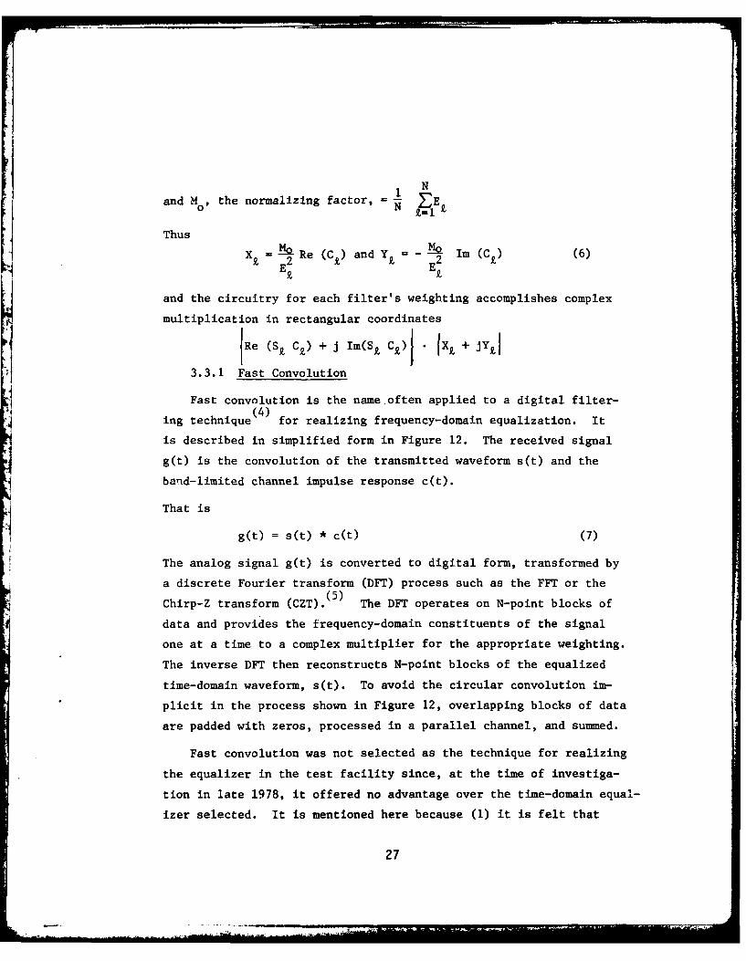
3.3.1 Fast Convolution
Fast convolution is the name often applied to a digital filter-(4)
ing technique for realizing frequency-domain equalization. It
is described in simplified form in Figure 12. The received signal
g(t) is the convolution of the transmitted waveform s(t) and the
band-limited channel impulse response c(t).
That is
g(t) = s(t) * c(t) (7)
The analog signal g(t) is converted to digital form, transformed by
a discrete Fourier transform (DFT) process such as the FFT or the(5)Chirp-Z transform (CZT). The DFT operates on N-point blocks of
data and provides the frequency-domain constituents of the signal
one at a time to a complex multiplier for the appropriate weighting.
The inverse DFT then reconstructs N-point blocks of the equalized
time-domain waveform, s(t). To avoid the circular convolution im-
plicit in the process shown in Figure 12, overlapping blocks of data
are padded with zeros, processed in a parallel channel, and summed.
Fast convolution was not selected as the technique for realizing
the equalizer in the test facility since, at the time of investiga-
tion in late 1978, it offered no advantage over the time-domain equal-
izer selected. It is mentioned here because (1) it is felt that
27

'9
* z
- o
00
ILL,
LU E-4
-J
C-, Y
2 zLU cc
cc cc z1-4
7 W
-H1: jiraw
28

subsequent advances in VSLI technology in general and in CCD tech-
nology in particular have altered the balance somewhat in the dir-
ection of fast convolution and (2) wideband HF modems, in contrast
to this facility, will need to be designed with a view toward min-
imum size, weight, and power. Consequently, use of the latest tech-
nology may be required.
3.4 Transversal Filter Equalizer
In the previous section we described how the probe signal yields
the channel transfer function, C(w), and how this function could be
inverted to provide the weighting coefficients for frequency-domain
equalization. In this section we describe the test facility equal-
izer which operates directly on the received waveform g(t) to restore
it to its original form, s(t). This equalizer can equally well be
described as (1) an inverse filter, (2) a transversal filter, or
(3) a deconvolver. It is a band-limited device operating within the
band W. It computes h(t), the convolution of g(t) and the appro-
priate weighting function v(t). Thus we anticipate that
h(t) = g(t) * v(t) - s(t), (8)
and the device deconvolves s(t) and c(t) within the band W. As can
be seen from the diagram of the equalizer shown in Figure 13,
N
h(t) = g(t-kT) Vk (9)
k= 1
where
Vk = Ak + j Bk
Since N=128 samples of C(w) are provided by the probe signal,
it is convenient to have 128 taps on the tapped delay line.*
*128 is also convenient with respect to the modular design described
in section 4.1.2.
29

K -
0'4
.4
00
;4
30N

We next compute the equalizer's transfer function to determine
the tap weights required for inverse filtering. The band-limited
impulse response of the equalizer is seen by inspection to be
N
V sinlrW(t-kT) . eJwo(t-kT)
W - k -W(t-kT) (10)
where wo is the mid-band frequency (the "carrier").
The Fourier transform of this impulse response, which is the
transfer function of the equalizer and its associated band-limiting
filter, is
Vk e - jW foro -w < < o (W<)k=1
and zero elsewhere.
But this is the expression for the DFT. Thus the equalizer
frequency response is the DFT of the tap weights. Since we aim to1-implement a filter whose transfer function is C(w) , we conclude
that the tap weights are the inverse DFT of the coefficients pre-
viously calculated in 3.3.
In summary then:
0 The probe signal provides the 128 complex samples of C(Qw).
S C(1) is calculated resulting in 128 frequency-domaincoefficients. Typically C - = X+ jY.
0 The 128 complex tap weights are obtained from the 128C9- s via the inverse DFT.
In the event that there is a zero in C(w), the equalizer trans-
fer function's magnitude should go to infinity at the frequency of
the zero amplitude. The phase, however, is interderminate. In
practice, if and when this occurs, an approximation is employed.
In the event of a narrowband interfering signal, which is not
negligible with respect to the probe, a corrupted measurement will
result. The equalizer will, however, tend to provide a null at this
31
frequ ency, probably the best strategy for this case. Later when we
have better understanding of interference (see section 3.6), recom-
mendations for more optimum processing strategies can be made.
3.5 Spread Spectrum Test Signals
Given an equalized wide bandwidth HF channel, the question
arises as to the approach to be taken to make use of this channel.
We have chosen spread spectrum signalling in order to develop a
data base which is relavent to Air Force needs for AJ and/or LPI
communications. The two important classes of spread spectrum wave-
forms are (1) frequency hopping (FH) and (2) direct sequence pseudo-
noise phase modulation (usually called "PN"). Since an FH capability
is implicit in the test facility probe signal transmission and recep-
tion, we have chosen to implement this waveform first. Later it is
planned to add a PN capability (see section 4.7).
3.5.1 FFH Waveform
The FH waveform used in the test facility is called the fast
frequency hop (FFH) waveform. It is derived from the probe signal
by (1) omitting the LFM feature and transmitting at a single frequency
per segment (or "dwell"), and (2) red, cing the duration of the dwell
to less than the usual ionospheric mode path-delay difference so as
to permit mode resolution by way of time gating in the receiver. A
dwell duration of 125 Us is used in the system so as to be compatible
with probe and equalizer parameters. This in effect provides a time
gate of 125 ps. Within this 125 Us time window the equalizer com-
pensates for delay and amplitude variations including those due to
Faraday rotation.
The FFH waveform is phase-coherent over the 128 dwells which
constitute a frame. This frame is 16 ms long and can be used for the
transmission of one or more data bits. One bit per frame will result
in a 42 dB processing gain and a 62.5-b/s data rate.
32

When frequency-hop spread spectrum is used for anti-Jammingpurposes, each dwell frequency is generally selected under the con-trol of a pseudo-random process. For convenience, this system sub-stitutes the probe scrambling format for random frequency selection.Scrambling of this type provides little protection against an ad-versary who wishes to predict where the next dwell will be. This is,however, not an issue in this exploratory program. Demonstratingthe feasibility of scrambled FFH spread spectrum signalling willassure the success of pseudo-random FFH wideband HF communications.
As described in section 3.2, acquisition of the probe signalwill result in a synchronization of the received signal and receiver4 clock to within a timing error commensurate with the unequalizedchannel dispersion. Figure 14 is a sketch of the time-frequencypattern of a single frame of the FFH waveform. The 128 frequenciesarrive at the receiver at different times, depending on the disper-sion of the path. This results in overlapping between dwells. Theequalizer compensates for the dispersion and the overlap is removed.The FH pattern is then demodulated using a locally generated replicaof the transmitted waveform. By refining the receiver clock timingto a small fraction of the dwell interval, a demodulated output is
obtained which is phase-coherent and at a constant frequency through-out the frame,except for small intervals of transition due to the re-sidual receiver clock error.
During these transition intervals, the demodulated frequencyequals the frequency difference between adjacent dwells (from aslittle as 8 kHz to possibly as much as 1016 kHz). By integratingthe demodulated output over the data bit interval, the effects ofthese short-duration frequency excursions are minimized.
33

f 4
f 2
f f lf 1 2 7
0 DWELL f3
I . (ATF) f128
125ps
I FRAME TIME (TF) = 16 msTI
14a: FFH Waveform Transmitted
f4
ff2
f 12 7f3 "-f 2fl
RESIDUAL RECEIVERCLOCK ERROR DEMODULATED
-RECEIVED
- -- EQUALIZED
to + PATH DELAY AT f TIME
14b: FFH Waveform Received, Equalized, and Demodulated
Figure 14: FFH WAVEFORM
34

3.6 Spectrum Analysis of Interference
In section 2.4, the impact of interference on the wideband HF
user was discussed. The approach to the mitigation of interference
is similar to that of dispersion and multipath: i.e. (1) measure the
interference and then (2) compensate for it via the appropriate
signal processing. A capability for interference measurement has
been included in the test facility. These measurements will be used
to develop a quantitative understanding of the nature of the inter-
ference which will later be used to formulate the appropriate signal
processing.
The measurement of interference is achieved at both transmit
and receive sites simultaneously. This will permit later comparative
analysis and assessment of the efficacy of predistorting the trans-
mitted signal in accordance with the measurements made at the trans-
mit terminal. The measurement consists of an analog representation
of the log of the magnitude of the spectrum within the band W.
The technique chosen is called panoramic analysis. It is shown
in Figure 15. A local oscillator repetitively sweeps across the band
W and is mixed with the receiver output. The predetection filter
determines the analyzer resolution. This type of spectrum analysis
was chosen because of its simplicity (as compared with, say, a filter
bank or a Fourier transformer) and the fact that the LO waveform is
easily obtained as an unscrambled version of the probe signal.
3.6.1 Analyzer Resolution
By using the unscrambled probe signal as the LFM LO and by
selecting the panoramic analysis technique, the following parameters
apply:
* W 1024 or 512 kHz
* Ts 1 second
35

).0
0-l
0 x
LU I
*1LU -u
00I-.j
I-HL44
04LIUC uCC '
U g
Tt z360

The time required for the LO to sweep across the resolution
bandwidth AW is
AT =-T = T (12)s W s n
where n is the number of resolution cells. ATs must not, however,
be less than the build-up time of the predetection filter. This
build-up time is at least equal to the reciprocal of AW (and will be
larger for high-order filters).
As a reasonable design value then
1Smin = AW(13)
i iins dwhich for our fastest sweep gives
AWmn=11024 x 103 -- 1 kHz
and
n ,:zI000max
toraoal=rcd hr eodrc n pouewie
Because Ts 1 second, the postdetection bandwdthal sS 000Hz. In our implementation (which is described in section 4.5) the
predetection filter is a low pass filter, and its output is recordedon an audio cassette recorder. The postdetection analyzer output
(after playback of the cassette) is recorded on a chart recorder or
oscillograph. In order to reduce the bandwidth of the information
to that which a reasonably priced chart recorder can reproduce while,
at the same time, not exceeding the bandwidth of a portable cassette
machine, the following parameters were chosen:
W = 6 kHz, or twice the cutoff frequency of a 3 kHz audiocassette recorder,
37

1024 10 n
* 170OHz.
This resolution will resolve the majority of the narrowband
interference carrier lines.
38

SECTION IV
TEST FACILITY DESCRIPTION
In this section the test facility is described in detail.
Figure 16 is a simplified block diagram of the facility which shows
the equipments for transmitting, receiving, equalizing, and record-
ing wideband signals. The upper portion of Figure 16, the transmit
terminal, is housed in the vehicle shown in Figure 17. The interior
of the vehicle is shown in Figure 18. The left-hand photograph is
of the program generator, synthesizer, exciter, and single-sideband
(SSB) transceiver equipment while the right-hand photograph shows
the transmitter amplifiers. A laboratory view of the receive ter-
minal is shown in Figure 19. The left-hand rack contains the equal-
izer, synthesizer, and the program generator; the center rack containsthe Hewlett-Packard (HP) minicomputer and digital displays, and the
right-hand rack contains the receiver front and back ends. (The
wideband tape recorder and the SSB transceiver are not shown in this
view.)
Other equipment (not shown in Figure 16 but which will be des-
cribed in this section) includes the timing circuits (including the
terminal clock), time and frequency synchronization receivers, and
the equipment for spectrum analysis of the interference.
4.1 Equalizer
The circuitry used to implement the transversal f~iter equalizer
(Figure 13) is described in this section. The parameters are as
follows:
N = 128 or 64
= 1/WI JO.9776 ps for W" 1024 kHz1-953 Ps for W - 512 kHz
39

LUL)0
CL 4
LU
zzHr -
U, -w
Uz WL 1-4LU 00 0
00
)- >LU 0E-4
u N0
>zj
LA. UJ
LU LU
Di t Zco -u -
LU
L) < -
ui t4
> LU c
u N40

yNE.
Ib
-41

IFJ
424

~IW
43r
44

iII
T = NT = 62.5 us, 125 Us, or 250 us
The equalizer is realized with all digital circuitry. It operates
at baseband and interfaces with the receiver front end and back end
via the equalizer interface unit. It also interfaces with the co-
j efficient computer and receives its clocking signal from the system
timing generator.
4.1.1 Equalizer Interface Unit
The equalizer interface unit is shown in Figure 20. In addition
to interfacing with the equalizer, it connects with the VR-3700 wide-
band tape recorder facility and provides two sets of LPF's. One set
prevents aliasing in the equalizer input analog-to-digital converters
(ADC) and the other eliminates harmonics from the equalizer output
digital-to-analog converters (DAC). Both sets consist of four filters,
two each for the in-phase (I) and quadrature (Q) channels, one for
W = 1024 kHz, and the other for W = 512 kHz.
The input and output are both at an IF center frequency of
32.012 MHz and a crystal LO at this frequency is used for down-
conversion to baseband and up-conversion back to the IF.
4.1.2 Equalizer Detailed Description
The 128-stage tapped delay line transversal filter described
in section 3.4 has been implemented digitally. The equalizer design
is based on the use of recirculating memories and time-shared, high-
speed digital multiplier/accumulators in a modular arrangement.
In the equalizer (shown in Figure 21) successive samples of
Re [g(t)] and Im [g(t)], in the I and Q input channels respectively,
are weighted and summed to produce Re [h(t)] and Im rh(t)] in the I'
and Q' output channels. Each output sample pair is the sum of 128
complex products
44
..~, ..

U
L. LU IL.
0-o
IL U
uUjw
u-4 W -j
00
4 ! 0
z 14
x2 .i 2c45 L

LU
LA.
0
LU
+ o C
LLU
a 0Z4
C.))
LA.U
'.3a
46D

128
I' + JQt = k + 3Qk (Ak
+ JBk )k=l128 128
(I * - Qk Bk) + j E (Ik* B~ + Q k'Ak) (14)k=1 k=1
The four terms j I.A, E Q.B, E I-B, and E Q-A are computed first
and then combined to give the two desired output sample values.
The I and Q channel input samples are quantized to 8 bits in
amplitude. The sampling rate is either 1024 or 512 kHz depending on
the choice of W. The Ak and B coefficients are also 8-bit words
which are entered into the equalizer at a rate determined by the co- -efficient computer but synchronized with the equalizer sampling clock.
Figure 22 shows the shaded area of Figure 21 in detail. It
includes the I-channel digital tapped delay line and the A-channel
coefficient storage register (which are actually identical in their
implementation). Eight multiplier/accumulators each compute the sum
of 16 products by a time-sharing arrangement involving the local
recirculation of 16 stages of memory content. The 16-bit products
from the multipliers are rounded to 12 bits. The accumulators send
16 bits to the 8-to-i MUX. The final accumulator combines the 8 MUX
outputs and sends 19-bit data to the combiner. Before entering the
DAC's (see Figure 21),a front panel controlled scaler circuit selects
the best 10 bits of the 20-bit combiner output.
A pipeline structure is used in the implementation of the equal-
izer to achieve the high throughput speed. A 1-bit or 2-bit pipeline
delay permits processing the preceding result while simultaneously
acquiring the next input sample. In the digital multiplier, the 8-
bit multiplier and 8-bit multiplicand are loaded into their "x" and
47

LU
zZ
0 uj
00
00
0 4-
1-4
NzH
ca 0
cc 0
u 48

"y" registers while the product of the previous operands is simultan-
eously loaded into its output register. Because of the delay in the
output register, latches or storage registers are required between
the multiplier and accumulator to achieve the high throughput speed.
4.1.3 High-Speed Digital Multiplier Problem
The time-sharing multiplication scheme described above requires
that each 8-bit by 8-bit multiplication be completed within 57.4
nanoseconds which is one seventeenth of the ADC sampling interval.
TRW model MPY-8HJ-1 devices are employed which were specified to have
a typical 250 C multiply time of 45 ns and a maximum multiply time
over 00 C to 600C of 60 ns. We expected that the maximum multiply
time at room temperature would be less than the required 57.4 ns, but
we discovered that under certain data-dependent conditions this was
not the case. A cooperative effort with TRW uncovered the cause and
led to the resolution of the difficulty. TRW subsequently supplied
us with a new set of upgraded devices which meet our requirements.
We have also developed a circuit clocking modification which permits
slower operation (by a few nanoseconds) and provides additional pro-
tection against multiplier speed variations with age, temperature
and power supply changes.
4.1.4 Equalizer Testing
The equalizer has been extensively tested to demonstrate its
capabilities. One example of this testing is to use one tapped delay
line (say the I channel) and one storage register (say the A storage
register) to compute a correlation function (128 1 k Ak). Special
built-in t. st equipment is used to load a maxtmum-length sequence
binary phase code for m - 63 into the first 63 stapes of the storage
register (the last 65 stages are set to zero). The same m = 63 code
Is then repetitively clocked into the tapped delay line at 1024 kHz.
Figure 23 shows the results of this test. Figure 23a displays slightly
49

23a: m = 63 Maximum Length Sequence
23b: Autocorrelation Function for m = 63 Sequence as Seen at
I' Output W = 1024 kHz
Figure 23: EQUALIZER TEST RESULTS50

more than one cycle of the repeating sequence, and Figure 23b shows
the circular correlation function seen at the equalizer's I' channel
output when the B register and/or Q channel are set to zero. Relative
to the zero voltage level, the mainlobe is +63 and all sidelobes are
-1 as expected.
4.2 Coefficient Computer
The coefficient computer receives frequency-domain measurements
of the transmitter-to-receiver path, computes the appropriate fre-
quency-domain equalizer coefficients, and transforms these coefficients
into the time domain as complex tap weights for use by the system's
transversal filter equalizer. A block diagram showing the coefficient
computer and its various interfaces is shown in Figure 24.
The ADC's sample the received one-second probe frame at a
higher rate than the required 128 Hz. This oversampling avoids the
excessive circuit delays which would be associated with anti-aliasing
filters at a 128 Hz sampling rate. The redundant samples are combined
to yield the required 128 complex samples of the channel transfer
function. These are then unscrambled using information from the
synthesizer programming circuits before the coefficients are computed.
The complex tap weights for the equalizer are available approximately
200 ms after the end of the one second probe (T p) is received. Out-
puts for both 128- and 64-point equalization are provided.
4.2.1 Coefficient Computer Software
As shown in Figure 25, the coefficient computer software per-
forms the following functions:
W The ADC samples are combined and unscrambled thus pro-viding a sampled data, rectangular coordinate represen-tation (CRZ) of the channel transfer function {C(w)}.
* The frequency domain weights (Z, M Xk + JY are computedaccording to equation (6).
51

0
X a. L o
<I r- z
06~ CL uj L LAJ
0 u cr u0 404
-
IL N 9
u - 2. 0
o cr u.j -- 4
C.) 4) I~.9
m D -J0 w uc8ci-
II. cc -U J C
0I 2U CA
3E IL (fL U.
(3 0 Zul cc
toU."2 0
52

U) -
R L- 00.L. Nwi.
z -J z
0.
0
0 2
C..
UL
Lu
CL~
LU,
ca'
LU% w c w-
2 2W
Lu CC
0 L
53z

0 The equalizer coefficients (V Ak + JBk) are computed.They are the inverse FFT of the Z£ set.
0 The coefficients are loaded into the equalizer A and Bstorage registers.
0 The FFT section can also be used to provide the trans-form of Cx which is the channel impulse response.
0 For display and/or plotting, rectangular coordinates aremapped to polar coordinates, thus providing the magnitudeand phase of Ci, Zn, Vk, or the transform of Ck. The logof the magnitude is also provided.
4.2.2 Coefficient Computer Hardware
All software functions are presently implemented on an HP 2115A
minicomputer. This equipment is in the process of being upgraded to
the newer HP 21MX. An HP 1300A large-screen CRT display, an HP 7005B
X/Y plotter, and a Hazeltine 1420 CRT terminal constitute the asso-
ciated peripherals.
4.3 Time/Frequency Circuits
In this section the programmed frequency synthesizers and the
equipment and circuits used to supply all the necessary timing sig-
nals and local oscillator frequencies is described. The block dia-
gram of the time/frequency circuits is shown in Figure 26. (The
frequency standard, clock generation, and timing generator circuitry
is not shown in the test facility system block diagram of Figure 16.)
4.3.1 Frequency Standards
The frequency and timing generators at each terminal of the
test facility are all referenced to a standard one-megahertz signal.
This standard is the one-megahertz quartz crystal oscillator within
the Rockland synthesizer. The HP synthesizer is used to provide a
band-set local oscillator function. Its driver also is used for local
54

u z
wucn
00
LU L,
u cI-j
LLJ LL Aicc cc0
04 q>
LL U cc 0uj oJcc-
ccJz < o 0
0J M .- w> L Z1-uINI
Z ca 55

oscillator frequency synthesis. Interterminal frequency synchroniza-
tion will eventually be achieved by referencing each terminal's
standard to a common external reference signal as provided by standard
frequency broadcasts from WWVB. In the present stand-alone configur-
ation, the standard oscillator's long-term stability of one part in
109 per day results in a need to occasionally readjust one of the
standards.
4.3.2 Clock Generation
The clock rates employed in the system are derived using phase-
locked-loop (PLL) techniques. The basic system clock rate is equal
to the higher value of W of 1024 kHz while the system "fast clock",
used in the equalizer, is seventeen times this value, i.e., 17.408 MHz.
A functional block diagram of the circuitry involved is shown in Fig-
ure 27. Epoch synchronization between the two terminals is achieved
using the procedure described in section 4.6 and implemented by inter-
rupting the master clock for a selected number of clock pulses.
4.3.3 System Timing Generator
The digital logic used to generate the required timing wave-
forms is shown in Figure 28. The 1024 kHz master clock is divided
down in two chains; the following outputs are provided:
* probe and LFM or FFH mode start-of-frame (T p/T )
* probe and LFM start-of-segment (AT ) or FFH start-of-dwell (ATf) (2ATf is also used to increment the Af counterin the probe and LFM modes.),
* load command to the Rockland synthesizer,
* reset commands to the AF counter, and
0 one Hertz "ticks" for time marks on recordings and for
WWV/CHU synchronization.
56

0N*1 ~ -J
A
4U
zj
u0 LU
:1LU _
LUL
-i z,he CC u L
A .- a.O C-
w0
C.14
w
80 to
C.),
cn 0
57

zuviUaw
mw iLC0- .CN u C% LooW ~ 0 i.-
- 0
0 rm
CL
E--
Cw14
cwZ
~~Iio58-

One of two timing regimes can be selected by a front-panel switch.
A slow timing regime based on a one second frame time (T p) provides1P
ATp = _- second and At = 125 Us. In the fast timing regime, thep128
frame time (Tf) is 16 ms and ATf = 125 Us.
4.3.4 Program Generation
The Rockland synthesizer employs a 32-bit digital word to sel-
ect the desired output frequency. The method of control used permits
the 13 least significant bits to be set to zero while the remaining
19 bits are programmed. Because of the particular format used byRockland for synthesizer control, deriving the control programs is
done by pre-programming electrically programmable read only memories
(EPROM's) with the EPROM contents being read out and fed to the
Rockland control inputs under the command of conventional binary
logic.
A functional block diagram showing the program generation logic
appears in Figure 29. The AF EPROM contains eight programs, each
containing 128 8-bit words, for coarse frequency (AF) selection.
The AF values are either 4, 8 or 16 kHz apart, depending on the sel-
ected values of bandwidth (W) and number (N) of segments/dwells. The
AF EPROM address counter is clocked by AT in the probe and LFM modesP
and by ATf in the FFH mode.
The Af EPROM contains three programs, each containing 64 11-bit
words, for fine frequency positioning. The Af values are 64 Hz, 128
Hz, or 256 Hz apart. All three programs cause the synthesizer to
generate a staircase approximation to LFM within a probe or LFM
mode segment. The Af address counter changes Af every 125 us (At).
The phase error relative to true LFM is given by
1AO = ± At Af in revolutions (15)
For At - 125 Us and Af - 256 Hz, AO - ± 1.44 degrees. In the FFHAF
mode, Af is held fixed at a value corresponding to approximately A-
59

IcDzz
U. I
m
-J _ Luj 0 < (:
uj vCo 0CC r3
LiccLi
06

An eight-position front-panel rotary switch for program selec-
tion together with the slow-fast timing regime switch is used to
select the desired mode (probe, LFM, or FFH), bandwidth (W), and num-
ber of segment/dwells (N). Each rotary switch position corresponds
to a program in the AF EPROM. Table I lists the synthesizer output
waveform parameters for the various control settings.
The FFH waveforms available in program G provide a means for
moderate band signalling which can be used under favorable ionospheric
conditions without the need for channel equalization. Program H is
essentially the same as program A except the frequency dwells on the
edges of the band have been translated to the central 768 kHz so as
to provide a means of FFH signalling which does not exceed the down-
converter LPF cutoff frequency of ± 400 kHz.
4.3.5 Frequency Synthesizers
The system employs two Rockland model 5100 programmable fre-
quency synthesizers - one in the transmit terminal for probe, FFH,
and LFM waveform generation, and one in the receive terminal for
probe and FFH frequency demodulation as well as for LFM waveform
generation. The synthesizers feature direct digital synthesis, and
were selected because of their full programmability and fast switch-
ing capability over a greater-than-2-MHz band.
4.4 Transmitter and Receiver Analog Circuits
In this section the antennas, transmit terminal exciter and
power amplifier chain, and the receive terminal front end and back
end are described. Since the exciter and the receiver front end are
duals of one another and use identical circuit modules, they are
discussed first.
61

4.300
0N
ww V~*
m Uo 0
~004-.>
u 4)U 0 a H.
Ka-a,'-
00 co 0 cc ~ o-7
CYC
>4.
I I
* ~ ~ 0 cc-- -. 0
CL U. 0. CL IIE"
CI M. 1- Wa-E r . r .c(UCf
Ix,-
LIoI LI U0
- (- ~ U- - I .'. I C62

4.4.1 Exciter and Receiver Front End
Because of the wideband signals used in the test facility, no
conventional equipments or IF and other circuit modules that met the
requirements of the exciter and the receiver front end were available.
In the exciter it is necessary to take the up to 1024 kHz bandwidth
waveform centered at 1512 kHz from the Rockland synthesizer and to
frequency-translate this signal to any section of the HF band between
4 and 30 MHz. This is done first by up-converting to a 32 MHz IF
center frequency and then by double-converting via a 46 MHz IF to the
desired HF band center frequency.*
In the receiver, the opposite is required. The signal from
anywhere in the 4- to 30-MHz HF band is double-converted via a 46-MHz
IF strip to an IF at 32 MHz. Here the signal is distributed to (1)
the equalizer and the wideband tape recorder facility via the equal-
izer interface unit, (2) the receiver back end for down-conversion
and demodulation of the probe signal, and (3) the spectrum analysis
circuitry (see section 4.5). The block diagrams of the exciter and
the receiver front end are shown in Figure 30. Because of the more
severe dynamic range requirements in the receiver, out-of-band noise
and interference are removed at the antenna output with a tunable
preselector band pass filter.
In both terminals an HP 5110A frequency synthesizer and its
associated driver are used for local oscillator generation (see alse
Figure 26). The up-converter is also used in the receive terminal
spectrum analysis circuits. All interunit connections are via a
patch panel which is used in the transmit terminal to reconfigure
the exciter circuit modules into a receiver for spectrum analysis.
*Here and elsewhere in this report the exact center frequencies of32.012 MHz and 45.988 MHz are approximated for readability.
63

0 m UL
z
2 c c
N
0 cc 0
om oJC4 0 cz
C4 LL. O
ONN
z z V >
L 64
The receiver front end has a measured dynamic range of 60 dB
(from 1 dB compression to the noise level). Worst-case spurious
signals are 42 dB down when the maximum input signal is applied. The
exciter output spectrum for W = 1024 kHz and an RF frequency of 6 MHz
is shown in Figure 31. The third harmonic is 45 dB down. For higher
RF frequencies 'he harmonic level decreases. For lower frequencies
it increases to 30 dB down at 4 MHz.
4.4.2 Transmitter Amplifier Chain
The transmitter chain can deliver at least 500 watts of RF
output power anywhere in the 4- to3G-MHz frequency range. It consists
of three separate units: a 4-watt broadband low-power driver, a
100-watt intermediate power broadband driver, and a 500-watt high-
power broadband amplifier.
4 All amplifiers operate in a linear (class A or B) mode and use
wideband circuitry. Therefore, no adjustments are required when
changing from one frequency to another. For RF center frequencies
below 10 MHz,the third harmonic is within the 4- to 30-MHz band. Two
high-level low pass filters are therefore used in this frequency
region to reduce the harmonic content. The block diagram of the
transmitter chain is shown in Figure 32.
The measured output spectrum at 500 watts and a RF center fre-
quency of 6.6 MHz is shown in Figure 33.
4.4.3 Antennas
The following antennas are available for use with the test
facility:
A. Receive Terminal Antennas
0 Dual 16-element phased array. Boresites 450, 2550.Steerable over ±450.
65

00
LU
4a4
F ,U4
CI
H,
114
66U

z0z0
UJ
wLJ
E-4
.En
u w
wh4 4 0)
mw x
10 U. z4
67

L6-z
LrAQ
LL.Z.2
(NOISIAIG/EIP'- wL (n iO I
al
08H

* oblique log-periodic antenna (LPA). Boresite 2000.6.5 to 30 MHz. Vertical polarization.
" Oblique LPA. Boresite 2000. 6.5 to 30 MHz. Horizon-
tal polarization (used with SSB transceiver).
* Whip. (Used with WWV/CHU receiver).
0 Zenith-directed LPA. 4 to 13 MHz. (Used for reception
of Boston-Hill transmissions).
B. Transmit Terminal Antennas
* Transportable, oblique LPA. 12-to 22-MHz or 16-to
30-MHz Horizontal polarization.
0 Bowtie. Located at Boston Hill. 1-MHz bandwidth at5.5 MHz.
0 Bowtie. Located at Boston Hill. 1-MHz bandwidth at6.6 MHz.
0 Bowtie. Located at Boston Hill. I-MHz bandwidth at7.7 MHz.
* Whip for SSB Transceiver
* Whip for WWV/CHU Receiver
The bowtie antennas were designed and built under this project.
They are essentially broadband dipoles, horizontally polarized so as
to give a modest zenith directivity.
4.4.4 Receiver Back End and Display
This unit is shown in Figure 34. It accepts a 32-MHz IF wide-
band signal from either the receiver front end or the qualizer inter-
face unit. In-phase and quadrature IF signals are generated at 1.512
MHz by down-conversion with a 30.5-MHz LO. The probe or FFH frequency
modulation is then removed in a second down-converter to baseband
which uses the Rockland synthesizer as its local oscillator. At
baseband, 100 kHz LPF's eliminate the IF and LO signals. The output
69

000
P4
A0 z
NIONZ
Ln cc0 .
CLL
000
N LLZ
U. >
700

I and Q signals are sent (1) directly to the coefficient computer's
ADC's and (2) via 400 Hz LPF's to a CRT display which is used for
signal acquisition (as described in sections 3.2.1 and 3.5.1).
4.5 Spectrum Analysis Equipment
To spectrum analyze the interference in either a 1024-kHz or
512-kHz band, the Rockland synthesizer is programmed to output an LFM
waveform which sweeps over the desired band in one second. The
Rockland output is up-converted to 32 MHz where it is used to syn-
chronously detect a 32-MHz IF amplifier output. A 3-kHz LPF sets the
predetection bandwidth to 6 kHz. At each site the LPF output is
recorded on an audio cassette tape recorder along with 1 Hertz timing
marks. Later both cassettes are played back at MITRE/Bedford, and
the signals are detected, log-amplified, and recorded on an oscillo-
graphic chart recorder.
The spectrum analysis circuitry in the receive terminal is shown
in Figure 35. In the transmit terminal, the exciter is reconfigured
as a receiver whose output is filtered in a 32-MHz IF amplifier and
fed to the spectrum analysis equipment. Figure 36 shows this arrange-
ment with those circuits not used in the exciter enclosed by a dashed
line. (This equipment is not shown in the test facility system
block diagram of Figure 16).
4.6 Peripheral Equipment
Equipments for voice communications, display, and recording not
previously described are discussed in this section.
4.6.1 WWV/CHU Reception and Synchronization
A McKay-Dymec DR55 Comirunication Receiver is included in each
terminal. This equipment receives broadcasts from WWV or CHU, usually
via a whip antenna, and outputs a one-Hertz time "tick". This signal
71

ci-' 0
x uH
0 LU
U.' -L9.-wU <o
in0>2sm <O<CrCL Lj MM 4
I.-
LU 0&LZ4
00ruj 0
0 < LLZ uJ
UA 002 LU LL.
000-r 0U
L L N
ILLU
72x

LUL
Iz 0LiJ
I U u f 0 OL
C4,
(n 0 CL, N C
cc LU0NL I I- :)
cz In--
*1c u cLL Z
w W -4
I LL~u
4 00
x o P
P-4
0 w0
cc CLLL. 0
732

is compared to the local one-Hertz time tick from the timing gener-
ator on an oscilloscope, and the local clock is interrupted for the
appropriate time duration so as to achieve coarse epoch synchroniza-
tion at each terminal. The receiver terminal clock is next inter-
rupted for the estimated propagation delay between the terminals, and
then the receiver back-end display is used for signal acquisition as
described in sections 3.2.1 and 3.5.1. This equipment is shown in
Figure 37. (It is not shown in the test facility system block diagram
of Figure 16.)
4.6.2 SSB Voice Communications
Collins KWM-2A 3.5- to 30-MHz transceivers with 100-watt output
capability are used for voice communications between the transmit
and receive terminals. Appropriate HF channels have been allocated,
and either a whip of a LPA antenna is used at each end of the circuit.
4.6.3 Wideband Recording Facility
The Bell and Howell VR-3700 Tape Recorder is a 14-channel ma-
chine. It is operated at 60 inches per second where it provides a
0.4-to 750-kHz channel bandwidth.* Three recording tracks are made
on each tape. Each track uses four channels: (1) I channel, (2) Q
channel, (3) time reference, and (4) frequency reference for playback
speed control. The phase error between the I and Q channels has
been measured as 200 RMS for the worst track.
The I and Q channels are used to record the input to the equal-
izer. Playback is either through the equalizer or around it to the
Interface Unit's up-converter. This equipment is shown in Figure 38.
*The information below 0.4 kHz is lost but this only comprises 0.004or 0.002 of the total signal spectrum for W - 512 kHz and 1024 kHzrespectively.
74

LU 0
IE-
40
0
0
zz00
4nrT0 03
cc
LLz z4zCL LU
75.

-J00
I-LU 0
OZ 4
0 0 r44
4 cc
02w w -C - U c9
w >~ -J < LU
00 0
U. -A H
LU LU 4 CL.Z z C. be 4 4
0 - _ _0_ _ __U_ _<
LUU
FF U.-LU.
LU
-JLU
76
4.7 PN Spread Spectrum Capability
A discrete sequence PN phase modulation and demodulation cap-
ability is not presently available but will be added to the test
facility since it appears to have advantages for low-probability-of-
intercept communications which complement the advantage the FFH
waveform has with respect to anti-jamnming.
The PN waveform will be a simple bi-phase modulated signal at a
chipping rate of 1024 or 512 kb/s. A fairly long repeating linear
sequence with good autocorrelation properties can be used to permit
mode isolation in the receiver signal processing. This can be accom-
plished by limiting the time duration of the receiver correlator win-
dow to less than the typical mode spacing. For convenience the sys-
tem will use a 125 Us correlation window.
To process the PN signal in the receiver, one alternative is to
use the equalizer to also serve as a matched-filter correlator by
loading the appropriate N chips (usually 128) from the receiver PN
sequence generator into the most significant bits of the A & B
registers every T sec (usually 125 us). One-bit multiplication
(exclusive - OR) of the PN code and the coefficient computer output
is required. Another alternative is to implement separate circuitry
devoted to the correlation task. Charge transfer device correlators
are available which are suitable for this application.
77

SECTION V
EXPERIMENTAL PROGRAM
Preliminary (shake-down) system tests have already been com-
pleted (May 1980) between Boston Hill and MITRE/Bedford. In these
tests, the transmit terminal and the equipment in the receive ter-
minal required for probe signal reception and acquisition were suc-
cessfully checked out.
The complete test facility as described in section IV will be
first used in a proof-of-concept demonstration on a Florida-to-MITRE/
Bedford ionospheric path. This demonstration will also be the be-
ginning of an extensive experimental measurement program to establish
a data base for future wideband HF modem designs. The transmit ter-
minal will be moved to several points in North America and signals
received from the transmit terminal at MITRE/Bedford will be recorded
and analyzed.
The available choices of spread spectrum modulation will be used
and the equalizer will be configured in various ways using the built-
in flexibility with respect to W, T, and its dynamic range. The
interference spectrum will also be recorded at both sites.
The planned upgrading of the test facility to include a PN spread
spectrum capability (see section 4.7) will proceed in parallel with
the measurement program. When this upgrading is completed, additional
testing from a site (or sites) already used will be undertaken.
5.1 Data Taking
The following ionospheric paths will be investigated:
a short range (20 km): from MITRE's facility at Boston Hillin North Andover, MA.
79
pMjQXPAGI BL"K.NO FIU4D

0 long range, one-hop (1.5 to 2 megameters) from the south-eastern CONUS,
0 long range, multihop (3 to 4 megameters) from the westernCONUS, and
0 near the auroral oval, from Newfoundland.
Results from subsequent analysis (see section 5.2) will be used
to refine the type of data taken as the program progresses. It may
be desirable to repeat some of the early measurements to incorporate
these refinements on a comparative basis and to investigate the
ionospheric variation over a transseasonal interval.
Wideband recordings of the receiver output (unequalized) will
permit later playback via the equalizer during which the equalizer
parameters can be varied.
5.2 Data Analysis
The data base to be established can be described as a matrix
of data sets having the following four dimensions:
1) Distance and/or location: Path lengths from 20 km to over3000 km oriented south-north and west-east in the temperatezone and also a path near the auroral oval.
2) Time: Diurnal (daytime, dusk, nightime) and seasonal.
3) Spread spectrum waveforms: FFH and PN, 1024 and 512 kHzbandwidths.
4) Equalizer parameters: 64 and 128 taps, up to 8 bits ofamplitude, 1024 and 512 kHz bandwidth.
These data will be analyzed to determine quantitative relationships
between the various dimensions. For example, assuming 24-hour oper-
ation, recommended equalizer parameters can be derived for a particu-
lar application as described by dimensions (1) and (3).
so

The interference power spectrum data will be analyzed to deter-
mine the correlation of the measurements at the transmitter site with
those at the receiver site and to derive recommendations leading
towards equipment or techniques to mitigate the effects of this
interference.
81

LIST OF REFERENCES
1. D. J. Belknap, R. D. Haggarty, B. D. Perry "Adaptive Signal Pro-cessing for Ionospheric Distortion Correction" MTR-746, MITRECorporation, August 1968, or ESD TR 70-30, March 1970.
2. B. D. Perry "Real-Time Correction of Wideband Oblique HF Paths",MTR-1905, MITRE Corporation, August 1970, or ESD TR 70-371,November 1970.
3. B. D. Perry, D. R. Bungard, J. H. Reisert, G. B. Tiffany, S. S.Weinrich "Project 7140: Wideband HF Technology. Report forFY1979" MTR-3846, MITRE Corporation, September 1979.
4. M. R. Epstein "A Statistical Description of an IonosphericChannel" TR 142, Stanford Electronics Laboratory, July 1967.
5. R. H. Reck "Faraday Rotation Effects at HF" MITRE WP-403127 September 1971.
6. D. J. Belknap, R. D. Haggarty, B. D. Perry "Six Month Report on
Activities Conducted for Project 7160 by Members of the AdvancedTechniques Subdepartment" MITRE WP-1444, May 1967.
7. "Nonrecursive Digital Filtering Using Cascade Fast Fourier Trans-formers", G. C. O'Leary, IEEE Trans. Audio and Electroacoustics,Volume AU-18, June 1970.
8. M. A. Jack et al "Real Time Network Analysers Based on SAW ChirpTransform Processors" 1976 IEEE Ultrasonics Symposium Proceedings.
83
. . _ .. ... .... .. 51,,5wIJ ' 1L1J